

Page 1
SERVICE MANUAL
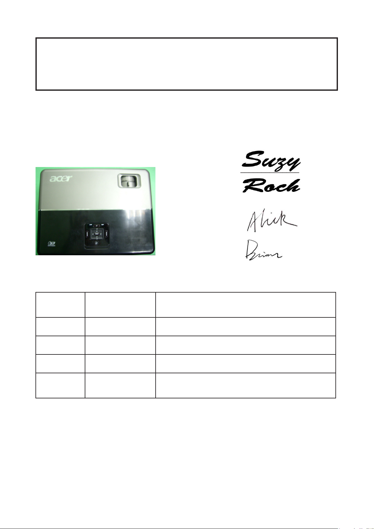
Model Name : P5270/P5270 Refresh
Prepared by SI :
________________________________________
Prepared by TSE :
________________________________________
Check by :
________________________________________
Approved by :
________________________________________
Date Revise Version Description
2007/07/17 V1.0 Initial Issue
2007/08/08 V2.0 Modify Chapter 5
2008/08/15 V3.0 Add P5270 Refresh,Modify CH1
2008/10/10 V4.0
Copyright Oct, 2008. All Rights Reserved P/N: 36.87W10G001
Add Waveform Download in Chapter5, modify
Chapter4, Chapter6 and AppendixB
Page 2

RSPL Comparison
Parts P5270 P5270 Refresh
MAIN BOARD 70.87W12GR01 70.87W44GR01
KEYPAD BOARD 80.87H03G001 80.87U03G003
Condential
I
P5270/P5270 Refresh
Page 3

Preface
This manual is applied to P5270/P5270 Refresh projection system. The
manual gives you a brief description of basic technical information to help in
service and maintain the product.
Your customers will appreciate the quick response time when you immediately identify problems that occur with our products. We expect your customers
will appreciate the service that you offer them.
This manual is for technicians and people who have an electronic
background. Please send the product back to the distributor for repairing
and do not attempt to do anything that is complex or is not mentioned in the
troubleshooting.
Notice:
The information found in this manual is subject to change without prior
notice. Any subsequent changes made to the data herein will be incorporated
in future edition.
P5270/P5270 Refresh Service Manual
Copyright Oct.2008
All Rights Reserved
Manual Version 4.0
Condential
II
P5270/P5270 Refresh
Page 4

Table of Content
Chapter 1 Introduction 1-1
Product Highlight 1-1
Compatible Mode 1-4
System Block Diagram 1-8
Bottom Cover Demension 1-9
Chapter 2 Disassembly Procedure 2-1
Equipment Needed & Product Overview 2-1
Disassemble Lamp Cover Module and Top Cover Module 2-3
Disassemble Keypad Module 2-5
Disassemble Top Support Shielding 2-6
Disassemble Back Cover 2-7
Disassemble Front Cover Module 2-8
Disassemble Left Cover Module & Right Cover Module 2-10
Disassemble Speaker 2-11
Disassemble Lamp Module 2-12
Disassemble Main Board Module 2-13
Disassemble Fan Module 2-14
Disassemble LVPS Bracket , Mylar & LVPS Module 2-15
Disassemble Engine Module 2-17
Disassemble ROD Module 2-19
Disassemble Color Wheel Module 2-21
Disassemble DMD Board & DMD Chip Module 2-22
Disassemble Mask 2-23
Disassemble Interrupt Switch Module 2-24
Disassemble Lamp Driver Module 2-25
Disassemble Blower Module 2-26
Disassemble Bottom Support Shielding 2-27
Disassemble Elevator Module 2-28
Chapter 3 Troubleshooting 3-1
LED Lighting Message 3-1
Beep Sound 3-2
Main Procedure 3-3
Condential
III
P5270/P5270 Refresh
Page 5

Chapter 4 Function Test & Alignment Procedure 4-1
Test Equipment Needed 4-1
Service Mode 4-1
Reset (OSD) 4-2
Test Condition 4-2
Inspection Procedure 4-4
Chapter 5 Firmware Upgrade 5-1
Equipment Needed 5-1
Firmware Upgrade Mode 5-1
Installation Procedure 5-2
Firmware Upgrade Procedure 5-6
Waveform Download 5-8
Chapter 6 EDID Key-in Procedure 6-1
Equipment Needed 6-1
Setup Procedure (VGA1,VGA2,DVI) 6-4
EDID Key-In Procedure 6-5
Setup Procedure (HDMI) 6-9
Default Language Reset 6-12
Appendix A
P5270/P5270 Refresh Exploaded Overview 7-1
Appendix B
SerialNumberSystemDenition 7-15
PCBACodeDenition 7-17
Appendix C
RS232 Command Code 7-18
Condential
IV
P5270/P5270 Refresh
Page 6
Chapter 1
Introduction
1-1 Highlight
No Item Description
1
2 Weight - 3.0kg
3
4 Cabinet
5
Dimensions - 299 x 105 x 229.3mm (W x H x D)
- Advanced Air Flow
- Two fans with system acoustic noise level
Cooling
System
Lamp
Housing
- Temperature control circuits with adaptive fan rotational
speeds
- High altitude cooling mode
- Maximum touch temperature follow UL60950-1
- Provides space for PCB boards, fans, optical engine,
power supply and lamp
- Lamp Assembly could be changed by customer himself,
but should read the user manual for instruction in ad vance.
- Lamp Assembly should be provided by Coretronic and
distributed through authorized agencies.
6 Tilt Angle - 7 degree with elevator mechanism
7 Materials - Plastic cosmetic
8
Condential
System
Controller
- TI DDP2230
1-1
P5270/P5270 Refresh
Page 7

1-2
P5270/P5270 Refresh
Condential
No Item Description
- 310W(Max.) normal mode (without wireless module)
- 240W+-10% ECO mode (without wireless module)
(for P5270);
9
10 Terminals
Power Consumption
- 220W(Max.) ECO mode (without wireless module)
(for P5270 Refresh)
- Standby < 10W (without wireless module)
(for P5270)
- Standby < 5W (without wireless module)
(for P5270 Refresh)
- HDMI Female Terminal X 1
- DVI-I Female Terminal X 1
- VGA input ( D-SUB X 2)
- VGA output ( D-SUB X 1)
- Video input (RCA jack Type X 1, Mini DIN 4-pin S-video X1)
- Audio input (Phone jack Type X 2)
- USB (Type-B X 1)
- RS232 (Mini DIN 3-pin X 1)
11 Video signal
12
13
14
Keystone
Correction
Projection
Lens
Throw
Distance
- Standards :
NTSC (3.58/4.43)
PAL (B/D/G/H/I/M/N)
SECAM (B/D/G/K/K1/L)
HDTV - 480p, 576p, 720p, 1080i
- +/ -40 degree (80 degree)
- F# 2.41 ~2.55, f = 21.79~23.99 mm, 1.10X Mechanical
Zoom Lens
- 1.0m – 12m (Optical Performance)
Better display at 60”
Page 8
1-3
P5270/P5270 Refresh
Condential
No Item Description
Engineer spec and Marketing spec:
- 2550 ANSI Lumens (Typical; Full power mode)
(for P5270)
- 2150 ANSI Lumens (Minimum; Full power mode)
15 Brightness
16 Contrast
17 Uniformity
(for P5270)
- 2700 ANSI Lumens (Typical; Full power mode)
(for P5270 Refresh)
- 2400 ANSI Lumens (Minimum; Full power mode)
(for P5270 Refresh)
Engineer spec and Marketing spec:
- 1100 : 1 Full White and Black (Minimum; Full power mode)
- 1800 : 1 Full White and Black (Typical; Full power mode)
Engineer spec and Marketing spec:
- 75% Japan standard (Minimum; Full power mode)
- 85% Japan standard (Typical; Full power mode)
18 Lamp - 220 Watt Philips E20.6 Lamp
19 Safety - UL, cUL, TüV—GS,CB report, CCC
20
21
22
23 Lamp Life
24 Altitude
Temperature
Maximum
Humidity
Acoustic
Noise Level
- Operating: 5°C -- 35°C
- Storage: -20°C -- 60°C
- Operating: 5°C -- 35°C, 80%RH (Max.), non-condensing
- Storage: -20°C -- 60°C, 80%RH (Max.), non-condensing
- typical 34 dB(A) and maximum 36 dB(A) at 23+/-2 deg C
for the full power mode (220W)
- typical 31 dB(A) and maximum 33 dB(A) at 23+/-2 deg C
for the eco mode (172W)
Follow ISO 7779 regulation, A-weighted sound pressure
level measurement, color wheel speed 7200 rpm
- 3000 hours min, 50% survival rate (Full power Mode)
- 4000 hours min, 50% survival rate (Echo power Mode)
- Operatin - for 0 -- 2500 ft, 5 -- 35 deg C
for 2500 -- 5000 ft, 5 -- 30 deg C
for 5000 -- 10000 ft, 5 -- 25 deg C
- Storage -20 -- 60 deg C
maximum 40000 ft
Page 9

1-4
P5270/P5270 Refresh
Condential
No Item Description
25 MTBF - Operating more than 25,000 hrs (90% condence level)
26
Color
Wheel
- 6 segments (R90Y28G90C28W42B82)
- 7200 rpm
Page 10
1-5
P5270/P5270 Refresh
Condential
1-2 Compatible Mode
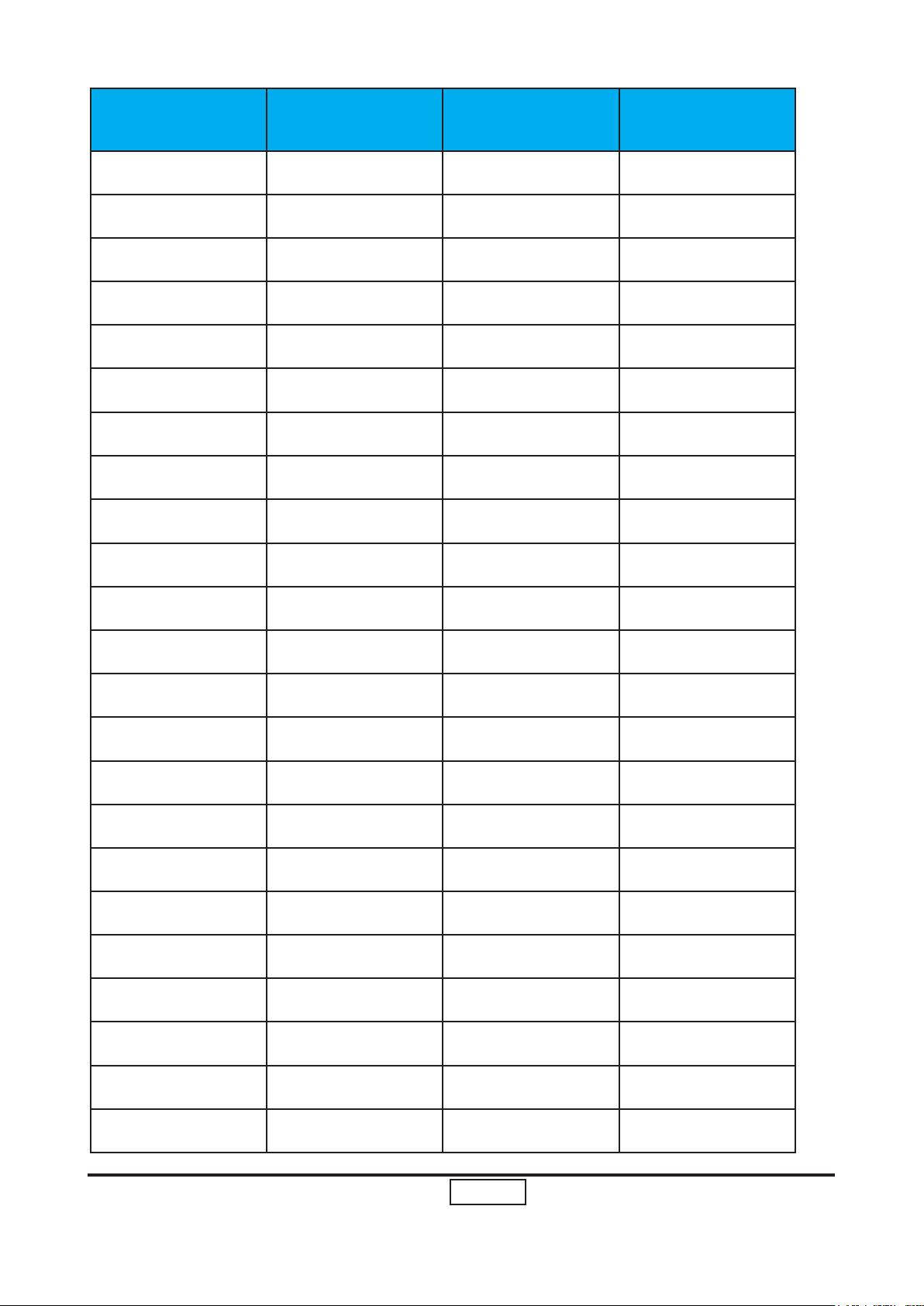
A. VGA Analog
Mode Resolution V-Sync (Hz) Horiz.Freq.(KHz)
VGA 640x480 60 31.50
VGA 640x480 72 37.90
VGA 640x480 75 37.50
VGA 640x480 85 43.30
VGA 720x400 70 31.50
VGA 720x400 85 37.90
SVGA 800x600 56 35.20
SVGA 800x600 60 37.90
SVGA 800x600 72 48.10
SVGA 800x600 75 46.90
SVGA 800x600 85 53.70
SVGA 832x624 75 49.725
XGA 1024x768 60 48.40
XGA 1024x768 70 56.50
XGA 1024x768 75 60.00
XGA 1024x768 85 68.70
SXGA 1152x864 70 63.80
SXGA 1152x864 75 67.50
SXGA 1152x864 85 77.10
SXGA 1280x1024 60 63.98
SXGA 1280x1024 72 76.97
Page 11
1-6
P5270/P5270 Refresh
Condential
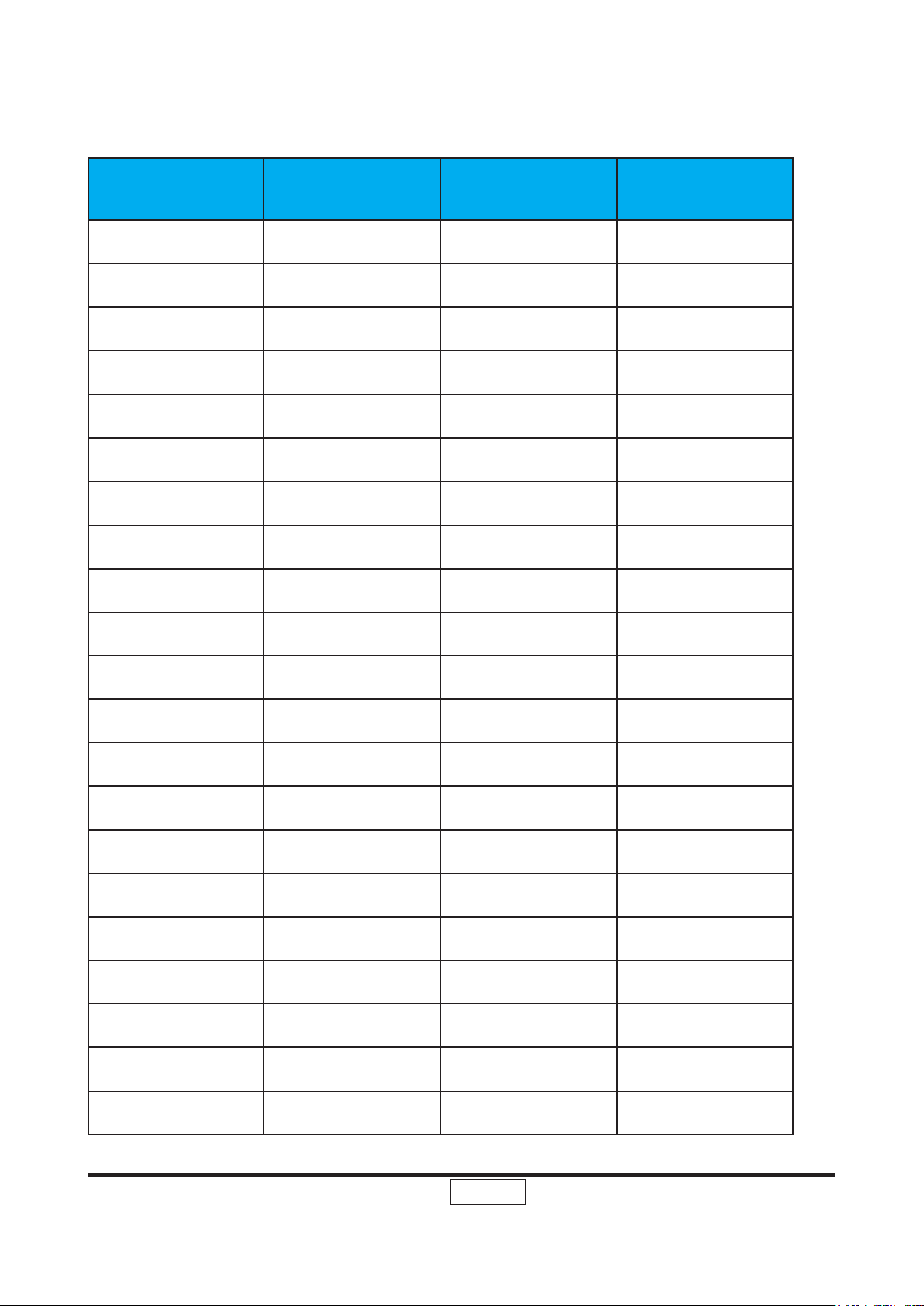
Mode Resolution V-Sync (Hz) Horiz.Freq.(KHz)
SXGA 1280x1024 75 79.98
SXGA 1280x1024 85 91.10
QuadVGA 1280x960 60 59.70
QuadVGA 1280x960 75 75.23
SXGA+ 1400x1050 60 63.98
UXGA 1600x1200 60 75.00
Power Mac G4 640x480 66.6(67) 34.93
Power Mac G4 800x600 60 37.90
Power Mac G4 1024x768 60 48.40
Power Mac G4 1152x870 75 68.68
Power Mac G4 1280x960 75 75.00
Power Mac G4 1280x1024 60 63.98
Power Mac G4 640x480 60 31.35
Power Mac G4 640x480 66.6(67) 34.93
Power Mac G4 800x600 60 37.90
Power Mac G4 1024x768 60 48.40
Power Mac G4 1152x870 75 68.68
Power Mac G4 1280x960 75 75.00
Power Mac G4 1280x1024 60 63.98
i Mac DV(G3) 1024x768 75 60.00
WXGA 1280x768 60 48.36
WXGA 1280x768 75 57.60
WXGA 1280x768 85 68.63
Page 12

1-7
P5270/P5270 Refresh
Condential
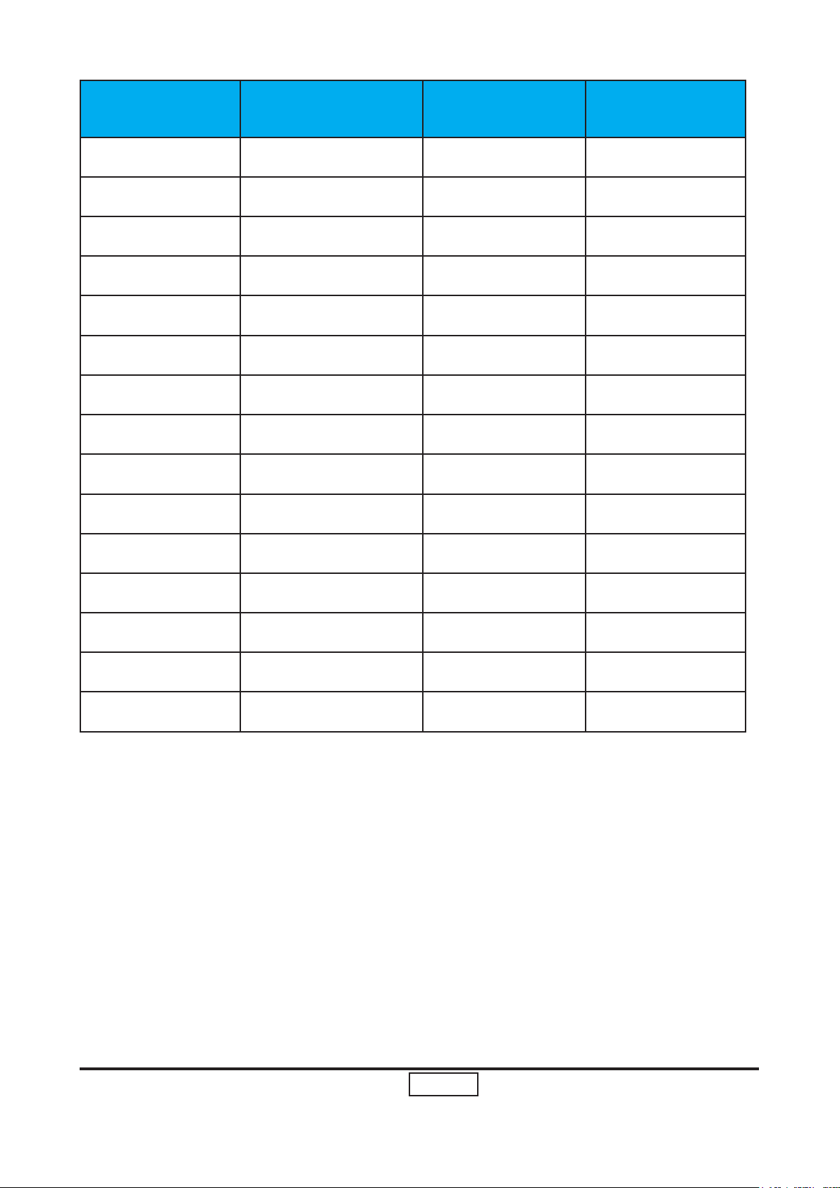
Mode Resolution V-Sync (Hz) Horiz.Freq.(KHz)
WXGA 1280x720 60 45.00
WXGA 1280X800 60 49.702
WXGA 1360x768 60 47.72
WXGA 1440x900 60 55.935
Page 13
1-8
P5270/P5270 Refresh
Condential
B. DVI Digital
Mode Resolution V-Sync (Hz) Horiz.Freq.(KHz)
VGA 640x480 60 31.50
VGA 640x480 72 37.90
VGA 640x480 75 37.50
VGA 640x480 85 43.30
VGA 720x400 70 31.50
VGA 720x400 85 37.90
SVGA 800x600 56 35.20
SVGA 800x600 60 37.90
SVGA 800x600 72 48.10
SVGA 800x600 75 46.90
SVGA 800x600 85 53.70
SVGA 832x624 75 49.725
XGA 1024x768 60 48.40
XGA 1024x768 70 56.50
XGA 1024x768 75 60.00
XGA 1024x768 85 68.70
SXGA 1152x864 70 63.80
SXGA 1152x864 75 67.50
SXGA 1152x864 85 77.10
SXGA 1280x1024 60 63.98
SXGA 1280x1024 72 76.97
Page 14

1-9
P5270/P5270 Refresh
Condential
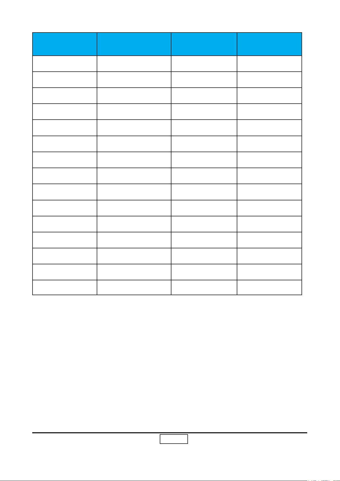
Mode Resolution V-Sync (Hz) Horiz.Freq.(KHz)
SXGA 1280x1024 75 79.98
SXGA 1280x1024 85 91.10
QuadVGA 1280x960 60 59.70
QuadVGA 1280x960 75 75.23
SXGA+ 1400x1050 60 63.98
UXGA 1600x1200 60 75.00
Power Mac G4 640x480 66.6(67) 34.93
Power Mac G4 800x600 60 37.90
Power Mac G4 1024x768 60 48.40
Power Mac G4 1152x870 75 68.68
Power Mac G4 1280x960 75 75.00
Power Mac G4 1280x1024 60 63.98
Power Mac G4 640x480 60 31.35
Power Mac G4 640x480 66.6(67) 34.93
Power Mac G4 800x600 60 37.90
Power Mac G4 1024x768 60 48.40
Power Mac G4 1152x870 75 68.68
Power Mac G4 1280x960 75 75.00
Power Mac G4 1280x1024 60 63.98
i Mac DV(G3) 1024x768 75 60.00
WXGA 1280x768 60 48.36
WXGA 1280x768 75 57.60
WXGA 1280x768 85 68.630
Page 15
1-10
P5270/P5270 Refresh
Condential
Mode Resolution V-Sync (Hz) Horiz.Freq.(KHz)
WXGA 1280x720 60 45.00
WXGA 1280x800 60 49.702
WXGA 1360x768 60 47.72
WXGA 1440x900 60 55.935
WXGA 1680x1050 60 65.290
480i (NTSC) 720x480(1440x480) 59.94(29.97) 27.00
480p (NTSC) 720x480 59.94 31.47
576i (PAL) 720x576(1440x576) 50(25) 27.00
576p (PAL) 720x576 50 31.25
720p (NTSC) 1280x720 60 45.00
720p (PAL) 1280x720 50 37.50
1080i (NTSC) 1920x1080 60(30) 33.75
1080i (PAL) 1920x1080 50(25) 33.75
1080p (NTSC) 1920x1080 60 33.75
1080p (PAL) 1920x1080 50 33.75
Page 16

1-11
P5270/P5270 Refresh
Condential
C. HDMI Digital
Mode Resolution V-Sync (Hz) Horiz.Freq.(KHz)
VGA 640x480 60 31.50
VGA 640x480 72 37.90
VGA 640x480 75 37.50
VGA 640x480 85 43.30
VGA 720x400 70 31.50
VGA 720x400 85 37.90
SVGA 800x600 56 35.20
SVGA 800x600 60 37.90
SVGA 800x600 72 48.10
SVGA 800x600 75 46.90
SVGA 800x600 85 53.70
SVGA 832x624 75 49.925
XGA 1024x768 60 48.40
XGA 1024x768 70 56.50
XGA 1024x768 75 60.00
XGA 1024x768 85 68.70
SXGA 1152x864 70 63.80
SXGA 1152x864 75 67.50
SXGA 1152x864 85 77.10
SXGA 1280x1024 60 63.98
SXGA 1280x1024 72 76.97
Page 17

1-12
P5270/P5270 Refresh
Condential
Mode Resolution V-Sync (Hz) Horiz.Freq.(KHz)
SXGA 1280x1024 75 79.98
SXGA 1280x1024 85 91.10
QuadVGA 1280x960 60 59.70
QuadVGA 1280x960 75 75.23
SXGA+ 1400x1050 60 63.98
UXGA 1600x1200 60 75.00
Power Mac G4 640x480 66.6(67) 34.93
Power Mac G4 800x600 60 37.90
Power Mac G4 1024x768 60 48.40
Power Mac G4 1152x870 75 68.68
Power Mac G4 1280x960 75 75.00
Power Mac G4 1280x1024 60 63.98
PowerBook G4 640x480 60 31.35
PowerBook G4 640x480 66.6(67) 34.93
PowerBook G4 800x600 60 37.90
PowerBook G4 1024x768 60 48.40
PowerBook G4 1152x870 75 68.68
PowerBook G4 1280x960 75 75.00
Power Mac G4 1280x1024 60 63.98
i Mac DV(G3) 1024x768 75 60.00
WXGA 1280x768 60 48.36
WXGA 1280x768 75 57.60
WXGA 1280x768 85 68.630
Page 18
1-13
P5270/P5270 Refresh
Condential
Mode Resolution V-Sync (Hz) Horiz.Freq.(KHz)
WXGA 1280x720 60 45.00
WXGA 1280x800 60 49.702
WXGA 1360x768 60 47.72
WXGA 1440x900 60 55.935
WXGA 1680x1050 60 65.290
480i (NTSC) 720x480(1440x480) 59.94(29.97) 27.00
480p (NTSC) 720x480 59.94 31.47
576i (PAL) 720x576(1440x576) 50(25) 27.00
576p (PAL) 720x576 50 31.25
720p (NTSC) 1280x720 60 45.00
720p (PAL) 1280x720 50 37.50
1080i (NTSC) 1920x1080 60(30) 33.75
1080i (PAL)W 1920x1080 50(25) 33.75
1080p (NTSC) 1920x1080 60 33.75
1080p (PAL) 1920x1080 50 33.75
Page 19
1-14
P5270/P5270 Refresh
Condential
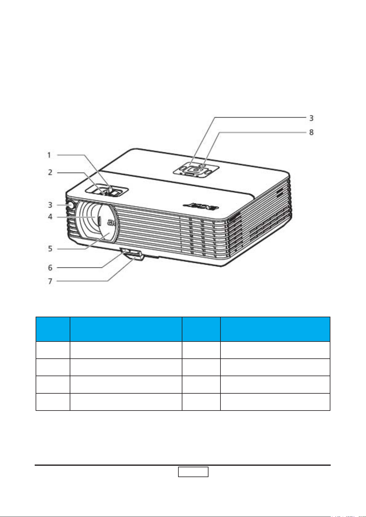
1-3 Product Overview
Front / upper side
Item Description Item Description
1 Zoom ring 5 Lens cap
2 Focus ring 6 Elevator button
3 Remote control receiver 7 Elevator foot
4 Zoom lens 8 Control panel
Page 20
1-15
P5270/P5270 Refresh
Condential
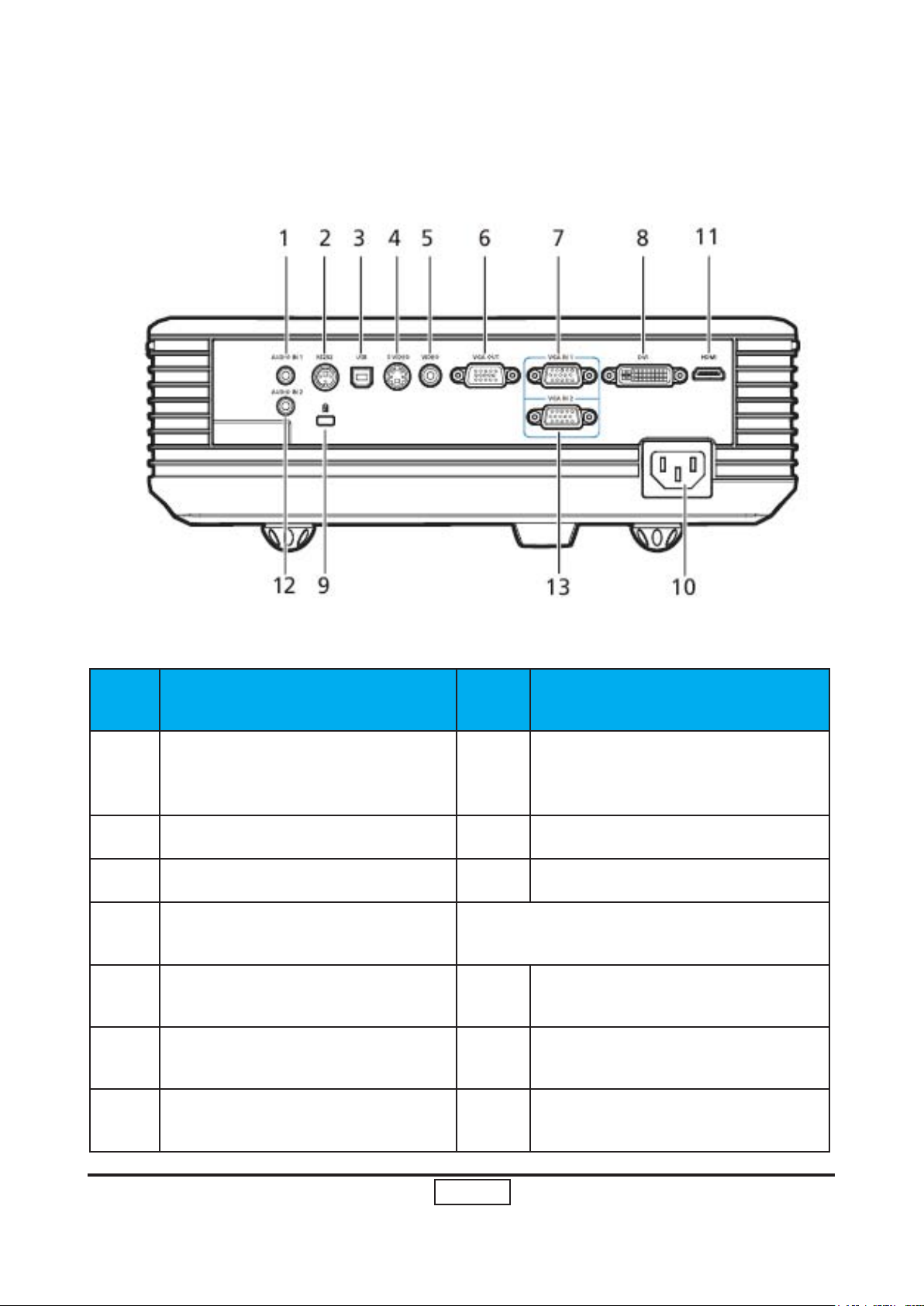
Rear side
Item Description Item Description
DVI input connector (for digital
1 Audio input connector (1) 8
2 RS232 connector 9 KensingtonTM lock port
3 USB connector 10 Power socket
4 S-Video input connector
5
6
7
Composite video input connector
Monitor loop-through output
connector (VGA-Out)
PC analog signal/HDTV/component video input connector (1)
Below items are for P5260/P5271 series
only
11 HDMI connector
12 Audio input connector (2)
13
signal
with HDCP function)
PC analog signal/HDTV/component video input connector (2)
Page 21
1-16
P5270/P5270 Refresh
Condential
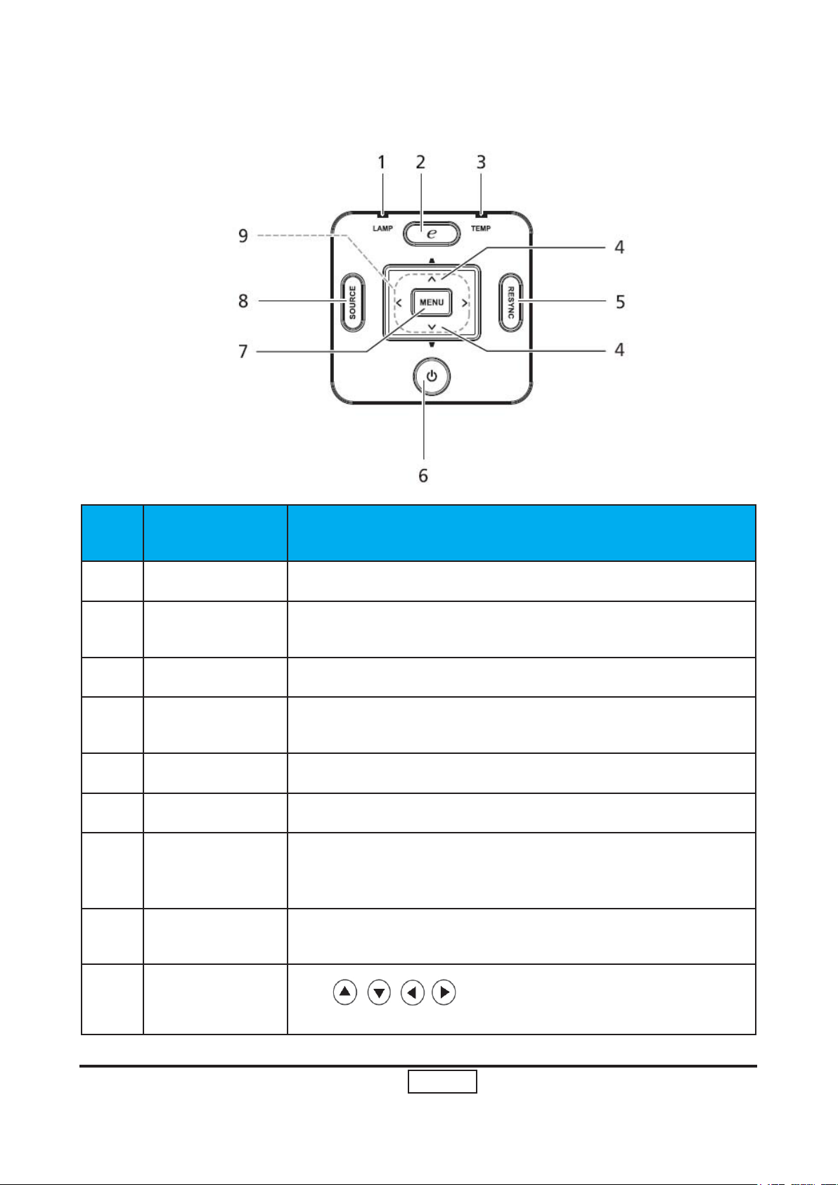
Control Panel
Item Function Description
1 LAMP Lamp Indicator LED
2
3 TEMP Temp Indicator LED
4 Keystone
5
6
7
8
Empowering
key
RESYNC Automatically synchronizes the projector to the input source.
POWER See the contents in “Turning the Projector On/Off” section.
MENU
SOURCE
Unique Acer functions: eOpening, eView, eTimer.
Adjusts the image to compensate for distortion caused by
tilting the projector (±16 degrees).
• Press “MENU” to launch the Onscreen display (OSD) menu or
exit the OSD menu.
• Conrm your selection of items.
Press “SOURCE” to choose RGB,Component, S-Video, Composite, DVI, HDTV and HDMI™ sources.
9
Four directional
select keys
Use
your selection.
to select items or make adjustments to
Page 22
1-17
P5270/P5270 Refresh
Condential
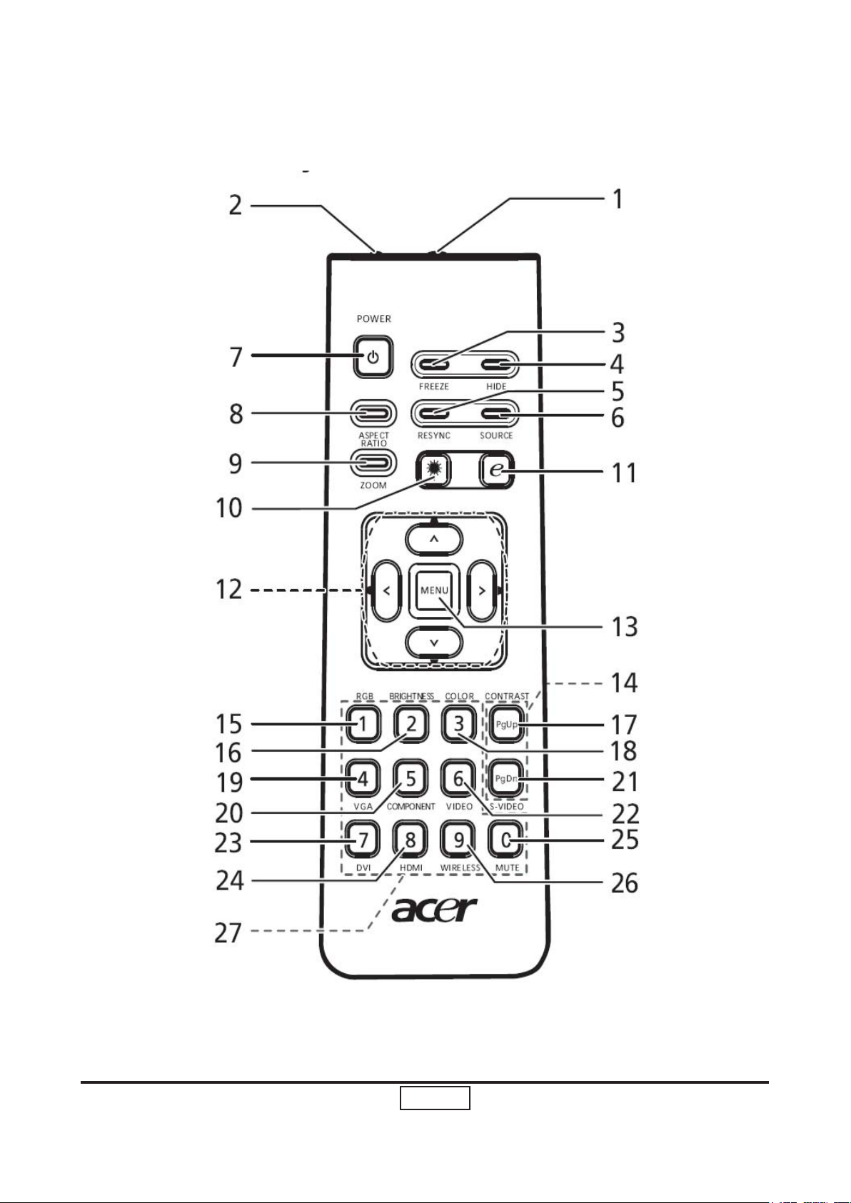
Remote Control Layout
Page 23
1-18
P5270/P5270 Refresh
Condential
Item Icon Function Description
1
2 Laser pointer Aim the remote at the viewing screen..
3 FREEZE To pause the screen image.
4 HIDE
5 RESYNC
6 SOURCE
7 POWER
8
Infrared
transmitter
ASPECT
RATIO
Sends signals to the projector.
Momentarily turns off the video. Press "HIDE" to
hide the
Automatically synchronizes the projector to the
input source.
Press “SOURCE” to choose from RGB, Component-p, Component-i, S-Video, Composite,
DVI-D, Video and HDTV sources.
Refer to the “Turning the Projector On/Off” section.
To choose the desired aspect ratio
(Auto/4:3/16:9).
9 ZOOM Zooms the projector display in or out.
Aim the remote at the viewing screen, press and
10 Laser button
11
12 KEYSTONE
13 MENU
14 PAGE
15 RGB Press “RGB” for true-color optimization.
Empowering
key
hold this button to activate the laser pointer.This
function is not supported in Japanese market.
Unique Acer functions: eOpening, eView, eTimer
Management.
Adjusts the image to compensate for distortion
caused by tilting the projector (± 16 degrees).
To launch the onscreen display (OSD). To exit
the OSD, press“MENU” again and conrm your
selection.
For computer mode only. Use this button to
select the next or previous page. This function is
only availablewhen connected to a computer via
a USB cable.
Page 24
1-19
P5270/P5270 Refresh
Condential
16
17
BRIGHTNESS
CONTRAST
Press “BRIGHTNESS” to adjust the brightness of the
image.
Use the “CONTRAST” option to control the difference between the lightest and darkest parts of the
picture.
18
19
20
21
22
23
24
COLOR
VGA
COMPONENT
S-VIDEO To change source to S-Video.
VIDEO To change source to COMPOSITE VIDEO.
DVI
HDMI™
Press “COLOR” to adjust the color temperature of
image.
Press “VGA” to change source to the VGA connec-
tor. This connector supports analog RGB, YPbPr
(480p/576p/720p/1080i), YCbCr (480i/576i) and
RGBsync
Press “COMPONENT” to change source to Com-
ponent video.This connection supports YPbPr
(480p/576p/720p/1080i) and YCbCr (480i/576i).
Press “DVI” to change source to DVI. This connection supports digital RGB, analog RGB, YPbPr
(480p/576p/720p/1080i),YCbCr (480i/576i) and
HDCP signals.
To change source to HDMI™. (for the model if with
HDMI™ connector)
25
26
27
MUTE To turn on/off the volume.
Press “WIRELESS” to display the image which is
WIRELESS
KeyPad 0~9
wirelessly transmitted from the PC to the projector via
the “Acer eProjection Management” utility. (for wireless model)
Press “0~9” to input a password in the “Security set-
tings”.
Page 25
1-20
P5270/P5270 Refresh
Condential
Note:
Page 26
1-21
P5270/P5270 Refresh
Condential
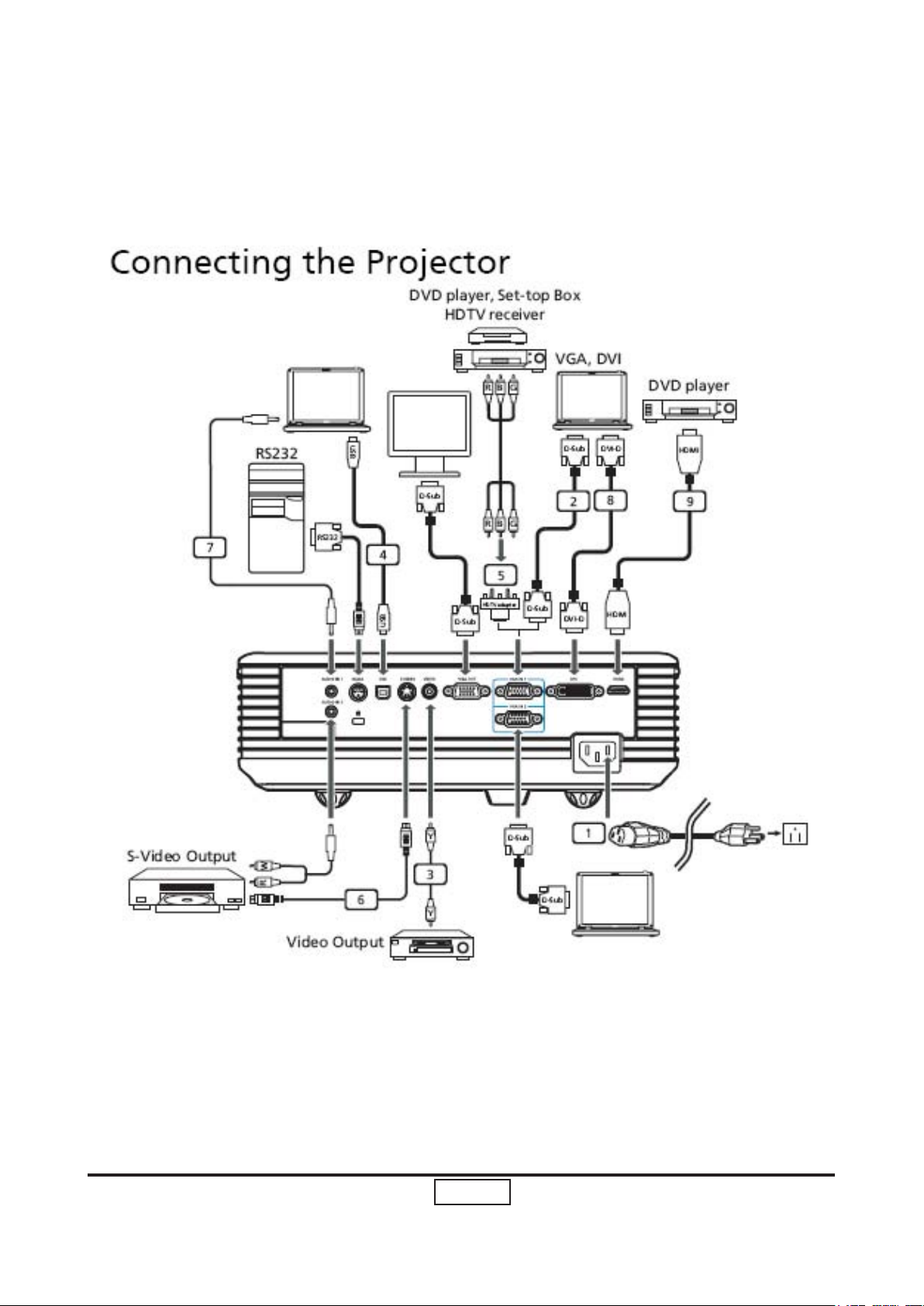
Getting Started
Page 27
1-22
P5270/P5270 Refresh
Condential
Item Description Item Description
1 Power cord 6 S-Video cable
2 VGA cable 7 Audio cable jack/jack
3 Composite video cable 8 Audio cable jack/jack
4 USB cable 9
5
Note: To ensure the projector works well with your computer, please make sure the
timing of the display mode is compatible with the projector.
VGA to component/HDTV
adapter
HDMI cable (P5260/5271
series)
Page 28
1-23
P5270/P5270 Refresh
Condential
System Block Diagram
Bottom Cover Dimension
Page 29
Condential
1-24
P5270/P5270 Refresh
Page 30
Chapter 2
Disassembly Process
2-1 Equipment Needed & Product Overview
Item Photo Item Photo
Screw Bit (+)
:107
Hex Sleeves
8mm
Long Nose
Nipper(Left)
Hex Sleeves
5mm
Tweezers
Screw Bit
Angle
Cutting
Nipper(Right)
Condential P5270/P5270 Refresh
(+) :102
2-1
Page 31

2-2
P5270/P5270 RefreshCondential
Item Photo Item Photo
Front Side Back side
Left Side Right Side
Top Cover
Bottom
Cover
Page 32

2-3
Condential P5270/P5270 Refresh
2-2 Disassemble Lamp Cover Module and Top Cover
Module
No Procedure Photo
1 (1) Press 2 latches to pull up
Lamp Cover Module
(as yellow ellipse)
(2) Unscrew 6 screws on top
cover
(as red circle)
(3) Unscrew 2 screws on back
cover
(as yellow circle)
(4) Unplug 1 connector
(as yellow square)
Page 33

2-4
P5270/P5270 RefreshCondential
No Procedure Photo
2 (1) Disassemble Top Cover
Module& Lamp Cover
Module
(2) Disassemble Lamp Cover
Module from Top Cover
Module
NOTE: When you Disassemble the Lamp
Cover Module, you have to push forward it from
the Top Cover Module.
(As the picture show)
Lamp Cover Module
Top Cover Module
Page 34

2-5
Condential P5270/P5270 Refresh
2-3 Disassemble Keypad Module
No Procedure Photo
1 (1) Unscrew 4 screws
(as red circle)
(2) Unplug 1 Connector
(as yellow square)
(3) Disassemble all compo nents of Keypad Module
Top Cover
Page 35

2-6
P5270/P5270 RefreshCondential
2-4 Disassemble Top Support Shielding
No Procedure Photo
1 (1) Unscrew 6 screws
(as red circle)
(2) Disassemble Top Support
Shielding
Top Support Shielding
Page 36

2-7
Condential P5270/P5270 Refresh
2-5 Disassemble Back Cover
No Procedure Photo
1 (1) Unscrew 8 hex screws
(as green circle)
(2) Unscrew 2 screws
(as red circle)
(3) Disassemble Back Cover
Back Cover
Page 37

2-8
P5270/P5270 RefreshCondential
2-6 Disassemble Front Cover Module
No Procedure Photo
1 (1) Unscrew 2 screws
(as red circle)
(2) Unplug 1 connector
(as yellow square)
(3) Disassemble Front Cover
Module
Front Cover Module
Page 38

2-9
Condential P5270/P5270 Refresh
No Procedure Photo
2 Press 1 tenon to disassemble
IR Sensor
(as yellow square)
IR Sensor
Page 39

2-10
P5270/P5270 RefreshCondential
2-7 Disassemble Left Cover Module & Right Cover
Module
No Procedure Photo
1 (1) Unscrew 1 screw on left
side to disassemble Left
Cover Module
(as red circle)
(2) unscrew 1 screw and un plug 1 connector on right
side to disassemble Right
Cover Module
(as yellow circle and yellow
square)
(3) Take out 1 spring on
each side to disassemble 2
latches
(as red square)
Latches & Springs
Page 40

2-11
Condential P5270/P5270 Refresh
2-8 Disassemble Speaker
No Procedure Photo
1 (1) Unscrew 2 screws on
Right Cover Module
(as red circle)
(2) Disassemble Speaker
Speaker
Page 41

2-12
P5270/P5270 RefreshCondential
2-9 Disassemble Lamp Module
No Procedure Photo
1 (1) Unscrew 2 screws
(as red circle)
(2) Disassemble Lamp Module
Lamp Module
Page 42

2-13
Condential P5270/P5270 Refresh
2-10 Disassemble Main Board Module
No Procedure Photo
1 (1) Unscrew 4 screws
(as red circle)
(2) Unplug 6 connectors
(as yellow square)
(3) Disassemble Main Board
& Mylar
Main Board
Page 43

2-14
P5270/P5270 RefreshCondential
2-11 Disassemble Fan Module
No Procedure Photo
1 (1) Unscrew 3 screws to dis-
assemble Fan Module
(as red circle)
(2) Unscrew 4 screws to dis asemble Fan & Bracket
(as green circle)
NOTE: The thermal switch
cable must go along the
dent. (As the Blue circle)
Page 44

2-15
Condential P5270/P5270 Refresh
2-12 Disassemble LVPS Bracket , Mylar & LVPS Module
No Procedure Photo
1 (1) Disassemble a Sponge
(as yellow square)
(2) Unscrew 1 ground screw
(as green circle)
(3) Unscrew 4 screws to dis assemble LVPS Bracket &
Mylar
(as red circle)
(4) Unplug 3 Connectors
(as yellow square)
Page 45

2-16
P5270/P5270 RefreshCondential
No Procedure Photo
2 Disassemble LVPS Module
LVPS Module
Page 46

2-17
Condential P5270/P5270 Refresh
2-13 Disassemble Engine Module
No Procedure Photo
1 (1) Unscrew 4 screws
(as red circle)
(2) Disassemble Engine Mod ule
Engine Module
Page 47

2-18
P5270/P5270 RefreshCondential
No Procedure Photo
2 (1) Unscrew 1 screw
(as red circle)
(2) Disassemble thermal
switch
(3) Unscrew 1 screw
(as green circle)
(4) Disassemble Zoom Ring
and Focus Ring
Thermal Switch
Zoom Ring
Focus Ring
Page 48

2-19
Condential P5270/P5270 Refresh
2-14 Disassemble ROD Module
No Procedure Photo
1 (1) Unscrew 2 screws
(as red circle)
(2) Disassemble Mylar
(3) Unscrew 1 screw
(as green circle)
(4) Disassemble ROD Hide
Ray Plate
Mylar
ROD Hide Ray Plate
Page 49

2-20
P5270/P5270 RefreshCondential
No Procedure Photo
2 (1) Unscrew 2 screws
(as red circle)
(2) Disassemble ROD Fix
Plate and ROD Module
Page 50

2-21
Condential P5270/P5270 Refresh
2-15 Disassemble Color Wheel Module
No Procedure Photo
1 (1) Unscrew 2 screws
(as red circle)
(2) Disassemble Color wheel
Module
(3) Unscrew 1 screw
(as green circle)
(4) Disassemble Color Wheel
and Photo Sensor
Color Wheel
Photo Sensor
Page 51

2-22
P5270/P5270 RefreshCondential
2-16 Disassemble DMD Board & DMD Chip Module
No Procedure Photo
1 (1) Unscrew 2 hex screws
(as green circle)
(2) Disassemble DMD Board
& DMD Chip Module
2 (1) Rotate the switch
(as yellow circle)
(2) Disassemble DMD Chip
from DMD Board
DMD Board & DMD Chip Module
Page 52

2-23
Condential P5270/P5270 Refresh
2-17 Disassemble Mask
No Procedure Photo
1 (1) Press 1 tennon to loosen
the lamp driver cable
(as yellow square)
(2) Unscrew 1 screw
(as red circle)
(3) Disassemble Mask
Mask
Page 53

2-24
P5270/P5270 RefreshCondential
2-18 Disassemble Interrupt Switch Module
No Procedure Photo
1 (1) Unscrew 1 screw
(as red circle)
(2) Disassemble Interrupt
Switch Module
(3) Disassemble Interrupt
Switch from Interrupt
Switch Support
Interrupt Switch
Page 54

2-25
Condential P5270/P5270 Refresh
2-19 Disassemble Lamp Driver Module
No Procedure Photo
1 (1) Unscrew 1 screw to disas-
emble Lamp Driver
Module
(as red circle)
(2) Press 4 tenons
(as yellow circle)
(3) Disassemble Lamp Driver
from Lamp Driver Support
Lamp Driver Module
Page 55

2-26
P5270/P5270 RefreshCondential
2-20 Disassemble Blower Module
No Procedure Photo
1 (1) Unscrew 3 screws to dis
assemble Blower Module
(as red circle)
(2) Disassemble all compo nents of Blower Module
Blower
Rubber
Page 56

2-27
Condential P5270/P5270 Refresh
2-21 Disassemble Bottom Support Shielding
No Procedure Photo
1 (1) Unscrew 2 screws
(as red circle)
(2) Disassemble Bottom Sup port Shielding
Bottom Support Shielding
Page 57

2-28
P5270/P5270 RefreshCondential
2-22 Disassemble Elevator Module
No Procedure Photo
1 Disassemble the Rubber
(as red square)
Rubber
Page 58

2-29
Condential P5270/P5270 Refresh
No Procedure Photo
2 (1) Unscrew 2 screws
(as red circle)
(2) Disassemble 1 Spring
(as yellow square)
(3) Press 1 tenon to
disassemble all compo nents of Elevator Module
(as red square)
Page 59

No Procedure Photo
3 The disassembly is complet-
ed.
Bottom Cover
2-30
P5270/P5270 RefreshCondential
Page 60

Chapter 3
Troubleshooting
3-1 LED Lighting Message
Lamp LED Temp LED Power LED
Message
Red Red Red Blue
Standby
(power cord plugged in)
Lamp retry OFF OFF OFF Quick Flash
Turning off
(cooling state)
Turning off
(cooling completed)
Error (thermal failure) OFF OFF OFF ON
Error (fan lock failure) OFF Quick Flash OFF ON
OFF OFF ON OFF
OFF OFF Quick Flash OFF
OFF OFF ON OFF
Error (lamp breakdown) ON OFF OFF ON
Error (color Wheel fail) Quick Flash OFF OFF ON
Condential P5270/P5270 Refresh
3-1
Page 61

3-2
P5270/P5270 Refresh
Condential
3-2 Beep Sound
Power on (as soon as power button
pressed)
Power on (lamp lighting failed) 2 x {So(0.1s) – Off(0.1s)} per lighting failure
Power on (lens cap was not opened, for
the model with sliding lens cover only)
Close lens cap while projector is operating (for the model with sliding lens
cover only)
Power off (power button pressed twice) So(0.3s)
Fan lock So(0.1s) periodically per second
Overheat 2 x {So(0.1s) – Off(0.1s)} periodically per sec-
Lamp error 3 x {So(0.1s) – Off(0.1s)} periodically per sec-
Lamp Life reminding 3 x {Do(0.2s) – Off(0.8s) – So(0.2s) – Off(0.8s)}
Presentation Timer (time is up) 3 x {Do(0.1s) – Off(0.9s)} - So(0.5s)
So(0.3s)
12s interval for each trial lighting. Max 4 times
of trial
2 x {So(0.1s) – Off(0.1s)} periodically per 3 seconds, Totally 5 cycles. Turn off projector after 5
cycles.
2 x {So(0.1s) – Off(0.1s)} periodically per 3 seconds, Totally 5 cycles. Turn off projector after 5
cycles.
ond
ond
with reminding message
Page 62

3-3
Condential P5270/P5270 Refresh
3-3 Main Procedure
No Symptom Procedure
1 No Power - Ensure the Power Cord and AC Power Outlet are securely
connected
- Check Lamp Cover and Interrupt Switch
- Ensure all connectors are securely connected and aren’t
broken
- Check Lamp Driver
- Check LVPS
- Check Main Board
2 Auto Shut
Down
3 No Image - Ensure the Signal Cable and Source work
- Check LED Status
a. Lamp LED Light
- Check Lamp
- Check Lamp Driver
- Check Main Board
b. Temp LED Light
- Check Thermal Sensor
- Check Thermal Switch
- Check Fan
c. Color Wheel
- Check Color Wheel
- Check Photo Sensor
(If you connect multiple sources at the same time, use the
“Source” button on the control panel to swtich)
- Ensure all connectors are securely connected and aren’t
broken
- Check Main Board
- Check DMD Board
- Check Color Wheel
- Check DMD Chip
- Check Engine Module
Page 63

3-4
P5270/P5270 Refresh
Condential
No Symptom Procedure
4 No Light On - Ensure all connectors are securely connected and
aren’t broken
- Check Lamp Module
- Check Lamp Driver
- Check LVPS
- Check Main Board
5 Mechanical Noise - Check Color Wheel
- Check Fan Module
6 Line Bar / Line
Defect
7 Image Flicker - Do “Reset” of the OSD Menu
8 Color Abnormal - Do “Reset” of the OSD Menu
9 Poor Uniformity /
Shadow
- Check if the Main Board and the DMD Board are
assembled properly
- Check Main Board
- Check DMD Board
- Check DMD Chip
- Ensure the Signal Cable and Source work
- Clean Photo Sensor Board
- Check Lamp Module
- Check Color Wheel
- Check DMD Board
- Check Main Board
- Adjust Color Wheel Index
- Check Main Board
- Check DMD Board
- Check Color Wheel
- Ensure the Projection Screen without dirt
- Ensure the Projection Lens is clean
- Ensure the Brightness is within spec.
(Replace the Lamp if the Brightness is less
than spec.)
- Check Engine Module
10 Dead Pixel / Dust
(Out of spec.)
11 Garbage Image - Ensure the Signal Cable and Source work
- Ensure the Projection Screen without dirt
- Ensure the Projection Lens is clean
- Clean DMD Chip and Engine Module
- Check DMD Chip
- Check Engine Module
- Check Main Board
- Check DMD Board
Page 64

3-5
Condential P5270/P5270 Refresh
No Symptom Procedure
12 Remote Controll
or Control Panel
Failed
13 Function Abnormal - Do “Reset” of the OSD Menu
- Remote Control
a. Check Battery
b. Check Remote Control
c. IR Receiver
- Control Panel
a. Check FPC
b. Check Keypad
c. Check Main Board
- Check Main Board
- Check DMD Board
Page 65

3-6
P5270/P5270 Refresh
Condential
No Symptom Procedure
14 Rod Adjustment 1. Environment adjustment
- The distance between the engine and the screen is
1.7M
- This process should be done at a dark
environment.(under 10 Lux)
2. Image position adjustment
- If there are shadows at “Left” & “Right” side of the
screen, adjust
“Screw 1” to adjust ROD position.
- If there are shadows at “TOP” & “Bottom” side of the
screen, adjust
“Screw 2” to adjust ROD position.
- “Screw 1” should be adjusted rst, and then
“Screw 2”.
3. Procedure adjustment
- Change the screen to “white screen”.
- Adjust the screws by using the rod on the engine
module to readjust the image. (adjust until the yel lowish or bluish parts disappeared.)
Note: To avoid over adjust the rod.
After the operation,please use the mucilage to
xed the screw.
Screw 2
Screw 1
Page 66

3-7
Condential P5270/P5270 Refresh
No Symptom Procedure
15 Forgetting Pass-
word (adminstrator Password)
- An unique Universal Password which is printed on the
Security Card. This unique password is a back door of
Administrator Password which will be accepted by projec tor anytime no matter what the Administrator Password is.
- How to get the Universal Password?
(1) Click the “AcerSNID”
(2) Input SNID number.(SNID number is on the Security Card)
Click“Calculate”.Then the Universal Password will ap
(3)
-pear.
Page 67

Chapter 4
Function Test & Alignment Procedure
4-1 Test Equipment Needed
- IBM PC with XGA resolution
- DVD player with Multi-system (NTSC/PAL/SECAM), equipped “Component”, “S-Video”
and “Composite”
- HDTV Tuner or Source (480P, 720P, 1080i)
- Minolta CL-100
- Quantum Data 802B or CHROMA2327
- After changing parts, check the information below.
Default
Change
Parts/Update
M/B v v v v v v
FW v v v v
EDID v v
Color Wheel v
Lamp Module v
Lamp Driver v
Version
Update
Color
Wheel
Index
Reset Lamp
Use Time
Factory
Reset
EDID
Language
Reset
(for P5270
Refresh)
4-2 Service Mode
No Step
1 Turn on the Projector and input the signal.
Waveform
Download
(for P5270
Refresh)
2 Do the following action sequentially to enter service mode menu.
(1) Press “Power”, “Left”, “Left” and “Menu” button sequentially.
(2) Service Mode will be shown.
(3) Choose “Exit” to leave the Service Mode after all.
Condential
“Left” button
“Menu” button
“Power” button
4-1
P5270/P5270 Refresh
Page 68

4-2
P5270/P5270 Refresh
Condential
4-3 Reset(OSD)
No Step
1 After nal QC step, we have to erase all saved change again and restore the
OSD default setting.The following actions will allow you to erase all end-users’
settings and restore the original setting:
(1) Please enter OSD menu.
(2) To execute “Reset” function .
4-4 Test Condition
- Circumstance Brightness : Dark room less than 5 lux.
- Inspection Distance : 1.8m~2.5m for functional inspection
- Screen Size : 60 inches diagonal (wide)
- After repairing each P5270/P5270 Refresh, the unit should be run-in (Refer to the table
below).
Symptom Run-in Time
Normal Repair 2 Hours
NFF 4 Hours
Auto Shutdown 6 Hours
Page 69

4-3
Condential
P5270/P5270 Refresh
- Enter Burn-In Mode
* Cycle setting is based on the defect symptoms. ie: If it is NFF, the run-in time is 4 hours.
You have to set the lamp on for 50min. and lamp off for 10 min for 4 cycles.
Press power > left > left > menu
Choose Burn-In Test > enter
Lamp On (Min) Press right key to adjust the time (50)
Lamp Off (Min) Press right key to adjust the time (10)
Set burn in cycle Press right key to adjust the cycle
After setting up the time, choose Burn-In mode and hit enter
Screen Defects (While replacing DMD Chip, DMD BD and MB)
< Figure: Zone A & B Denition >
Page 70

4-4
P5270/P5270 Refresh
Condential
4-5 Inspection Procedure
No Step Specication Procedure Photo
1 Frequency
and Tracking
Eliminate visual
wavy noise by
Rsync, Frequency or Tracking
selection.
- Test Signal :
1024x768@60Hz
- Test Pattern : General-1
- check and see if image
sharpness and focus
are well-performed.
- If not, re-adjust by the
following steps:
(1) Select “Frequency”
function to adjust
the total pixel number
of pixel clock in one
line period.
(2) Then, select
“Tracking” function
and use right or left
arrow key to adjust
the vgalue to
minimize video icker.
2 Boundary Horz. And Vert.
position of
video should be
adjustable to
be the screen
frame.
- Test Signal :
1024x768@60Hz
- Test Pattern : General
- Adjust Resync or
Frequency / Tracking /
H. Position / V. Position
to the inner of the screen.
Page 71

4-5
Condential
P5270/P5270 Refresh
No Step Specication Procedure Photo
3 Focus The text in the
corner should
be clear after
adjust the focus
ring.
4 HDTV No discolor
- Test Signal :
1024x768@60Hz
- Test Pattern : Ful-xga
- Adjust the center
clearly; meanwhile,
one slightly vague
corner in the image is
allowed.
- Test Signal : 720p,
1080i
- Test Pattern : Master
- Equipment: Quantum
Data 802B or
CHROMA2327
Use 720P&1080i
signal, Master pattern
to do HDTV test. Color
cannot discolor to purple and blue. If the line
disclors, it’s normal.
If the test result was in
discoloration or ickering, please return the
unit back to the repair
center.
5 Color
Performance
- Test Signal :
1024x768@60Hz
- Test Pattern :
PANA-ICON Pattern &
64 GRAYS RGBW
- Please check and
ensure if each color is
normal and
distinguishable.
- If not, please adjust
color index of the
Engineering Mode.
- Fix OSD to re-sync or
track Frenquency.
Page 72

4-6
P5270/P5270 Refresh
Condential
No Step Specication Procedure Photo
6 Screen
Uniformity
Should be
compliant with
75%.(Minimum)
- Test methord :
Plug in VGA cable and
use the Full White
Pattern and Full Black
Pattern of “Spoke test” in
service mode
- Please check and
ensure the unit is under
the spec.
- Please check and see if
it’s in normal condition.
- If not, please return the
unit to repair area.
Please check and see if
there are dead pixels on
DMD Chip.
- The total number and
distance of dead pixels
should be compliant with
the spec.
7 Light Leak The unit can’t
accept the leakage is brighter
than Gray 10
patterns
- Test Signal :
1024x768@60Hz
- Test Pattern : Gray 10
Patterns
- Please check and see if
the light leaks *Note
- The unit cannot accept
the leakage is brighter
than Gray 10 Patterns
Note:
Light leak on reective
edge, eyecatcher, bond
wires and exposed metal.
Page 73

4-7
Condential
P5270/P5270 Refresh
No Step Specication Procedure Photo
8 R, G, B
and White
Color Performance
9 Dead Pixel
(Bright
pixel)
Dead
Pixel (Dark
pixel)
Each R, G, B
color should be
normal without
color abnormal
issue
Cannot accept
any bright pixel
The numbers
of dead pixel
should be smaller or amount to
6 pixel.
- Test Pattern: R, G, B and
White Color
- Test Pattern : Full Black
- Test Pattern : Full White
10 Blemish
(Bright)
The bright blemish cannot be
accepted if the
problem appear
with Gary 30
patterns
- Test Pattern : Full Black /
Gray 30
Page 74

No Step Specication Procedure Photo
11 Blemish
(Dark)
The dark blemish can not be
accepted if the
problem appear
with Blue 60
patterns.
- Test Pattern : Full white /
Blue 60
Condential
4-8
P5270/P5270 Refresh
Page 75

Chapter 5
Firmware Upgrade Procedure
5-1 Equipment Needed
Software : (DDP 2230-USB)
- DLP Composer (Version 7.1)
- Firmware
- Library V7.10330 (library le has to put in PC and set right path in 5-4 step 4)
(for P5270)
- 8M ash (library le has to put in PC and set right path in 5-4 step 4) (for P5270 Refresh)
Hardware :
Item Photo Item Photo
Projector
(P5270)
Power Cord
(42.53506G002)
5-2 Firmware Upgrade Mode:
Item Photo
USB Cable
(42.87304G001)
PC or
Laptop
Before doing firmware upgrade, please get into
rmware mode rst. How to get into rmware mode:
Hold on “MENU” button then plug in power cord.
“MENU” button must be held until Temp and Lamp
LED light up.
Condential
5-1
P5270/P5270 Refresh
Page 76

P5270/P5270 Refresh
5-2
Condential
5-3 Installation Procedure
DLP Composer Lite Setup Procedure
No Step Procedure Photo
1 Execute
FW program
2 Next
3 Next
Choose
“DLP Composer Lite
v7.1 Setup” program.
Click “Next” button.
1. Reading the “License
Agreement” rules.
2. Choose “I accept and
agree to be bound by
all the terms and
conditions of this
License Agreement”
icon.
3. Click “Next” button.
2
4 Next
Click “Next” button.
3
Page 77

5-3
P5270/P5270 Refresh
Condential
No Step Procedure Photo
5 Next
6 Next
Click “Next“ button
Click “Next” button.
7 Process-
ing
The program is executing “Initializing” status.
Page 78

P5270/P5270 Refresh
5-4
Condential
No Step Procedure Photo
8 Finish
9 Restart
Then press “Finish“ to
end installation.
Press “Yes“ to restart the
computer.
Page 79

5-5
P5270/P5270 Refresh
Condential
USB Driver Installation Procedure
No Step Procedure Photo
1 Setup
2 Installa-
tion
1. Plug in Power cord to
projector.
2. Link PC USB port and
projector USB port by
USB Cable.
1. “Found new hardware
wiszard“ will be appe arred on the screen.
2. Select “Install the
software automatically
(Recommended)“
3. Then click “Next“
2
3
3 Finish
Click “Finish“ to end the
installation.
Page 80

P5270/P5270 Refresh
5-6
Condential
5-4 Firmware Upgrade Procedure
No Step Procedure Photo
1 Setup
2
3
1. Enter in Firmware
upgrade mode
(refer to the action of
5-2 Firmware upgrade
mode)
2. Link PC USB port and
projector USB port by
USB Cable.
Execute the “DLP
Compose(TM)Lite 7.1”.
Click “Edit” and “Preferences”.
4
5
1. Click “Library”.
2. Click “Browse” botton
and and navigate to the
directory where you put
“DLP Composer Lite V7.1
Set up”in (for P5270).
Note:
For P5270, please choose
"Library V7.10330"
For P5270 Refresh, please
choose "8M ash"
1. Click “Communica tions“.
2. Choose “USB“.
3. Click “OK“.
1
For P5270 Refresh
2
For P5270
3
Page 81

5-7
P5270/P5270 Refresh
Condential
No Step Procedure Photo
6
1. Choose “Flash
Loader”
2. Click “Browse” to
search the rmware
le. (P5270)
3. Select “Skip Boot
Loader Area” to 32KB.
4. Click “Reset Bus” to
erase the ash
memory.
(Note: If the error message “cannot open USB
driver - No projectors
found” appears, please
unplug the USB Cable and
replug, then check Driver.
Finally,re-do 4. Click “Reset
Bus” to erase the ash
memory.
1
2
3
4
7
8 Proceed-
ing
1. If the rmware is
ready, click “Start
Download” to process
the rmware upgrade.
2. Click “Yes” to erase
the ash memory.
2
1
Proceeding Picture
Page 82

No Step Procedure Photo
9
10 Check
Firmware
1. When Firmware
Upgrade Process is
nished, the LED
power light on.
2. Unplug USB Cable
and Power Cord.
Re-plug in Power
Cable.
Restart the unit and enter
the Service Mode.Then
choose”Information
and Reset” item to check
the Firmware
Version.
(For entering Service
Mode, please refer to
Chapter 4 Function Test
and Alignment Procedure.)
5-5 Waveform Download
1.Plug in power cord and hold on “Up” button,then press the “Power” button
Note: After about 5s, Power LED turns blue while Temp LED ashes in red for about 2s,
then release the “Up”button.
2.After that, please check the LED status and judge the actions as the following table:
LED Status Result
Power(blue)+TEMP(red)+LAMP(red) OK
Power(blue)+TEMP(red) Fail
Note: this step must be excuted after FW, Main Board and Lamper Driver changed!
Condential
5-8
P5270/P5270 Refresh
Page 83

Chapter 6
EDID Key-in Procedure
Extended Display Identication Data is a VESA standard data format that contains basic
information about a display device and its capabilities, including vendor information, maximum
image size, color characteristics, factory pre-set timings, frequency range limits, and character
strings for the P5270/P5270 Refresh and serial number.
The information is stored in the display and is used to communicate with the system through
a Display Data Channel (DDC ), which sites between the display device and the PC graphics
adapter. The system uses this information for conguration purposes, so the P5270 and
system can work together.
Note: 1.If a display device has digital input ports, like DVI or HDMI, but without EDID in its
main board, the display device will show no image while the input source is digital
signal.
2.P5270 Refresh is the same as P5270,here we take P5270 for example.
3.After EDID upgrading,please “Default Language Reset“
6-1 Equipment Needed
Software
- EDID.exe(Generic V5.1)
- INI le(P5270_ACER_EDID_20070412.ini)
Hardware
- P5270
- PC
- RS 232 9 pin cable (Male to Female, pin to pin)
- Power Cord for P5270
- VGA Cable
- DVI Cable
- EDID Fixture (JP3 must be closed)
- Power Adapter and Power Cord for Fixture
- Adapter HDMI(M) To DVI-D(F)
Condential
6-1
P5270/P5270 Refresh
Page 84

6-2
P5270/P5270 Refresh
Condential
Item Photo
P5270
Projector
PC
RS-232 Cable
(F to M)
(42.83618G001)
VGA Cable
(42.87305G001)
Page 85

6-3
P5270/P5270 Refresh
Condential
Item Photo
Power Cord
(42.53506G002)
DVI Cable
(42.83N06G001)
EDID Fixture
(80.00001.001)
Power Adapter
(47.57803G001)
Adapter HDMI(M) To
DVI-D(F)
(42.82B13G001)
Page 86

6-4
P5270/P5270 Refresh
Condential
6-2 Setup Procedure (VGA1,VGA2,DVI)
No Step Procedure Photo
Power CNN
1 Connect
all ports
1. Connect P1 of
Fixture with COM
Port of PC/Laptop
by RS232 Cable.
2. Connect P2 of
Fixture with VGA
port of P5270
by VGA Cable.
3. Connect P3 of
Fixture with DVI
port of P5270 by
DVI Cable.
4. Plug Power
Adapter to Power
CNN.
P1
VGA1
P3
P2
DVI
5. Plug Power Cord
to P5270 unit.
Note: Conrm JP3 is
“Close” status.
VGA2
VGA Port
Power Port
DVI Port
Page 87

6-5
P5270/P5270 Refresh
Condential
6-3 EDID Key-In Procedure
No Step Procedure Photo
1 Execute
EDID
Program.
Click on “EDID.exe”
to execute EDID
Program.
2 Process 1. Check the COM
port is “COM 1”.
2. Click the “Model”
button.
3. Choose the
source le
“P5270_ACER_
EDID_20070412”
and then open it.
2
1
3 Process 1. Key in the
Serial Number
into the Barcode
blank space.
2. In “Write Source
Select” item,
select “Analog”,
“Digital”.
3. Click “Program”
button.
3
1
3
2
Page 88

6-6
P5270/P5270 Refresh
Condential
No Step Procedure Photo
4 Process 1. “Please change
the cable to
Analog” will be
shown on the
screen.
2. Please press “Ok”
button.
5 Process 1. “Please change
the cable to
Digital” will be
shown on the
screen.
2. Please press “Ok”
button.
Page 89

6-7
P5270/P5270 Refresh
Condential
No Step Procedure Photo
6 Finish 1. “OK” will be
shown on the
screen.
7 Process 1.Change the VGA
cable to “VGA2”
2
and select “Ana log” In “Write
3
Source Select”
item.
2.Key in the Se rial Number into
the Barcode
blank space.
3.Click “Program”
button.
8 Finish 1. Please press “Ok”
button.
2. “OK” will be
shown on the
screen.
1
1
2
Page 90

6-8
P5270/P5270 Refresh
Condential
No Step Procedure Photo
9 Read
EDID
information
10 Read
EDID
information
1. In the Read item,
select “Analog”
and “Trans”.
2. Please press
“Read” button.
1. EDID Inform ations will show
the result.
2. If EDID’s informa tion is correct,
then select
“Digital” and
“Trans” in the
Read item.
2
1
1
3
2
11 Read
EDID
information
3. Click “Read”.
EDID Informations
will show the result.
Page 91

6-9
P5270/P5270 Refresh
Condential
6-4 Setup Procedure (HDMI)
No Step Procedure Photo
1 Connect
all ports
1. Connect P1 of
Fixture with COM
Port of PC/Laptop
by RS232 Cable.
2. Connect P2 of
Fixture with P3
by DVI Cable.
3. Plug P4 to P5270
HDMI Port.
4. Plug Power
Adapter to Power
CNN.
Note: Conrm JP3 is
“Close” status.
Power CNN
HDMI Port
P2
P1
P4
P3
Page 92

6-10
P5270/P5270 Refresh
Condential
No Step Procedure Photo
2 Process 1. Check the COM
port is “COM 1”.
2. Click the “Model”
button.
3. Choose the
source le
“P5270_ACER_
EDID_20070412”
and then open it.
1
3
2
3 Process 1. Key in the
Serial Number
into the Barcode
blank space.
2. In “Write Source
Select” item,
select “Digital”.
3. Click “Program”
button.
4 Process Press “OK“
1
3
2
Page 93

6-11
P5270/P5270 Refresh
Condential
No Step Procedure Photo
5 Finish 1. “OK” will be
shown on the
screen.
6 Read
EDID
informa-
1. In the Read item,
select “Digital”
and “Trans”.
tion
2. Please press
“Read” button.
7 Finish EDID Informations
will show the result.
2
1
Page 94

6-5 Default Language Reset (For P5270 Refresh)
(1).Plug in power cord and hold on the “down” button, then press the “Power” button
Note: After about 5s, Power LED turns blue while Temp LED ashes in red for about 2s,
then release the “Down”button.
(2) After that, please check the LED status and judge the actions as the following table:
LED Status Result
Power(blue)+TEMP(red)+LAMP(red) OK
Power(blue)+TEMP(red) Fail
Note: if fail, please do the actions as above steps item (1)-(2)
S/N General rule:
Use the last 1 digit code (as red word) for language information
Language code(F) Default Language
1 English
2 Thailand
3 Japan
4 TC
5 SC
6 Russian
Condential
7 Germany
8 Hungarian
6-12
P5270/P5270 Refresh
Page 95

Appendix A
Exploded Overview
D.C. P5270
Confidential
7-1 P5270/P5270 Refresh
Page 96

metI N/P noitpircseD
1100G10H78.07D1711DXELUDOMREVOCPOT
2100G30W78.07D1821DXELUDOMGNISUOHMOTTOB
3100G30H78.07D1711DXELU
4100G50W78.07D1821DXELUDOMREVOCKCAB
5100G50H78.07D1711DXELUDOMREVOCTHGIR
6100G60H78.07D1711DXELU
7300G40H78.160725PGNIDLEIHSTROPPUSPOT
8080G321AW.58iN8*3MPATNAPWERCS
9803GGA500.58KOLYNIN8L*5.3H0
01100G43V68.07W022SPILIHPELUDOMPMALYSSA
11060G323A0.58KCALB6*3MHCEMF/PWERCS
21060G323A1.58rPzE
31100G50U78.150625PR-RALYMGNIRMOOZ
DOMREVOCTNORF
DOMREVOCTFEL
4-4#O/IXEHWERCS
Note: Please refer to RSPL for updated part numbers.
KCALB6*3MHCEMNAPWERCS
Confidential
7-2 P5270/P5270 Refresh
Page 97

TOP COVER MODULE
metI N/P noitpircseD
1100G10U78.570625PELUDOMREVOCPMAL
2200G10H78.150625PREVOCGNISUOHPOT
3100G11H78.15D1711DXSNELDAPYEK
4300G32H78.151725PELUDOMYEKNOITCNUF
5100G30H78.08D1711DXROFDBDAPYEKABCP
6100G30300.24257PEmm0215.0=PP42B/MOTD
7040G321AY.58m2202DA-)4*3MINDAEHTALFGNIPPAT(WERCS
APYEKCFF
Note: Please refer to RSPL for updated part numbers.
7-3
Confidential
P5270/P5270 Refresh
Page 98

FRONT COVER MODULE
metI N/P noitpircseD
1200G60H78.150625PREVOCTNORF
2200G80H78.150625PKSAMTNORF
3100G90H78.15D1711DXSNELRITNORF
4200G01H78.
5100G22H78.15D1711DXTUCTHGILTNORF
6100G50M78.08167PEROFDBROSNESRIABCP
150625PROODSNEL
Note: Please refer to RSPL for updated part numbers.
Confidential
7-4 P5270/P5270 Refresh
Page 99

RIGHT COVER MODULE
metI N/P noitpircseD
1060G321AW.586x3MpaTnaPwercS
2100G10K78.94W2mho8REKAEPS
3200G70H78.150625PREVOCTHGIR
4200G41H78.15172
5200G90H78.160625PGNIRPSHCTAL
6100G80698.25627DP/957PEt2RCEGNOPSREKAEPS
5PHCTALREVOCPMAL
Note: Please refer to RSPL for updated part numbers.
Confidential P5270/P5270 Refresh
7-5
Page 100

LEFT COVER MODULE
metI N/P noitpircseD
1200G40H78.150625PREVOCTFEL
2200G41H78.151725PHCTALREVOCPMAL
3200G90H78.160625PGNIRPSHCTAL
Note: PleConfidentialase refer to RSPL for updated part numbers.
Confidential
7-6 P5270/P5270 Refresh
 Loading...