

Page 1

Aspire M3600/M5600
AcerPower M461/S461
Service Guide
Service guide files and updates are available
on the AIPG/CSD web; for more information,
please refer to http://csd.acer.com.tw
PRINTED IN TAIWAN
Page 2

Revision History
Please refer to the table below for the updates made on Aspire M3600/M5600 and AcerPower M461/S461
service guide.
Date Chapter Updates
4
Page 3

Copyright
Copyright © 2006 by Acer Incorporated. All rights reserved. No part of this publication may be reproduced,
transmitted, transcribed, stored in a retrieval system, or translated into any language or computer language, in
any form or by any means, electronic, mechanical, magnetic, optical, chemical, manual or otherwise, without
the prior written permission of Acer Incorporated.
Disclaimer
The information in this guide is subject to change without notice.
Acer Incorporated makes no representations or warranties, either expressed or implied, with respect to the
contents hereof and specifically disclaims any warranties of merchantability or fitness for any particular
purpose. Any Acer Incorporated software described in this manual is sold or licensed "as is". Should the
programs prove defective following their purchase, the buyer (and not Acer Incorporated, its distributor, or its
dealer) assumes the entire cost of all necessary servicing, repair, and any incidental or consequential
damages resulting from any defect in the software.
Acer is a registered trademark of Acer Corporation.
Intel is a registered trademark of Intel Corporation.
Pentium 4 and Celeron are trademarks of Intel Corporation.
Other brand and product names are trademarks and/or registered trademarks of their respective holders.
5
Page 4

Conventions
The following conventions are used in this manual:
SCREEN
MESSAGES
NOTE Gives bits and pieces of additional
WARNING Alerts you to any damage that might
CAUTION Gives precautionary measures to
IMPORTANT Reminds you to do specific actions
Denotes actual messages that appear
on screen.
information related to the current
topic.
result from doing or not doing specific
actions.
avoid possible hardware or software
problems.
relevant to the accomplishment of
procedures.
6
Page 5

Preface
Before using this information and the product it supports, please read the following general information.
1. This Service Guide provides you with all technical information relating to the BASIC CONFIGURATION
decided for Acer's "global" product offering. To better fit local market requirements and enhance product
competitiveness, your regional office MAY have decided to extend the functionality of a machine (e.g.
add-on card, modem, or extra memory capability). These LOCALIZED FEATURES will NOT be covered
in this generic service guide. In such cases, please contact your regional offices or the responsible
personnel/channel to provide you with further technical details.
2. Please note WHEN ORDERING FRU PARTS, that you should check the most up-to-date information
available on your regional web or channel. If, for whatever reason, a part number change is made, it will
not be noted in the printed Service Guide. For ACER-AUTHORIZED SERVICE PROVIDERS, your Acer
office may have a DIFFERENT part number code to those given in the FRU list of this printed Service
Guide. You MUST use the list provided by your regional Acer office to order FRU parts for repair and
service of customer machines.
7
Page 6

8
Page 7

Chapter 1 System Specifications 1
Features 1
Mainboard Placement 4
Block Diagram 6
Aspire M3600/M5600 Front Panel 7
Aspire M3600/M5600 Rear Panel 9
AcerPower M461 Front Panel 10
AcerPower M461 Rear Panel 11
System Peripherals 12
Acer eRecovery 14
Acer disc-to-disc recovery 16
Hardware Specifications and Configurations 17
Power Management Function (ACPI support function) 22
Chapter 2System Utilities 23
About the Setup Utility 23
Product Information 25
Standard CMOS Features 26
Advanced BIOS Features 28
Advanced Chipset Features 31
Integrated Peripherals 33
Power Management Setup 36
PnP/PCI Configurations 38
PC Health Status 39
Frequency Control 40
Chapter 3 Machine Disassembly and Replacement 42
General Information 43
Disassembly Procedure 44
Chapter 4Troubleshooting 57
Chapter 5 Jumper and Connector Information 58
Main Board Placement 58
Jumper Setting 60
Chapter 6 FRU (Field Replaceable Unit) List 67
Exploded Diagram 68
FRU List 69
1
Page 8

2
Page 9

System Specifications
Features
Processor
T Socket Type : Intel Socket T LGA 775 pin
T Processor Type : Intel Conroe FSB 800/1066 MHz
Chipset
T Intel 946GZ+ICH7DH
PCB
T Form Factor : Mirco ATX
T Size (Max.) : 244mm x 244mm
Memory
T Memory Type : DDRII 1.8V unbuffered SDRAM module support
T No. of Channel (Dual/Signal) : Dual channel should be enabled always when plug-in 2 same
memory size DDRII memory module
T Socket Type : un-buffered 240 pin DIMM socket
T DIMM Slot : 2
Chapter 1
Graphics
T Onboard graphic solution: Intel 946GZ(Intel GMA X3000) integrated graphics device solution
T Dual View function support(by Intel ADD2/ADD2+)
T One D-sub VGA port on rear
PCI
T One PCI Express x16 slot
T One PCI Express x1 slot
T Two PCI 2.3 Slots
FDD
T Slot Quantity : 1
T Support 1.44MB 3.5” Devices
SATA
T 4 pin SATA IDE connector
T Transfer rate support:
T 1.5GB/s and 3.0 GB/s
T Storage type support : HDD/CD-ROM/DVD-ROM/DVD-RW/DVD+RW/DVD Dual/DVD
SuperMultiPlus
Chapter 1 1
Page 10

Audio
T Audio Type : HD Codec
T Audio Channel : 7.1 channel
T Audio Controller /Codec : Realtek ALC888
T Support SPDIF out
T Audio Connectors/Headers:
T Rear 6 jack follow HD audio definition
T Microphone In
T Headphone Out
T S/PDIF out header
T Support front panel audio header
T Add HD de-pop CKT
T AUX-In
LAN
T Type : Intel 82573L (Vidalia) PCI-E Giga LAN
T Supports 10/100/1000MB Ethernet environment
IEEE 1394
T IEEE 1394 Controller : TI TSB43AB23PDTG4
T IEEE 1394 Port : One rear 6pin IEEE 1394 port
T One header on board
USB
T Controller : Intel ICH7DH
T USB Type : 2.0/1.1
T Connectors Quantity: 8
T Real Panel : 4
T Onboard header: 2 ports for front daughter board, 2 ports for card reader+IR
T Standard Intel FPIO pin definition
BIOS
T BIOS Type : Phoenix-Award BIOS
T 4MB Flash BIOS
T Award PnP BIOS compatible with SM BIOS 2.3
T ACPI, SMBIOS 2.3, Green and Boot Block.
T Provides DMI 2.0, WFM 2.0, WOL, and SM Bus for system management.
2 Chapter 1
Page 11

I/O Connector
T Controller : Super I/O ITE 8718
Rear I/O Connector
T 1 PS/2 Keyboard Port, 1 PS/2 Mouse Port
T 1 Parallel Port, 1 Serial Port
T 1 D-sub VGA Port
T 1 LAN Port
T 4 USB Ports
T 7.1 channel phone jack
T 1 6 pin 1394 port
Onboard Connector
T 1 CPU socket
T 2 Memory slots
T 1 PCI Express x16 slot
T 1 PCI Express x1 slot
T 2 PCI slots
T 1 FDD connector
T 1 IDE slot
T 4 SATA2 IDE connectors
T 3 2*5 pin Intel FPIO sepcification USB pin connectors.
T 1 2*5 pin Intel FPIO spec. microphone in/headphone out connector
T 1 2*5 pin serial port connector
T 1 CD-IN 4pin connector (CD-ROM Audio Input)
T 1 S/PDIF out 4pin jumper
T 1 4pin CPU Fan connector
T 1 3pin system fan connector with 3pin system fan co-lay
T 1 24pin ATX interface PS3/PS2 SPS connector
T 1 2*7 pin front panel IO header
T one 2pin OBR header
T 1 onboard buzzer
T 1 1394 header
T Color management for on board connecter
Power Supply
T PSP Type : 250W
Chapter 1 3
Page 12
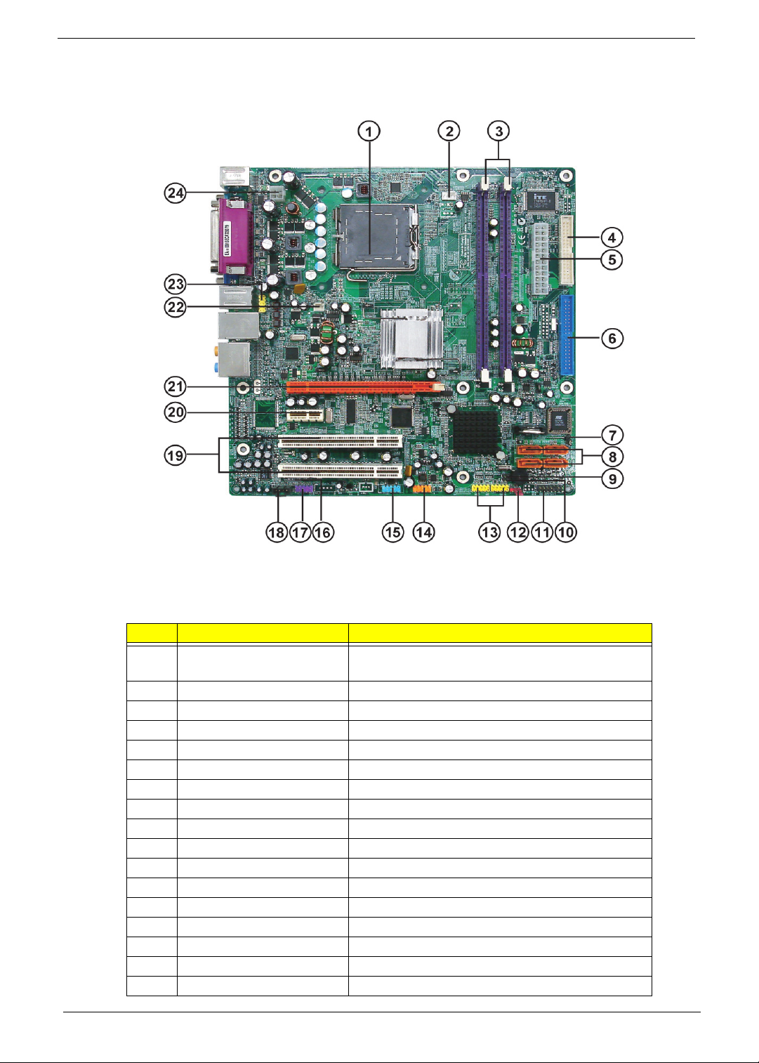
Mainboard Placement
No.
CPU Socket
1
2 CPU_FAN1 CPU cooling fan connector
3 DIMM1~2 DDR2 240 pin SDRAM slots
4 FDD1 Floppy diskette drive connector
5 ATX1 Standard 24pin ATX power connector
6 IDE1 Primary IDE channel
7 BIOS_WP BIOS flash protect jumper
8 SATA1~4 Serial ATA connectors
9 JP2 Jumper
10 JP1 Jumper
11 PANEL1 Front panel switch/LED header
12 CLR_CMOS1 Clear CMOS jumper
13 USB3~4 Front panel USB headers
14 1394A1 Onboard 1394a header
15 COM2 Onboard Serial port header
16 SPDIF SPDIF out header
17 AUDIO2 Front Panel Audio header
Name
LGA775 socket for Intel Core
4/Celeron D CPUs
Description
TM
2 Duo/Pentium D/Pentium
4 Chapter 1
Page 13

No.
18 CD_IN1 Analog audio input connector
19 PCI1~2 32 bit add-on card slot
20 PCIEX1 PCI Express x1 slot
21 PCIEX16 PCI Express x16 slot
22 SYS_FAN1 System fan connector
23 R_USB Front Panel USB header
24 ATX12V1 Auxiliary 4pin power connector
Name
Description
Chapter 1 5
Page 14
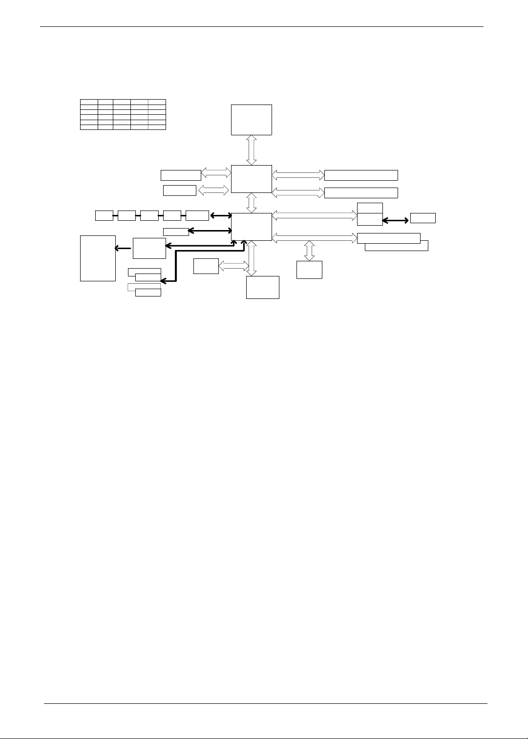
Block Diagram
REQ#
DEVICE
PCI1
PCI2
1394
Mic In
Line Out
Line In
CEN/BAS
SURRON
SID SURRON
PCB : 244 x 244 mm ; 4 layers
INT#
IDSEL
C/D/E/F
17
18
19
Analong Display
RAMDAC: 400MHz
Resolutions Up To 2048x1536@75Hz
USB1
2 ports
D/E/F/G
E
USB2
2 ports
PREQ-0
PREQ-1
PREQ-2
2 ports
Audio Codec
ALC888
SATA1 7Pin
SATA2 7pin
SATA3 7Pin
SATA4 7pin
GNT#
PGNT-0
PGNT-1
PGNT-2
BW : 4.1GB/s @ FSB : 533MHz & Freq : 133MHz
BW : 6.4GB/s @ FSB : 800MHz & Freq : 200MHz
VGA (G only)
PCIEx16
USB4
USBLANUSB3
2 ports
8 ports
IDE1 40pin
BW : 150MB/s
Up to Ultra ATA/100
Two IDE Channel
AC' 97 & Lan I/F
intel
FWH
32pin PLCC
USB V2.0
INTEL
P4 Processor
PSC, Tejas -
LGA 775 pin
INTEL
946GZ
FC-BGA
INTEL
ICH7DH
609pin EBGA
LPC bus
ITE 8718
Super I/O
128pin PQFP
BW : 2GB/s (Support Lsoch)
BW : 133MB/s @Freq : 33MHz
BW : 10.7GB/s @ DDR2 :533/667MHz
DDIMM1: DDR Socket 184P
DDIMM2 : DDR Socket 184P
VIA
6307/8
PCIEX1
PCIEx1 LAN
82573L
PCI1 Slot 120pin @ AD17
PCI2 Slot 120pin @ AD18
USBLAN
RJ45
of
6 Chapter 1
Page 15
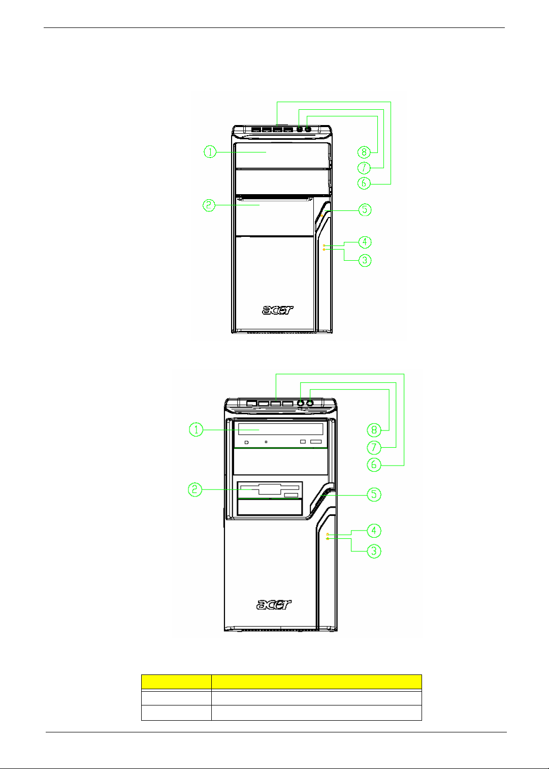
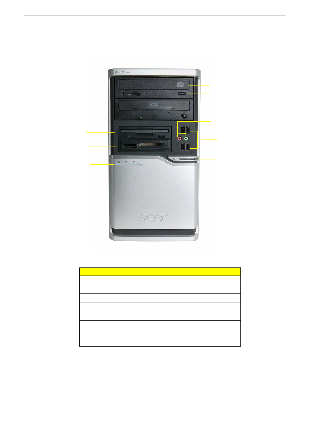
Aspire M3600/M5600 Front Panel
The computer’s front panel consists of the following:
Label Description
1 Optical drive
2 Slide door/ Floppy disk drive
Chapter 1 7
Page 16

Label Description
3LAN LED
4
HDD LED
5 Power Button
6USB ports
7 MIC phone
8 Speaker out
8 Chapter 1
Page 17
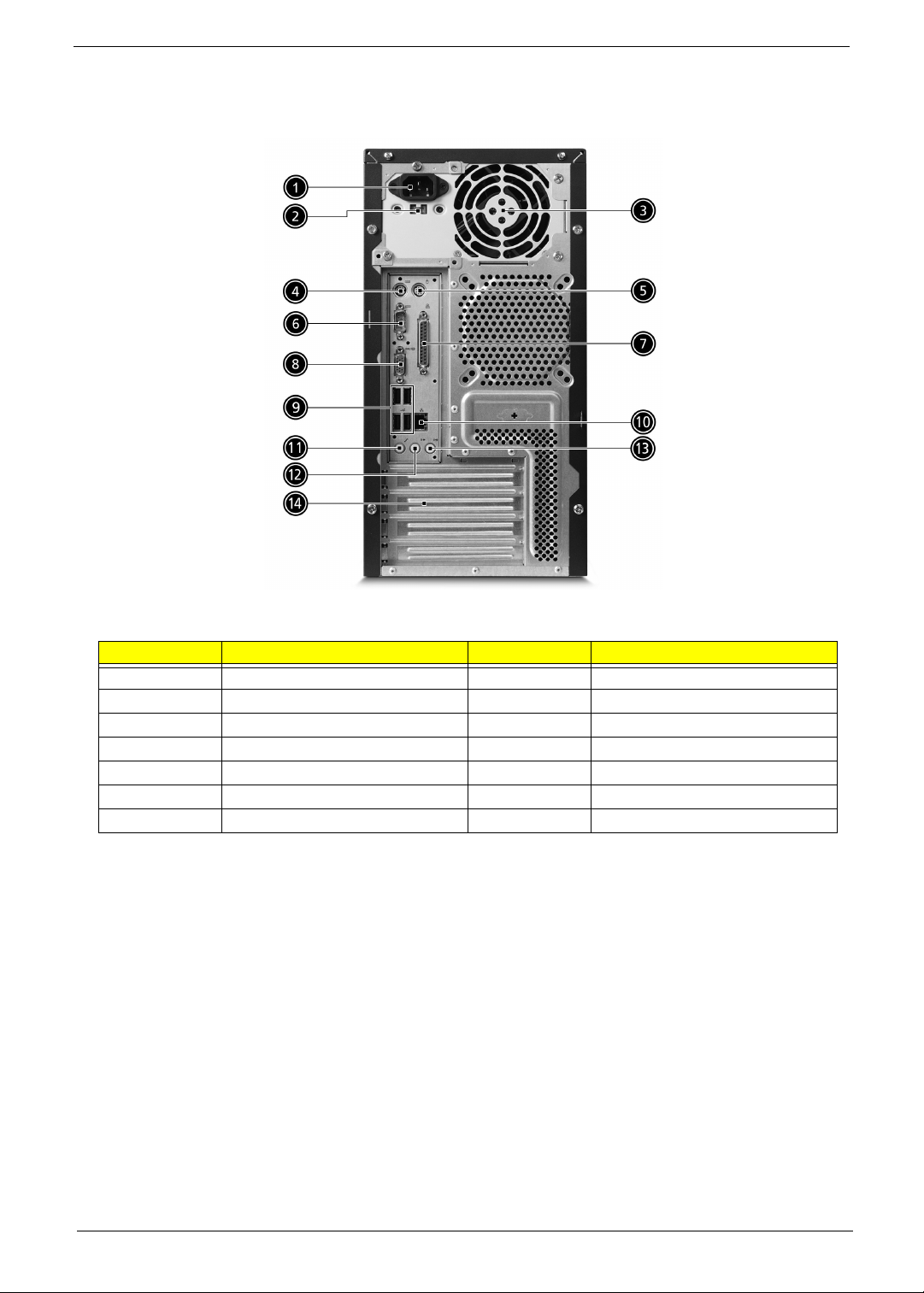
Aspire M3600/M5600 Rear Panel
No. Description No. Description
1 6 audio jacks 2 LAN port
3 USB ports 4 1394 port
5 CRT/LCD port 6 Parallel port
7 HDMI port 8 PS/2 keyboard connector
9 PS/2 mouse connector 10 Power cord port
11 SPDIF bracket 12 SPDIF port
13 Recovery switch holder 14 Lock handle
Chapter 1 9
Page 18
AcerPower M461 Front Panel
8
7
6
5
4
3
2
1
Label Description
1 Power-Button
2USB ports
3 Microphone-in & Speaker-out/Line-out Port
4
5 Optical drive
6 Indicators
7 Card reader
8 HDD
10 Chapter 1
Optical drive eject button
Page 19
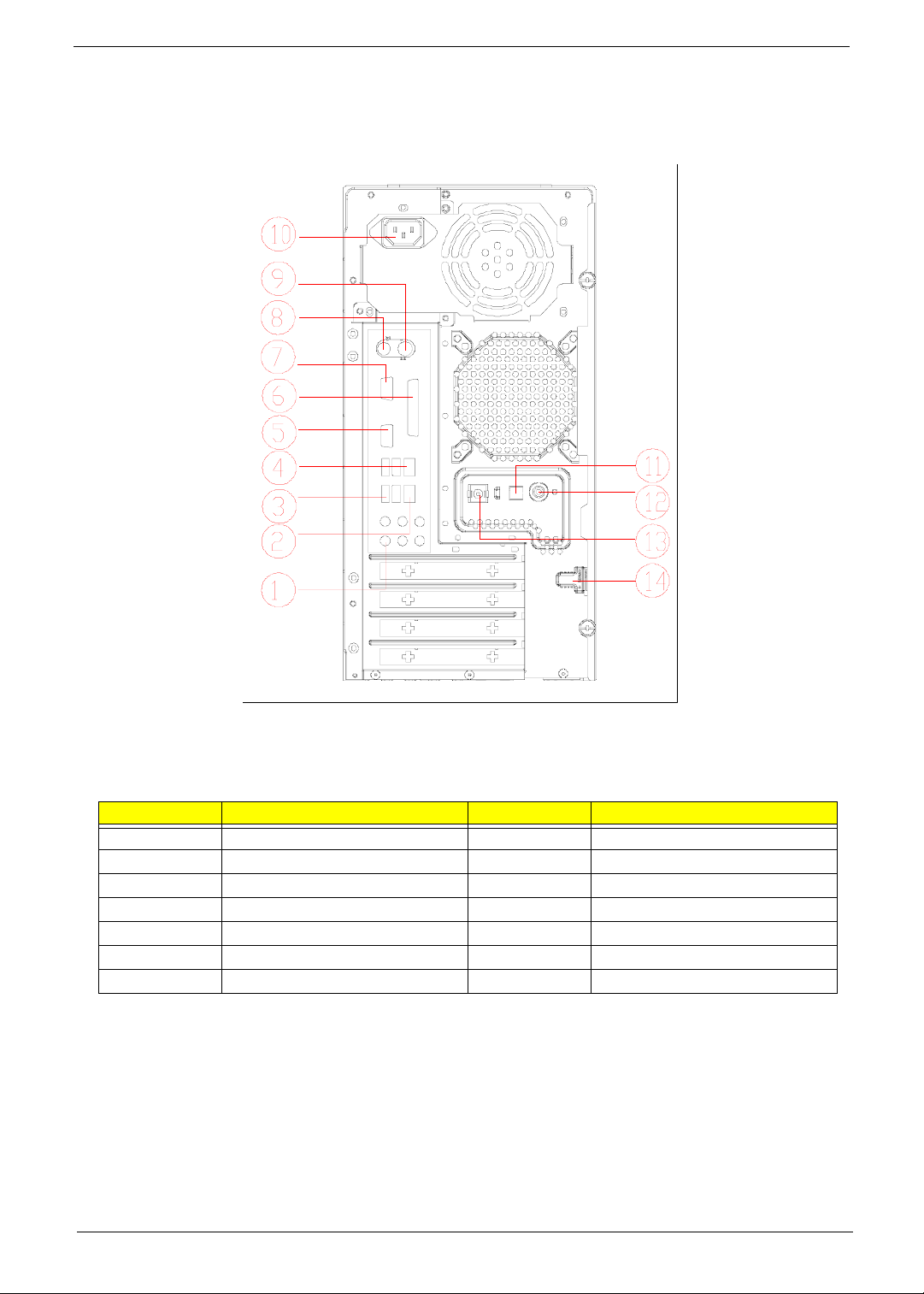
AcerPower M461 Rear Panel
No. Description No. Description
1 Power cord socket 2 Voltage selector switch
3 Fan aperture 4 PS/2 keyboard connector
5 PS/2 mouse connector 6 Serial port
7 Printer connector 8 Monitor connector
9 USB 2.0 ports 10 RJ-45 Ethernet connector
11 Microphone jack 12 Line-out Jack
13 Line-in jack 14 Extension card slots
Chapter 1 11
Page 20
System Peripherals
The Aspire S Series computer consist of the system itself, and system peripherals, like a
mouse, keyboard and a set of speakers (optional). This section provides a brief description of the basic
system peripherals.
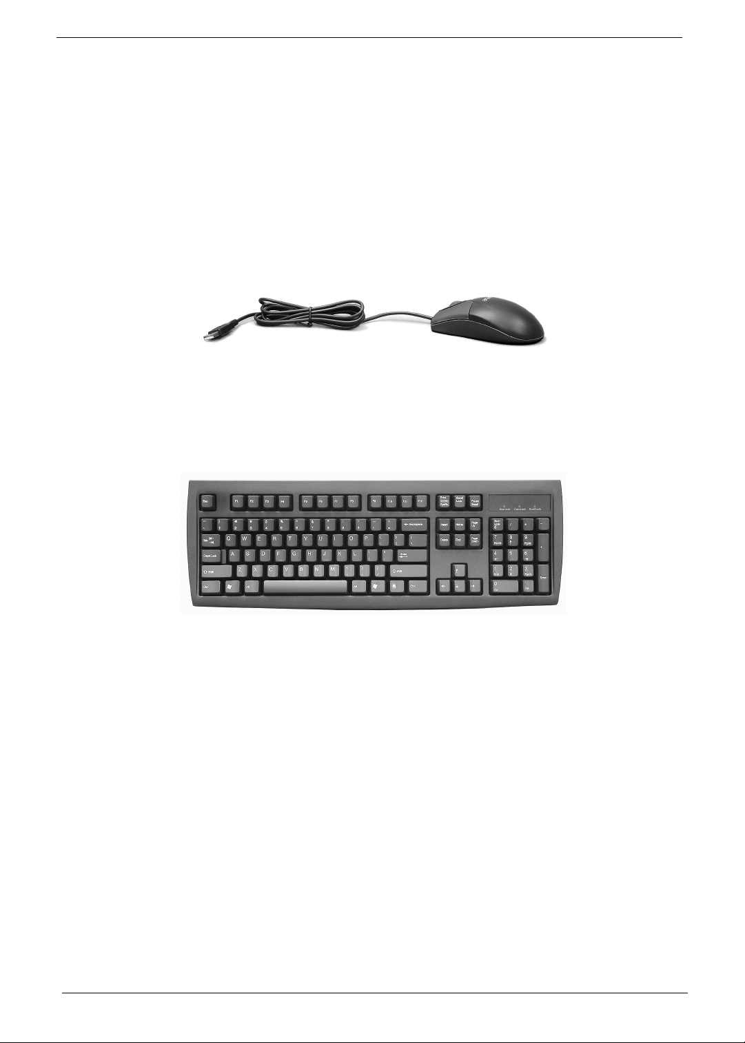
Mouse (PS/2 or USB, manufacturing option)
The included mouse is a standard two-button wheel mouse. Connect the mouse to the PS/2 mouse port or
USB port on the back panel of the system.
Keyboard (PS/2 or USB, manufacturing option)
Connect the keyboard to the PS/2 keyboard port or USB port on the back panel of the system.
12 Chapter 1
Page 21
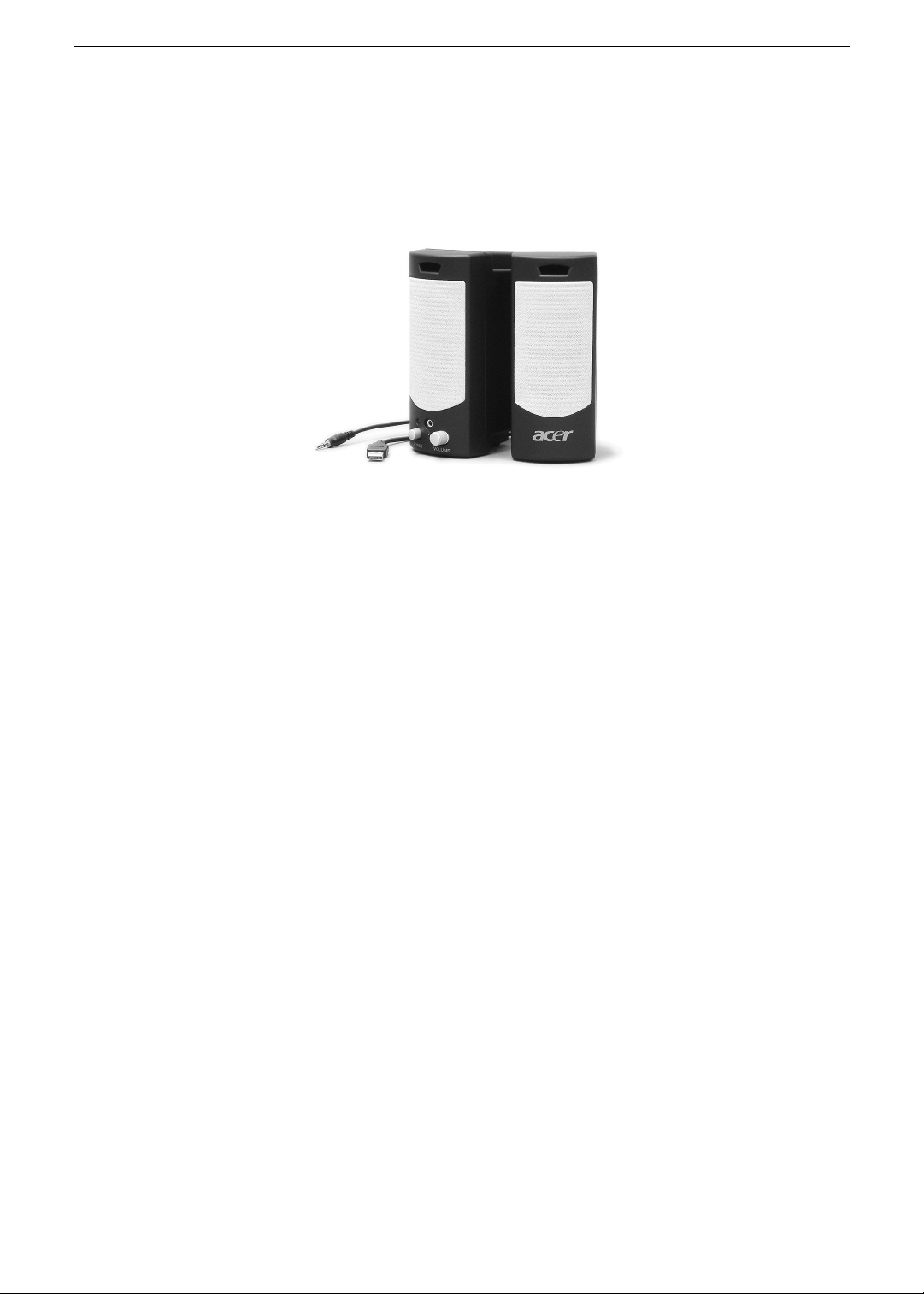
Speakers
Note:
For systems bundled with speakers, before powering on the system, connect the speaker cable to the audio
out (external speaker) port on the back panel of the system.
For more detailed information about the speakers, please refer to the included operating instructions.
NOTE: speakers are optional and the appearance might be different depending on the actual product.
Chapter 1 13
Page 22

Acer eRecovery
Acer eRecovery is a tool to quickly backup and restore the system. Users can create and save a
backup of the current system configuration to hard drive, CD, or DVD.
Acer eRecovery consists of the following functions:
1. Create backup
2. Restore from backup
3. Create factory default image CD
4. Re-install bundled software without CD
5. Change Acer eRecovery password
Create backup
Users can create and save backup images to hard drive, CD, or DVD.
1. Boot to Windows XP
2. Press <Alt>+<F10> to open the Acer eRecovery utility.
3. Enter the password to proceed. The default password is six zeros.
4. In the Acer eRecovery window, select Recovery settings and click Next
5. In the Recovery settings window, select Backup snapshot image and click Next.
6. Select the backup method.
T Use Backup to HDD to store the backup disc image on drive D:.
T Backup to optical device to store the backup disc image on CD or DVD (only available on
systems that include an optical disc burner).
7. After choosing the backup method, click Next.
Follow the instruction on screen to complete the process.
Restore from backup
Users can restore backup previously created (as stated in the Create backup section) from hard drive,
CD, or DVD.
1. Boot to Windows XP.
2. Press <Alt>+<F10> to open the Acer eRecovery utility.
3. Enter the password to proceed. The default password is six zeros.
4. In the Acer eRecovery window, select Recovery actions and click Next.
5. Select the desired restore action and follow the onscreen instructions to complete the restore process.
Create factory default image CD
When the System CD and Recovery CD are not available, you can create them by using this feature.
1. Boot to Windows XP.
2. Press <Alt>+<F10> to open the Acer eRecovery utility.
3. Enter the password to proceed. The default password is six zeros.
4. In the Acer eRecovery window, select Recovery settings and click Next.
5. In the Recovery settings window, select Burn image to disc and click Next.
6. In the Burn image to disc window, select 01. Factory default image and click Next.
14 Chapter 1
Page 23

7. Follow the instructions on screen to complete the process.
Re-install bundled software without CD
Acer eRecovery stores pre-loaded software internally for easy driver and application re-installation.
1. Boot to Windows XP.
2. Press <Alt>+<F10> to open the Acer eRecovery utility.
3. Enter the password to proceed. The default password is six zeros.
4. In the Acer eRecovery window, select Recovery actions and click Next.
5. In the Recovery settings window, select Reinstall applications/drivers and click Next.
6. Select the desired driver/application and follow the instructions on screen to re-install.
At first launch, Acer eRecovery prepares all the needed software and may take few seconds to bring up the
software content window.
Change Password
Acer eRecovery and Acer disc-to-disc recovery are protected by a password that can be changed by
the user. Follow the steps below to change the password in Acer eRecovery.
1. Boot to Windows XP.
2. Press <Alt>+<F10> to open the Acer eRecovery utility.
3. Enter the password to proceed. The default password is six zeros.
4. In the Acer eRecovery window, select Recovery settings and click Next.
5. In the Recovery settings window, select Password: Change Acer eRecovery password and click Next.
6. Follow the instructions on screen to complete the process.
Chapter 1 15
Page 24

Acer disc-to-disc recovery
Restore without a Recovery CD
This recovery process helps you restore the C: drive with the original software content that is installed when
you purchase your notebook. Follow the steps below to rebuild your C: drive. (Your C: drive will be
reformatted and all data will be erased.) It is important to back up all data files before you use this option.
1. Restart the system.
2. While the Acer logo is showing, press <Alt>+<F10> at the same time to enter the recovery process.
3. The message "The system has password protection. Please enter 000000:" is displayed.
4. Enter six zeros and continue.
5. The Acer Recovery main page appears.
6. Use the arrow keys to scroll through the items (operating system versions) and press <Enter> to select.
Multilingual operating system installation
Follow the instructions to choose the operating system and language you prefer when you first power-on the
system.
1. Turn on the system.
2. Acer's multilingual operating system selection menu will pop-up automatically.
3. Use the arrow keys to scroll to the language version you want. Press <Enter> to confirm your selection.
4. The operating system and language you choose now will be the only option for future recovery
operations.
5. The system will install the operating system and language you choose.
16 Chapter 1
Page 25
Hardware Specifications and Configurations
Processor
Item Specification
Type Intel Prescott 775/Conroe
Socket
Speed System bus total up to 20.8GB/s
FSB 800/1600 MHz
BIOS
Item Specification
BIOS code programmer Award
BIOS version v6.0
BIOS ROM type Flash ROM
BIOS ROM size 4MB
BIOS ROM package 32-pin DIP package
Support protocol ACPI 2.0, APM 1.2, SMBIOS 2.3, WFM support, ASD 1.03,
Boot from CD-ROM feature Yes
Support to LS-120 FDD drive Yes
Support to BIOS boot block feature Yes
Socket T LGA 775 pin
PXE boot ROM, PCI 2.3
NOTE: The BIOS can be overwritten/upgraded by using the flash utility.
BIOS Hotkey List
Hotkey Function Description
Delete Enter BIOS Setup Utility Press while the system is booting to
enter BIOS Setup Utility.
Main Board Major Chips
Item Controller
NorthBridge Intel 946GZ
SourthBridge Intel ICH7DH
AGP controller Intel 946GZ
Super I/O controller ITE8718
Audio controller ALC888
LAN controller Intel 82573L
HDD controller ICH7DH
Keyboard controller ITE8718
Chapter 1 17
Page 26
System Memory
Item Specification
Memory slot number 2 slot
Support memory size per socket 256MB to 1GB
Support maximum memory size 2GB
Support memory type DDR2 SDRAM
Support memory interface DDR2 667/533
Support memory voltage 1.8V
Support memory module package 240-pin DIMM
Support to parity check feature Yes
Support to Error Correction Code (ECC)
feature
Memory module combinations You can install memory modules in any combination as
NOTE: Dual channel should be enabled always when plug-in 2 same memory size DDRII memory module.
Cache Memory
Item Specification
First-Level Cache Configurations
Cache function control Enable/Disable by BIOS Setup
Second-Level Cache Configurations
L2 Cache RAM type PBSRAM
L2 Cache RAM size up to 1MB per core(exclusive)
L2 Cache RAM speed One-half the processor core clock frequency
L2 Cache function control Enable/Disable by BIOS Setup
L2 Cache scheme Fixed in write-back
ECC checking with double-bit detect and single-bit
correct
long as they match the specifications.
Video Interface
Item Specification
Video controller Intel ICH7DH
Video controller resident bus PCIE
Video Interface x16
AGP Slot 1
Audio Interface
Item Specification
Audio controller ICH7DH
Audio controller Type AC’97, ALC888
Audio Channel 7.1ch
Audio function control Enable/disable by BIOS Setup
18 Chapter 1
Page 27
Audio Interface
Item Specification
Mono or stereo Stereo
Resolution support up to 24 bit
Compatibility Sound Blaster Pro/16 compatible
Mixed digital and analog high performance chip
Enhanced stereo full duplex operation
High performance audio accelerator and AC’97 support
Full native DOS games compatibility
Virtual FM enhances audio experience through real-time FM-to-
Wavetable conversion
MPU-401(UART mode) interface for wavetable synthesizers and
MIDI devices
Integrated dual game port
Meets AC’97and WHQL specifications
Music synthesizer Yes, internal FM synthesizer
Sampling rate DACs: 44.1k/48k/96k/192k Hz
ADCs: 44.1k/48k/96k Hz
MPU-401 UART support Yes
Microphone jack Supported
Headphone jack Supported
IDE Interface
Item Specification
IDE controller Intel ICH7DH
IDE controller resident bus PCI bus
Number of IDE channel 1
Support IDE interface E-IDE (up to PIO mode-4 and Ultra DMA 33/66/100/133), ANSIS
ATA rev.3.0 ATAPI
Support bootable CD-ROM Yes
Floppy disk drive Interface
Item Specification
Floppy disk drive controller ITE8718
Floppy disk drive controller resident
bus
Support FDD format should support 1.44MB/3mode 3.5” Devices
LPC bus
Chapter 1 19
Page 28
Parallel Port
Item Specification
Parallel port controller ITE8718
Parallel port controller resident bus ISA bus
Number of parallel ports 1
Support ECP/EPP Bi-directional SPP / ECP / EPP V1.7&V1.9
Connector type 25-pin D-type female connector
Parallel port function control Enable/disable by BIOS Setup
Serial Port
Item Specification
Serial port controller ITE8718
Serial port controller resident bus ISA bus
Number of serial port 2
16550 UART support Yes
Connector type 9-pin D-type female connector
Features Support IrDA1.0/ASKIR protocols, smart card reader protocols
USB Port
Item Specification
Universal HCI USB 2.0
USB Class Support legacy keyboard for legacy mode
USB Number support up to 8 ports
Environmental Requirements
Item Specifications
Temperature
Operating +5°C ~ +35°C
Non-operating -20 ~ +60°C (Storage package)
Humidity
Operating 15% to 80% RH
Non-operating 10% to 90% RH
Vibration
Operating (unpacked) 5 ~ 500 Hz:2.20g RMS random, 10 minutes per axis in all 3 axes
5 ~500 Hz: 1.09g RMS random, 1 hour per axis in all 3 axes
Power Management
Devices
Power Button Enabled Enabled Enabled Disabled
S1
(Idle)
S3
(Suspend to
RAM)
S4
(Suspend to
DIsk)
S5
(Shut Down)
20 Chapter 1
Page 29

Power Management
Devices
USB Keyboard Enabled Enabled Disabled N/A
LAN Disabled Disabled Disabled Disabled
RTC Disabled Enabled Disabled Disabled
Modem (Ring) Disabled Disabled Disabled N/A
S1
(Idle)
S3
(Suspend to
RAM)
S4
(Suspend to
DIsk)
S5
(Shut Down)
Chapter 1 21
Page 30

Power Management Function (ACPI support function)
Device Standby Mode
T Independent power management timer for hard disk drive devices
(0-15 minutes, time step=1 minute).
T Hard disk drive goes into Standby mode (for ATA standard interface).
T Disable V-sync to control the VESA DPMS monitor.
T Resume method: device activated (Keyboard for DOS, keyboard & mouse for Windows).
T Resume recovery time: 3-5 sec.
Global Standby Mode
T Global power management timer (2-120 minutes, time step=10 minute).
T Hard disk drive goes into Standby mode (for ATA standard interface).
T Disable H-sync and V-sync signals to control the VESA DPMS monitor.
T Resume method: Return to original state by pushing external switch button, modem ring in,
keyboard and mouse for APM mode.
T Resume recovery time: 7-10 sec.
Suspend Mode
T Independent power management timer (2-120 minutes, time step=10 minutes) or pushing external
switch button.
T CPU goes into SMM.
T CPU asserts STPCLK# and goes into the Stop Grant State.
T LED on the panel turns amber colour.
T Hard disk drive goes into SLEEP mode (for ATA standard interface).
T Disable H-sync and V-sync signals to control the VESA DPMS monitor.
T Ultra I/O and VGA chip go into power saving mode.
T Resume method: Return to original state by pushing external switch button, modem ring in,
keyboard and mouse for APM mode.
T Return to original state by pushing external switch button, modem ring in and USB keyboard for
ACPI mode.
ACPI
T ACPI specification 1.0b.
T S0, S1, S3 and S5 sleep state support.
T On board device power management support.
T On board device configuration support.
22 Chapter 1
Page 31

Chapter 2
System Utilities
About the Setup Utility
The computer uses the latest Award BIOS with support for Windows Plug and Play. The CMOS chip on the
main board contains the ROM setup instructions for configuring the main board BIOS.
The BIOS Setup Utility displays the system’s configuration status and provides you with options to set system
parameters. The parameters are stored in battery-backed-up CMOS RAM that saves this information when the
power is turned off. When the system is turned back on, the system is configured with the values you stored in
CMOS.
The BIOS Setup Utility enables you to configure:
T Hard drives, diskette drives and peripheral
T Video display type and display options
T Password protection from unauthorized use
T Power Management features
The settings made in the Setup Utility affect how the computer performs. Before using the Setup Utility, ensure
that you understand the Setup Utility options.
The Standard Configuration
A standard configuration has already been set in the Setup Utility. However, we recommend that you read this
chapter in case you need to make any changes in the future.
This Setup Utility should be used:
T when changing the system configuration
T when a configuration error is detected and you are prompted to make changes to the Setup Utility
T when trying to revolve IRQ conflicts
T when making changes to the Power Management configuration
Chapter 2 23
Page 32

Entering the Setup Utility
When you power on the system, BIOS enters the Power-On Self-Test (POST) routines. POST is a series of
built-in diagnostics performed by the BIOS. After the POST routines are completed, the following message
appears: Press DEL to enter SETUP
Press the delete key to have access to the BIOS Setup Utility.
NOTE: If the message disappears before you respond and you still want to enter Setup, restart the system by
turning it OFF and On. You may also restart the system by simultaneously pressing [Ctrl + Alt + Delete].
Product Information
f
Standard CMOS Features
f
Advanced BIOS Features
f
Advanced Chipset Features
f
Integrated Peripherals
f
Power Management Setup
f
PnP/PCI Configurations
f
Esc: Quit
F10: Save & Exit Setup
BIOS Navigation Keys
The BIOS navigation keys are listed below:
T ESC: Exits the current menu.
T : Scrolls through the items on a menu.
T +/-/PU/PD: Modifies the selected field’s values.
T F10: Saves the current configuration and exits setup.
T F1: Displays a screen that describes all key functions.
T F5: Loads previously saved values to CMOS.
T F7: Loads an optimum set of values for peak performance.
PC Health Status
f
Frequency/Voltage Control
f
Load Optimized Defaults
Set Supervisor Password
Set User Password
Save & Exit Setup
Exit Without Saving
mnlk
Time, Date, Hard Disk Type...
: Select Item
Using BIOS
When you start the Setup Utility, the main menu will appear. The main menu of the Setup Utility displays a list
of the options that are available. A highlight indicates which options is currently selected. Use the cursor arrow
keys to move the highlight to other options. When an option is highlighted, execute the option by pressing
<Enter>.
Some options lead to pop-up dialog box that prompt you to verify that you want to execute that option. Other
options lead to dialog boxes that prompt you for information.
Some options (marked with a triangle) lead to submenus that enable you to change the values for that option.
Use the cursor arrow keys to scroll through the items in the submenu.
In this chapter, default values are enclosed in parenthesis. Submenu items are denoted by a triangle.
24 Chapter 2
Page 33

Product Information
This option displays basic information about the system.
Phoenix-AwardBIOS CMOS Setup Utility
Product Information
Product Name Aspire/M5600/AM3600
System S/N
Main Board ID E946GZ
Main Board S/N
System BIOS Version R01-A1
SMBIOS Version 2.4
BIOS Release Date Apr 30, 2007
: Move Enter: Select +/-/PU/PD:Value F10:Save ESC:Exit F1: General Help
mnlk
F5:Previous Values F7:Optimized Defaults
T Product Names: Displays the model name of your system.
T System S/N: Displays your system’s serial number.
T Main Board ID: Displays the ID number of the main board.
T Main Board S/N: Displays the serial number of the main board.
T System BIOS Version: Specifies the version of the BIOS utility.
T SMBIOS Version: The System Management Interface (SM) BIOS allows you to check your
Item Help
Menu Level
f
system hardware components without actually opening your system. Hardware checking is done
via software during start up. This parameter specifies the version of the SMBIOS utility installed in
your system.
T BIOS Release Date: Displays the BIOS latest release date.
Chapter 2 25
Page 34

Standard CMOS Features
Select Standard CMOS Features from the main menu to configure some basic parameters in your system.
Phoenix-AwardBIOS CMOS Setup Utility
Standard CMOS Features
Date (mm:dd:yy)
Time (hh:mm:ss) 9 : 33 : 26
f
IDE Channel 0 Master [ None]
f
IDE Channel 0 Slave [LITE-ON DVD SOHD-16F]
f
IDE Channel 1 Master [ None]
f
IDE Channel 1 Slave [ None]
f
IDE Channel 2 Master [ST3160612AS]
f
IDE Channel 2 Slave [ None]
f
IDE Channel 3 Master [ None]
f
IDE Channel 3 Slave [ None]
Video [EGA/VGA]
Halt On [
Base Memory 640K
Extended Memory 65535K
Total Memory 1024K
mnlk
T Date and Time: This item shows the current date and time set on the computer. If you are running
: Move Enter: Select +/-/PU/PD:Value F10:Save ESC:Exit F1: General Help
F5:Previous Values F7:Optimized Defaults
Sun, Jan 1 2006
All , But Keyboard]
Item Help
Menu Level
Change the day, month,
year and century
f
a Windows OS, these items are automatically updated whenever you make changes to the
Windows Date and Time Properties utility.
T IDE Devices (none): Your computer has one IDE channel and can be installed with one or two
devices (Master and Slave). Use this item to configure each device on the IDE channel. This main
board features four SATA connectors supporting four SATA drives. SATA refers to Serial ATA
(Advanced Technology Attachment), the standard interface for the IDE hard drives which are
currently used in most PCs.
Phoenix-AwardBIOS CMOS Setup Utility
IDE Channel 0 Maser
IDE HDD Auto-Detection [Press Enter]
IDE Channel 0 Master [Auto]
Access Mode [Auto]
Capacity 0 MB
Cylinder 0
Head 0
Precomp 0
Landing Zone 0
Sector 0
mnlk
: Move Enter: Select +/-/PU/PD:Value F10:Save ESC:Exit F1: General Help
F5:Previous Values F7:Optimized Defaults
Item Help
Menu Level
To auto-detect the
HDD’s size, head... on
this channel
ff
26 Chapter 2
Page 35

T IDE HDD Auto-Detection: Press <Enter> while this item is highlighted to prompt the Setup
Utility to automatically detect and configure an IDE device on the IDE channel.
NOTE: Press <Enter> while this item is highlighted to prompt the Setup Utility to automatically detect and
configure an IDE device on the IDE channel.
T IDE Channel 0/1/2/3 Master/Slave IDE/Extended IDE Drives (Auto): Leave this item Auto to
enable the system to automatically detect and configure IDE devices on the channel. If it fails
to find a device, change the value to Manual and then manually configure the drive by
entering the properties of the drive in the items described below. Please note that if you
choose IDE channel 2/3 Master, the item may change to Extended IDE drive.
T Access Mode: This item defines ways that can be used to access IDE hard disks such as
LBA (Large Blocking Addressing). Leave this value Auto and the system will automatically
decide the fastest way to access the hard disk drive. If you choose IDE channel 2/3 Master,
the item only has Large and Auto.
T Video (EGA/VGA): This item defines the video mode of the system. This main board has a built-in
VGA graphics system. You must leave this item at the default value.
T Halt On (All but Keyboard): This item defines the operation of the system POST (Power-On Self-
Test) routine. You can use this item to select which types of errors in the POST are sufficient to
halt the system.
T Base Memory, Extended Memory, and Total Memory: This items are automatically detected by
the system at start up time. These are display-only fields. You can not make changes to these
fields.
Chapter 2 27
Page 36

Advanced BIOS Features
The following screen shows the Advanced BIOS Features.
Phoenix-AwardBIOS CMOS Setup Utility
Advanced BIOS Features
CPU Feature [Press Enter]
f
Hard Disk Boot Priority [Press Enter]
f
Virus Warning [Disabled]
CPU L1 & L2 Cache [Enabled]
CPU L3 Cache [Enabled]
Quick Power On Self Test [Enabled]
First Boot Device [N/A]
Second Boot Device [Hard Disk]
Third Boot Device [CDROM]
Boot Other Device [Enabled]
Boot Up NumLock Status [On]
Gate A20 Option [Fast]
Typematic Rate Setting [Disabled]
Typematic Rate (Chars/Sec0 6
x
Typematic Delay (Msec) 250
x
Security Option [Setup]
APIC Mode [Enabled]
MPS Version Control For OS [1.4]
OS Select For DRAM > 64MB [Non-OS2]
HDD S.M.A.R.T. Capability [Diasabled]
: Move Enter: Select +/-/PU/PD:Value F10:Save ESC:Exit F1: General Help
mnlk
F5:Previous Values F7:Optimized Defaults
Item Help
Menu Level
f
T CPU Features (Press Enter): Please note that this function is only available for Prescott CPUs.
Scroll to this item and press <Enter> to view the following screen.
Phoenix-AwardBIOS CMOS Setup Utility
CPU Feature
Thermal Management Thermal Monitor 1
Delay Prior to Thermal [16 Min]
Limit CPUID MaxVal [Disabled]
CPU Enhanced Halt (C1E) [Auto]
Execute Disable Bit [Enabled]
Intel (R) SpeedStep (tm) Tech. [Enabled]
: Move Enter: Select +/-/PU/PD:Value F10:Save ESC:Exit F1: General Help
mnlk
F5:Previous Values F7:Optimized Defaults
Item Help
Menu Level
ff
T Delay Prior to Thermal (16 Min): This item enables you to set the delay time before the CPU
28 Chapter 2
Page 37

enters auto thermal mode.
T Thermal Management (Thermal Monitor 1): This item displays CPU’s temperature and
enables you to set a safe temperature to Prescott CPU.
T TM2 Bus Ratio (12X): This item represents the frequency (bus ratio) of the throttled
performance state that will be initiated when the on-die sensor goes from not hot to hot.
T TMS Bus VID (1.2000V): This item represents the voltage of the throttled performance state
that will be initiated when the on-die sensor goes from not hot to hot.
T Limit CPUID MaxVal (Disabled): This item can support Prescott CPUs for old OS. Please
note that under NT4.0, it must be set Enabled while under WinXP, it must be set Disabled.
T Execute Disable Bit (Enabled): This item is a security feature that helps you protect your
CPU and operating system against malicious software executing code. This item is available
when CPU supports the feature.
T Hard Disk Boot Priority (Press Enter): Scroll to this item and press <Enter> to view the following
screen.
Phoenix-AwardBIOS CMOS Setup Utility
Hard Disk Boot Priority
1. Ch2 M. : ST3160812AS
2. Bootable Add-in Cards
Item Help
Menu Level
Use < > or < > to
ff
m
n
select a device, then
press <+> to move it
up, or <-> to move it
down the list. Press
<ESC> to exit this
menu.
mnlk
T Virus Warning (Disabled): This item is used to enable or disable virus warning function.
T CPU L1 & L2 Cache (Enabled): All processors that can be installed in this main board use internal
: Move Enter: Select +/-/PU/PD:Value F10:Save ESC:Exit F1: General Help
F5:Previous Values F7:Optimized Defaults
level 1 (L1) and external level 2 (L2) cache memory to improve performance. Leave this item at the
default value for better performance.
T Hyper-Threading Technology (Enabled): This item is only available when the chipset supports
Hyper-Threading and you are using a Hyper-Threading CPU.
T Quick Power On Self Test (Enabled): Enable this item to shorten the power on testing (POST)
and have your system start up faster. You might like to enable this item after you are confident that
your system hardware is operating smoothly.
T First/Second/Third Boot Device (Floppy/Hard Disk/CD ROM): Use these three items to select
the priority and order of the devices that your system searches for an operating system at start-up
time.
T Boot Other Device (Enabled): When enabled, the system searches all other possible locations
for an operating system if it fails to find one in the devices specified under the First, Second and
Third boot devices.
Chapter 2 29
Page 38

T Boot Up NumLock Status (On): This item defines if the keyboard NumLock key is active when
your system is started.
T Gate A20 Option (Fast): This item defined how the system handles legacy software that was
written for an earlier generation of processors. Leave this item at the default value.
T Typematic Rate Setting (Disabled): If this item is enabled, you can use the following two items to
set the typematic rate and the typematic delay settings for your keyboard.
T Typematic Rate (Chars/Sec): Use this item to define how many characters per second are
generated by held-down key.
T Typematic Delay (Msec): Use this item to define how many milliseconds must elapse before
a held-down key begins generating repeat characters.
T Security Option (Setup): If you have installed password protection, this item defines if the
password is required at system start up, or if it is only required when a user tries to enter the Setup
Utility.
T APIC Mode (Enable): This item allows you to enable or disable the APIC (Advanced
Programmable Interrupt Controller) mode. APIC provides symmetric multi-processing (SMP) for
systems, allowing support for up to 60 processors.
T MPS Version Control For OS (1.4): This item displays MPS version control for OS.
T OS Select For DRAM > 64MB (Non-OS2): This item is only required if you have installed more
than 64MB of memory and you are running the OS/2 operating system. Otherwise, leave this item
at the default.
T HDD S.M.A.R.T Capability (Disabled): When you enable HDD SMART (Self-Monitoring, Analysis
and Reporting Technology) Capability, these new BIOSes will automatically check the hard disk’s
SMART status at boot-up.
T Report No FDD For WIN 95 (Disabled): Set this item to the default if you are running a system
with no floppy drive and using Windows 95. This ensures compatibility with the Window 95 logo
certification.
T Silent Boot (Enabled): If enabled, BIOS will show a full screen logo at boot. If disabled, BIOS will
set the initial display mode to BIOS and show the diagnostic POST screen at boot.
T Small Logo (EPA) Show (Disabled): This item enabled or disables the display of the EPA logo
during boot.
T Configuration Table (Disabled): Use this item to show summary screen.
30 Chapter 2
Page 39

Advanced Chipset Features
These items define critical timing parameters of the main board. You should leave the items on this page at
their default values unless you are very familiar with the technical specifications of your system hardware. If
you change the values incorrectly, you may introduce fatal errors or recurring instability into your system.
Phoenix-AwardBIOS CMOS Setup Utility
Advanced Chipset Feature
System BIOS Cacheable [Enabled]
Video BIOS Cacheable [Disabled]
Memory Hole At 15M-16M [Disabled]
PCI Express Root Port Func [Press Enter]
f
** VGA Setting **
PEG/Onchip VGA Control [Auto]
On-Chip Frame Buffer Size [ 8MB]
DVMT Mode [DVMT]
DVMT/FIXED Memory Size [ 128MB]
mnlk
T System BIOS Cacheable (Enable): This item allows the system to be cached in memory for
T Video BIOS Cacheable (Disabled): This item aims to further boost the performance of a
T Memory Hole At 15M-16M (Disable): In order to improve performance, certain space in memory
: Move Enter: Select +/-/PU/PD:Value F10:Save ESC:Exit F1: General Help
F5:Previous Values F7:Optimized Defaults
faster execution. Enable this item for better performance.
shadowed video BIOS by caching it using the processor’s Level 2 cache.
can be reserved for ISA cards. This memory must be mapped into the memory space below
16MB.
Item Help
Menu Level
f
Chapter 2 31
Page 40

T PCI Express Root Port Func (Press Enter): Scroll to this item and press <Enter> to view the
following screen.
Phoenix-AwardBIOS CMOS Setup Utility
PCI Express Root Port Func
PCI Express Port 1 [Auto]
Item Help
PCI Express Port 2 [Auto]
PCI Express Port 3 [Auto]
PCI Express Port 4 [Auto]
Menu Level
f
f
PCI Express Port 5 [Auto]
PCI Express Port 6 [Auto]
PCI-E Compliancy Mode [v1.0a]
mnlk
T PEG/Onchip VGA Control (Auto): This item allows you to control the PEG or on-chip VGA.
T On-Chip Frame Buffer Size (8MB): This item controls the amount of system memory that is
: Move Enter: Select +/-/PU/PD:Value F10:Save ESC:Exit F1: General Help
F5:Previous Values F7:Optimized Defaults
T PCI-E Compliancy Mode (1.0a): This item allows you to select the PCI-E Compliancy mode.
allocated to the integrated graphics processor when the system boots up.
T DVMT Mode (DVMT): this item allows you to select the DVMT operating mode.
T PEG/On-chip VGA Control (128MB): This item allows you to adjust the shared memory size.
32 Chapter 2
Page 41

Integrated Peripherals
These options display items that define the operation of peripheral components on the system’s input/output
ports.
Phoenix-AwardBIOS CMOS Setup Utility
Integrated Peripherals
OnChip IDE Device [Press Enter]
f
Onboard Device [Press Enter]
f
SuperIO Device [Press Enter]
f
mnlk
T OnChip IDE Device (Press Enter): Scroll to this item and press <Enter> to view the following
: Move Enter: Select +/-/PU/PD:Value F10:Save ESC:Exit F1: General Help
F5:Previous Values F7:Optimized Defaults
Item Help
Menu Level
ff
screen.
Phoenix-AwardBIOS CMOS Setup Utility
OnChip IDE Device
IDE HDD Block Mode [Enabled]
IDE DMA transfer access [Enabled]
On-Chip Primary PCI IDE [Enabled]
IDE Primary Master PIO [Auto]
IDE Primary Slave PIO [Auto]
IDE Primary Master UDMA [Auto]
IDE Primary Slave UDMA [Auto]
On-Chip Secondary PCI IDE [Enabled]
IDE Secondary Master PIO [Auto]
IDE Secondary Slave PIO [Auto]
IDE Secondary Master UDMA [Auto]
IDE Secondary Slave UDMA [Auto]
*** On-Chip Serial ATA Setting ***
SATA Mode AHCI
OnChip Serial ATA [Enabled]
x
: Move Enter: Select +/-/PU/PD:Value F10:Save ESC:Exit F1: General Help
mnlk
F5:Previous Values F7:Optimized Defaults
T IDE HDD Block Mode (Enabled): If your IDE hard drive supports block mode, select Enabled
Item Help
Menu Level
If your IDE hard drive
supports block mode
select Enabled for
automatic detection of
the optimal number of
block read/writes per
sector the drive can
support
ff
for automatic detection of the optimal number of block read/write per sector that the drive can
support.
Chapter 2 33
Page 42

T IDE DMA transfer access (Enabled): This item allows you to enable the transfer access of
the IDE DMA then burst onto the PCI bus and nonburstable transactions do not.
T OnChip Primary/Secondary PCI IDE (Enabled): Use these items to enable or disable the
PCI IDE channels that are integrated on the main board.
T Primary/Secondary Master/Slave UltraDMA (Auto): Enable this item if you plan to use a
mouse connected through the USB port in a legacy operating system (such as DOS) that
does not support Plug and Play.
T OnChip Serial ATA (Enabled): Use this item to enable or disable the on-chip serial ATA.
T Onboard Device (Press Enter): Scroll to this item and press <Enter> to view the following screen.
Phoenix-AwardBIOS CMOS Setup Utility
Onboard Device
USB Controller [Enabled]
Item Help
USB 2.0 Support [Enabled]
USB Keyboard Support [Disabled]
Menu Level
ff
USB Mouse Support [Disabled]
Onboard Audio Device [Enabled]
Onboard IEEE1394 Controller [Enabled]
Onboard GLAN Device [Enabled]
Onboard Lan Boot ROM [Enabled]
mnlk
T USB Controller (Enabled): Enables or disables the onboard USB controller. We recommend
: Move Enter: Select +/-/PU/PD:Value F10:Save ESC:Exit F1: General Help
F5:Previous Values F7:Optimized Defaults
users keep the default value. It might cause the USB devices not to work properly if you
disable this item.
T USB 2.0 Support (Enabled): This item enables or disables the onboard USB 2.0 controller.
T USB Keyboard Support (Disabled): Enable this item if you want to use a keyboard
connected through the USB port in a legacy operating system (such as Dos) that does not
support Plug and Play.
T USB Mouse Support (Enabled): Enable this item if you want to use a mouse connected
through the USB port in a legacy operating system (such as DOS) that does not support Plug
and Play.
T Onboard Audio Device (Enabled): Use this item to enable or disable the onboard audio
device.
T Onboard IEEE 1394 Controller (Enabled): This item allows you to control the onboard IEEE
1394 controller.
T Onboard GLAN Device (Enabled): Use this item to enable or disable the onboard GLAN
device.
T Onboard Lan Boot ROM (Enabled): Use this item to enable or disable the booting from the
onboard LAN or a network add-in card with a remote boot TOM installed.
34 Chapter 2
Page 43

T Super IO Device (Press Enter): Scroll to this item and press <Enter> to view the following screen.
Phoenix-AwardBIOS CMOS Setup Utility
Onboard Serial Port 1 [3F8/IRQ4]
Onboard Serial Port 2 [2F8/IRQ3]
Onboard Parallel Port [378/IRQ7]
Parallel Port Mode [SPP]
ECP Mode Use DMA 3
x
CIR Port Address [Disabled]
x
CIR Port IRQ 11
: Move Enter: Select +/-/PU/PD:Value F10:Save ESC:Exit F1: General Help
mnlk
F5:Previous Values F7:Optimized Defaults
T Onboard FDC Controller (Enabled): Select Enabled if your system has a floppy disk
Super IO Device
Item Help
Menu Level
ff
controller (FDC) installed on the main board. If you install an add-in FDC or the system has no
floppy drive, select Disabled in this field.
T Onboard Serial Port 1/2 (3F8/IRQ4/2F8/IRQ3): These options are used to assign the I/O
address and interrupt request (IRQ) for onboard serial port 1 and port 2.
T Onboard Parallel Port (378/IRQ7): This option is used to assign the I/O address and
interrupt request (IRQ) for the onboard parallel port.
T Parallel Port Mode (SSP): Enables you to set the data transfer protocol for your parallel port.
There are four options: SPP (Standard Parallel Port), EPP (Enhanced Parallel Port), ECP
(Extended Capabilities Port), and ECP + EPP.
T ECP Mode Use DMA (3): When the onboard parallel port is set to ECP mode, the parallel port
can use DMA 3/1.
Chapter 2 35
Page 44

Power Management Setup
3
3
3
This option lets you control system power management. The system has various power-saving modes
including powering down the hard disk, turning off the video, suspending on RAM, and software power down
that allows the system to be automatically resumed by certain events.
Phoenix-AwardBIOS CMOS Setup Utility
Power Management Setup
f
PCI Express PM Function [Press Enter]
ACPI Function [Enabled]
ACPI Suspend Type [S3(STR)]
Run VGABIOS if S3 Resume [Auto]
Soft-Off by PWR-BTTN [Delay 4 Sec.]
Resume by PCI PME [Enabled]
Resume by Ring [Enabled]
S3 resume by USB devices [Enabled]
Resume By PS2 MS (S3) [Enabled]
Resume by PS2 KB (S3) [Enabled]
Power on After Power Fail [Former-Sts]
Resume by Alarm [Disabled]
Date (of Month) Alarm 0
x
Time (hh:mm:ss) Alarm 0: 0: 0
x
*** Reload Global Timer Events ***
Primary IDE 0 [Disabled]
Primary IDE 1 [Disabled]
Secondary IDE 0 [Disabled]
: Move Enter: Select +/-/PU/PD:Value F10:Save ESC:Exit F1: General Help
mnlk
F5:Previous Values F7:Optimized Defaults
T ACPI Function (Enabled): Use this item to enable or disable the ACPI function.
T ACPI Suspend Type (S3(STR)): Use this item to define how your system suspends. In the default,
2
2
2
f
f
Menu Level
Item Help
f
S3 (STR), the suspend mode is a suspend on RAM, i.e., the system shuts down with the exception
of a refresh current to the system memory.
T Run VGA BIOS if S3 Resume (Auto): This item allows the system to initialize the VGA BIOS from
S3 (Suspend on RAM) sleep state.
T Power Management (User Define): Use this item to enable or disable a power management
scheme. If you enable power management, you can use the items below to set the power
management operation.
T Video Off Method: This item defines how the video is powered down to save power. This item is
set for DPMS (Display Power Management Software) by default.
T Suspend Type (Stop Grant): If this item is set to the default Stop Grant, the CPU will go into Idle
Mode during power saving power.
T Modem Use IRQ (3): If you want an incoming call on a modem to automatically resume the
system from a power-saving mode, use this item to specify the interrupt request line (IRQ) that is
used by the modem. You might have to connect the fax/modem to the main board Wake On
Modem connector for the feature to work.
T Suspend Mode (Disabled): This item allows you to enable or disable the suspend mode.
T HDD Power Down (Disabled): The IDE hard drive will spin down if it is not accessed within a
specified length of time.
T Soft-Off by PWR-BTTN (Instant-Off): Under ACPI (Advanced Configuration and Power
Management Interface) you can create a software power down. In a software power down, the
system can be resumed by Wake Up Alarms. This item lets you install a software power down that
is controlled by the power button on your system. If the item is set for Instant-Off, then the power
button causes a software power down. If the item is set for Delay four Sec., then you have to hold
36 Chapter 2
Page 45

the power button down for four seconds to cause a software power down.
T Resume by PCI PME (Enabled): This item specifies whether the system will be awakened from
power-saving modes when activity or input signal of the specified hardware peripheral or
component is detected.
T Resume by Ring (Enabled): An input signal on the serial Ring indicator (RI) line (in other words,
an incoming call on the modem) awakens the system from soft off state.
T S3 resume by USB devices (Disabled): This option allows the activity of the USB devices
(keyboard and mouse) to wake up the system from S3 sleep state.
T Resume by PS2 MS/KS (S3) (Disabled): Enable or disable the function of waking up the system
by the mouse/keyboard activity.
T Power on After Power fail (Off): This item enables your computer to automatically restart or
return to its last operating status after power returns from a power failure.
T Resume by Alarm (Disabled): When it is set to Enabled, additional fields become available and
you can set the data (day of the month), hour, minute and second to turn on your system. When it
is set to zero for the day of the month, the alarm will power on your system every day at the
specified time.
T **Reload Global Timer Events**: Global Timer (power management) events are I/O events
whose occurrence can prevent the system from entering a power saving mode or can awaken the
system from such a mode. In effect, the system remains alert for anything that occurs to a device
that is configured as Enabled, even when the system is in a power-down mode.
T Primary/Secondary IDE 1/0 (Disabled): When these items are enabled, the system will restart
the power-saving timeout counters when any activity is detected on any of the drives or devices on
the primary or secondary IDE channels.
T FDD, COM, LPT Port (Disabled): When this item is enabled, the system will restart the power-
saving timeout counters when any activity is detected on the floppy disk drive, serial ports, or the
parallel port.
T PCI PIRQ[A-D]# (Disabled): When this item is enabled, any activity from one of the listed devices
wakes up the system.
Chapter 2 37
Page 46

PnP/PCI Configurations
This options configure how PnP (Plug and Play) and PCI expansion cards operate in your system. Both the
ISA and PCI buses on the main board use system IRQs (Interrupt ReQuests) and DMAs (Direct Memory
Access). You must set the IRQ and DMA assignments correctly through the PnP/PCI Configurations Setup
utility for the main board to work properly. Selecting PnP/PCI Configurations on the main board program
screen displays this menu:
Phoenix-AwardBIOS CMOS Setup Utility
PnP/PCI Configurations
Init Display First [PCI Slot]
Item Help
Reset Configuration Data [Disabled]
Menu Level
f
Resources Controlled By [Auto(ESCD)]
X
IRQ Resources Press Enter
PCI/VGA Palette Snoop [Disabled]
Assign IRQ For USB [Auto]
INT Pin 1 Assignment [Auto]
INT Pin 2 Assignment [Auto]
INT Pin 3 Assignment [Auto]
INT Pin 4 Assignment [Auto]
INT Pin 5 Assignment [Auto]
INT Pin 6 Assignment [Auto]
INT Pin 7 Assignment [Auto]
INT Pin 8 Assignment [Auto]
** PCI Express relatvie items**
Maximum Payload Size [4096]
mnlk
T Init Display First (PCI Slot): This item allows you to choose the primary display card.
T Reset Configuration Data (Disabled): If you enable this item and restart the system, any Plug
: Move Enter: Select +/-/PU/PD:Value F10:Save ESC:Exit F1: General Help
F5:Previous Values F7:Optimized Defaults
and Play configuration data stored in the BIOS Setup is cleared from memory.
T Resources Controlled by (Auto (ESCD)): You should leave this item at the default Auto (ESCD).
Under this setting, the system dynamically allocates resources to Plug and Play devices as they
are required.
T IRQ Resources: In the IRQ Resources submenu, if you assign an IRQ to Legacy ISA, then
that Interrupt Request Line is reserved for a legacy ISA expansion card. Press <Esc> to close
the IRQ Resources submenu. In the Memory Resources submenu, use the first item
Reserved Memory Base to set the start address of the memory you want to reserve for the
ISA expansion card. Use the section item Reserved Memory Length to set the amount of
reserved memory. Press <Esc> to close the Memory Resources submenu.
T PCI/VGA Palette Snoop (Disabled): This item is designed to overcome problems that can be
caused by some non-standard VGA cards. This board includes a built-in VGA system that does
not require palette snooping so you must leave this item disabled.
T Assign IRQ for USB (Enabled): This item enables or disables IRQ allocation for the USB.
T INT Pin 1-8 Assignment (Auto): Identifies the interrupt request (IRQ) line assigned to a device
connected to the PCI interface of the system.
T Maximum Payload Size (4096): This item specifies the maximum TLP payload size for the PCI
Express devices. The unit is byte.
38 Chapter 2
Page 47

PC Health Status
On the main boards that support hardware monitoring, this item lets you monitor the parameters for critical
voltages, temperatures, and fan speeds.
Phoenix-AwardBIOS CMOS Setup Utility
PC Health Status
Smart Fan Control [Enabled]
Item Help
CPU Warning Temperature [70°C/158°F]
Vcore 1.20V
+3.3V 3.37V
Menu Level
f
+5V 4 .94V
+12V 11.45V
5V SB 4.94V
Current CPU Temperature 36°C
Current System Temperature 30°C
Current CPU fan Speed 0 RPM
Current System fan Speed 0 RPM
mnlk
: Move Enter: Select +/-/PU/PD:Value F10:Save ESC:Exit F1: General Help
F5:Previous Values F7:Optimized Defaults
T Smart Fan Control (Enabled): This item enables or disables the Smart fan function, when it is set
at certain temperature, the PWN value will reach the certain value accordingly, and we can adjust
the CPU fan speed by PWN.
T CPU Warning Temperature (70
of the system.
T System Component Characteristics: These field provide you with information about the
systems.
o
C/158oF): Enable you to manually set the warning temperature
Chapter 2 39
Page 48

Frequency Control
This item enables you to set the clock speed and system bus for your system. The clock speed and system
bus are determined by the kind of processor you have installed in your system.
Phoenix-AwardBIOS CMOS Setup Utility
Frequency Control
CPU Clock Ratio [17X]
: Move Enter: Select +/-/PU/PD:Value F10:Save ESC:Exit F1: General Help
mnlk
F5:Previous Values F7:Optimized Defaults
T CPU Clock Ratio (25X): Enables you to set the CPU clock.
Item Help
Menu Level
f
40 Chapter 2
Page 49

Load Fail-Safe Defaults Option
This option opens a dialog box that lets you install fail-safe defaults to all appropriate items in the Setup Utility:
Press <Y> and the <Enter> to install the defaults. Press <N> and then <Enter> to not install the defaults. The
Fail-Safe defaults place no great demands on the system and are generally stable. If your system does not
function correctly, try to install the Fail-Safe Defaults as a first step for making your system work properly
again. If you only want to install Fail-Safe Defaults for a specific option, select and display that option, and then
press <F6>.
Load Optimized Defaults Option
This option opens a dialog box that lets you install optimized defaults for all appropriate items in the Setup
Utility. Press <Y> and then <Enter> to install the defaults. Press <N> and then <Enter> to not install the
defaults. The optimized defaults place demands on the system that may be greater than the performance level
of the components, such as the CPU and the memory. You can cause fatal errors or instability if you install the
optimized defaults when your hardware does not support them. If you only want to install setup defaults for a
specific option, select and display that option, and then press <F7>.
NOTE: Please remain the factory BIOS default setting of Load optimized Defaults when you install
Operation System onto the unit.
Set Supervisor/User Password
Type the password, up to eight characters and press <Enter>. The new password will clear any previously
entered password from CMOS memory. You will be asked to confirm the password. Type the new password
again and press <Enter>. You may also press <Esc> to abort the selection.
To disable password, just press <Enter> when you are prompted to enter password. A message will confirm
the password being disabled. Once the password is disabled, the system will boot and you can enter BIOS
Setup freely.
If you have selected System in Security Option of BIOS Features Setup menu, you will be prompted for the
password every time the system reboots or any time you try to enter BIOS Setup.
If you have selected Setup in Security Option from BIOS Features Setup menu, you will be prompted for the
password only when you enter BIOS Setup.
Supervisor Password has higher priority than User Password, You can use Supervisor Password when
booting the system or entering BIOS Setup to modify all settings. Also you can use User Password when
booting the system or entering BIOS Setup but can not modify any setting if Supervisor Password is enabled.
Save & Exit Setup
Highlight this item and press <Enter> to save the changes that you have made in the Setup Utility and exit the
Setup Utility. When the Save and Exit dialog box appears, press <Y> to save and exit, or press <N> to return
to the main menu.
Exit without Saving
Highlight this item and press <Enter> to discard any changes that you have made in the Setup Utility and exit
the Setup Utility. When the Exit without Saving dialog box appears, press <Y> to discard changes and exit, or
press <N> to return to the main menu.
NOTE: If you have made settings that you do not want to save, use the Exit with Saving item and press <Y>
to discard any changes you have made.
Chapter 2 41
Page 50

Machine Disassembly and Replacement
To disassemble the computer, you need the following tools:
T Wrist grounding strap and conductive mat for preventing electrostatic discharge.
T Wire cutter.
T Phillips screwdriver (may require different size).
NOTE: The screws for the different components vary in size. During the disassembly process, group the
screws with the corresponding components to avoid mismatches when putting back the components.
Chapter 3
Chapter 3 42
Page 51

General Information
Before You Begin
Before proceeding with the disassenbly procedure, make sure that you do the following:
1. Turn off the power to the system and all peripherals.
2. Unplug the AC adapter and all power and signal cables from the system.
43 Chapter 3
Page 52

Disassembly Procedure
This section tells you how to disassemble the system when you need to perform system service. Please also
refer to the disassembly video, if available.
CAUTION: Before you proceed, make sure you have turned off the system and all peripherals connected to it.
Chapter 3 44
Page 53

1.Open the computer.
1-1. Place the system unit on a flat, steady surface.
1-2. Release the Lock-handle then slide the left side door out.
Aspire 3600 Standard Disassembly Process
2.Disconnect the VGA&TV&MODEM card.
3.Disconnect the cables
3-1.Disconnect the front bezel LED cable.
Page 54

3-2.Disconnect the audio cables.
3-3.Disconnect the USB cable
3-4.Disconnect the card read cable
Page 55

3-5.Disconnect the PA and PD power-cable to the MB connector.
3-6.Disconnect P1 power cable and FDD data cable.
P1 power-cable
3-7.Disconnect the ODD power and data cable.
ODD data cable ODD power-cable
FDDdata cable
3-8.Disconnect the HDD power and data cable.
Page 56

3-9. Disconnect the System Fan power-cable to the MB connector.
4.Disconnect the HDD
Rail the HDD-holder shown bellow, then take the HDD out from the chassis.
5.Release the three latches on the front bezel, then remove the front bezel.
6.Disconnect the ODD
Rail the ODD-holder shown bellow, then take the ODD out from the chassis
Page 57

7. Install the CPU Cooler.
7-1. Release the CPU cooler from the MB.
7-2. Release the CPU Cooler power-cable to the MB connector.
8.Release the memory.
Page 58

9.Remove the system FAN.
Release the four screws shown bellow then take off the fan.
10.Remove the CPU.
Release the CPU Latch on the Socket then remove the CPU.
11.Remove the motherboard
Release the eight screws shown bellow then take off the MB.
12.Remove the power-supply.
Release the four screws shown bellow then take off the Power-supply.
Page 59

1.Open the computer.
1-1. Place the system unit on a flat, steady surface.
1-2. Release the Lock-handle then slide the left side door out.
Aspire 5600 Standard Disassembly Process
2.Disconnect the VGA&TV&MODEM card.
3.Disconnect the cables
3-1.Disconnect the front bezel LED cable.
Page 60

3-2.Disconnect the SPDIF cable.
3-3.Disconnect the audio cables.
3-4.Disconnect the USB cable
3-5.Disconnect the card read cable
Page 61

3-6.Disconnect the PA and PD power-cable to the MB connector.
3-7.Disconnect P1 power cable and FDD data cable.
P1 power-cable
FDDdata cable
3-8.Disconnect the ODD power and data cable.
ODD data cable ODD power-cable
3-9.Disconnect the HDD power and data cable.
Page 62

3-10. Disconnect the System Fan power-cable to the MB connector.
4.Disconnect the HDD
Rail the HDD-holder shown bellow, then take the HDD out from the chassis.
5.Release the three latches on the front bezel, then remove the front bezel.
6.Disconnect the ODD
Rail the ODD-holder shown bellow, then take the ODD out from the chassis
Page 63

7. Install the CPU Cooler.
7-1. Release the CPU cooler from the MB.
7-2. Release the CPU Cooler power-cable to the MB connector.
8.Release the memory.
9.Remove the system FAN.
Release the four screws shown bellow then take off the fan.
Page 64

10.Remove the CPU.
Release the CPU Latch on the Socket then remove the CPU.
Release the eight screws shown bellow then take off the MB.
12.Remove the power-supply.
Release the four screws shown bellow then take off the Power-supply.
Page 65

Troubleshooting
Please refer to generic troubleshooting guide for trougleshooting information relating to following topics:
T Power-On Self-Test (POST)
T POST Check Points
T POST Error Messages List
T Error Symptoms List
Chapter 4
Chapter 4 57
Page 66

58 Chapter 4
Page 67

Jumper and Connector Information
Main Board Placement
Chapter 5
# Label Description # Label Description
1 CPU Socket LGA775 socket for Intel
CoreTM Duo / Pentium D /
Pentium 4 / Celeron D CPUs
3 DIMM1~2 DDR2 240 pin SDRAM slots 4 FDD1 Floppy diskette drive
Chapter 5 58
2 CPU_FAN1 CPU cooling fan connector
connector
Page 68

# Label Description # Label Description
5 ATX1 Standard 24-pin ATX power
connector
7 BIOS_WP BIOS flash protect jumper 8 SATA1~4 Serial ATA connectors
9 JP2 TBD 10 JP1 TBD
11 PANEL1 Front Panel switch/LED
header
13 USB3~4 Front Panel USB headers 14 1394a1 Onboard 1394a header
15 COM2 Onboard Serial port header 16 SPDIF SPDIF out header
17 AUDIO2 Front Panel Audio header 18 CD_IN1 Analog audio input connector
19 PCI1~2 32-bit add-on card slots 20 PCIEX1 PCI Express x1 slot
21 PCIEX16 PCI Express x16 slot 22 SYS_FAN1 System fan connector
23 R_USB Front Panel USB header 24 ATA12V1 Auxiliary 4-pin power
6 IDE1 Primary IDE channel
12 CLR_CMOS1 Clear CMOS jumper
connector
59 Chapter 5
Page 69

Jumper Setting
This section explains how to set jumpers for correct configuration of the main board.
Setting Jumper
Use the main board jumpers to set system configuration options. Jumpers with more than one pin are
numbered. When setting the jumpers, ensure that the jumper caps are placed on the correct pins.
Illustration Description
The illustrations show a 2-pin jumper. When the jumper cap is placed on both
pins, the jumper is SHORT. If you remove the jumper cap, or place the jumper
cap on just one pin, the jumper is OPEN.
SHORT OPEN
This illustration shows a 3-pin jumper. Pins 1 and 2 are SHORT.
Chapter 5 60
Page 70

Checking Jumper Settings
Jumper Type Description Setting(Default) Illustration
CLR_CMOS1 3-pin CLEAR CMOS 1-2 : Normal
2-3 : Clear CMOS
Before clearing the
CMOS,make sure you
have turned off the
system.
BIOS_WP 3-pin BIOS PROTECT 1-2: Write
2-3: PROTECT
1
1
61 Chapter 5
Page 71

Connecting Components
1. Connect the CPU cooling fan cable to CPU_FAN1.
2. Connect the system cooling fan connector to SYS_FAN1.
3. Connect the case switches and indicator LEDs to the PANEL1.
4. Connect the standard power supply connector ATX 1.
5. Connect the auxiliary case power supply connector to ATX12V1.
CPU_FAN1: CPU Fan Connector
Pin Signal Name Function
1 GND System Ground
2 +12V Power +12V
3 Sense Sensor
4 Control CPU FAN control
NOTE: Please note that the fan connector supports the CPU cooling fan of 1.1A ~ 2.2A (26.4W) at +12V.
SYS_FAN1: System Cooling Fan Connector
Pin Signal Name Function
1 GND System Ground
Chapter 5 62
Page 72

SYS_FAN1: System Cooling Fan Connector
Pin Signal Name Function
2 +12V Power +12V
3 Sense Sensor
ATX1: ATX 24-pin Power Connector
Pin Signal Name Pin Signal Name
1 +3.3V 13 +3.3V
2 +3.3V 14 -12V
3 Ground 15 Ground
4 +5V 16 PS_ON
5 Ground 17 COM
6 +5V 18 COM
7 Ground 19 COM
8PWRGD 20
9 +5VSB 21 +5V
10 +12V 22 +5V
11 +12V 23 +5V
12 +3.3V 24 Ground
-5V
ATX12V1: ATX 12V Power Connector
Pin Signal Name
1 Ground
2 Ground
3 +12V
4 +12V
Front Panel Header
The front panel header (PANEL1) provides a standard set of switch and LED connectors commonly found on
ATX o r M i c r o ATX cases. Refer to the table below for information:
Illustration Pin Signal Function Pin Signal Function
1 HDD_LED(+) Hard disk LED(+) 2 Power LED (+) Power LED (+)
3 HDD_LED(-) Hard disk LED(-) 4 Power LED (-) Power LED (-)
5 Reset_SW Reset ground 6 PWR_SW Power button
signal
7 Reset_SW Reset signal 8 PWR_SW Power button
ground
9 RSVD Reserved 10 KEY Key
11 RSVD Reserved 12 LAN LED(+) LAN LED(+)
13 RSVD Reserved 14 LAN LED(-) LAN LED(+)
63 Chapter 5
Page 73

Connecting the Optional Devices
COM2: Onboard serial port header
Pin Signal Name Function
1 DCDB Data Carrier Detect
2 SINB Serial Input
3 SOUTB UART B Serial Output
4 DTRB UART B Data Terminal
Ready
5 GND Ground
6 DSRB Data Set Ready
7 RTSB RART B Request to Send
8 CTSB Clear to Send
9 RI Ring Indicator
10 Key No pin
Chapter 5 64
Page 74

AUDIO2: Front Panel Audio Header
Pin Signal Name
1PORT 1L
2GND
3PORT 1R
4 PRESENCE#
5PORT 2R
6 SENSE1_RETURN
7 SENSE_SEND
8 KEY
9PORT 2L
10 SENSE2_RETURN
1394A1: Onboard IEEE 1394a header (optional)
Pin Signal Name Pin Signal Name
1TPA+ 6TPB-
2 TPA1- 7 +12V
3 GND 8 +12V
4GND 9Key
5TPB+ 10GND
SATA1~4: Serial ATA connectors
Pin Signal Name Pin Signal Name
1 Ground 5 RX-
2TX+ 6RX+
3 TX- 7 Ground
4 Ground
R_USB/USB3~4: Front Panel USB headers
Pin Signal Name Function
1 USBPWR0 Front panel USB power
2 USBPWR1 Front panel USB power
3 USB_FP_P0- USB port 0 negative signal
4 USB_FP_P1- USB port 1 negative signal
5 USB_FP_P0+ USB port 0 positive signal
6 USB_FP_P1+ USB port 1 positive signal
7 GND Ground
8 GND Ground
9 Key No pin
10 USB_FP_OC0 Overcurrent signal
NOTE: Make sure that the USB cable has the same pin assignment as indicated above. A different pin
assignment may cause damage or system hang-up.
65 Chapter 5
Page 75

SPDIF: SPDIF out header
Pin Signal Name Function
1 +5VA 5V analog Power
2 Key No pin
3 SPDIF SPDIF digital output
4 GND Ground
CD_IN1: Auxiliary In Connector
Pin Signal Name Function
1 AUX_R AUX In right channel
2 GND Ground
3 GND Ground
4 AUX_L AUX In left channel
Rear I/O Panel Connectors
T PS2 Mouse: Use the PS/2 mouse port to connect a PS/2 pointing device.
T PS2 Keyboard: Use the PS/2 keyboard port to connect a PS/2 keyboard.
T Parallel Port (LPT1): Use LPT to connect printers or other parallel communication devices.
T Serial Port (COM1): Use the COM port to connect serial devices such as mice, fax, or modems.
T VGA Port: Connect your monitor to the VGA port.
T LAN Port (optional): Connect and RJ-45 jack to the LAN port to connect your computer to the
network.
T 1394a Port (optional): Use the 1394a port to connect any fireware device.
T USB Ports: Use the USB ports to connect USB devices.
T Audio Ports: Use the audio jacks to connect audio devices The D port is for stereo line-in signal,
while the F port is for microphone in signal. This main board supports 8-channel audio devices that
correspond to the A, B, C, and E port respectively. In addition, all of the 3 ports, B, C, and E
provide users with both right and left channels individually.
Chapter 5 66
Page 76

67 Chapter 5
Page 77

Chapter 6
FRU (Field Replaceable Unit) List
This chapter gives you the FRU (Field Replaceable Unit) listing in global configurations of Aspire M5600/M3600,
AcerPower M461/S461. Refer to this chapter whenever ordering for parts to repair or for RMA (Return Merchandise
Authorization).
IMPORTANT: Please note WHEN ORDERING FRU PARTS, that you should check the most up-to-date
information available on your regional web or channel. For whatever reasons a part number
change is made, it will not be noted in the printed Service Guide. For ACER-AUTHORIZED
SERVICE PROVIDERS, your Acer office may have a DIFFERENT part number code to those
given in the FRU list of this printed Service Guide. You MUST use the local FRU list provided by
your regional Acer office to order FRU parts for repair and service of customer machines.
IMPORTANT: Please note that Acer Corporation sells only the parts listed in the following table. Please
be reminded that though some parts are disassembled in Chapter 3 for demonstration
purpose, Acer Corporation does not provide these parts.
NOTE: To scrap or to return the defective parts, you should follow the local government ordinance or
regulations on how best to dispose it, or follow the rules set by your regional Acer office on how to
return it.You can access to the website for the latest Parts version http://aicsl.acer.com.tw/spl/
NOTE: The final version of SPL will be released later.
Chapter 6 67
Page 78

Exploded Diagram
68 Chapter 6
Page 79

FRU List
Aspire M3600
CATEGORY PARTNAME DESCRIPTION ACER PART NO.
BOARD USB BOARD USB BOARD 55.S950A.001
BOARD POWER SWITCH DB POWER SWITCH DB 55.P22VF.002
CARD READER "CARD READER+1394+IR
CR503U2 W/I HOUSING, W/I
1394 CABLE+USB CABLE
KYE"
CARD READER "USB1.1, 9 IN4 W/ONE USB
PORT 3.5"" LONG BAY
READER GLF-680-070-126"
CARD READER "3.5"" USB1.1 9-IN-1 CARD
READER, WITH USB CABLE ,
WITH IMPROVED USB
CONNECTOR,SUPPORT
USB2.0"
CABLE "USB CABLE, 610MM" "USB CABLE, 610MM" 50.S950A.001
CABLE "AUDIO CABLE, 720MM" "AUDIO CABLE,
CABLE LED CABLE LED CABLE. 520MM 50.S950A.003
CABLE FRONT PANEL CABLE. 4PINS FRONT PANEL CABLE.
CABLE IDE CD-ROM CABLE ATA66
40PIN
CABLE HDD CABLE SATA_1 "SATA-HDD DATA
CABLE SERIAL ATA DATA CABLE
FOR ODD
CABLE SARIAL ATA POWER CABLE SARIAL ATA POWER
CABLE "IDE FDD CABLE
34PIN,ROHS"
CR503U2 PZ.CR50J.003
GLF-680-070-126 PZ.CR90K.002
NEW CR126 CR.10400.002
50.S950A.002
720MM"
50.S950A.004
4PINS
"CDROM DATA CABLE,
ROHS"
CABLE, ROHS"
SERIAL ATA DATA
CABLE FOR ODD
CABLE
"FDD DATA CABLE,
ROHS"
50.S46VF.008
50.S46VF.001
50.P40VF.003
50.P37VF.002
50.S46VF.007
CASE/COVER/
BRACKET ASSEMBLY
CASE/COVER/
BRACKET ASSEMBLY
CASE/COVER/
BRACKET ASSEMBLY
CASE/COVER/
BRACKET ASSEMBLY
CASE/COVER/
BRACKET ASSEMBLY
Chapter 6 69
I/O SHIELDING I/O SHIELD ASSY PZ.P2204.003
H402A CHASISS W/ SIDE
DOORS W/O BEZEL AND
TOP-COVER (PAINTED)
UPPER-CASE(PAINTED) UPPER
USB HOLDER ASSY USB HOLDER ASSY 33.S950A.001
RIGHT-SIDE DOOR
(PAINTED)
H402 CHASISS W/
SIDE DOORS W/O
BEZEL AND TOPCOVER (PAINTED)
CASE(PAINTED)
RIGHT-SIDE COVER
(PAINTED)
60.S950A.001
60.S950A.002
60.S950A.003
Page 80

Aspire M3600
CATEGORY PARTNAME DESCRIPTION ACER PART NO.
CASE/COVER/
BRACKET ASSEMBLY
CASE/COVER/
BRACKET ASSEMBLY
CASE/COVER/
BRACKET ASSEMBLY
CASE/COVER/
BRACKET ASSEMBLY
CASE/COVER/
BRACKET ASSEMBLY
CASE/COVER/
BRACKET ASSEMBLY
LEFT-SIDE DOOR (PAINTED) LEFT-SIDE COVER
(PAINTED)
SMALL COVER WITH ACER
LOGO WITH USB HOLE
(PLASTIC)
USB MYLAR USB MYLAR 47.S950A.001
AM300 BEZEL (W/I POWER
BUTTON_FDODDCOVER_LE
D CABLE _POWER SWITCH
DB)
FDD COVER FOR AM100 300
500 BEZEL
ACER LOGO ACER LOGO 47.P35VF.001
SMALL COVER WITH
ACER LOGO WITH
USB HOLE (PLASTIC)
AM300 BEZEL (W/I
POWER
BUTTON_FDODDCOV
ER_LED CABLE
_POWER SWITCH DB)
FDD COVER FOR
AM100 300 500 BEZEL
60.S950A.004
42.S950A.001
60.S950A.005
42.S950A.002
ADD-ON CARD "SP RADEON X1550 512MB
HM (ONBOARD 64MB)
DDR2(HYNIX) 32-BITS
VGA+DVI-I+TVO PAL W/ATX
BKT,88-DC92-0C-AC,ROHS"
ADD-ON CARD "SP RADEON X1550 512MB
HM (ONBOARD 64MB)
DDR2(HYNIX) 32-BITS
VGA+DVI-I+TVO NTSC W/ATX
BKT,88-DC92-0C-AC,ROHS"
ADD-ON CARD "SP ATI RADEON X1650SE
512MB HM ONBOARD 256M
64BIT DDR2(HYNIX)
VGA+TVO+DVI-I PAL W/ATX
BKT, 88-9C92-0C-AC, ROHS"
ADD-ON CARD "LIFEVIEW DUAL TV TUNER
CARD W/I(ATX/FM
ANTTENNA/AV IN CABLE/
PAL-NTSC CONVERTOR/
DVB-T ANTTENNA),REV
C,ROHS"
ADD-ON CARD WINTV-HVR1110 DVB-T PAL
OXFORD2 67559 REV B1B4
ADD-ON CARD "PRONET PCI MODEM CARD
HPI56M3F W/ATX BKT, ROHS"
ADD-ON CARD D-1156I#/A7A D-1156I#/A7A FX.15602.001
ADD-ON CARD "PC PARTNER GEFORCE
7500LE TC 512MB ON-BOARD
128MB/64BIT DDR2 (HYNIX)
VGA+TVO+DVI-I PAL W/ATX
BKT,88-4N01-2C-AC, ROHS,"
88-DC92-0C-AC 54.X1550.H31
88-DC92-0C-AC 54.X1550.H32
88-9C92-0C-AC 54.X1650.S01
"HYBRID TV CARD
LR306N ( W.W.
ANALOG TV / DVB-T
)W/I FM, INCLUDING
FM ANTENNA"
WINTV-HVR-1110 TV.HAUOX.BT2
"PRO-NETS PCI
MODEM CARD W/ AUS
REGULATORY
LABEL,HPI56M3F,ATX,
ROHS,FOR
WORDWIDE"
88-4N01-2C-AC VG.PC75L.E15
TU.30605.005
FX.56M03.003
70 Chapter 6
Page 81

Aspire M3600
CATEGORY PARTNAME DESCRIPTION ACER PART NO.
ADD-ON CARD PC PARTNER GEFORCE
8300GS 128MB DDRII
(64BITS) VGA+TVO+DVI PAL
W/ATX BKT ROHS
VG.PC83G.S01
DVD RW DRIVE "HLDS DVD-DUAL GSA-H21N,
LF , DASP, SIP 5.0 , NEW
BEZEL, FOR VISTA, F/W:1.01"
DVD RW DRIVE "HLDS SATA DVD-DUAL GSA-
H31N LF , SATA , SIP 5.0 ,
NEW BEZEL , F/W: 1.01, FOR
VISTA"
DVD RW DRIVE "LITE-ON 16X DVD-DUAL DH-
16W1P PATA , F/W: LA11,
ROHS"
DVD RW DRIVE "HLDS 16X DVD-DUAL GSA-
H41N, F/W: RA00,ROHS"
DVD RW DRIVE "16X SUPERMULTI
MODEL:DH-16A1P,ROHS F/W
RA11"
DVD RW DRIVE 16X SUPER MULITI GSA-
H40N LF
COMBO MODULE "LITE-ON COMBO DH-52C1P
ROHS, F/W: KA11"
CPU/PROCESSES CPU E6420 2.13G/4M/
1066FSB B2 R
CPU/PROCESSES CORE 2 DUO E6400 (2.13G
2M 1066FSB) L2
CPU/PROCESSOR CORE 2 DUO E6600 (2.4G 4M
1066FSB) B2
CPU/PROCESSOR CPU CORE 2 DUO E6300
1.86G/2M/1066 R
CPU/PROCESSOR CONROE E6400 C2DE6400 KC.64001.DE0
CPU/PROCESSOR CORE 2 DUO E6300 (1.86G
2M 1066FSB)
CPU/PROCESSOR CORE 2 DUO E4400(2.0G 2M
800FSB)L2
CPU/PROCESSOR CORE 2 DUO E4300(1.8G 2M
800FSB)L2
CPU/PROCESSOR CPU PENTIUM DUAL CORE
E2160 1.8G/1M/800
CPU/PROCESSOR P4 641 (3.2G 2M 800FSB)D0 641 KC.DD001.641
CPU/PROCESSOR CELERON D 356 (3.33G 512K
533FSB LGA775) D-0
GSA-H21N KU.0160D.024
GSA-H31N KU.0160D.025
DH-16W1P KU.01609.001
GSA-H41N KU.0160D.030
DH-16A1P KU.01609.003
GSA-H40N KU.0160D.029
DH-52C1P KO.05209.013
CPU E6420 2.13G/4M/
1066FSB B2 R
E6400 KC.64001.DEL
HH80557PH0564M KC.66001.DE0
CPU CORE 2 DUO
E6300 1.86G/2M/1066
R
HH80557PH0362M KC.63001.DE0
C2DE4400 KC.44001.DE0
C2DE4300 KC.43001.DE0
CPU PENTIUM DUAL
CORE E2160 1.8G/1M/
800
HH80552RE093512 KC.DD001.356
KC.64201.DE0
KC.63001.DEL
KC.21601.DEP
Chapter 6 71
Page 82

Aspire M3600
CATEGORY PARTNAME DESCRIPTION ACER PART NO.
CPU/PROCESSOR CELERON D 352 (3.2G 512K
533FSB LGA775) D-0
CPU/PROCESSOR CPU INTEL CORE2DUAL
E4500 LGA 2.2G 2M 800 775
65W M-0
CPU/PROCESSOR CORE 2 DUO E6320(1.86G 4M
1066FSB)B2
CPU/PROCESSOR CPU INTEL PENTIUMD E2140
LGA 1.6G 1M 800 775
HH80552RE088512 KC.DD001.352
C2DE4500 KC.45001.DE0
C2DE6320 KC.63201.DE0
E2140 KC.21401.DEP
FAN SINK CPU COOLER THERMALFLY
V2.0 ROHS
FAN SINK PKP367G01U12(WITH
SUNON 9225 4200RPM FAN)
FDD/FLOPPY DISK
DRIVE
HDD/HARD DISK
DRIVE
HDD/HARD DISK
DRIVE
HDD/HARD DISK
DRIVE
HDD/HARD DISK
DRIVE
HDD/HARD DISK
DRIVE
HDD/HARD DISK
DRIVE
HDD/HARD DISK
DRIVE
HDD/HARD DISK
DRIVE
FDD 1.44MB PANASONIC JU256A048P BLACK
"SEAGATE SATA2 TONKA2
160G 7200RPM 8M W/NCQ
ST3160812AS, ROHS SSC
OFF"
"SEAGATE GALAXY 250G
SATAII 7200RPM 8MB,W/NCQ
ST3250820AS ROHS SSC
OFF"
"SEAGATE GALAXY 320G
SATAII 7200RPM 8MB,W/NCQ
ST3320820AS ROHS SSC
OFF"
"HITACHI PATHFINDER2 160G
7200RPM HDS721616PLA380,
W/NCQ, ROHS"
"WD 80G XL80SIII SATA2
7200RPM 8M WD800JD22MSA1 W/NCQ, ROHS"
"320GB HDT725032VLA380
SATAII 8M,ROHS"
"WD 250G SATA2
WD2500AAJS-22RYA0 3G
8MB LF W/NCQ,ROHS"
"320G SATA2 WD3200AAJS22RYA0 3G 8MB LF W/
NCQ,ROHS"
P300L HI.P300L.001
PKP367G01U12 HI.3670C.001
"FDD,PANASONIC,JU256A048P BLACK"
ST3160812AS KH.16001.028
ST3250820AS KH.25001.008
ST3320820AS KH.32001.007
HDS721616PLA380 KH.16007.012
"VANCOUVER V,
HDT725025VLA380"
HDT725032VLA380 KH.32007.001
WD2500AAJS-22RYA0 KH.25008.017
XL160M WD3200AAJS22RYA0
KF.25602.003
KH.25007.009
KH.32008.011
POINTING DEVICE PS2 OPTICAL MOUSE LF
VERSION LOGITECH MSBF96
72 Chapter 6
LOGITECH M-SBF96
PS2 OPTICAL MOUSE
LF VERSION
MS.PS201.002
Page 83

Aspire M3600
CATEGORY PARTNAME DESCRIPTION ACER PART NO.
POINTING DEVICE WIRELESS RECEIVER
LOGITECH
POINTING DEVICE "WIRELESS MOUSE, M-
RAU95, ROHS LOGITECH"
POINTING DEVICE "LOGITECH USB OPTICAL
MOUSE, MUV ACR1, (ROHS),
W/ STK LABEL"
POINTING DEVICE "LOGITECH M-SBJ96 PS2
BALL MOUSE ,ROHS"
"USB RF RECEIVER,
GUPPY, W/I CASE,
ROHS"
"LOGITECH
WIRELESS MOUSE,
M-RAU95, ROHS"
"M-UV ACR1 (BLACK),
(ROHS)"
SBJ96 (BLACK) MS.SBJ01.003
RV.GPY01.006
MS.RAF01.004
MS.MUV01.005
KEYBOARD "PS/2 KEYBOARD SK1688
T.CHINESE VER.
104KEYS(WITH EKEY VISTA),
NON-ROHS"
KEYBOARD PS/2 KEYBOARD SK1688
THAI VER. 104KEYS(WITH
EKEY VISTA) ROHS
KEYBOARD PS/2 KEYBOARD SK1688
T.CHINESE VER.
104KEYS(WITH EKEY VISTA)
ROHS
KEYBOARD PS/2 KEYBOARD SK1688 EN
VER. 104KEYS(WITH EKEY
VISTA) ROHS
KEYBOARD PS/2 KEYBOARD SK1688
CAFR VER. 105KEYS(WITH
EKEY VISTA) ROHS
KEYBOARD PS/2 KEYBOARD SK1688
SPANISH VER.
105KEYS(WITH EKEY VISTA)
ROHS
KEYBOARD PS2 KEYBOARD SK1688 IN'L
US VER. 104KS(WITH EKEY
VISTA) ROHS
KEYBOARD PS/2 KEYBOARD SK1688
SPANISH LATIN VER.
105KEYS(WITH EKEY VISTA)
ROHS
KEYBOARD PS/2 KEYBOARD SK1688
GERMANY VER.
105KEYS(WITH EKEY VISTA)
WHITE ROHS
KEYBOARD PS/2 KEYBOARD SK1688
ARABIC + US VER.
104KS(WITH EKEY VISTA)
ROHS
KEYBOARD PS/2 KEYBOARD SK1688
PORTUGESE VER.
105KS(WITH EKEY VISTA)
ROHS
SK1688 KB.6880B.042
SK1688 KB.6880B.043
SK1688 KB.6880B.044
SK1688 KB.6880B.045
SK1688 KB.6880B.046
SK1688 KB.6880B.047
SK1688 KB.6880B.048
SK1688 KB.6880B.049
SK1688 KB.6880B.050
SK1688 KB.6880B.051
SK1688 KB.6880B.052
Chapter 6 73
Page 84

Aspire M3600
CATEGORY PARTNAME DESCRIPTION ACER PART NO.
KEYBOARD PS/2 KEYBOARD SK1688
BRAZILIAN VER. 107KS(WITH
EKEY VISTA) ROHS
KEYBOARD PS/2 KEYBOARD SK1688
JPNESE 109KS(WITH EKEY
VISTA) ROHS
KEYBOARD PS/2 KEYBOARD SK1688
GERMANY VER. 105KS (WITH
EKEY VISTA) ROHS
KEYBOARD PS/2 KEYBOARD SK1688
ITALIAN VER. 105KS (WITH
EKEY VISTA) ROHS
KEYBOARD PS/2 KEYBOARD SK1688
FRENCH VER. 105KS (WITH
EKEY VISTA) ROHS
KEYBOARD PS/2 KEYBOARD SK1688
SWEDEN VER. 105KS (WITH
EKEY VISTA) ROHS
KEYBOARD PS/2 KEYBOARD SK1688 UK
VER. 105KS (WITH EKEY
VISTA) ROHS
KEYBOARD PS/2 KEYBOARD SK1688
DUTCH VER. 105KS (WITH
EKEY VISTA) ROHS
KEYBOARD PS/2 KEYBOARD SK1688
SWISS VER. 105KS (WITH
EKEY VISTA) ROHS
KEYBOARD PS/2 KEYBOARD SK1688
BELGIUM VER. 105KS (WITH
EKEY VISTA) ROHS
KEYBOARD PS/2 KEYBOARD SK1688
ICELAND VER. 105KS (WITH
EKEY VISTA) ROHS
KEYBOARD PS/2 KEYBOARD SK1688
NORWEGIAN VER. 105KS
(WITH EKEY VISTA) ROHS
KEYBOARD PS/2 KEYBOARD SK1688
HEBREW VER. 104KS (WITH
EKEY VISTA) ROHS
KEYBOARD PS/2 KEYBOARD SK1688
POLISH VER. 105KS (WITH
EKEY VISTA) ROHS
KEYBOARD PS/2 KEYBOARD SK1688
SLOVENIAN VER. 105KS
(WITH EKEY VISTA) ROHS
KEYBOARD PS/2 KEYBOARD SK1688
SLOVAKIAN VER. 105KS
(WITH EKEY VISTA) ROHS
SK1688 KB.6880B.053
SK1688 KB.6880B.054
SK1688 KB.6880B.055
SK1688 KB.6880B.056
SK1688 KB.6880B.057
SK1688 KB.6880B.058
SK1688 KB.6880B.059
SK1688 KB.6880B.060
SK1688 KB.6880B.061
SK1688 KB.6880B.062
SK1688 KB.6880B.063
SK1688 KB.6880B.064
SK1688 KB.6880B.065
SK1688 KB.6880B.066
SK1688 KB.6880B.067
SK1688 KB.6880B.068
74 Chapter 6
Page 85

Aspire M3600
CATEGORY PARTNAME DESCRIPTION ACER PART NO.
KEYBOARD PS/2 KEYBOARD SK1688
TURKISH Q-TYPE VER.
105KS (WITH EKEY VISTA)
ROHS
KEYBOARD PS/2 KEYBOARD SK1688
RUSSIAMVER. 104KS (WITH
EKEY VISTA) ROHS
KEYBOARD PS/2 KEYBOARD SK1688
HUNGARIA VER. 105KS
(WITH EKEY VISTA) ROHS
KEYBOARD PS/2 KEYBOARD SK1688
GREEK VER. 104KS (WITH
EKEY VISTA) ROHS
KEYBOARD PS/2 KEYBOARD SK1688
DENMARK VER. 104KS (WITH
EKEY VISTA) ROHS
KEYBOARD PS/2 KEYBOARD SK1688
CZECH VER. 104KS (WITH
EKEY VISTA) ROHS
KEYBOARD PS/2 KEYBOARD SK1688
ROMANIAN VER. 105KS
(WITH EKEY VISTA) ROHS
KEYBOARD PS/2 KEYBOARD SK1688
TURKEY F-TYPE VER. 105KS
(WITH EKEY VISTA) ROHS
KEYBOARD PS/2 KEYBOARD SK1688
FRENCH+ARABIC 105KS
(WITH EKEY VISTA) ROHS
KEYBOARD PS/2 KEYBOARD SK1688
ITALIAN VER S1. 105KS
(WITH EKEY) ROHS
KEYBOARD PS/2 KEYBOARD SK1688
ITALIAN VER S1. 105KS
(WITH EKEY VISTA) ROHS
KEYBOARD USB KEYBOARD KU-0355 US
VER. 104KS(WITH EKEY
VISTA) ROHS
KEYBOARD USB KEYBOARD KU-0355
T.CHINESE VER. 104KS(WITH
EKEY VISTA) ROHS
KEYBOARD USB KEYBOARD KU-0355
S.CHINESE 104KS(WITH
EKEY VISTA) ROHS
KEYBOARD USB KEYBOARD KU-0355 IN'L
US VER. 104KS(WITH EKEY
VISTA) ROHS
KEYBOARD USB KEYBOARD KU-0355
ARABIC VER. 104KS(WITH
EKEY VISTA) ROHS
SK1688 KB.6880B.069
SK1688 KB.6880B.070
SK1688 KB.6880B.071
SK1688 KB.6880B.072
SK1688 KB.6880B.073
SK1688 KB.6880B.074
SK1688 KB.6880B.075
SK1688 KB.6880B.076
SK1688 KB.6880B.077
SK1688 KB.PS20B.002
SK1688 KB.PS20B.001
KU-0355 KB.KUS03.222
KU-0355 KB.KUS03.223
KU-0355 KB.KUS03.224
KU-0355 KB.KUS03.225
KU-0355 KB.KUS03.226
Chapter 6 75
Page 86

Aspire M3600
CATEGORY PARTNAME DESCRIPTION ACER PART NO.
KEYBOARD USB KEYBOARD KU-0355
THAI VER. 104KS(WITH EKEY
VISTA) ROHS
KEYBOARD USB KEYBOARD KU-0355
SPANISH VER. 105KS(WITH
EKEY VISTA) ROHS
KEYBOARD USB KEYBOARD KU-0355
CANADIAN/FRENCH VER.
105KS(WITH EKEY VISTA)
ROHS
KEYBOARD USB KEYBOARD KU-0355
BRAZILIAN VER. 107KS(WITH
EKEY VISTA) ROHS
KEYBOARD USB KEYBOARD KU-0355
JPNESE 109KS(WITH EKEY
VISTA) ROHS
KEYBOARD USB KEYBOARD KU-0355
FRENCH VER. 105KEYS
(WITH EKEY VISTA) ROHS
KEYBOARD USB KEYBOARD KU-0355
SPANISH LATIN VER.
105KS(WITH EKEY VISTA)
ROHS
KEYBOARD USB KEYBOARD KU-0355 US
VER. 104KS JPN ABS(WITH
EKEY VISTA) ROHS
KEYBOARD USB KEYBOARD KU-0355 IN'L
US VER. 104KS JPN
ABS(WITH EKEY VISTA)
ROHS
KEYBOARD USB KEYBOARD KU-0355
ARABIC VER. 104KS JPN
ABS(WITH EKEY VISTA)
ROHS
KEYBOARD USB KEYBOARD KU-0355
GERMANY VER. 105KS JPN
ABS(WITH EKEY VISTA)
ROHS
KEYBOARD USB KEYBOARD KU-0355
ITALIAN VER. 105KS JPN
ABS(WITH EKEY VISTA)
ROHS
KEYBOARD USB KEYBOARD KU-0355
FRENCH VER. 105KS JPN
ABS(WITH EKEY VISTA)
ROHS
KEYBOARD USB KEYBOARD KU-0355
SWEDEN VER. 105KS JPN
ABS(WITH EKEY VISTA)
ROHS
KU-0355 KB.KUS03.227
KU-0355 KB.KUS03.228
KU-0355 KB.KUS03.230
KU-0355 KB.KUS03.231
KU-0355 KB.KUS03.232
KU-0355 KB.KUS03.262
KU-0355 KB.KUS03.264
KU-0355 KB.KUS03.233
KU-0355 KB.KUS03.234
KU-0355 KB.KUS03.235
KU-0355 KB.KUS03.236
KU-0355 KB.KUS03.237
KU-0355 KB.KUS03.238
KU-0355 KB.KUS03.239
76 Chapter 6
Page 87

Aspire M3600
CATEGORY PARTNAME DESCRIPTION ACER PART NO.
KEYBOARD USB KEYBOARD KU-0355 UK
VER. 105KS JPN ABS(WITH
EKEY VISTA) ROHS
KEYBOARD USB KEYBOARD KU-0355
SPANISH VER. 105KS JPN
ABS(WITH EKEY VISTA)
ROHS
KEYBOARD USB KEYBOARD KU-0355
DUTCH VER. 105KS JPN
ABS(WITH EKEY VISTA)
ROHS
KEYBOARD USB KEYBOARD KU-0355
PORTUGESE VER. 105KS
JPN ABS(WITH EKEY VISTA)
ROHS
KEYBOARD USB KEYBOARD KU-0355
SWISS VER. 105KS JPN
ABS(WITH EKEY VISTA)
ROHS
KEYBOARD USB KEYBOARD KU-0355
BELGIUM VER. 105KS JPN
ABS(WITH EKEY VISTA)
ROHS
KEYBOARD USB KEYBOARD KU-0355
ICELAND VER. 105KS JPN
ABS(WITH EKEY VISTA)
ROHS
KEYBOARD USB KEYBOARD KU-0355
NORWEGIAN VER. 105KS
JPN ABS(WITH EKEY VISTA)
ROHS
KEYBOARD USB KEYBOARD KU-0355
HEBREW VER. 104KS JPN
ABS(WITH EKEY VISTA)
ROHS
KEYBOARD USB KEYBOARD KU-0355
POLISH VER. 105KS JPN
ABS(WITH EKEY VISTA)
ROHS
KEYBOARD USB KEYBOARD KU-0355
SLOVENIAN VER. 105KS JPN
ABS(WITH EKEY VISTA)
ROHS
KEYBOARD USB KEYBOARD KU-0355
SLOVAKIAN VER. 105KS JPN
ABS(WITH EKEY VISTA)
ROHS
KEYBOARD USB KEYBOARD KU-0355
TURKEY VER. 105KS JPN
ABS(WITH EKEY VISTA)
ROHS
KU-0355 KB.KUS03.240
KU-0355 KB.KUS03.241
KU-0355 KB.KUS03.242
KU-0355 KB.KUS03.243
KU-0355 KB.KUS03.244
KU-0355 KB.KUS03.245
KU-0355 KB.KUS03.247
KU-0355 KB.KUS03.248
KU-0355 KB.KUS03.249
KU-0355 KB.KUS03.250
KU-0355 KB.KUS03.251
KU-0355 KB.KUS03.252
KU-0355 KB.KUS03.253
Chapter 6 77
Page 88

Aspire M3600
CATEGORY PARTNAME DESCRIPTION ACER PART NO.
KEYBOARD USB KEYBOARD KU-0355
RUSSIAMVER. 104KS JPN
ABS(WITH EKEY VISTA)
ROHS
KEYBOARD USB KEYBOARD KU-0355
HUNGARIA VER. 105KS JPN
ABS(WITH EKEY VISTA)
ROHS
KEYBOARD USB KEYBOARD KU-0355
GREEK VER. 104KS JPN
ABS(WITH EKEY VISTA)
ROHS
KEYBOARD USB KEYBOARD KU-0355
DENMARK VER. 104KS JPN
ABS(WITH EKEY VISTA)
ROHS
KEYBOARD USB KEYBOARD KU-0355
CZECH VER. 104KS JPN
ABS(WITH EKEY VISTA)
ROHS
KEYBOARD USB KEYBOARD KU-0355
ITALIAN NEW LAYOUT 105KS
JPN ABS(WITH EKEY VISTA)
ROHS
KEYBOARD USB KEYBOARD KU-0355
ROMANIAN VER. 105KS JPN
ABS(WITH EKEY VISTA)
ROHS
KEYBOARD USB KEYBOARD KU-0355
TURKEY/FRENCH VER.
105KS JPN ABS(WITH EKEY
VISTA) ROHS
KEYBOARD USB KEYBOARD KU-0355
FRENCH+ARABIC 105KS
(WITH EKEY VISTA) ROHS
KEYBOARD USB KEYBOARD SK-9610 US
VER. 104KS(WITH EKEY
VISTA) ROHS
KEYBOARD USB KEYBOARD SK-9610
T.CHINESE VER. 104KS(WITH
EKEY VISTA) ROHS
KEYBOARD USB KEYBOARD SK-9610
S.CHINESE 104KS(WITH
EKEY VISTA) ROHS
KEYBOARD USB KEYBOARD SK-9610 IN'L
US VER. 104KS(WITH EKEY
VISTA) ROHS
KEYBOARD USB KEYBOARD SK-9610
ARABIC VER. 104KS(WITH
EKEY VISTA) ROHS
KU-0355 KB.KUS03.254
KU-0355 KB.KUS03.255
KU-0355 KB.KUS03.256
KU-0355 KB.KUS03.257
KU-0355 KB.KUS03.258
KU-0355 KB.KUS03.259
KU-0355 KB.KUS03.260
KU-0355 KB.KUS03.261
KU-0355 KB.KUS03.263
SK-9610 KB.9610B.045
SK-9610 KB.9610B.046
SK-9610 KB.9610B.047
SK-9610 KB.9610B.048
SK-9610 KB.9610B.049
78 Chapter 6
Page 89

Aspire M3600
CATEGORY PARTNAME DESCRIPTION ACER PART NO.
KEYBOARD USB KEYBOARD SK-9610
THAI VER. 104KS(WITH EKEY
VISTA) ROHS
KEYBOARD USB KEYBOARD SK-9610
SPANISH VER. 105KS(WITH
EKEY VISTA) ROHS
KEYBOARD USB KEYBOARD SK-9610
PORTUGESE VER.
105KS(WITH EKEY VISTA)
ROHS
KEYBOARD USB KEYBOARD SK-9610
CANADIAN/FRENCH VER.
105KS(WITH EKEY VISTA)
ROHS
KEYBOARD USB KEYBOARD SK-9610
BRAZILIAN VER. 107KS(WITH
EKEY VISTA) ROHS
KEYBOARD USB KEYBOARD SK-9610
JPNESE 109KS(WITH EKEY
VISTA) ROHS
KEYBOARD USB KEYBOARD SK-9610
GERMANY VER. 105KS (WITH
EKEY VISTA) ROHS
KEYBOARD USB KEYBOARD SK-9610
ITALIAN VER. 105KS (WITH
EKEY VISTA) ROHS
KEYBOARD USB KEYBOARD SK-9610
FRENCH VER. 105KS (WITH
EKEY VISTA) ROHS
KEYBOARD USB KEYBOARD SK-9610
SWEDEN VER. 105KS (WITH
EKEY VISTA) ROHS
KEYBOARD USB KEYBOARD SK-9610 UK
VER. 105KS (WITH EKEY
VISTA) ROHS
KEYBOARD USB KEYBOARD SK-9610
DUTCH VER. 105KS (WITH
EKEY VISTA) ROHS
KEYBOARD USB KEYBOARD SK-9610
SWISS VER. 105KS (WITH
EKEY VISTA) ROHS
KEYBOARD USB KEYBOARD SK-9610
BELGIUM VER. 105KS (WITH
EKEY VISTA) ROHS
KEYBOARD USB KEYBOARD SK-9610
ICELAND VER. 105KS (WITH
EKEY VISTA) ROHS
KEYBOARD USB KEYBOARD SK-9610
NORWEGIAN VER. 105KS
(WITH EKEY VISTA) ROHS
SK-9610 KB.9610B.050
SK-9610 KB.9610B.051
SK-9610 KB.9610B.052
SK-9610 KB.9610B.053
SK-9610 KB.9610B.054
SK-9610 KB.9610B.055
SK-9610 KB.9610B.056
SK-9610 KB.9610B.057
SK-9610 KB.9610B.058
SK-9610 KB.9610B.059
SK-9610 KB.9610B.060
SK-9610 KB.9610B.061
SK-9610 KB.9610B.062
SK-9610 KB.9610B.063
SK-9610 KB.9610B.064
SK-9610 KB.9610B.065
Chapter 6 79
Page 90

Aspire M3600
CATEGORY PARTNAME DESCRIPTION ACER PART NO.
KEYBOARD USB KEYBOARD SK-9610
HEBREW VER. 104KS (WITH
EKEY VISTA) ROHS
KEYBOARD USB KEYBOARD SK-9610
POLISH VER. 105KS (WITH
EKEY VISTA) ROHS
KEYBOARD USB KEYBOARD SK-9610
SLOVENIAN VER. 105KS
(WITH EKEY VISTA) ROHS
KEYBOARD USB KEYBOARD SK-9610
SLOVAKIAN VER. 105KS
(WITH EKEY VISTA) ROHS
KEYBOARD USB KEYBOARD SK-9610
TURKEY Q-TYPE VER. 105KS
(WITH EKEY VISTA) ROHS
KEYBOARD USB KEYBOARD SK-9610
RUSSIAMVER. 104KS (WITH
EKEY VISTA) ROHS
KEYBOARD USB KEYBOARD SK-9610
HUNGARIA VER. 105KS
(WITH EKEY VISTA) ROHS
KEYBOARD USB KEYBOARD SK-9610
GREEK VER. 104KS (WITH
EKEY VISTA) ROHS
KEYBOARD USB KEYBOARD SK-9610
DENMARK VER. 105KS (WITH
EKEY VISTA) ROHS
KEYBOARD USB KEYBOARD SK-9610
CZECH VER. 104KS (WITH
EKEY VISTA) ROHS
KEYBOARD USB KEYBOARD SK-9610
ROMANIAN VER. 105KS
(WITH EKEY VISTA) ROHS
KEYBOARD USB KEYBOARD SK-9610
TURKEY F-TYPE VER. 105KS
(WITH EKEY VISTA) ROHS
KEYBOARD USB KEYBOARD SK-9610
FRENCH+ARABIC 105KS
(WITH EKEY VISTA) ROHS
KEYBOARD USB KEYBOARD SK-9610
SPANISH LATIN VER.
105KS(WITH EKEY VISTA)
ROHS
KEYBOARD USB KEYBOARD SK-9610
ITALIAN VER. S1 105KS
(WITH EKEY) ROHS
KEYBOARD USB KEYBOARD SK-9610
ITALIAN VER. S1 105KS
(WITH EKEY VISTA) ROHS
SK-9610 KB.9610B.066
SK-9610 KB.9610B.067
SK-9610 KB.9610B.068
SK-9610 KB.9610B.069
SK-9610 KB.9610B.070
SK-9610 KB.9610B.071
SK-9610 KB.9610B.072
SK-9610 KB.9610B.073
SK-9610 KB.9610B.074
SK-9610 KB.9610B.075
SK-9610 KB.9610B.076
SK-9610 KB.9610B.077
SK-9610 KB.9610B.078
SK-9610 KB.9610B.079
SK-9610 KB.USB0B.002
SK-9610 KB.USB0B.001
80 Chapter 6
Page 91

Aspire M3600
CATEGORY PARTNAME DESCRIPTION ACER PART NO.
KEYBOARD WIRELESS KB COCOON US
VER. 104 KEYS(WITH EKEY
VISTA) ROHS
KEYBOARD WIRELESS KB COCOON TC
VER. 104 KEYS(WITH EKEY
VISTA) ROHS WITH STK
LABEL
KEYBOARD WIRELESS KB COCOON
INT'L US VER. 105
KEYS(WITH EKEY VISTA)
ROHS
KEYBOARD WIRELESS KB COCOON
ARABIC VER. 104 KEYS(WITH
EKEY VISTA) ROHS
KEYBOARD WIRELESS KB COCOON THAI
VER. 104 KEYS(WITH EKEY
VISTA) ROHS
KEYBOARD WIRELESS KB COCOON
GERMANY VER. 105
KEYS(WITH EKEY VISTA)
ROHS
KEYBOARD WIRELESS KB COCOON
ITALIAN VER. 105 KEYS(WITH
EKEY VISTA) ROHS
KEYBOARD WIRELESS KB COCOON
FRENCH VER. 105
KEYS(WITH EKEY VISTA)
ROHS
KEYBOARD WIRELESS KB COCOON
SWEDEN VER. 105
KEYS(WITH EKEY VISTA)
ROHS
KEYBOARD WIRELESS KB COCOON
SPANISH VER. 105
KEYS(WITH EKEY VISTA)
ROHS
KEYBOARD WIRELESS KB COCOON UK
VER. 105 KEYS(WITH EKEY
VISTA) ROHS
KEYBOARD WIRELESS KB COCOON
SWISS VER. 105 KEYS(WITH
EKEY VISTA) ROHS
KEYBOARD WIRELESS KB COCOON
BELGIUM VER. 105
KEYS(WITH EKEY VISTA)
ROHS
KEYBOARD WIRELESS KB COCOON
CZECH VER. 104 KEYS(WITH
EKEY VISTA) ROHS
Y-RAJ56A KB.CCN04.087
Y-RAJ56A KB.CCN04.088
Y-RAJ56A KB.CCN04.089
Y-RAJ56A KB.CCN04.090
Y-RAJ56A KB.CCN04.091
Y-RAJ56A KB.CCN04.092
Y-RAJ56A KB.CCN04.093
Y-RAJ56A KB.CCN04.094
Y-RAJ56A KB.CCN04.095
Y-RAJ56A KB.CCN04.096
Y-RAJ56A KB.CCN04.097
Y-RAJ56A KB.CCN04.098
Y-RAJ56A KB.CCN04.099
Y-RAJ56A KB.CCN04.100
Chapter 6 81
Page 92

Aspire M3600
CATEGORY PARTNAME DESCRIPTION ACER PART NO.
KEYBOARD WIRELESS KB COCOON
RUSSIAN VER. 105
KEYS(WITH EKEY VISTA)
ROHS
KEYBOARD WIRELESS KB COCOON
DENMARK VER. 105
KEYS(WITH EKEY VISTA)
ROHS
KEYBOARD WIRELESS KB COCOON
DUTCH VER. 105 KEYS(WITH
EKEY VISTA) ROHS
KEYBOARD WIRELESS KB COCOON
PORTUGESE VER. 105
KEYS(WITH EKEY VISTA)
ROHS
KEYBOARD WIRELESS KB COCOON
SLOVAK VER. 105
KEYS(WITH EKEY VISTA)
ROHS
KEYBOARD WIRELESS KB COCOON
ICELAND VER. 105
KEYS(WITH EKEY VISTA)
ROHS
KEYBOARD WIRELESS KB COCOON
NORWEGIAN VER. 105
KEYS(WITH EKEY VISTA)
ROHS
KEYBOARD WIRELESS KB COCOON
HEBREW VER. 105
KEYS(WITH EKEY VISTA)
ROHS
KEYBOARD WIRELESS KB COCOON
POLISH VER. 105 KEYS(WITH
EKEY VISTA) ROHS
KEYBOARD WIRELESS KB COCOON
SLOVENIAN VER. 105
KEYS(WITH EKEY VISTA)
ROHS
KEYBOARD WIRELESS KB COCOON
TURKEY VER. 105
KEYS(WITH EKEY VISTA)
ROHS
KEYBOARD WIRELESS KB COCOON
HUNGARIA VER. 105
KEYS(WITH EKEY VISTA)
ROHS
KEYBOARD WIRELESS KB COCOON
GREEK VER. 104 KEYS(WITH
EKEY VISTA) ROHS
KEYBOARD WIRELESS KB COCOON
CANADIAN/FRENCH VER.
105 KEYS(WITH EKEY VISTA)
ROHS
Y-RAJ56A KB.CCN04.101
Y-RAJ56A KB.CCN04.102
Y-RAJ56A KB.CCN04.103
Y-RAJ56A KB.CCN04.104
Y-RAJ56A KB.CCN04.105
Y-RAJ56A KB.CCN04.106
Y-RAJ56A KB.CCN04.107
Y-RAJ56A KB.CCN04.108
Y-RAJ56A KB.CCN04.109
Y-RAJ56A KB.CCN04.110
Y-RAJ56A KB.CCN04.111
Y-RAJ56A KB.CCN04.112
Y-RAJ56A KB.CCN04.113
Y-RAJ56A KB.CCN04.114
82 Chapter 6
Page 93

Aspire M3600
CATEGORY PARTNAME DESCRIPTION ACER PART NO.
MAINBOARD MB 946GZ(C2)+ICH7DH RM
1394 ECS
MEMORY SAMSUNG DDR2 667 1GB
M378T2953EZ3-CE6 ROHS
MEMORY "DDRII667 512MB
GU34512AJEPN692C4GG,
ROHS(NEW PCB)"
MEMORY PROMOS DDRII 667 512MB
V916764K24QBFW-F5
MEMORY UNB-DIMM DDRII 667 512MB
NT512T64U88B0BY-3C LF
0.09UM
MEMORY "DDRII667 1GB
GU341G0AJEPN692C4GG,
ROHS(NEW PCB)"
MEMORY NANYA UNB-DIMM DDRII 667
1GB NT1GT64U8HB0BY-3C LF
0.09UM
MEMORY HYNIX DDR2 667 1GB
HYMP512U64CP8-Y5 PQ
(UDIMM)
MB
946GZ(C2)+ICH7DH
RM 1394 ECS
M378T2953EZ3-CE6 KN.1GB0B.013
GU34512AJEPN692C4GGKN.5120H.007
V916764K24QBFW-F5 KN.5120M.001
NT512T64U88B0BY-3C KN.51203.034
GU341G0AJEPN692C4GGKN.1GB0H.005
NT1GT64U8HB1BY-3C KN.1GB03.017
HYMP512U64CP8-Y5 KN.1GB0G.007
MB.P3709.020
SPEAKER "JS 2.0 SPEAKER, USB, M-
1118B, ACER LOGO,ROHS"
POWER SUPPLY "DELTA 250W DPS-250AB-
22B,NON-PFC"
POWER SUPPLY DELTA DPS-250AB-22A (PFC)
POWER SUPPLY (250W)
POWER SUPPLY "FSP 250-50GLV, ROHS
9PA250A007"
SPEAKER.1W..2CH..M
1118B..W/ACER
LOGO.USB2.0..LEADFREE.JAZZ
"DELTA 250W DPS250AB-22B,NON-PFC"
DPS-250AB-22A PY.25009.002
FSP 250-50GLV PY.25008.014
SP.11805.003
PY.25009.001
Chapter 6 83
Page 94

Aspire M5600
CATEGORY PARTNAME DESCRIPTION ACER PART NO.
BOARD USB BOARD USB BOARD 55.S950A.001
BOARD POWER SWITCH DB POWER SWITCH DB 55.P22VF.002
CARD READERS "CARD READER+1394+IR
CR503U2 W/I HOUSING, W/I
1394 CABLE+USB CABLE
KYE"
CARD READERS "USB1.1, 9 IN4 W/ONE USB
PORT 3.5"" LONG BAY
READER GLF-680-070-126"
CARD READERS "3.5"" USB1.1 9-IN-1 CARD
READER, WITH USB CABLE ,
WITH IMPROVED USB
CONNECTOR,SUPPORT
USB2.0"
CABLE "USB CABLE, 610MM" "USB CABLE,
CABLE "AUDIO CABLE, 720MM" "AUDIO CABLE,
CABLE LED CABLE LED CABLE. 520MM 50.S950A.003
CABLE FRONT PANEL CABLE. 4PINS FRONT PANEL
CABLE ODD CABLE ODD CABLE 50.S46VF.008
CABLE SERIAL ATA DATE CABLE SERIAL ATA DATE
CABLE SERIAL ATA DATA CABLE
FOR ODD
CABLE SARIAL ATA POWER CABLE SARIAL ATA POWER
CABLE FDD CABLE FDD CABLE 50.S46VF.007
CABLE SPDIF CABLE SPDIF CABLE 55.S46VF.003
CR503U2 PZ.CR50J.003
GLF-680-070-126 PZ.CR90K.002
NEW CR126 CR.10400.002
50.S950A.001
610MM"
50.S950A.002
720MM"
50.S950A.004
CABLE. 4PINS
50.S46VF.001
CABLE
SERIAL ATA DATA
CABLE FOR ODD
CABLE
50.P40VF.003
50.P37VF.002
CASE/COVER/BRACKET
ASSEMBLY
CASE/COVER/BRACKET
ASSEMBLY
CASE/COVER/BRACKET
ASSEMBLY
CASE/COVER/BRACKET
ASSEMBLY
CASE/COVER/BRACKET
ASSEMBLY
84 Chapter 6
I/O SHIELD I/O SHIELD ASSY PZ.P2204.003
H402 BASIC CHASISS W/
SIDE DOORS W/O BEZEL
AND TOP-COVER (PAINTED)
HARD AS IRON TOP-COVER
(PAINTED)
USB HOLDER ASSY USB HOLDER ASSY 33.S950A.001
RIGHT-SIDE COVER
(PAINTED)
H402 BASIC
CHASISS W/ SIDE
DOORS W/O BEZEL
AND TOP-COVER
(PAINTED)
HARD AS IRON TOPCOVER (PAINTED)
RIGHT-SIDE COVER
(PAINTED)
60.S950A.001
60.S950A.002
60.S950A.003
Page 95

Aspire M5600
CATEGORY PARTNAME DESCRIPTION ACER PART NO.
CASE/COVER/BRACKET
ASSEMBLY
CASE/COVER/BRACKET
ASSEMBLY
CASE/COVER/BRACKET
ASSEMBLY
CASE/COVER/BRACKET
ASSEMBLY
CASE/COVER/BRACKET
ASSEMBLY
CASE/COVER/BRACKET
ASSEMBLY
LEFT-SIDE COVER
(PAINTED)
PLASTICE TOP COVER PLASTICE TOP
USB MYLAR USB MYLAR 47.S950A.001
AM500 BEZEL W/I POWER
BUTTON_FDODDCOVER_AC
ERLOGO_LED
CABLE_POWER SWITCH DB
FDD COVER FOR AM10 30 50
BEZEL
ACER LOGO ACER LOGO 47.P35VF.001
LEFT-SIDE COVER
(PAINTED)
COVER
AM500 BEZEL W/I
POWER
BUTTON_FDODDCO
VER_ACERLOGO_LE
D CABLE_POWER
SWITCH DB
FDD COVER FOR
AM10 30 50 BEZEL
60.S950A.004
42.S950A.001
60.S970F.001
42.S950A.002
ADD-ON CARD "SP RADEON X1550 512MB
HM (ONBOARD 64MB)
DDR2(HYNIX) 32-BITS
VGA+DVI-I+TVO PAL W/ATX
BKT,88-DC92-0C-AC,ROHS"
ADD-ON CARD "SP RADEON X1550 512MB
HM (ONBOARD 64MB)
DDR2(HYNIX) 32-BITS
VGA+DVI-I+TVO NTSC W/ATX
BKT,88-DC92-0C-AC,ROHS"
ADD-ON CARD "SP ATI RADEON X1650SE
512MB HM ONBOARD 256M
64BIT DDR2(HYNIX)
VGA+TVO+DVI-I PAL W/ATX
BKT, 88-9C92-0C-AC, ROHS"
ADD-ON CARD "LIFEVIEW DUAL TV TUNER
CARD W/I(ATX/FM
ANTTENNA/AV IN CABLE/
PAL-NTSC CONVERTOR/
DVB-T ANTTENNA),REV
C,ROHS"
ADD-ON CARD WINTV-HVR1110 DVB-T PAL
OXFORD2 67559 REV B1B4
ADD-ON CARD "PRONET PCI MODEM CARD
HPI56M3F W/ATX BKT,
ROHS"
ADD-ON CARD D-1156I#/A7A D-1156I#/A7A FX.15602.001
88-DC92-0C-AC 54.X1550.H31
88-DC92-0C-AC 54.X1550.H32
88-9C92-0C-AC 54.X1650.S01
"HYBRID TV CARD
LR306N ( W.W.
ANALOG TV / DVB-T
)W/I FM, INCLUDING
FM ANTENNA"
WINTV-HVR-1110 TV.HAUOX.BT2
"PRO-NETS PCI
MODEM CARD W/
AUS REGULATORY
LABEL,HPI56M3F,AT
X,ROHS,FOR
WORDWIDE"
TU.30605.005
FX.56M03.003
Chapter 6 85
Page 96

Aspire M5600
CATEGORY PARTNAME DESCRIPTION ACER PART NO.
ADD-ON CARD VGA CARD.ATI RADEON
X1550 HM.512MB 64B..(BUYACER).VGA+DVI-I+TVO
PAL...W/ATX BKT
ADD-ON CARD "PC PARTNER GEFORCE
7500LE TC 512MB ONBOARD 128MB/64BIT DDR2
(HYNIX) VGA+TVO+DVI-I PAL
W/ATX BKT,88-4N01-2C-AC,
ROHS,"
VGA CARD.ATI
RADEON X1550
HM.512MB
64B..(BUYACER).VGA+DVII+TVO PAL...W/ATX
BKT
88-4N01-2C-AC VG.PC75L.E15
54.X1550.H41
DVD RW DRIVE "HLDS DVD-DUAL GSA-H21N,
LF , DASP, SIP 5.0 , NEW
BEZEL, FOR VISTA, F/W:1.01"
DVD RW DRIVE "HLDS SATA DVD-DUAL GSA-
H31N LF , SATA , SIP 5.0 ,
NEW BEZEL , F/W: 1.01, FOR
VISTA"
DVD RW DRIVE "LITE-ON 16X DVD-DUAL DH-
16W1P PATA , F/W: LA11,
ROHS"
DVD RW DRIVE "HLDS 16X DVD-DUAL GSA-
H41N, F/W: RA00,ROHS"
DVD RW DRIVE "16X SUPERMULTI
MODEL:DH-16A1P,ROHS F/W
RA11"
DVD RW DRIVE 16X SUPER MULITI GSA-
H40N LF
COMBO MODULE "LITE-ON COMBO DH-52C1P
ROHS, F/W: KA11"
CPU/PROCESSES CPU E6420 2.13G/4M/
1066FSB B2 R
CPU/PROCESSES CORE 2 DUO E6400 (2.13G
2M 1066FSB) L2
CPU/PROCESSOR CORE 2 DUO E6600 (2.4G 4M
1066FSB) B2
CPU/PROCESSOR CPU CORE 2 DUO E6300
1.86G/2M/1066 R
CPU/PROCESSOR CONROE E6400 C2DE6400 KC.64001.DE0
CPU/PROCESSOR CORE 2 DUO E6300 (1.86G
2M 1066FSB)
CPU/PROCESSOR CORE 2 DUO E4400(2.0G 2M
800FSB)L2
GSA-H21N KU.0160D.024
GSA-H31N KU.0160D.025
DH-16W1P KU.01609.001
GSA-H41N KU.0160D.030
DH-16A1P KU.01609.003
GSA-H40N KU.0160D.029
DH-52C1P KO.05209.013
CPU E6420 2.13G/
4M/1066FSB B2 R
E6400 KC.64001.DEL
HH80557PH0564M KC.66001.DE0
CPU CORE 2 DUO
E6300 1.86G/2M/1066
R
HH80557PH0362M KC.63001.DE0
C2DE4400 KC.44001.DE0
KC.64201.DE0
KC.63001.DEL
86 Chapter 6
Page 97

Aspire M5600
CATEGORY PARTNAME DESCRIPTION ACER PART NO.
CPU/PROCESSOR CORE 2 DUO E4300(1.8G 2M
800FSB)L2
CPU/PROCESSOR CPU PENTIUM DUAL CORE
E2160 1.8G/1M/800
CPU/PROCESSOR P4 641 (3.2G 2M 800FSB)D0 641 KC.DD001.641
CPU/PROCESSOR CELERON D 356 (3.33G 512K
533FSB LGA775) D-0
CPU/PROCESSOR CELERON D 352 (3.2G 512K
533FSB LGA775) D-0
C2DE4300 KC.43001.DE0
CPU PENTIUM DUAL
CORE E2160 1.8G/
1M/800
HH80552RE093512 KC.DD001.356
HH80552RE088512 KC.DD001.352
KC.21601.DEP
FAN SINK CPU COOLER THERMALFLY
V2.0 ROHS
FAN SINK PKP367G01U12(WITH
SUNON 9225 4200RPM FAN)
FDD/FLOPPY DISK DRIVE FDD 1.44MB PANASONIC JU-
256A048P BLACK
HDD/HARD DISK DRIVE "SEAGATE SATA2 TONKA2
160G 7200RPM 8M W/NCQ
ST3160812AS, ROHS SSC
OFF"
HDD/HARD DISK DRIVE "SEAGATE GALAXY 250G
SATAII 7200RPM 8MB,W/NCQ
ST3250820AS ROHS SSC
OFF"
HDD/HARD DISK DRIVE "SEAGATE GALAXY 320G
SATAII 7200RPM 8MB,W/NCQ
ST3320820AS ROHS SSC
OFF"
HDD/HARD DISK DRIVE "HITACHI PATHFINDER2
160G 7200RPM
HDS721616PLA380, W/NCQ,
ROHS"
HDD/HARD DISK DRIVE "WD 80G XL80SIII SATA2
7200RPM 8M WD800JD22MSA1 W/NCQ, ROHS"
HDD/HARD DISK DRIVE "320GB HDT725032VLA380
SATAII 8M,ROHS"
HDD/HARD DISK DRIVE "WD 250G SATA2
WD2500AAJS-22RYA0 3G
8MB LF W/NCQ,ROHS"
HDD/HARD DISK DRIVE "320G SATA2 WD3200AAJS-
22RYA0 3G 8MB LF W/
NCQ,ROHS"
P300L HI.P300L.001
PKP367G01U12 HI.3670C.001
"FDD,PANASONIC,JU
-256A048P BLACK"
ST3160812AS KH.16001.028
ST3250820AS KH.25001.008
ST3320820AS KH.32001.007
HDS721616PLA380 KH.16007.012
"VANCOUVER V,
HDT725025VLA380"
HDT725032VLA380 KH.32007.001
WD2500AAJS22RYA0
XL160M
WD3200AAJS22RYA0
KF.25602.003
KH.25007.009
KH.25008.017
KH.32008.011
POINTING DEVICE PS2 OPTICAL MOUSE LF
VERSION LOGITECH MSBF96
Chapter 6 87
LOGITECH M-SBF96
PS2 OPTICAL
MOUSE LF VERSION
MS.PS201.002
Page 98

Aspire M5600
CATEGORY PARTNAME DESCRIPTION ACER PART NO.
POINTING DEVICE WIRELESS RECEIVER
LOGITECH
POINTING DEVICE "WIRELESS MOUSE, M-
RAU95, ROHS LOGITECH"
POINTING DEVICE "LOGITECH USB OPTICAL
MOUSE, MUV ACR1, (ROHS),
W/ STK LABEL"
"USB RF RECEIVER,
GUPPY, W/I CASE,
ROHS"
"LOGITECH
WIRELESS MOUSE,
M-RAU95, ROHS"
"M-UV ACR1
(BLACK), (ROHS)"
RV.GPY01.006
MS.RAF01.004
MS.MUV01.005
KEYBOARD "PS/2 KEYBOARD SK1688
T.CHINESE VER.
104KEYS(WITH EKEY VISTA),
NON-ROHS"
KEYBOARD PS/2 KEYBOARD SK1688
THAI VER. 104KEYS(WITH
EKEY VISTA) ROHS
KEYBOARD PS/2 KEYBOARD SK1688
T.CHINESE VER.
104KEYS(WITH EKEY VISTA)
ROHS
KEYBOARD PS/2 KEYBOARD SK1688 EN
VER. 104KEYS(WITH EKEY
VISTA) ROHS
KEYBOARD PS/2 KEYBOARD SK1688
CAFR VER. 105KEYS(WITH
EKEY VISTA) ROHS
KEYBOARD PS/2 KEYBOARD SK1688
SPANISH VER.
105KEYS(WITH EKEY VISTA)
ROHS
KEYBOARD PS2 KEYBOARD SK1688 IN'L
US VER. 104KS(WITH EKEY
VISTA) ROHS
KEYBOARD PS/2 KEYBOARD SK1688
SPANISH LATIN VER.
105KEYS(WITH EKEY VISTA)
ROHS
KEYBOARD PS/2 KEYBOARD SK1688
GERMANY VER.
105KEYS(WITH EKEY VISTA)
WHITE ROHS
KEYBOARD PS/2 KEYBOARD SK1688
ARABIC + US VER.
104KS(WITH EKEY VISTA)
ROHS
KEYBOARD PS/2 KEYBOARD SK1688
PORTUGESE VER.
105KS(WITH EKEY VISTA)
ROHS
SK1688 KB.6880B.042
SK1688 KB.6880B.043
SK1688 KB.6880B.044
SK1688 KB.6880B.045
SK1688 KB.6880B.046
SK1688 KB.6880B.047
SK1688 KB.6880B.048
SK1688 KB.6880B.049
SK1688 KB.6880B.050
SK1688 KB.6880B.051
SK1688 KB.6880B.052
88 Chapter 6
Page 99

Aspire M5600
CATEGORY PARTNAME DESCRIPTION ACER PART NO.
KEYBOARD PS/2 KEYBOARD SK1688
BRAZILIAN VER. 107KS(WITH
EKEY VISTA) ROHS
KEYBOARD PS/2 KEYBOARD SK1688
JPNESE 109KS(WITH EKEY
VISTA) ROHS
KEYBOARD PS/2 KEYBOARD SK1688
GERMANY VER. 105KS
(WITH EKEY VISTA) ROHS
KEYBOARD PS/2 KEYBOARD SK1688
ITALIAN VER. 105KS (WITH
EKEY VISTA) ROHS
KEYBOARD PS/2 KEYBOARD SK1688
FRENCH VER. 105KS (WITH
EKEY VISTA) ROHS
KEYBOARD PS/2 KEYBOARD SK1688
SWEDEN VER. 105KS (WITH
EKEY VISTA) ROHS
KEYBOARD PS/2 KEYBOARD SK1688 UK
VER. 105KS (WITH EKEY
VISTA) ROHS
KEYBOARD PS/2 KEYBOARD SK1688
DUTCH VER. 105KS (WITH
EKEY VISTA) ROHS
KEYBOARD PS/2 KEYBOARD SK1688
SWISS VER. 105KS (WITH
EKEY VISTA) ROHS
KEYBOARD PS/2 KEYBOARD SK1688
BELGIUM VER. 105KS (WITH
EKEY VISTA) ROHS
KEYBOARD PS/2 KEYBOARD SK1688
ICELAND VER. 105KS (WITH
EKEY VISTA) ROHS
KEYBOARD PS/2 KEYBOARD SK1688
NORWEGIAN VER. 105KS
(WITH EKEY VISTA) ROHS
KEYBOARD PS/2 KEYBOARD SK1688
HEBREW VER. 104KS (WITH
EKEY VISTA) ROHS
KEYBOARD PS/2 KEYBOARD SK1688
POLISH VER. 105KS (WITH
EKEY VISTA) ROHS
KEYBOARD PS/2 KEYBOARD SK1688
SLOVENIAN VER. 105KS
(WITH EKEY VISTA) ROHS
KEYBOARD PS/2 KEYBOARD SK1688
SLOVAKIAN VER. 105KS
(WITH EKEY VISTA) ROHS
SK1688 KB.6880B.053
SK1688 KB.6880B.054
SK1688 KB.6880B.055
SK1688 KB.6880B.056
SK1688 KB.6880B.057
SK1688 KB.6880B.058
SK1688 KB.6880B.059
SK1688 KB.6880B.060
SK1688 KB.6880B.061
SK1688 KB.6880B.062
SK1688 KB.6880B.063
SK1688 KB.6880B.064
SK1688 KB.6880B.065
SK1688 KB.6880B.066
SK1688 KB.6880B.067
SK1688 KB.6880B.068
Chapter 6 89
Page 100

Aspire M5600
CATEGORY PARTNAME DESCRIPTION ACER PART NO.
KEYBOARD PS/2 KEYBOARD SK1688
TURKISH Q-TYPE VER.
105KS (WITH EKEY VISTA)
ROHS
KEYBOARD PS/2 KEYBOARD SK1688
RUSSIAMVER. 104KS (WITH
EKEY VISTA) ROHS
KEYBOARD PS/2 KEYBOARD SK1688
HUNGARIA VER. 105KS
(WITH EKEY VISTA) ROHS
KEYBOARD PS/2 KEYBOARD SK1688
GREEK VER. 104KS (WITH
EKEY VISTA) ROHS
KEYBOARD PS/2 KEYBOARD SK1688
DENMARK VER. 104KS
(WITH EKEY VISTA) ROHS
KEYBOARD PS/2 KEYBOARD SK1688
CZECH VER. 104KS (WITH
EKEY VISTA) ROHS
KEYBOARD PS/2 KEYBOARD SK1688
ROMANIAN VER. 105KS
(WITH EKEY VISTA) ROHS
KEYBOARD PS/2 KEYBOARD SK1688
TURKEY F-TYPE VER. 105KS
(WITH EKEY VISTA) ROHS
KEYBOARD PS/2 KEYBOARD SK1688
FRENCH+ARABIC 105KS
(WITH EKEY VISTA) ROHS
KEYBOARD PS/2 KEYBOARD SK1688
ITALIAN VER S1. 105KS
(WITH EKEY) ROHS
KEYBOARD PS/2 KEYBOARD SK1688
ITALIAN VER S1. 105KS
(WITH EKEY VISTA) ROHS
KEYBOARD USB KEYBOARD KU-0355 US
VER. 104KS(WITH EKEY
VISTA) ROHS
KEYBOARD USB KEYBOARD KU-0355
T.CHINESE VER. 104KS(WITH
EKEY VISTA) ROHS
KEYBOARD USB KEYBOARD KU-0355
S.CHINESE 104KS(WITH
EKEY VISTA) ROHS
KEYBOARD USB KEYBOARD KU-0355
IN'L US VER. 104KS(WITH
EKEY VISTA) ROHS
KEYBOARD USB KEYBOARD KU-0355
ARABIC VER. 104KS(WITH
EKEY VISTA) ROHS
SK1688 KB.6880B.069
SK1688 KB.6880B.070
SK1688 KB.6880B.071
SK1688 KB.6880B.072
SK1688 KB.6880B.073
SK1688 KB.6880B.074
SK1688 KB.6880B.075
SK1688 KB.6880B.076
SK1688 KB.6880B.077
SK1688 KB.PS20B.002
SK1688 KB.PS20B.001
KU-0355 KB.KUS03.222
KU-0355 KB.KUS03.223
KU-0355 KB.KUS03.224
KU-0355 KB.KUS03.225
KU-0355 KB.KUS03.226
90 Chapter 6
 Loading...