

Page 1

Acer M5 481/481G/481T/481TG
SERVICE GUIDE
Page 2

ii
Revision History
Refer to the table below for the updates made to this service guide.
Service guide files and updates are available on the ACER/CSD Website. For more
information, go to http://csd.acer.com.tw
.The information in this guide is subject to change
without notice.
Copyright
Copyright © 2012 by Acer Incorporated. All rights reserved. No part of this publication may be
reproduced, transmitted, transcribed, stored in a retrieval system, or translated into any
language or computer language, in any form or by any means, electronic, mechanical,
magnetic, optical, chemical, manual or otherwise, without the prior written permission of Acer
Incorporated.
Disclaimer
The information in this guide is subject to change without notice.
There are no representations or warranties, either expressed or implied, with respect to the
contents hereof and specifically disclaims any warranties of merchantability or fitness for any
particular purpose. The software described in this manual is sold or licensed "as is". Should
the programs prove defective following th eir pur ch as e, th e bu ye r (n ot the ma n uf ac tur e r,
distributor, or its dealer) assumes the entire cost of all necessary servicing, repair, and any
incidental or consequential damages resulting from any defect in the software.
Date Chapter Updates
Page 3

iii
Conventions
The following conventions are used in this manual:
WARNING:
!
Indicates a potential for personal injury.
CAUTION:
!
Indicates a potential loss of data or damage to equipment.
IMPORTANT:
+
Indicates information that is important to know for the proper completion of a
procedure, choice of an option, or completing a task.
NOTE:
NOTE:
Follow local regulations for battery and circuit board disposal. Batteries and Circuit
Boards >10 cm² have been highlighted in yellow.
The following typographical conventions are used in this document:
Book titles, directory names, file names, path names, and program/process names are
shown in italics.
Example:
the DRS5 User's Guide
/usr/local/bin/fd
the /TPH15spool_M program
Computer output (text that represents information displayed on a computer screen,
such as menus, prompts, responses to input, and error messages) are shown in
constant width.
Example:
[01] The server has been stopped
User input (text that represents information entered by a computer user, such as
command names, option letters, and words) are shown in constant width bold.
Variables contained within user input are shown in angle brackets (< >).
Example:
At the prompt, type run <file name> -m
Keyboard keys are shown in bold italics.
Example:
After entering data, press Enter.
Page 4

iv
General Information 0
This service guide provides all technical information relating to the basic configuration for Acer
global product offering. To better fit local market requirements and enhance product
competitiveness, your regional office may have decided to extend the functionality of a
machine (such as add-on cards, modems, or extra memory capabilities). These localized
features are not covered in this generic service guide. In such cases, contact your regional
offices or the responsible personnel/channel to provide further technical details.
When ordering FRU parts:
Check the most up-to-date information available on your regional Web or channel. If, for
whatever reason, a part number change is made, it may not be noted in this printed service
guide.
Acer-authorized Service Providers:
Your Acer office may have a different part number code than those given in the FRU list in this
service guide. The list provided by your regional Acer office must be used to order FRU parts
for repair and service of customer machines.
Page 5

v
CHAPTER 1
Hardware Specifications
Features . . . . . . . . . . . . . . . . . . . . . . . . . . . . . . . . . . . . . . . . . . . 1-1
Notebook Tour. . . . . . . . . . . . . . . . . . . . . . . . . . . . . . . . . . . . . . 1-8
Top View. . . . . . . . . . . . . . . . . . . . . . . . . . . . . . . . . . . . . . . . 1-8
Specification Tables . . . . . . . . . . . . . . . . . . . . . . . . . . . . . . . . . . 1-20
CHAPTER 2
System Utilities
BIOS Setup Utility. . . . . . . . . . . . . . . . . . . . . . . . . . . . . . . . . . . . 2-3
Navigating the BIOS Utility . . . . . . . . . . . . . . . . . . . . . . . . . 2-3
BIOS . . . . . . . . . . . . . . . . . . . . . . . . . . . . . . . . . . . . . . . . . . . . . . 2-4
Information. . . . . . . . . . . . . . . . . . . . . . . . . . . . . . . . . . . . . . 2-4
BIOS Flash Utilities . . . . . . . . . . . . . . . . . . . . . . . . . . . . . . . . . . 2-15
Remove Password Utilities . . . . . . . . . . . . . . . . . . . . . . . . . . . . 2-20
Remove HDD Password . . . . . . . . . . . . . . . . . . . . . . . . . . . . 2-20
Removing BIOS Password. . . . . . . . . . . . . . . . . . . . . . . . . . . 2-21
Miscellaneous Tools . . . . . . . . . . . . . . . . . . . . . . . . . . . . . . . . . 2-23
Using DMI Tools . . . . . . . . . . . . . . . . . . . . . . . . . . . . . . . . . . 2-23
CHAPTER 3
Maintenance Procedures
Introduction . . . . . . . . . . . . . . . . . . . . . . . . . . . . . . . . . . . . . . . . 3-3
General Information . . . . . . . . . . . . . . . . . . . . . . . . . . . . . . . . . 3-3
Recommended Equipment . . . . . . . . . . . . . . . . . . . . . . . . . . . . 3-3
Screw Table . . . . . . . . . . . . . . . . . . . . . . . . . . . . . . . . . . . . . . . . 3-3
Maintenance Flowchart. . . . . . . . . . . . . . . . . . . . . . . . . . . . . . . 3-4
Machine Disassembly. . . . . . . . . . . . . . . . . . . . . . . . . . . . . . . . . 3-5
Getting Started. . . . . . . . . . . . . . . . . . . . . . . . . . . . . . . . . . . 3-5
ODD Module Removal . . . . . . . . . . . . . . . . . . . . . . . . . . . . . 3-6
Lower Cover Removal . . . . . . . . . . . . . . . . . . . . . . . . . . . . . 3-8
Keyboard Backlight Removal. . . . . . . . . . . . . . . . . . . . . . . . 3-10
Keyboard Removal . . . . . . . . . . . . . . . . . . . . . . . . . . . . . . . . 3-11
Touch Pad Bracket Removal . . . . . . . . . . . . . . . . . . . . . . . . 3-12
Audio Board Removal . . . . . . . . . . . . . . . . . . . . . . . . . . . . . 3-14
Audio Board Removal . . . . . . . . . . . . . . . . . . . . . . . . . . . . . 3-16
DIMM Removal. . . . . . . . . . . . . . . . . . . . . . . . . . . . . . . . . . . 3-18
RTC Removal. . . . . . . . . . . . . . . . . . . . . . . . . . . . . . . . . . . . . 3-19
Combo Module Removal . . . . . . . . . . . . . . . . . . . . . . . . . . . 3-20
Solid State Disk Removal . . . . . . . . . . . . . . . . . . . . . . . . . . . 3-22
Page 6

vi
MIC Removal. . . . . . . . . . . . . . . . . . . . . . . . . . . . . . . . . . . . . 3-24
LCD Module Removal. . . . . . . . . . . . . . . . . . . . . . . . . . . . . . 3-25
Battery Pack Removal. . . . . . . . . . . . . . . . . . . . . . . . . . . . . . 3-27
Hard Disk Drive Removal . . . . . . . . . . . . . . . . . . . . . . . . . . . 3-29
LCD Bezel Removal. . . . . . . . . . . . . . . . . . . . . . . . . . . . . . . . 3-32
Fan Thermal Assembly Removal . . . . . . . . . . . . . . . . . . . . . 3-33
LCD Hinge Removal . . . . . . . . . . . . . . . . . . . . . . . . . . . . . . . 3-35
LCD Bracket Removal . . . . . . . . . . . . . . . . . . . . . . . . . . . . . . 3-37
LCD Module Removal. . . . . . . . . . . . . . . . . . . . . . . . . . . . . . 3-38
LCD LVDS Removal . . . . . . . . . . . . . . . . . . . . . . . . . . . . . . . . 3-41
CCD Module Removal . . . . . . . . . . . . . . . . . . . . . . . . . . . . . 3-42
Mainboard Removal. . . . . . . . . . . . . . . . . . . . . . . . . . . . . . . 3-43
Antenna Removal. . . . . . . . . . . . . . . . . . . . . . . . . . . . . . . . . 3-45
Speaker Modules Removal. . . . . . . . . . . . . . . . . . . . . . . . . . 3-46
Machine Assembly . . . . . . . . . . . . . . . . . . . . . . . . . . . . . . . . . . . 3-47
ODD Module Installation. . . . . . . . . . . . . . . . . . . . . . . . . . . 3-47
Lower Cover Installation . . . . . . . . . . . . . . . . . . . . . . . . . . . 3-49
Keyboard Backlight Installation . . . . . . . . . . . . . . . . . . . . . 3-51
Keyboard Installation. . . . . . . . . . . . . . . . . . . . . . . . . . . . . . 3-52
Touch Pad Bracket Installation . . . . . . . . . . . . . . . . . . . . . . 3-53
Audio Module Installation. . . . . . . . . . . . . . . . . . . . . . . . . . 3-54
Audio Board Installation . . . . . . . . . . . . . . . . . . . . . . . . . . . 3-55
DIMM Installation. . . . . . . . . . . . . . . . . . . . . . . . . . . . . . . . . 3-57
RTC Installation. . . . . . . . . . . . . . . . . . . . . . . . . . . . . . . . . . . 3-58
Combo Module Installation. . . . . . . . . . . . . . . . . . . . . . . . . 3-59
Solid State Disk (SSD) Installation . . . . . . . . . . . . . . . . . . . . 3-60
MIC Installation . . . . . . . . . . . . . . . . . . . . . . . . . . . . . . . . . . 3-62
Audio Board Installation . . . . . . . . . . . . . . . . . . . . . . . . . . . 3-63
Battery Pack Installation . . . . . . . . . . . . . . . . . . . . . . . . . . . 3-65
Hard Disk Drive Installation. . . . . . . . . . . . . . . . . . . . . . . . . 3-67
Audio Board Installation . . . . . . . . . . . . . . . . . . . . . . . . . . . 3-69
Fan Thermal Assembly Installation . . . . . . . . . . . . . . . . . . . 3-70
Audio Board Installation . . . . . . . . . . . . . . . . . . . . . . . . . . . 3-72
LCD Bracket Installation. . . . . . . . . . . . . . . . . . . . . . . . . . . . 3-73
LCD Panel Installation . . . . . . . . . . . . . . . . . . . . . . . . . . . . .
3-74
LVDS Installation . . . . . . . . . . . . . . . . . . . . . . . . . . . . . . . . . 3-76
CCD Installation . . . . . . . . . . . . . . . . . . . . . . . . . . . . . . . . . . 3-78
Mainboard Installation . . . . . . . . . . . . . . . . . . . . . . . . . . . . 3-79
Antenna Installation . . . . . . . . . . . . . . . . . . . . . . . . . . . . . . 3-81
Speaker Installation . . . . . . . . . . . . . . . . . . . . . . . . . . . . . . . 3-82
CHAPTER 4
Troubleshooting
Introduction . . . . . . . . . . . . . . . . . . . . . . . . . . . . . . . . . . . . . . . . 4-3
Page 7

vii
General Information . . . . . . . . . . . . . . . . . . . . . . . . . . . . . . . . . 4-3
Intermittent Problems . . . . . . . . . . . . . . . . . . . . . . . . . . . . . . . 4-14
Undetermined Problems . . . . . . . . . . . . . . . . . . . . . . . . . . . . . . 4-14
Post Codes . . . . . . . . . . . . . . . . . . . . . . . . . . . . . . . . . . . . . . . . . 4-15
CHAPTER 5
Jumper and Connector Locations
Jumper and Connector Locations . . . . . . . . . . . . . . . . . . . . . . . 5-3
CHAPTER 6
FRU (Field Replaceable Unit) List
Exploded Diagrams . . . . . . . . . . . . . . . . . . . . . . . . . . . . . . . . . . 6-4
Main Assembly . . . . . . . . . . . . . . . . . . . . . . . . . . . . . . . . . . . 6-4
FRU List. . . . . . . . . . . . . . . . . . . . . . . . . . . . . . . . . . . . . . . . . . . . 6-8
Screw List . . . . . . . . . . . . . . . . . . . . . . . . . . . . . . . . . . . . . . . . . . 6-14
CHAPTER 7
Model Definition and Configuration
M5-481T . . . . . . . . . . . . . . . . . . . . . . . . . . . . . . . . . . . . . . . . . . . 7-3
M5-481TG . . . . . . . . . . . . . . . . . . . . . . . . . . . . . . . . . . . . . . . . . 7-11
CHAPTER 8
Test Compatible Components
Microsoft® Windows® 7 Environment Test . . . . . . . . . . . . . . 8-4
Acer M5 481/481G/481T/481TG . . . . . . . . . . . . . . . . . . . . . . 8-4
CHAPTER 9
Online Support Information
Introduction . . . . . . . . . . . . . . . . . . . . . . . . . . . . . . . . . . . . . . . . 9-3
Page 8

viii
Page 9

CHAPTER 1
Hardware Specifications
Page 10

1-2
Page 11

Hardware Specifications and Configurations 1-1
Hardware Specifications and Configurations
Features 0
The following is a summary of the computer’s many features:
Operating System 0
Genuine Windows
®
7 Professional 64-bit
Genuine Windows
®
7 Professional 32-bit
Genuine Windows
®
7 Home Premium 64-bit
Genuine Windows
®
7 Home Basic 64-bit
CPU and Chipset 0
Acer M5 481/481T
Intel® Core™ i5-3317U processor (3 MB L3 cache, 1.70GHz with Turbo Boost up to
2.60/2.80 GHz, DDR3 1600 MHz, 17 W), supporting Intel® 64 architecture, Intel®
Smart Cache
Intel® Core™ i5-2467M processor (3 MB L3 cache, 1.60 GHz with Turbo Boost up to
2.30 GHz, DDR3 1333 MHz, 17 W), supporting Intel® 64 architecture, Intel® Smart
Cache
Intel® Core™ i3-2377M processor (3 MB L3 cache, 1.50 GHz, DDR3 1333 MHz, 17
W), supporting Intel® 64 architecture, Intel® Smart Cache
Mobile Intel® HM77 Express Chipset
Acer M5 481G/481TG
Intel® Core™ i7-3517U processor (4 MB L3 cache, 1.90 with Turbo Boost up to 3.0
GHz, DDR3 1600 MHz, 17 W), supporting Intel® 64 architecture, Intel® Smart Cache
Intel® Core™ i5-3317U processor (3 MB L3 cache, 1.70 GHz with Turbo Boost up to
2.60 GHz, DDR3 1600 MHz, 17 W), supporting Intel® 64 architecture, Intel® Smart
Cache
Intel® Core™ i5-2467M processor (3 MB L3 cache, 1.60 GHz with Turbo Boost up to
2.30 GHz, DDR3 1333 MHz, 17 W), supporting Intel® 64 architecture, Intel® Smart
Cache
Intel® Core™ i3-2377M processor (3 MB L3 cache, 1.50 GHz, DDR3 1333 MHz,
17W), supporting Intel® 64 architecture, Intel® Smart Cache
Memory 0
Single-channel DDR3 SDRAM support:
Up to 4 GB of DDR3 system memory, upgradable to 6 GB using on soDIMM module
(64-bit OS)
On-board memory 2G
Page 12

1-2 Hardware Specifications and Configurations
Display 0
14" HD 1366 x 768 resolution, Acer CineCrystal™ LED-backlit TFT LCD
Audio 0
High-definition audio support
Two built-in Acer 3DSonic stereo speakers
MS-Sound compatible
Built-in microphone
Graphics 0
Simultaneous multi-monitor display support
16.7 million colors
MPEG-2/DVD decoding
WMV9 (VC-1) and H.264 (AVC) decoding
HDMI
®
(High-Definition Multimedia Interface) with HDCP (High-bandwidth Digital
Content Protection) support
Acer M5 481/481T 0
Intel
®
HD Graphics 3000 with up to 1760 MB Dynamic Video Memory (128 MB of
dedicated system memory), supporting Microsoft
®
DirectX® 10.1
Dual independent display support
External resolution / refresh rates:
HDMI
®
port up to 1920 x 1080: 60 Hz
MPEG-2/DVD decoding
WMV9 (VC-1) and H.264 (AVC) decoding
Intel
®
HD Graphics 4000 with up to 1760 MB Dynamic Video Memory (128 MB of
dedicated system memory, up to 1632 MB of shared system memory), supporting
Microsoft
®
DirectX® 10.1
Triple independent display support
External resolution / refresh rates:
VGA port up to 2048 x 1536: 75 Hz
HDMI
®
port up to 1920 x 1080: 60 Hz
MPEG-2 decoding
Acer M5 481G/481TG 0
NVIDIA
®
GeForce® GT 640M LE with 1 GB of dedicated GDDR5 VRAM, supporting
NVIDIA
®
CUDA™, PhysX™, PureVideo® HD technology, OpenEXR High
Dynamic-Range (HDR) technology, Shader Model 5.0, Microsoft® DirectX® 11,
OpenGL® 4.1, OpenCL™ 1.1
Triple independent display support
Page 13

Hardware Specifications and Configurations 1-3
External resolution / refresh rates:
HDMI
®
port up to 1920 x 1080: 60 Hz
MPEG-2/DVD decoding
WMV9 (VC-1) and H.264 (AVC) decoding
MPeG-4 Part 2 DivX
®
decoding
Storage 0
Hard disk drive
320/500/640/750 GB or larger
2-in-1 card reader, supporting:
Secure Digital™ (SD) Card, eXtended-Capacity (SDXC) and UH104
Optical Media Drive 0
8X DVD-Super Multi double-layer drive:
Read: 24X CD-ROM, 24X CD-R, 24X CD-RW, 8X DVD-ROM, 8X DVD-R, 8X DVD+R,
5X DVD-RAM
Write: 24X CD-R, 16X CD-RW, 8X DVD-R, 8X DVD+R, 6X DVD-R DL, 6X DVD+R DL,
6X DVD-RW, 8X DVD+RW, 5X DVD-RAM
Webcam 0
Acer Video Conference, featuring:
Integrated Acer Crystal Eye webcam with 1280 x 1024 resolution
Acer Video Conference Manager software, featuring Video Quality Enhancement
(VQE) technology, supporting 640 x 480 resolution online video calls
Wireless Networking 0
WLAN and Bluetooth Combo:
WLAN+BT Combo
Acer InviLink™ Nplify™ 802.11b/g/n Wi-Fi CERTIFIED™
Supporting Acer SignalUp™ wireless technology
Dimension and Weight 0
Dimensions
376.8 (W) x 253 (D) x 33.8/23.1 (H) mm (14.69 x 9.86 x 1.31/0.92 inches) with 6-cell
battery pack
376.8 (W) x 253 (D) x 33.8/23.1 (H) mm (14.69 x 9.86 x 1.31/0.92 inches) with 9-cell
battery pack
Weight
1.95 kg (4.30 lbs.) for models with HDD
1.85 kg (4.08 lbs.) for models with SSD
Page 14

1-4 Hardware Specifications and Configurations
Security 0
Acer ProShield is a suite of essential security and manageability tools included in our
business notebooks and desktops. It's a single-client console application that
integrates key security and management features under a unified user interface. The
following modules are available with Acer ProShield Security Manager and can be
configured via software setup:
BIOS Password, Boot Order, and Import/Export BIOS Settings under Acer
ProShield BIOS-Settings Module
File Encryption & Decryption and Personal Secure Drive under Acer ProShield
Data Protection Module
File Shredder under Acer ProShield Data Removal Module
BIOS user, supervisor, HDD passwords
Kensington lock slot
Power Adapter 0
ACPI 3.0 CPU power management standard: supports Standby and Hibernation
power-saving modes
3-pin 65 W AC adapter
95 (W) x 50 (D) x 25.4 (H) mm (3.74 x 1.96 x 1 inches)
216 g (0.47 lbs.)13 with 180 cm DC cable
Battery 0
54Wh 4850 mAh 3-cell Li-ion battery pack
Battery life: 8 hours
ENERGY STAR
®
Input and Control 0
Keyboard
105-/106-/109-key Acer FineTip keyboard with backlight, international language
support.
Touchpad
Multi-gesture touchpad, supporting two-finger scroll, pinch, rotate, flip
Media keys
Media control keys ( printed on keyb oard): play/p au se, stop , pre vious, next, volum e up,
volume down
Input and Output 0
2-in-1 card reader (SD™, MMC)
Two USB 3.0 ports (1 x power-off charging)
HDMI
®
port with HDCP support
Headphone/speaker jack
Page 15

Hardware Specifications and Configurations 1-5
Microphone-in jack
Ethernet (RJ-45) port
DC-in jack for AC adapter
Special Keys and Controls 0
S3 Fast resume
iRST (FFS)
Fast boot
Deep S3
Diskeeper
ADPS
Smart timer
Intel Anti-thief/IPT
AGPS
ENERGY STAR
®
Environment 0
Temperature
Operating: 5°C ~ 35°C
Non-operating: -20°C ~ 65°C
Humidity (non-condensing)
Operating: 20% to 80%
Non-operating: 20% to 80%
Options and Accessories 0
2/4 GB DDR3 soDIMM module
3-pin 65 W AC adapter
HDMI to VGA cable
Quality and Reliability Tests 0
Temperature and humidity
Hinge life
Weight and pressure
Acoustics
Spillage
Free drop
Shock and vibration
Electrostatic discharge immunity
Keyboard-switch life
MTBF (mean time between failures)
Page 16

1-6 Hardware Specifications and Configurations
Warranty 0
One-year International Travelers Warranty (ITW)
Software 0
Productivity
Acer Backup Manager
Acer ePower Management
Acer eRecovery Management
Adobe
®
Flash® Player 11.x
Adobe
®
Reader® 10.x
AUPEO! (US only)
Bing™ Bar
BookLive (Japan only)
Evernote (except Japan)
Internet Explorer 9
Kobo™ (Australia, Canada, New Zealand, United Kingdom only)
Microsoft® Office Starter 2010: Includes limited-functionality Microsoft® Word and
Excel with advertising; no PowerPoint or Outlook. Buy Office 2010 to use the
full-featured software. (except Japan)
Microsoft® Office Personal 2010 (Japan only, subject to customer request)
newsXpresso
NOOK for PC (US only)
Norton™ Online Backup
Windows Live™ Essentials1
Security
Acer Theft Shield
McAfee® Internet Security Suite Trial17
MyWinLocker®1 (except China, Hong Kong)
Multimedia
Acer clear.fi1
NTI Media Maker™
Cyberlink® MediaEspresso
Gaming
Acer Games powered by WildTangent®1 (except China, Hong Kong, Japan, Korea)
Fooz Kids (except Japan)
Communication and ISP
Acer Crystal Eye
Acer Video Conference Manager
1
Microsoft® Silverlight™
Page 17

Hardware Specifications and Configurations 1-7
Skype™
Web links and utilities
Acer Accessory Store (Belgium, France, Germany, Italy, Netherlands, Spain, Sweden,
UK only)
Acer Identity Card
Acer Registration
Acer Updater
eBay® shortcut1 (Australia, Austria, Canada, France, Germany, Italy, India, Ireland,
Mexico, Netherlands, Philippines, Poland, Russia, Singapore, Spain, Switzerland,
United States, United Kingdom only)
Eurosport Player Standard
Eurosport Player Olympic Edition
ExpressCache™1
McAfee Anti-Theft shortcut (except China)
Netflix shortcut1 (Canada, Latin America, United States only)
Sleep Memory Optimizer1
Smart Timer1
Starsoftcomm ZDL shortcut (China only)
Page 18

1-8 Hardware Specifications and Configurations
Notebook Tour 0
Top View 0
Figure 1-1. Top View
Table 1-1. Top View
No Icon Item Description
1
Integrated webcam Web camera for video communication (only for
certain models).
2 Power button /
indicator
Turns the computer on and off. Indicates the
computer's power status.
3 Microphone Internal microphone for sound recording.
4 Click buttons (left and
right)
The left and right buttons function like the left and
right mouse buttons.
1
8
7
6
4
235
Page 19

Hardware Specifications and Configurations 1-9
5 Touchpad Touch-sensitive pointing device which functions
like a computer mouse.
6 Keyboard For entering data into your computer.
7 Speaker toggle Turns the speakers on and off.
8 Display screen Also called Liquid-Crystal Display (LCD), displays
computer output (Configuration may vary by
model).
Table 1-1. Top View (Continued)
No Icon Item Description
Page 20

1-10 Hardware Specifications and Configurations
Closed Rear View 0
Figure 1-2. Front View
Table 1-2. Front View
No Icon Item Description
1 DC-in jack Connects to an AC adapter.
2 USB 3.0 port Connects to USB 3.0 devices (e.g., USB mouse,
USB camera).
3 USB 3.0 port + USB
Charging
Connects to USB 3.0 devices (e.g., USB mouse,
USB camera).
4 HDMI port Supports high-definition digital video connections.
5 Ethernet (RJ-45) port Connects to an Ethernet 10/100/1000-based
network.
6 Kensington lock slot Connects to a Kensington-compatible computer
security lock.
NOTE:
Wrap the computer security lock cable around
an immovable object such as a table or handle
of a locked drawer. Insert the lock into the
notch and turn the key to secure the lock.
Some keyless models are also available.
1 23 4 5 6
Page 21

Hardware Specifications and Configurations 1-11
Closed Front View 0
Figure 1-3. Front View
Table 1-3. Front View
No Icon Item Description
1 Battery indicator Indicates the computer's battery status.
Charging: The light shows amber when the
battery is charging.
Fully charged: The light shows blue when in
AC mode.
Power indicator Indicates the computer's power status.
2 Power button /
indicator
Turns the computer on and off. Indicates the
computer's power status.
3 Microphone Internal microphone for sound recording.
NOTE:
The front panel indicators are visible even when the computer cover is closed.
123
Page 22

1-12 Hardware Specifications and Configurations
Left View 0
Figure 1-4. Left View
Table 1-4. Left View
No Icon Item Description
1 Optical drive Internal optical drive; accepts CDs or DVDs.
2 Optical drive access
indicator
Lights up when the optical drive is active.
3 Optical drive eject
button
Ejects the optical disc from the drive.
4 Emergency eject hole Ejects the optical drive tray when the computer is
turned off.
NOTE:
Insert a paper clip to the emergency eject hole
to eject the optical drive tray when the
computer is off.
1 23 4
Page 23

Hardware Specifications and Configurations 1-13
Right View 0
Figure 1-5. Right View
Table 1-5. Right View
No Icon Item Description
1 2-in-1 card reader Accepts Secure Digital (SD)
NOTE:
Push to remove/install the card. Only one card
can operate at any given time.
2Combo
(Headphones/speaker
/MIC) jack
Connects to audio devices (e.g., speakers,
headphones, mic).
NOTE:
Supports compatible 3.5 mm headsets with
built-in microphone (e.g. Acer smart handheld
headsets).
1 2
Page 24

1-14 Hardware Specifications and Configurations
Touchpad Basics 0
Figure 1-6. Touchpad
Move finger across the Touchpad (1) to move the cursor.
Press the right (2) and left(3) buttons located beneath the Touchpad to perform
selection and execution functions. These two buttons are the equivalent of the left and
right buttons on a mouse. Tapping on the Touchpad is the same as clicking the left
button.
Table 1-6. Touchpad
Function Main TouchPad (1) Right Button
(2)
Left Button (3)
Execute Tap twice (at the same speed as
double-clicking a mouse button).
Quickly click twice.
Select Tap once. Click once.
Drag Tap twice (at the same speed as
double-clicking a mouse button);
rest your finger on the TouchPad
on the second tap and drag the
cursor.
Click and hold, then use
finger on the Touchpad
to drag the cursor.
Access context
menu
Click once.
NOTE:
When using the TouchPad, keep it - and fingers - dry and clean. The TouchPad is sensitive
to finger movement; hence, the lighter the touch, the better the response. Tapping too hard
will not increase the TouchPad’s responsiveness.
1
23
Page 25

Hardware Specifications and Configurations 1-15
Using the Keyboard 0
Figure 1-7. Keyboard Lock Keys
The keyboard has three lock keys which can be toggled on and off. (Table 1-7)
The embedded numeric keypad functions like a desktop numeric keypad. It is indicated by
small characters located on the upper right corner of the key caps. To simplify the keyboard
legend, cursor-control key symbols are not printed on the keys. (Tabl e 1-8)
Table 1-7. Keyboard Lock Keys
Lock key Description
Caps Lock When Caps Lock is on, all alphabetic characters typed are in uppercase.
Num Lock
<Fn> + <F11>
When Num Lock is on, the embedded keypad is in numeric mode. The keys
function as a calculator (complete with the arithmetic operators +, -, *, and /).
Use this mode when doing a lot of numeric data entry. A better solution would
be to connect an external keypad.
Scroll Lock
<Fn> + <F12>
When Scroll Lock is on, the screen moves one line up or down wh en the up or
down arrow keys are pressed respectively. Scroll Lock does not work with
some applications.
Table 1-8. Embedded Numeric Keypad
Desired access Num Lock on Num Lock off
Number keys on embedded
keypad
Type numbers in a normal
manner.
Cursor-control keys on
embedded keypad
Hold <Shift> while using
cursor-control keys.
Hold <Fn> while using
cursor-control keys.
Main keyboard keys Hold <Fn> while typing letters
on embedded keypad.
Type the letters in a normal
manner.
Page 26

1-16 Hardware Specifications and Configurations
Windows Keys 0
The keyboard has two keys that perform Windows-specific functions.
Windows Logo key
Application key
Table 1-9. Windows Keys
Key Description
Windows Logo
key
Pressed alone, this key has the same ef fect as clicking on the Windows Start
button; it launches the Start menu. It can also be used with other keys to
provide a variety of functions.
Functions supported by Windows XP, Windows Vista, and Windows 7:
: Open or close the Start menu
+ R: Open the Run dialog box
+ M: Minimizes all windows
Shift + + M: Undo minimize all windows
+ F1: Show the help window
+ E: Open Windows Explorer
+ F: Search for a file or folder
+ D: Show the desktop
Ctrl + + F: Search for computers (if you are on a network)
+ L: Lock your computer (if you are connected to a network domain), or
switch users (if you're not connected to a network domain)
Ctrl + + Tab: Moves focus from St art menu, to the Quick Laun ch too lbar,
to the system tray (use
or to move focus to items on the Quick Launch
toolbar and the system tray)
+ Tab: Cycle through programs on the taskbar
+ Break: Display the System Properties dialog box
Functions supported by Windows XP:
+ Break: Show the System Properties dialog box
+ U: Open Ease of Access Center
Application key This key has the same effect as clicking the right mouse button; it opens the
application's context menu.
Page 27

Hardware Specifications and Configurations 1-17
Hotkeys 0
Hotkeys or key combinations can be used to access most of the computer's controls like
screen brightness and volume output.
Figure 1-8. Keyboard Hotkeys
To activate hotkeys, press and hold the Fn key before pressing the other key in the hotkey
combination.
Table 1-10. Keyboard Hotkeys
Hotkey Icon Function Description
<Fn> + <F3> Communication switch Enables/disables the computer’s
communication devices.
(Communication devices may
vary by configuration.)
<Fn> + <F4> Sleep Puts the computer in Sleep
mode.
<Fn> + <F5> Display toggle Switches display output between
the display screen, external
monitor (if connected) and both.
<Fn> + <F6> Screen blank Turns the display screen
backlight off to save power. Press
any key to return.
<Fn> + <F7> Touchpad toggle Turns the touchpad on and off.
<Fn> + <F8> Speaker toggle Turns the speakers on and off.
<Fn> + <F9> Keyboard backlight Turns the keyboard backlight on
and off.
Page 28

1-18 Hardware Specifications and Configurations
<Fn> + <>
Brightness up Increases the screen brightness.
<Fn> + <
>
Brightness down Decreases the screen brightness.
<Fn> + <
>
Volume up Increases audio volume.
<Fn> + <
>
Volume down Decreases audio volume.
<Fn> + <Home> Play/Pause Plays or pauses media file s
<Fn> + <Pg Up> Stop Stops media file
<Fn> + <Pg Dn> Previous Plays the previous media file in
the play sequence
<Fn> + <End> Next Plays the next media file in the
play sequence
Table 1-10. Keyboard Hotkeys (Continued)
Hotkey Icon Function Description
Page 29

Hardware Specifications and Configurations 1-19
System Block Diagram 0
Figure 1-9. System Block Diagram
Azalia
LPC
P19
EC
WPCE885
EM-6781-T3
SPI FLASH
HALL SENSOR
P24
P8
P22
W25X16VSS1G
ALC271-VB6
AUDIO CODEC
P19
MIC/HP JACK
Touch Pad
Con.
K/B Con.
USB Port
USB2.0
SATA - HDD
P20
Display
eDP
IMC
BGA 1023
17W
P2,3,4,5,6
FDI
PCI-E x1
PCH
BGA 989
Panther Point
SATA
USB3.0
DMI
P7, 8, 9, 10, 11, 12
FDI
P8
SPI ROM
DMI(x4)
DMI
IHDA
LPC
Dual Channel DDR III
DDRIII-SODIMM1
1333/1600 MHZ
P13
SPI
Ivy Bridge
P19
Fan Driver
eDP Conn.
P15
HDMI Conn.
P16
HDMI
BATTERY
P8 RTC
X'TAL
32.768KHz
X'TAL
25MHz
P31
Batery Ch arger
P32
3V/5V
P38
+VGPU_CORE
P38
P33
P37
+VGPU_IO
+VGFX_AXG
+1.8V/+1V
+1.05V
P33
CPU core
P34
P37
Discharger
Thermal Protection
P37
USB Port
USB2.0
USB3.0 *2
CCD Conn.
P23
Speaker
mSATA - HDD
P20
USB3.0(USB2.0)
PCI-E x1
USB Port
(Charger)
PCI-E x1
USB3.0(USB2.0)
USB2.0
USB2.0 *2
X'TAL
27.0MHz
NVIDIA GPU
P27,28,29,30,31,32
PCIE
2.5GT/s
N13P-GV
1GB
(128Mb x 32 IO x 4 pcs)
PCI-E
X16
P23
P23
P15
BCM57780
GIGA LAN
P17
PCIE-3
RJ45 Conn.
P18
X'TAL
25MHz
MINI CARD
WLAN+ BT
USB-10
PCIE-8
P19
Cardreader
Conn.(2in1)
RTS5209-GR
Cardreader
controller
Daugther board
P15
DMIC
PCIE-2
256MB*16
Max. 2G
P14
Memory Down
Daugther board
P19
2M+4M
SATA - ODD
P21
SATA
Page 30

1-20 Hardware Specifications and Configurations
Specification Tables 0
Computer specifications
Item Metric Imperial
Dimensions
Length 24.5 cm 9.65 in
Width 34.0 cm 13.39 in
Height
(front to rear)
2.0 cm 0.81 in
Weight (equipped with optical
drive, hard drive, and battery)
1.95 kg 4.30 lbs
Input power
Operating voltage 19V
Operating current 65W
Temperature
Operating (not writing to
optical disc)
0°C ~ 32°C 32°F ~ 95°F
Operating (writing to optical
disc)
5°C ~ 35°C 41°F ~ 95°F
Nonoperating -20°C ~65°C -4°F ~ 140°F
Relative humidity
Operating 20% to 80%
Nonoperating 20% to 80%
Maximum altitude (unpressurized)
Operating -15 to 3,048m -50 to 10,000ft
Nonoperating -15 to 12,192m -50 to 40,000ft
Shock
Operating 105G, 2 ms, half-sine
Nonoperating 220 G, 2 ms, half-sine
Random vibration
Operating 0.6G/5~500HZ/30min per axis
Nonoperating 1.5G/5~500HZ/30 min per axis
NOTE:
Applicable product safety standards specify thermal limits for plastic surfaces. The computer
operates well within this range of temperatures.
Page 31
Hardware Specifications and Configurations 1-21
System Board Major Chips
Processor
Item Specification
Core logic Intel Sandy Bridge Dual-Core PGA SV (i3/5/i7) processor
(Mobile Intel® HM77 Express Chipset)
VGA NVidia N13P-LP
LAN BCM57780
USB 3.0 2 Port USB
Super I/O controller Nuvoton NPCE791C
Bluetooth See Wireless
Wireless Broadcom 43228+20702
PCMCIA N/A
Audio codec Realtek ALC271VBG
Card reader Realtek RTS5209 (Same As Previous)
Item Specification
CPU type Intel Sandy Bridge (Dual Core) processor
CPU package rPGA988B
Core Logic Four or two execution cores
A 32-KB instruction and 32-KB data first-level cache (L1) for each core
A 256-KB shared instruction/data second-level cache (L2) for each core
Up to 8-MB shared instruction/data third-level cache (L3), shared among
all cores
Chipset HM77
Page 32
1-22 Hardware Specifications and Configurations
Processor Specifications
CPU Fan True Value Table (Tj=85)
CPU Fan True Value Table (Tj=100)
Item CPU S peed
(GHz)
Cores/
Threads
Bus
Speed
(FSB/
DMI/QBI)
Mfg Tech
(nm)
Cache
Size
Package Voltage
i3-2377M 1.50 2/4 5GT
(DMI)
32nm 3MB BGA1023 17W
i5-2467M 1.60 2/4 5GT
(DMI)
32nm 3MB BGA1023 17W
i5-3317U 1.70 2/4 5GT
(DMI)
32nm 3MB BGA1023 17W
I7-3517U 1.90 2/4 5GT
(DMI)
32nm 4MB BGA1023 17W
CPU Temperature Fan Speed (RPM) SPL Spec (dBA)
Fan On = 35°C; Fan Off = 30°C 2600 28
Fan On = 43°C; Fan Off = 39°C 3150 31
Fan On = 53°C; Fan Off = 48°C 3450 34
Fan On = 63°C; Fan Off =58°C 3800 37
Fan On = 75°C; Fan Off = 69°C 4050 40
Fan On = 80°C; Fan Off = 77°C 5V N/A
Throttling 50%: On= 82°C; OFF= 77°C
OS shut down at 85°C; H/W shut down at 85°C
CPU Temp Fan Speed (RPM) SPL Spec (dBA)
Fan On = 35°C; Fan Off = 30°C 2600 28
Fan On = 43°C; Fan Off = 39°C 3150 31
Fan On = 53°C; Fan Off = 48°C 3450 34
Fan On = 70°C; Fan Off = 60°C 3800 37
Fan On = 88°C; Fan Off = 81°C 4050 40
Fan On = 95°C; Fan Off = 93°C 5V N/A
Throttling 50%: On= 97°C; OFF= 93°C
OS shut down at 100°C; H/W shut down at 100°C
Page 33
Hardware Specifications and Configurations 1-23
GPU Fan True Value Table (Tj=105)
System Memory
Memory Combinations
CPU Temp Fan Speed (RPM) SPL Spec (dBA)
Fan On = 35°C; Fan Off = 30°C 2600 28
Fan On = 43°C; Fan Off = 39°C 3150 31
Fan On = 53°C; Fan Off = 48°C 3450 34
Fan On = 70°C; Fan Off = 60°C 3800 37
Fan On = 88°C; Fan Off = 81°C 4050 40
Fan On = 95°C; Fan Off = 93°C 5V N/A
Throttling 50%: On= 97°C; OFF= 93°C
OS shut down at 100°C; H/W shut down at 100°C
Item Specification
Memory controller Built in at CPU
Memory size DDRIII 1GB, 2GB, 4GB
DIMM socket number 1
Supports memory size per socket 4GB
Supports maximum memory size Total 6GB
Supports DIMM type SODIMM
Supports DIMM Speed DDRIII
Support DIMM voltage 1.5V
Supports DIMM package 20 4-pins DDR3-SODIMM
On-board (MB) Slot 1(MB) Total Memory (MB)
2048 0 2048
2048 1024 3072
2048 2048 4096
2048 4096 6144
Page 34
1-24 Hardware Specifications and Configurations
Video Interface
BIOS
LAN Interface
Item Specification
Chipset NVidia N13P-LP
Package 973-pins BGA
Interface PCIE X 16
Compatibility Fully compliant with PCI Express Base Specification Rev. 2.1
Support CRT/LVDS/HDMI/DP interface (concurrent)
Dual-channel LVDS interface support: single channel 24 bpp
dual link
HDCP compliance embed-in
Direct X 11 and Shader Model 5.0
OpenGL 3.2
NVIDA
®
Ageia PhysXTM technology
NVIDA
®
CUDA technology
LVDS / Engine and Memory / DP Spread Spectrum Support
The following video formats are supported
MPEG-2
MPEG-4 Part 2 Advanced Simple Profile
H.264 SVC codec support
VC1
DivX version 3.11 and later
MVC
Sampling rate 60Hz
Item Specification
BIOS vendor Insyde
BIOS Version 1.02
BIOS ROM type EEPRom
BIOS ROM size 4M
Features uEFI
Item Specification
LAN Chipset BCM57780
LAN connector type RJ-45
LAN connector location Left side
Features Supports 10/100/1000
Page 35
Hardware Specifications and Configurations 1-25
Keyboard
Hard Disk Drive (AVL components)
Item Specification
Type New Acer BW7T_A10B FinteTip keyboard
Total number of keypads US, UK 129 keys, JP 132 keys
Windows logo key Yes
Internal & external keyboard
work simultaneously
Plug USB keyboard to the USB port directly: Yes
Features Support Application keys for Windows Vista / Windows 7
Multi-Langue support
Item Specification
Vendor & Model
Name
HGST 2.5"
5400rpm
320GB
HTS543232A7A
384
SEAGATE 2.5"
5400rpm
320GB
9WS14C-188
ST320LT012
HGST 2.5"
5400rpm
320GB
HTS545032A7E
380
WD 2.5"
5400rpm
320GB
WD3200LPVT-2
2G33T0
Capacity (GB)
250 320 500 640
Bytes per sector 512 512 512 512
Data heads 2 2 4, 3 4, 4
Drive Format
Disks 1 1 2 2
Spindle speed
(RPM)
5400
Performance Specifications
Buffer size 8MB
Interface SATA
Fast data transfer
rate (Mbits / sec,
max)
3.0, 3.0 3.0, 3.0 3.0, 3.0 3.5, 3.0
Media data transfer
rate
(Mbytes/sec max)
875, 300 875, 300 875, 300 464 -1148
Mbytes/s, 97
DC Power Requirements
Voltage tolerance 5V ± 5%
Page 36
1-26 Hardware Specifications and Configurations
Solid State Disk (SSD)
Item Specification
Vendor & Model
Name
PHISON SSD
NAND
LiteOn LMT-64 SanDisk SSD
U100
SSD X100
Capacity (GB)
20GB 128, 256,
512GB
Performance Specifications
Form Factor
2.5” 7.0mm
Buffer size 64MB
Interface SATA (1.5/3 Gbps), mDDR
DC Power Requirements
Voltage tolerance 3.3V
5V
Page 37
Hardware Specifications and Configurations 1-27
Super-Multi Drive
Item Specification
Vendor & Model name ODD HLDS Super-Multi DRIVE 9.0mm Tray 8X GU61N
LF+HF W/O bezel SATA
Performance Specification With CD
Diskette
With DVD
Diskette
Transfer rate (KB/sec) Sus tained:
Max 3.6 (24x)
Sustained: Max
10.08Mbytes/sec
Buffer Memory 1.5MB
Interface SATA
Applicable disc format DVD:
DVD-ROM (Book 1.02), DVD-Dual
DVD-Video (Book 1.1) DVD-R (Book
1.0, 3.9G) DVD-R (Book 2.0, 4.7G) General & Authoring DVD+R
(Version 1.0) DVD+RW DVD-RW
(Non CPRM & CPRM) DVD±R Dual
DVD-RAM
CD:
CD-DA (Red Book) - Standard Audio
CD & CD-TEXT CD-ROM (Yellow
Book Mode1 & 2) - Standard Data
CD-ROM XA (Mode2 Form1 & 2) Photo CD, Multi-Session CD-I
(Green Book, Mode2 Form1 & 2,
Ready, Bridge) CD-Extra/ CD-Plus
(Blue Book) - Audio & Text/Video
Video-CD (White Book) - MPEG1
CD-R (Orange Book Part ‡U)
CD-RW & HSRW (Orange Book
Part‡V Volume1 & Volume2) Super
Audio CD (SACD) Hybrid type US &
US+ RW (US 32X CD-RW Disc
recording disable)
Loading mechanism Drawer (Solenoid Open)
Power Requirement
Input Voltage DC +5V ± 5%
Page 38
1-28 Hardware Specifications and Configurations
Super-Multi Drive (continue)
Vendor & Model name TSST
TS-L633F
Performance Specification With CD
Diskette
With DVD
Diskette
Transfer rate (KB/sec) Sus tained:
CD-ROM inside: 1.5
CD-ROM outside: 3.6
Sustained:
DVD-R inside: 2.7
DVD-R outside: 10.8
DVD+R inside: 3.24
DVD+R outside: 10.8
Buffer Memory 1.5MB
Interface SATA
Applicable disc format KODAK PhotoCD Single and
Multi-session
CD Extra (CDPLUS)
Video CD
CD text data (Read/Write)
CD-R discs (Read/Write)
CD-RW discs (Read/Write)
DVD-ROM
DVD-R Ver.2.0 &2.1 for General
(Read/Write)
DVD-R DL Ver.3.0 (Read/Write)
DVD-RW Ver.1.0&1.1&1.2
(Read/Write) DVD+R
Ver.1.3 (Rea d/ Write)
DVD+R DL Ver1.0&1.1 (Read/Write)
DVD+RW
Ver.1.3 (Rea d/ Write)
DVD+RW high speed Ver.1.0
(Read/Write)
DVD-RAM Ver.2.0&2.1&2.2 (*1)
Loading mechanism Electrical Release (Release Button)
Release by ATAPI command
Emergency Release
Power Requirement
Input Voltage 5V +/- 5% (Operating)
Item Specification
Page 39
Hardware Specifications and Configurations 1-29
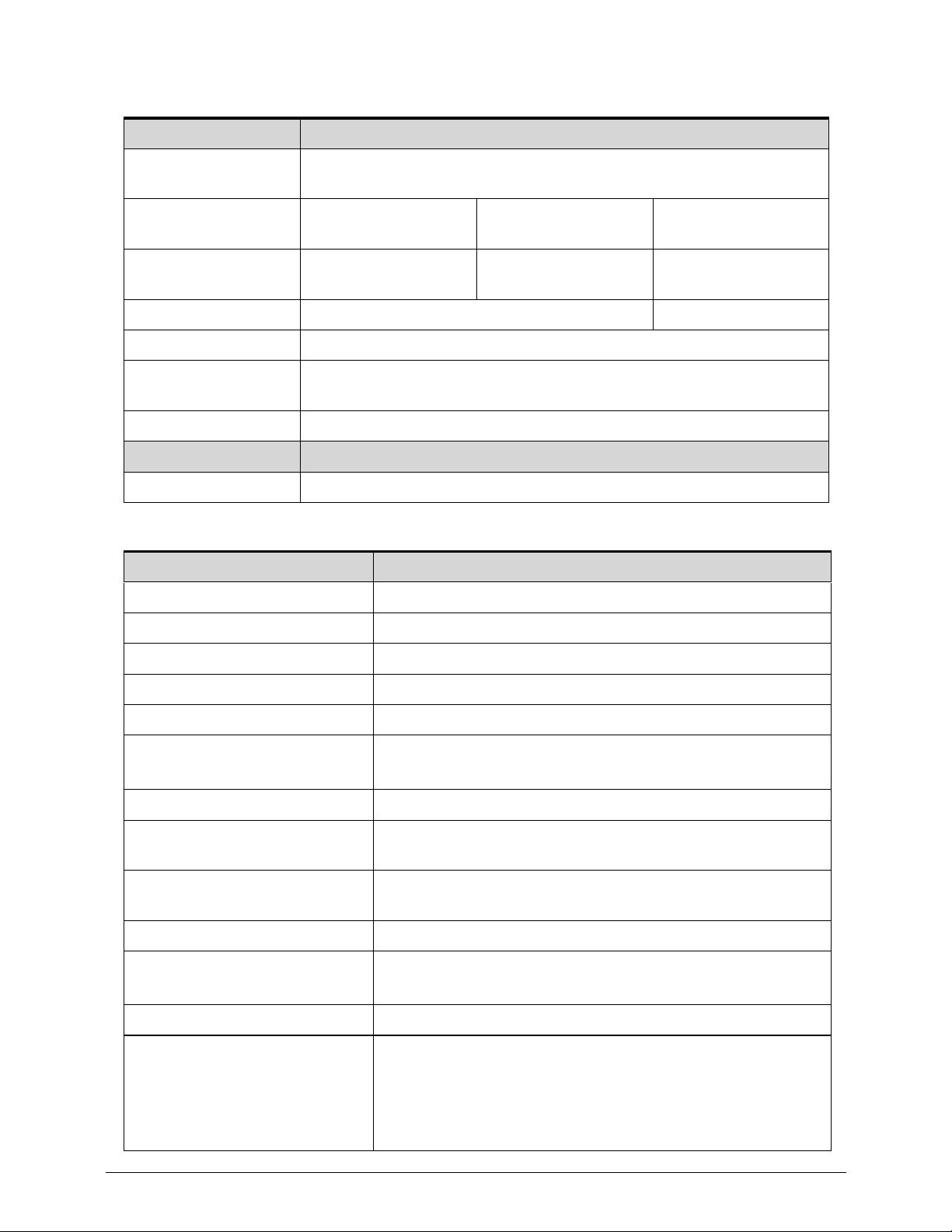
Blu-Ray Drive (N/A)
LED 14”
Items Specifications
Vendor & Model
name
Performance
Specification
Transfer rate
(KB/sec)
Buffer Memory
Interface
Applicable disc
format
Loading mechanism
Power Requirement
Input Voltage
Item Specification
Vendor/Model name AUO B156XW02 V3
Screen Diagonal (mm) 394.91
Active Area (mm) 344.23 x 193.54
Display resolution (pixels) 1366(H) x 768(V)
Pixel Pitch (mm) 0.2588 x0.2588
Typical White Lumina nce
(cd/m
2
) also called Brightness
200 typ. (5 points average)
170 min. (5 points average)
Contrast Ratio 400 typ
Response Time (Optical Rise
Time/Fall Time) msec
8 typ / 16 Max
Typical Power Consumption
(watt)
5.6 max. (Include Logic and Blu power)
Weight (without inverter) 450 max.
Physical Size (mm) 359.3 x 209.5 (typical)
360 x 210 x 5.5 (max)
Electrical Interface 1 channel LVDS
Viewing Angle (degree)
Horizontal (Right) CR = 10
(Left)
Vertical (Upper) CR = 10
(Lower)
45 / 45 / 15 / 35 (typical)
40 / 40 / 10 / 30 (min)
Page 40
1-30 Hardware Specifications and Configurations
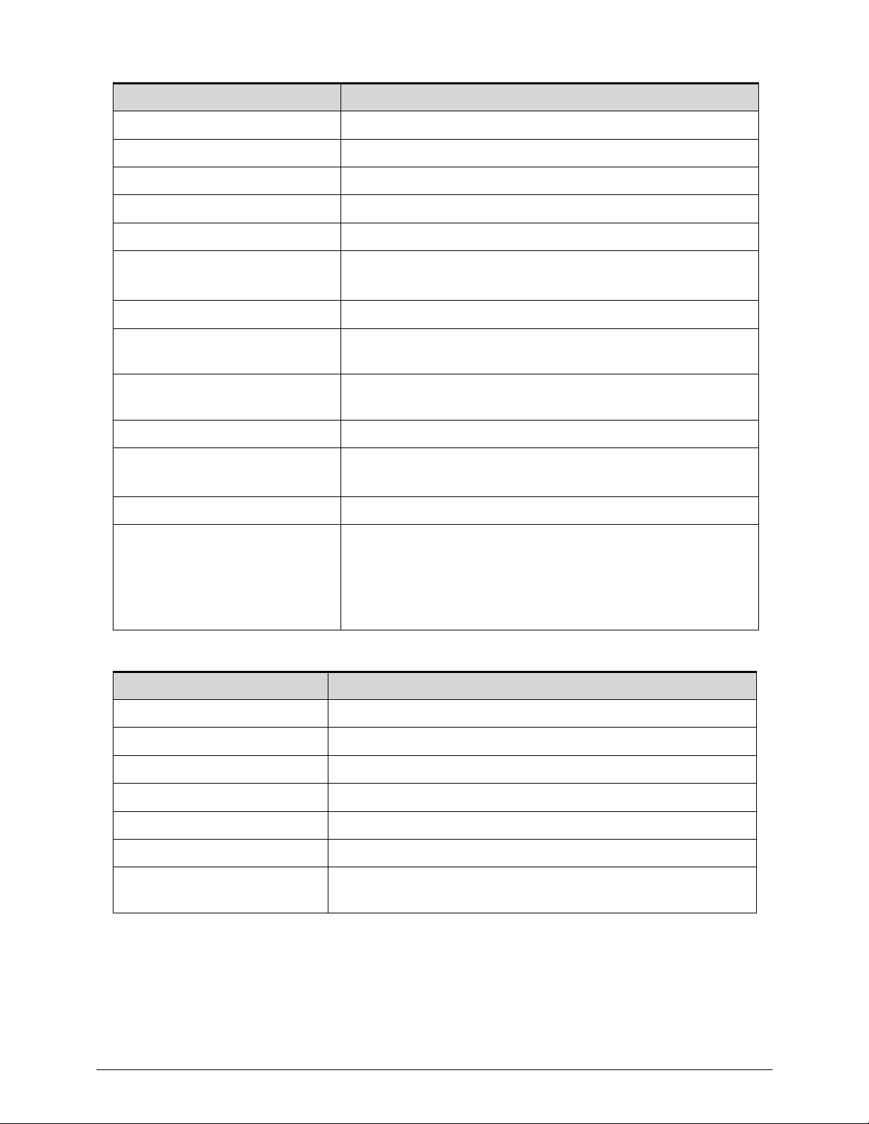
LCD Inverter (N/A)
Vendor/Model name AUO B156XW02 V6
Screen Diagonal (mm) 394.91
Active Area (mm) 344.23 x 193.54
Display resolution (pixels) 1366 x 3(RGB) x 768
Pixel Pitch (mm) 0.252 x 0.252
Typical White Lumina nce
(cd/m
2
) also called Brightness
200 typ. (5 points average)
170 min. (5 points average)
Contrast Ratio 500 typ
Response Time (Optical Rise
Time/Fall Time) msec
16 Max
Typical Power Consumption
(watt)
4.5 max. (Include Logic and Blu power)
Weight (without inverter) 450 max.
Physical Size (mm) 359.3 x 209.5 (typical)
360 x 210 x 5.5 (max)
Electrical Interface 1 channel LVDS
Viewing Angle (degree)
Horizontal (Right) CR = 10
(Left)
Vertical (Upper) CR = 10
(Lower)
45 / 45 / 15 / 35 (typical)
40 / 40 / 10 / 30 (min)
Item Specification
Vendor & Model name
Brightness conditions
Input voltage (v)
Input current (mA)
Output voltage (V, RMS)
Output current (mA, RMS)
Output voltage frequency
(KHz)
Item Specification
Page 41
Hardware Specifications and Configurations 1-31
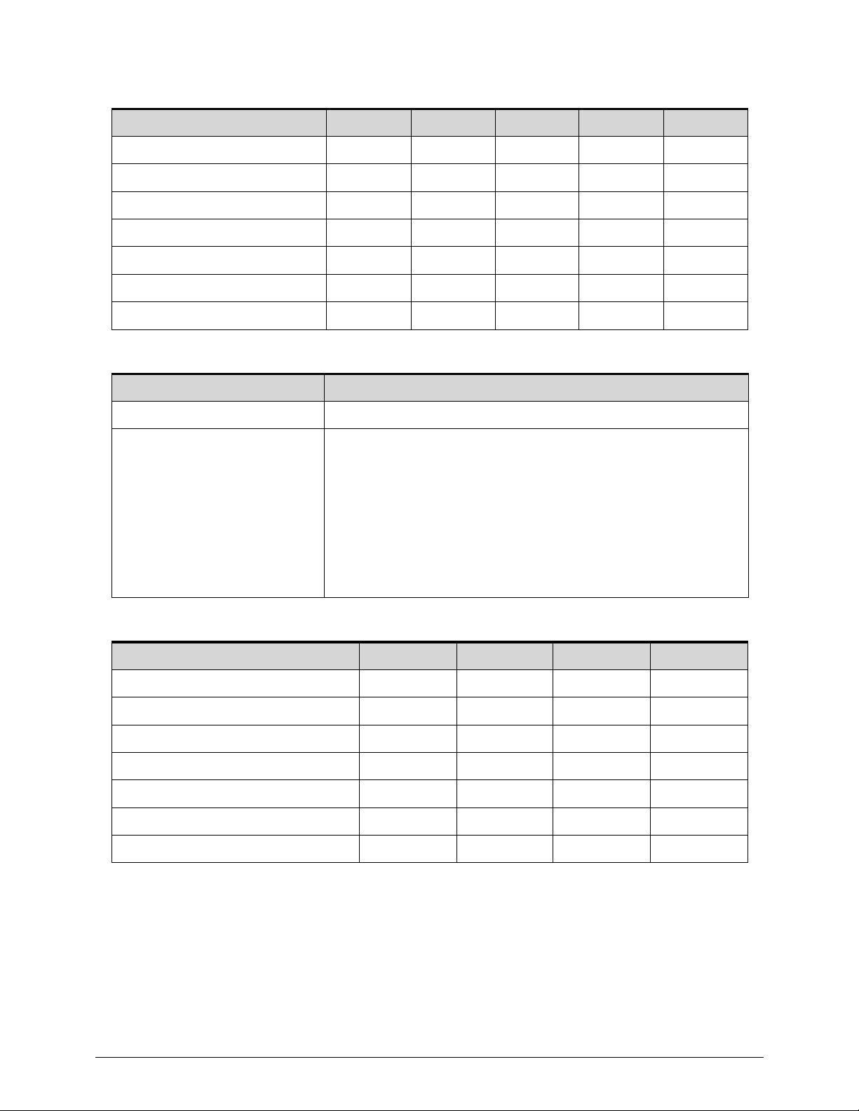
Display Supported Resolution (LCD)
Graphics Controller (GPU not Interface)
Display Supported Resolution (GPU)
Resolution 8 bits 16 bits 32 bits 36 bits 48 bits
800x600p/60Hz 16:9 Y Y Y Y Y
1024x768p/60Hz 16:9 Y Y Y Y Y
1280x600/60Hz 16:9 Y Y Y Y Y
1280x720/60Hz 16:9 Y Y Y Y Y
1280x768/60Hz 16:9 Y Y Y Y Y
1360x768/60Hz 16:9 Y Y Y Y Y
1366x768/60Hz 16:9 Y Y Y Y Y
Item Specification
VGA Chip NvidiaNGeForce GT 640M (O ptimus)
Supports Advanced Scheduler 2.0, 1.0, XPDM support
DX10.1, DX10, DX9 support
OGL 3.0 support
Support CRT/LVDS/HDMI/DP interface (concurrent)
Dual-channel LVDS interface support: single channel 24 bpp
dual link
Direct X 11 and Shader Model 5.0
OpenGL 3.2 support
Resolution 8 bits 16 bits 32 bits 48 bits
800x600p/60Hz 16:9 Y Y Y N/A
1024x768p/60Hz 16:9 Y Y Y Y
1280x600/60Hz 16:9 Y Y Y Y
1280x720/60Hz 16:9 Y Y Y Y
1280x768/60Hz 16:9 Y Y Y Y
1360x768/60Hz 16:9 Y Y Y Y
1366x768/60Hz 16:9 Y Y Y Y
Page 42
1-32 Hardware Specifications and Configurations
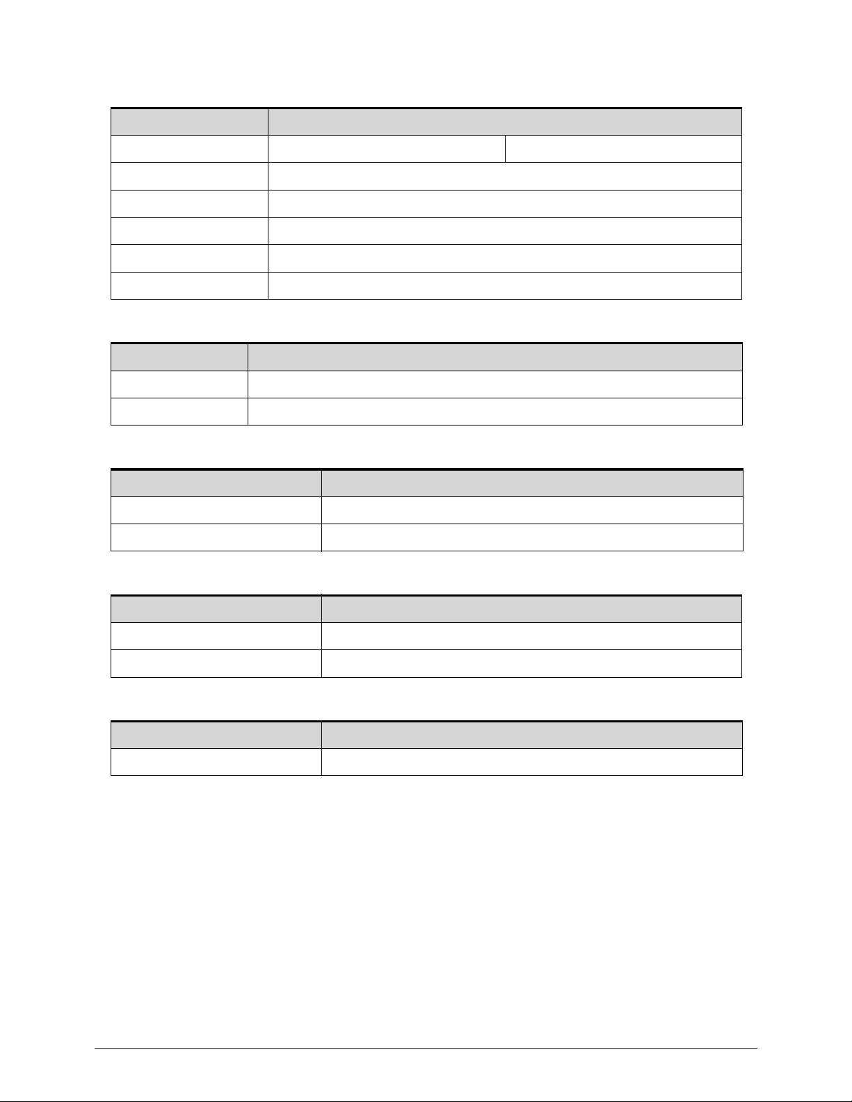
Bluetooth Interface (Optional)
Bluetooth Module (Optional)
Camera
3G Card (N/A)
Audio Codec and Amplifier
Item Specifications
Chipset
Data throughput
Protocol
Interface
Connector type
Supported protocol
Item Specifications
Item Specification
Vendor and Model Liteon 1.3M 10P2SF205, Suyin 1.3M HD HF1316
Type 1.3M
Item Specification
Item Specification
Audio Controller Conexant CX20584-21Z
Page 43

Hardware Specifications and Configurations 1-33
Features 24-bit, 2 pairs of independent DACs and 3 pairs of
independent ADCs
ProCoustic headphone driver delivers 50 mW into 32 _ load
with no pop, eliminating the need for an external amplifier
and DC-blocking capacitors
Integrated 5 V to 3.3 V low-dropout voltage regulator for
improved audio performance, eliminating need for external
regulator or power transistor.
Integrated 3.3 V to 1.8 V low-dropout voltage regulator, used
to power digital blocks
Integrated 2 WRMS (per channel) class-D stereo speaker
amplifier with Spread
Spectrum and 10-kV ESD withstand capability
Digital Microphone interface with internal MIC boost
supporting 2 digital microphone elements
Works with all digital microphones.
Internal microphone boost
Digital: 0, 12, 24, 36, 48 dB
Analog: 0, 10, 20, 30, 40 dB
Microphone Security Control
Please contact Conexant Sales/FAE for additional
confidential document to disable the bit in mi crophone from
the BIOS.
Exceeds Windows Vista and Windows 7 Desktop and
Notebook Premium Logo Requirements, WLP4.0
D-Flex power management exceeds Intel ECR 15B
requirements, and features
Wake-On-PCBeep functionality
Hardware Headphone limiter bit (supports GS Mark
EN50332-2)
Compliant with Intel High Definition Audio Specification Rev.
1.0
Supports both 1.5 V and 3.3 V signaling with the core logic
chipset
Retaskable ports
Configure between Headphone and Line-out or between
Mic and Line-in
Independent sampling rate for DAC and ADC; supports au dio
formats ranging
from 16-bit, 44.1 kHz to 24-bit, 192 kHz for DACs, and from
16-bit, 44.1 kHz to 24-bit,96 kHz for ADCs.
Item Specification
Page 44

1-34 Hardware Specifications and Configurations
Features Independent sampling rate for DAC and ADC; supports au dio
formats ranging
from 16-bit, 44.1 kHz to 24-bit, 192 kHz for DACs, and from
16-bit, 44.1 kHz to 24-bit,96 kHz for ADCs.
Pop Shield: pops and clicks reduction circuitry, including
class-D speaker outputs
Jack sense detects up to 8 jacks using only two sense pins
Dual Sony Philips Digital Interface (S/PDIF) outputs
Digital Mixer
Simultaneous DAC and SPDIF engines
+3.3 V analog and I/O operation; uses Vaux for power
management modes
SmartAudio GUI (optional) - advanced audio control
Digital Parametric SmartEQ with Dynamic Range
Compression (DRC)
Enhances the sound quality on low cost speakers
Night Mode
3D Expander
Third-party Logo software support
Andrea
Creative Labs
Dolby
®
Fortemedia
MaxxAudio
Sonic FocusTM
SRS
®
Supports 32-bit/64-bit Windows OS and Linux
48-QFN packages
Amplifier N/A
Item Specification
Page 45
Hardware Specifications and Configurations 1-35
Audio Interface
Wireless Module 802.11b/g/n
Battery
VRAM
Item Specification
Audio Controller Realtek ALC271-VB
Audio onboard or optional On board
Mono or Stereo Stereo
Compatibility HD audio Interface
Sampling rate Sample rate up to 192Khz resolution VSR (Variable Sampling
Rate)
Internal microphone Yes
Internal speaker/quantity Yes/(2W speakers x2)
Item Specification
Chipset Atheros WB222
Data throughput 11-54 Mbps, up to 300 Mbps for Draft-N
Protocol b, g, n
Interface PCI-E
Item Specification
Vendor & Model
name
SANYO AP12A3i
Battery Type Li-Ion
Pack capacity 4850mAh
Number of battery cell 3
Package
configuration
2S1P
Item Specification
Chipset Elpida Hynix
Memory size 4Gb 4Gb
Interface Standard define Standard define
Page 46
1-36 Hardware Specifications and Configurations
USB Port
HDMI Port
AC Adapter
Item Specification
USB compliance level USB 3.0
EHCI 2
Number of USB port(s) 2
Location 2 on rear side
Output Current 0.5A, 0.75A(ACER SPEC)
Item Specification
Compliance level HDMI1.4a
Data throughput Up to 16.7 million colors
Number of HDMI port(s) 1
Location 1 left side
Item Specification
Input rating 100-240V~1.7A(1,7A) 50-60Hz
Maximum input AC current 1.7A(1,7A) 50-60Hz
Maximum input AC current 264 Vrms
Inrush current 264 Vac (Cold/Hot start) No damage; meet fuse and bridge
diode I2t de-rating.
Efficiency Meets EPA 2.0 level V requirement. The adapter efficiency
shall be more than 87%, that is the average value of 25%,
50%, 75% and 100% load with both 115Vac/60Hz and
230Vac/50Hz input voltage condition
Page 47
Hardware Specifications and Configurations 1-37
System Power Management
Item Specification
Mech. Off (G3) Al devices in the system are turned off completely.
Soft Off (G2/S5) OS initiated shutdown. All devices in the system are turned of f
completely.
Working (G0/S0) Individual devices such as the CPU and hard disc may be
power managed in this state.
Suspend to RAM (S3)
CPU set power down
VGA Suspend
Audio Power Down
Hard Disk Power Down
CD-ROM Power Down
Super I/O Low Power mode
Save to Disk (S4) Also called Hibernation Mode. System saves all system states
and data onto the disc prior to power off the whole system.
Page 48

1-38 Hardware Specifications and Configurations
Card Reader
Item Specification
Chipset Realtek RTS5209
Package 48-PIN LQFP
Maximum supported size 32G
Features
Compliant with PCI Express Base Specification Revision 1.1
Support 1-Lane 2.5Gbps PCI Express Bus
Support 93C46 EEPROM
Compliant with SD Part 1 Physical Layer Specification
Versio n 3.01
Compliant with SDIO Specification Version 2.00
Compliant with MultiMediaCard System Specification version
4.4
Compliant with Memory Stick XC Duo Format Specification
Version 1.00-00
Compliant with Memory Stick XC-HG Duo Format
Specification Version 1.00-00
Compliant with Memory Stick XC Micro Format Specification
Version 1.00-00
Compliant with Memory Stick XC-HG Micro Format
Specification Version 1.00-00
Compliant with Memory Stick PRO-HG Duo Format
Specification Version 1.03-00
Compliant with Memory Stick HG Micro Format Specification
Version 1.00-00
Compliant with Memory Stick PRO Standard Format
Specification Version 1.05-00
Compliant with Memory Stick Standard Format Specification
Versio n 1.43
Compliant with xD-Picture Card Specifications Version 1.2
Support the following memory card interfaces:
Secure Digital TM (SD), SDXC, SDHC, MultiMediaCard
TM (MMC), Mini-SD, Micro-SD (T-flash),
Page 49
Hardware Specifications and Configurations 1-39
System LED Indicator
System DMA Specification
System Interrupt Specification
Item Specification
Lock
Caps Lock on = Blue
Caps Lock on = Blue
System state
Blue color on: System on
Blue color and amber color off: System off
Amber color on: S3
HDD access state HDD access active = Blue
Wireless state Wifi on = Amber
Power button backlight
Blue color solid on: System on
Blue color off: System off
Battery state
Full charging = Blue
Battery charging = Amber
Legacy Mode Power Management
DMA4 Direct memory access controller
Hardware IRQ System Function
IRQ0 System timer
IRQ1 Standard PS/2 Keyboard
IRQ8 System CMOS/real time clock
IRQ12 ELAN Ps/2 Port Smart-Pad
IRQ13 Numberic data processor
IRQ81 ~ IRQ190 Microsoft ACPI-Compliant
PCI10 Intel(R) 7 Series /C216 Chipset Family SMBus Host Controller -
1E22
PCI16 Intel(R) 7 Series/C216 Chipset Family USB Enhanced Host
Controller - 1E2D
PCI16 Intel(R) 7 Series/C216 chipset family PCI Express Root Port 2 -
1E12
PCI16 Intel(R) 7 Mangement Engine Interface
PCI16 NVIDIA GeForce GT 640M LE
PCI16 Xeon(R) processor E3-1200 v2/3rd Gen Core processor PCI
Express Root Port -0151
PCI17 Intel(R) 7 Series/C216 Chipset Family PCI Express Root Port 1
- 1E10
Page 50
1-40 Hardware Specifications and Configurations
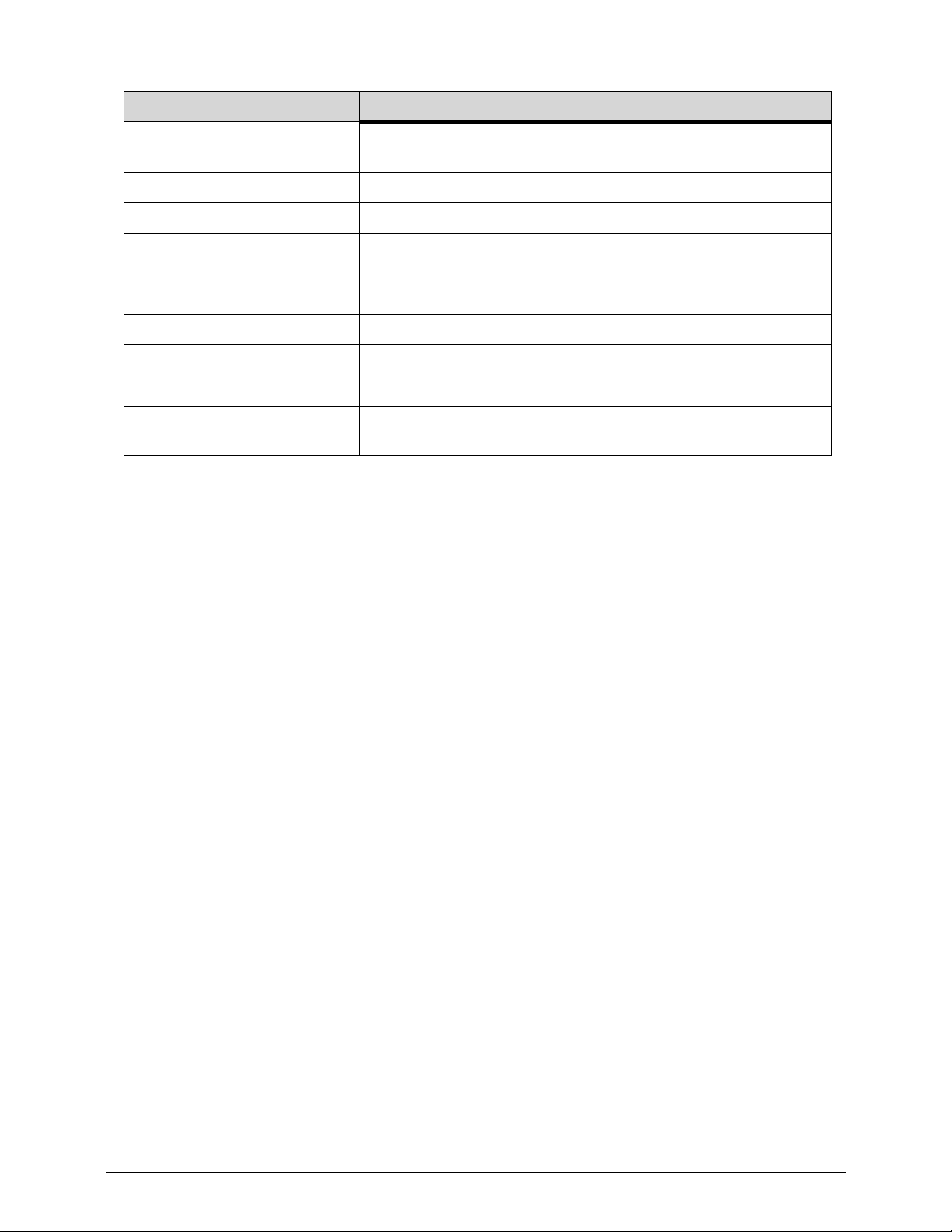
PCI18 Intel(R) 7 Series/C216 Chipset Family PCI Express Root Port
3- 1E10
PCI19 Intel(R) 7 Series chipest family SATA AHCI Controller
PCI19 Qualcomm Atheros AR5BWB222 Wireless Network Adapter
PCI22 High Definition Audio Controller
PCI23 Intel(R) 7 Series/c216 chipset family sub enhanced Host
Controller -1E26
PCI-5 Broadcom Netlink (TM) Gigabit Ethernet
PCI-4 Intel(R) 7 USB 3.0 eXtensible Host Controller
PCI-3 Intel(R) 7 HD Gaphics 4000
PCI-2 Intel(R) 7 series/c216 chipset family pci Express Root Port 8 -
1E1E
Hardware IRQ System Function
Page 51
Hardware Specifications and Configurations 1-41
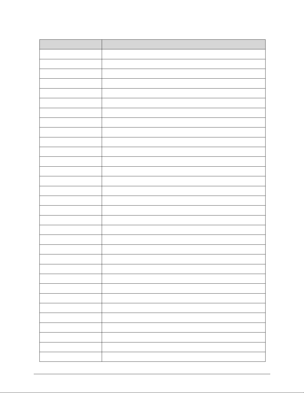
System IO Address Map
I/O address (hex) System Function (shipping configuration)
000 - 01F Direct memory access controller
020 - 021 Programmable interrupt controller
024 - 025 Programmable interrupt controller
028 - 029 Programmable interrupt controller
02C - 02D Programmable interrupt controller
02E - 02F Motherboard resources
030 - 031 Programmable interrupt controller
034 - 035 Programmable interrupt controller
038 - 039 Programmable interrupt controller
03C - 03D Programmable interrupt controller
040 - 043 System timer
04E - 04F Motherboard resources
050 - 053 System timer
60 Standard PS/2 Keyboard
61 Motherboard resources
62 Microsoft ACPI-Compliant Embedded Controller
63 Motherboard resources
64 Standard PS/2 Keyboard
65 Motherboard resources
66 Microsoft ACPI-Compliant Embedded Controller
67 Motherboard resources
07 Motherboard resources
070 - 077 System CMOS/real time clock
80 Motherboard resources
081 - 091 Direct memory access controller
92 Motherboard resources
093 - 09F Direct memory access controller
0A0 - 0A1 Programmable interrupt controller
0A4 - 0A5 Programmable interrupt controller
0A8 - 0A9 Programmable interrupt controller
0AC - 0AD Programmable interrupt controller
0B0 - 0B1 Programmable interrupt controller
Page 52
1-42 Hardware Specifications and Configurations
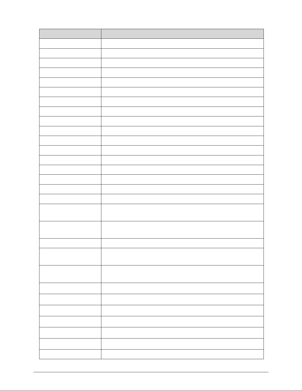
0B2 - 0B3 Motherboard resources
0B4 - 0B5 Programmable interrupt controller
0B8 - 0B9 Programmable interrupt controller
0BC - 0BD Programmable interrupt controller
0C0 - 0DF Direct memory access controller
0F0 Numeric data processor
3B0 - 3BB Inter(R)HD Graphics Family
3C0 - 3DF Inter(R)HD Graphics Family
400-453 Motherboard resources
454 - 457 Motherboard resources
458 - 47F Motherboard resources
4D0 - 4D1 Programmable interrupt controller
500 - 57F Motherboard resources
680 - 69F Motherboard resources
D00-FFFF PCI BUS
1100-110F Motherboard resources
164E-164F Motherboard resources
2000-2FFF
Inte
®
6 Series/C200 Series Chipset Family PCI Express Root Port
6-1C1A
3000-3FFF
Intel
®
6 Series/C200 Series Chipset Family PCI Express Root Port
5-1C18
3F80-3FFF NVIDIA GeForce GT 640M LE
4000-4FFF
Intel
®
6 Series/C200 Series Chipset Family PCI Express Root Port
2-1C12
5000-5FFF
2
nd
generation Intel® Core™ processor family PCI Express
Controller - 0101
6000-603F
Intel
®
HD Graphics Family
6060-607F
Intel
®
6 Series/C200 Series Chipset Family SMBus Controller - 1C22
6080-6087
Intel
®
Mobile Express Chipset SATA AHCI Controller
6088-608F
Intel
®
Mobile Express Chipset SATA AHCI Controller
6098-609B
Intel
®
Mobile Express Chipset SATA AHCI Controller
609C-609F
Intel
®
Mobile Express Chipset SATA AHCI Controller
FFFF Motherboard resources
I/O address (hex) System Function (shipping configuration)
Page 53
Hardware Specifications and Configurations 1-43
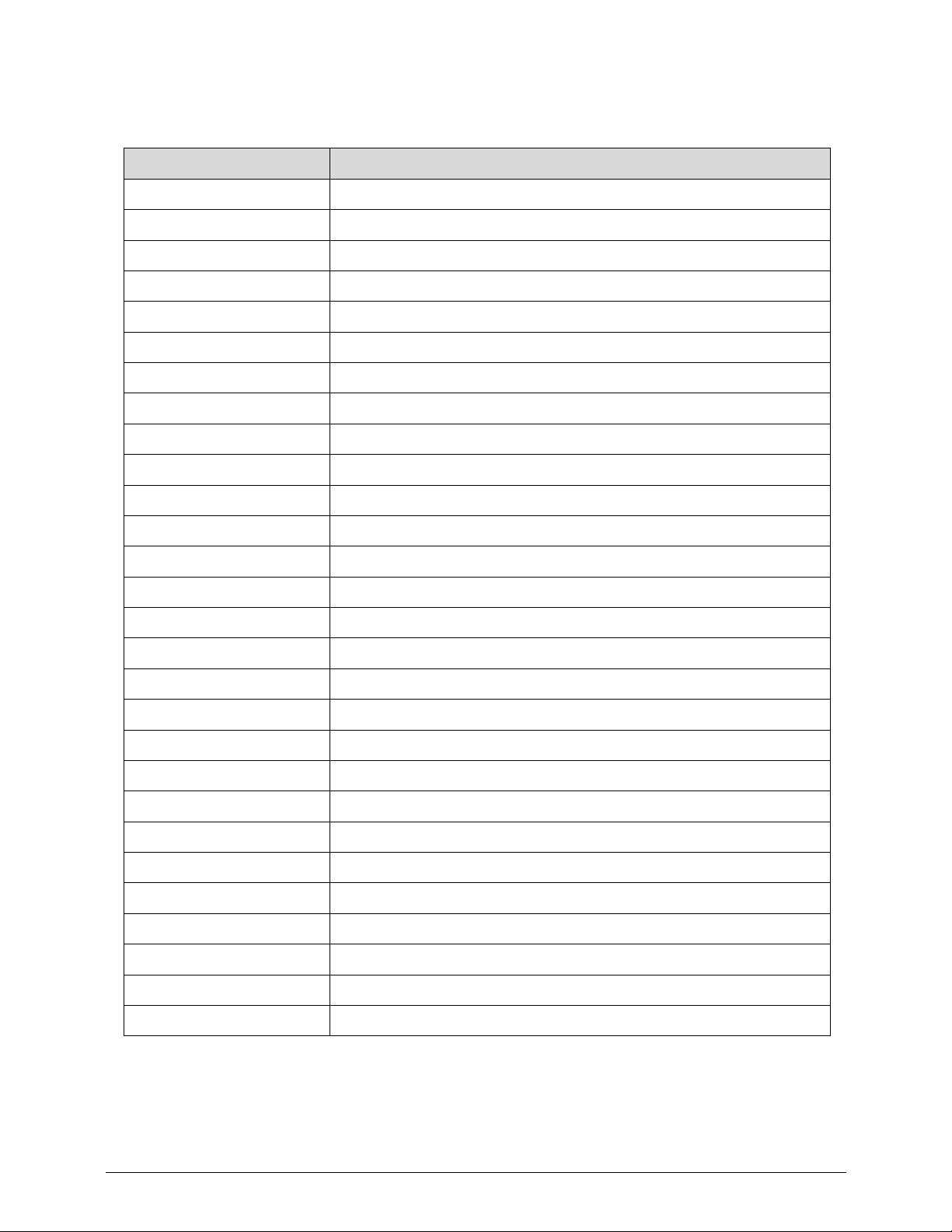
System I/O Address Specifications
(Not available for this model)
I/O address (hex) System Function (shipping configuration)
220 - 22F
230 - 26D
26E - 26
278 - 27F
280 - 2AB
2A0 - 2A7
2A8 - 2E7
2E8 - 2EF
2F0 - 2F7
2F8 - 2FF
300 - 31F
320 - 36F
370 - 377
378 - 37F
380 - 387
388 - 38B
38C - 3AF
3B0 - 3BB
3BC - 3BF
3C0 - 3DF
3E0 - 3E1
3E2 - 3E3
3E8 - 3EF
3F0 - 3F7
3F8 - 3FF
CF8 - CFB
(PCIDIVO-1)
(PCIDIVO-1)
Page 54

1-44 Hardware Specifications and Configurations
Page 55

CHAPTER 2
System Utilities
Page 56

2-2
Page 57

Acer M5 481/481G/481T/481TG System Utilities 2-3
Acer M5 481/481G/481T/481TG System Utilities
BIOS Setup Utility 0
This utility is a hardware configuration program built into a computer’s BIOS (Basic
Input/Output System).
The utility is pre-configured and optimized so most users do not need to run it. If configuration
problems occur, the setup utility may need to be run. Refer to Troubleshooting when a problem
arises.
To activate the utility, press
F2 during POST (power-on self-tes t) when prompted at th e bottom
of screen.
The default parameter of F12 Boot Menu is set to Disabled. To change the boot device
without entering BIOS Setup Utility, set the parameter to Enabled.
To change the boot device without entering the BIOS SETUP, press F12 during POST to enter
the multi-boot menu.
Navigating the BIOS Utility 0
Six menu options are:
Information
Main
Security
Boot
Exit
To navigate through the following:
Menu - use the left and right arrow keys
Item - use the up and down arrow keys
Change parameter value - press F5 or F6.
Exit - Press Esc
Load default settings - press F9. Press F10 to save changes and exit BIOS Setup
Utility
NOTE:
NOTE:
Parameter values can be changed if enclosed in square brackets [ ]. Navigation keys
appear at the bottom of the screen. Read parameter help carefully when making
changes to parameter values. Parameter help is found in th e Item Specific Help area of
the screen.
NOTE:
NOTE:
System information is subject to specific mode ls.
Page 58
2-4 Acer M5 481/481G/481T/481TG System Utilities
BIOS 0
The following is a description of the tabs found on the InsydeH20 BIOS Setup Utility screen:
NOTE:
NOTE:
The screens provided are for reference only. Actual values may differ by model.
Information 0
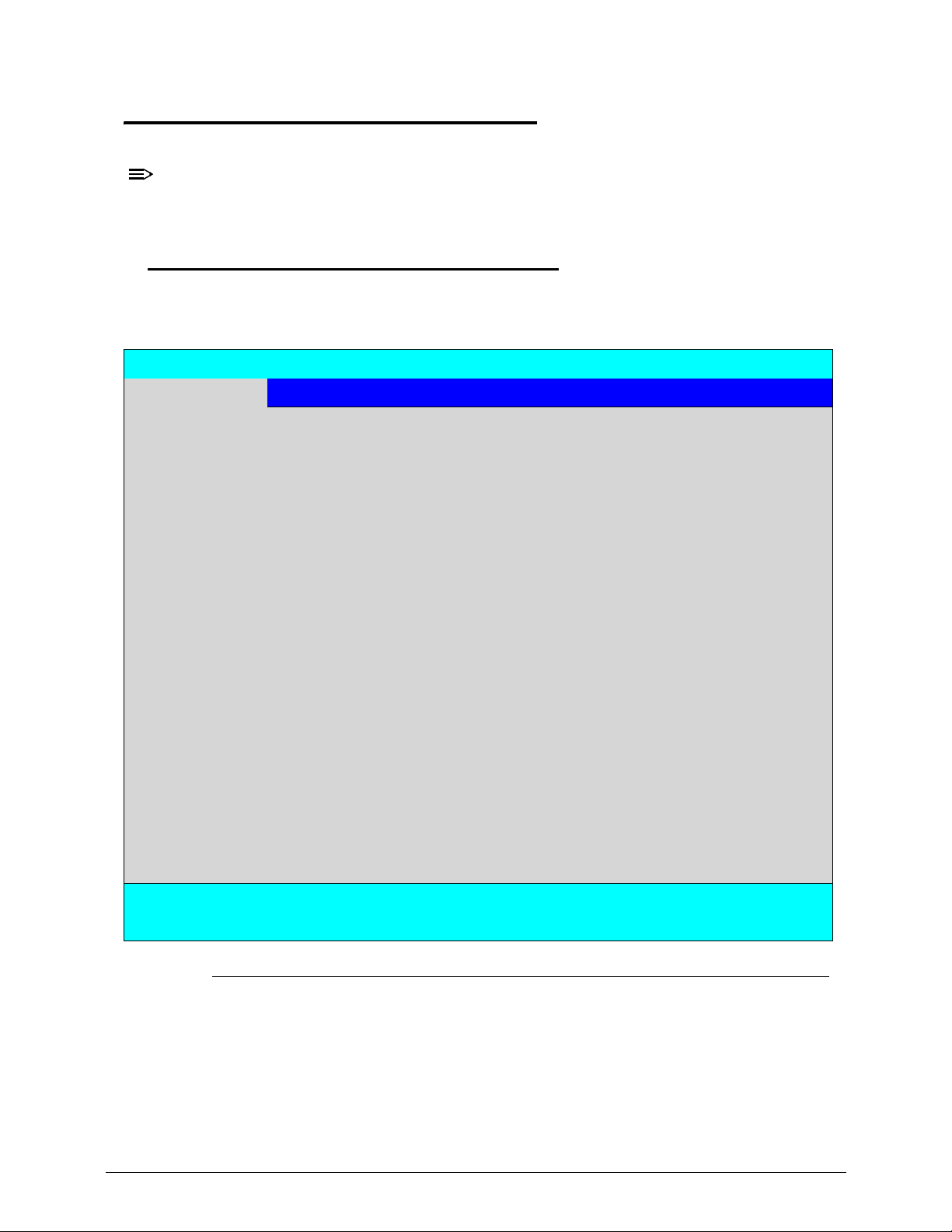
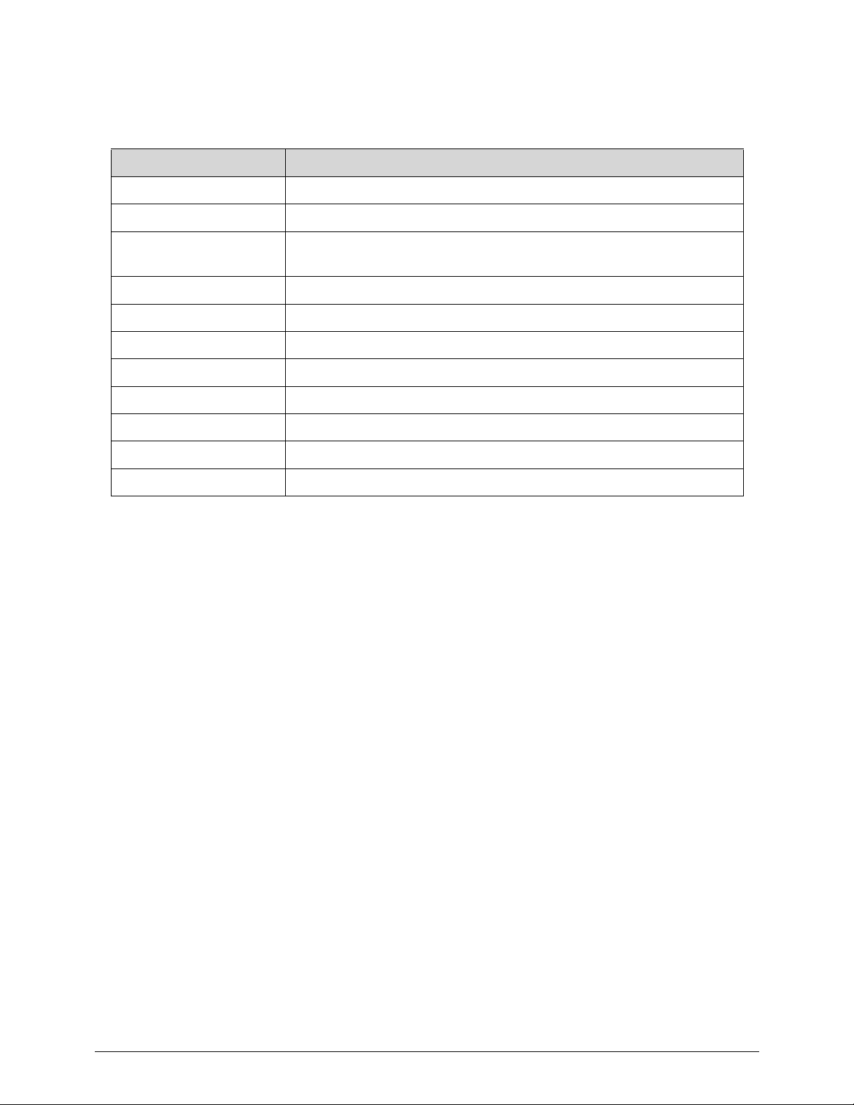
Table 2-1 describes the parameters shown in Figure 2-1.
Figure 2-1. BIOS Information
InsydeH20 Setup Utility Rev. 3.7
Information Main Security Boot Exit
CPU Type: Intel(R) Core(TM) i7-3517U CPU @ 1.90GHz
CPU Speed: 1.90GHz
HDD Model Name:
HDD Serial Number:
ATAPI Model Name:
System BIOS Version: V1.02
VGA BIOS Version: nVidia VGA REV80.07.23.00.11
Serial Number: xxxxxxxxxxxxxxxxxxxx
Asset Tag Number: xxxxxxxxxxxxxxxxxx
Product Name: xxxxxxxxxxxxxxxx
Manufacturer Name: xxxxxxxxxxxxxxxxxxxx
UUID: xxxxxxxxxxxxxxxxxxxx
F1 Help Select Item F5/F6 Change Values F9 Setup Default
ESC Exit Select Menu Enter Select>SubMenu F10 Save and Exit
Page 59
Acer M5 481/481G/481T/481TG System Utilities 2-5
Table 2-1 describes the parameters shown in Figure 2-1.
Table 2-1. BIOS Information
Parameter Description
CPU Type CPU (central processing unit) type and speed of system
CPU Speed Speed of the CPU
HDD0 Model Name Model name of HDD0 (hard disk drive) installed on primary IDE
master
HDD0 Serial Number Serial number of HDD0 installed on primary IDE master
ATAPI Model Name Model name of Optical device installed in system
System BIOS Version System BIOS version
VGA BIOS Version VGA (video graphics array) firmware version of system
Serial Number Serial number of unit
Asset Tag Number Asset tag number of system
Product Name Product name of the system
UUID Universally Unique Identifier
Page 60
2-6 Acer M5 481/481G/481T/481TG System Utilities
Main 0
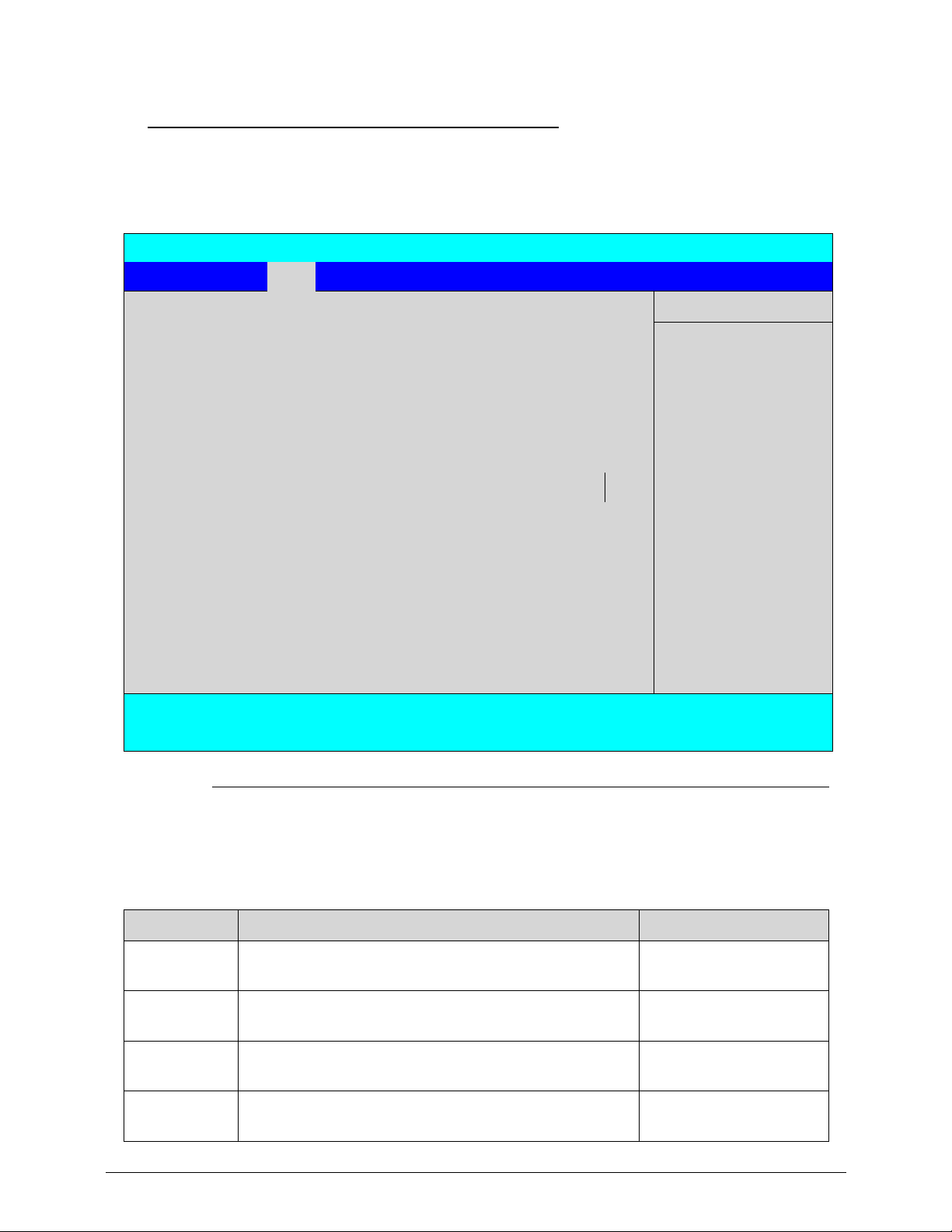
The Main tab allows the user to set system time and date, enable or disable boot option and
enable or disable recovery.
Figure 2-2. BIOS Main
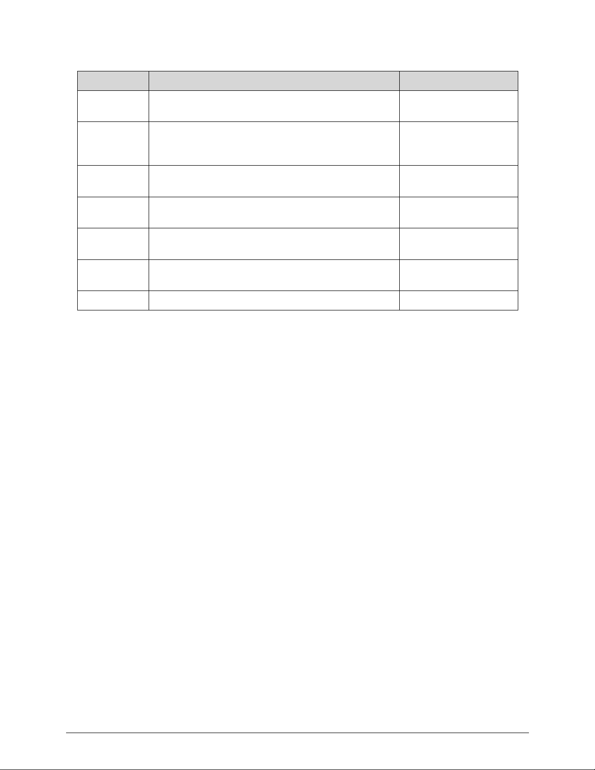
Table 2-2 describes the parameters shown in Figure 2-2.
.
InsydeH20 Setup Utility Rev. 3.7
Information Main Security Boot Exit
Item Specific Help
System Time [09:00:00] <Tab>, <Shift-Tab>, or
<Enter> selects field
System Date [01/01/2012]
Total Memory: xxxx MB
Video Memory: [xMB]
Graphic Mode [Switchable]
Quiet Boot [Enabled]
Network Boot [Enabled]
F12 Boot Menu [Disabled]
D2D Recovery [Enabled]
Wake on LAN [Disabled]
SATA Mode [AHCI Mode]
F1 Help Select Item F5/F6 Change Values F9 Setup Default
ESC Exit Select Menu Enter Select>SubMenu F10 Save and Exit
Table 2-2. BIOS Main
Parameter Description Format/Option
System Time BIOS system time in 24-hour format Format: HH:MM:SS
(hour:minute:second)
System Date BIOS system date Format MM/DD/YYYY
(month/day/year)
Total
Memory
Total memory available N/A
Video
Memory
Available memory for video N/A
Page 61
Acer M5 481/481G/481T/481TG System Utilities 2-7
Graphic
Mode
Option for Integrated or Switchable graphic mode. Option: Integrated or
Switchable
Quiet Boot Shows OEM (original equipment manufacturer)
screen during system boot instead of traditional
POST screen
Option: Enabled or
Disabled
Network
Boot
Option to boot system from LAN (local area network) Option: Enabled or
Disabled
F12 Boot
Menu
Option to use boot menu during POST Option: Enabled or
Disabled
D2D
Recovery
Option to use D2D Recovery function Option: Enabled or
Disabled
Wake on
LAN
Option to wake up system through LAN (local area
network)
Option: Enabled or
Disabled
SATA Mode Option to set SATA controller mode Option: AHCI or IDE
Table 2-2. BIOS Main (Continued)
Parameter Description Format/Option
Page 62
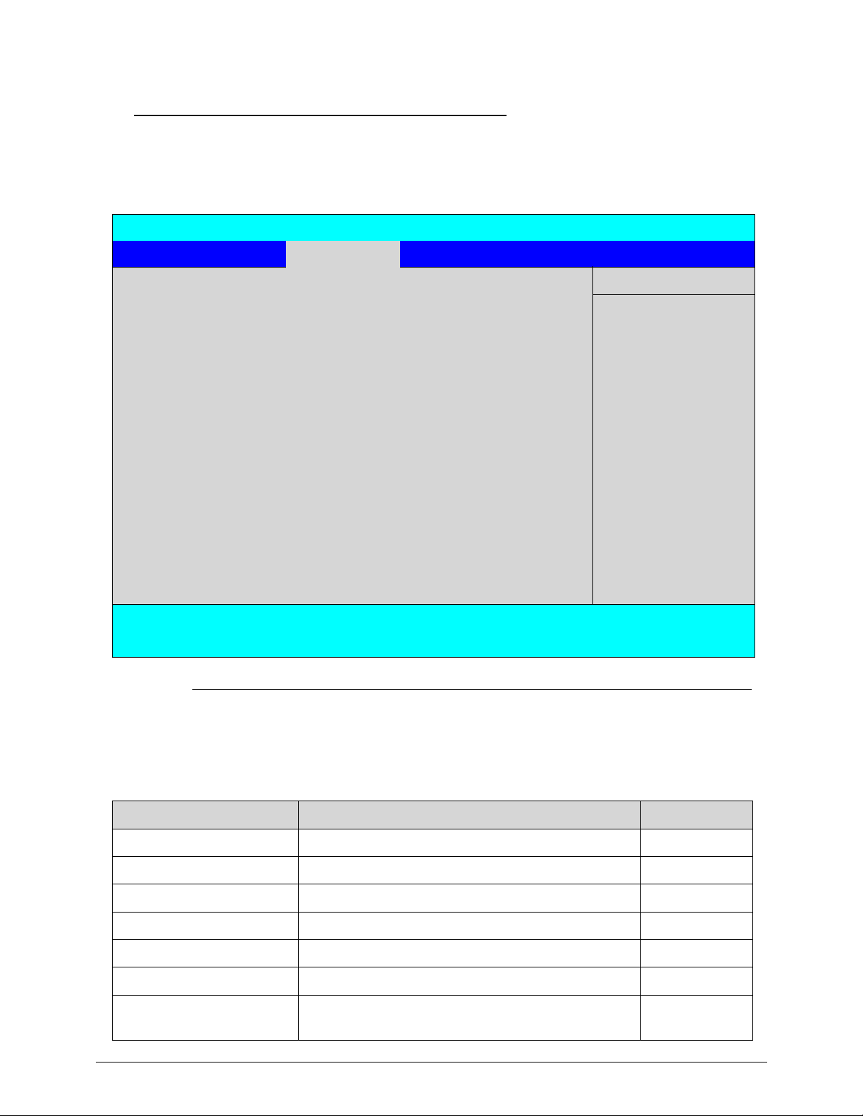
2-8 Acer M5 481/481G/481T/481TG System Utilities
Security 0
The Security tab shows parameters that safeguard and protect the computer from
unauthorized use.
Figure 2-3. BIOS Security
Table 2-3 describes the parameters shown in Figure 2-3.
InsydeH20 Setup Utility Rev. 3.5
Information Main Security Boot Exit
Item Specific Help
Supervisor Password Is:
Clear
Supervisor Password
controls access to the
whole setup utility. It
can be used to boot up
when Password on
boot is enabled.
User Password Is:
Clear
HDD Password Is:
Frozen
Set Supervisor Password [Enter]
Set User Password [Enter]
Set HDD Password [Enter]
Password on Boot [Disabled]
F1 Help Select Item F5/F6 Change Values F9 Setup Default
ESC Exit Select Menu Enter Select>SubMenu F10 Save and Exit
Table 2-3. BIOS Security
Parameter Description Option
Supervisor Password Is Supervisor password setting
Clear or Set
User Password Is User password setting
Clear or Set
HDD0 Password Is HDD0 password setting
Clear or Set
Set Supervisor Password Option to set supervisor password
N/A
Set User Password Option to set user password N/A
Set HDD Password Option to set HDD0 password N/A
Password on Boot Shows if password is required during system boot Disabled or
Enabled
Page 63
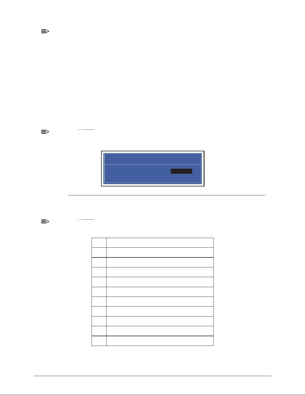
Acer M5 481/481G/481T/481TG System Utilities 2-9
NOTE:
NOTE:
When prompted to enter password, three attempts are allowed before system halts.
Resetting BIOS password may require computer be returned to dealer.
Password on Boot must be set to Enabled to activate password feature.
Passwords are not case sensitive.
A password must be alphanumeric (A-Z, a-z, 0-9), not longer than 12 characters.
Setting a Password 0
Perform the following to set a new user or supervisor password:
1. Use the and keys to highlight the Set Supervisor Password parameter and press
Enter. The Set Supervisor Password dialog box is shown. (Figure 2-4)
NOTE:
NOTE:
To change an existing password, refer to Changing a Password.
Figure 2-4. Setting a Password: Set Supervisor Password
2. Type a new password in the Enter New Password field and press Enter.
NOTE:
NOTE:
The following characters may be used in a password:
IMPORTANT:
+
Use care when typing a password. Characters do not appear on the screen.
A-Z Alphabets A through Z (Not Case Sensitive)
0-9 Numerical Characters.
-Dash
= Equal Sign
[ Left Bracket
] Right Bracket
.Period
, Comma
; Semi-colon
/Slash
\ Back-slash
Set Supervisor Password
Enter New Password [ ]Enter New Password
Confirm New Password [ ]
Page 64
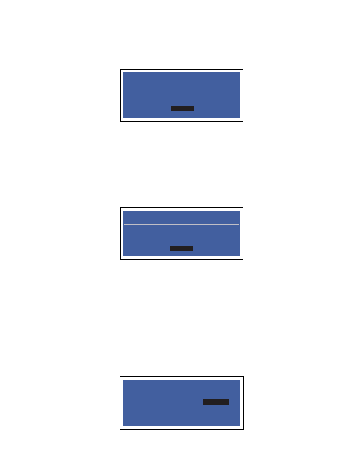
2-10 Acer M5 481/481G/481T/481TG System Utilities
3. Retype password in the Confirm New Password field and press Enter.
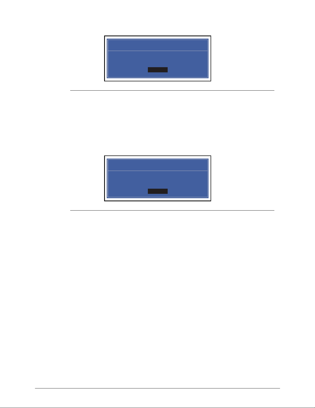
4. If new password and confirm new password strings match, the Setup Notice dialog
screen is shown (Figure 2-5). If it is not, go to step 5.
Figure 2-5. Setting a Password Confirmation Notice
a. Press Enter to return to the BIOS Setup Utility Security menu.
b. The Supervisor Password parameter is shown as Set.
c. Press F10 to save changes and exit BIOS Setup Utility.
5. If new password and confirm new password strings do not match, the Setup Warning
dialog is shown. (Figure 2-6)
Figure 2-6. Setting a Password: Passwords Do Not Match
a. Press Enter to return to the BIOS Setup Utility Security menu.
b. The Supervisor Password parameter is shown as Clear.
c. To try to set a new password again, repeat step s 1 through 3.
Removing a Password 0
Perform the following:
1. Use the and keys to highlight Set Supervisor Password and press Enter. The
Set Supervisor Password dialog box is shown. (Figure 2-7)
Setup Notice
Changes have been saved.
[Continue]Continue
Setup Warning
Passwords do not match.
Re-enter password.
[Continue]Continue
Set Supervisor Password
Enter Current Password [ ]Enter Current Password
Enter New Password [ ]
Confirm New Password [ ]
Page 65
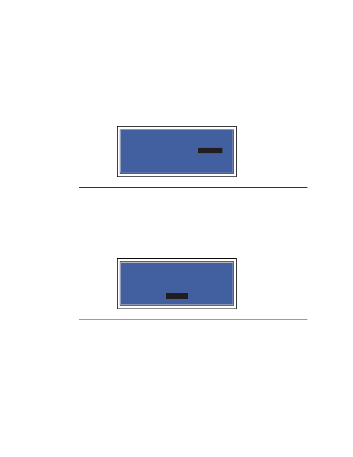
Acer M5 481/481G/481T/481TG System Utilities 2-11
Figure 2-7. Removing a Password: Set Supervisor Password
2. Type current password in Enter Current Password field and press Enter.
3. Press Enter twice
without typing anything in Enter New Password and Confirm New
Password fields. Computer will set Supervisor Password parameter to Clear.
4. Press F10 to save changes and exit the BIOS Setup Utility.
Changing a Password 0
1. Use the and keys to highlight Set Supervisor Password and press Enter. The
Set Supervisor Password dialog is shown. (Figure 2-8)
Figure 2-8. Changing a Password: Set Supervisor Password
2. Type current password in Enter Current Password field and press Enter.
3. Type new password in Enter New Password field and pr e ss Enter.
4. Retype new password in Confirm New Password field and press Enter.
5. If new password and confirm ne w p assword str ings match, The Setup Notice dialog is
shown (Figure 2-9). If it is not shown, go to step 6.
Figure 2-9. Changing a Password: Setup Notice
a. Press Enter to return to the BIOS Setup Utility Security menu.
b. The Supervisor Password parameter is shown as Set.
c. Press F10 to save changes and exit BIOS Setup Utility.
6. If current password and new password strings do not match, the Setup Warning dialog
is shown (Figure 2-10). If it is not shown, go to step 7.
Set Supervisor Password
Enter Current Password [ ]Enter Current Password
Enter New Password [ ]
Confirm New Password [ ]
Setup Notice
Changes have been saved.
[Continue]Continue
Page 66
2-12 Acer M5 481/481G/481T/481TG System Utilities
Figure 2-10. Changing a Password: Invalid Password
a. Press Enter to return to the BIOS Setup Utility Security menu.
b. The Supervisor Password parameter is shown as Clear.
c. To try to change the password again, repeat steps 1 through 4.
7. If new password and confirm new password strings do not match, the Setup Warning
dialog is shown (Figure 2-1 1).
Figure 2-11. Changing a Password: Passwords Do Not Match
a. Press Enter to return to the BIOS Setup Utility Security menu.
b. The Supervisor Password parameter is shown as Clear.
c. To try to change the password again, repeat steps 1 through 4.
Setup Warning
Invalid Password.
[Continue]Continue
Setup Warning
Passwords do not match.
Re-enter password.
[Continue]Continue
Page 67
Acer M5 481/481G/481T/481TG System Utilities 2-13
Boot 0
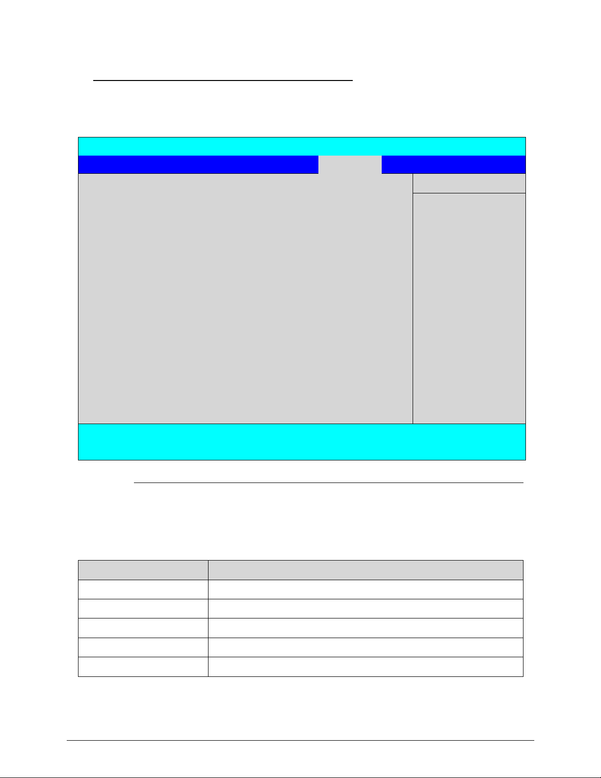
The Boot tab allows changes to the order of boot devices used to load the operating system.
Bootable devices include the:
USB diskette drives
Onboard hard disk drive
DVD drive in the module bay
Use and keys to select a device and press F5 or F6 to change the value.
Figure 2-12. BIOS Boot
InsydeH20 Setup Utility Rev. 3.5
Information Main Security Boot Exit
Item Specific Help
Boot priority order:
USe <> or <> to
select a device, then
press <F5> to move it
down the list, or <F6>
to move it up the list.
Press <Esc> to escape
the menu.
1. HDD: Hitachi HTS545032B9A300
2. ATAPI CDROM: MATSHITADVD-RAM UJ8A2AS
3. USB FDD:
4. Network Boot: Atheros Boot Agent
5. USB HDD:
6. USB CDROM:
F1 Help Select Item F5/F6 Change Values F9 Setup Default
ESC Exit Select Menu Enter Select>SubMenu F10 Save and Exit
Page 68
2-14 Acer M5 481/481G/481T/481TG System Utilities
Exit 0
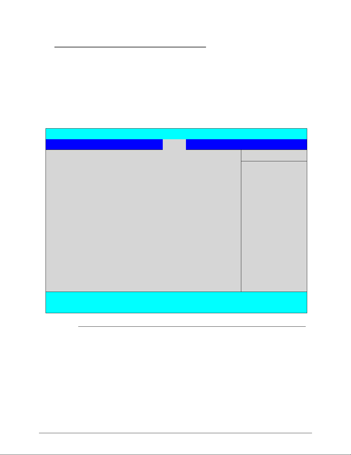
The Exit tab allows users to save or discard changes and quit the BIOS Setup Utility.
Figure 2-13. BIOS Exit
Table 2-4 describes the parameters in Figure 2-13.
InsydeH20 Setup Utility Rev. 3.5
Information Main Security Boot Exit
Item Specific Help
Exit Saving Changes
Exit System Setup and
save your changes.
Exit Discard Changes
Load Setup Defaults
Discard Changes
Save Changes
F1 Help Select Item F5/F6 Change Values F9 Setup Default
ESC Exit Select Menu Enter Select>SubMenu F10 Save and Exit
Table 2-4. BIOS Exit
Parameter Description
Exit Saving Changes Exit BIOS utility and save setup item changes to system.
Exit Discarding Changes Exit BIOS utility without saving setup item changes to system.
Load Setup Defaults Load default values for all setup items.
Discard Changes Load previous values of all setup items.
Save Changes Save setup item changes to system.
Page 69

Acer M5 481/481G/481T/481TG System Utilities 2-15
BIOS Flash Utilities 0
BIOS Flash memory updates are required for the following conditions:
New versions of system programs
New features or options
Restore a BIOS when it becomes corrupted.
Use the Flash utility to update the system BIOS Flash ROM.
NOTE:
NOTE:
If a Crisis Recovery Disc is not available, create one before BIOS Flash utility is used.
NOTE:
NOTE:
Do not install memory related drivers (XMS, EMS, DPMI) when BIOS Flash is used.
NOTE:
NOTE:
Use AC adaptor power supply when running BIOS Flash utility . If battery pack does not
contain power to finish loading BIOS Flash, do not boot system.
Prerequisites for BIOS Flashing utilities:
1. Prepare a bootable USB device.
2. Copy Flash utilities to bootable USB device.
3. Boot system from bootable USB device.
NOTE:
NOTE:
BIOS Flash utility has auto execution function.
Page 70
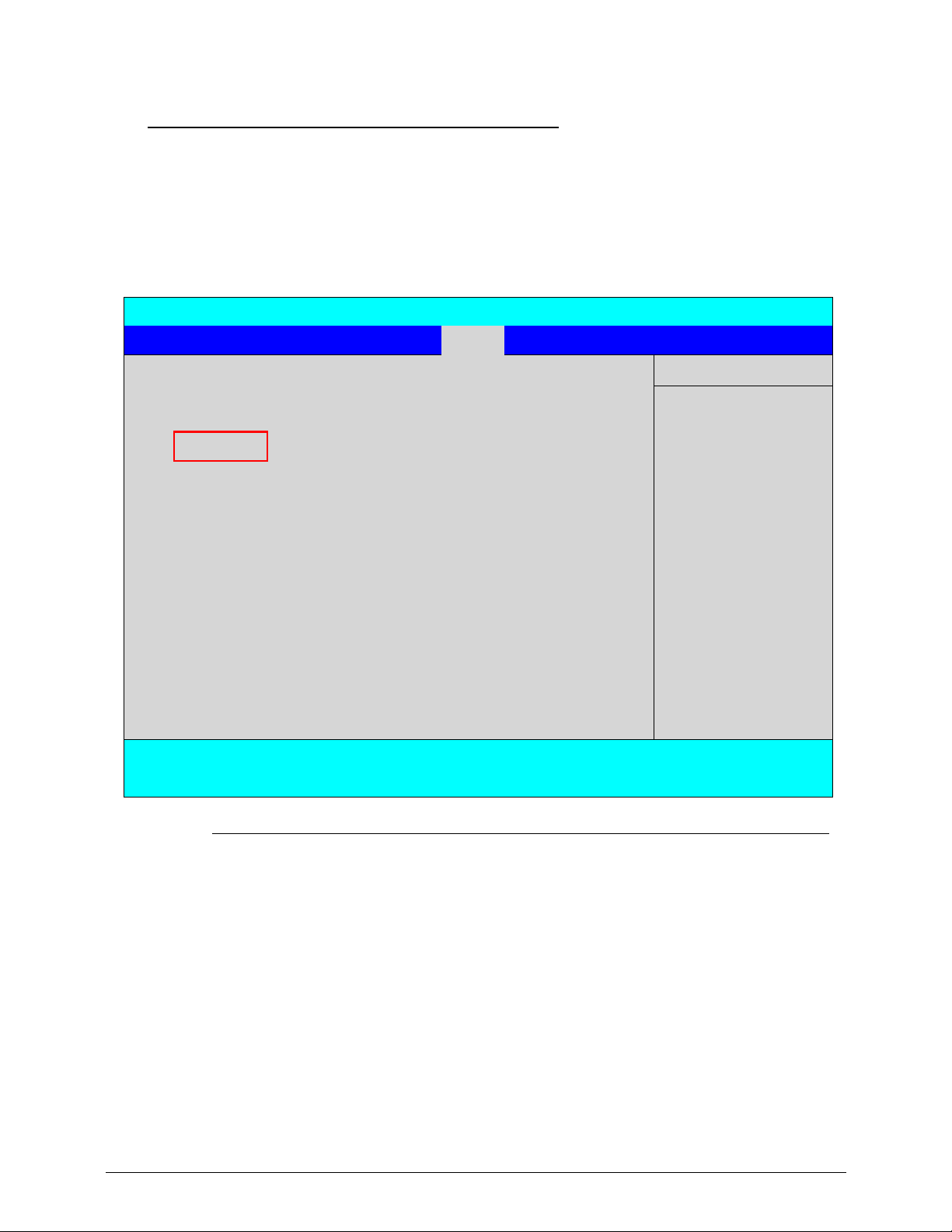
2-16 Acer M5 481/481G/481T/481TG System Utilities
DOS Flash Utility 0
Perform the following to use the DOS Flash Utility:
1. Press F2 during boot to enter Setup Menu.
2. Select Boot Menu to modify boot priority order.
3. Move USB HDD to position 1 (Figure 2-14). (Refer to Boot menu)
Figure 2-14. Change BIOS Boot Priority Order
4. Copy Z09_022.exe to USB device, and insert device into a system port.
5. Boot to DOS mode.
6. Execute Z09_022.exe to update BIOS. (Figure 2-15, where C: is the name of the USB
drive)
The system restarts after update is complete.
InsydeH20 Setup Utility Rev. 3.5
Information Main Security Boot Exit
Item Specific Help
Boot priority order:
USe <> or <> to
select a device, then
press <F5> to move it
down the list, or <F6>
to move it up the list.
Press <Esc> to escape
the menu.
1. USB HDD: USB 2.0 Flash Disk
2. IDE0: WDC WD 2500B PVT-22ZEST0
3. IDE1:
4. USB FDD:
5. Network Boot: Atheros Boot Agent
6. USB CDROM:
F1 Help Select Item F5/F6 Change Values F9 Setup Default
ESC Exit Select Menu Enter Select>SubMenu F10 Save and Exit
Page 71
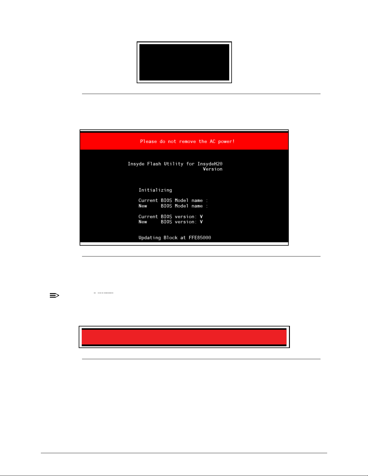
Acer M5 481/481G/481T/481TG System Utilities 2-17
Figure 2-15. Executing ZRJ_0.08
BIOS flash process begins. (Figure 2-16)
Figure 2-16. Updating Flash ROM Blocks
7. Flash is complete when the message, Flash Programming Complete is shown.
System will restart automatically when finished.
NOTE:
NOTE:
If AC power is not connected, the following message is shown (Figure 2-17). Plug in the
AC power to continue.
Figure 2-17. AC Power Warning
C:\>Z09_022
X.XXx
XXXXXXXX
XXXXXXXX
XXXXXXXX
XXXXXXXX
Z09
Z09
0.05
0.08
1.4c
Warning: No AC power connect
Page 72
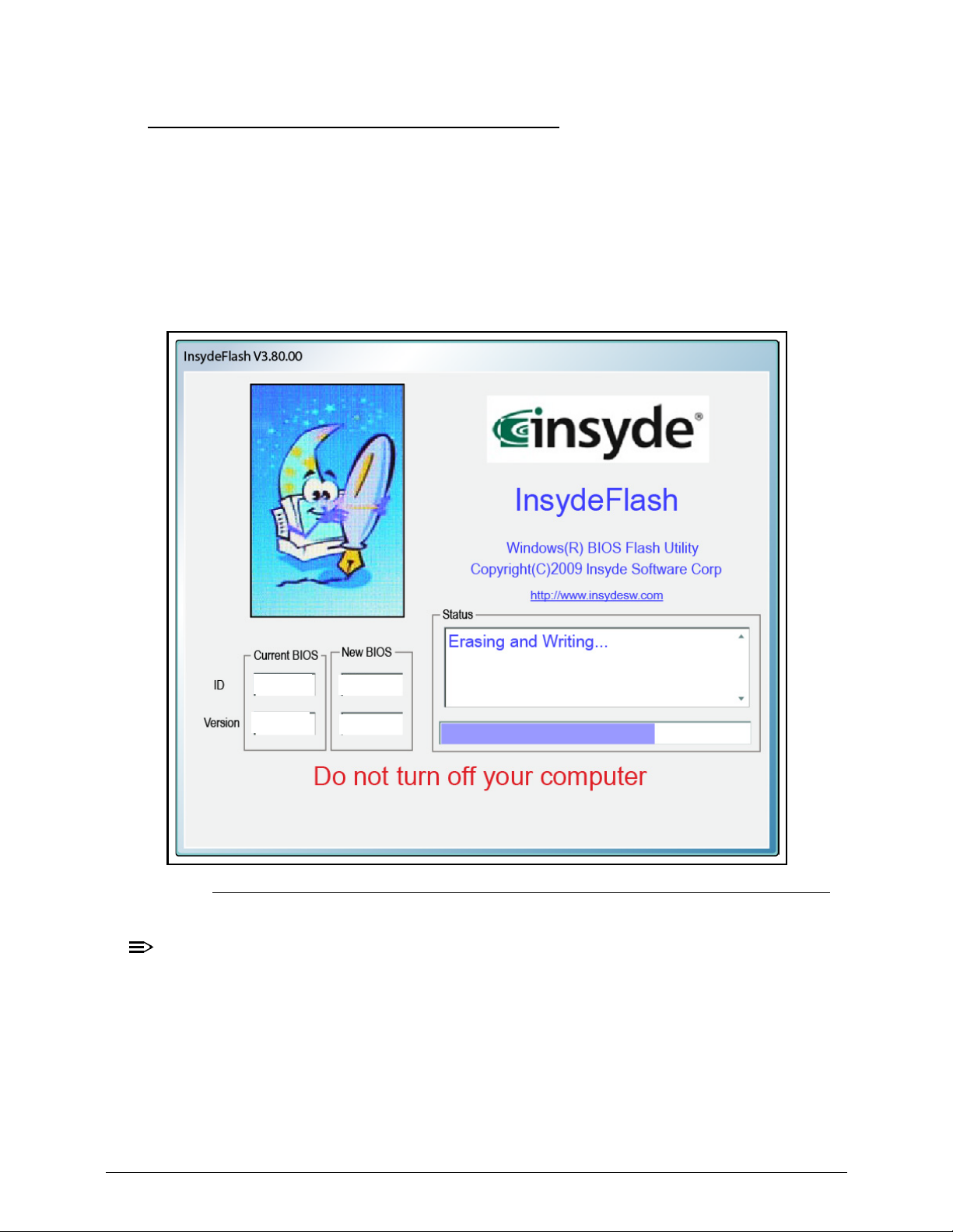
2-18 Acer M5 481/481G/481T/481TG System Utilities
WinFlash Utility 0
Perform the following to use the WinFlash Utility:
1. Boot to Windows OS.
2. Copy Z09_022W.exe (WinFlash Executable) to the Desktop--recommended for easy
access.
3. Double click the WinFlash executable.
4. Click OK to begin the update. A progress screen is shown. (Figure 2-18)
Figure 2-18. InsydeFlash
NOTE:
NOTE:
If the error message appears (Figure 2-19), check the system BIOS ROM-file size.
ZRJ
ZRJ
V0.05
V0.08
Page 73
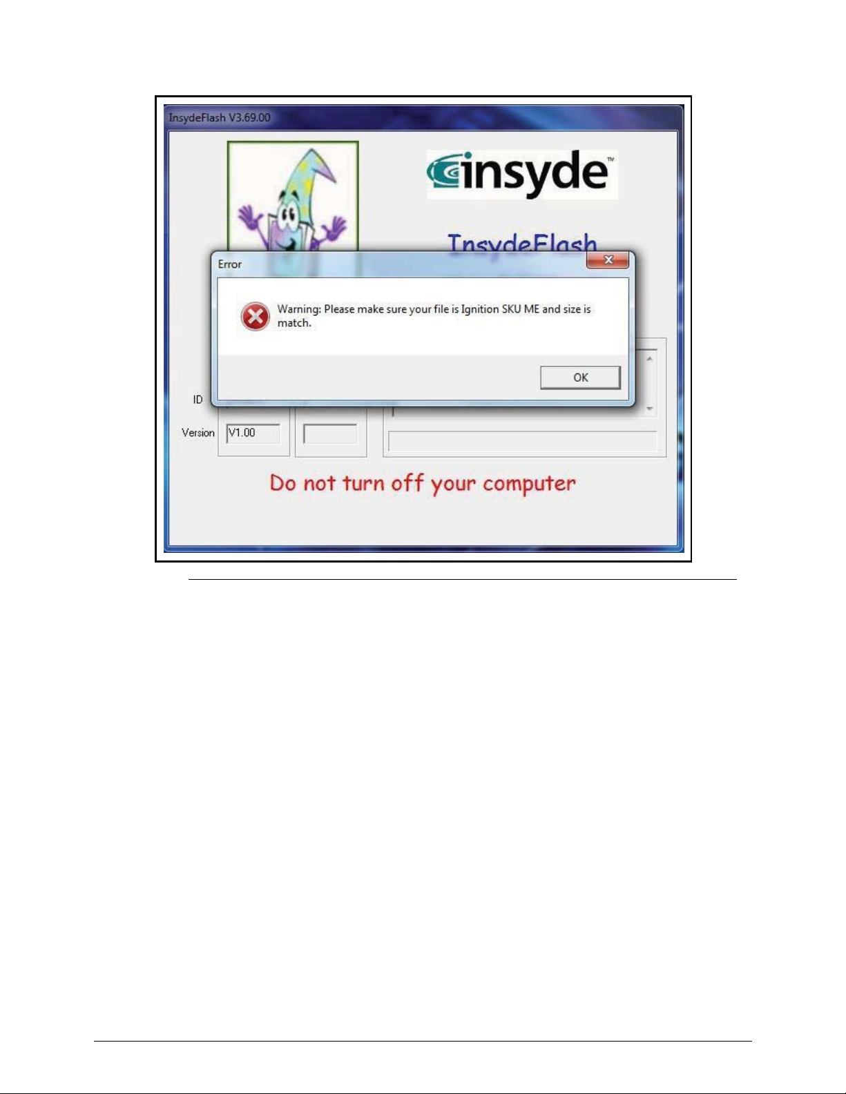
Acer M5 481/481G/481T/481TG System Utilities 2-19
Figure 2-19. InsydeFlash
Page 74
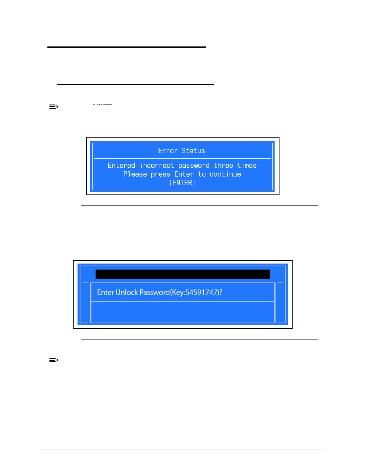
2-20 Acer M5 481/481G/481T/481TG System Utilities
Remove Password Utilities 0
This section provides details about removing HDD/BIOS passwords.
Remove HDD Password 0
Remove HDD Password as follows:
NOTE:
NOTE:
If the HDD password is incorrectly entered three times, an error is generated.
(Figure 2-20)
Figure 2-20. Password Error Status
To remove the HDD password, perform the following:
1. From Password Error Status dialog shown in Figure 2-20, press Enter to continue.
2. The Enter Unlock Password dialog (Figure 2-21) is shown.
Figure 2-21. Enter Unlock Password Key
NOTE:
NOTE:
An key code is generated for use with unlocking utility. Make note of this code.
3. On separate, compatible device, boot to DOS.
4. Execute UnlockHD.exe (Figure 2-22) to create a password unlock code. Use the format
<UnlockHD [key code]> with the code noted in the Figure 2-21.
Example: UnlockHD 54591747
The command generates a password which can be used for unlocking the HDD.
Example: Password: 41499389
Page 75
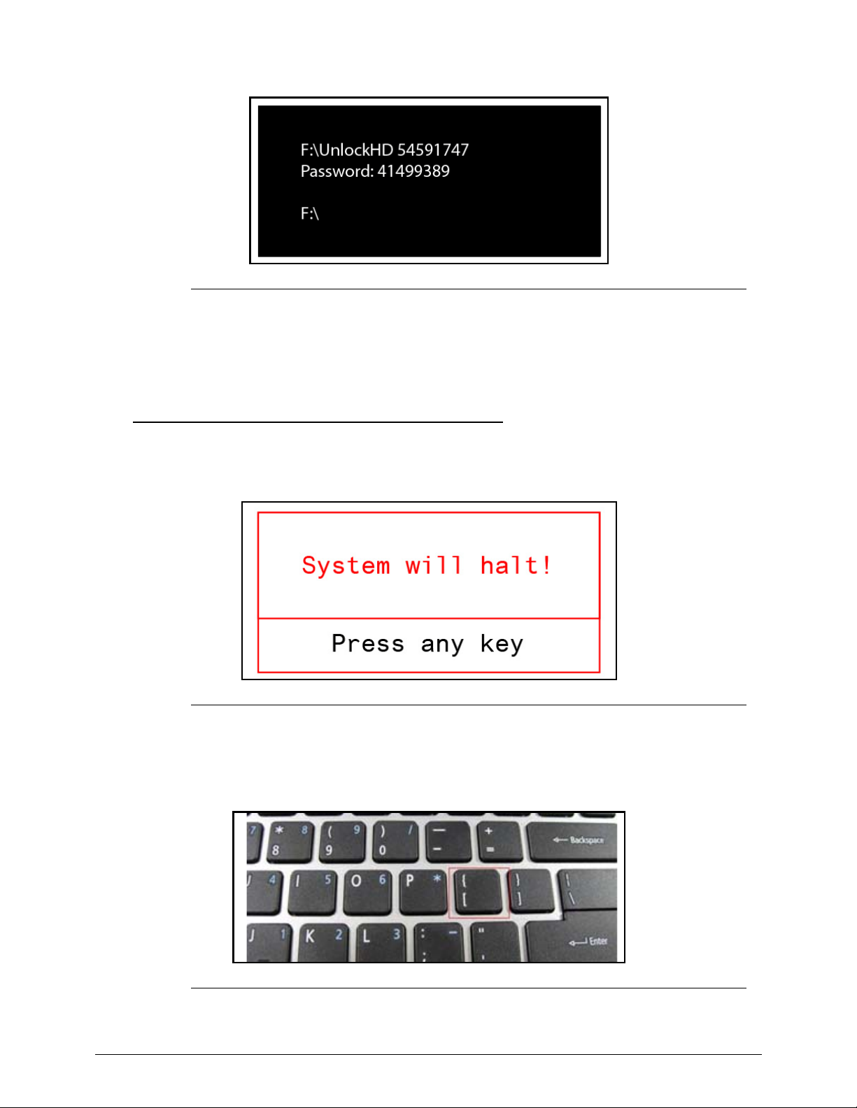
Acer M5 481/481G/481T/481TG System Utilities 2-21
Figure 2-22. Unlock Password
5. On original device, enter password (Figure 2-22) in Enter Unlock Password dialog
(Figure 2-21).
Removing BIOS Password 0
If wrong supervisor password is entered three times, the System will halt! dialog is
shown. (Figure 2-23)
Figure 2-23. Supervisor Password Error
1. Press the Power button
2. Press the “[“ key at Post.
Figure 2-24. Enter “[“ Key at Post
Page 76
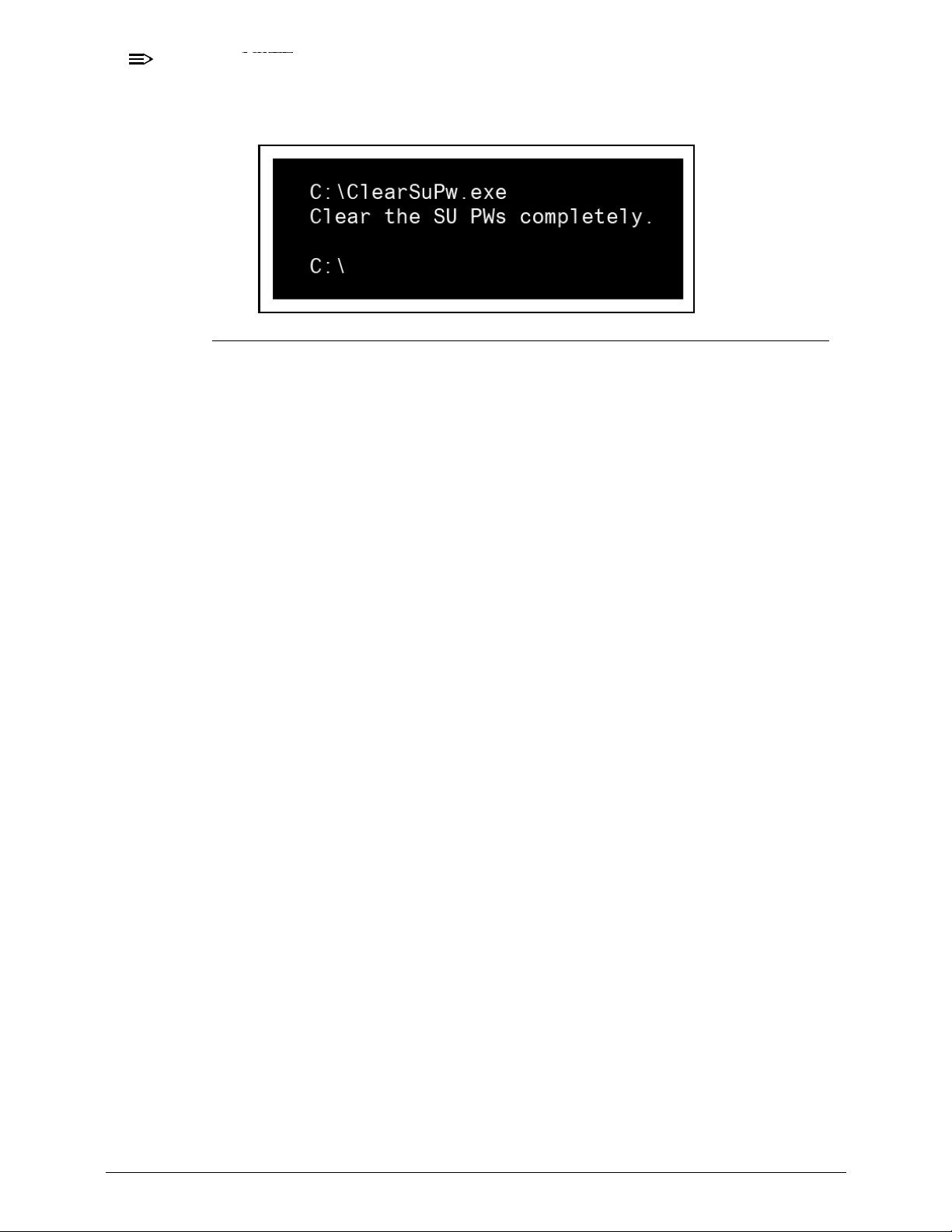
2-22 Acer M5 481/481G/481T/481TG System Utilities
3. In the Boot Option Menu, select USB HDD: to boot from a USB device.
NOTE:
NOTE:
The Password on Boot setting must be Disabled in BIOS setup.
4. At a DOS prompt, enter ClearSuPw.exe. (Figure 2-25)
Figure 2-25. Clear Supervisor Password Utility
5. When message Clear the SU Pws completely is shown, supervisor password has
been removed.
Page 77
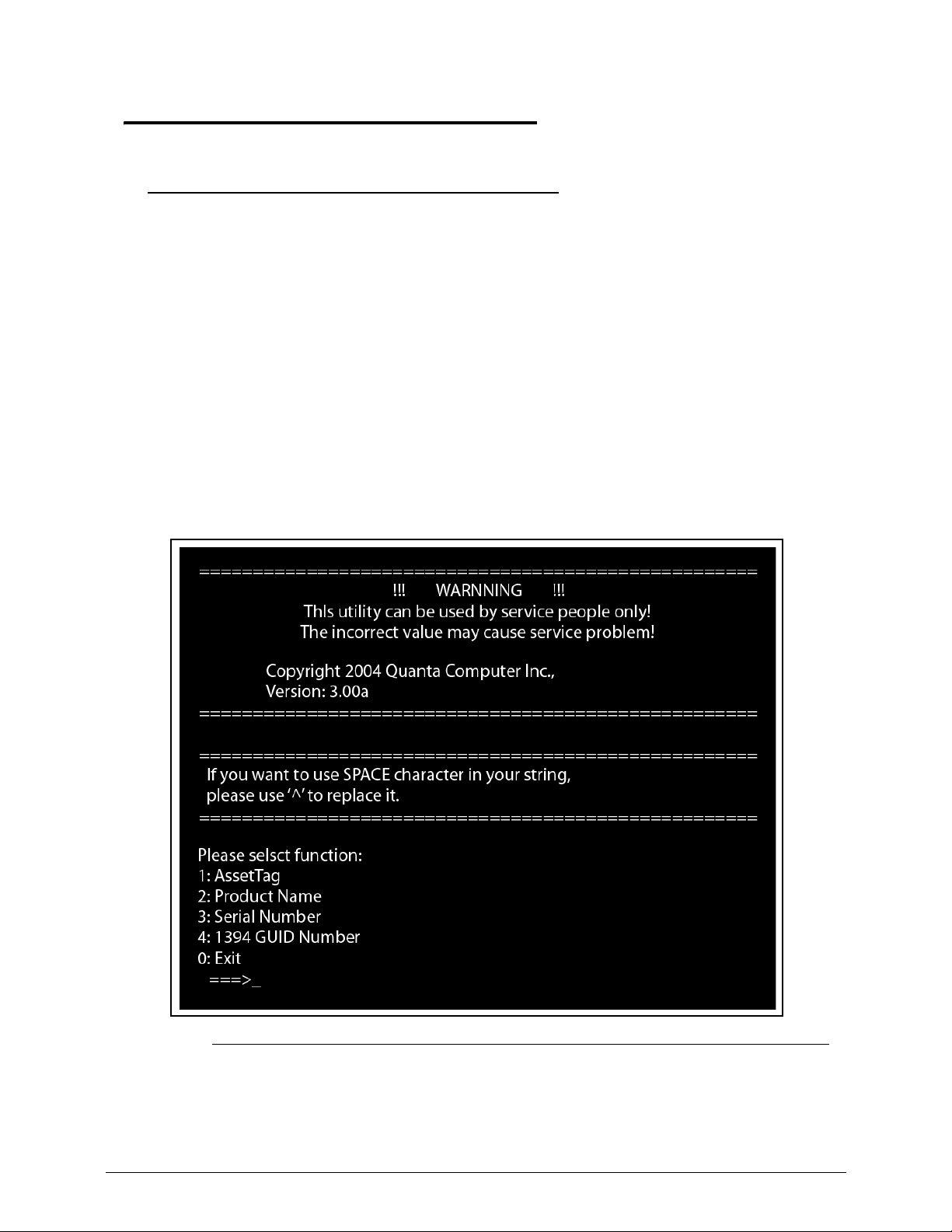
Acer M5 481/481G/481T/481TG System Utilities 2-23
Miscellaneous Tools 0
Using DMI Tools 0
The DMI (Desktop Man agement Interface) Tool copies BIOS information to EEPROM. Used in
the DMI pool for hardware management.
When the BIOS shows Verifying DMI pool data, it is checking that the table correlates
with the hardware before sending it to the operating system (Windows, etc.).
Prerequisites:
Copy qdmi301.exe and VEEPROM to a bootable USB device
To update the DMI Pool, perform the following:
1. Insert USB device in system.
2. Boot to DOS.
3. At the prompt, enter qdmi301.exe.
To execute a specific function, select the associated menu
number. (
Figure 2-26)
Figure 2-26. DMI Tools Main Menu Screen
4. Press 1 to modify asset tag key. (Figure 2-27)
Page 78
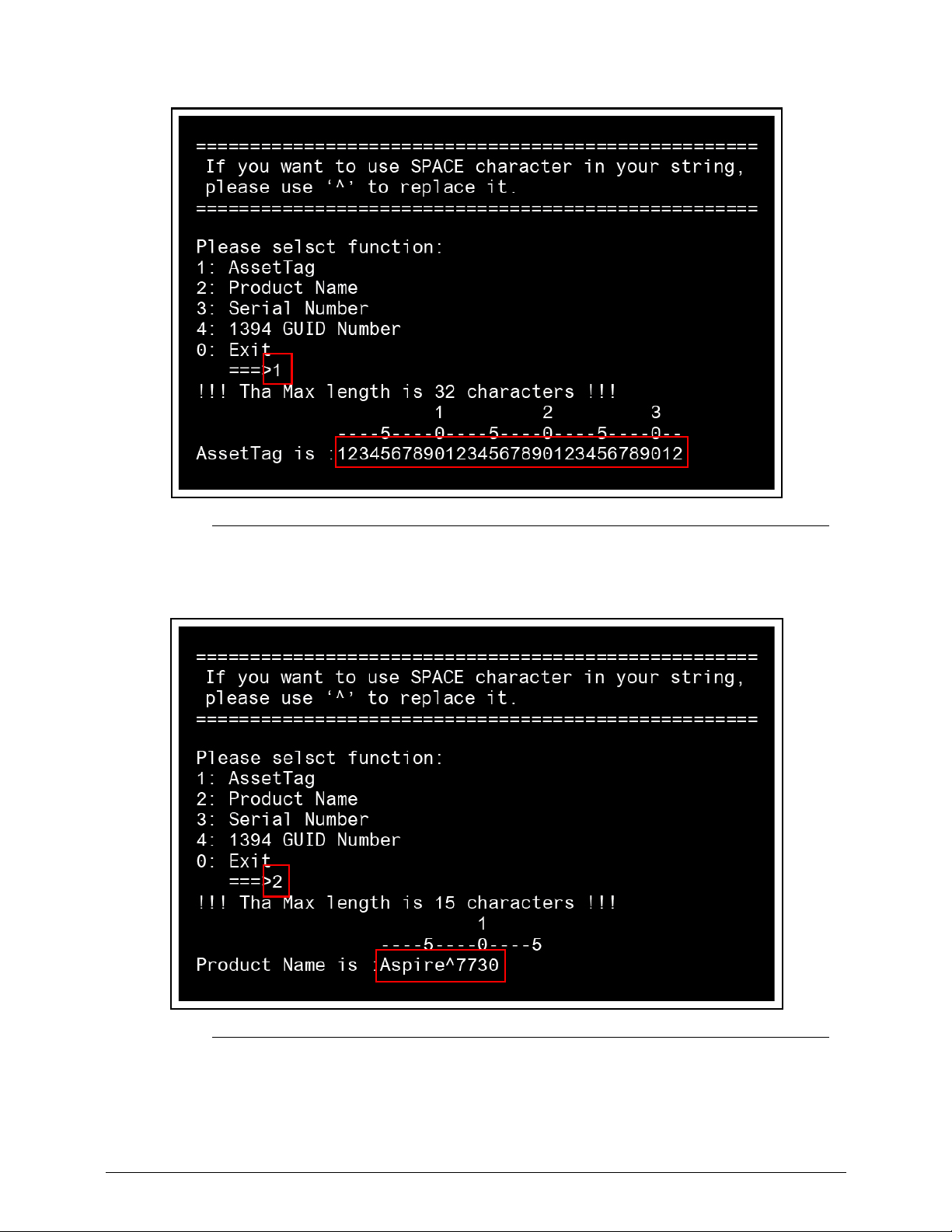
2-24 Acer M5 481/481G/481T/481TG System Utilities
Figure 2-27. Asset Tag Menu Item
5. Press 2 to modify the product number key. (Figure 2-28)
Figure 2-28. Product Name Menu Item
6. Press 3 to modify serial number key.
Page 79
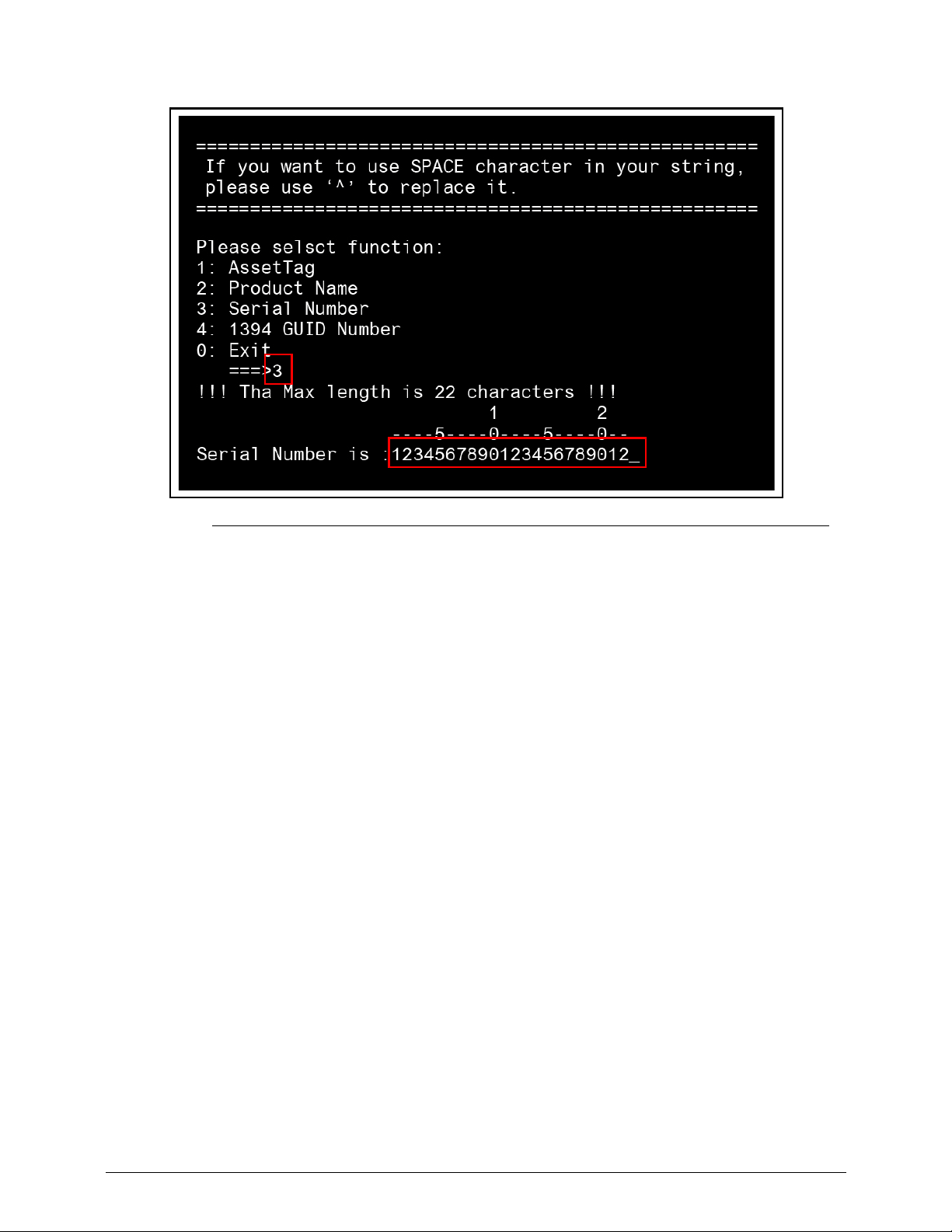
Acer M5 481/481G/481T/481TG System Utilities 2-25
Figure 2-29. Serial Number Menu Item
7. Press 4 to modify the 1394 GUID number key.
Page 80
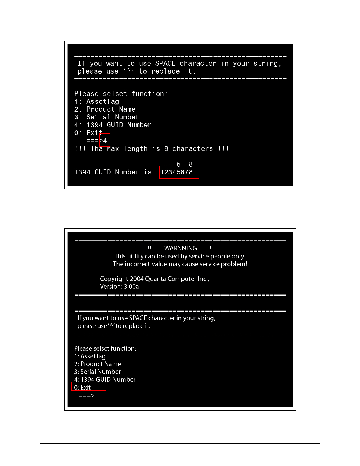
2-26 Acer M5 481/481G/481T/481TG System Utilities
Figure 2-30. 1394 GUID Number Menu Item
8. Press 0 to exit.
Page 81
Acer M5 481/481G/481T/481TG System Utilities 2-27
Figure 2-31. Exit Menu Item
9. At the command prompt, type VEEPROM to write any changes in the data to the
EEPROM.
Figure 2-32. VEEPROM Command Prompt
NOTE:
NOTE:
When using any of the write options, restart the system to make the new DMI data
effective.
C:\VEEPROM_
Page 82
2-28 Acer M5 481/481G/481T/481TG System Utilities
Using the LAN MAC EEPROM Utility 0
Use MAC.BAT utility to write the MAC.CFG file to EEPROM under DOS mode.
1. Use a text editor (e.g. Notepad) to open and edit the MAC.CFG file. (Figure 2-33)
Figure 2-33. MAC.CFG File
2. In DOS mode, run MAC.BAT to write MAC values to eeprom. (Figure 2-34)
Figure 2-34. MAC.BAT
3. Reboot computer when process has completed.
Table 2-5.
Field Name Value Description
Title MAC Address
byte
N/A
WriteData 001122334455 MAC value
StartAddr 7A MAC address
WriteLeng 6 MAC value length
KeepByte 0 N/A
MAC.CFG - Notepad
MAC.CFG - Notepad
Title= MAC Address byte
WriteData=’001122334455’
StartAddr=7A
WriteLeng=6
KeepByte=0
File Edit Format View Help
C:\MAC>mac.bat
C:\MAC>eeprom w MAC.cfg
Progress --> \
Write Data to EEPROM OK!!
Page 83

CHAPTER 3
Maintenance Procedures
Page 84

3-2
Page 85
Maintenance Procedures 3-3
Maintenance Procedures
Introduction 0
This chapter contains general info rmation about the notebook, a list o f tools needed to perform
the required maintenance and step by step procedures on how to remove and install
components from the notebook computer.
General Information 0
The product previews seen in the following procedures may not represent the final product
color or configuration. Cable paths and positioning may also differ from the actual model.
During the removal and installation of components, make sure all available cable channels
and clips are used and that the cables are inst alled in the same position. All prerequisites must
be performed prior to performing maintenance.
Recommended Equipment 0
The following tools are required to perform maintenance on the notebook:
Wrist grounding strap and conductive mat
Flat screwdriver
Philips screwdriver
Screw Table 0
The following screw table provides a list of all required screws to assemble the computer.
Table 1-1. Main Screw List
Screw Name Quantity
M1.4x1.0 31
M2.5x6.0 16
M2.5x4.0 9
M2.0x3.0 5
M2.0x2.5 2
M3.0x3.5 2
M2.5x2.0 12
M2.0x2.0 1
Page 86
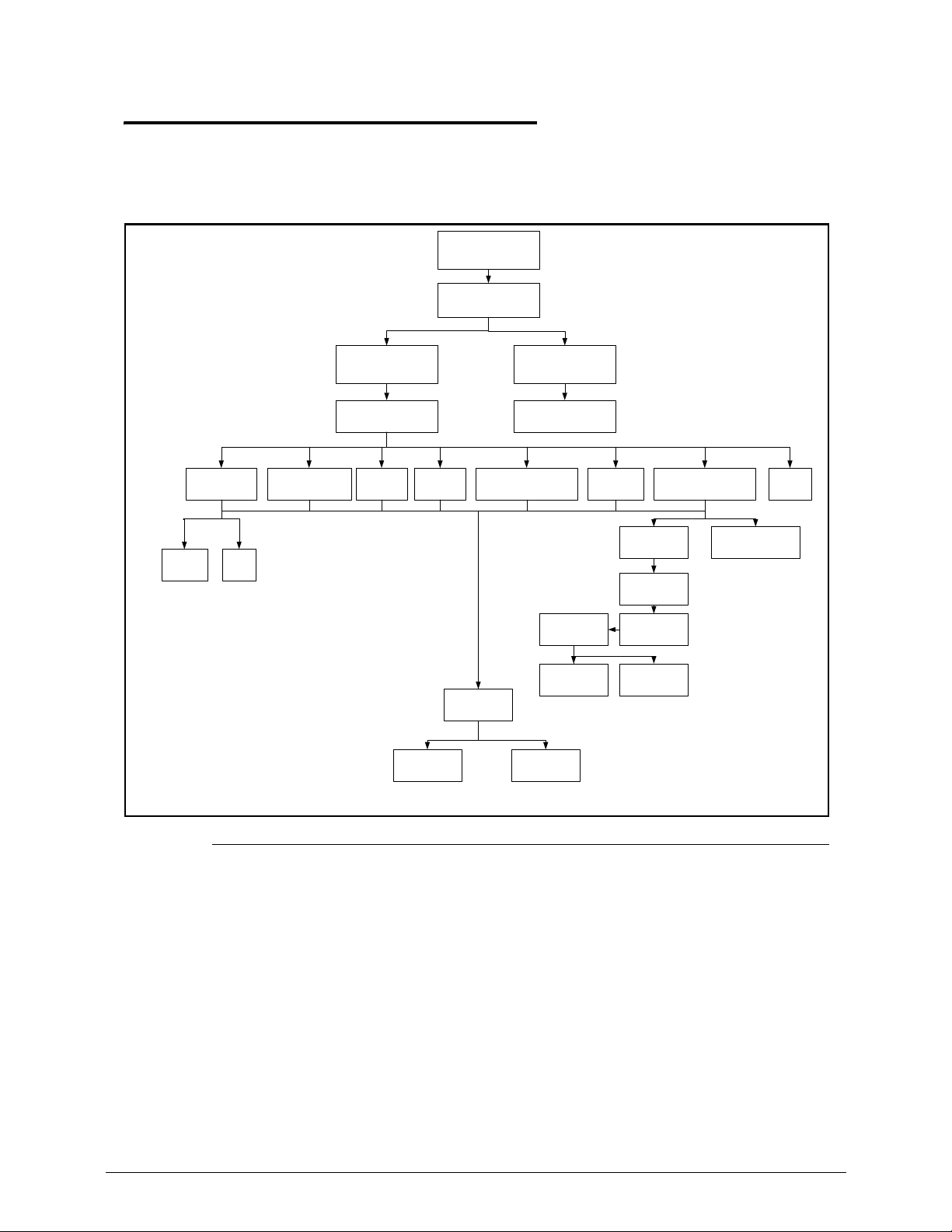
Maintenance Procedures 3-4
Maintenance Flowchart 0
The flowchart in Figure 3-1 provides a graphic representation of the module removal and
installation sequences. It provides information on what componen ts need to be removed and
installed during servicing.
Figure 3-1. Maintenance Flow
! " #
$ %
&'
#:
%&;
#;#&
#<
&
;
=#'">
!&&&;
?$
Page 87
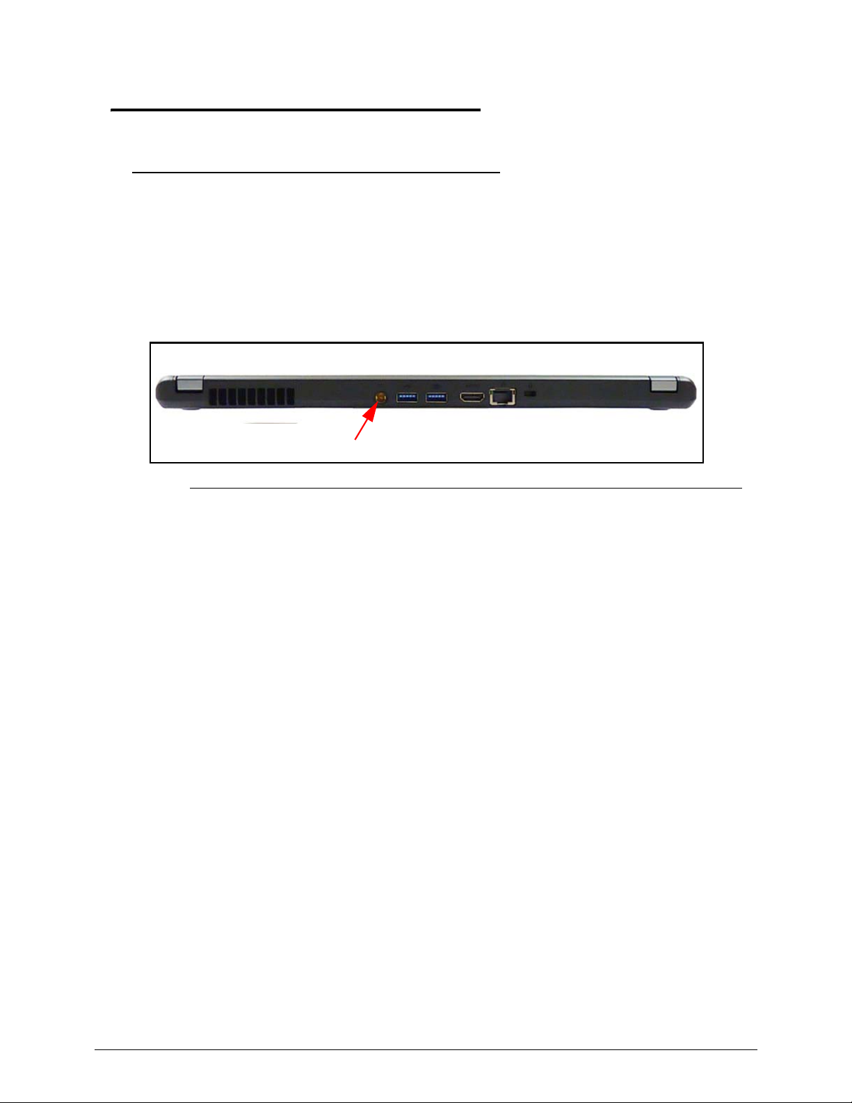
3-5
Machine Disassembly 0
Getting Started 0
The flowchart (Figure 3-1) identifies sections illustrating the entire removal and install
sequence. Observe the order of the sequence to avoid damage to any of the hardware
components.
Perform the following prior to performing any maintenance procedures:
1. Remove power (A) from the system and peripherals. (Figure 3-1)
2. Remove all cables from system.
Figure 3-1. AC Adapter
3. Place system on a stable work surface.
A
Page 88
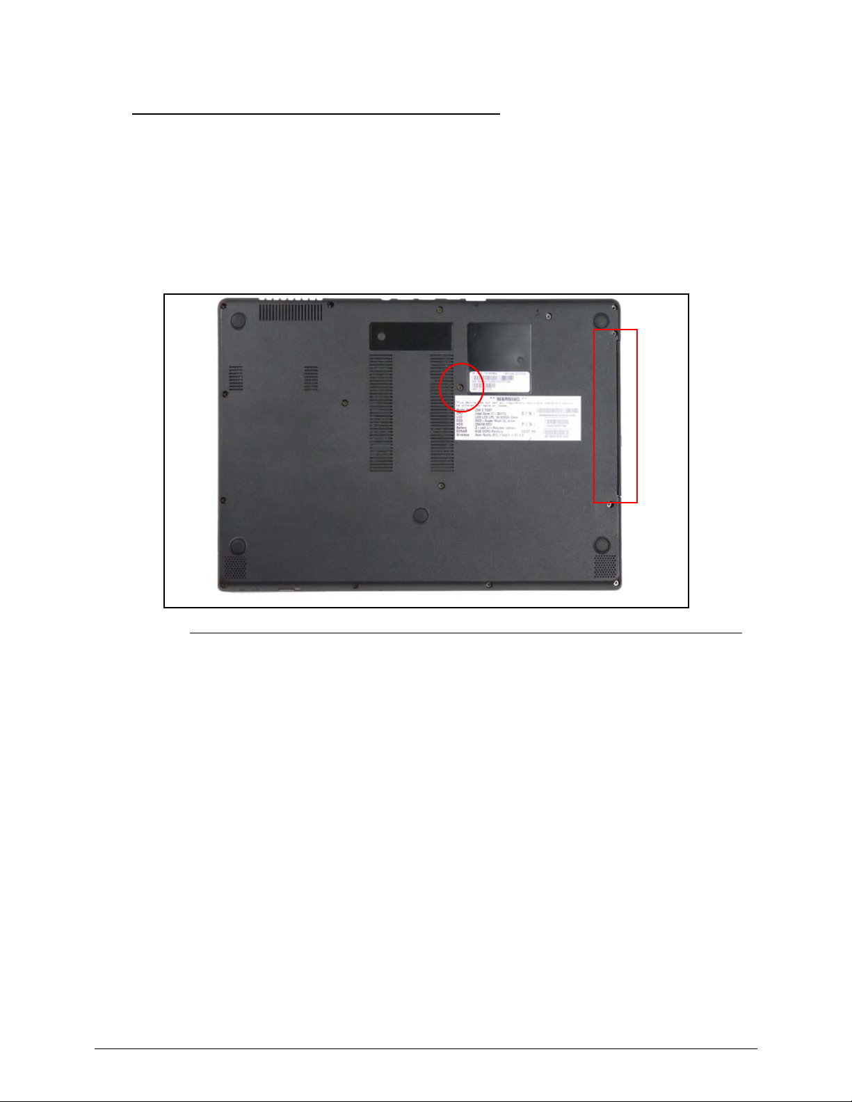
3-6
ODD Module Removal 0
Prerequisite:
Disconnect AC adapter
Turn off device
1. Locate ODD Module on lower cover. (Figure 3-1)
2. Remove screw.
Figure 3-1. ODD Module Removal
3. Remove ODD module from lower cover.
4. Insert a thin tool in the manual eject hole to open the drive.
5. Remove the ODD bezel (Figure 3-2).
Page 89
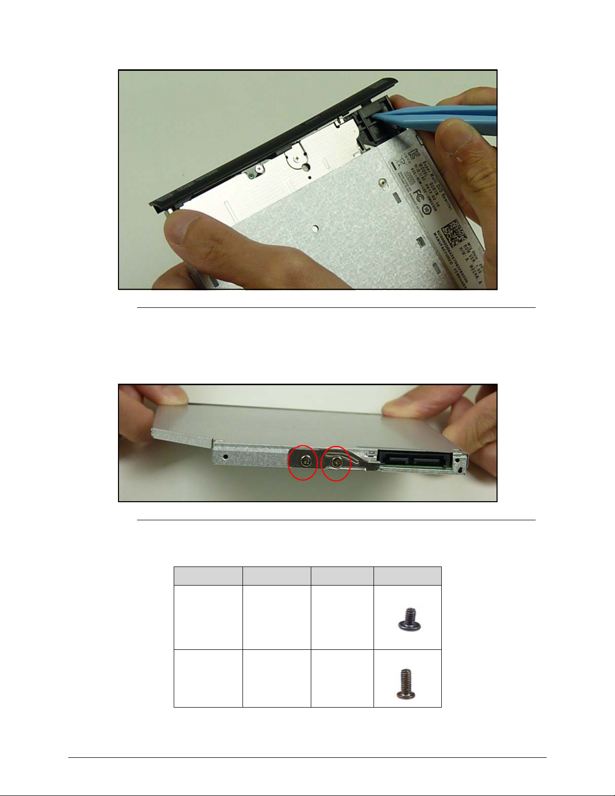
3-7
Figure 3-2. ODD Bezel Removal
6. Remove screws from the bracket.
7. Remove the bracket.
Figure 3-3. ODD Bracket Removal
ID Size Quantity Screw Type
AM2x2 2
B M2.5x5.0 1
Page 90
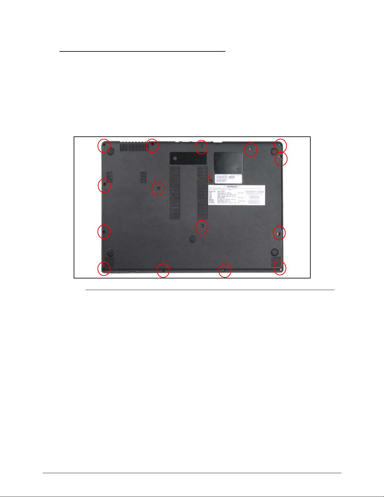
3-8
Lower Cover Removal 0
The lower cover is attached to the mainboard. The lower cover screws are removed to allow
access to:
Top Cover
Prerequisite:
ODD Module Removal
1. Remove securing screw (Figure 3-1).
Figure 3-1. Lower Cover Screw Removal
2. Turn the device over on a secure surface.
3. Partially remove the top cover.
4. Disconnect the cables.
ODD Screw
Page 91
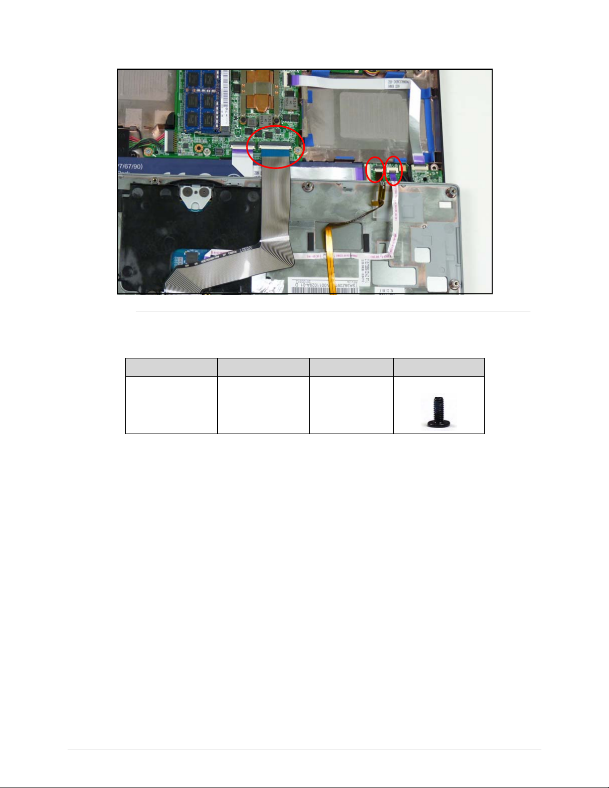
3-9
Figure 3-2. Lower Cover Cabling
ID Size Quantity Screw Type
A M2.5x5.0 15
Page 92
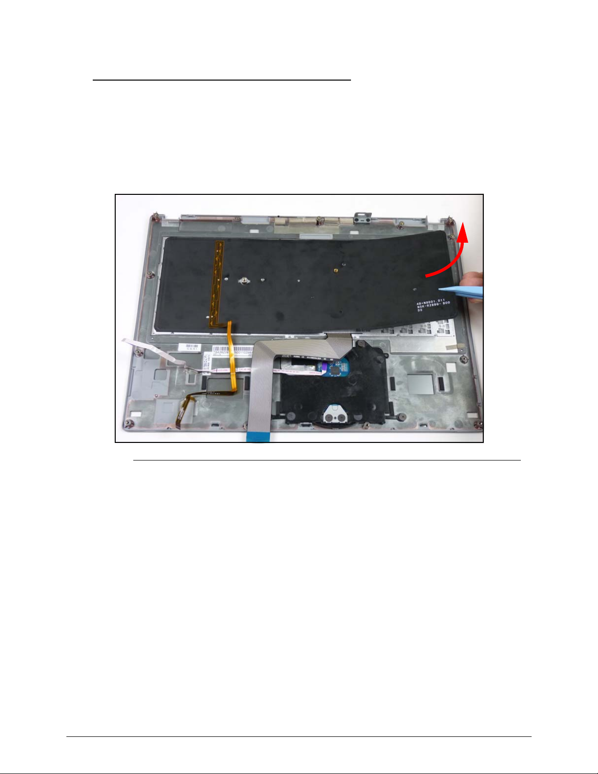
3-10
Keyboard Backlight Removal 0
Prerequisite:
Top Cover Removal
1. Turn the top cover to expose the bottom.
2. Remove the Backlight module.
Figure 3-1. Backlight Removal
Page 93
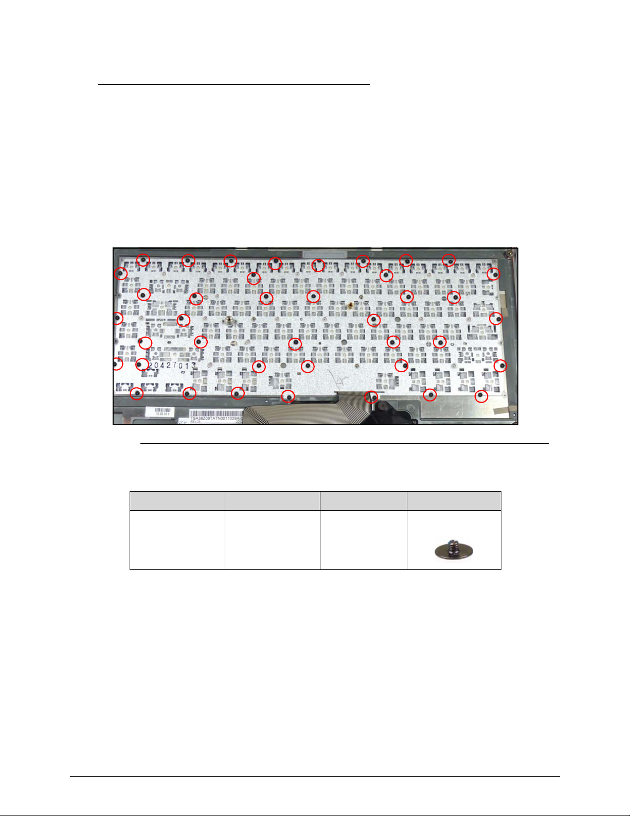
3-11
Keyboard Removal 0
Prerequisite:
Top Cover Removal
Backlight Module Removal
1. Turn the top cover to expose the bottom.
2. Remove the screw(s).
3. Lift up the keyb oard (Figure 3-1).
Figure 3-1. Keyboard Screw Removal
ID Size Quantity Screw Type
M1.0 x 0.43 40
Page 94
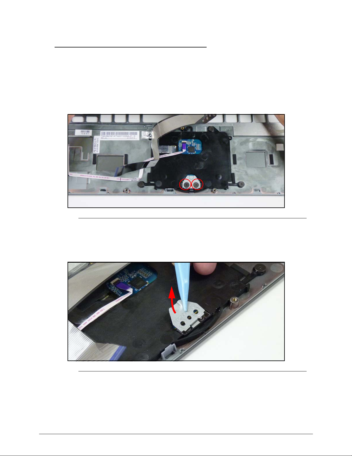
3-12
Touch Pad Bracket Removal 0
Prerequisite:
Top Cover Removal
1. Turn the top cover to expose the bottom.
2. Remove the screw(s).
Figure 3-1. T-pad Bracket Screw Removal
3. Remove the T-pad bracket.
4. Lift up the keyb oard (Figure 3-2).
Figure 3-2. T-pad Bracket Removal
Page 95
3-13
ID Size Quantity Screw Type
M2.5 x 1 x 7
(Flat head)
2
Page 96
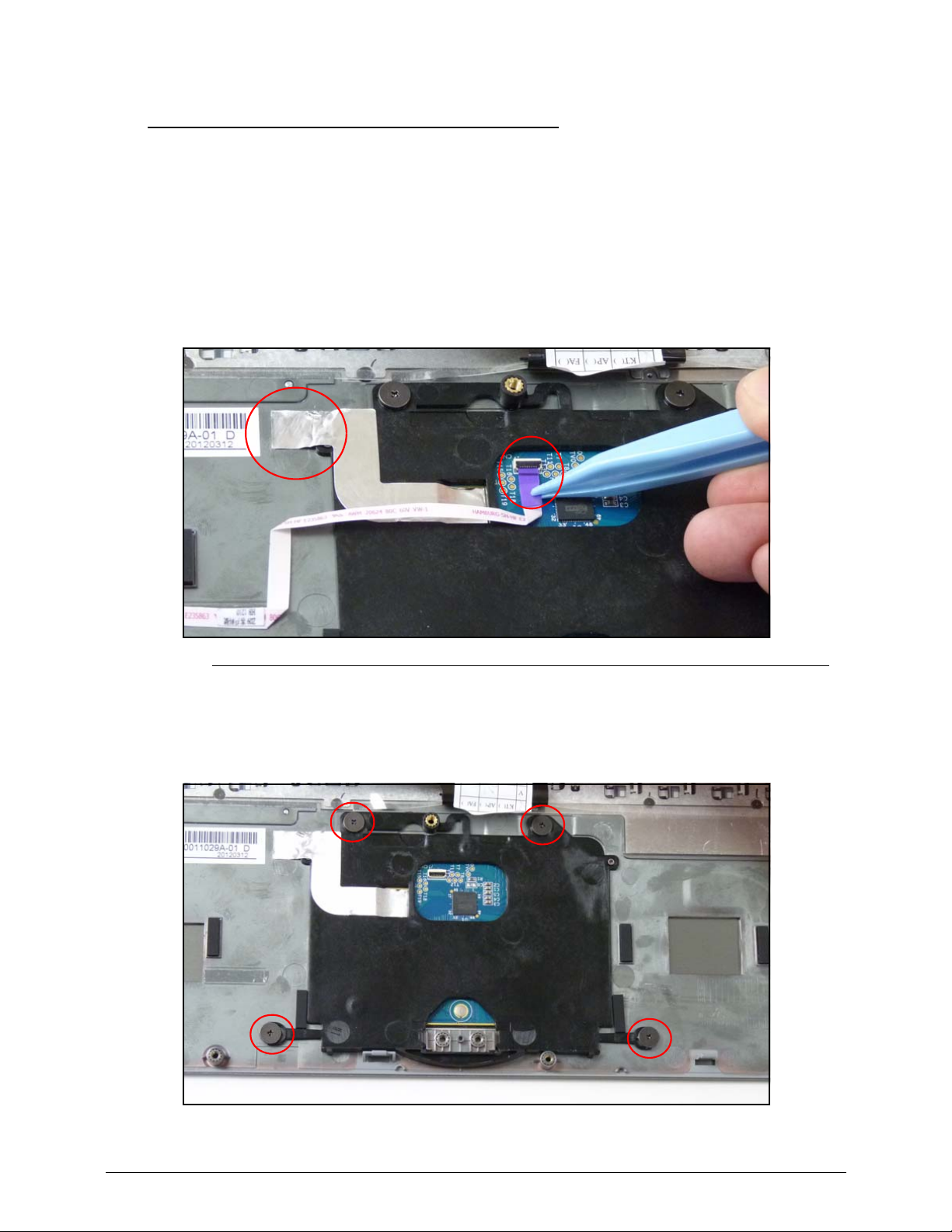
3-14
Audio Board Removal 0
Prerequisite:
Top Cover Removal
Touch Pad Bracket Removal
1. Turn the top cover to expose the bottom.
2. Disconnect the FFC and adhesive strip.
Figure 3-1. Audio Board FFC Removal
3. Remove the screw(s).
4. Remove the Audio Board.
Page 97
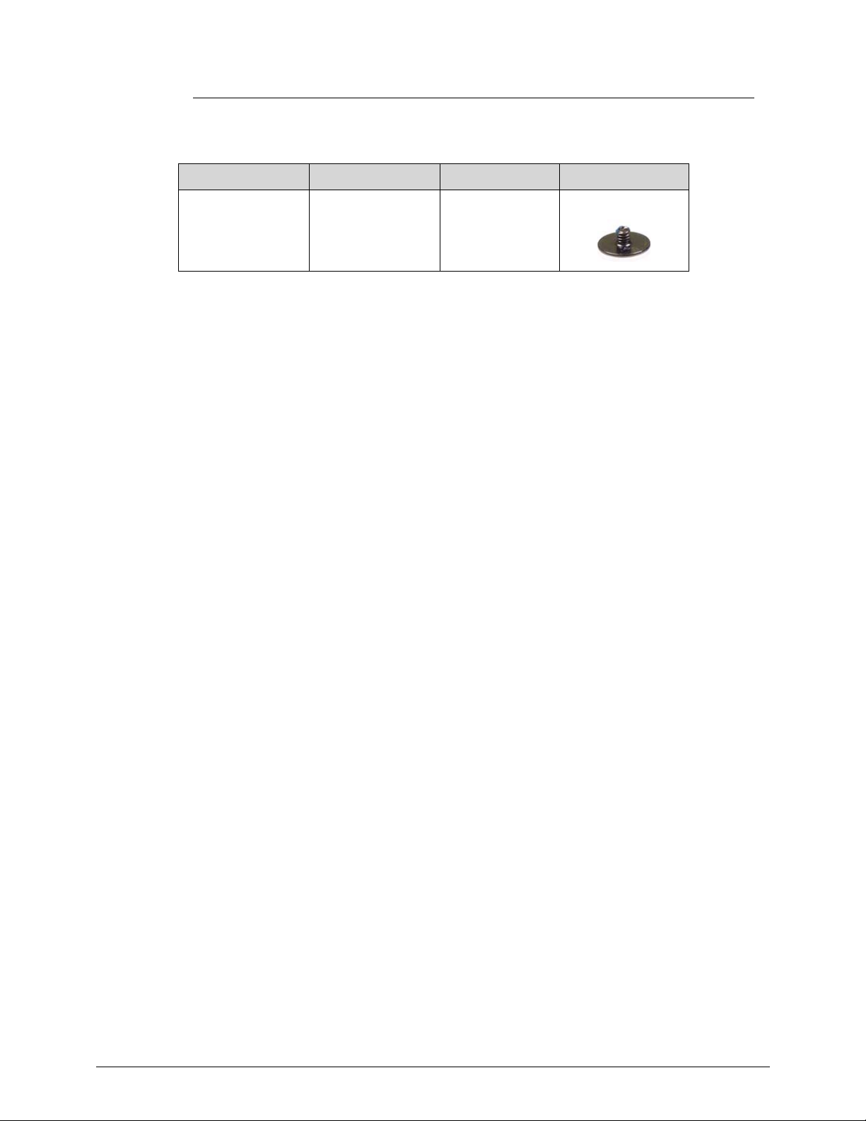
3-15
Figure 3-2. Audio Board Screw Removal
ID Size Quantity Screw Type
M2.5 x 1 x 7
(Flat head)
4
Page 98
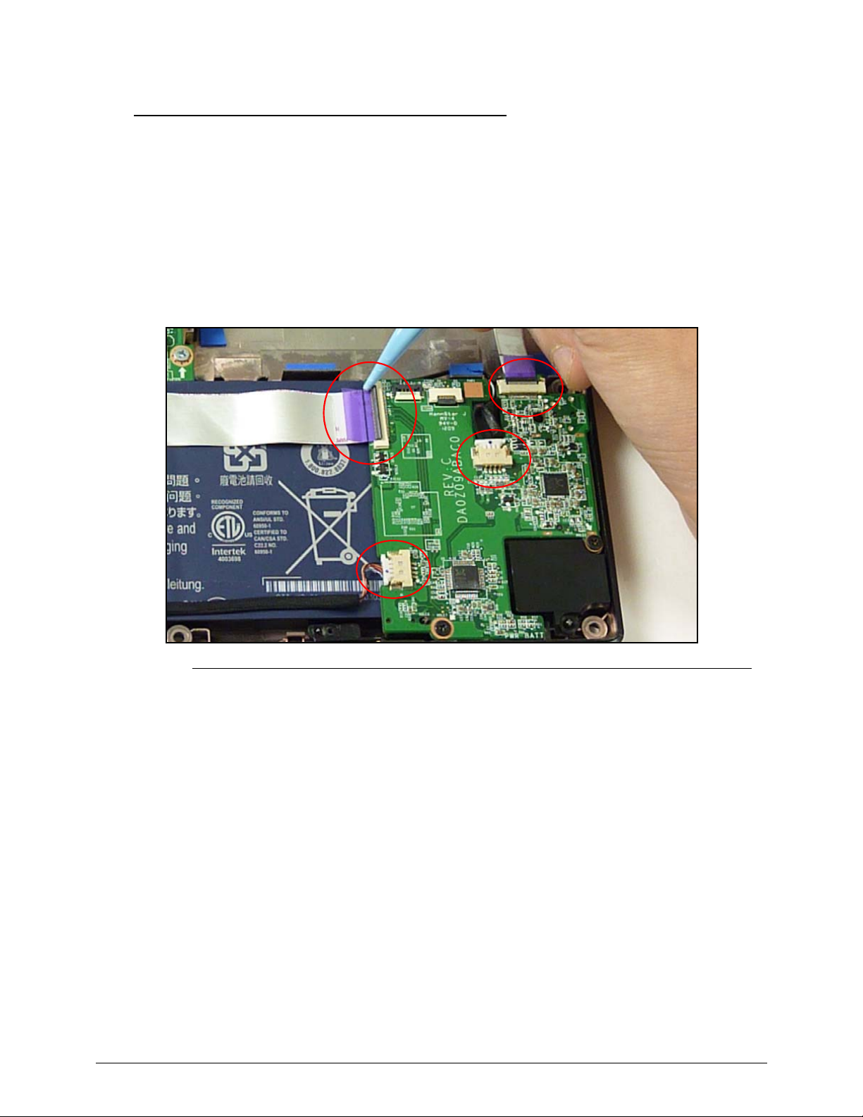
3-16
Audio Board Removal 0
Prerequisite:
Top Cover Removal
1. Disconnect the FFC from the audio board.
2. Disconnect the MIC cable from the audio board.
3. Disconnect the HDD FFC from the audio board.
4. Disconnect the speaker cable from the audio board.
Figure 3-1. Audio Board Cabling Removal
5. Remove the screw(s).
Page 99
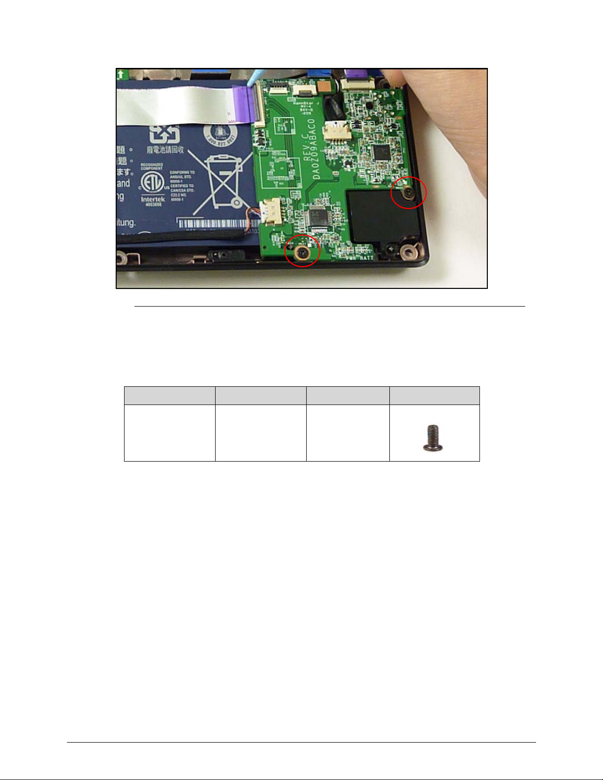
3-17
Figure 3-2. Audio Board Screws Removal
6. Remove the screw(s).
7. Remove the Audio Board.
ID Size Quantity Screw Type
M2.0 x 3.0 2
Page 100
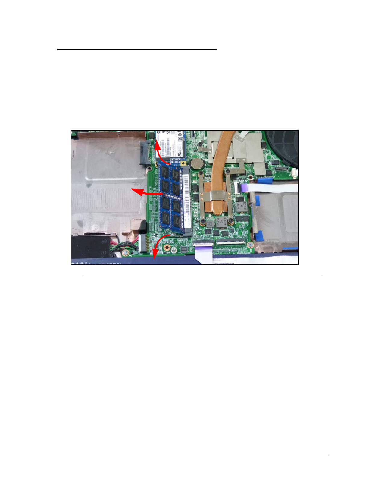
3-18
DIMM Removal 0
Prerequisite:
Top Cover Removal
1. Locate DIMM module on mainboard.
2. Push module clips outwards.
3. Remove DIMM module from mainboard connector.
Figure 3-1. DIMM Removal
 Loading...