

Page 1

Acer Altos G900
User’s guide
Page 2

Copyright © 2003 Acer Incorporated
All Rights Reserved.
Acer Altos G900
User’s guide
January 2003
Changes may be made periodically to the information in this publication without obligation
to notify any person of such revision or changes. Such changes will be incorporated in new
editions of this manual or supplementary documents and publications. This company makes
no representations or warranties, either expressed or implied, with respect to the contents
hereof and specifically disclaims the implied warranties of merchantability or fitness for a
particular purpose.
Record the model number, serial number, purchase date, and place of purchase information in
the space provided below. The serial number and model number are recorded on the label
affixed to your server. All correspondense concerning your unit should include the serial
number, model number, and purchase information.
No part of this publication may be reproduced, stored in a retrieval system, or transmitted, in
any form or by any means, electronic, mechanical, photocopy, recording, or otherwise,
without the prior written permission of Acer Incorporated.
Model Number : _________________________________
Serial Number: ___________________________________
Purchase Date: ___________________________________
Place of Purchase: ________________________________
Acer and the Acer logo are registered trademarks of Acer Inc. Other company’s product
names or trademarks are used herein for identification purposes only and belong to their
respective companies.
Page 3

iii
Notices
FCC notice
This device has been tested and found to comply with the limits for a Class A
digital device pursuant to Part 15 of the FCC Rules. These limits are designed to
provide reasonable protection against harmful interference in a residential
installation. This device generates, uses, and can radiate radio frequency
energy, and if not installed and used in accordance with the instructions, may
cause harmful interference to radio communications.
However, there is no guarantee that interference will not occur in a particular
installation. If this device does cause harmful interference to radio or television
reception, which can be determined by turning the device off and on, the user
is encouraged to try to correct the interference by one or more of the following
measures:
• Reorient or relocate the receiving antenna
• Increase the separation between the device and receiver
• Connect the device into an outlet on a circuit different from that to which
the receiver is connected
• Consult the dealer or an experienced radio/television technician for help
Notice: Shield cables
All connections to other computing devices must be made using shielded cables
to maintain compliance with FCC regulations.
Notice: Peripheral devices
Only peripherals (input/output devices, terminals, printers, etc.) certified to
comply with the Class A limits may be attached to this equipment. Operation
with noncertified peripherals is likely to result in interference to radio and TV
reception.
Caution! Changes or modifications not expressly approved by
the manufacturer could void the user’s authority, which is granted
by the Federal Communications Commission, to operate this
computer.
Page 4

iv
Use conditions
This part complies with Part 15 of the FCC Rules. Operation is subject to the
following two conditions: (1) this device may not cause harmful interference,
and (2) this device must accept any interference received, including interference
that may cause undesired operation.
Notice: Canadian users
This Class A digital apparatus meets all requirements of the Canadian
Interference-Causing Equipment Regulations.
Remarque à l’intention des utilisateurs canadiens
Cet appareil numérique de la classe A respected toutes les exigences du
Règlement sur le matériel brouilleur du Canada
.
Laser compliance statement
The CD-ROM drive in this computer is a laser product. The CD-ROM drive’s
classification label (shown below) is located on the drive.
CLASS 1 LASER PRODUCT
CAUTION: INVISIBLE LASER RADIATION WHEN OPEN. AVOID EXPOSURE TO
BEAM.
Page 5

Important safety information
Only a technically qualified person shall access, integrate, configure, and service
this product.
Intended application uses
This product was evaluated as an Information Technology Equipment (ITE),
which may be installed in offices, schools, computer rooms, and similar
commercial type locations. The suitability of this product for other Product
Categories and Environments (such as medical, industrial, alarm systems, and
test equipment), other than as an ITE application, may require further
evaluation.
Checking the power cords
Warning! To avoid electrical shock, do not attempt to
modify or use the supplied AC power cord(s), if they are
not the exact type required.
If a power cord(s) supplied is not compatible with the AC wall outlet in your
region, get one that meets the following criteria:
• The power cord must be properly rated for the AC voltage in your region.
• The power cord plug cap must have an electrical current rating that is at
least 125% of the electrical current rating of the product.
• The power cord plug cap that plugs into the wall socket-outlet must have a
grounding-type male plug designed for use in your region.
• The power cord must have safety certifications for your region, and shall
be marked with the certification markings.
• The power cord plug cap that plugs into the AC receptacle on the power
supply must be an IEC 320, sheet C13, type female connector.
• In Europe, the power cord must be less than 4.5 meters (14.76 feet) long,
and it must be flexible <HAR> (harmonized) or VDE certified cordage to
comply with the chassis' safety certifications.
• The power supply cord(s) is the main disconnect device to AC power. The
socket outlet(s) shall be near the equipment and shall be readily accessible
for disconnection.
v
Page 6

vi
Multiple power cords
Warning! To avoid electrical shock, disconnect all AC power cords before
accessing inside the system.
Earth grounded socket-outlets
Warning! To avoid electrical shock, the system power cord(s) must be plugged
into socket-outlet(s) that is provided with a suitable earth ground.
Precautionary reminders
• Over current protection
The system is designed to operate on a 20A AC voltage source that is
provided with 20A over current protection. If the AC source for the rack
exceeds 20A over current protection, each system must be provided with
20A or less over current supplemental protection. The supplementary over
current protection must have the appropriate regional safety certifications
for the over current application.
• Power supply modules
Power supply modules have double-pole/neutral fusing.
• Ventilation considerations
The equipment rack must provide sufficient airflow to the front of the
system to maintain proper cooling. The rack selected and the ventilation
provided must be suitable to the environment in which the system will be
used.
•Fans
To avoid injury do not touch moving fan blades.
• Cooling and airflow
For proper cooling and airflow, always install all access covers before
turning on the system. Operating the system for longer than five minutes
without the covers in place can cause overheating and damage to system
components.
• Temperature limits
The operating temperature of the system, when installed in the rack, must
not go below 10°C (50°F) or rise above 35°C (95°F). Extreme fluctuations in
temperature may cause a variety of problems in system, and safety limits
may be broken.
• Lifting and Moving
Do not attempt to lift or move the server by the handles on the power
supplies.
Page 7

Equipment rack precautions
Follow the rack manufacturer's safety and installation instructions for proper
rack installation.
The following additional rack safety installation measures shall be considered:
• Anchor the equipment rack
The equipment rack must be anchored to an unmovable suitable support
to prevent the rack from falling over when one or more systems are fully
extended out of the rack assembly. You must also consider the weight of
any other devices installed in the rack assembly. The equipment rack must
be installed according to the manufacturer's instructions.
• Main AC power disconnect
You are responsible for installing an AC power disconnect for the entire
rack unit. This main disconnect must be readily accessible, and it must be
labeled as controlling power to the entire unit, not just to the system(s).
• Grounding the rack installation
To avoid the potential for an electrical shock hazard, the rack assembly
itself must be suitably earth grounded, according to your local regional
electrical codes. This typically will require the rack to have its own separate
earth ground. We recommend you consult your local approved electrician.
vii
Page 8

viii
Important safety instructions
Read these instructions carefully. Save these instructions for future reference.
1 Follow all warnings and instructions marked on the product.
2 Unplug this product from the wall outlet before cleaning. Do not use
liquid cleaners or aerosol cleaners. Use a damp cloth for cleaning.
3 Do not use this product near water.
4 Do not place this product on an unstable cart, stand, or table. The product
may fall, causing serious damage to the product.
5 Slots and openings in the cabinet and the back or bottom are provided for
ventilation; to ensure reliable operation of the product and to protect it
from overheating, these openings must not be blocked or covered. The
openings should never be blocked by placing the product on a bed, sofa,
rug, or other similar surface. This product should never be placed near or
over a radiator or heat register, or in a built-in installation unless proper
ventilation is provided.
6 This product should be operated from the type of power indicated on the
marking label. If you are not sure of the type of power available, consult
your dealer or local power company.
7 Do not allow anything to rest on the power cord. Do not locate this
product where persons will walk on the cord.
8 If an extension cord is used with this product, make sure that the total
ampere rating of the equipment plugged into the extension cord does not
exceed the extension cord ampere rating. Also, make sure that the total
rating of all products plugged into the wall outlet does not exceed the fuse
rating.
9 Never push objects of any kind into this product through cabinet slots as
they may touch dangerous voltage points or short out parts that could
result in a fire or electric shock. Never spill liquid of any kind on the
product.
10 Do not attempt to service this product yourself, as opening or removing
covers may expose you to dangerous voltage points or other risks. Refer all
servicing to qualified service personnel.
11 Unplug this product from the wall outlet and refer servicing to qualified
service personnel under the following conditions:
a When the power cord or plug is damaged or frayed
b If liquid has been spilled into the product
c If the product has been exposed to rain or water
Page 9

d If the product does not operate normally when the operating
instructions are followed. Adjust only those controls that are covered
by the operating instructions since improper adjustment of other
controls may result in damage and will often require extensive work
by a qualified technician to restore the product to normal condition.
e If the product has been dropped or the cabinet has been damaged
f If the product exhibits a distinct change in performance, indicating a
need for service.
12 Replace the battery with the same type as the product's battery we
recommend. Use of another battery may present a risk of fire or explosion.
Refer battery replacement to a qualified serviceman.
13 Warning! Batteries may explode if not handled properly. Do not
disassemble or dispose of them in fire. Keep them away from children and
dispose of used batteries promptly. Dispose of used batteries according to
manufacturer's instructions.
14 Use only the proper type of power supply cord set (provided in your
accessories box) for this unit. It should be a detachable type: UL listed/CSA
certified, type SPT-2, rated 7A 125V minimum, VDE approved or its
equivalent. Maximum length is 15 feet (4.6 meters).
ix
Page 10

x
Page 11

Notices iii
FCC notice iii
Laser compliance statement iv
Important safety information v
Intended application uses v
Checking the power cords v
Precautionary reminders vi
Equipment rack precautions vii
Important safety instructions viii
1 System tour 1
Features overview 3
Altos G900 physical specifications 4
External and internal structure 5
Access covers 5
Main chassis components 6
Electronics bay components 7
Front control panel 8
Rear panel 10
Peripheral device bay 12
Server board set features 13
Mainboard layout 13
System cables 19
System features 22
Processors 22
Memory 22
SCSI controller 22
Onboard video 23
Network interface controllers 23
Hot-swap hard drive bays 24
Power supply 25
System fan 25
ACPI 26
Contents
2 System setup 27
Getting started 29
Checking for damage to the packaging 29
Selecting a site 29
Checking the package contents 30
Setting up your system 32
Setup reminders 32
Pre-setup safety steps 32
Page 12

xii
Hardware setup 33
Turning on the server and running the Power-On
Self Test (POST) 34
Software setup 36
Network teaming features 37
3 Hardware configuration 39
Installation precautions 41
ESD precautions 41
Preinstallation instructions 42
Post-installation instructions 42
Tools and supplies needed 43
System access panels 44
Before removing the access panels 44
Rear access panel 44
Front access panel 45
Front subchassis and rear
electronics bay 47
Opening the front subchassis and rear
electronics bay 47
Removing the front subchassis and rear
electronics bay 48
Closing the front subchassis and rear
electronics bay 50
Accessing the system boards 51
Access cover to the system boards 51
Memory board 52
53
53
53
Processor board 54
Mainboard 55
Memory 60
DIMM sequence 60
Processors 63
Processor sequence 63
PCI add-in boards 67
PCI add-in board locations 67
Operating system support for hot-plug
add-in boards 68
Checking the status indicators for a hot-plug
add-in board 68
Installing and removing a hot-plug PCI
Page 13

add-in board 69
Installing and removing a PCI add-in board in
a non-hot-plug slot 72
Hot-swap SCSI drives 75
Checking a hot-swap SCSI drive status indicator 75
Installing and removing a hot-swap drive
in a carrier 76
Removing and installing hot-swap disk drives 78
DC power supplies 81
Checking the power supply LED status indicators 81
Removing and installing a power supply module 82
Cooling system fans 85
Checking a fan status indicator 85
Removing and installing a fan module 86
Backup battery 87
Replacing the battery 87
Front panel board 89
Installing the front panel board 89
Diskette drive 91
Replacing the diskette drive 91
5.25-inch peripheral drives 94
Preliminary considerations 94
Removing and installing a 5.25-inch
peripheral drive 95
Hot-swap drive bays 98
Removing and installing a hot-swap drive bay 98
Power distribution board 101
Replacing the power distribution board 101
Fan distribution board 103
Replacing the fan distribution board 103
Foam fan baffle 105
Removing and installing the foam fan baffle 105
Hot-plug indicator board 107
Replacing the hot-plug indicator board 107
4 BIOS setup 109
BIOS setup 111
Recording BIOS settings 111
Clearing CMOS memory 111
Using BIOS setup 112
Main 114
Primary IDE Master/Slave 116
Processor Settings 118
Page 14

xiv
Advanced 119
Memory Configuration 121
PCI Configuration 122
I/O Device Configuration 129
Advanced Chipset Control 131
Security 132
Server 136
System Management 138
Console Redirection 139
Boot 140
Exit 141
Appendix A: System rack installation 143
System rack installation 145
Rack-mount kit contents 145
Tools and supplies needed 146
Equipment rack precautions 146
Rack conversion procedures 148
Removing the bottom panel 148
Removing the left panel 149
Removing the original tower bezel 150
Removing the feet 151
Installing the rack bezel 152
Installing the bushings on the chassis 153
Installing the handles and rails 154
Appendix B: System management 159
Software and utilities 161
Integrated hardware system management 162
Baseboard management controller 162
Field replaceable units and sensor data records 163
System event log 163
Platform event management 164
Emergency management port 165
System Setup Utility 166
Creating SSU diskettes 166
Running the SSU 167
Working with the GUI 168
Customizing the SSU interface 168
Setting boot device priority 169
Setting passwords and security options 169
Viewing the system event log 171
Viewing FRU information 172
Page 15

Viewing Sensor Data Records 173
Updating system firmware and BIOS 174
Saving and restoring the system configuration 174
Alerting for platform events 175
Managing the server remotely 179
Exiting the SSU 182
FRU/SDR load utility 183
When to run the FRU/SDR load utility 183
Running the FRU/SDR load utility 183
SCSISelect 186
Running SCSISelect 186
Software updates 187
Software update packages 188
Individual updates 189
Appendix C: Equipment log and configuration worksheets
193
Equipment log 195
Calculating power consumption 196
Calculating DC power usage 196
Calculating the total combined power used
by the system 198
xv
Appendix D: Troubleshooting 199
Troubleshooting 201
Resetting the system 201
Initial system startup 201
Running new application software 202
After the system has been running correctly 203
Monitoring POST 203
Verifying proper operation of key system lights 204
Confirming loading of an operating system 204
Frequently asked questions (FAQs) 205
Appendix E: Codes and error messages 211
Standard BIOS post codes 213
Recovery BIOS POST codes 219
BMC beep codes 221
POST error messages and codes 222
Index 227
Page 16

xvi
Page 17

1 System tour
Page 18

This chapter gives you a tour of the system’s
internal and external components, as well as
a discussion of its many features.
Page 19

Features overview
The Acer Altos G900 four-way performance server model utilizes a PCI
bus based mainboard built on an ATX form factor. It supports up to
four processors from the Intel
For expandability, the mainboard supports eight full length PCI slots
(4 PCI-X hot plug, 2 PCI-X non-hot plug, 2 PCI non-hot plug). An
impressive 24 GB maximum system memory is achieved through 12
DIMM sockets utilizing DDR-266 (Double Data Rate) modules.
Media drives include one 3.5-inch floppy drive, a CD-ROM drive, plus
two 5.25-inch peripheral bays. The system also supports up to ten
1-inch hot-swap Ultra 320 SCSI hard drives providing an additional
1460 GB of storage space.
For connectivity, the mainboard provides two external USB (Universal
Serial Bus) ports and one internal header providing one additional USB
port, PS/2 interface for both mouse and keyboard, one VGA/monitor
port, one external serial port and one internal serial port header, one
parallel port with Extended Capabilities Port (ECP)/Enhanced Parallel
Port (EPP) support, and for networking, two NIC ports (RJ-45).
Power supply is provided by the three hot-swap power supply modules
in a 2+1 redundant configuration (third module optional).
®
Xeon™ processor family.
3
In terms of serviceability, the system features front access to hot-swap
hard disk drives, rear access to hot-swap power supplies, and side
access to hot-plug PCI boards and hot-swap fans. Serviceable items are
color coded throughout and detailed configuration labels are located
on the system’s side panel. Fault indicators and system UID (Unit ID)
light are also available.
Manageability features include compliance to both IPMI 1.5 and WfM
2.0 standard, extensive system sensors and monitoring, as well as
function for remote management and diagnostics via the serial or LAN
port. External chassis management is done via ICMB.
Page 20

4
1 System tour
Altos G900 physical specifications
Specification Rack-mount orientation Tower orientation
Height 12.25 inches (311 mm) (7U) 18.09 inches (459 mm)
Width Fits 19-inch rack 12.24 inches (311 mm)
Depth 25.25 inches (641 mm) 25.25 inches (641 mm)
Weight
Minimum
configuration
Maximum
configuration
90 pounds (41 kg)
119 pounds (57 kg)
96 pounds (44 kg)
125 pounds (57 kg)
Required front
clearance
Required rear
clearance
Required side
clearance
Power
requirements
Voltage (110)
Voltage (220)
Frequency
Note: Amperage values indicated on this section is based on
total system power, with two or three power supply modules
installed. For detailed information on calculating power
consumption for specific server configurations, see page 196.
3 inches (76 mm),
inlet airflow <35 °C (95 °F)
4.5 inches (114 mm),
no airflow restriction
0 inch (0 mm) 0 inch (0 mm)
90 Vrms min, 132 Vrms
max, 9 Arms
180 Vrms min, 264 Vrms
max, 4.5 Arms
47 Hz min, 63 Hz max
12 inches (305 mm)
9 inches (229 mm)
90 Vrms min, 132 Vrms
max, 9 Arms
180 Vrms min, 264 Vrms
max, 4.5 Arms
47 Hz min, 63 Hz max
Page 21
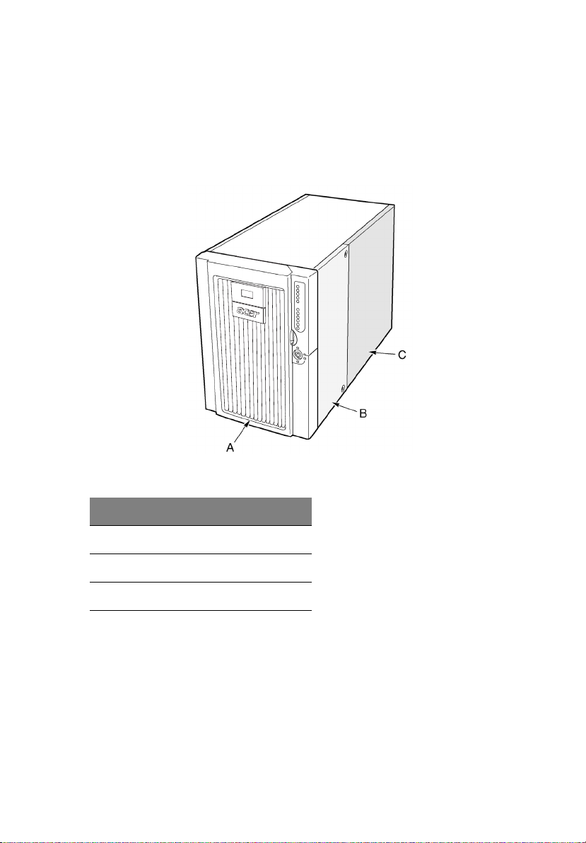
External and internal structure
Access covers
The figure below shows the system’s access panels
5
Label Description
A Bezel
B Front access panel
C Rear access panel
Figure 1 - Access covers
Page 22
6
1 System tour
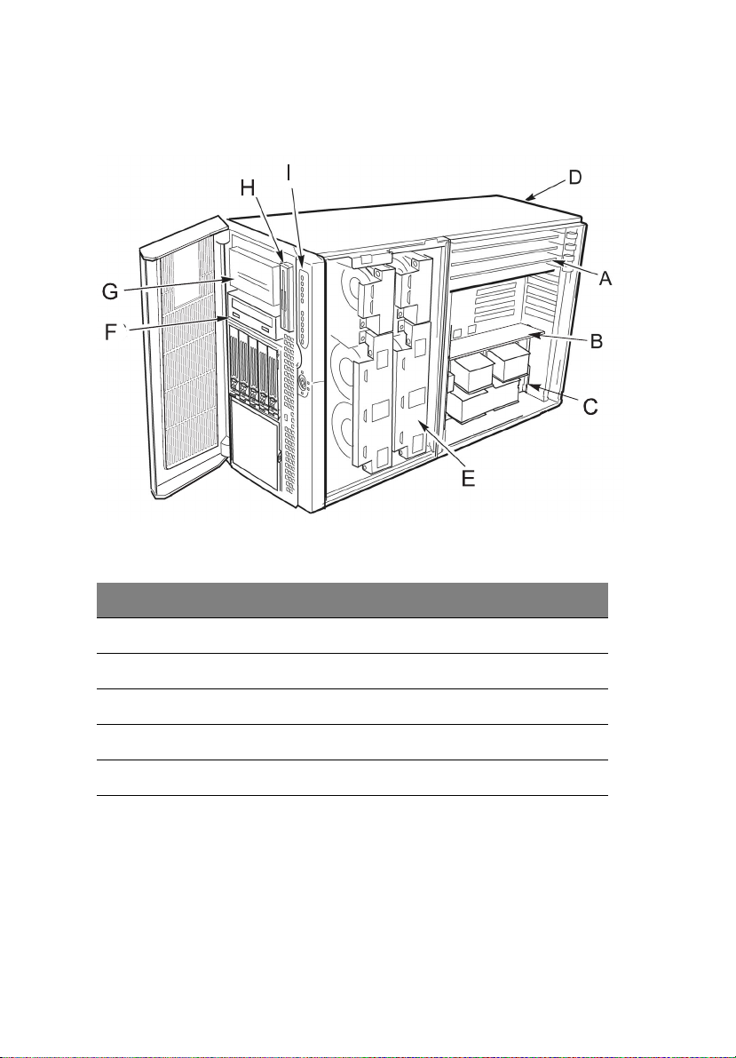
Main chassis components
The figure below shows the chassis with the access panels removed.
Figure 2 - Main chassis components
Label Description Label Description
A Hot-plug PCI add-in cards F CD-ROM drive
B Memory board G 5.25-inch peripheral bay
C Electronics bay H 3.5-inch diskette
D Power supply bay I Front control panel
EFan bay
Page 23
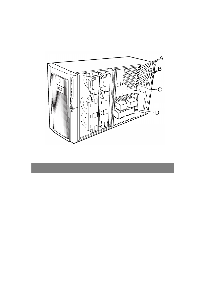
Electronics bay components
The figure below shows the electronics bay with the access cover and
memory board removed.
Figure 3 - Electronics bay components
7
Label Description Label Description
A Hot-plug PCI slots C Mainboard
B Non-hot-plug PCI slots D Processor board
Page 24
8
1 System tour
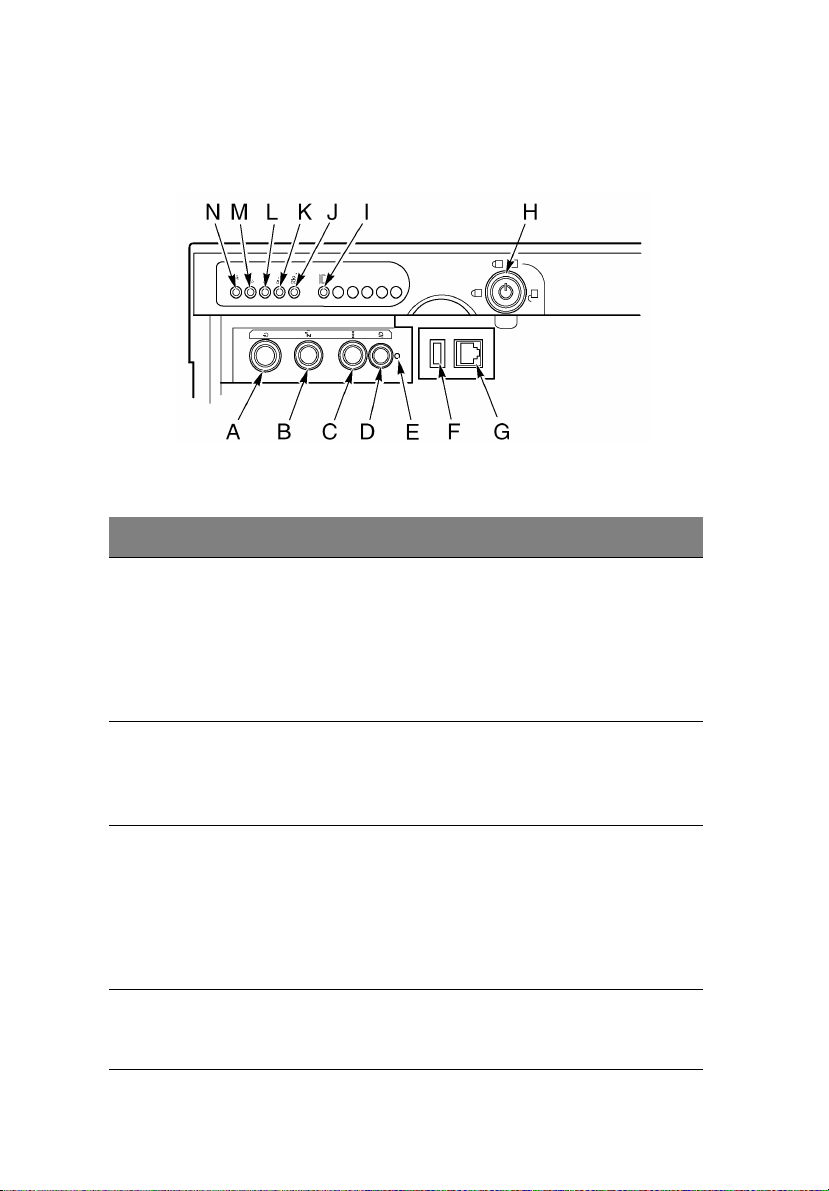
Front control panel
The figure below describes the features of the front control panel.
Figure 4 - Front control panel
Label Description Operation
A Power button To turn power on, press the power button
momentarily. If the system is in sleep state,
pressing the power button momentarily brings
the system out of the sleep state.
To turn power off, press and hold the power
button for more than four seconds. This
overrides ACPI mode.
B Sleep button To put a system supporting ACPI into sleep
mode (S1), press the sleep button momentarily.
To wake a system from sleep mode, press the
sleep button momentarily.
C Reset button To reset the system, press the reset button
momentarily.
To clear CMOS, press and hold the reset button
for at least four seconds, and then press the
power button. Release both the reset and
power buttons at the same time. The system
will power on and the CMOS will be reset.
D Chassis ID
button
Illuminates LEDs on both the front and rear of
the chassis, simplifying identification of the
chassis in a rack from the rear.
Page 25

Label Description Operation
E NMI switch Causes a non-maskable interrupt. Located
behind the bezel door.
F USB connector USB port 3. Located behind the bezel door.
9
G Serial port
connector
H Lock Locks the bezel and front access cover.
I Chassis ID LED Blue indicates chassis ID is active.
J LAN2 LED Green indicates LAN2 activity.
K LAN1 LED Green indicates LAN1 activity.
L Hard drive
activity LED
M Fault LED Red indicates any system fault condition.
N Main power
LED
Serial port B. Located behind the bezel door.
Green indicates system hard drive activity.
Solid green indicates the presence of DC power
in the server.
Flashing green indicates that the system is in
ACPI sleep mode.
Page 26
10
Rear panel
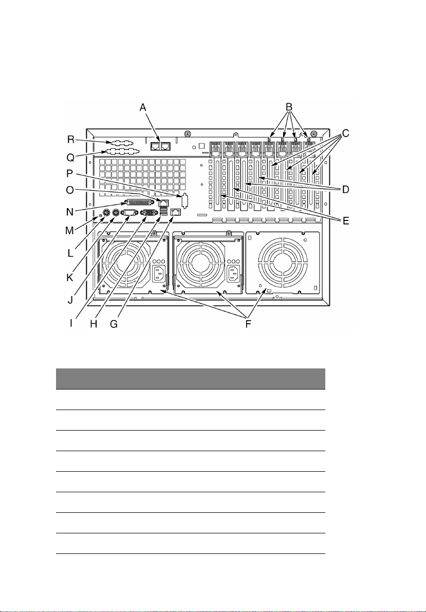
The figure below describes the features of the rear panel.
1 System tour
Figure 5 - Rear panel
Label Description
A Optional ICMB ports 1 (left) and 2 (right)
B Hot-plug PCI LEDs
C Hot-plug 64-bit, 100 MHz PCI-X add-in card slots
D Non-hot-plug 64-bit, 100 MHz PCI-X add-in card slots
E Non-hot-plug 32-bit, 33 MHz PCI add-in card slots
F Power supply bays
G LAN2 Gbit RJ-45 connector
H USB ports 0 (upper) and 1 (lower)
Page 27

Label Description
IVideo connector
J Serial port A
K PS/2-compatible mouse port
L PS/2-compatible keyboard port
M Chassis ID LED
N IEEE 1284 Enhanced Parallel Port
O LAN1 100/10 RJ-45 connector
P Knockout for optional serial port B
Q Knockout for optional SCSI connector
R Knockout for optional VHDCI SCSI connector
11
Page 28
12
1 System tour
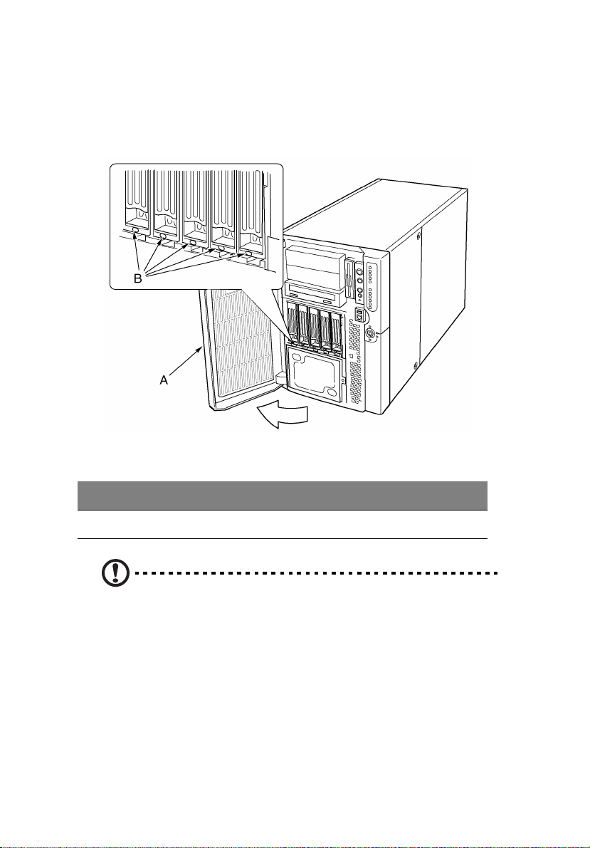
Peripheral device bay
Opening the right bezel door provides access to the peripheral bay.
The peripheral bay consists of four bays for removable media:
Figure 6 - Peripheral device bay
Label Description Label Description
A Front bezel door B LED status indicators
Caution! It is not recommended to install a hard disk drive in the
5.25-inch bay, because of potential cooling and electromagnetic
interference (EMI) constraints.
Page 29
Server board set features
The server board set for Altos G900 consists of a mainboard, memory
board, and processor board.
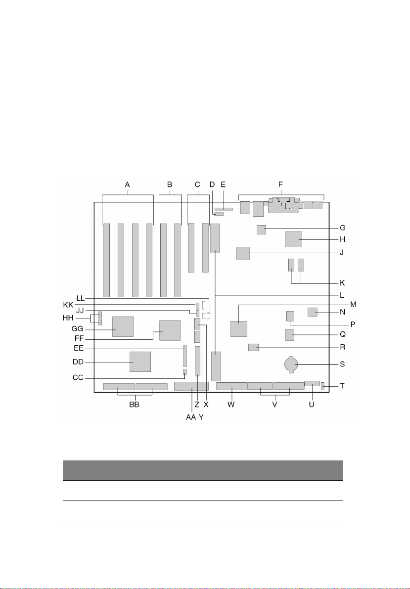
Mainboard layout
Below illustration identifies the connectors and major components on
the Altos G900 mainboard.
13
Figure 7 - Mainboard layout
Label Description
A 64-bit, 100-MHz, hot-plug PCI-X slots
B 64-bit, 100-MHz, non-hot-plug PCI-X slots
Page 30

14
Label Description
C 32 bit, 33-MHz, non-hot-plug PCI slots
D Intelligent Chassis Management Bus (ICMB) connector (P24)
E Hot-plug indicator board (HPIB) connector (P23)
F Back panel I/O connectors
1 System tour
G
®
Intel
82550 Ethernet controller
H ATI Rage XL 2D/3D graphics accelerator
J
®
Intel
82544 Ethernet controller
K Video RAM (VRAM) (4 MB total)
L Processor board connectors (P21 and P22)
M ServerWorks south bridge controller (CSB5)
N BMC component
P BIOS Flash component
Q PC87417 Super I/O controller
R BMC Flash component
S Battery
T Reserved
U power control connector (P35)
V power connector (P32)
W Floppy disk drive connector (P25)
X Serial port B connector (P17)
Y USB port 3 header (P18)
Z Front panel header (P19)
Page 31

Label Description
AA IDE connector (P13)
BB SCSI LVD connectors (P4 and P7)
CC Intelligent Platform Management Bus (IPMB) connector (P12)
DD Adaptec 7902 SCSI controller
EE Fan connector (P11)
FF ServerWorks PCI-X bus bridge controller (CIOB30)
GG ServerWorks PCI-X bus bridge controller (CIOB30)
HH RAID LED connectors (P1 and P2)
JJ Hot-swap backplane (HSBP) connector (P16)
KK Secondary HSBP connector (P15)
LL Jumpers
Mainboard jumpers
15
Jumpers on the mainboard are organized into three groups:
• Boot block jumpers (JP3)
• Main jumpers (JP4, JP5, and JP6)
• Serial port B jumpers (JP25).
Page 32

16
1 System tour
The figure below identifies the jumper blocks and pin numbers. The
function of each pair of pins is described in the sections that follow.
Figure 8 - Mainboard jumpers
Boot block jumpers
The boot block jumpers are used when updating the BIOS or BMC
firmware in the unusual event that the boot block area needs to be
updated. These jumpers are not used for routine firmware updates.
Use the boot block jumpers only when the instructions with a firmware
update specifically say to do so. When you do need to enable either of
these features, use one of the spares from JP4 pins 1 and 2 or JP25 pins
7 and 8. The table below identifies the function of each pin pair on
JP3.
Page 33

17
Jumper
block
JP3 1-8 Reserved.
Pins Jumper name - effect when shorted
9-10 BMC Boot Block Write Enable - Allows the BMC boot
block to be overwritten when updating the BMC
firmware.
11-12 BIOS Boot Block Write Enable - Allows the BIOS boot
block to be overwritten when updating the BIOS.
Main jumpers
Below table identifies the function of each pin pair on the main
jumper blocks (JP4, JP5, and JP6). The FRB3 Timer Disable jumper and
the BMC Force Update jumper are special purpose jumpers that you
should use only when instructed to do so. When you do need to
enable any of these features, use one of the spares from JP4 pins 1 and
2 or JP25 pins 7 and 8.
Jumper
block
Pin Jumper name - effect when shorted
1-2 Spare
3-4 BIOS Recovery - System will attempt to recover the
BIOS at the next boot.
5-6 Reserved
JP4
JP5 1-2 FRB3 Timer Disable - Disables fault resilient boot timer
JP6 1-2 BMC Force Update - Lets a system with corrupted BMC
7-8 Reserved
9-10 Password Clear - User and administrator passwords
are cleared at the next boot.
11-12 CMOS Clear - CMOS settings are cleared at the next
boot.
3.
firmware boot for an update.
Page 34

18
1 System tour
Serial port B jumpers
The table identifies the function of each pin pair on the serial port B
jumper block (JP25). By default, the serial port B connector is an RJ-45,
which has only eight pins and doesn't provide separate DCD and DSR
signals. The serial port B jumpers let you configure the DSR and DCD
signals passed from the port connector to the inputs of the UART. The
default configuration has jumpers installed on pins 1 and 2 and on pins
3 and 4.
Caution! Never install jumpers on pins 3 and 4 and on pins 5 and
6 at the same time. This would cause both the DCD and DSR
signals from the connector to drive the DCD input on the UART,
resulting in signal contention.
Jumper
block
JP25 1-2 DSR to DSR - DSR from connector is passed to DSR
Pin Jumper name - effect when shorted
input on UART (RJ-45 & DB9).
3-4 DSR to DCD - DSR from connector is passed to DCD
input on UART (RJ-45 only).
5-6 DCD to DCD - DCD from connector is passed to DCD
input on UART (DB9 only).
7-8 Spare.
Page 35

19
System cables
This section shows the correct routing of cables from the mainboard to
the front subchassis
Caution! To avoid possible damage to the cables or internal
components, the cables must be routed as shown in the following
illustrations.
Figure 9 shows the routing of cables from the mainboard to the front
subchassis components.
Figure 9 - Cables to the subchassis
Label Description Label Description
A Fan distribution board cable D IDE peripheral cable
B Front panel board cable E Diskette drive cable
Page 36

20
Label Description Label Description
C SCSI hard drive cable F Serial port B cables
1 System tour
Figure 10 shows the routing of ribbon cables through the cable clamp.
Additional cables are routed behind these ribbon cables as shown in
Figure 11.
Figure 10 - Front cables in the cable clamp
Label Description Label Description
A Diskette drive cable C Front panel board cable
B IDE peripheral cable D Cable clamp
Page 37

Finally, Figure 11 shows the routing of the cables at the back of the
cable clamp, behind the ribbon cables.
21
Figure 11 - Rear cables in the cable clamp
Label Description
A Front panel cable
B Serial port B cable
C Hot-swap back plane cable
DCable clamp
E Fan distribution board cable
Page 38

22
1 System tour
System features
The Altos G900 is a powerful server system loaded with a host of new
and innovative features. The system offers a new standard for flexible
productivity ideal for general business applications, email, web service,
file clustering and print services.
Processors
The Altos G900 server accommodates one to four processors from the
®
Xeon™ processor family.
Intel
Memory
The memory board contains twelve 184-pin DIMM slots each
supporting 72-bit ECC (64-bit main memory plus ECC) registered PC-266
Double Data Rate (DDR) DIMMs. Memory is partitioned in three banks.
You may install a minimum of 512 MB (128 MB x 4) or as much as
24 GB.
• Minimum configuration: Four 128-MB DIMMs, for a total of
512 MB
• Maximum configuration: Twelve 2-GB stacked DIMMs for a total
of 24 GB
The controller automatically detects, sizes, and initializes the memory
array, depending on the type, size, and speed of the installed DIMMs,
and reports memory size and allocation to the server via configuration
registers.
SCSI controller
The mainboard includes an embedded Adaptec® 7902 SCSI controller,
which contains two independent SCSI channels. You can disable the
SCSI controller in BIOS setup. Both channels support 16-bit SE or LVD
SCSI operations at the following speeds:
• Ultra320 (320/MB/sec)
• Ultra160 (160 MB/sec)
• Ultra2 (80 MB/sec)
• Ultra Wide SE (40 MB/sec)
Page 39

23
The mainboard provides active terminators, termination voltage,
resettable fuses, and protection diodes for both SCSI channels. You can
disable the onboard terminators in BIOS setup.
Onboard video
The mainboard incorporates an ATI RAGE XL PCI graphics accelerator
with 4 MB of video SDRAM that supports all standard IBM VGA modes.
The embedded SVGA video subsystem supports:
• Pixel resolutions up to 1600 x 1200 under 2D and 1024 x 768 under
3D
• CRT and LCD monitors up to 100 Hz vertical refresh rate
The mainboard supports disabling of the onboard video through BIOS
setup or when a plug-in video card is installed in any of the PCI slots.
Network interface controllers
Note: To ensure EMC product regulation compliance, the system
must be used with shielded LAN cables.
The mainboard includes two network interface controllers (NICs):
•Intel
®
82550 NIC that supports 10Base-T and 100Base-TX networks
The 82550 controller supports the following features:
• 32-bit PCI, CardBus master interface
• Integrated IEEE 802.3 10Base-T and 100Base-TX compatible
PHY
• IEEE 820.3u auto-negotiation support
• Chained memory structure similar to the 82559, 82558, 82557
and 82596
• Full duplex support at both 10 Mbps and 100 Mbps operation
• Low power +3.3 V device
• IP checksum off-loading
NIC 1 can be used as both a network interface and server
management interface.
Page 40

24
1 System tour
•Intel
®
82544 NIC that supports 10Base-T, 100Base-TX networks,
and 1000BASE-T networks
The 82544 controller supports the following features:
• Direct 32/64-bit, 33/66-MHz interface to the PCI bus
• Integrated IEEE 802.3 1000BASE-T, 100BASE-TX, and 10BASE-T
• Integrated third-generation MAC and proven IEEE 803.3ab
compatible PHY
• Full duplex support for 10-Mbps, 100-Mbps, and 1000 Mpbs
operation
• Descriptor ring management architecture optimized to deliver
both high performance and PCI/PCI-X bus efficiency
• Low power +3.3 V device
• IP and TCP/UDP checksum off-loading
Hot-swap hard drive bays
The server comes with one hot-swap hard drive cage installed. A
second bay is available as an accessory. The hard drive bays each
support up to five 3.5-inch by 1.0-inch Ultra320 SCSI hard drives. The
hard drive bays also support SCSI hard drive technologies, such as
Ultra160 and Ultra2, that are slower than the Ultra320 SCSI technology.
®
Each hard drive is connected to an Adaptec
backplane. The backplane provides 80-pin SCA-2 connectors for each
hard drive and accepts 15,000 RPM and slower SCSI hard drives that
consume up to 20 watts of power.
Ultra320 SCSI hot-swap
Opening the bezel door provides access to the hard drives. To allow
hot swapping, each hard drive mounts in a hard drive carrier. When a
hard drive is removed from the system, both the carrier and the hard
drive are removed.
Caution! Because all hard drives have different cooling, power,
and vibration characteristics, specific hard drive types has been
validated to be compatible with the Altos G900 system.
Page 41

25
Power supply
The power supply bay comes with two 600-W power supply modules
and can accommodate a third module for redundancy. The modules
connect through the power distribution board (PDB) and auto-sense
input voltage. The power redundant (2+1) configuration allows you to
hot-swap a failed power supply without interrupting normal system
operation.
Warning! The power supply in this product contains no
user-serviceable parts. There may be more than one power
supply in this product. Refer servicing only to qualified
personnel.
System fan
Caution! All access covers must be on the system for proper
cooling.
To ensure that all components remain within specification under all
system environmental conditions, do not exceed five minutes for hot
swapping of fans or power supplies.
The server comes with four fan modules. Air enters through the bezel,
passes through the fan bay and electronics bay, and exhausts through
the rear of the chassis. The power supply modules and hot-swap hard
drive bays also come with their own fans which draw air through those
components and through the peripheral bays.
Under normal system conditions, the fans run at a slower, quieter
speed. If a fan failure is sensed, a fan is not detected, or ambient
temperature exceeds a certain limit, the fan speed is set to high.
LEDs indicate if individual fans are inoperative or not present. Under
the same fan failure conditions, the general system fault LED on the
front panel is lit.
Page 42

26
1 System tour
ACPI
The server supports the Advanced Configuration and Power Interface
(ACPI) standard as defined by the ACPI 1.0b and PC97 specifications.
An ACPI-aware operating system can put the system into a state where
the hard drives spin down, the system fans stop, and all processing is
halted. However, the power supply will still be on and the processors
will still be dissipating some power, so the power supply fans will still
run.
The server supports sleep states s0, s1, s4, and s5:
• s0: Normal running state.
• s1: Processor sleep state - No context will be lost in this state and
the processor caches will maintain coherency.
• s4: Hibernate or Save to Disk - The memory and machine state are
saved to disk. Pressing the power button or other wakeup event
will restore the system state from the disk and resume normal
operation. This assumes that no hardware changes have been
made to the system while it was off.
• s5: Soft off - Only the RTC section of the CSB and the BMC are
running in this state. No context is saved by the operating system
or hardware.
Caution! The system is off only when the AC power cord is
disconnected.
Page 43

2 System setup
Page 44

This chapter describes the system setup procedures
— both for hardware and software aspects.
Page 45

Getting started
Checking for damage to the packaging
Inspect the packaging container for evidence of mishandling during
transit. If the packaging container is damaged, photograph it for
reference. Save the packaging container and packing materials in the
event you need to package the server for reshipment.
Selecting a site
Before unpacking and installing the system, select a suitable site for
the system for maximum efficiency. Consider the following factors
when choosing a site for the system:
• Near a properly grounded, three-pronged power outlet
Note:
In the United States and Canada: a NEMA 6-15R outlet for 100120 V and for 200-240 V.
In other geographic areas: a properly grounded outlet in
accordance with the local electrical authorities and electrical code
of the region.
29
• Clean and dust-free
• Stable surface free from vibration
• Well-ventilated and away from sources of heat, with the
ventilation openings on the server kept free of obstructions
• Secluded from strong electromagnetic fields and noise caused by
electrical devices such as elevators, copy machines, air
conditioners, large fans, large electric motors, radio and TV
transmitters, and high-frequency security devices.
• Maximum ambient air temperature should not exceed 35°C
(95°F).
• Access space provided so the server power cords can be unplugged
from the power supply or the wall outlet; this is the only way to
remove AC power from the server.
Page 46

30
• Clearance provided for cooling and airflow.
Note: Surge suppressor recommended: In geographic regions
that are susceptible to electrical storms, it is strongly
recommended that you plug the server into a surge suppressor.
2 System setup
Checking the package contents
Remove the server from the packaging container and, using the list
below, check that all parts and accessories are included. Inspect the
server and accessories for damage. If any of the contents appear
damaged, file a damage claim with the carrier immediately.
The Altos G900 system comes with the following parts installed:
• System components
• Altos G900 mainboard
• Altos G900 processor board
• Altos G900 memory board
• Fan distribution board
• Front panel board
• Hot plug indicator board
• Power distribution board
• Two 600-W power supplies
• Six fan modules
• 3.5-inch floppy drive
• 5.25-inch CD-ROM drive
• 1-inch hard disk drive bay
• Bezel and feet for tower
• Three sets (six rails) 5.25-inch peripheral rails and screws
• Two North American power cords
• System accessory box
Page 47

31
• System keys (provided inside the system accessory box)
• Additional parts or components depending on specific system
configuration.
• System documentation
• Acer Altos G900 User’s guide (with system binder)
• Acer EasyBUILD
TM
v5.1 CD - contains product documentation,
device drivers, and software utilities, includes three discs:
• Management CD
•System CD
• Resource CD
If any of the above items are damaged or missing, contact your dealer
immediately.
Save the boxes and packing materials for future use
Page 48

32
2 System setup
Setting up your system
Setup reminders
• Do not attempt to modify or use the supplied AC power cord if it is
not the exact type required. A product with more than one power
supply will have a separate AC power cord for each supply.
• The power button on the system does not turn off system AC
power. To remove AC power from the system, you must unplug
each AC power cord from the wall outlet or power supply. The
power cord(s) is considered the disconnect device to the main (AC)
power. The socket outlet that the system plugs into shall be
installed near the equipment and shall be easily accessible.
Pre-setup safety steps
Whenever you remove the chassis panels to access the inside of the
system, follow these steps:
1 Turn off all peripheral devices connected to the system.
2 Turn off the system by pressing the power button.
3 Unplug all AC power cords from the system or from wall outlets.
4 Label and disconnect all cables connected to I/O connectors or
ports on the back of the system.
5 Provide some electrostatic discharge (ESD) protection by wearing
an antistatic wrist strap attached to chassis ground of the system—
any unpainted metal surface—when handling components.
6 Do not operate the system with the chassis panels removed.
After you have completed the six steps above, you can remove the
chassis panels. To do this:
1 Unlock and remove the padlock from the back of the system if a
padlock has been installed.
2 Remove and save all screws from the panels.
3 Remove the panels.
For proper cooling and airflow, always reinstall the chassis panels
before turning on the system. Operating the system without the these
panels in place can damage system parts. To install the chassis panels:
Page 49

33
1 Check first to make sure you have not left loose tools or parts
inside the system.
2 Check that cables, add-in boards, and other components are
properly installed.
3 Attach the panels to the chassis with the screws removed earlier,
and tighten them firmly.
4 Insert and lock the padlock to the system to prevent unauthorized
access inside the system.
5 Connect all external cables and the AC power cord(s) to the
system.
Hardware setup
The server is shipped without processors, memory, or hard drives. To
install the memory, processors, hard drives, and other options, follow
the steps shown below.
1 Removing the system access panels:
a Removing the rear access panel - see page 44
b Removing the access cover to the system boards - see page 51
2 Removing the memory and processor boards:
a Removing the memory board - see page 52
b Removing the processor board - see page 54
3 Installing memory and processors:
a Installing the DIMMs on the memory board - see page 60
b Installing the processors on the processor board - see page 64
4 If you are installing an ICMB board - follow the instructions that
came with the ICMB board kit.
5 Installing the processor and memory boards:
a Installing the processor board - see page 54
b Installing the memory board - see page 52
6 Installing PCI add-in cards - see page 67
7 Installing hard disk drives - see page 78
8 Installing an additional power supply or additional peripherals -
see page 84, page 96, and any additional documentation that
came with the peripherals.
Page 50

34
9 Reinstalling the system access panels:
a Installing the access cover to the system boards - see page 52
b Installing the rear access panel - see page 45
You have completed the hardware setup. The remainder of this
section discusses software setup and configuration. Refer to page 36.
2 System setup
Turning on the server and running the Power-On Self Test (POST)
Each time you start the server, the Power-On Self Test (POST) runs
automatically. POST is stored in flash memory.
To start the server, do the following:
Note: To access certain features, such as BIOS setup, you must
press specific keys at specific times during POST. To familiarize
yourself with this procedure, read the following instructions
completely before actually performing them. For a summary of
hot keys active during POST, see page 35.
1 Make sure all external devices, such as a monitor, keyboard, and
mouse, are connected.
2 If a drive protection card or diskette is present in the diskette
drive, remove it.
3 Plug the video monitor power cord into the power source or wall
outlet. Turn on the video monitor.
4 Plug the AC power cords into the power connectors on the back of
the chassis and into the power source or wall outlet.
5 If the server does not turn on when you plug it into the AC outlet,
press the on/off power button on the front panel.
6 Verify that the main power LED on the front panel is lit.
After a few seconds, POST begins and a splash screen is displayed
(if the splash screen is disabled in BIOS setup, a diagnostics screen
is displayed). POST discovers, configures, and tests the processors,
memory, keyboard, and most installed peripheral devices. The
length of time needed to complete POST depends on the amount
of memory installed and the number of option boards installed.
Page 51

35
7 Shortly after the splash screen is displayed, POST displays the
message "Press <F2> to enter Setup…" at the bottom of the
screen. At this point, you can press any of the keys identified with
an asterisk (*) on the following table, or you can do nothing and
wait until the server boots from the CD-ROM.
If you enter BIOS setup, the service partition, or the Adaptec
®
SCSISelect utility, when you exit those features, the server might
reboot.
8 After POST completes, the system beeps once and then searches all
boot devices in the order defined by the boot priority settings in
the BIOS. The system finds, loads, and runs the limited operating
system on the System CD.
If there is no device with a bootable operating system, the boot
process continues, the system beeps once, and the following
message is displayed:
Operating system not found
If you have a device with a bootable operating system but see this
message anyway, reboot and use BIOS setup to make sure your
boot device settings are correct.
Hot keys for POST
The table below lists the hot keys you can use during POST to access
setup utilities and alter the normal POST execution.
Items marked with an asterisk (*): Press any of these keys when the
prompt "Press <F2> to enter Setup…" is displayed
To do this: Press these keys:
Abort memory test during POST. Space
Press while BIOS is updating
memory size on screen.
Resume after a POST error is
displayed. (The system pauses after
displaying an error.)
Enter BIOS setup during POST. F2 *
Boot to the service partition. F4 *
F1
.
Page 52

36
To d o t h is : Press these keys:
2 System setup
Boot from a network using Preboot
Execution Environment (PXE).
Remove the splash screen to view
the diagnostic messages during
POST and display a menu for
selecting the boot device.
Enter the Adaptec SCSISelect utility
during POST.
F12 *
ESC *
Using BIOS setup, you can enable
the Boot-Time Diagnostic Screen, in
which case POST does not display
the splash screen. If you use the
displayed menu to change the boot
device, the change affects the
current boot only.
Ctrl+A *
Software setup
Installing the service partition (recommended)
When you are setting up your server system, you can install a service
partition on your hard drive. To create a service partition, follow the
related instructions that appears when installing the system OS using
the System CD. The service partition, in conjunction with Acer Server
Management Enterprise (ASMe), provides emergency remote
management and remote server setup. The service partition lets you
remotely access a local partition on the server and identify and
diagnose server health issues by using either a modem or network
connection. The service partition uses approximately 30 to 40 MB of
hard disk space.
Installing the operating system
The System CD contains a limited operating system with enough
functionality to boot the server and to copy and use the utilities and
other files from the CD. This limited operating system is not intended
to be used to run applications. To run your server and applications,
you must install the operating system of your choice on the server.
Follow the installation instructions that came with the operating
system.
Page 53

37
Network teaming features
NIC connector and status LEDs
The NICs drive LEDs on the network interface connectors that indicate
link connection and activity on the LAN and 10- or 100-Mbps
operation. The green LED indicates network connection when on and
TX/RX activity when blinking. The yellow LED indicates 100-Mbps
operation when lit.
Note: Using both onboard NICs in a team does not allow the use
of NIC 1 for server management access. To support both network
teaming features and server management features, a third NIC
must be added and teamed to NIC 2.
The network controller provides several options for increasing
throughput and fault tolerance when running Windows, NetWare, or
Linux:
• Adapter Fault Tolerance (AFT)
Provides automatic redundancy for your adapter. If the primary
adapter fails, the secondary takes over. AFT works with any hub or
switch.
• Adaptive Load Balancing (ALB)
Creates a team of two to eight adapters to increase transmission
throughput and includes AFT. Works with any 10Base-TX or
100Base-TX switch.
®
• Fast EtherChannel (FEC) or Intel
Creates a team of up to eight adapters to increase transmission
and reception throughput and includes AFT. Requires a FECenabled switch.
Link Aggregation
To set up an option, read the instructions in the Windows or NetWare
readme files.
Page 54

38
2 System setup
Considerations
Windows NT versions prior to 4.0 do not support Adapter Teaming
options.
Adapter Teaming options require NT 4.0 with Service Pack 4.0 or later
(or Service Pack 3.0 and the Windows Hot Fix).
In Windows NT, teaming options cannot be implemented on adapters
that have been configured for VLANs. NetWare can support teaming
options and VLANs on the same adapters.
Adapter Fault Tolerance
Adapter Fault Tolerance (AFT) is a simple, effective, and fail-safe
approach to increase the reliability of server connections. AFT gives
you the ability to set up link recovery to the server adapter in case of a
cable, port, or network interface card failure. By assigning two server
adapters as a team, AFT enables you to maintain uninterrupted
network performance.
AFT is implemented with two server adapters: a primary adapter and a
backup, or secondary, adapter. During normal operation, the backup
will have transmit disabled. If the link to the primary adapter fails, the
link to the backup adapter automatically takes over.
Adaptive Load Balancing
Adaptive Load Balancing (ALB) is a simple and efficient way to increase
your server's transmit throughput. With ALB you group server
adapters in teams to provide an increased transmit rate (up to 8 Gbps)
using a maximum of eight adapters. The ALB software continuously
analyzes transmit loading on each adapter and balances the rate across
the adapters as needed. Adapter teams configured for ALB also
provide the benefits of AFT. Receive rates remain at 100 Mbps or
1 Gbps depending on the primary adapter's capability.
To use ALB, you must have two to eight server adapters installed in
your server and linked to the same network switch.
Page 55

3 Hardware
configuration
Page 56

This chapter describes detailed procedures for
system hardware setup.
Page 57

41
Installation precautions
Before you install any system component, we recommend that you
read the following sections. These sections contain important ESD
precautions along with preinstallation and post-installation
instructions.
ESD precautions
When installing or removing system components, perform such
procedures only at an electrostatic discharge (ESD) workstation,
because the server components can be extremely sensitive to ESD. If no
such station is available, you can reduce the risk of ESD damage by
doing the following:
• Do not remove a component from its protective packaging until
you are ready to install it.
• Touch the metal on the server chassis before touching the server
components.
• Wear a wrist grounding strap and attach it to a metal part of the
server before handling components.
• If a wrist strap is not available, maintain contact with the metal
chassis throughout any procedure requiring ESD protection to
dissipate the static charge while handling the components.
• Avoid moving around unnecessarily.
• Hold the server components (especially boards) only by the edges.
• Place the server components on a grounded, static-free surface.
Use a conductive foam pad if available but not the component
wrapper.
• Do not slide the components over any surface.
Page 58

42
3 Hardware configuration
Preinstallation instructions
Always observe the following before you install any component:
1 Turn off your system and all the peripherals connected to it.
2 Unplug all cables from the power outlets.
3 Open your system according to the instructions on page 44.
4 Follow the ESD precautions described in this chapter when
handling a server component.
5 Remove any expansion board(s) or peripheral(s) that block access
to the DIMM socket or other component connector.
Warning! Failure to properly turn off the server before you
start installing components may cause serious damage.
Do not attempt the procedures described in the following
sections unless you are a qualified service technician.
Post-installation instructions
Observe the following after installing a server component:
1 See to it that all components are installed according to the
described step-by-step instructions.
2 Check to make sure you have not left loose tools or parts inside the
system.
3 Reinstall any expansion board(s), peripheral(s), board cover(s) that
you have previously removed.
4 Reinstall the chassis panels
5 Insert and lock the padlock to the system to prevent unauthorized
access to the inside of the system.
6 Connect all external cables and the AC power cord(s) to the
system.
7 Turn on the system.
Page 59

43
Tools and supplies needed
You will need the following items in installing the system components:
• Phillips screwdriver
• Small flat-bladed screwdriver
• Extraction tool for processor heat sink clips
• Antistatic wrist strap and conductive foam pad (recommended)
• Pen or pencil
• Equipment log (for a sample sheet, refer to page 195)
As you integrate new components into the system, record the
model and serial number of the server system, all installed options,
and any other pertinent information specific to the server system.
You will need this information when running the SSU.
Page 60

44
3 Hardware configuration
System access panels
This section discusses the procedures in:
• Removing and replacing the rear access panel
• Removing and replacing the front access panel
Before removing the access panels
To avoid personal injury or property damage, the following safety instructions
apply whenever accessing inside the product:
1 Turn off all peripheral devices connected to this product.
2 Turn off the system by pressing the power button on the front of
the product.
3 Disconnect the AC power by unplugging all AC power cords from
the system or wall outlet.
4 Disconnect all cables and telecommunication lines that are
connected to the system.
5 Retain all screws or other fasteners when removing the access
panel(s). Upon completion of accessing inside the product,
refasten access panels with original screws or fasteners.
6 Do not access inside power supply. There are no serviceable parts
in the power supply. Return to manufacturer for servicing.
Rear access panel
The rear access panel provides access to the electronics bay, which
contains the PCI add-in cards and the server board set, and to the
power supply bay.
To remove the rear access panel
1 Release the captive screws located on the rear edge of the panel.
2 While lightly pressing the panel against the chassis, slide it toward
the rear of the chassis.
Page 61

3 Lift the panel away from the chassis.
Figure 12 - Removing the rear access panel
To install the rear access panel
Note: Before installing the rear access panel, check that you have
not left any tool or loose parts inside the system.
45
1 Position the panel on the chassis so that the panel tabs align with
the chassis slots.
2 While lightly pressing the panel against the chassis, slide it toward
the front of the chassis until the panel tabs fully engage the chassis
slots.
3 Attach the panel to the chassis with the captive fasteners located
on the rear edge of the panel.
Front access panel
The front access panel provides access to the hot-swap fans, to devices
in the peripherals bay, and to the hot-swap drive bay.
Page 62

46
3 Hardware configuration
To remove the front access panel
1 Remove the rear access panel (refer to page 44).
2 Release the two captive panel screws (Figure 13, A).
3 Lift the rear edge of the panel slightly and slide it toward the rear
of the chassis.
4 Lift the panel up and off of the chassis.
Figure 13 - Removing the front access panel
To install the front access panel
Note: Before installing the front access panel, check that you
have not left tools or loose parts inside the system.
1 Position the panel on the chassis so that the panel tabs align with
the chassis slots.
2 While lightly pressing the panel against the chassis, slide it toward
the front of the chassis until the panel tabs fully engage the chassis
slots.
3 Attach the panel to the chassis with the captive screws.
4 Reinstall the rear access panel (refer to page 45).
Page 63

Front subchassis and rear electronics bay
The server chassis consists of three parts, which include the following:
• Main chassis
• Front subchassis (sometimes called the C-tilt)
• Rear electronics bay
Both the front subchassis and the rear electronics bay swing open.
Additionally, you can completely remove them to gain access to the
server’s internal components. You can more easily open and remove
the front subchassis and electronics bay if the system is laying on its
side (rack-mount orientation).
Opening the front subchassis and rear electronics bay
The front subchassis must be opened slightly to allow the rear
electronics bay to open because the front subchassis overlaps the rear
electronics bay.
47
To open the front subchassis and rear electronics bay
1 Remove the front and rear access covers (refer to page 46 and
page 44).
2 To open the front subchassis, grasp the edge of the bezel and
swing the front subchassis out until the spring clip at the top of
the subchassis just springs open.
3 To open the rear electronics bay:
a Disconnect all cables attached to the mainboard.
b Grasp the inside edge of the electronics bay and swing the
electronics bay out from the main chassis.
Page 64

48
Figure 14 - Opening the front subchassis and rear electronics bay
Label Description
3 Hardware configuration
A Front subchassis latch
B Mainboard cables
C Rear electronics bay
Removing the front subchassis and rear electronics bay
To remove the front subchassis
1 Disconnect all cables attached to the power distribution board and
to the mainboard.
2 With the front subchassis open, lift it straight up and clear of the
main chassis.
Page 65

49
To remove the electronics bay
With the electronics bay open, pull it up and toward the front of the
chassis, lifting it clear.
Installing the front subchassis and rear
electronics bay
To install the front subchassis
1 With the front subchassis tilted open about 30°, align the notch in
the subchassis with the hinge pins on the main chassis.
2 Lower the subchassis straight down until the hinge pins engage
the notches.
3 Connect all cables from the front subchassis to the power
distribution board and to the mainboard.
To install the electronics bay
1 With the electronics bay tilted open about 30°, align the pins on
the electronics bay with the notches in the main chassis .
2 Lower the electronics bay until the pins engage the notches and
slide it back and down.
Figure 15 - Installing the front subchassis and rear electronics bay
Page 66

50
3 Hardware configuration
Closing the front subchassis and rear electronics bay
Caution! Before you close the front subchassis or electronics bay,
make sure no cables are pinched or otherwise obstructing the
front subchassis and rear electronics bay. Excessive cable stress or
chafing can cause cables to disconnect and connector pins to bend
or break the cable insulation.
To close the front subchassis and rear electronics bay
1 To close the rear electronics bay:
a Grasp the inside edge of the electronics bay and swing the
electronics bay into the main chassis.
b Connect all cables to the mainboard.
2 To close the front subchassis:
a Grasp the edge of the front subchassis.
b Depress and hold the spring clip (Figure 16, B) and swing the
front subchassis all the way into the main chassis.
Figure 16 - Closing the front subchassis and rear electronics bay
Page 67

51
Accessing the system boards
This section discusses the procedures in:
• Removing and installing the access cover to the system boards
• Removing and installing the memory board
• Removing and installing the processor board
• Removing and installing the mainboard
Caution! A microprocessor and heat sink may be hot if the
system has been running. Also, there may be sharp pins and edges
on some board and chassis parts. Contact should be made with
care. Consider wearing protective gloves.
Access cover to the system boards
To remove the access cover to the system boards
1 Remove the rear access panel (refer to page 44).
2 Loosen the two captive screws located at the front of the access
cover to the system boards.
3 Lift the end of the cover where the screws are located and remove
the cover.
Figure 17 - Removing the access cover to the system boards
Page 68

52
3 Hardware configuration
To install the access cover to the system boards
1 Orient the access cover with the captive screws toward the front of
the server.
2 Insert the tabs on the rear of the cover into the slots at the rear of
the chassis.
3 Press down gently and tighten the captive screws at the front of
the cover.
Memory board
To remove the memory board
1 Grasp the bracket on the top edge of the memory board and pull
straight up until the board disengages from the connector on the
processor board.
2 Lift the memory board out of the chassis.
Figure 18 - Removing the memory board
Page 69

53
To install the memory board
1 Holding the bracket on the top edge of the memory board, insert
the board into the guides at both ends of the electronics bay.
2 Align the memory board with the connector on the processor
board and press down on the bracket until the board is fully
inserted into the connector.
Figure 19 - Installing the memory board
P
Page 70

54
3 Hardware configuration
Processor board
To remove the processor board
1 Rotate the handles on the processor board until they are fully
open.
2 Using the handles, tilt the processor board up and remove it from
the chassis.
Figure 20 - Removing the processor board
To install the processor board
1 Insert the tabs on the processor board into the slots on the
mainboard bracket (Figure 21, A).
2 With the handles in the open position, lower the processor board
until it rests on the mainboard bracket.
3 Close and press down on the handles until the processor board is
fully engaged with the sockets on the mainboard.
Page 71

Figure 21 - Installing the processor board
Mainboard
55
To remove the mainboard
1 Remove all external cables from the mainboard I/O ports at the
back of the chassis.
2 Label and disconnect all internal cables connected to the PCI
add-in boards.
3 Remove all PCI add-in boards (refer to page 71 and 74).
4 Plastic curtains run the length of the electronics bay separating the
PCI add-in cards. Remove the curtains as follows:
a Release one end of the curtain from the front retention
mechanism. Lift the free end high enough to clear the chassis.
b From outside of the rear of the chassis, push down on the
other end of the curtain and pull the free end out of the
chassis.
5 Label and remove all internal cables attached to connectors on the
board.
Page 72

56
3 Hardware configuration
For a diagram showing labeled connectors, refer to “Mainboard
layout” on page 13.
6 Remove all cables from the cable retention clip on the front of the
electronics bay.
7 A plastic retention mechanism for the PCI add-in cards is fastened
to the front of the electronics bay by three clips (Figure 22, A).
Release each clip by pressing down on the tab and remove the
retention mechanism.
8 Remove the plastic protective overlay covering the PCI area of the
mainboard as follows:
a Unscrew the captive screw holding the overlay in place
(Figure 22, D).
b Near the middle of the mainboard, lift the edge of the overlay
until it is clear of the connectors on the board (Figure 22, B).
c Slide the overlay toward the front of the electronics bay and
unhook it from the two tabs (Figure 22, C).
d Remove the overlay.
Figure 22 - Removing the front retention mechanism
Page 73

Label Description Label Description
57
A Tabs (3) on retention
mechanism
B Protective overlay D Overlay screw
C Overlay tab (1 of 2)
9 Remove the six screws, the plastic overlay, and the two processor
board mounting brackets that attach the mainboard to the
electronics bay (Figure 23, A).
10 Lifting the board slightly, slide the mainboard toward the front of
the chassis until the I/O ports clear the chassis.
11 At one side of the chassis, the board is inserted into slots in a foam
panel (Figure 23, B). Lift up on the opposite end of the board and
pull the edge of the board out of the slots in the foam panel.
12 Lift the mainboard out of the electronics bay and place it
component-side up on a nonconductive, static-free surface (or in
an antistatic bag).
Figure 23 - Mainboard mounting
Page 74

58
3 Hardware configuration
To install the mainboard
1 With the rear of the electronics bay closest to you and the
mainboard oriented so that the I/O connectors line up with the
cutout in the back left of the chassis (Figure 23), lower the right
end of the mainboard into the electronics bay and slip the board
edge into the slots of the foam panel (Figure 23, B).
2 Lower the other end of the mainboard to the floor of the
electronics bay and slide it toward the back of the chassis until:
a The I/O connectors fit all of the way into the I/O connector
openings.
b The six mounting holes on the mainboard (Figure 23, B) are
aligned with their corresponding threaded standoffs in the
floor of the electronics bay.
3 Install the processor board mounting brackets and processor-side
plastic overlay as follows:
a Align the processor board mounting bracket for the center of
the mainboard with the three mounting holes. Insert a screw
through each of the holes and partially thread the screws into
the standoffs.
b Align the other mounting bracket along the edge of the
board. Align the plastic overlay with the bracket and the two
plastic studs. Insert a screw through each of the holes in the
overlay and mounting bracket and partially thread the screws
into the standoffs.
c Adjust the board position as needed and tighten the six
screws.
4 Install the plastic protective overlay covering the PCI area of the
board as follows:
a At the side of the electronics bay where the edge of the
mainboard is inserted into the foam, place the two slots in the
overlay over the hooked tabs (Figure 22, C on page 56).
b Slide the overlay toward the rear of the chassis to hook the
tabs in the slots.
c Carefully fit the overlay around the mainboard connectors
and down against the board.
d Tighten the captive screw that holds the overlay in place.
5 Install the front retention mechanism for the PCI add-in cards on
the front wall of the electronics bay (Figure 22 on page 56).
Page 75

6 Connect all internal cables to the mainboard.
To make sure you route the cables correctly, refer to “Front panel
board” on page 89. If the cables are not routed correctly, you
won't be able to close the front subchassis.
7 Install the PCI add-in board curtains as follows:
a At the back of the electronics bay, slide the end of a curtain
with the locking tab into the topmost square hole adjacent to
any add-in board expansion slot.
b At the front of the electronics bay, slide the tab at the other
end of the curtain into the clip on the corresponding
retention mechanism.
8 Install all PCI add-in boards and attach any internal cables to the
boards.
9 Attach the external cables to the mainboard I/O ports.
59
Page 76

60
3 Hardware configuration
Memory
This section includes instructions for removing and installing DIMMs on
the memory board.
DIMM sequence
Load the DIMMs in the following order:
• Bank 1: DIMMs #1, 2, 3, and 4
• Bank 2: DIMMs #5, 6, 7, and 8
• Bank 3: DIMMs #9, 10, 11, and 12
Always fill banks completely. Partially filled banks are ignored by the
system.
Figure 24 - Correct order in loading DIMMs
To install DIMMs
Caution! Use extreme care when installing a DIMM. Applying
too much pressure can damage the socket. Keyed DIMMs insert
only one way.
1 Remove the memory board (refer to page 52), and place the board
component-side up on a nonconductive, static-free surface.
2 Holding the DIMM only by its edges, remove it from its antistatic
package.
3 Open the plastic ejector levers (Figure 25, A) at each end of the
DIMM socket on the memory board .
Page 77

4 Orient the DIMM so that the notch in the bottom edge of the
DIMM aligns with the keyed socket on the memory board.
5 Insert the bottom edge of the DIMM into the socket and press
down firmly on the DIMM until it seats correctly. The plastic
ejector levers should snap into place when the DIMM is seated.
Figure 25 - Installing a DIMM
6 Make sure that the plastic ejector levers on the socket ends are
fully closed.
7 Reinstall the memory board (refer to page 52).
61
To r e mov e D IMM s
1 Remove the memory board (refer to page 52). Place the board
component-side up on a nonconductive, static-free surface.
2 Locate the DIMM you want to remove and gently push down on
the plastic ejector levers (Figure 26, A) to eject the DIMM from its
socket.
Page 78

62
3 Hardware configuration
3 Hold the DIMM only by its edges, being careful not to touch its
components or gold edge connectors. Carefully lift it away from
the socket and store it in an antistatic package.
Figure 26 - Removing a DIMM
Page 79

63
Processors
This section includes instructions for installing and removing processors
and heat sinks.
Processor sequence
You must install a processor in processor socket 1. When installing
multiple processors, populate the processor sockets in the order shown
in the figure below.
Figure 27 - Correct order in loading processors
Important: If you are not using processor sockets 3 and 4, leave
the foam block in place. The block is required for proper airflow
for cooling the processors.
Page 80

64
3 Hardware configuration
To install processors
1 Raise the locking bar on the socket.
Figure 28 - Raising the locking bar
2 Orient the processor so that the triangle on the corner of the
processor aligns with the triangle on the corner of the socket.
3 Aligning the pins of the processor with the socket, insert the
processor into the socket. The processor should drop into the
socket without requiring any force.
4 Lower the locking bar completely.
Figure 29 - Installing a processor
Page 81

65
5 Following the instructions packaged with the applicator, apply
thermal grease to the processor.
6 Insert the heat sink (Figure 30, A) into the air baffle and place it on
top of the processor.
7 Install both heat sink retention clips (Figure 30, D) as follows:
a Place the heat sink clip on the center tab of the retention
module and slide the clip to the right to engage the center
tab.
b Snap one end of the clip down over the corresponding tab on
the retention module (Figure 30, C).
c Snap the remaining end of the clip down over the
corresponding tab.
Figure 30 - Installing the heatsink
To remove processors
Caution! A microprocessor and heat sink may be hot if the
system has been running. Also, there may be sharp pins and edges
on some board and chassis parts. Contact should be made with
care. Consider wearing protective gloves.
Page 82

66
3 Hardware configuration
1 Remove both heat sink clips as follows:
a Insert the heat sink clip extraction tool (refer to page 43) into
the slot at one end of the clip.
b Press down on the tool until the clip clears the bottom edge of
the tab on the retention module and rotate the tool until the
end of the clip is free of the tab.
c Using the clip extraction tool, release the other end of the clip.
d Slide the clip to the left to disengage it from the center tab on
the retention module and remove the clip.
Figure 31 - Removing the heatsink clips
2 Lift the heat sink straight out of the retention module.
3 Raise the locking bar on the socket.
4 Remove the processor from the socket.
Page 83

PCI add-in boards
PCI add-in board locations
The Altos G900 server supports four hot-plug PCI add-in boards and
four non-hot-plug PCI add-in boards.
67
Figure 32 - PCI add-in board locations
Label Description
A
B Two non-hot-plug 64-Bit, 100-MHz PCI-X add-in board slots
C Two non-hot-plug 32-Bit, 33-MHz PCI add-in board slots
Four hot-plug!64-Bit, 100-MHz PCI-X add-in board slots
Caution! Be sure any empty expansion slots have a slot cover
installed. An open expansion slot reduces the cooling and EMI
integrity of the server and can affect performance and cause
damage due to overheating.
Page 84

68
3 Hardware configuration
Operating system support for hot-plug add-in boards
Some operating systems support hot-plugging PCI add-in boards and
some do not. Operating system support is provided by a driver that
you must install when setting up your server. Hot-plug drivers are
available on the Drivers directory of the System CD. The driver files on
the CD include information on installing and using the hot-plug
software.
Without a driver, the operating system does not support hot-plug
installation and removal of PCI add-in boards. In that case, you must
treat all eight PCI slots as non-hot-plug slots and follow the instructions
on page 72 for installing and removing all PCI add-in boards.
Checking the status indicators for a hot-plug add-in board
A bank of LED indicators on the back panel of the electronics bay
indicates the status of the hot-plug PCI add-in boards.
The table below lists the LED states and the hot-plug PCI status
indicated by each state.
Power LED state Status
Green Power to slot
Amber Fault on slot
Not lit No power to slot
Page 85

Figure 33 - Hot-plug PCI add-in board status indicators
Installing and removing a hot-plug PCI
69
add-in board
To install a hot-plug PCI add-in board
1 Remove the rear access panel (refer to page 44).
2 If the LED for the slot indicates that power to the slot is on, turn it
off by using the PCI hot-plug application software on your system.
The LED adjacent to the slot should now be off.
For more information, refer to “Operating system support for hotplug add-in boards” on page 68.
3 Open the latches on the front and rear retention mechanisms
(Figure 34, A and B).
4 If necessary, remove and save the expansion slot cover.
Page 86

70
3 Hardware configuration
5 Prepare the new PCI board for installation:
a Remove the add-in board from its protective wrapper. Be
careful not to touch the components or gold edge connectors.
Place the add-in board with the component side up on an
antistatic surface.
b Record the serial number of the add-in board in your
equipment log.
For a sample equipment log sheet, refer to page 195.
c Set jumpers or switches according to the manufacturer's
instructions.
6 On the edge opposite the connectors, grasp the board by both
corners. Orient the board to the vacant hot-plug slot so that the
metal retention bracket is toward the rear of the chassis.
7 Insert the board into the front and rear retention mechanisms.
Carefully push down on the board until it engages and fully seats
in the slot connector.
Figure 34 - Installing a hot-plug PCI add-in board
8 Close the front and rear latches.
9 Reinstall the rear access panel (refer to page 45).
Page 87

71
10 Turn on power to the add-in board using the PCI hot-plug
application software on your system.
To remove a hot-plug PCI add-in board
1 Remove the rear access panel (refer to page 44).
2 If the LED for the slot indicates that power to the slot is on, turn it
off by using the PCI hot-plug application software on your system.
The LED adjacent to the slot should now be off.
For more information, refer to “Operating system support for hotplug add-in boards” on page 68.
3 Disconnect any cables attached to the board you are removing.
4 Release the latches on the front and rear retention mechanisms
(Figure 35, A and B).
5 Grasp the board at both corners, pull it out of the slot connector,
and carefully slide it out of the retention mechanisms. Store the
board in an antistatic protective wrapper.
Figure 35 - Removing a hot-plug PCI add-in board
Page 88

72
6 If you are not reinstalling a board in the same slot, install an
expansion slot cover and reinstall the rear access panel (refer to
page 45).
If you are installing a new board, follow the instructions on
page 69.
3 Hardware configuration
Installing and removing a PCI add-in board in a non-hot-plug slot
Caution! The PCI add-in board slots located under the system
board access panel are not hot-plug slots.
Figure 36 - Installing and removing a non-hot-plug PCI add-in board
Page 89

To install a PCI add-in board in a non-hot-plug slot
1 Disconnect the AC power cords from the power source or wall
outlets.
2 Turn off all peripheral devices connected to the server system.
3 Remove the rear access panel (refer to page 44) and the system
board access panel (refer to page 51).
4 If necessary, remove and save the expansion slot cover.
5 Prepare the new PCI board for installation:
a Remove the add-in board from its protective wrapper. Be
careful to not touch the components or gold edge connectors.
Place the board with the component side up on an antistatic
surface.
b Record the serial number of the new add-in board in your
equipment log.
For a sample equipment log sheet, refer to page 195.
c Set jumpers or switches according to the manufacturer
instructions.
6 Open the latches on the front and rear retention mechanisms
(Figure 36, A and B).
7 On the edge opposite the connectors, grasp the board by both
corners. Orient the board to the vacant slot so that the metal
retention bracket is toward the rear of the chassis.
8 Insert the board into the front and rear retention mechanisms.
Carefully push down on the board until it engages and fully seats
in the slot connector.
9 Close the front and rear latches.
10 Reinstall the system board access panel and the rear access panel.
For instructions, refer to page 52 and page 45 respectively.
11 Turn on any peripheral devices connected to the system.
12 Connect the power cord and turn on power to the server.
73
Page 90

74
3 Hardware configuration
To remove a PCI add-in board from a non-hot-plug slot
1 Disconnect the AC power cords from the power source or wall
outlets.
2 Turn off all peripheral devices connected to the server system.
3 Remove the rear access panel (refer to page 44) and the system
board access panel (refer to page 51).
4 Release the latches on the front and rear retention mechanisms.
5 Grasp the board by the top edge or corners, carefully pull it out of
the connector, and slide it free of the retention bracket.
6 If you are installing a new board, follow the instructions on
page 73.
If you are not installing another PCI add-in board, continue with
the next step below.
7 Install a slot cover over the vacant slot in the back panel.
8 Install the system board access panel and the rear access panel.
For instructions, refer to page 52 and page 45 respectively.
9 Turn on any peripheral devices connected to the system.
10 Connect the power cord and turn on power to the server.
Page 91

75
Hot-swap SCSI drives
Hot-swap drives are installed in carriers that fit into the hot-swap drive
bay. This section describes the LED status indicators for the drive bays
and gives instructions for using the drive carriers to install and remove
drives.
Checking a hot-swap SCSI drive status indicator
Each hot-swap SCSI drive slot has a LED that indicates drive status. To
view the LEDs, open the front access door of the bezel.
Figure 37 - Hot-swap SCSI drive bay and status indicators
Label Description Label Description
A Front access door B LED status indicators
Page 92

76
The table below lists the LED states and the drive status indicated by
each state.
LED state Status
Solid green The hard drive is present and powered on.
Flashing green The hard drive is active.
Solid yellow There is an asserted fault status on the hard drive.
Flashing yellow A rebuild of the hard drive is in progress.
Off The hard drive is not powered on.
3 Hardware configuration
Installing and removing a hot-swap drive in a carrier
To install a hot-swap drive in a carrier
Before you can install a drive in the hot-swap drive bay, you must
install the drive into a drive carrier. To install a hot-swap drive in a
carrier:
1 If the plastic air baffle is installed in the carrier, remove the four
screws that attach the air baffle to the carrier.
Save the air baffle in case you later remove a drive.
Figure 38 - Removing a plastic air baffle from a carrier
Page 93

77
Label Description Label Description
A Air Baffle C Plastic rail
B Screw D Plastic rail
2 Remove the hard drive from its wrapper and place it on an
antistatic surface.
3 Record the new drive model and serial number in your equipment
log.
For a sample equipment log sheet, refer to page 195.
4 Place the drive in the carrier with the component side down.
5 Using the four screws removed earlier, attach the drive to the
carrier.
Figure 39 - Installing a SCSI hard disk drive in a carrier
Page 94

78
Label Description
A SCA connector
BDrive
C Carrier
D Plastic rail
EScrew
3 Hardware configuration
To remove a hot-swap drive from a carrier
1 Remove the carrier and drive from the drive bay.
2 Remove the four screws that secure the drive to the carrier.
3 Place the drive on an antistatic surface.
4 If you are going to reinstall the carrier without a drive, you must
first reinstall the air baffle in the carrier.
Removing and installing hot-swap disk drives
Important: Do not leave any drive slots without a drive or air
baffle installed in the carrier. An empty carrier installed in a drive
slot reduces cooling efficiency and can affect performance or
cause damage due to overheating.
To install a hot-swap disk drive
1 Depress the green clip at the end of the plastic carrier handle.
2 Pull the handle out to disengage the carrier handle latch from the
locking slot at the top of the drive bay.
Page 95

79
3 Carefully pull on the carrier handle and slide the carrier out of the
bay.
Figure 40 - Removing a drive carrier
Label Description
AHandle
BLatch
C Locking slot
4 Install a new drive into the carrier (refer to page 76).
5 Hold the carrier handle in the fully open position and slide the
carrier into the desired bay.
6 Push the carrier into the drive bay until the carrier handle latch
engages the locking slot in the edge of the drive bay.
Page 96

80
3 Hardware configuration
7 Push the handle closed until it clicks into position.
Figure 41 - Installing a drive carrier
Page 97

81
DC power supplies
The power supply bay accommodates up to three power supply
modules. The bay contains a power distribution board (PDB) that
manages the delivery of power from the power supply modules.
Checking the power supply LED status indicators
The figure below shows the three power supply LED status indicators.
Figure 42 - Power supply LED status indicators
Label Description
A Predictive Fail LED
B Fail LED
C Power LED
Page 98

82
3 Hardware configuration
Refer to the table below for a list of LED states and the power supply
status indicated by each state.
Power
(Green)
Off Off Off No power to all power supplies.
Off Off On Power supply failure or no
Blinking Off Off AC power present, standby
On Off Off Power supply on, DC outputs
On Off Blinking Current limit.
On On or
Predictive
fail
(Amber)
Blinking
Note: If all power supply modules are functioning and all power
cables from the power distribution board are properly connected
mainboard and other components, but the server won't
to the
power on, replace the power distribution board (refer to
page 101).
Fail
(Amber)
Off Imminent failure predicted; fan
Status
power to this power supply.
outputs on.
normal.
performance problem.
Removing and installing a power supply module
To remove a power supply module
1 Disconnect the AC power cord for the supply from the wall outlet
or power source.
2 Remove the four screws that secure the power supply.
3 Pull the latch handle to release the power supply module and
carefully pull the module out of the power supply bay.
Page 99

Caution! To avoid damaging the module, do not tilt or twist the
power supply module as you pull it from the power supply bay.
The module disengaging from its connector causes the initial
resistance you will feel. Use even, steady force to remove the
module.
83
Figure 43 - Removing a power supply module
Label Description Label Description
A Screws B Latch handle
4 Unplug the power cord from the power supply.
5 If you are not going to install a replacement module, you must
install a filler panel in the vacant slot.
Page 100

84
3 Hardware configuration
To install a power supply module
1 If present, remove the filler panel from the vacant slot.
2 Holding the power supply latch handle in the open position, slide
the power supply module into the vacant slot until you feel
resistance.
Caution! The module engaging its connector causes the
resistance. To avoid damaging the module, do not tilt or twist the
power supply module as you push it into the connector.
3 Guide the power cord through the strain relief notch in the latch
handle and plug the cord into the AC power connector on the
back of the power supply module.
4 Press the latch handle down to engage the latches and secure the
power supply to the chassis.
5 Insert and tighten the four screws that secure the power supply
module to the chassis.
6 Connect the AC power cord to the wall outlet or other AC power
source.
The green LED on the power supply module should be illuminated.
 Loading...