


E101 Smartphone
Service Guide
Service guide files and updates are available
on the ACER/CSD web; for more information,
please refer to http://csd.acer.com.tw
PRINTED IN TAIWAN

Revision History
Please refer to the table below for the updates made on the F900 smartphone service guide.
Date Chapter Updates
II

Copyright
Copyright © 2009 by Acer Incorporated. All rights reserved. No part of this publication may be reproduced,
transmitted, transcribed, stored in a retrieval system, or translated into any language or computer language, in
any form or by any means, electronic, mechanical, magnetic, optical, chemical, manual or otherwise, without
the prior written permission of Acer Incorporated.
Disclaimer
The information in this guide is subject to change without notice.
Acer Incorporated makes no representations or warranties, either expressed or implied, with respect to the
contents hereof and specifically disclaims any warranties of merchantability or fitness for any particular
purpose. Any Acer Incorporated software described in this manual is sold or licensed "as is". Should the
programs prove defective following their purchase, the buyer (and not Acer Incorporated, its distributor, or its
dealer) assumes the entire cost of all necessary servicing, repair, and any incidental or consequential
damages resulting from any defect in the software.
Acer is a registered trademark of Acer Corporation.
Intel is a registered trademark of Intel Corporation.
Other brand and product names are trademarks and/or registered trademarks of their respective holders.
III

Conventions
The following conventions are used in this manual:
SCREEN MESSAGES Denotes actual messages that
NOTE Gives bits and pieces of additional
WARNING Alerts you to any damage that might
CAUTION Gives precautionary measures to
IMPORTANT Reminds you to do specific actions
appear on screen.
information related to the current
topic.
result from doing or not doing
specific actions.
avoid possible hardware or software
problems.
relevant to the accomplishment of
procedures.
IV

Preface
Before using this information and the product it supports, please read the following general information.
1. This Service Guide provides you with all technical information relating to the BASIC CONFIGURATION
decided for Acer's "global" product offering. To better fit local market requirements and enhance product
competitiveness, your regional office MAY have decided to extend the functionality of a machine. These
LOCALIZED FEATURES will NOT be covered in this generic service guide. In such cases, please contact
your regional offices or the responsible personnel/channel to provide you with further technical details.
2. Please note WHEN ORDERING FRU PARTS, that you should check the most up-to-date information
available on your regional web or channel. If, for whatever reason, a part number change is made, it will
not be noted in the printed Service Guide. For ACER-AUTHORIZED SERVICE PROVIDERS, your Acer
office may have a DIFFERENT part number code to those given in the FRU list of this printed Service
Guide. You MUST use the list provided by your regional Acer office to order FRU parts for repair and
service of customer machines.
V

VI

Table of Contents
System Specifications 1
Features . . . . . . . . . . . . . . . . . . . . . . . . . . . . . . . . . . . . . . . . . . . . . . . . . . . . . . . . . . . .1
System Block Diagram . . . . . . . . . . . . . . . . . . . . . . . . . . . . . . . . . . . . . . . . . . . . . . . . .3
Your Acer Smartphone Tour . . . . . . . . . . . . . . . . . . . . . . . . . . . . . . . . . . . . . . . . . . . . .4
Views . . . . . . . . . . . . . . . . . . . . . . . . . . . . . . . . . . . . . . . . . . . . . . . . . . . . . . . . . .4
Hardware Specifications and Configurations . . . . . . . . . . . . . . . . . . . . . . . . . . . . . . . .5
Software Upgrades 7
System Requirements . . . . . . . . . . . . . . . . . . . . . . . . . . . . . . . . . . . . . . . . . . . . . . . . .7
Mode Switching . . . . . . . . . . . . . . . . . . . . . . . . . . . . . . . . . . . . . . . . . . . . . . . . . . . . . .7
Performing a Soft Reset . . . . . . . . . . . . . . . . . . . . . . . . . . . . . . . . . . . . . . . . . . . .7
Switching to Download Mode . . . . . . . . . . . . . . . . . . . . . . . . . . . . . . . . . . . . . . . .7
Performing a Clean Boot. . . . . . . . . . . . . . . . . . . . . . . . . . . . . . . . . . . . . . . . . . . .7
Software Upgrade Procedure . . . . . . . . . . . . . . . . . . . . . . . . . . . . . . . . . . . . . . . . . . . .7
Using the Device Software Update Utility . . . . . . . . . . . . . . . . . . . . . . . . . . . . . . .7
Machine Disassembly and Replacement 13
Disassembly Requirements . . . . . . . . . . . . . . . . . . . . . . . . . . . . . . . . . . . . . . . . . . . .13
Related Information . . . . . . . . . . . . . . . . . . . . . . . . . . . . . . . . . . . . . . . . . . . . . . .13
General Information . . . . . . . . . . . . . . . . . . . . . . . . . . . . . . . . . . . . . . . . . . . . . . . . . .13
Pre-disassembly Instructions . . . . . . . . . . . . . . . . . . . . . . . . . . . . . . . . . . . . . . .13
Disassembly Process . . . . . . . . . . . . . . . . . . . . . . . . . . . . . . . . . . . . . . . . . . . . .13
External Module Disassembly Process . . . . . . . . . . . . . . . . . . . . . . . . . . . . . . . . . . .14
External Modules Disassembly Flowchart . . . . . . . . . . . . . . . . . . . . . . . . . . . . .14
Removing the Stylus . . . . . . . . . . . . . . . . . . . . . . . . . . . . . . . . . . . . . . . . . . . . . .15
Removing the Mini-SD Card . . . . . . . . . . . . . . . . . . . . . . . . . . . . . . . . . . . . . . . .16
Removing the Battery Door . . . . . . . . . . . . . . . . . . . . . . . . . . . . . . . . . . . . . . . . .18
Removing the Battery . . . . . . . . . . . . . . . . . . . . . . . . . . . . . . . . . . . . . . . . . . . . .19
Removing the SIM Card . . . . . . . . . . . . . . . . . . . . . . . . . . . . . . . . . . . . . . . . . . .20
Main Unit Disassembly Process . . . . . . . . . . . . . . . . . . . . . . . . . . . . . . . . . . . . . . . . .21
Main Unit Disassembly Flowchart . . . . . . . . . . . . . . . . . . . . . . . . . . . . . . . . . . . .21
Removing the Back Case . . . . . . . . . . . . . . . . . . . . . . . . . . . . . . . . . . . . . . . . . .22
Removing the Vibration Module . . . . . . . . . . . . . . . . . . . . . . . . . . . . . . . . . . . . .26
Removing the Speaker . . . . . . . . . . . . . . . . . . . . . . . . . . . . . . . . . . . . . . . . . . . .27
Removing the Side Buttons . . . . . . . . . . . . . . . . . . . . . . . . . . . . . . . . . . . . . . . .28
Removing the Microphone Boot . . . . . . . . . . . . . . . . . . . . . . . . . . . . . . . . . . . . .31
Removing the SIM Daughter Board . . . . . . . . . . . . . . . . . . . . . . . . . . . . . . . . . .32
Removing the Camera Shielding . . . . . . . . . . . . . . . . . . . . . . . . . . . . . . . . . . . .33
Removing the Camera Module . . . . . . . . . . . . . . . . . . . . . . . . . . . . . . . . . . . . . .34
Removing the Mainboard . . . . . . . . . . . . . . . . . . . . . . . . . . . . . . . . . . . . . . . . . .35
Removing the LCD Module . . . . . . . . . . . . . . . . . . . . . . . . . . . . . . . . . . . . . . . . .37
Removing the Light Pipe Foam . . . . . . . . . . . . . . . . . . . . . . . . . . . . . . . . . . . . . .38
Removing the Receiver Module . . . . . . . . . . . . . . . . . . . . . . . . . . . . . . . . . . . . .39
Removing the Keyboard . . . . . . . . . . . . . . . . . . . . . . . . . . . . . . . . . . . . . . . . . . .40
Removing the Touchwheel . . . . . . . . . . . . . . . . . . . . . . . . . . . . . . . . . . . . . . . . .42
Replacing Internal Module Components . . . . . . . . . . . . . . . . . . . . . . . . . . . . . . . . . . .43
Replacing the Touchwheel . . . . . . . . . . . . . . . . . . . . . . . . . . . . . . . . . . . . . . . . .43
Replacing the Keyboard . . . . . . . . . . . . . . . . . . . . . . . . . . . . . . . . . . . . . . . . . . .44
Replacing the Receiver Module . . . . . . . . . . . . . . . . . . . . . . . . . . . . . . . . . . . . .46
Replacing the Light Pipe Foam . . . . . . . . . . . . . . . . . . . . . . . . . . . . . . . . . . . . . .47
Replacing the LCD Module . . . . . . . . . . . . . . . . . . . . . . . . . . . . . . . . . . . . . . . . .47
Replacing the Mainboard . . . . . . . . . . . . . . . . . . . . . . . . . . . . . . . . . . . . . . . . . .49
Replacing the Camera Module . . . . . . . . . . . . . . . . . . . . . . . . . . . . . . . . . . . . . .51
Replacing the Camera Shielding . . . . . . . . . . . . . . . . . . . . . . . . . . . . . . . . . . . .52
VII

Table of Contents
Replacing the SIM Daughter Board . . . . . . . . . . . . . . . . . . . . . . . . . . . . . . . . . .52
Replacing the Microphone Boot . . . . . . . . . . . . . . . . . . . . . . . . . . . . . . . . . . . . .53
Replacing the Side Buttons . . . . . . . . . . . . . . . . . . . . . . . . . . . . . . . . . . . . . . . . .54
Replacing the Speaker . . . . . . . . . . . . . . . . . . . . . . . . . . . . . . . . . . . . . . . . . . . .56
Replacing the Vibration Module . . . . . . . . . . . . . . . . . . . . . . . . . . . . . . . . . . . . .56
Replacing the Back Case . . . . . . . . . . . . . . . . . . . . . . . . . . . . . . . . . . . . . . . . . .57
Replacing External Module Components . . . . . . . . . . . . . . . . . . . . . . . . . . . . . . . . . .60
Replacing the SIM Card . . . . . . . . . . . . . . . . . . . . . . . . . . . . . . . . . . . . . . . . . . .60
Replacing the Battery . . . . . . . . . . . . . . . . . . . . . . . . . . . . . . . . . . . . . . . . . . . . .60
Replacing the Battery Door . . . . . . . . . . . . . . . . . . . . . . . . . . . . . . . . . . . . . . . . .61
Replacing the Mini-SD Card . . . . . . . . . . . . . . . . . . . . . . . . . . . . . . . . . . . . . . . .61
Replacing the Stylus . . . . . . . . . . . . . . . . . . . . . . . . . . . . . . . . . . . . . . . . . . . . . .62
Diagnostics and Troubleshooting 63
Using the Diagnostic Utility . . . . . . . . . . . . . . . . . . . . . . . . . . . . . . . . . . . . . . . . . . . . .63
Installing the Diagnostic Utility. . . . . . . . . . . . . . . . . . . . . . . . . . . . . . . . . . . . . . .63
Running the Diagnostic Program . . . . . . . . . . . . . . . . . . . . . . . . . . . . . . . . . . . .64
BT Phone Test . . . . . . . . . . . . . . . . . . . . . . . . . . . . . . . . . . . . . . . . . . . . . . . . . .64
Key Test . . . . . . . . . . . . . . . . . . . . . . . . . . . . . . . . . . . . . . . . . . . . . . . . . . . . . . .66
Memory Test . . . . . . . . . . . . . . . . . . . . . . . . . . . . . . . . . . . . . . . . . . . . . . . . . . . .67
LCM Test . . . . . . . . . . . . . . . . . . . . . . . . . . . . . . . . . . . . . . . . . . . . . . . . . . . . . .67
BT Test . . . . . . . . . . . . . . . . . . . . . . . . . . . . . . . . . . . . . . . . . . . . . . . . . . . . . . . .69
Speaker Test . . . . . . . . . . . . . . . . . . . . . . . . . . . . . . . . . . . . . . . . . . . . . . . . . . . .69
Camera Test . . . . . . . . . . . . . . . . . . . . . . . . . . . . . . . . . . . . . . . . . . . . . . . . . . .70
Idle Current Test . . . . . . . . . . . . . . . . . . . . . . . . . . . . . . . . . . . . . . . . . . . . . . . . .71
Charge Current Test . . . . . . . . . . . . . . . . . . . . . . . . . . . . . . . . . . . . . . . . . . . . . .72
RTC Battery Test . . . . . . . . . . . . . . . . . . . . . . . . . . . . . . . . . . . . . . . . . . . . . . . .73
GPS Test . . . . . . . . . . . . . . . . . . . . . . . . . . . . . . . . . . . . . . . . . . . . . . . . . . . . . .73
Reset . . . . . . . . . . . . . . . . . . . . . . . . . . . . . . . . . . . . . . . . . . . . . . . . . . . . . . . . . .74
Using the Windows Mobile Test System . . . . . . . . . . . . . . . . . . . . . . . . . . . . . . . . . .75
Serial Number Definition 77
FRU (Field Replaceable Unit) List 79
E101 Smartphone Exploded Diagram . . . . . . . . . . . . . . . . . . . . . . . . . . . . . . . . . . . .80
E101 Smartphone FRU List . . . . . . . . . . . . . . . . . . . . . . . . . . . . . . . . . . . . . . . . . . . .81
Online Support Information 85
Index 87
VIII

System Specifications
Features
Below is a brief summary of the smartphone’s many features:
Operating System
• Windows Mobile® 6.1 Professional for Pocket PC Phone Edition
Processor
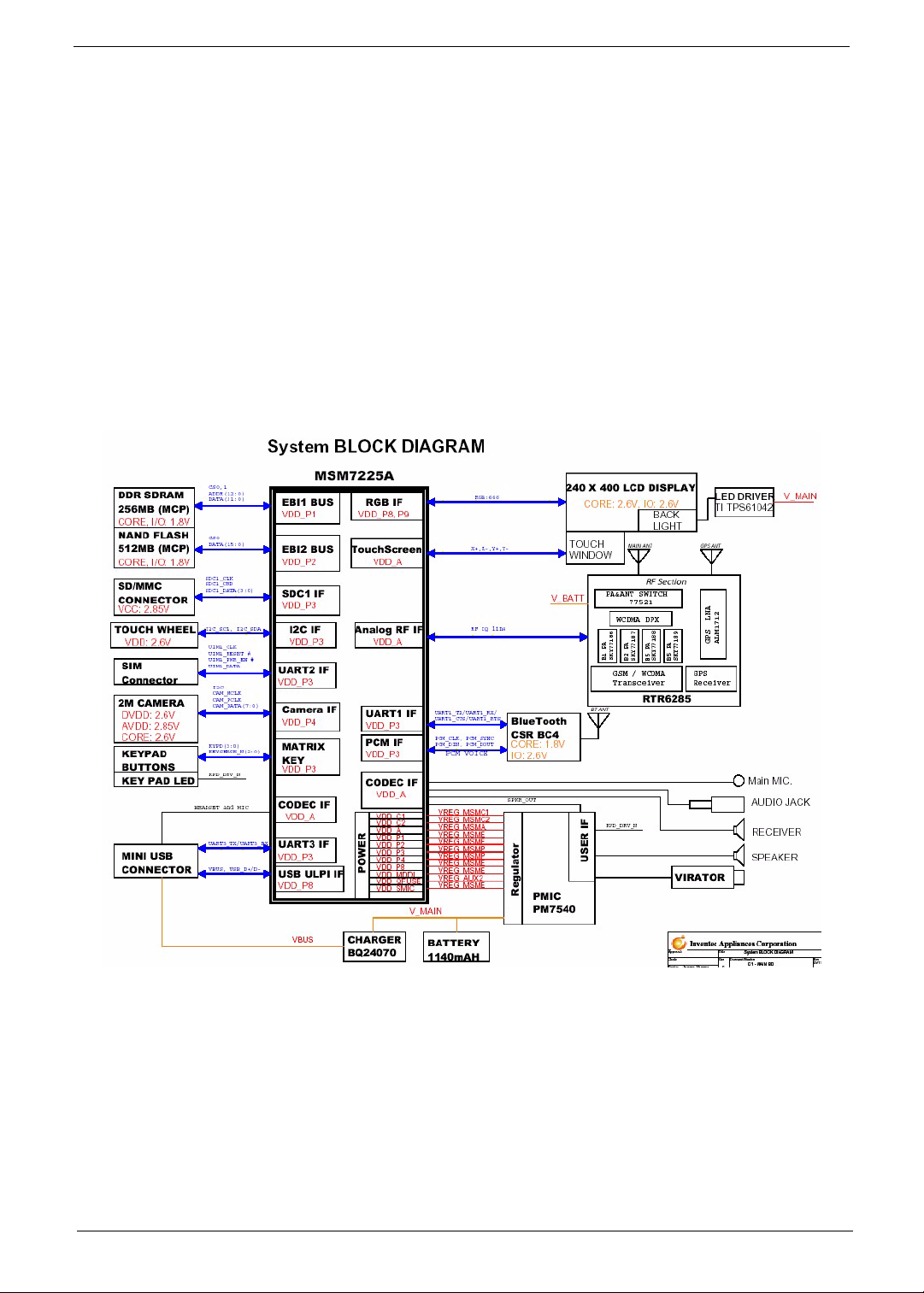
• 1.Qualcomm MSM7225 Mobile Station Modem
Memory
• 512MB Bootable NAND FLASH, 256MB SDRAM
Display
Chapter 1
• 240 x 400 TFT Liquid Crystal Display (LCD) with 18-bit color and LED back-lighting and touch
screen and 3.2" display
Dimensions and Weight
•
• g (including battery and stylus)
Communications
• Quad-band GSM/GPRS/EDGE (850/900/1800/1900MHz)
• Tri-band UMTS (2100/1900/850MHz)
• Dual-band UMTS (2100/900MHz)
Modem
• EMP U365 (POP)
Bluetooth
• Bluetooth 2.0 class 2+EDR
Camera
• Built-in 2 mega pixels camera, up to 1600 x 1200 resolution
• Supports still capture, video capture, and compression
Chapter 1 1

Expansion Options
• MicroSD card slot
Interface/Audio
• Built-in microphone and speaker, hands-free mode supported
Interface/Data
• Mini USB Sync
Ergonomic Design
• Touch panel for stylus or fingertip
• Touch wheel interface
• Buttons:
• Four control buttons
• Power button
• Camera shutter key
• Silent Button
• Volume control keys
Power
• DC Adapter, 5V, 1A
Battery
• 1 140mAh, rechargeable Lithium Polymer
• Talk time:
• Standby:
• Pocket PC usage:
Software (pre-loaded*)
• Windows Mobile@ 6.1 Professional
• Microsoft® Office Outlook Mobile (Calendar, Contacts, Tasks and Inbox)
• Microsoft® Office Word Mobile / Microsoft® Office Excel Mobile / Microsoft® Office PowerPoint
Mobile
• MSN® Messenger / Microsoft® Transcriber / Windows Media® Player 10
• Picture / Notes / Internet Explorer Mobile / ActiveSync / Calculator / Game (Solitaire, Bubble
Breaker)
• Microsoft Reader* (* depends on region)
Acer Exclusive Applications
• User interface:
• Acer Shell v2.0
• Phone Tools:
2
• Phone Application*, Phone Setting, SIM Toolkit, Speed Dial, Call Filter, Wireless Modem,
Wireless Manager, Dialer Skin, Add Ringtone, CSD Type, Voice Commander*, Connection
Wizard, SMS Sender, MMS Composer*, SIM Manager, Video Telephony, (*Subject to change
by region)
• Multimedia Tools:
• Image Maker, Multimedia Manager, Camera (Camcorder, Image Wizard), FM Tuner*
(*Subject to change by region)
• Utilities:
• Quick Link, Battery Meter, Zoom SMS, Bluetooth Manager, M-Desk, Scenario, Backup Utility ,
Name card Manager
• GPS Tools:
• Satellite Data Update, Location SMS
System Block Diagram
3
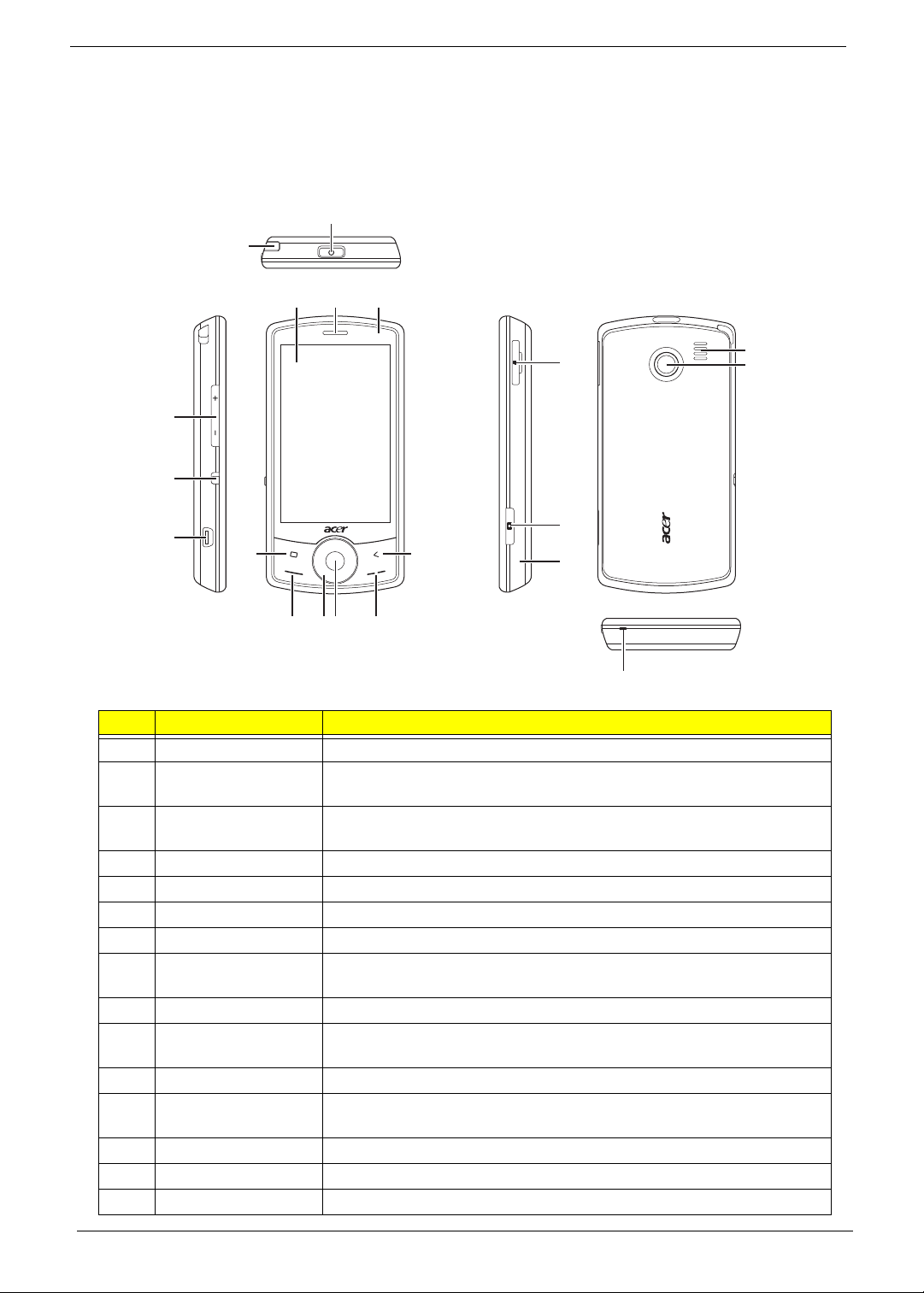
Your Acer Smartphone Tour
After examining your smartphone features, let us show you around your new smartphone.
Views
2
1
4
53
16
20
12
13
17
14
19
6
11
18
789 10
15
No. Item Description
1 Stylus Use to enter info rmation or select items on the touch screen.
2 Power button Press to turn the screen on/off or enter sleep mode; press and hold to
turn the smartphone off.
3 Touchscreen 240 x 400 pixel screen to display data, phone content and enter
information.
4 Phone speaker Emits audio from your smartphone; suit-able for holding to your ear.
5 LED Indicator Indicates if the smartphone is powered on
6 Home button Returns to the home screen
7 Call button Activate phone/dial/view recently dialed numbers/answer a call.
8 Touch wheel/4-way
button
9 Center button Use to select on-screen items
10 End button Press to end a call/disconnect GPRS; press and hold to turn the phone
1 1 Back Button Go to the previous screen
12 Volume up / Volume
down
13 Silent button Turns off speakers and turns on vibration module
14 Mini USB connector Connect to a USB cable/headphones/ charger.
15 Microphone Smartphone receiver / internal microphone
Touch-sensitive wheel control with 4-way button
function on/off.
Press to increase/reduce phone volume.
4
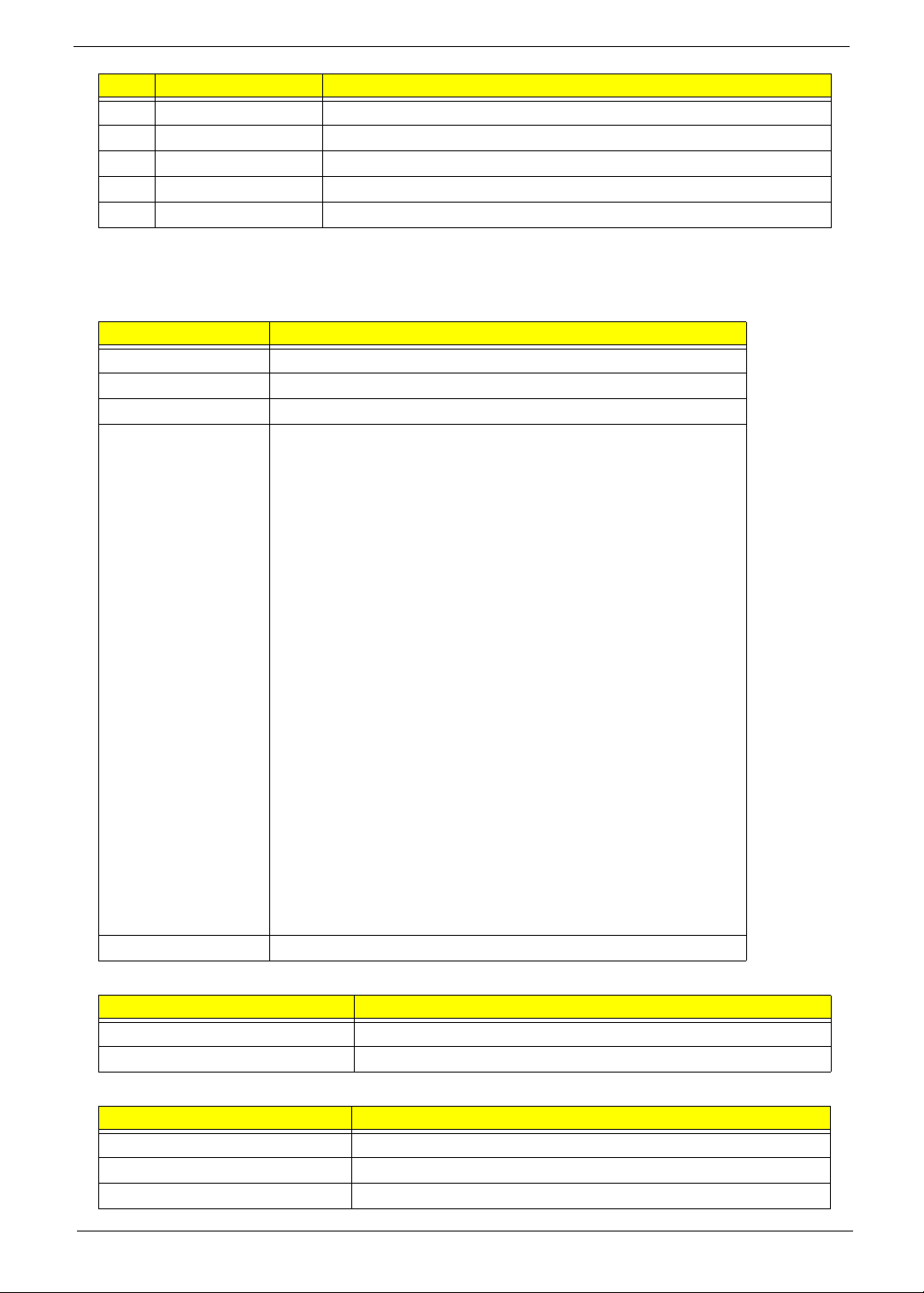
No. Item Description
16 Micro SD card slot Expand your device’s memory capacity.
17 Camera button Activate the camera or take a picture.
18 Reset pinhole Insert the stylus into this hole to reset the device.
19 Speaker Emits audio from your smartphone; suitable for handsfree use.
20 Camera A 2-megapixel camera for taking high-resolution images.
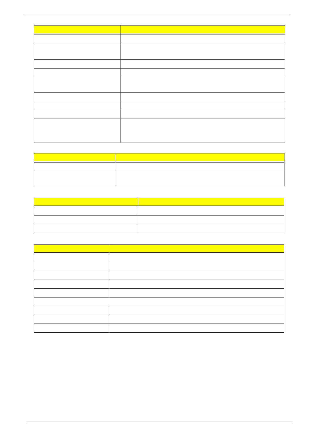
Hardware Specifications and Configurations
Chipset
Item Specification
CPU type Qualcomm MSM-7225 528MHz & 320MHz
Package 456 PINS NSP
Core Logic ARM1136-J™ & ARM926EJ-S™
Features • WCDMA/HSDPA/HSUPA
• GSM/GPRS/EGPRS
• High-performance ARM1136-J application processor running
with a running speed up to 528 MHz
• High-performance ARM926EJ-S modem processor with a
running speed up to 320 MHz
• Java hardware acceleration for faster Java-based games and
other applets
• Support for Bluetooth® 2.0 EDR via external device
• High-speed, serial mobile display digital interface that
optimizes.
• Receive diversity support for WCDMA providing improved
capacity and data throughput
• USB OTG core supports both slave and limited host
functionality.
• Built-in high-speed USB core and PHY
• Integrated wideband stereo codec for digital audio applications
• Direct interface to digital camera module with video front-end
(VFE) image processing
• GPS position location capabilities
• Vocoder support (GSM-HR, FR, EFR, AMR, AMR-WB/+)
• Advanced 11 mm × 11 mm × 1.05 mm, 0.4 mm pitch, 456-pin
NSP packaging technology
Supply voltage MSMC1 =1.325V MSMC2=1.325V
System Memory
Item Specification
Memory controller On Board
Memory size 512 MB Flash ROM, 256 MB SDRAM
TFT 3.2”
Item Specification
Vendor/model name Chimei LT320AC9003
Active Area (mm) 41.76 (W) × 69.6 (H)
Display resolution (pixels) 240 (W) × 400 (H)
5
Item Specification
Pixel Pitch (mm) 174 × 174
2
300
Typical White Luminance (cd/m
)
also called Brightness
Supported Colors 262000
Contrast Ratio 500:1
Response Time (Optical Rise
30
Time/Fall Time) msec
Weight 18 g
Physical Size (mm) 47.4(W) x 81.2(H) x 2 (D)
Electrical Interface RGB666
Viewing Angle (degree)
70
Horizontal (Right) CR = 10 (Left)
Vertical (Upper) CR = 10 (Lower)
Camera
Item Specification
Model 1/5-Inch System-On-A-Chip (SOC) CMOS Digital
Type • Built-in 2Mp resolution (1600H x 1200V) Auto-Focus CMOS
camera, up to 1600H x 1200V resolution
Bluetooth
Item Specification
Type Bluetooth 2.0, EDR
Interface UART and PCM
Profiles Generic, Serial, FTP, A2DP, Headset, Hands Free
Battery
Item Specification
Vendor & model name Simplo US473850A8T
Battery Type Li-ion Polymer
Rating 3.7 VDC
Maximum Charging Voltage 4.2 VDC
Pack capacity 1140 mAh
Battery Life
Talk time 5~6 Hr.
Standby 400 Hr.
Pocket PC usage 4 hours (Backlight on)
6

Software Upgrades
System Requirements
• Microsoft® Windows XP or above
• Latest version of EUU (End-user Upgrade Utility / EUU_xxx.exe)
• Latest version of ActiveSync v4.5 or above
• Tool: USB Cable
Mode Switching
Performing a Soft Reset
1. Press and hold the POWER button.
2. Press RESET and release both (power & reset) buttons at the same time.
Chapter 2
Switching to Download Mode
1. Press and hold the RESET button immediately after doing a soft-reset.
2. Release the RESET button after the USBDL screen shows up on the screen.
Performing a Clean Boot.
1. Perform a soft-reset, device reboot.
2. Press and hold RESET after the logo screen appears.
3. When the confirmation message appears, press the camera button immediately to perform a clean-boot.
Software Upgrade Procedure
Using the Device Software Update Utility
Before updating, please ensure the PC being used to update has the following:
• Windows XP SP2 or later versions (Vista, Windows 7) of the Windows operating system.
• ActiveSync 4.5 or higher
• All firewalls disabled
1. If a Micro SD card is installed in the Smartphone, remove it.
2. Connect the Smartphone to the PC using a USB cable.
3. Execute ActiveSync.
NOTE: If you encounter difficulties connecting with ActiveSync, try di sabling advanced network functionality
on the Smartphone by clicking Start > Settings > Connections >USB to PC and uncheck Enable
advanced network functionality.
Chapter 2 7
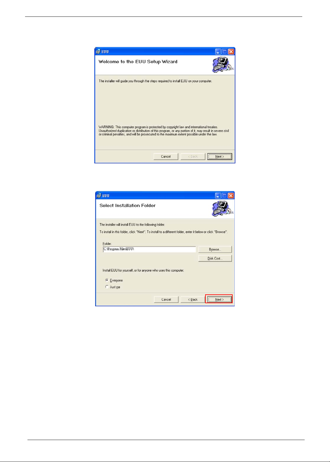
4. Execute the EUU executable file
The Welcome screen displays.
5. Click Next.
Specify a folder and permission.
8
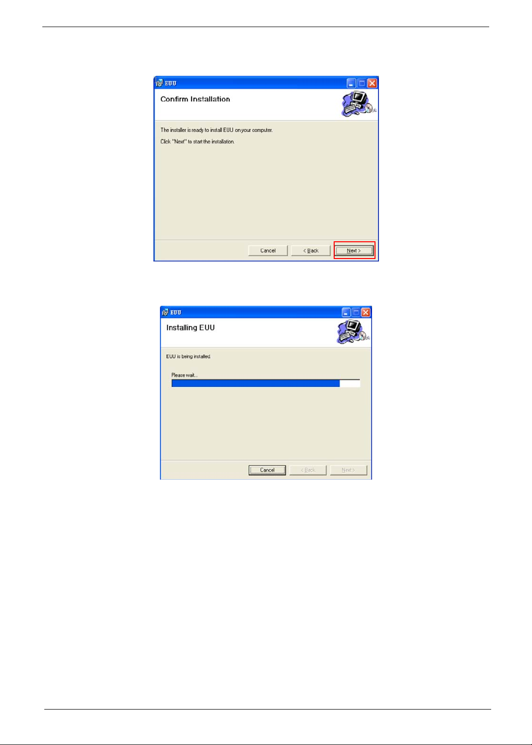
6. Click Next.
The Confirm Installation screen displays.
7. Click Next.
When EUU is installed, the Completed screen displays.
9
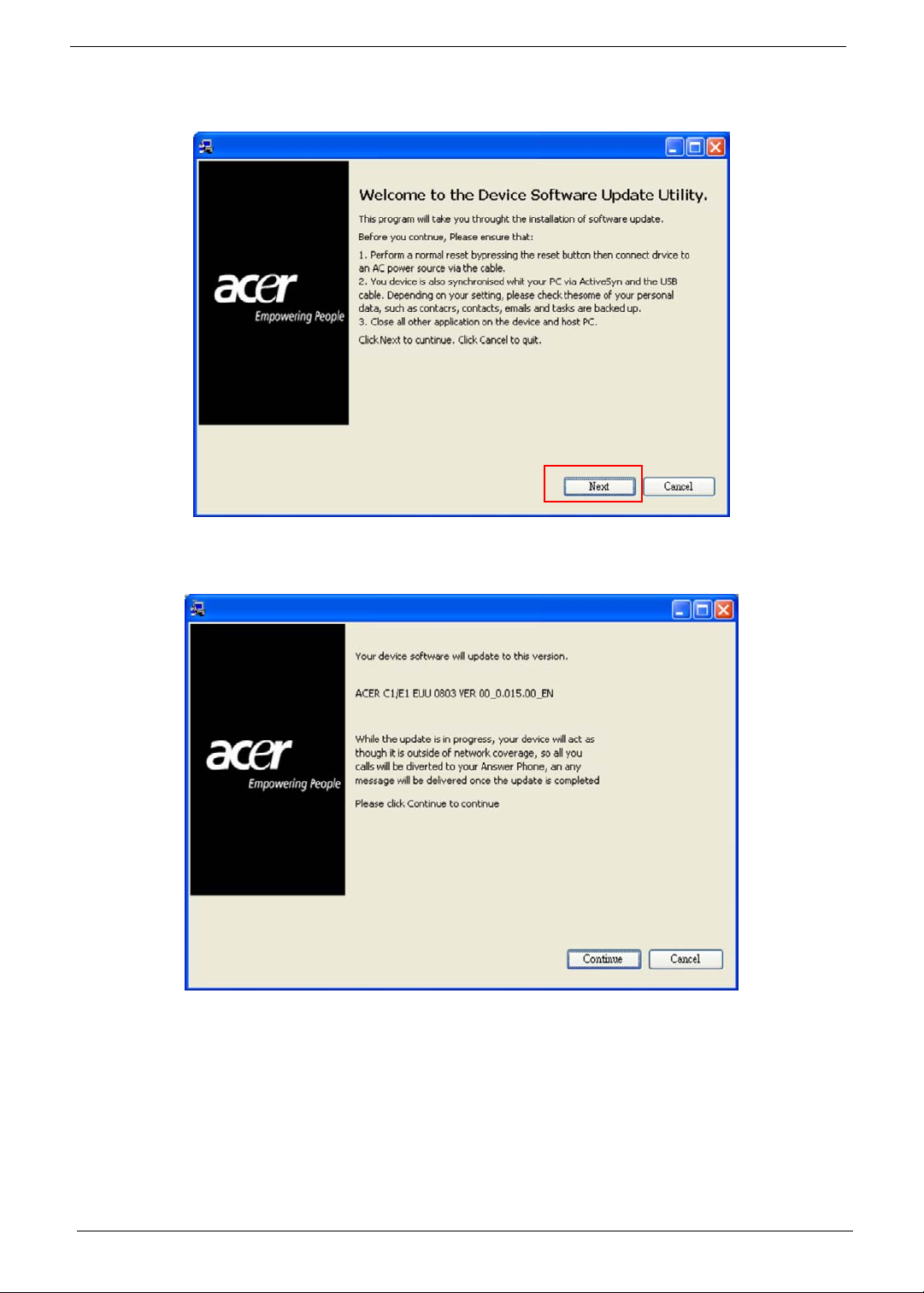
8. Click Finish.
The Device Software Update Utility starts and the following screen displays.
9. Follow the on screen instructions. When the ActiveSync connection is established, click Next.
The following screen displays.
10
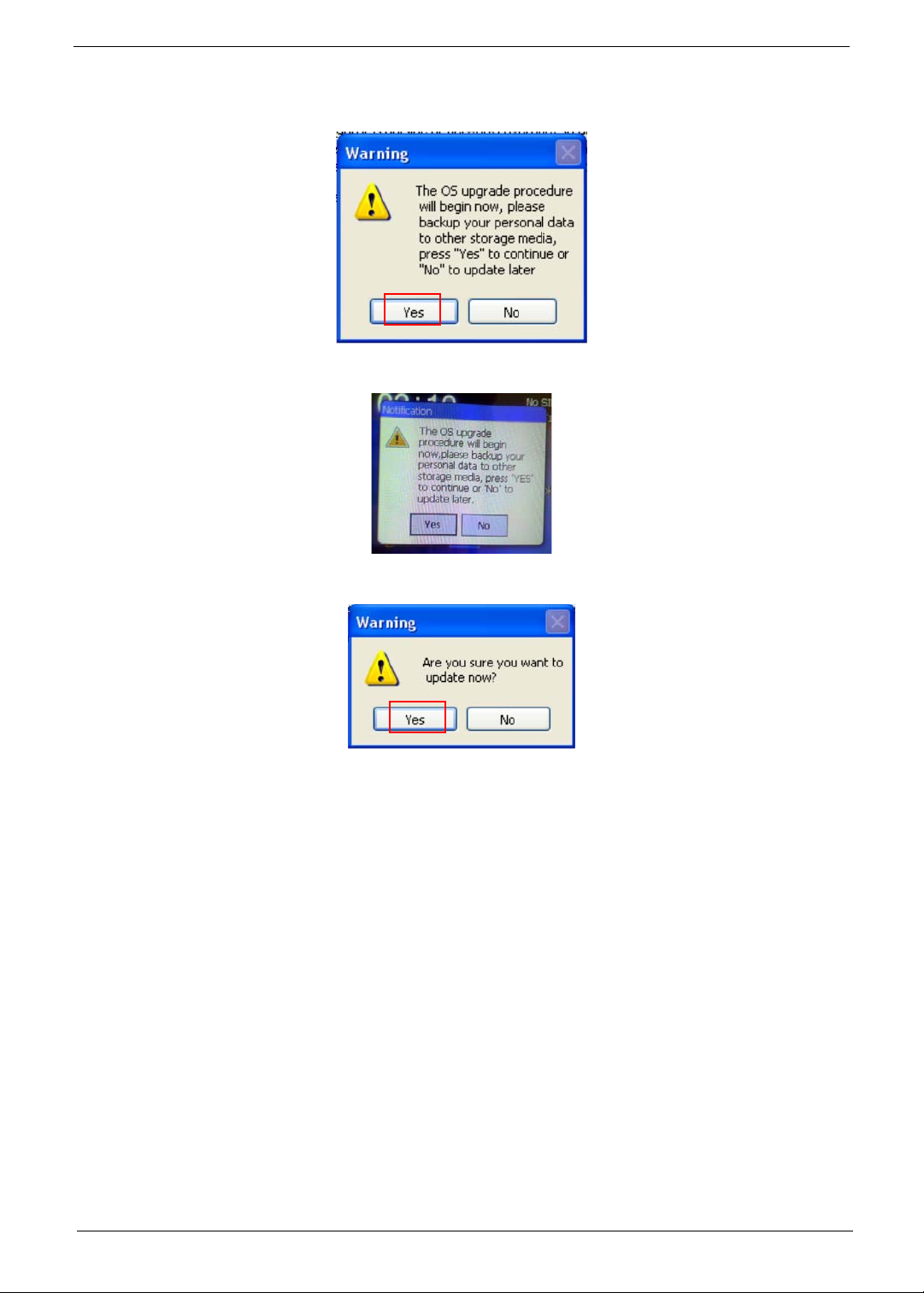
10. Click Continue.
A warning screen displays.
11. Click Yes. A confirmation screen appears on the Smartphone.
12. Click Yes. A final confirmation screen appears on the PC.
11
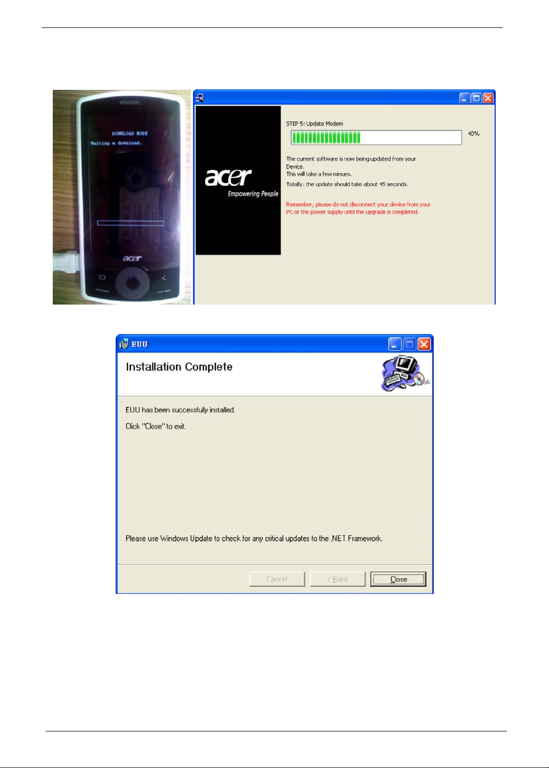
13. Click Yes to begin the upgrade.
The Smartphone reboots to download mode and the following progress screens display on the
Smartphone and PC.
The update is complete when the following screen displays.
14. Click Close to exit the utility.
12

Chapter 3
Machine Disassembly and Replacement
This chapter contains step-by-step procedures on how to disassemble and reassemble the smartphone for
maintenance and troubleshooting.
IMPORTANT:The use of metal tools during disassembl y may damage the casing. Use plastic tools where
possible.
IMPORTANT:Cover the work area with a clean, dry, lint-free cloth before placing the smartphone face down.
NOTE: The color and layout of some components may differ from those shown in the images.
Disassembly Requirements
To disassemble the smartphone, you need the following tools:
• Wrist grounding strap and conductive mat to prevent electrostatic discharge
• A clean, dry, lint free cloth to prevent damage to the LCD during disassembly
• Plastic pry less than or equal to 0.96 mm thickness
• Appropriate driver types and sizes for the indicated screws
• Tweezers (plastic and metal)
NOTE: The screws for the different components vary in size. During the disassembly process, group the
screws with the corresponding components to avoid mismatch when putting back the components.
Related Information
The product previews seen in the disassembly procedures may not represent the final product color or
configuration.
General Information
Pre-disassembly Instructions
IMPORTANT:Before proceeding with the disassembly procedure, make sure that you do the following:
1. Turn off the power to the system.
2. Unplug the USB adapter and all other cables from the system.
3. Cover the work area with a clean, dry, lint-free cloth to protect the TOP case.
4. Place the system on a flat, stable surface.
Disassembly Process
The disassembly process is divided into the following sections:
• External components disassembly
• Main unit disassembly
The flowcharts provided in the succeeding disassembly sections illustrate the entire disassembly sequence.
Observe the order of the sequence to avoid damage to any of the hardware components.
Chapter 3 13
Main Screw List
Screw Quantity Part No.
M 1.6X4.0,M WT NYLOK C 5 6052A0067302
I M 1.2X1.5 WT Ni GP, 6 6052A0067402
5T, M1.6X3.0 M BK Ni VER:02,GP 2 6052A0067502
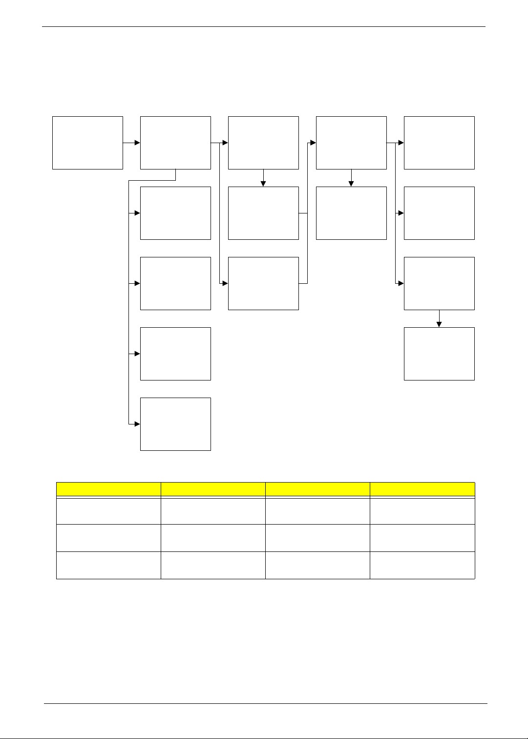
External Module Disassembly Process
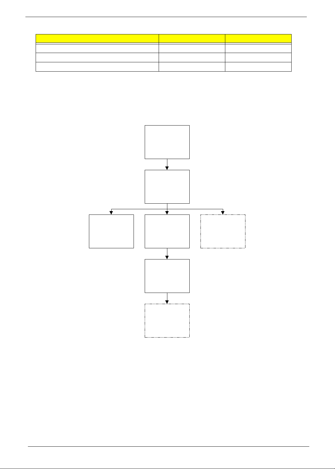
External Modules Disassembly Flowchart
Turn off system
power
Disconnect USB
cable from system
Remove
Stylus
Remove
Back Cover
Remove
Battery
Remove
SIM Card
Remove
Mini SD Card
NOTE: Items enclosed with broken lines (— - - —) are optional and may not be present.
14 Chapter 3
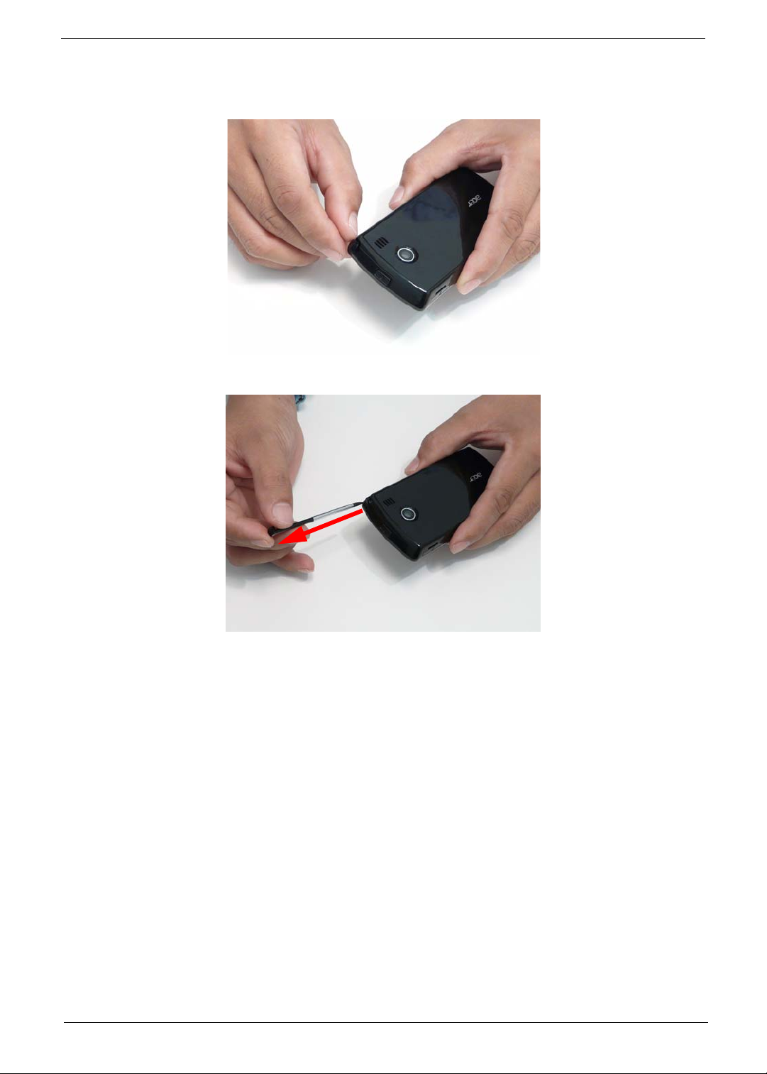
Removing the Stylus
1. Grasp the Stylus as shown and pull to remove it from the smartphone.
2. Continue to pull the Stylus until it is completely removed from the smartphone.
Chapter 3 15
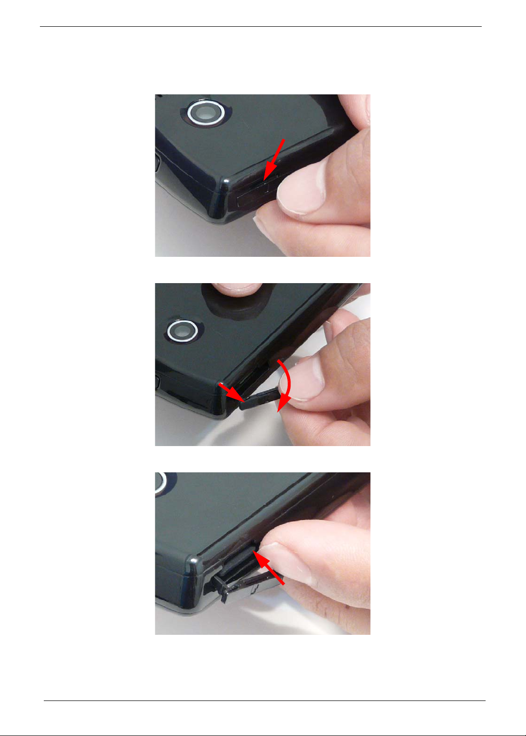
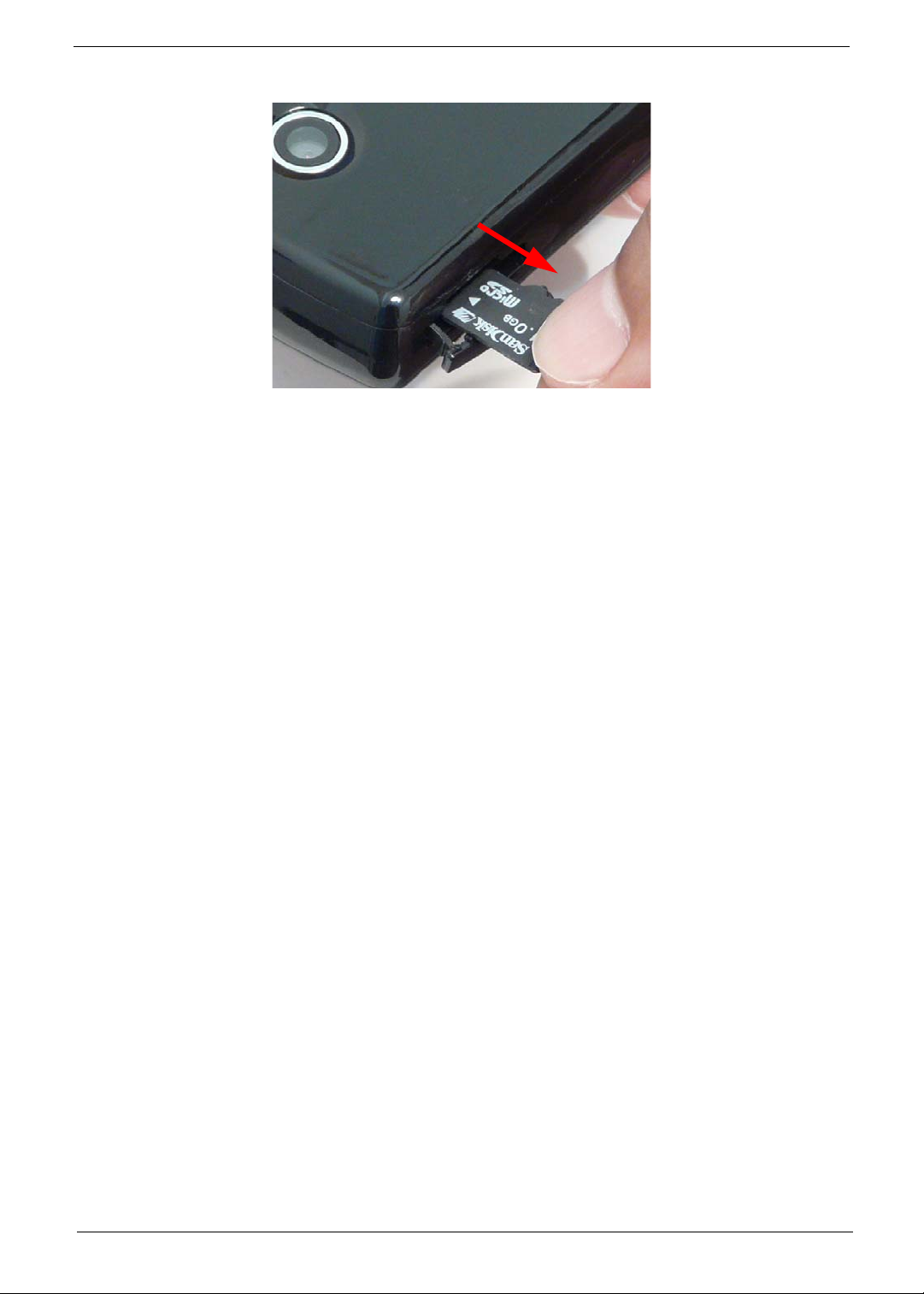
Removing the Mini-SD Card
NOTE: The Mini SD Card is an optional item and may not be present.
1. Insert a finger nail (or plastic pry) into the casing and open the Mini SD door as shown.
2. Pull the hinge out (1) and rotate the Mini SD door away from the card slot (2) as shown.
2
1
3. Press the Mini SD card into the slot and release. The card ejects automatically.
16 Chapter 3
4. Remove the card from the slot and replace the Mini SD door.
Chapter 3 17
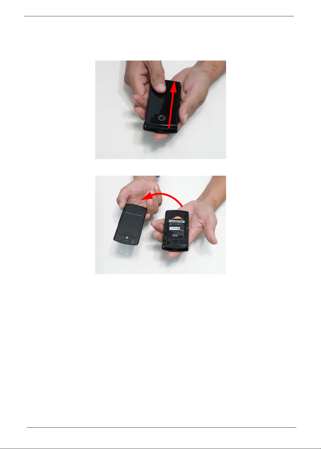
Removing the Battery Door
IMPORTANT:Cover the work area with a clean, dry, lint-free cloth before placing the smartphone face down.
1. Slide the Battery Door downwards until it disengages.
2. Rotate the Battery Door away from the smartphone to remove it.
18 Chapter 3
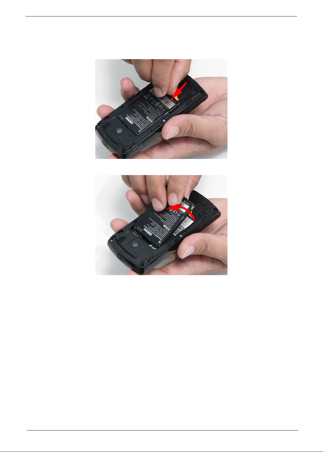
Removing the Battery
1. See “Removing the Battery Door” on page 18.
2. Push the Battery towards the top of the Smartphone as shown to release it.
3. Lift the Battery out of the battery bay.
Chapter 3 19
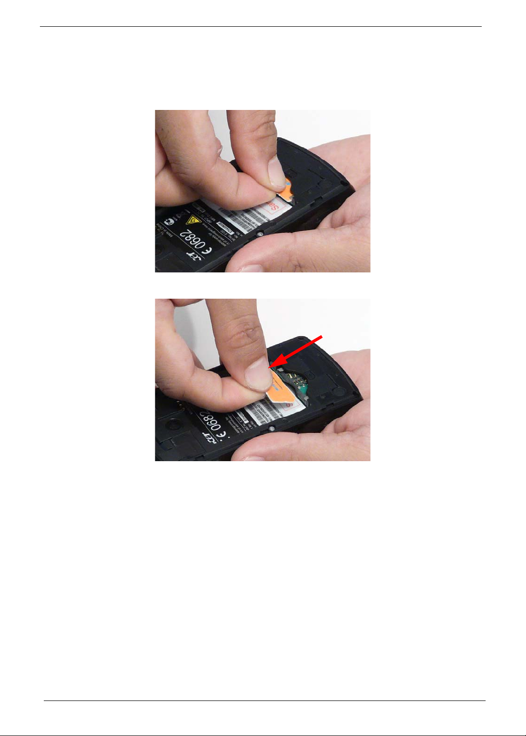
Removing the SIM Card
NOTE: The SIM Card is an optional item and may not be prese n t.
1. See “Removing the Battery” on page 19.
2. Grasp the SIM Card as shown.
3. Slide the SIM Card out of the slot as shown.
20 Chapter 3
Main Unit Disassembly Process
Main Unit Disassembly Flowchart
Remove External
Modules before
proceeding
Remove
Back Cover
Remove
Vibration Module
Remove
Speaker Module
Remove
Control Buttons
Remove
Camera Shielding
Remove
Camera Module
Remove
Sim Daughter
Board
Remove
Mainboard
Remove
LCD Panel
Remove
Receiver Module
Remove
LED Gasket
Remove
Button Board
Remove
Keyboard
Remove
Microphone Boot
Screw List
Step Screw Quantity Part No.
Back Case M 1.6X4.0,M WT
5 6052A0067302
NYLOK C
Keyboard I M 1.2X1.5 WT Ni GP, 6 6052A0067402
SIM Daughter Board 5T, M1.6X3.0 M BK Ni
2 6052A0067502
VER:02,GP
Chapter 3 21
 Loading...