

Page 1

ACER SERVICE MANUAL
Trident EX52 compatibly model:
AT4202P
1
Page 2

THIS DOCUMENT IS FOR REPAIR SERVICE INFORMATION ONLY.
DATE:2006/02/13
2
Page 3

CONTENTS
1、SPECIFICATION ..................................... ................ .................................... ..........…………...…..
1-1 General Sepecificaation..........................…….. ….......……....................... .....………....……. 5
1-2 Feature Summary....................................... .. ........ .............................……………...………….. 6
1-3 External Interface........................................... .. .........................................…………….....…… 7
1-3-1 Video/Audio Inputs……........................... .. ................. .. .. ...................... .............….. 8
1-3-1-1 TV Antenna Interface............. .. ................. .......... .. ................ .. .. ..............……… 8
1-3-1-2 Component Intputs........................................ ....... ....... . ...... ..................…………… 8
1-3-1-3 PC Input……………………………………………………………………………………… 8
1-3-1-4 DVI input……………………………………………………………………………………… 10
1-3-1-5 SCART Input……………………………………………………………………………… 11
1-3-2 Audio/Video Outputs………………………………………………………………………….. 12
1-3-2-1 Composite Video Output ……………………………………………………………….. 12
1-3-2-2 Analog Audio Output……………………………………………………………………… 12
1-3-2-3 Head Phone………………………………………………………………………………… 12
1-3-3Power Interface………………………………………………………………………………….. 12
1-3-3-1 Power Connector………………………………………………………………………….. 12
1-3-3-2 Power Input Range………………………………………………………………………… 13
1-3-3-3 Power Consumption……………………………………………………………………… 13
1-3-4 Service Interface……………………………………………………………………………….. 13
1-4 User interface………………………………………………………………………………………….. 14
1-4-1 Power Indicator……………………………………………………………………………….. 14
1-4-2 Remote Control Receiver…………………………………………………………………….. 14
1-5 External Mounting Requirements………………………………………………………………….. 14
1-6 Environmental Requirements ………………………………………………………………………. 14
1-6-1 Temperature Ranges………………………………………………………………………….. 14
1-6-2 Humidity…………………………………………………………………………………………. 14
1-6-3 Altitude………………………………………………………………………………………….. 14
1-6-4 Vibration and Shock………………………………………………………………………….. 14
2、Precautions and Notices......................... ..............................................................……………...…
2-1 Precaution of assembly……………..…... ............... ...... . ........... ............................................. 14
2-2 Precaution of Operation…………..…... ....... ................. ............ ..............................…………. 14
3、Operation.............................................. .... .....……………...............……………...………………….
3-1 Operation of Remote Control Transmitter…….... ..... .......................................………………. 16
3-2 Key function..................................................... ............. ..............................…………..…….. 17
3-3 OSD Main Explanation................................................................................................…….. 17
3-3-1 Main Menu ..................................................................................................................... 17
3-3-2 Search Menu………………………………………………................. ....................... 18
3-3-3 Video Menu.............................. ................................... . ............................................... 20
3-3-4 Audio Menu................................. ................................... . .............................................. 20
3-3-5 Time Menu................................. ................................... . .............................................. 21
3-3-6 Setting Menu................................ ................................... ............................................. 21
3-3-7 Screen Menu………………………………………………………………………………….. 22
3-3-8 Pip Menu………………………………………………………………………………………. 23
3-8-1-1 PIP Input Mode……………………………………………………………………….. 24
3-8-1-2 PIP Function Table List……………………………………………………………….. 24
4
14
16
Page 3 of 99
Page 4

4、Trouble shooting chart.......................................... .................................. ....................………….....
24
4-1 PANEL Trouble shooting…….………...................................... .....................................……… 24
4-2 Solution process of MGPC0……………………................ ...... ....... ........... ...... ................ ...... 25
4-2-1 Panel cannot be lit up………………............................... ....................................………. 25
4-2-1-1 Check peripheral circuits procedure....................... ....................................………. 25
4-2-1-2 Check Image board procedure…............................. ....................................……… 26
4-2-2 Picture Display --Dynamic picture abnormal………………………………………………. 27
4-2-3 DVI picture abnormal…………...................................... ........................... .......……….. 28
4-2-4 Component picture abnormal…...................................... .............. .......................……. 29
4-2-5 RGB Picture Abnormal……………………….............................. ................... .......... ….. 30
4-2-6 Video Picture Abnormal………………………………………………………………………. 31
4-2-7 DC Power Supply…………………………………………………………………………….. 32
4-3 TUNER&AUDIO BOARD FAULTS HANDLING…………………………………………………… 33
4-3-1 Check DC Power Supply…………………………………………………………………………… 33
4-3-2 Tuner Faults Handling…….………………………………………………………………………. 33
4-3-3 Tuner&Audio Board Faults Handling……..……………………………………………………… 34
5、White-Balance Adjustment…………………………………………………………………………………
35
5-1 Equipments list………..…………………………………. ………………………………………….. 35
5-2 Preparation and Adjustment process………. ……………………………………………………. 35
6、DDC program and test……………………………………...……………………………………….……….
37
6-1 Equipments list and prepare……………………...………………………………………………… 37
6-2 Program and test process………...………..………………………………………………………… 37
7、Flash Update………………………………………...………………………………………………………
38
7-1 The list of Instrument………………………………………………………………………………….. 38
7-2 The operation explaining Flash Update…………………………………………………………….. 38
8、Software Administer Block diagram………………………………………………………………………
41
8-1 Main Block diagram (Kernel part)………………………………………………………………… 41
8-2 SOURCE key Block diagram…………………………………………………………………………... 42
8-3 MENU key Block diagram…………………………………………………………………………….. 43
8-4 Mode Check Block diagram…………………………………………………………………………. 45
8-5 SCART Key Choose Process………………………………………………………………………… 45
9、Block diagram & Explain.......................………………………..............…………………………….
49
9-1 PDP block diagram and functions…………………….. ………….. ……………………………… 49
9-2 Image board block diagram and signal introduce……………………………………..…………… 50
9-2-1 Image board block diagram………………………………………………………………………… 50
9-2-2 Input signal introduce………………………………………………………………………………… 51
9-3 TUNER board block diagram…………………………………………………………………………. 51
10、Waveform of signal………………………………..….. ………..…….. …. ……………………..……….
52
10-1 Waveform of input signal……………..….. ………..…….. …. ……………………..……………. 52
10-2 Signal waveform in the image board. ………..…….. …. ……………………..………………… 55
11、11Check and Measure…………..….. …………..…….. …. ……………………..……………………..
64
11-1 Image board………………..….. ……….. …. ……………..…….. …. ……………………..……. 64
11-1-1 Power Check and Measure….……..….. ………..…….. …. ……………………..……… 65
Page 4 of 99
Page 5

11-1-2 Voltage value of IC necessary…………………………………………………………… 66
11-2 AUDIO and TUNER Board CHECK……………………………………………………………….. 66
12、Mechanical Introduction…………………………………………………………………………………
12-1 PDP Internal view……………………………………………………………………………………. 67
12-2 Mechanical of cabinet front disassembly…………………………………………………………. 68
12-3 Disassembly and assembly……………………………………………………………………….. 69
12-3-1 PDP stand removal………………………………………………………………………… 69
12-3-2 Back Cover Removal………………………………………………………………………. 70
12-3-3 Rear Low Cover removal…………………………………………………………………… 71
12-3-4 Main Board(MGPC) and TUNER AUDIO Board (TUPC)removal……………………… 72
12-3-5 PCB Plate Removal……………………………………………………………………….. 73
12-3-6 Key Board Remove……………………………………………………………………….. 74
12-3-7 Side AV Board Removal……………………………………………………………………. 75
12-3-8 Panel Module Removal…………………………………………………………………….. 76
12-4 Panel Wiring diagram……………………………………………………………………………… 77
13、PCB LAYOUT ………………………………………………………………………………………………
13-1 Image broad PCB LAYOUT……………………………………………………………………… 79
13-2 TUNER board and AUDIO board PCB LAYOUT……………………………………………….. 80
14、Schematic diagram………………………………………………………………………………………….
67
79
83
Page 5 of 99
Page 6
1、SPECIFICATION
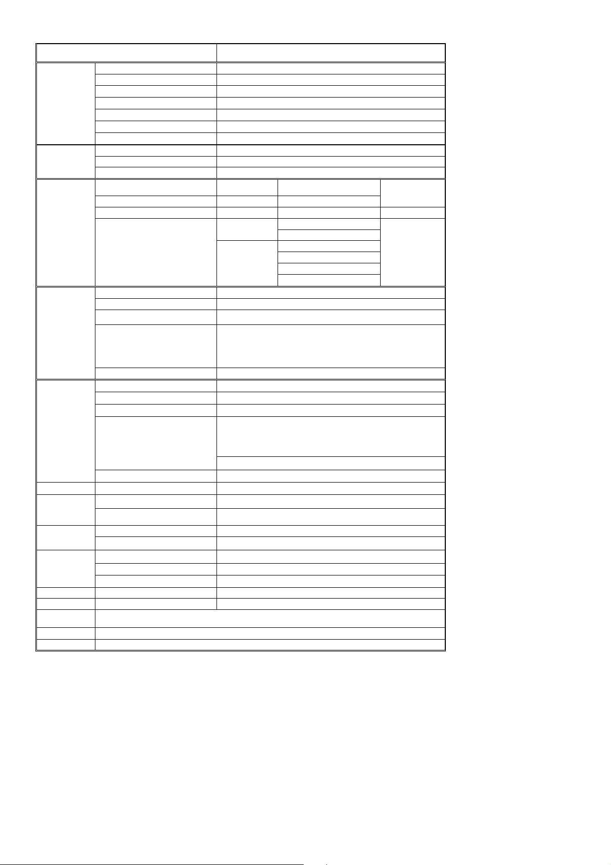
1-1-1 General Specificaation
Item Specification
Screen size 42 inch plasma display panel
Aspect 16:9
Panel
Spec
Display pixels 852 x 480 (WXGA)
Effective display size 933mm x 533mm
Number of color 16.7 million colors
Contrast Ration 10000:1 (in dark room)
Peak brightness 1500 cd/㎡
TV Tuning 1 Tuners, 100 channel save
TV Mode
Sound system D/K I B/G L/L’
Color system PAL /SECAM
Video RCA x 1 PAL, NTSC, SECAM
S-Video S-Video1 x 1 PAL, NTSC, SECAM
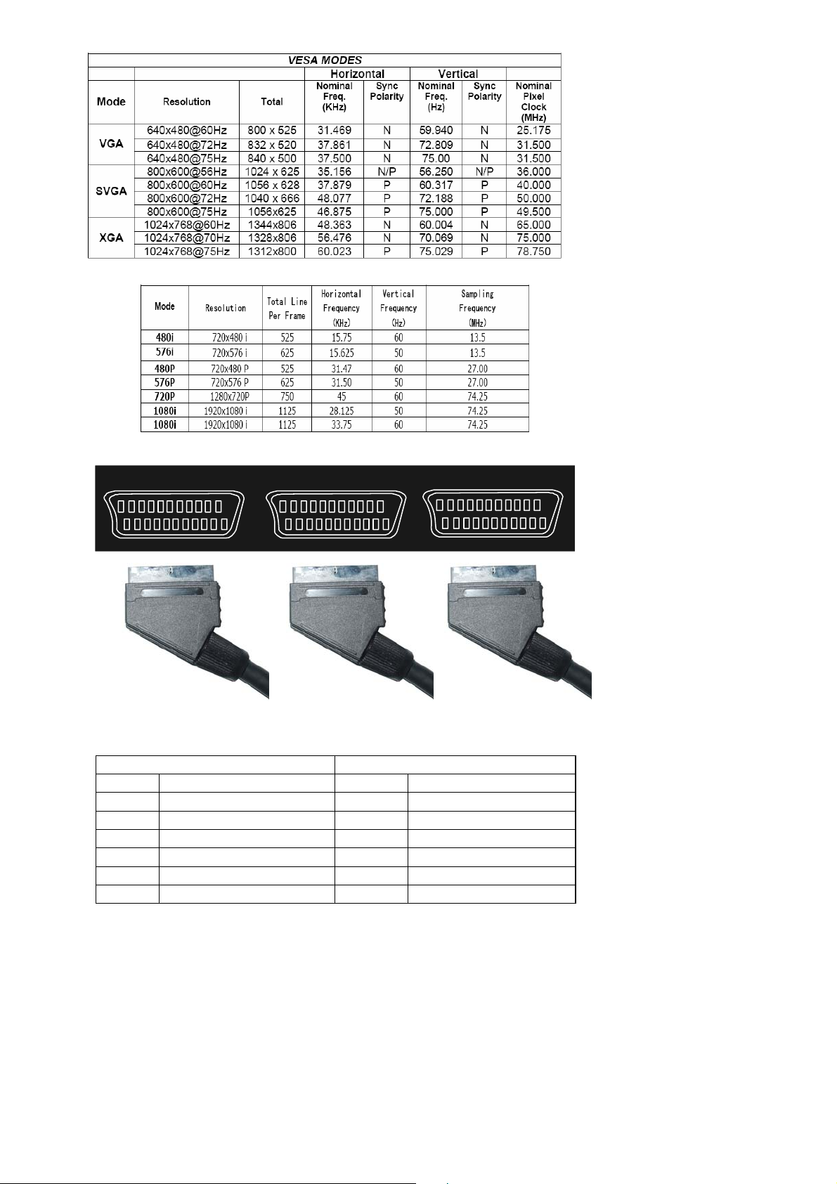
SCART Europe 21Pin SCART x 3 PAL, NTSC, SECAM Audio: L/R x 3
Video Mode
Component 1,2
(Y Pb Pr/ Y Cb Cr)
Y Cb Cr
Y,Pb,Pr
480i (60Hz)
576i (50Hz)
480P (60Hz)
720P (60Hz)
(HDTV)
1080i(50/60HZ)
Signal input Analog:D-Sub 15 pin
Plug and play DDC / 2B
Support Frequency FH:31KHz to 69KHz , FV:56Hz to 75Hz
PC Mode
RGB Mode(D-Sub Mode)
VESA: 640 x 480 (60Hz/72Hz/75Hz)
VESA: 800 x 600 (56Hz/60Hz/72Hz/75Hz)
VESA: 1024 x 768 (60Hz/72Hz/75Hz)
VESA: 1280 x 1024 (60Hz)
RGB Mode (D-Sub Audio) Earphone (3.5ø)
Signal input Digital:DVI-D 24 pin
Plug and play DDC / 2B
Support Frequency FH:31KHz to 69KHz , FV:56Hz to 75Hz
VESA: 640 x 480 (60Hz/72Hz/75Hz)
DVI Mode
DVIMode
VESA: 800 x 600 (56Hz/60Hz/72Hz/75Hz)
VESA: 1024 x 768 (60Hz/72Hz/75Hz)
VESA: 1280 x 1024 (60Hz)
480i,576i,480P, 576P, 720P, 1080i(50/60Hz).
DVI Audio Earphone (3.5ø)
Video Out SCART Europe 21Pin PAL, NTSC, SECAM
Speaker Amplifier External:10W × 2
Audio Out
Power
Audio Output Earphone (3.5ø)
Power input sources 100--240V~ ,50/60Hz
Power consumption 300W (Typical)
Operation Temperature + 0 °C ~ + 40 °C
Environment
Storage Temperature - 10 °C ~ + 50 °C
Humidity 10% -- 85%
Dimension Width x Height x Thickness 1060 x730 x 240 (mm)
Net weight No Accessory 37.5 Kg
Accessory
Remote Control Transmitter, Battery (AAA X 2), Power Cord, ,User’s Manual
Choose Part Wall Mounting Bracket,S-Video Cable
Audio: L/R x 1
Audio: L/R x2
576P (50Hz)
Page 6 of 99
Page 7

1-2 Feature Summary
42 inch Large Screen Flat Panel Plasma Display
Panel Resolution: WVGA (852 x 480 Pixels)
Panel Max Brightness: 1500 cd /m
2
Panel Max Contrast Ratio: 10000:1
View Angle: horizontal ≥160º/vertical ≥160º
Built-in Single-way TV Tuner, Supporting 100channels
Full Channel TV Signal Receiving: 48.25MHz ━863.25MHz
Factory presets
Teletext WST625 for Europe
Functions of Dual Language, Stereo, Mono, Single-way Video, Single-way S-Video,3 group
SCART ,Component Signal Receiving
Supports Signal Input of 480i, 480P, 576i, 576P, 720P, 1080i(50/60Hz)
TV Receiving System: PAL/SECAM BG/DK/I/L L’
Supports PC VGA Signal Receiving
DVI –D Signal(TMDS)INPUT,Support HDTV, SDTV
External Speaker 4Ω 8W×2(Option)
Internal Speaker 8Ω 5W×2
8-bit Digital Video Decoder
3D Digital Comb Filter
3:2 and 2:2 Movie modes
DLTI/DCTI Brightness, Color Digital Tuning
Digital I/P Processing, Completely Digital Progressive Display
HDSPT Duel-way High Quality Digital Image Processing
Stationary Image While Switching Channels
Built-in Graphic OSD Interface
Timer Function, Turn Off Timing
Remote Control
Displays Mode Switching (Normal, Wide Screen, Full Screen, Enlargement)
Automatic Shut Down When No Signal Input
Automatic Shut Down in Blue Screen Status without Signal Input
Shows Blue Screen When No Signal Input
Microprocessor controlled scan technology
Page 7 of 99
Page 8
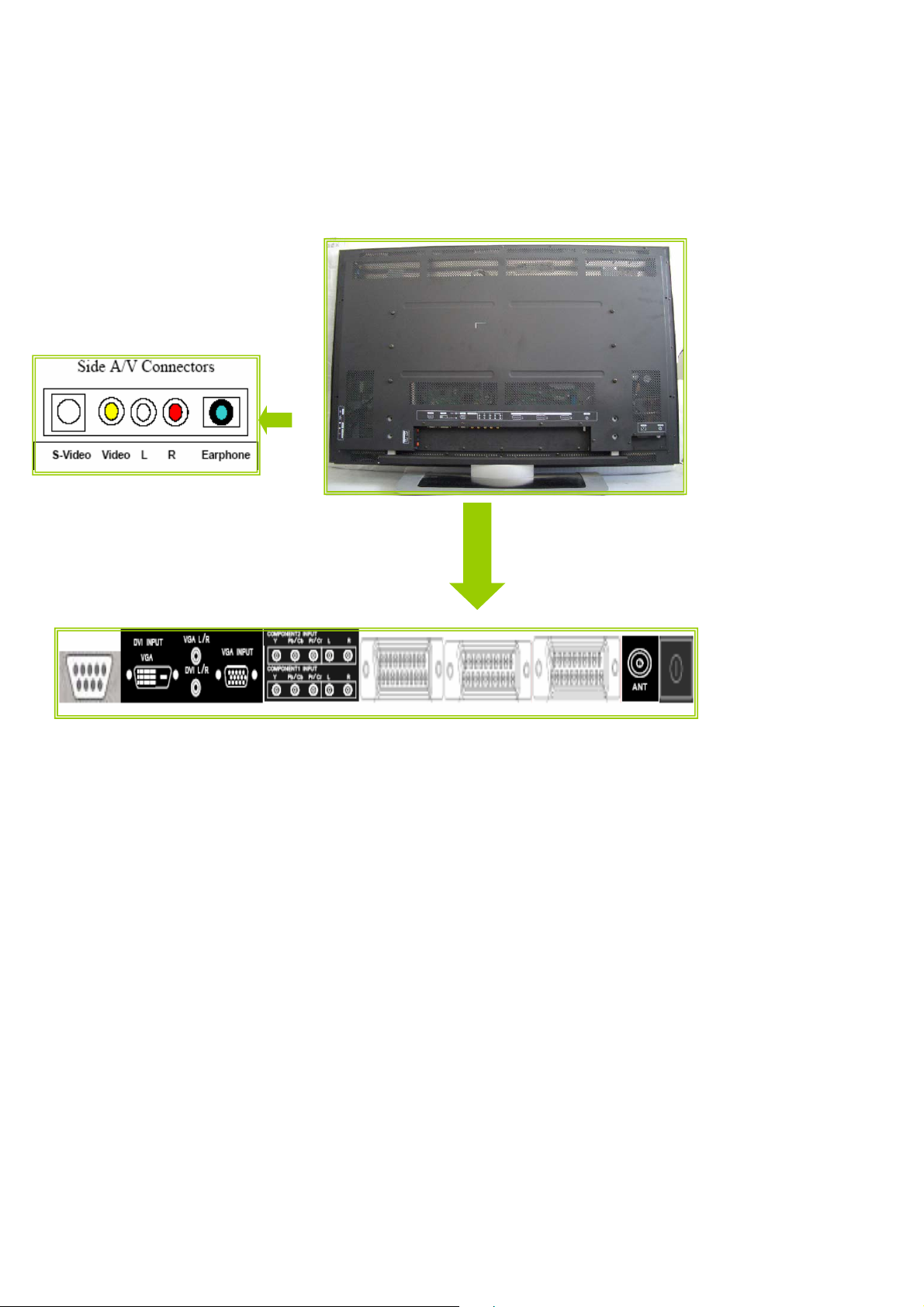
1-3 External Interface
Most of these interfaces are located at the back-panel. There’s also a group of connectors located
on the side of this device for easier access. The following figures depict these A/V connectors.
Page 8 of 99
Page 9
1-3-1 Video/Audio Inputs
The following sections specify the video/audio inputs for P42S351
1-3-1-1 TV Antenna Interface
①. TV Antenna Connector
P42S351 shall provide a f-type cable connector with 75 ohms termination on its back panel for
reception of radio frequency signals.
②. TV Systems
PAL/SECAM
③. TV Channel Coverage
the RF tuner shall be capable of covering 48.25MHZ to 863.25MHZ and tuning to the following
channels:
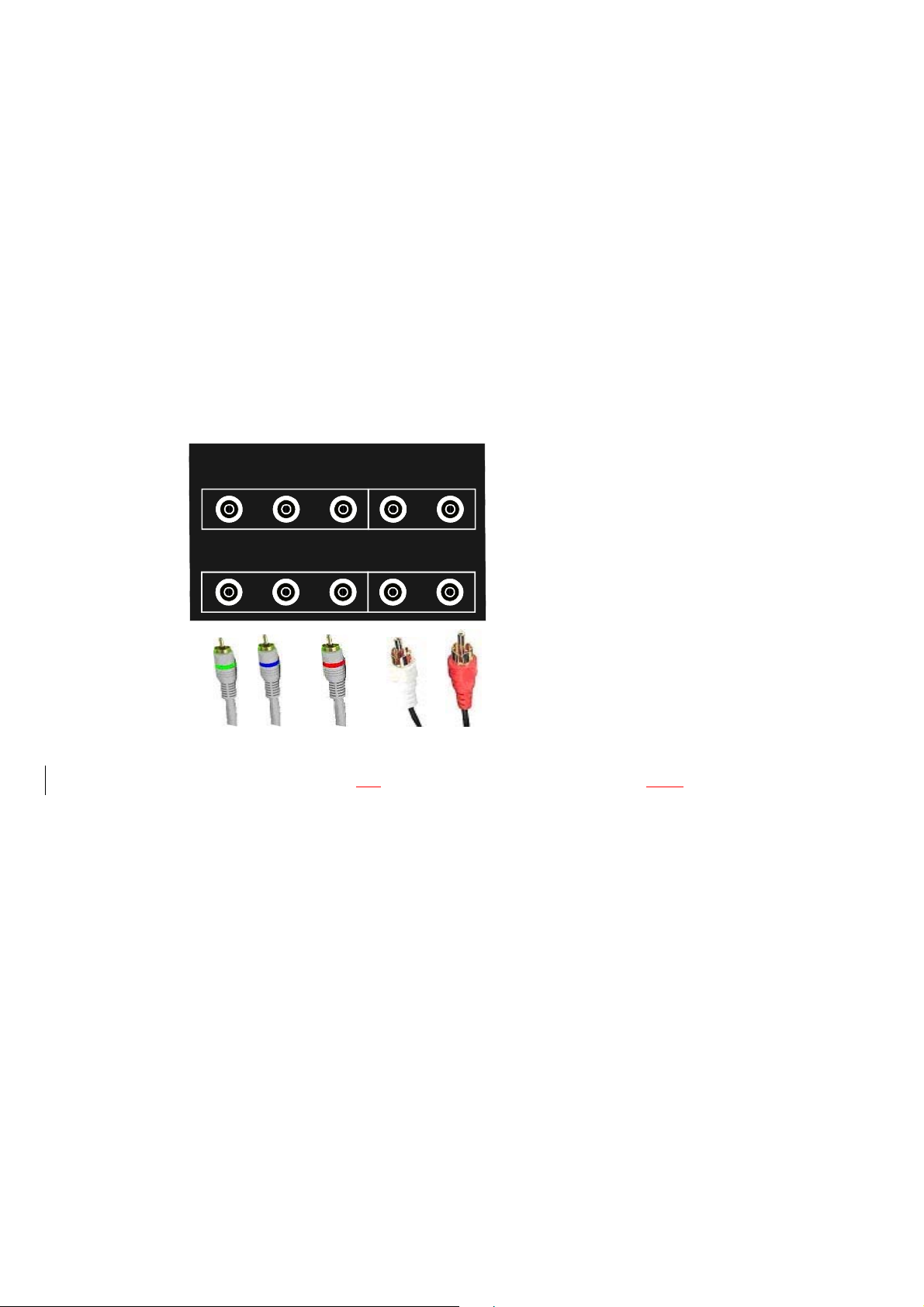
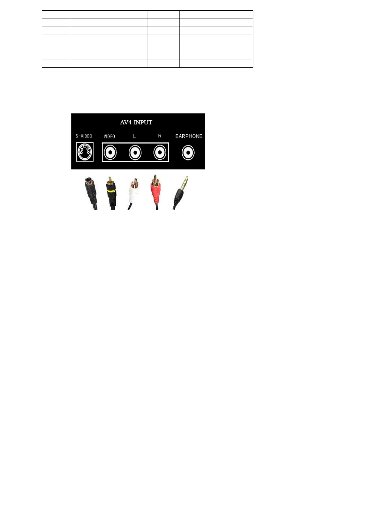
1-3-1-2 Component Intputs
We have AV input jacks for VIDEO/AUDIO and S-VIDEO/AUDIO.
COMPONENT1 INPUT
YPbCbPrCrL R
/ /
COMPONENT2 INPUT
YPbCbPrCrL R
/ /
If your DVD or VCD player is equipped with Y PbPr(Y Cb Cr) signal output, you can connect these
signals to the component signal input end of the TV to get better image quality, as the figure shows.
Note: when you find picture scrolling, the
above,e check the connection. Please check if the color of the cable matches the color of the
input socket.
1-3-1-3 PC Input
P42S351 accommodates a VGA type computer connection as specified below.
①. Connect D-SUB signal cable(VGA cable, RGB cable)from PC to D-SUB jack at the back
of this TV Set. And connect the earphone cable from PC earphone output jack to AUIDO
input jack near to the D-SUB jack.
Setup:
Use the key “SOURCE”in Remote Control or “MODE”key on the front control keypad, select the
wrong color or no color, no image or all of the
Page 9 of 99
Page 10
source to “D-SUB” state. Then turn on the PC.
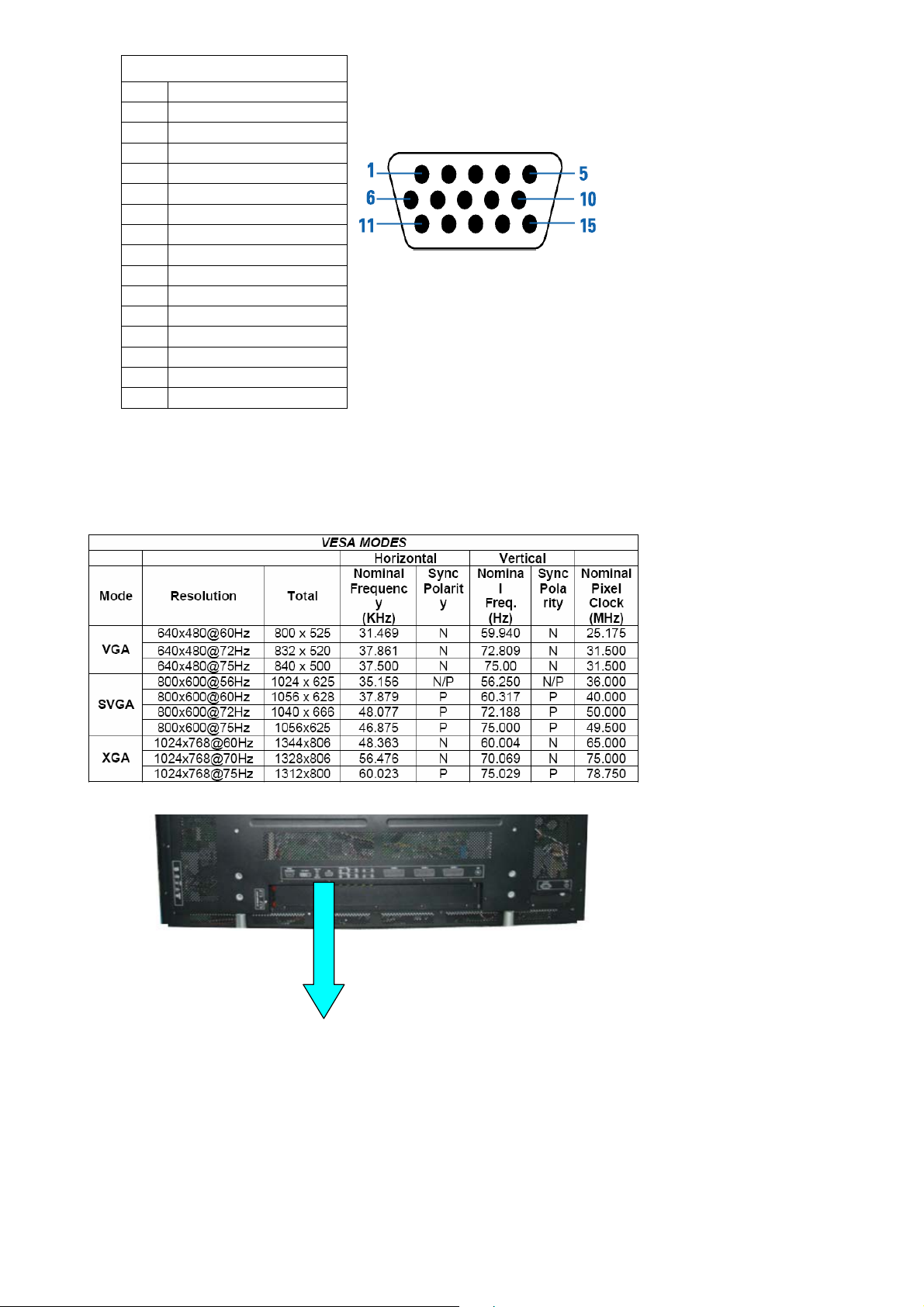
Pin – Assignment of 15-pin
NO FUCTION
1 Red Video
2 Green Video
3 Blue Video
4 ID2
5 Ground
6 Red Ground
7 Green Ground
8 Blue Ground
9 NC
10 Sync Ground
11 I D 0
12 Serial Data for DDC
13 H-Sync.
14 V-Sync.
15 Serial Clock for DDC
②.Audio Inputs
P42S351 shall provide a 3.5 mm jack for the stereo audio signal associated with VGAinput.
③. Input Formats
P42S351 shall support the following input format on its VGA input.
④. Connecter
Page 10 of 99
Page 11
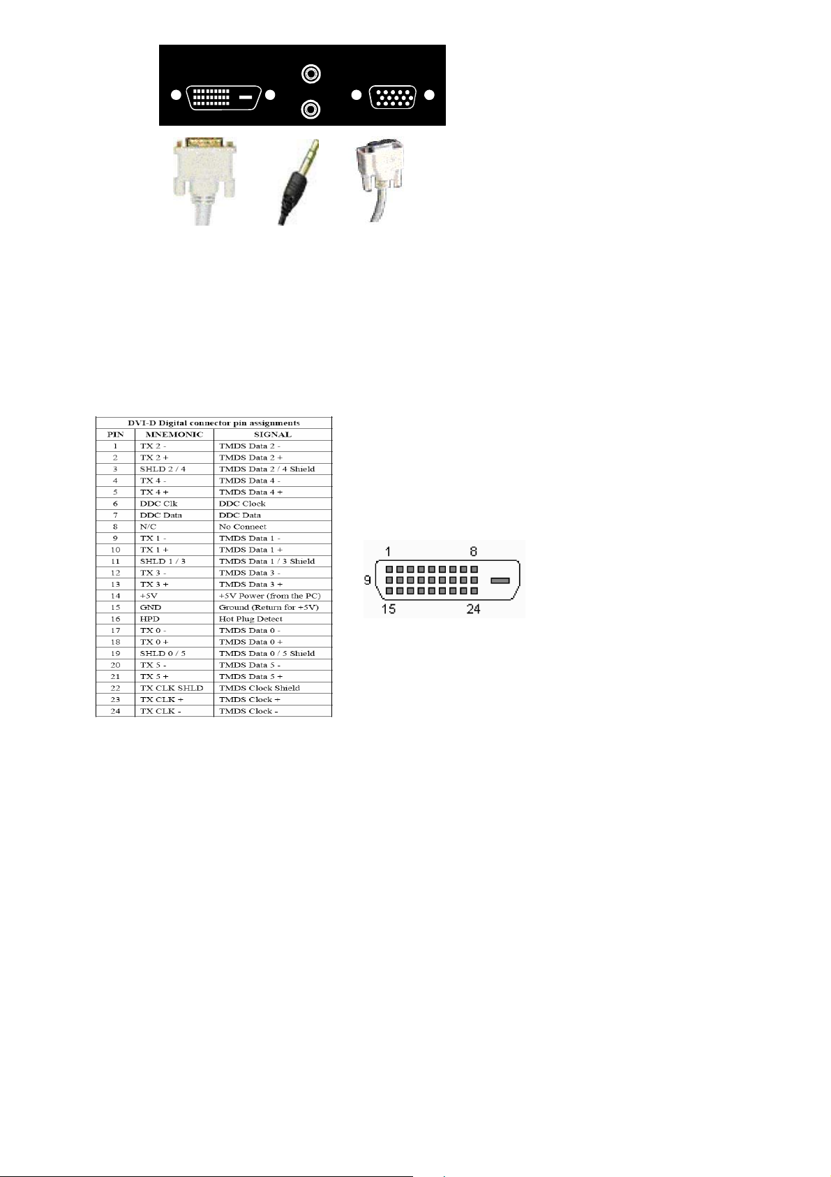
DVI INPUT
VGA
VGA L R
/
DVI L R
/
VGA INPUT
1-3-1-4 DVI input
P42S351 shall accommodate a DVI type digital video source as specified in this section.
①. Video Inputs
Connect DVI-D 24 Pin signal cable(TMDS cable)from equipment with DVI-D jack to the back of
this TV Set. And connect the earphone cable from equipment with earphone output jack to AUIDO
input jack near the DVI-D jack.
Setup:
Use the key “SOURCE”in Remote Control or “MODE”key on the front control keypad, select
source to “DVI”state. Then turn on the equipment.
②. Audio Inputs
P42S351 shall provide a 3.5 mm jack for the stereo audio signal associated with DVI input.
③. HDCP support
HDCP must be supported on the DVI input. Refer to the High-bandwidth Digital Content
Protection System specification version 1.1 for details.
④. Input Formats
Page 11 of 99
Page 12
P42S351 shall support the following input format on its DVI input.
A
A
A
A
A
A
1-3-1-5 SCART Input
We have three SCART signal input jacks .
Scart Connector male
PIN1
PIN3
PIN4
PIN7 Blue out PIN7 Blue in
PIN5 Blue return PIN5 Blue return
PIN11 Green out PIN11 Green in
PIN9 Green return PIN9 Green return
SCART 1
SCART 2
Output connector Input connector
udio right out PIN2
udio left (or mono) out PIN6
udio return PIN4
udio right in
udio left (or mono) in
udio return
SCART 3
Page 12 of 99
Page 13
PIN15 Red out PIN15 Red in
PIN13 Red return PIN13 Red return
PIN16 RGB status out PIN16 RGB status in
PIN14 RGB status return PIN14 RGB status return
PIN19 Sync (composite video) out PIN20 Sync (composite video) in
PIN17 Sync return PIN 18 Sync return
PIN 21 Shield PIN 21 Shield
1-3-2 Audio/Video Outputs
1-3-2-1 Composite Video Output
P42S351 shall provide a RCA type receptacle on its back panel for composite video output.
(Side board)
1-3-2-2 Analog Audio Output
P42S351 shall provide two RCA type receptacles for external connection to a stereo
amplifier.
1-3-2-3 Head Phone
P42S351 shall provide a 3.5 mm jack at side of 42MF130A/37 for external connection of a
stereo headphone.
1-3-3 Power Interface
1-3-3-1 Power Connector
P42S351 shall support an IEC C-13/C-14 (Standard) type male power receptacle for
connection to AC power source.
1-3-3-2 Power Input Range
The operating range shall be from 100 to 240 VAC sinusoidal. Input power frequency range shall be
from 50 to 60 Hz over the specified input voltage range.
1-3-3-3 Power Consumption
The monitor is equipped with a power-management function (DPMS) for analogRGB and component
Page 13 of 99
Page 14
RGB input when DPMS setting is actived.There is a delay, according to the DPMS setting before the
transition from Onstate to any power saving state to avoid unintentionally entering of a power saving
stage during display resolution and timing mode changes. Transition from any power saving state to
another can be instantaneous. The recovery from Off-state requires no manual power on.
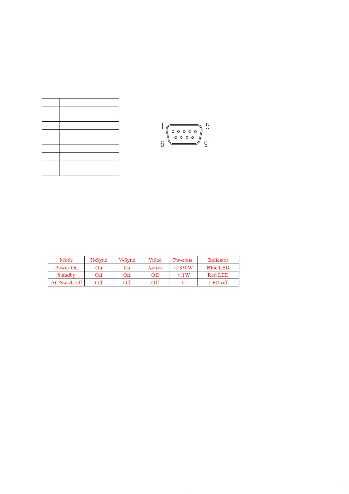
1-3-4 Service Interface
P42S351 shall provide a 9-pin D-sub connector on its back panel for firmware upgrading purpose.
This interface shall conform to RS-232 standard with the following pin-outs.
9PIN For Software Update And External Control
NO FUCTION
1 NC
2 TXD transmitted data
3 RXD received data
4 NC
5 FG frame ground
6 NC
7 NC
8 NC
9 NC
The method of firmware upgrading please see “Flash update process” chapter.
1-4 User interface
1-4-1 Power Indicator
P42S351 shall make use of an LED type indicator located on the front of leftthe display.
The LED color shall indicate the power states as given in the following table.
LED colors
1-4-2 Remote Control Receiver
P42S351 shall provide an infra-red (IR) optical detector on its front panel for use as the
receiver for remote controller signal. The IR communication protocol shall conform to RC-5
standard. The minimum IR reception angles shall be +/- 30 degrees horizontally and vertically.
The required operating distance of the remote control shall be 7 m.
1-5 External Mounting Requirements (Unpacked for a long time)
42MF130A/37 shall be designed so that the display enclosure can be easily removed from the
Page 14 of 99
Page 15

base for external mounting applications. When the base is removed, there shall be no additional
non-removable parts that are visible from the front of the display
1-6 Environmental Requirements
1-6-1 Temperature Ranges
Operating Temperature……………………………………………………..0°C to 40°C
Storage Temperature……………………………………………….. …….10°C ~ + 50°C
1-6-2 Humidity
Operating …………………………………………………………………… 10% ~ 85%
Storage Relative Humidity………………………………………………………5% ~ 85%
1-6-3 Altitude
Operating ............................................................... ...................... ......... (0 to 3,000 m)
Non-Operating............................... .................................... ........ . ........… (0 to 3,000 m)
1-6-4 Vibration and Shock
All testing shall be done in each of three mutually perpendicular axes, referenced to
the positionof the system as it is in front of the user (i.e., front-to-back, side-to-side,
and top-to-bottom).
2、Precautions and Notices:
2-1 Precaution of assembly
(1)Please do not press or scratch PDP panel surface with anything hard.
(2)Please wipe out PDP panel surface with absorbent cotton or soft cloth in case of it being soiled
(3)Please wipe out drops of adhesive like saliva and water in PDP panel surface immediately. They
might damage to cause panel surface variation and color change
(4)Do not apply any strong mechanical shock to the PDP panel
2-2 Precaution of Operation:
(1)Please be sure to unplug the power cord before remove the back-cover. (make sure the power is
turn-off)
(2)Please do not change variable resistance settings in PDP MODULE; They are adjusted to the
most suitable value. If they are changed, it might happen LUMINANCE does not satisfy.
(3)Please consider that PDP MODULE takes longer time to become stable of radiation characteristic
in low temperature than in room temperature.
(4)Please pay attention to displaying the same pattern for very long-time. Image might stick on PDP.
Page 15 of 99
Page 16
3、Operation
3-1 Operation of Remote Control Transmitter
Page 16 of 99
Page 17
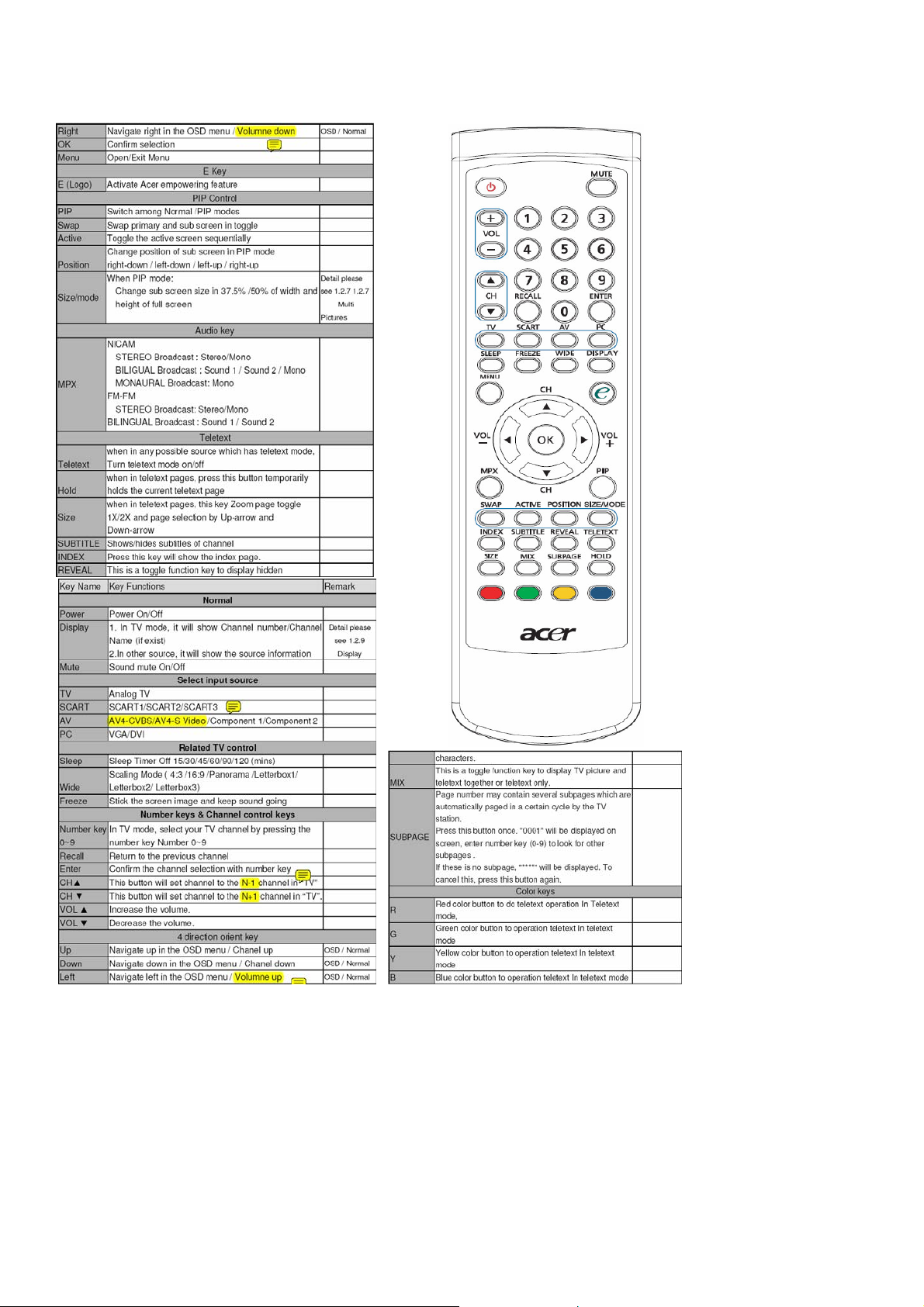
3-2 Key function
3-3 OSD Main Explanation
Main Fuction
1. Press “ MENU” key on Remote Control or the front panel to open or close the menu.
2. Press “▲▼ ” to select an item.
3. Press “►” or “Enter” to enter a sub menu item or an enable adjusted item.
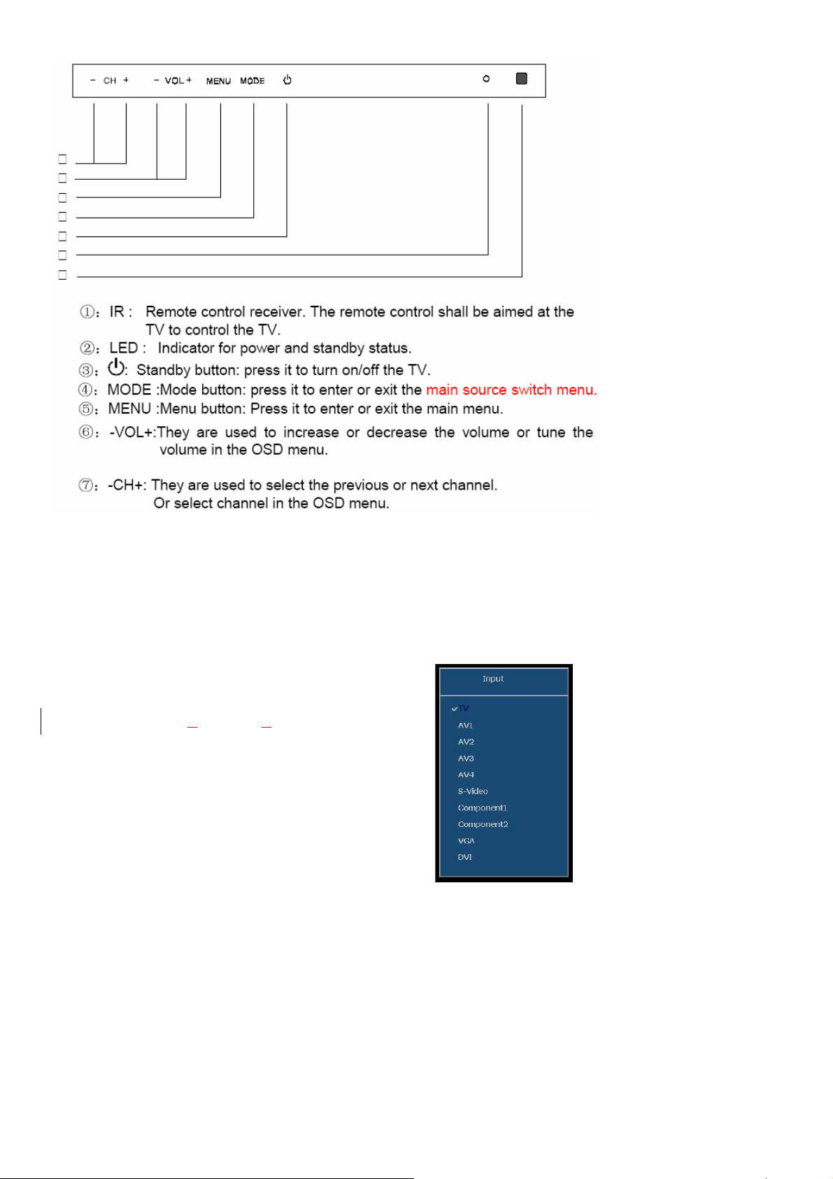
3-3-1 Main Menu
Press the SOURCE button on the remote control to enter the
“SOURCE” Menu. Press “▲▼” to switch among TV, AV1,AV2,
AV3,AV4, S-Video, Com
ponent1/ Component2 , VGA and DVI,
Press “Enter” to enter.
TV:Enter the TV function.
AV1/AV2/AV3/AV4:Enter the Scart or AV function.
S-VIDEO:Enter the S-Video function.
Component1/ Component2:Enter the component video function.
VGA:Enter the VGA mode.
DVI:Enter the DVI mode.
Page 17 of 99
Page 18
Press the Menu button on the remote control or the control panel to enter the main menu. Press “▲▼ ”
button to select “SEARCH” menu, “VIDEO” menu, “AUDIO” menu, “TIME” menu, “SETTING”
menu ,”SCREEN”menu or “PIP”menu.
Press “►” or “ENTER” button to enter the next level submenu, press “EXIT” button close all the
menu.Press “W” or MENU button to previous level submenu .Press “EXIT”colse all the menu.
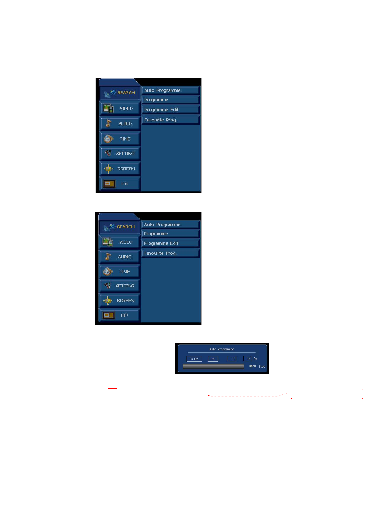
3-3-2 Search Menu
In the SEARCH menu, press “►” or “Enter” to enter submenus.
Auto Programme:Scan all TV channels and store them in the memory automatically.
●Auto Search:Press Menu button to display the main menu.
Press “►” or “Enter” to enter the next level menu, then press
“►” or “Enter” to start automatical searching. Press Exit or
menu button to stop searching.
Programe:to manually search for
a new channel, the current channel will be overwritten by the
searched new channel. For adding a new channel, please set the “storage” to an empty channel, then start
manual searching.
Page 18 of 99
Deleted: a
Page 19
● Storage:the saved serial number of the programme.
● Sound System: Preset TV sound system: D/K、I、B/G 、or L。
● Cable or Air: switch signal among V/UHF、cable.
● Channel No.: to set serial numbers for programs.
● Color System: to select color systems for programs:Auto
● Manual Search: to manually search a new channel, the current channel will be overwritten by the
searched new channel.
Press Menu button to display the main menu, use“
CH+/ CH -” to select a channel. Press “►” or
“Enter”to enter the next level menu, and use “CH+/ CH -” to select “Manual Search”, then press “►” or
“Enter” to start manual searching.
● Fine: to finely tune the current channel to get better images.
● Name:Channel name.
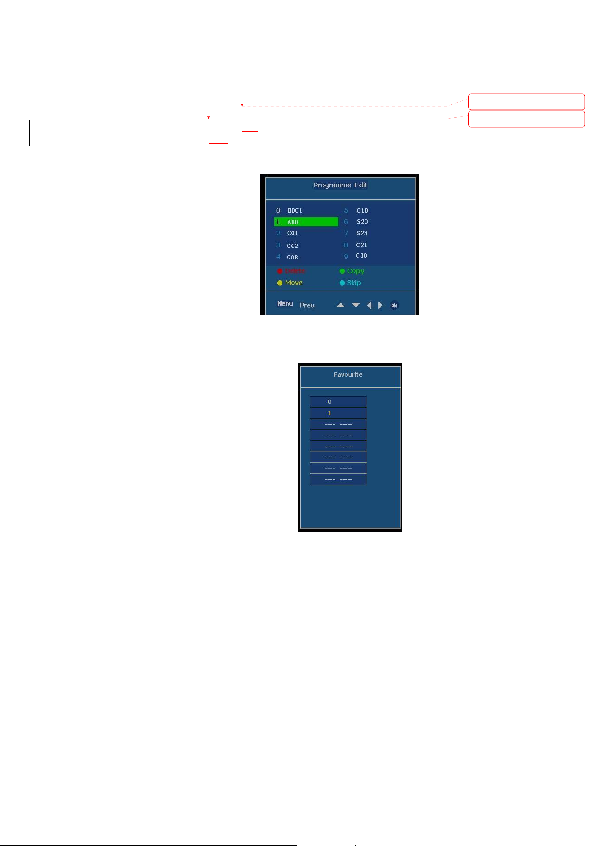
Programme Edit: Press“►” or “Enter”to
Display “To Set”,press
“Enter”into edit. see the
right picture.(Press Red
button on remote control
to delete. Press Green
button to Copy. Press
Yellow button to Move.
Press cyan button to skip
Favourite Prog.:Press “►” or “Enter”enter
Deleted: use “
Deleted: use “
Favorite Menu or Press the
“FAVORITE” button on the
remote control.preset you
the favorite channel number,
press”Enter”to storage.
Press Menu button to display the menu, use “▲▼ ” to select an item. Press “►” or “Enter” to adjust the
value of the selected item. Press Exit to return to the previous level menu and press Menu again to exit the
menu.
Page 19 of 99
Page 20
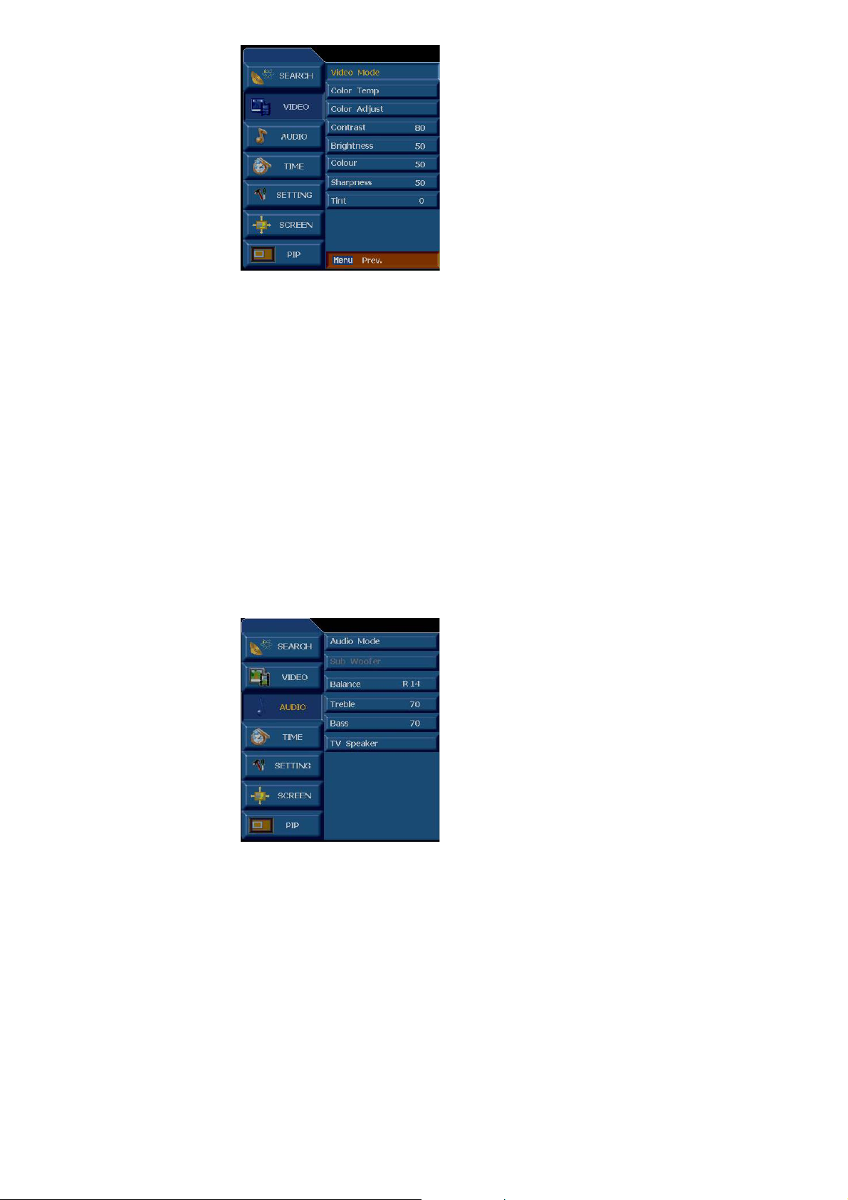
3-3-3 Video Menu
Video Mode: switch picture among Dynamic、Standard、Mild、Game、User。
Color Temp: Color temperature select,Cool、Normal、 Warm 、User、Red、Green、
Blue adjust.
Color Adjust:Set color parameter adjust.
Contrast: To adjust the contrast ratio 0 ~ 100 Adjust
Brightness: To adjust the brightness 0 ~ 100 Adjust
Colour: Color chroma adjust 0 ~ 100 Adjust
Sharpness: To adjust the sharpness, 0 ~ 100 adjust.
Tint: To adjust color phase,to make the image change to red or green (Only for NTSC) 0 ~ 100 Adjust
Press Menu button to display the menu, use “▲▼ ” to select an item. Press “►” or “Enter” to adust the
value of the selected item. Press Exit to return to the previous level menu and press Menu again to exit the
menu.
3-3-4 Audio Menu
Audio Mode: Switch Audio Mode among Flat、Music、Movie、Sports、User.
Subwoof: not supported.
Balance: Adjust the AUDIO level difference between the left and right speakers
Page 20 of 99
Page 21
L50 ~ 0 ~ R50 Adjust
Treble: Adjust the treble sound 0 ~ 100 Adjust
Bass: Adjust the bass sound 0 ~ 100 Adjust
TV Speaker: Switch Internal /External speaker
Press Menu button to display the menu, use
“▲▼ ” to select an item. Press“►” or “Enter” to adjust the
value of the selected item. Press Exit to return to the previous level menu and press Menu again to exit the
menu.
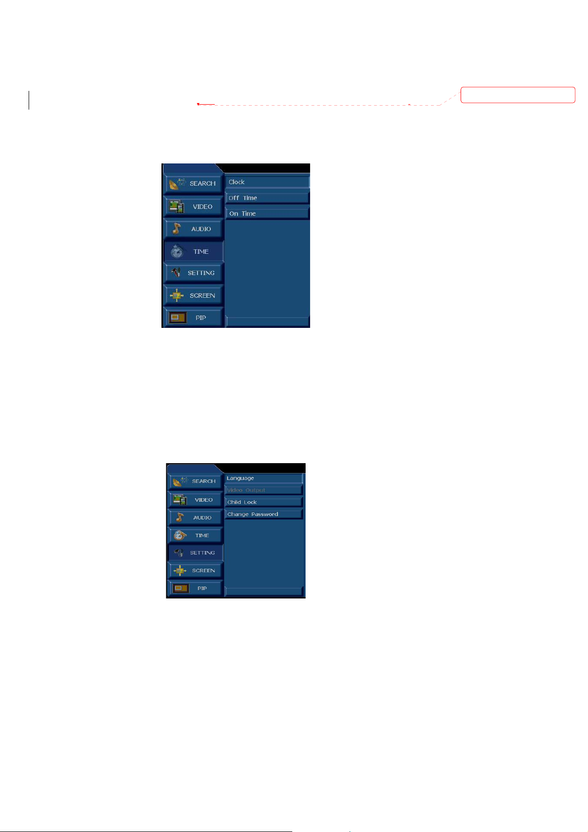
3-3-5 Time Menu
Deleted: use “
Clock: Set the current time.
Off Time: The time for power Off.
ON Time:The channel shall be displayed when power on time is up.
Press Menu button to display the menu, use “▲▼ ” to select an item. Press “►” or “Enter” to adust the
value of the selected item. Press Exit to return to the previous level menu and press Menu again to exit the
menu.
3-3-6 Setting Menu
Language: to select a language for menu: English, Français,Deutsch, Espańol,Italiano.
Video Output: Can not selected.
Page 21 of 99
Page 22
Child Lock: On/ Off lock. Select ON , lock the keypad, at the same time the screen is be blanked,
you must input your password.
Change Password: Need password to change settings,initial Default password is:888888
Press Menu button to display the menu, use “▲▼ ” to select an item. Press “►” or “Enter” to adust the
value of the selected item. Press Exit to return to the previous level menu and press Menu again to exit
the menu.
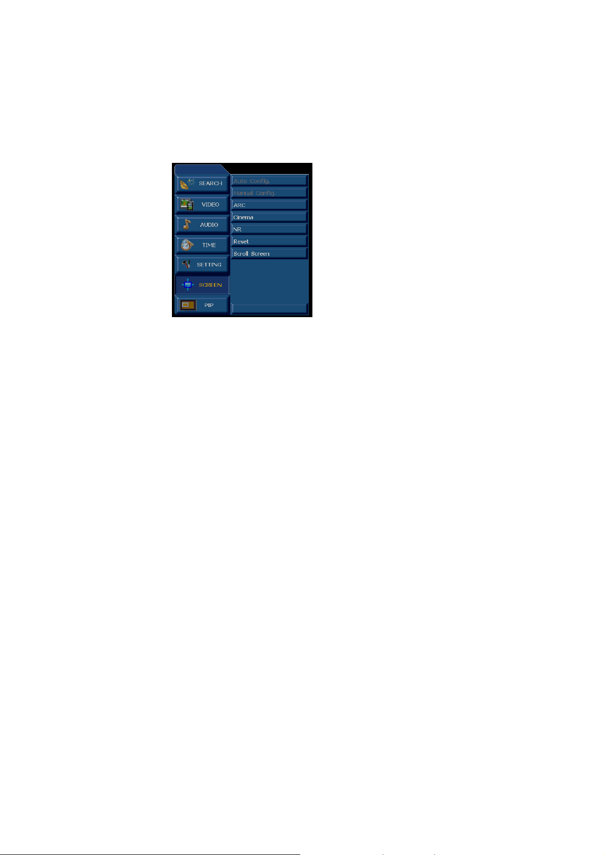
3-3-7 Screen Menu
Auto Config.: Auto adjust the H/V position,H/V size and the phase.
Manual Config.: Manual adjust phase clock and H/V position.
(The above two functions are enabled only when D-SUB.DVI input is used).
ARC: Adjust display ratio(VGA、DVI、 component1/2 are not enabled.
Cinema: ON/OFF 3:2 pull down mode.
NR: Noise reduce adjust 0Æ1Æ2 step.
Reset: Reset default value about the H/V position,H/V size and the phase(just be used
at D-SUB,DVI source.)
Press Menu button to display the menu, use “▲▼ ” to select an item. Press “►” or “Enter” to adust the
value of the selected item. Press Exit to return to the previous level menu and press Menu again to exit
the menu.
Page 22 of 99
Page 23
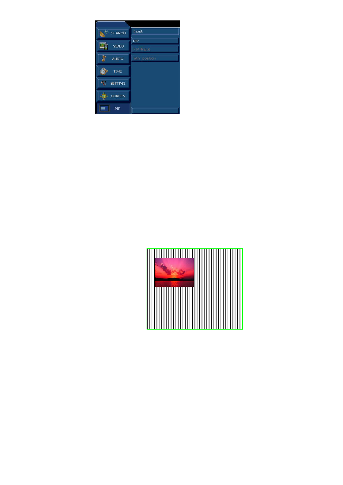
3-3-8 Pip Menu
INPUT: switch main signal among TV, AV1,AV2,AV3,AV4, S-Video, Com
VGA and. DVI.
PIP:Switch the PIP function ON/OFF.
(press the “SWAP”key under the “PIP”situation ,if the main picture can’t be small picture,turn small picture
into the main picture,press the “PIP”key on remote control to enter it .
PIP INPUT: press“W►” select the PIP source or press the “PIP SOUR”key on remote control to swith the
ponent1/ Component2 ,
small picture.
WIN.POSITION:press“W►” select the PIP window position or press the “PIP POS”key on remote control
to move the PIP window.
● PIP: Picture In Picture mode
After entering the PIP mode,the sound will follow
the main picture,user can transmite the sound to sub
picture through press the”***”key to highlight the
PDP mode.
Press“SWAP” key ,user can exchange between the
main and sub picture.
Page 23 of 99
PIP
Page 24
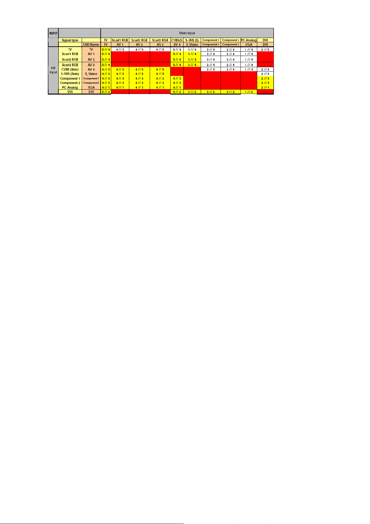
3-8-1-1 PIP Input Mode
3-8-1-2 PIP Function Table List
1 : TRIDENT SCALER PC RGB ANALOG INPUT
2 : TRIDENT SCALER 24 BIT DIGITAL INPUT
3 : TRIDENT SCALER YPbPr ANALOG INPUT
4 : TV SIGNAL AND SCART RGB --> SAA7117 --> 8BIT DIGITAL INPUT
5 : AV SIGNAL --> TRIDENT SCALER AV INPUT PORT
4、Trouble shooting chart
If replace “IMAGE BOARD”, Please re-do “DDC writing” program & “WHITE-BALANCE” & Flash
Update.
If replace PANEL module, Please re-do “white-balance adjust”
4-1 PANEL Trouble shooting
Please reference the “PANEL Service Manual”.
Page 24 of 99
Page 25
4-2 Solution process of MGPC
If change new Image board, it is necessary to refresh DDC and readjust white balance.
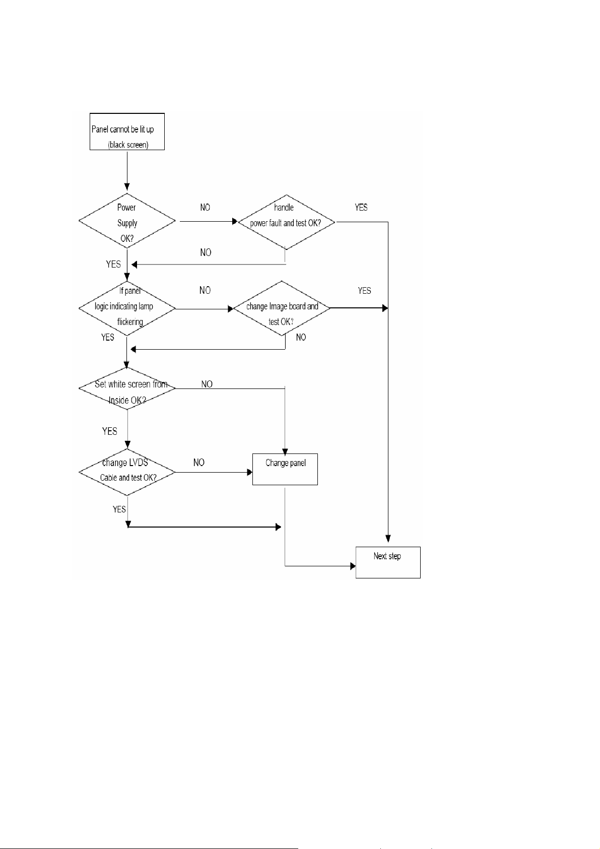
4-2-1 Panel cannot be lit up
4-2-1-1 Check peripheral circuits procedure
Page 25 of 99
Page 26
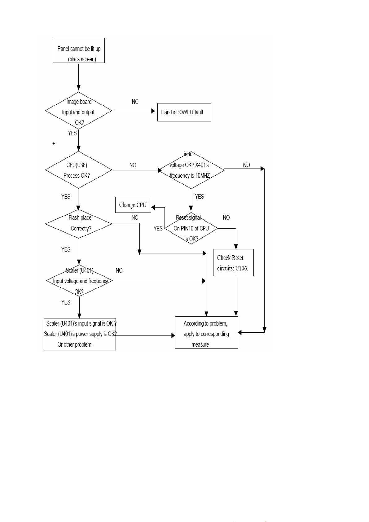
4-2-1-2 Check Image board procedure
Page 26 of 99
Page 27
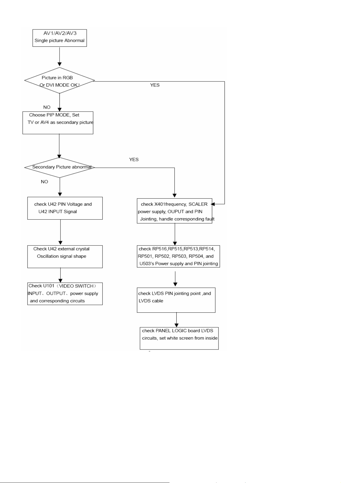
4-2-2 Picture Display --Dynamic picture abnormal
Page 27 of 99
Page 28
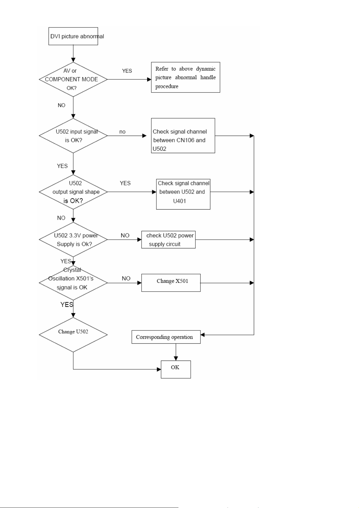
4-2-3 DVI picture abnormal
Page 28 of 99
Page 29
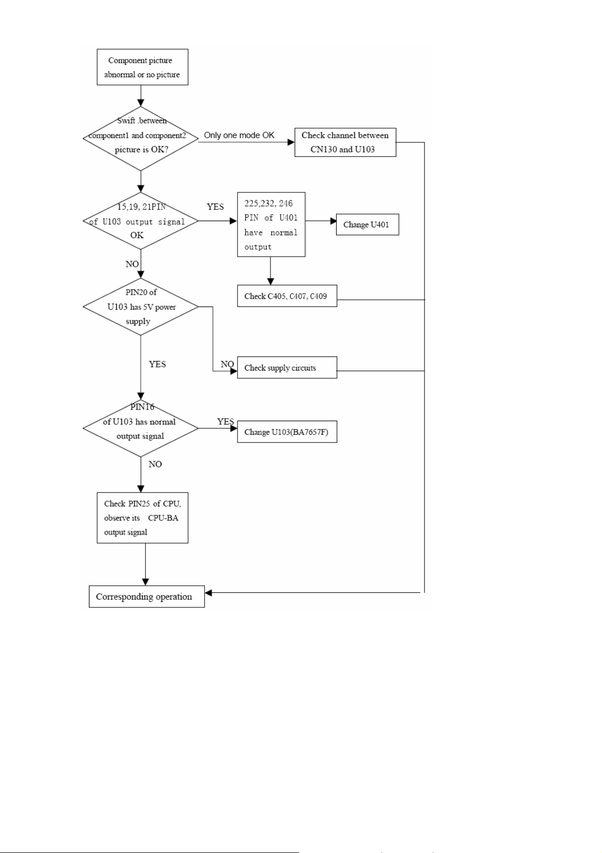
4-2-4 Component picture abnormal
Page 29 of 99
Page 30
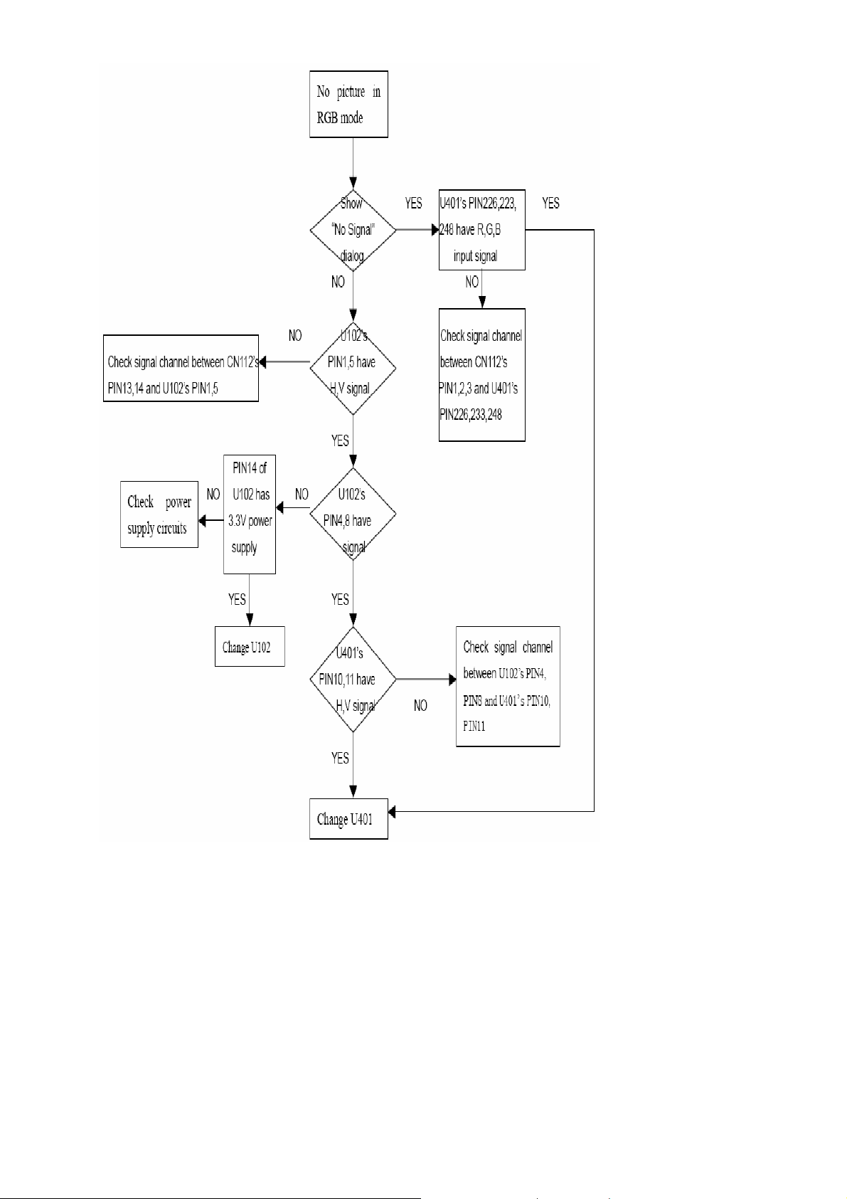
4-2-5 RGB Picture Abnormal
Page 30 of 99
Page 31

4-2-6 Video Picture Abnormal
Page 31 of 99
Page 32

4-2-7 DC Power Supply
Page 32 of 99
Page 33

4-3 TUNER&AUDIO BOARD FAULTS HANDLING
4-3-1 Check DC Power Supply
4-3-2 Tuner Faults Handling
Page 33 of 99
Page 34

4-3-3 Tuner&Audio Board Faults Handling
Page 34 of 99
Page 35

5、White-Balance Adjustment
5-1 Equipments list
Chroma7100 1set
VG828 video signal generator 1set
Chroma-2326 1set
5-2 Preparation and Adjustment process
1、 Preparation:
z Connect rear Video port of PDP with AV port of VG-828.
z Connect component port of PDP with YPbPr port of VG-828
z Connect VGA port of PDP with corresponding port of Chrom2326
z Turn power of PDP and test instrument on.
z Before open lens, Press O-CAL of Chrom-7100 and revise lens.
2、Adjustment process
DVI Mode
1.1 Set Pattern generator to 640X480(60) DVI output and 70% white screen pattern.
1.2 Set OSD picture standard value.
1.3 Used remote control to entry factory mode, adjust Red gain, Green gain, Blue gain value in “white
balance page” and make Chroma 7100 x, y value into color temperature spec and Y value to
maximum. ( Standard: x = 295±10, y = 305±10 )
1.4 Set Pattern generator to 640X480(60) DVI output and 32 Gray scale pattern.
1.5 Used remote control to entry factory mode, adjust Green offset value and Green gain value in
“white balance page” to make 32 gray scale pattern can be distinguished 28 gray scale at least,
and the most darkness level is totally dark, and make sure the most brightness two level can be
distinguished
1.6 Set Pattern generator to 640X480(60) DVI output and 20% white screen pattern.
1.7 Used remote control to entry factory mode, adjust Red offset, Blue offset value in “white
balance page” and make Chroma 7100 x, y value into color temperature spec (Standard: x = 295
±10, y = 305±10)
1.8 Repeat step 1.3 to 1.7 until 70% & 20% white screen pattern x, y value in spec.
RGB Mode:
1.1 Set Pattern generator to 640X480(60) VGA output and 70% white screen pattern.
1.2 Set OSD picture standard value.
1.3 Used remote control to entry factory mode, adjust Red gain, Green gain, Blue gain value in “white
Page 35 of 99
Page 36

balance page” and make Chroma 7100 x, y value into color temperature spec and Y value to
maximum. ( Standard: x = 295±10, y = 305±10 )
1.4 Set Pattern generator to 640X480(60) VGA output and 32 Gray scale pattern.
1.5 Used remote control to entry factory mode, adjust Green offset value and Green gain value in
“white balance page” to make 32 gray scale pattern can be distinguished 28 gray scale at least,
and the most darkness level is totally dark, and make sure the most brightness two level can be
distinguished
1.6 Set Pattern generator to 640X480(60) VGA output and 20% white screen pattern.
1.7 Used remote control to entry factory mode, adjust Red offset, Blue offset value in “white balance
page” and make Chroma 7100 x, y value into color temperature spec (Standard: x = 295±10, y
= 305±10)
1.8 Repeat step 2.3 to 2.7 until 70% & 20% white screen pattern x, y value in spec.
Component mode:
1.9 4.1 Set Pattern generator to 480P Component output and 70% white screen pattern.
1.10 Set OSD picture standard value.
1.11 Used remote control to entry factory mode, adjust Red gain, Green gain, Blue gain value in “white
balance page” and make Chroma 7100 x, y value into color temperature spec and Y value to
maximum. ( Standard: x = 295±10, y = 305±10 )
1.12 Set Pattern generator to 480P Component and 32 Gray scale pattern.
1.13 Used remote control to entry factory mode, adjust Green offset value and Green gain value in
“white balance page” to make 32 gray scale pattern can be distinguished 28 gray scale at least,
and the most darkness level is totally dark, and make sure the most brightness two level can be
distinguished
1.14 Set Pattern generator to 480P Component output and 20% white screen pattern.
1.15 Used remote control to entry factory mode, adjust Red offset, Blue offset value in “white balance
page” and make Chroma 7100 x, y value into color temperature spec (Standard: x = 295±10, y
= 305±10)
1.16 Repeat step 4.3 to 4.7 until 70% & 20% white screen pattern x, y value in spec.
Video mode:
1.17 4.1 Set Pattern generator to PAL output and 70% white screen pattern.
1.18 Set OSD picture standard value.
1.19 Used remote control to entry factory mode, adjust Red gain, Green gain, Blue gain value in “white
balance page” and make Chroma 7100 x, y value into color temperature spec and Y value to
Page 36 of 99
Page 37

maximum. ( Standard: x = 295±10, y = 305±10 )
1.20 Set Pattern generator to PAL output and 32 Gray scale pattern.
1.21 Used remote control to entry factory mode, adjust Green offset value and Green gain value in
“white balance page” to make 32 gray scale pattern can be distinguished 28 gray scale at least,
and the most darkness level is totally dark, and make sure the most brightness two level can be
distinguished
1.22 Set Pattern generator to PAL output and 20% white screen pattern.
1.23 Used remote control to entry factory mode, adjust Red offset, Blue offset value “white balance
page” and make Chroma 7100 x, y value into color temperature spec (Standard: x = 295±10, y
= 305±10)
1.24 Repeat step 4.3 to 4.7 until 70% & 20% white screen pattern x, y value in spec.
6、DDC program and test
6-1 Equipments list and prepare
DDC tester 1PCS
PC 1SET
D-SUB cable 1PCS
DVI cable 1PCS
Barcode Reader 1SET
Prepare before test:
1. Turn on the power of your PC and programmer, then make good connection of them.
2. Connect the D-SUB wire and DVI wire to the DDC program equipment and the PDP monitor.
6-2 Program and test process
1. Choose different DDC menu according to different customer , do use PAGE DOWN/PAGE UP to go to
the submenu and parent menu until find the right model. Press enter to access the program interface.
There will be shown RGB on the screen. Then switch to RGB program on the DDC connector。Press
any key to access RGB program interface ,then there will be “input serial no.:” prompt on the screen.
2. Use Bar Readers to read the serial no to the program,then make sure the serial no you have read is the
same as on the barcode. Then set the PDP to blue screen mode, press enter to start.
3. Watch the information of the program, it means programmed OK when the following interface come out.
please CHECK Manufacturer Name、Vendor Assigned Code、Model Name、Serial Number:
****[?????????****](same as Barcode)、Week of Manufacture:**、Year of Manufacture:****、
Checksum:**(same as the last byte of data table, reference to the note of RGB programming picture)
and so on.
4. Press Enter to access RGB DDC test interface,follow the DDC test picture,CHECK Manufacturer
Name、Vendor Assigned Code、Model Name、Serial Number:****[?????????****](same as Barcode)、
Week of Manufacture:**、Year of Manufacture ****、Video Input:Analog、Checksum
:**(same as
the last byte of data table, reference to the note of RGB programming picture)and so on.
5. Press any key to access DVI program interface, there will be “DVI” shown on the screen. Switch
the of switch on the DDC connector, press any key to access DVI program interface, there will be
Page 37 of 99
Page 38

“input serial no.:” promote.
6. Use Bar Readers to read the serial no to the program,then make sure the serial no you have read is the
same as on the barcode. Then set the PDP to blue screen mode, press enter to start.
7. Watch the information of the program, it means programmed OK when the following interface come out.
please CHECK Manufacturer Name、Vendor Assigned Code、Model Name、Serial Number:
****[?????????****](same as Barcode)、Week of Manufacture:**、Year of Manufacture:****、
Checksum:**(same as the last byte of data table, reference to the note of DVI programming picture)
and so on.
8. Press Enter to access DVI DDC test interface,follow the DDC test picture,CHECK Manufacturer
Name、Vendor Assigned Code、Model Name、Serial Number:****[?????????****](same as Barcode)、
Week of Manufacture:**、Year of Manufacture ****、Video Input:Analog、Checksum:**(same as
the last byte of data table, reference to the note of DVI programming picture)and so on。If the recording
is failure, check the connection of equipment and record again from the step4.If all of these work does
not take work ,please ask IE department for help.
Notice :the “?” and “*” symbol will be changed according to the year of manufacture ,and so on.
7、Flash Update
7-1 The list of Instrument
1、 Prepare 1 piece of RS232 cable(Th e Pin connection see the Figure-1,If difference, please re-connect the
cable)and 1 set of PC.
2、 Connect the RS232 cable with PC and PDP(See the Figure-2).
TO PC TO ACER PDP
9PIN (Female) 9PIN (Female)
Signal Pin Signal Pin
1 1 NC
RXD 2 2 TXD transmitted date
TXD 3 3 RXD received date
DTR 4 4 NC
GND 5 5 FG frame ground
DSR 6 6 NC
RTS 7 7 NC
CTS 8 8 NC
9 9 NC
Figure-1
7-2 The operation explaining Flash Update
Note: Operation Under the situation of PDP working normally.
1. Find ISPWriter2.exe file
in the screen of computer, dblclick it
2. Enter the window, click OPEN,then click LINK.(Like figure 1)
Page 38 of 99
Page 39

3. Press the AC power switch. It will show the duologue window when PDP and PC connect correct. LED is
red(If the connect is not correct,it will retain like figure 1,and the PDP will open, LED is blue ) press
“confirm”;
figure 2
4. Click config key, will show duologue window like figure 3:choose the type of Flash at Chip duologue
window, if the chip is AMIC ,it will choose MX29LV040,SST should be choose SST29SF040,other
option should the same with picture. Then click OK key;
figure 3
5. Click BIN, it will show duologue window as picture 4 ,choose the *.bin file ,click open key
figure 4
Page 39 of 99
Page 40

5. Click the Prog key , it will show duologue window as picture 5 ,it start to write he soft ware ,
6.
RE: It will use about 3 minute to write soft ware, Do not turn-off the PDP during that time;
otherwise it will make the Flash IC break.
figure 5
7. Finish writing, it will show duologue window as picture 6, it mean end, click OK.
Clicking DELINK key .then CLOSE key exit the programme.
figure 6
8. Turn-off the PDP. Pull out RS232 wire. then turn-on the PDP and enter factory menu,watch the edition of
soft ware whether or not the same with edition of writing.
Page 40 of 99
Page 41

8、Software Administer Block diagram
8-1 Main Block diagram (Kernel part)
Page 41 of 99
Page 42

8-2 SOURCE key Block diagram
ucCurrentMainMenuID=t_TOE.ucMenuID
_VK_AV/TV_
ProcessCommand
tvAppSetOSD
toeLoadOSDItems (DirectMenus)
tdSetSysTimer
tdClearSysTimer
bDirectMenu=_TRUE_
toeInvokeMenu4
toeDrawOSDMenu2
toeUserDrawOSDMenu
toeResetMenuStatus
Page 42 of 99
Page 43

8-3 MENU key Block diagram
toeUserGetPersistentItemValue
_VK_MENU_
ProcessCommand
tvAppSetOSD
tdSetSysTimer
tdClearSysTimer
bMainMenu=_TRUE_
bEEpromOnline?
toeUserGetPersistentItemValue
Page 43 of 99
Page 44

8-4 Mode Check Block diagram
Page 44 of 99
Page 45

8-5 SCART Key Choose Process
ProcessCommand
Page 45 of 99
Page 46

NeedUpdataOSD
clearSysTimer(_OSDTIMER_)
toeLoadOSDItems
Y
bNeedUpdateOSD?
N
Y
NoSignal ||
UnKnowSignal
N
N
NeedClearTimer
Y
ClearSysTimer(_SOUNDINFO_)
N
MPSourceIsScart
Y
N
ScartSourcebak
!= MPSource
Y
ScartSourcebak = MPSource
N
PoweronStart
ShowXDDemo(_TRUE_)
ShowNoSingal
Page 46 of 99
Page 47

Y
ShowProgramStatus
SetSysTimer
TranslateTeletextKey
N
tdCommandTT
Y
N
GetTTSysState !=
_TT_STATE_TEXT_
Y
AppSetOSD
N
IsRealKey
Y
N
AutoSleepTimer
Y
N
NeedBlackScreen
Y
AutoSleepTimer = AUTOSLEEP_SECOND
AutoSleepTimer = 0
g_Timer.w2HourOff = 0
Page 47 of 99
Page 48

_)
NeedUpdateOSD = _FALSE_
SortShowInfo = g_Data.bShowInfo
NeedClearTimer = _TRUE_
N
VirtualKey !=
_VK_NOSIGNAL_
Y
ClearSysTimer(_XDDEMOTIMER
ShowInfo = _TRUE_
N
!ShowProgramStatus
&& !ShowSoundStatus
Y
ShowProgramStatus
NeedClearTimer = _FALSE_
SetSysTimer
N
!g_Data.bShowSoundStatus
Y
ShowSoundInfo
SetSysTimer
ProcessCommand(ucVirtualKey)
Page 48 of 99
Page 49

9、Block diagram & Explain
9-1 PDP block diagram and functions
9
IR/B
NOTICE:
1.Panel P9Z1 TO PANEL CN8001 Power Input Cable.
2.Panel CN8004 TO MGPC CN120 MGPC Power
3.Panel CN8007 TO MGPC CN121&TUPC CN183 MGPC Power&TUPC Power
4.MGPC JP12 to TUPC JP182 MGPC to TUPC Signal
5. MGPC JP13 to TUPC JP183 MGPC to TUPC Signal
6.MGPC CN127 TO TMPC CN127 S-Video & Video Signal
7.TUPC CN670 to TMPC CN210 Video Channel Sound
8.TUPC J602 to AUPC H5Z1 Extrenal Speaker
9.MGPC CN114 to IR P201& KEPC P202 IR&Key
Function of Board:
1) IMAGE Board : Control all input signals, Decode the video signal, De-interlace, and
send digital signals (LVDS signal) sent from image Board and display
2) PDC Board: Power Down Control Board
3) SIDE AV Board: The input signal interface
4) Power Board: Supply Power for Panel and Image Board
5) KEY Board: POWER, Signal Source, MENU, CH+, CH - / VOL +, VOL -
6) Power ON /OFF: Turn power on/off
MGPC
2
KEPC
6
Panel
PSPC
TUPC
7
TMPC
8
AUPC
Page 49 of 99
Page 50

9-2 Image board block diagram and signal introduce
9-2-1 Image board block diagram
Main Board
LVDS
SCL
SDA
ROM
M16C
RS232
RS232
4Mx32
DDR
SVP_EX52
24bit
Sil9011
S-Video
From side board
DVI PC/RGB
Audio DVI/PC
CN127
Y Pb Pr
8bit
PIP Decode
Main AV
BA7657F
Video
Audio DVI
Audio PC
SAA7117A
PIP AV
U112
4052
SW3
SW4
P2 L/R
MainTV
PipTV
SCART2/3
SCART1
AOUT_R/L
CVBS_2_T
SW6
SW7
SW8
8V_AU
5V_SB
P1 L/R
SW11
SW1
SW2
Y2
Y1
MENUSource
P- P+V+V-
Page 50 of 99
Pb2
Pb Pr
Pr2
L4R3R4
L3
Page 51

9-2-2 Input signal introduce
1. VIDEO: transmit bright & chroma signal , it is general ,its picture quality is equal to the general
VCD.S-VIDEO transmit the bright and the chroma single, and can reduce/control the cross-interfere , it
is better than the Video.
2. RGB&D-SUB(Pc interface ): general RGB simulative input interface .
3. YCbCr(NTSC/PAL): is composed of one bright and two chromatism signals U/V. due to the eye is
more sensitive for bright than chroma , RGB via the formulae Y=0.39R+0.50G+0.11B to transform into
one bright and two chromatism signals U(R-Y), V(B-Y).
4. VIDEO、S-VIDEO、YCBCR: the frequency 15.6KHZ 50(PAL)/60HZ(NTSC), interleaved simulative
signal.
5. YPbPr: non-interlaced signal, belong to DTV scope, support 480P,720P,1080i format, current is
NTSC.
6. DVI:digital Visual Interface, has 29pin(DVI-I)and 25pin (DVI-D), now many top grade display card
own it.
9-3 TUNER board block diagram
TUNER BOARD
SCL
SDA
MainTV
PipTV
SCART2/3-RGBVFA
SCART1-RGBVFA
TEA6415
SW6
SW7
SW8
8V_AU
5V_SB
SW11
SW1
SW2
S1_Y
S2_Y
S3_Y
SCART1_VOUT
Q_LINK1
SCART1 SCART3SCART2
MainTV
PipTV
SCART1_VOUT
AUDIO4
CVBS_OUT
CN670
MSP3450
AUDIO2
74LV4052
AV-S-R/L
SCART1-R/L
SCART2-R/L
Q_LINK2
SW7
SCART3-R/L
AV_TV
SW8
SCART2_VOUT
TVMAIN_SIF
TA2024
SW6
QS3257
QS3257
SCART2-RGBVFA
SCART3-RGBVFA
Q_LINK3
SP CON
TL072CD
Main tuner
VIDEO/S_VIDEO
S
AUDIO R/L
L
R
V
Earphone
Page 51 of 99
Page 52

10、Waveform of signal
10-1 Waveform of input signal
YCbCr:Timing946 Pattern946 color bar picture YCbCr:Timing946 Pattern946 color bar picture
Y Luminance Signal Red Signal
YCbCr:Timing946 Pattern946 color bar picture YCbCr:Timing 949 Pattern936 Full White Picture
Blue Signal Y Luminance Signal
YCbCr:Timing 949 Pattern921 Gray Picture
Page 52 of 99
Page 53

YPBPR
YPbPr:Timing955 Pattern946 color bar picture YPbPr:Timing955 Pattern946 color bar picture
Y Luminance Signal Red Signal
YPbPr:Timing955 Pattern946 Color bar picture
Blue Signal
YPbPr:Timing953 Pattern921 Gray Picture YPbPr:Timing954 Pattern936 Full White Picture
Page 53 of 99
Page 54

VIDEO
Video:Timing946 Pattern946 Color bar picture Video:Timing949 Pattern936 Full White Picture
S—VIDEO
Video:Timing949 Pattern921 Gray Picture S-video:Timing946 Patern946 Color bar picture
S-video:Timing949 Pattern936 Full White Picture S-video:Timing949 Pattern921 Gray Picture
Page 54 of 99
Page 55

10-2 Signal waveform in the image board
·VIDEO
Video:Timing946 Pattern946 Color bar picture Video:Timing946 Pattern946 Color bar picture U 6 0 2
separate)In pin88、Q602 E rank U602(Y/C separate)Out pin84U611 In pin73
(Y/C
Video:Timing 949 Pattern936 Full White Picture Video:Timing 949 Pattern936 Full White Picture
U602(Y/C
separate)In pin88、Q602 E rank U602(Y/C separate)Out pin84U611 In pin73
Video:Timing 949 Pattern936 Full White Picture Video:Timing 949 Pattern921 Gray Picture
Decoder
output 8bit digital signal U602(Y/C separate)In pin88、Q602 E极
Page 55 of 99
Page 56

Video:Timing 949 Pattern921 Gray Picture Video:Timing 949 Pattern921 Gray Picture
U602(Y/C
separate)Outpin84 U611 In pin73 U611 Decoder output 8bit digital signal
·S—VIDEO
S-Video:Timing 946 Pattern946 Color bar picture S-Video:Timing 946 Pattern946 Color bar picture
U600 pin5 Q600 E rank U600 PIN18 U602 pin88
S-Video:Timing 946 Pattern946
U602 pin84 U611 pin73 U611
Color bar picture S-Video:Timing 949 Pattern946 Color bar picture
output 8bit digital signal
Page 56 of 99
Page 57

S-Video:Timing 949 Pattern936 Full White Picture S-Video:Timing 949 Pattern936 Full White Picture
U600 pin5 Q600 E rank U600 pin18 U602 pin88
S-Video:Timing 949 Pattern936 Full White Picture S-Video:Timing 949 Pattern921 Gray Picture
U602 pin84 U611 pin73 U600 pin5 Q600 E rank
S-Video:Timing 949 Pattern921 Gray Picture S-Video:Timing 949 Pattern921 Gray Picture
U600 pin18 U602 pin88 U602 pin84 U611pin73
Page 57 of 99
Page 58

YCBCR
YCbCr:Timing946 Pattern946 Color bar picture YCbCr:Timing 946 Pattern946 Color bar picture
Y Signal --L618 R Signal—L619
YCbCr:Timing 946 Pattern946 Color bar picture YCbCr:Timing 949 Pattern936 Full White Picture
B Signal—L617 Y Signal—L618
YCbCr:Timing 949 Pattern936 Full White Picture YCbCr:Timing 949 Pattern921 Gray Picture
R/B Signal—L619/L617 Y Signal—L618
Page 58 of 99
Page 59

YCbCr:Timing 949 Pattern921 Gray Picture YCbCr:Timing 949、946 Pattern921、936、94 Gray
Picture/ Color bar picture/ Full White Picture
R/B—L619/L617 Signal Decoder
YPBPR
YPbPr:Timing 955 PATTERN946 Color bar picture YPbPr:Timing 955 Pattern946 Color bar picture
Y Signal—L611 R Signal—L612
output 8bit digital signal
YPbPr:Timing 955 Pattern946 Color bar picture YPbPr:Timing 954 Pattern936 Full White Picture
B Signal—L610 Y Signal—L611
Page 59 of 99
Page 60

YPbPr:Timing 954 Pattern936 Full White Picture YPbPr:Timing 953 Pattern921 Gray Picture
R/B Signal—L612/L610 Y Signal—L611
YPbPr:Timing 953 Pattern921 Gray Picture
R/B Signal—L612/L610
R/G/B
RGB:Timing4 Pattern101 Pane Picture RGB:Timing4 Pattern101 Pane Picture
R—FL700 Waveform G—FL701 Waveform
Page 60 of 99
Page 61

RGB:Timing4 Pattern101 Pane Picture RGB:Timing4 Pattern101 Pane Picture
B—FL702 Waveform H—FL704 Waveform
RGB:Timing4 Pattern101 Pane Picture RGB::Timing4 Pattern105 Full White Picture
V—FL705 Waveform RGB—FL700/701/702 Waveform
RGB:Timing4 Pattern105 Full White Picture RGB:Timing4 Pattern105 Full White Picture
H—FL704 Waveform V—FL705 Waveform
Page 61 of 99
Page 62

RGB:Timing172 Pattern105 Window Picture RGB:Timing172 Pattern105 Window Picture
R—FL700 Waveform G—FL701 Waveform
RGB:Timing172 Pattern105 Window Picture RGB:Timing172 Pattern105 Window Picture
B—FL702 Waveform H—FL704 Waveform
RGB:Timing172 Pattern105 Window Picture RGB:Timing4 Pattern27 Color bar picture
V—FL705 Waveform R—FL700 Waveform
Page 62 of 99
Page 63

RGB:Timing4 Pattern27 Color bar picture RGB:Timing4 Pattern27 Color bar picture
G—FL701 Waveform B—FL702 Waveform
RGB:Timing4 Pattern27 Color bar picture RGB:Timing4 Pattern27 Color bar picture
H—FL704 Waveform V—FL705 Waveform
Page 63 of 99
Page 64

11、Check and Measure
11-1 Image board
Test the power of each chip with the universal meter, to ground impedance and earth
situation.
11-1-1 Power Check and Measure
A
B C D
Supply with getting red arrow point A/B/C/D that identification come out for power, image of board with the
interface among having picture, it corresponding power make detection method separately among following
several picture.
①. In the following tht picture it is successively 1pin to 5 pin of CN121 from left to right, Among them, 1pin
connect 6V voltage and 3pin connect 12V;2pin and 4pin connect power,5pin no connect.
NOTICE:This Picture For SDI Panel Power
Page 64 of 99
Page 65

②. In the following picture it is suc cessively 1 to 11 pin of CN120 from left to right. Among them,
The second pin connects STB5V and supplied the power of CPU U38,this voltage is direct provide Panel
Powre Board when turn on the PDP,And this is first reason for CPU normally working,4pin is
Relay on signal output,5pin connect D12V,8pin and 9pin connect 3.3V power,11pin connect D6V
Power,1pin no connect,3pin/6pin/7pin connect GND.
NOTICE:This Picture For SDI Panel Power
③. In the following picture it is successively 1 to 7 pin of CN123 from left to right,1pin ACD siganl output ,2pin
Relay on signal output,3pin connect STB5V and this is provide power for CPU U38, this voltage is direct
provide Panel Powre Board when turn on the PDP,And this is first reason for CPU normally working,4pin
connect GND,5pin connect VS-ON signal output,6pin conncet 5V power,7pin no connect.
NOTICE:This Picture For LG Panel Power
④.In the following picture it is successively 1 to 7 pin of CN123 from left to right,1pin and 2pin connect
9VSC,3pin/7pin/8pin/9pin connect GND,4pin/5pin/6pin connect 5VSC power.
NOTICE:This Picture For LG Panel Power
11-1-2 Voltage value of IC necessary
电压值 对应的 IC 的点位及其引脚
STB5V U38(M30620SPGP)Pin(96,97)
U101(AZ1117-33) Pin 3
+3.3VP NC
D6V/5VSC U701(AP1084D-ADJ) Pin 3
U702(AP1084K33) Pin 3
U703(AP1084D-ADJ) Pin 3
U704(AP1084K33) Pin 3
U708(AP1084K33) Pin 3
U201(MSP3450G) Pin63
9VSC NC
Page 65 of 99
Page 66

D12V U107(AZ1117) Pin 3
11-2 AUDIO and TUNER Board CHECK
U605(TA2024) Pin24.25.29.30.33
In the top picture it is provide Audio/Tuner Board Audio Amp power,Among them,1pin and 2pin connect
12V,3pin/4pin/6pin connect GND,5pin no connect.PLS consult nether oicture:
Page 66 of 99
Page 67

12、Mechanical Introduction
buffer
buffer
12-1 PDP Internal view
SMPS
X-main
Logic F
Image Borad Tunner Board
Y-main
Logic E
(lower)
Y-buffe
(upper)
Y-buffe
Page 67 of 99
Page 68

Page 69

12-2 Mechanical of cabinet front disassembly
Page 69 of 99
Page 70

12-3 Disassembly and assembly
12-3-1 PDP stand removal
1
1) Unplug the AC power and all signal cables.
2 3
2) Place the PDP upside down on a tabletop (use a protection sheet or EPE bag), Take care, that this
is flat and free from obstacles like screws, to prevent damaging the fragile PDP glass filter (1).
3) Remove the four black colored screws around the stand holder (2).
4) Remove the Base assembly from PDP as the direction arrowhead showed (3).
Page 70 of 99
Page 71

12-3-2 Back Cover Removal
3
1
2
1). Remove the six big black colored screws in the panel holder as the red-circle showed (1).
2) .Remove the eleven black colored screws around the terminals as the green-pane showed (2).
3) .Remove the twerty-nine black colored screws around the back cover as the blue-pane showed (3).
4) .Carefully prize up the back cover from the left of the PDP (5).
5) .Carefully remove the Back Cover from the top of the PDP, and store in a safe place.
Page 71 of 99
Page 72

12-3-3 Rear Low Cover removal
1). Carefully use a allen screwdriver to remove the six silver colored allen screws M3*6mm (1).
2) .Remove the five black screws(2).
3).Remove the TUNER connect (3).
4).After remove the TUNER connect(4).
5).Remove the Rear Low Cover as the direction arrowhead showed (5).
Page 72 of 99
Page 73

6). The Rear Low Cover done(6)
6
12-3-4 Main Board(MGPC) and TUNER AUDIO Board (TUPC)removal
1
2
1). Disconnect the all connectors(green circularity).
2) Remove the six silver screws from MGPC(main board)(1) and romove six silver from TUPC(2).
MGPC plate
3) Remove the MGPC board from PCB plate. 4).Done
Page 73 of 99
Page 74

12-3-5 PCB Plate Removal
2
1
PCB plate
1). Remove the two Cable Clips from the PCB Plate(2)
2) .Remove the four sliver screws(1).
3). Remove the PCB Plate
12-3-6 Key Board Remove
1
1) Remove the four silver screws(1).
2). Pull the Bezel downside(2), then push and take out the KEY board assembly(3).
Page 74 of 99
Page 75

3). Remove the five silver screws to disassemble the key board from Key button.
12-3-7 Side AV Board Removal
2
1
1) .Remove the two silver screws (1).
2). Remove the side cover from Side AV board(2)
3). Disconnect the blue circularity from Side AV board.
4). Remove the four silver screws (3).
3
Page 75 of 99
Page 76

12-3-8 Panel Module Removal
1) .Remove the four silver screw around the PANEL corner (1).
2).Remove all the aluminum foil around the panel (2), after assemble the new panel, must re-affix the
aluminum foil, if it’s broken must change a new one, otherwise, the EMI can be affected.
3). Two people hold the panel holder 1 and 2 respectively, then uplift the panel module and move it out
form the front cover(Bezel), and store in a safe place.
Page 76 of 99
Page 77

12-4 Panel Wiring diagram
Page 77 of 99
Page 78

13、PCB LAYOUT
13-1 Image broad PCB LAYOUT
PASTE MASK TOP
Page 78 of 99
Page 79

PASTE MASK BOTTOM
Page 79 of 99
Page 80

13-2 TUNER board and AUDIO board PCB LAYOUT
TOP
Page 80 of 99
Page 81

BOTTOM
Page 81 of 99
Page 82

14、Schematic diagram
Page 82 of 99
Page 83

Page 83 of 99
Page 84

Page 84 of 99
Page 85

Page 85 of 99
Page 86

Page 86 of 99
Page 87

Page 87 of 99
Page 88

Page 88 of 99
Page 89

Page 89 of 99
Page 90

Page 90 of 99
Page 91

Page 91 of 99
Page 92

Page 92 of 99
Page 93

Page 93 of 99
Page 94

Page 94 of 99
Page 95

Page 95 of 99
Page 96

Page 96 of 99
Page 97

Page 97 of 99
Page 98

Page 98 of 99
Page 99

Page 99 of 99
 Loading...