

Page 1

AT3705
Service Guide
Service guide files and updates are available
on the AIPG/CSD web; for more information,
please refer to http://csd.acer.com.tw
PRINTED IN TAIWAN
Page 2

Revision History
Please refer to the table below for the updates made on AT3705 service guide.
Date Chapter Updates
II
Page 3

Copyright
Copyright © 2005 by Acer Incorporated. All rights reserved. No part of this publication may be reproduced,
transmitted, transcribed, stored in a retrieval system, or translated into any language or computer language, in
any form or by any means, electronic, mechanical, magnetic, optical, chemical, manual or otherwise, without
the prior written permission of Acer Incorporated.
Disclaimer
The information in this guide is subject to change without notice.
Acer Incorporated makes no representations or warranties, either expressed or implied, with respect to the
contents hereof and specifically disclaims any warranties of merchantability or fitness for any particular
purpose. Any Acer Incorporated software described in this manual is sold or licensed "as is". Should the
programs prove defective following their purchase, the buyer (and not Acer Incorporated, its distributor, or its
dealer) assumes the entire cost of all necessary servicing, repair, and any incidental or consequential
damages resulting from any defect in the software.
Acer is a registered trademark of Acer Corporation.
Intel is a registered trademark of Intel Corporation.
Other brand and product names are trademarks and/or registered trademarks of their respective holders.
III
Page 4
Conventions
The following conventions are used in this manual:
Screen messages
NOTE Gives bits and pieces of additional
WARNING Alerts you to any damage that might
CAUTION Gives precautionary measures to
IMPORTANT Reminds you to do specific actions
Denotes actual messages that appear
on screen.
information related to the current
topic.
result from doing or not doing specific
actions.
avoid possible hardware or software
problems.
relevant to the accomplishment of
procedures.
IV
Page 5

Preface
Before using this information and the product it supports, please read the following general information.
1. This Service Guide provides you with all technical information relating to the BASIC CONFIGURATION
decided for Acer's "global" product offering. To better fit local market requirements and enhance product
competitiveness, your regional office MAY have decided to extend the functionality of a machine (e.g.
add-on card, modem, or extra memory capability). These LOCALIZED FEATURES will NOT be covered
in this generic service guide. In such cases, please contact your regional offices or the responsible
personnel/channel to provide you with further technical details.
2. Please note WHEN ORDERING FRU PARTS, that you should check the most up-to-date information
available on your regional web or channel. If, for whatever reason, a part number change is made, it will
not be noted in the printed Service Guide. For ACER-AUTHORIZED SERVICE PROVIDERS, your Acer
office may have a DIFFERENT part number code to those given in the FRU list of this printed Service
Guide. You MUST use the list provided by your regional Acer office to order FRU parts for repair and
service of customer machines.
V
Page 6

Chapter1 System Specifications ...............................................1
Introduction . . . . . . . . . . . . . . . . . . . . . . . . . . . . . . . . . . . . . . . 1
Chapter3 Machine Disassembly and Replacement ............32
General Information . . . . . . . . . . . . . . . . . . . . . . . . . . . . . . . 33
Disassembly Procedure . . . . . . . . . . . . . . . . . . . . . . . . . . . . 34
Chapter 4 Troubleshooting.........................................................50
Chapter 6 FRU (Field Replaceable Unit) List .........................94
Exploded Diagram . . . . . . . . . . . . . . . . . . . . . . . . . . . . . . . . 95
FRU List . . . . . . . . . . . . . . . . . . . . . . . . . . . . . . . . . . . . . . . . 97
1
Page 7
System Specifications
Introduction
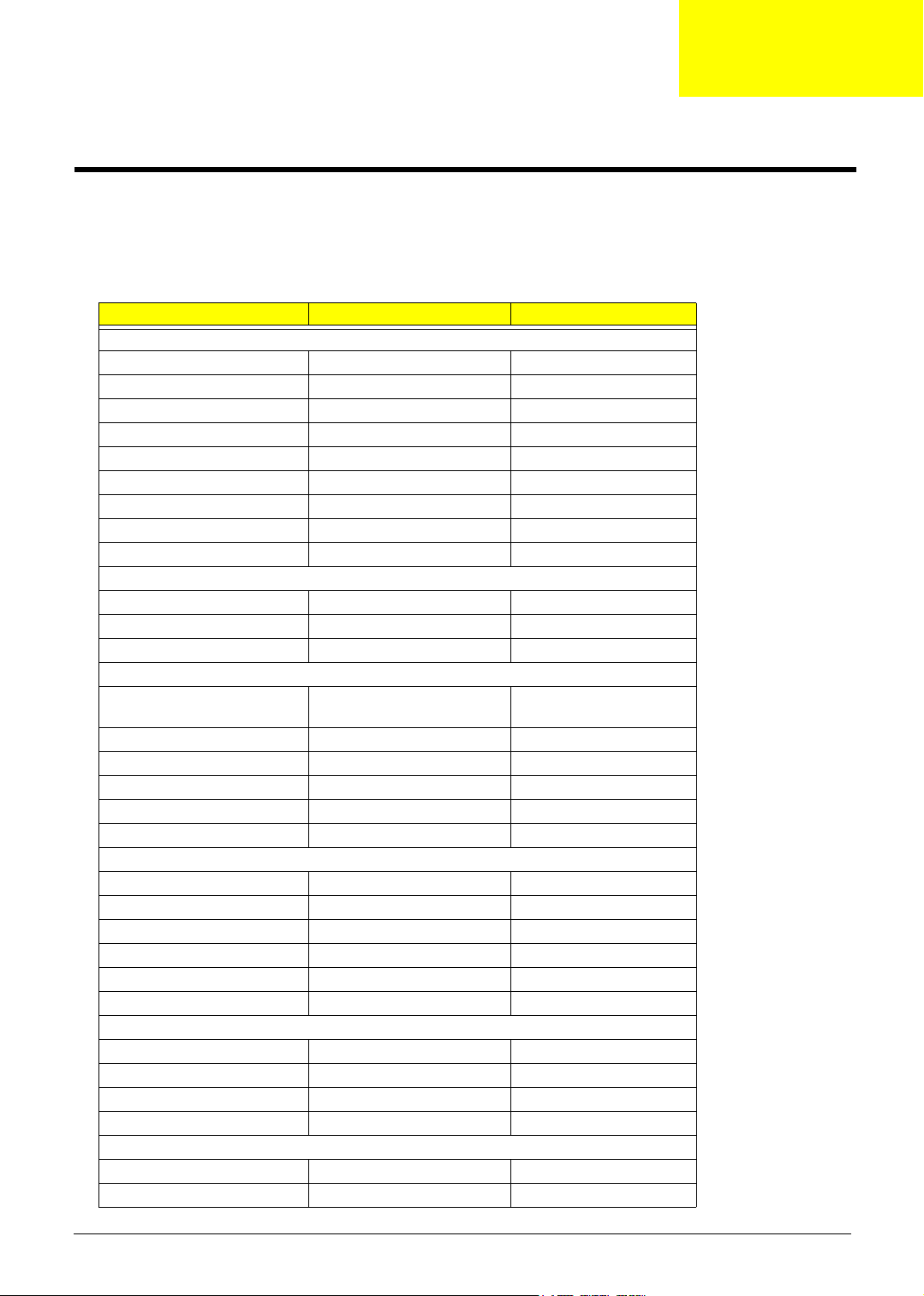
This chapter describes the product specification for the LCD TV AT3705
Model AT3705-MGW AT3705-DTV
Panel spec
Panel manufacturer CMO CMO
Panel model name V370H1-L01 V370H1-L01
Technology Super MVA Super MVA
Resolution 1920x1080 1920x1080
Brightness (typ.) 550 nits 550 nits
Contrast Ratio (typ.) 800:1 800:1
Display color 16.7 M 16.7 M
Viewing Angle (typ.) H:176 ; V:176 H:176 ; V:176
Response Time (typ.) 12 ms (Gray to Gray) 12 ms (Gray to Gray)
Power Supply
Input 100V~240V-AC. 100V~240V-AC.
Max.Power Consumption 280W 280W
Power Saving 5W 5W
Mechanical
Dimensions (WxHxD mm) 1018 (L) x 616 (H) x 210 (W) mm1018 (L) x 616 (H) x 210 (W)
mm
Weight (Kg) 36.0 36.0
Weight (lb) 79.3 79.3
Gross Weight (Kg) 42 42
Gross Weight (lb) 92.6 92.6
Wall Mounting 400mm x 200mm 400mm x 200mm
Mechanical
Dimensions (WxHxDmm) 1185 x 724 x 285 1185 x 724 x 285
Weight (Kg) 36.0 kg 36.0 kg
Weight (lb) 79.3 lb 79.3 lb
Gross Weight (Kg) 42kg 42kg
Gross Weight (lb) 92.6 lb 92.6 lb
Wall Mounting 400mm x 200mm 400mm x 200mm
Analog TV system
TV Color system NTSC NTSC
Sound system M M
Stereo system BTSC/ A2 BTSC/ A2
Analog TV Tuner quantity 1 1
Digital TV system
Digital TV Standard DVB-T DVB-T
Sound system
Chapter 1
Chapter 1 1
Page 8
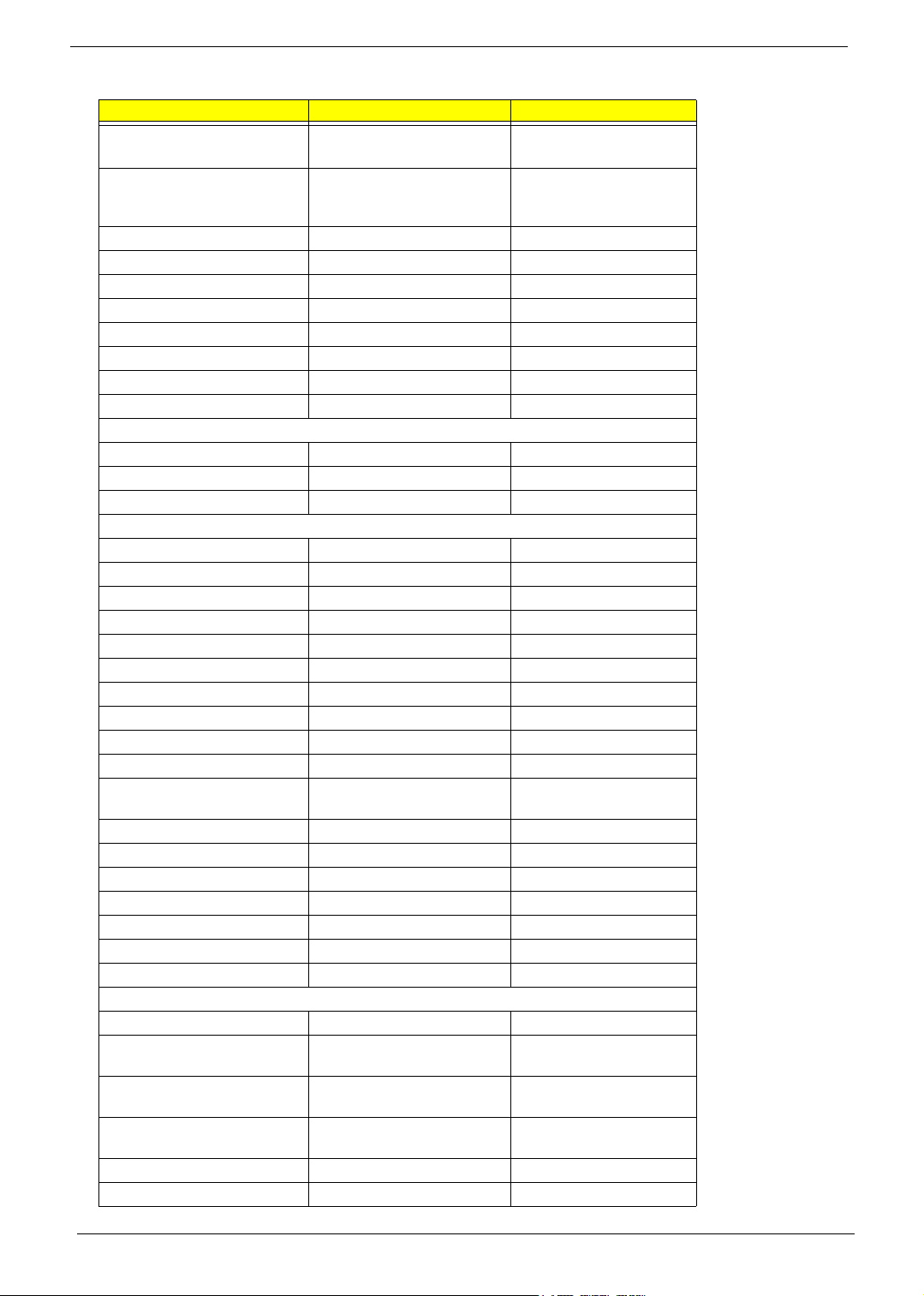
Model AT3705-MGW AT3705-DTV
ISO11172-3 layer1 & layer2
32KHz,44.1KHz,48KHz
Stereo system Dolby AC3 / PCM / MPEG (
Layer I & II ) Stereo 32 / 44.1 /
48KHz
SPDIF 2/4/6 Channel 2/4/6 Channel
Te le t ex t Ye s Yes
Subtitle Yes Yes
EPG 7days EPG 7days EPG
Frequency 6 MHz 6 MHz
Video format 16bit YUV 16bit YUV
Resolution SD(480i) SD(480i)
Digital TV Tuner quantity 1 1
Audio system
Speaker 15W+15W 15W+15W
Audio Enhancement "BBE, SRS WOW" "BBE, SRS WOW"
Digital Audio Dolby Digital Dolby Digital
Ter min al
Analog Tuner In Yes Yes
Digital Tuner In Yes Yes
Component1(HD) in "YPbPr/YCbCr,Audio R/L" "YPbPr/YCbCr,Audio R/L"
Component2(HD) in "YPbPr/YCbCr,Audio R/L" "YPbPr/YCbCr,Audio R/L"
Component3(HD) in "YPbPr/YCbCr,Audio R/L" "YPbPr/YCbCr,Audio R/L"
AV1 in "CVBS, S Video, Audio R/L" "CVBS, S Video, Audio R/L"
AV2 in "CVBS, S Video, Audio R/L" "CVBS, S Video, Audio R/L"
AV3 in "CVBS, S Video, Audio R/L" "CVBS, S Video, Audio R/L"
AV4 in "CVBS, S Video, Audio R/L" "CVBS, S Video, Audio R/L"
AV5 in "CVBS, Audio R/L" "CVBS, Audio R/L"
AV out "Analogy TV-CVBS out, Audio
R/L"
SPDIF out Yes Yes
DVI-D in yes (with HDCP) yes (with HDCP)
HDMI in yes (with HDCP) yes (with HDCP)
PC D-sub in Yes Yes
PC Audio in Yes Yes
Headphone out Yes Yes
RJ45 in Yes NA
Media Gateway
Card Reader "CF, MMC, MS, MS PRO, SD," NA
Audio "LPCM, MP3, WMA7/8/9,
WAV"
Video "MPEG1/2/4, DivX, XViD,
WMV9, Quicktime (*.mp4);"
Video(HD) "MPEG2 (up to 1080i), MPEG4
(720p), WMV9 (720p)"
Photo "JPEG, TIFF, BMP, GIF, PNG" NA
Playlist "M3U, PLS" NA
ISO11172-3 layer1 & layer2
32KHz,44.1KHz,48KHz
Dolby AC3 / PCM / MPEG (
Layer I & II ) Stereo 32 / 44.1
/ 48KHz
"Analogy TV-CVBS out,
Audio R/L"
NA
NA
NA
2 Chapter 1
Page 9

Model AT3705-MGW AT3705-DTV
On-line media Live365 NA
Compliance "UPnP compliant, INMPR
compliant, DLNA"
Operating system Linux NA
Networking (WLAN) 802.11b/g: 11/54Mbps NA
Networking (Fast Ethernet) 10/100Mbps NA
NA
Chapter 1 3
Page 10

Abbreviations / symbols
The main abbreviations used in this document are listed below with their meanings:
CCIR International Radio consultative committee
CVBS Composite Video Baseband Signal
dBm dB milliWatt
dBµV dB microVolt
DAR Display Aspect Ratio
DV Digital Video
DVI Digital Video Interface
ESD Electro Static Discharges
FP Front panel keypad
IC Integrated Circuit
IF Intermediate Frequency
IR Infra Red
KP Keypad
MN Menu
MTBF Mean Time Between Failure
OIRT International Radio and Television Organization
OSD On Screen Display
PLL Phase Locked Loop
PIP Picture-in-Picture
PAP Picture And Picture
RC Remote Control
RF Radio Frequency
RGB Video Components : Red / Green / Blue
SCART 21 pins SCART plug
SWR Standing Wave Ratio
TBD To Be Defined
TV Television Set
VBI Vertical Blanking Interval
VCR Video Cassette Recorder
Page 11

VESA Video Electronics Standard Association
VGA Video Graphics Array
VHF/ UHF Very High Frequency / Ultra High Frequency
Y/C S-Video signals : Luminance / Chrominance
YprPb Video Components : Luminance / R-Y / B-Y
FB Fast Blanking
SB Slow Blanking
USB Universal Serial Bus
HDMI High-definition multimedia interface
HDCP High bandwidth digital content protection
Page 12

ELECTRO / OPTICAL
1) Size of screen 37 inches
2) LCD Panel supplier CMO, AUO
3) Screen aspect ratio 16:9
4) Type of screen TFT with Super MVA technology or SIPS or QSV.
5) Screen resolution 1920 x 1080
6) Display colors 16.7 M colors ( 8 real bits per color )
7) Chromaticity Red 0.646 0.332
Green 0.269 0.600
Blue 0.142 0.072
White 0.285 0.293
(data from CMO panel specification)
8) Color temperature:
Five modes are adjustable,
Cold 16,000 degree K
Middle-cold 14,000 degree K
Standard 12,000 degree K
Middle-warm 10,000 degree K
Warm 8,000 degree K
9) White uniformity ± 5% of the white average color temperature at 100% luminance
10) White dispersion ± 5% of the white color temperature desired at 100% luminance
11) Brightness 500 Cd/m
2
(typical)
12) Contrast 450 :1 (typical)
13) Uniformity ≥ 85 % (white and color uniformity measured on 9 points)
Page 13

14) Overscan video source is with overscan supported
graphic source is without overscan supported
15) Vision angle ultra wide viewing angle: 176(H),176(V) (CR>20)
16) Gamma the gamma value (global value ) must be between 2.2 and 2.6 measured from
DVI
17) Response time (T
/ TF) ≤ 16ms (data is provided from CMO panel specification)
R
18) Screen (lamp + LCD) life > 50,000 hrs at nominal backlight intensity
19) CCFL backlight 20
20) Panel interface 2-ch LVDS
Page 14

MAINS
1) Power Supply Electrical Specifications
The power supply for this product is an internal converter, with a
non-replaceable fuse internally. This converter is designed to meet CE mark
requirement.
Input Voltage and Frequency Range
The operating range of line voltage is:
AC 90volts to 264volts, 47HZ to 63HZ
Power comsuption is under 280Watts
Line Fuse
The AC input is fused and becomes electrically open as a result of an
unsafe current condition. This fuse is inside the power supply converter
and is not user replaceable, and must be returned for replacement.
This fuse is well selected to handle inrush current for all combinations of
line voltage and frequency.
2) Standby consumption < 5 W
3) Power consumption < 280 W
4) Mains disturbance behavior no disjunction during 0 to 40ms mains interrupt, with
max load, min mains voltage
No software reboot during the test.
No over voltage causing any damage during mains interrupt (0 to
any time )
5) Inverter The inverter which is used to light up back-light of LCD panel is well designed to
meet requirement of panel’s specification.
Page 15

ACOUSTICAL / AUDIO
1) Audio power amplifier 2 x 12W rms on 8ohm load impedance.
2) Loudspeakers Attachable ,( 1 x full range + 1 x sub-woofer speakers ) x 2
3) Loudspeaker performances Max. Audio output ( at 10% THD max. ) at 1.0Vp-p / 1kHZ input : 15W +15W
Sound Distortion at 1W/1kHZ : 1% THD max.
Speaker : Two of 15W
Speaker impedance : 8 ohms at 1kHZ
Residual Hum at Min. Volume : 500uW Max.
Max. Hum at Max. Volume : 1000uW Max.
4) Analog TV Audio modes AM/FM mono, stereo, sound1, sound2.
5) Audio Enhancement Stereo
SRS WOW
BBE
* audio enhancements effect is audible at 5M in front of the screen
6) Acoustical noise ( completeTV) audible noise in standby mode < 35dBA (ISO-7779)
audible noise in power ON mode < 35dBA (ISO-7779)
parasitic noise due to mechanical vibration during audio sweep
must be inaudible at 1m around the TV .
Page 16
HARD / SOFT PERFORMANCES
1) Supported Languages Czech, Danish, Dutch, English, French, German, Italian, Polish, Portuguese,
Russian, Spanish, Swedish
2) Starting time A correct picture (color, aspect ratio, stability) can be displayed
< 6 sec after Power ON
3) Wake-up behavior The system can be waken up if the button Standby is pressed (keypad ‘power’ or
remote control ‘power’, ‘0~9’, ‘CH+/-‘)
4) Stand-by reason The TV pass in standby mode upon :
• The button ‘power’ is pressed (keypad or remote control)
• On the selected source: no sync signal after 8 mins.
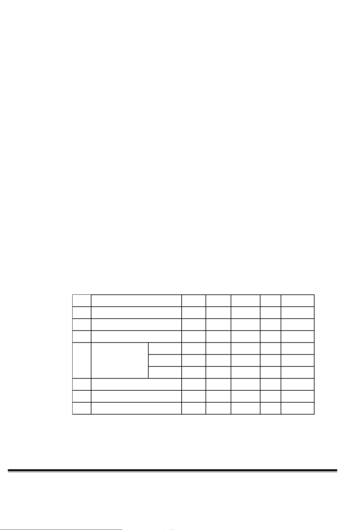
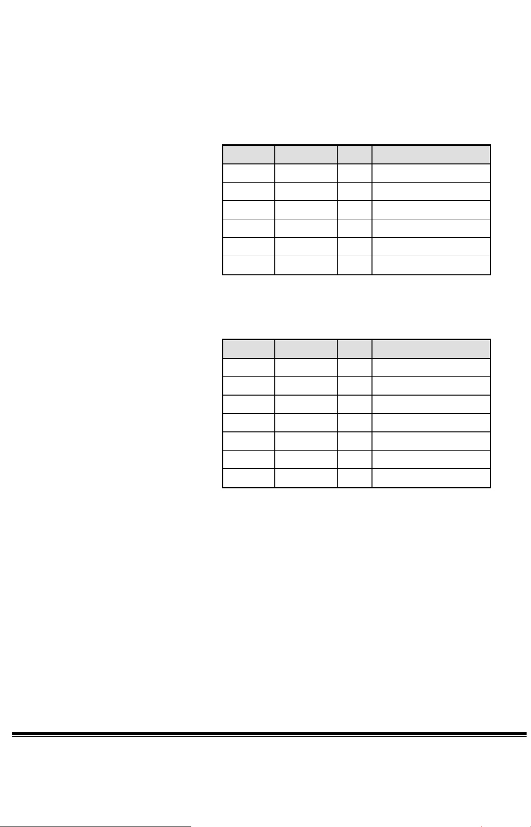
5) Analog tuner performances
No. PARAMETER MIN TYP MAX UNIT NOTE
1 Video output level 0.7 1.0 1.3 Vp-p
2 Video S/N 40 45 --- dB
3 Noise limiting --- 38 45 dbuV
4
Video frequency
characteristics
2Mhz 0.0 -1.5 dB
3Mhz -0.5 -2.5 dB
3.58Mhz -1.0 -4.0 dB
5 Audio output level 0.350 0.450 0.550 Vrms
6 Audio S/N 50 63 --- dB
7 Frequency Range 48.25 863.25 MHZ
Note : data is provided from tuner specification
6) DVBT module management Ref to AD6 module specification
Page 17

7) Scanning mode Automatic: Multistandard, frequency based
Manual : Frequency setting is available.
8) Analog TV Naming function Automatic : CNI recognition
Manual : 5 Characters
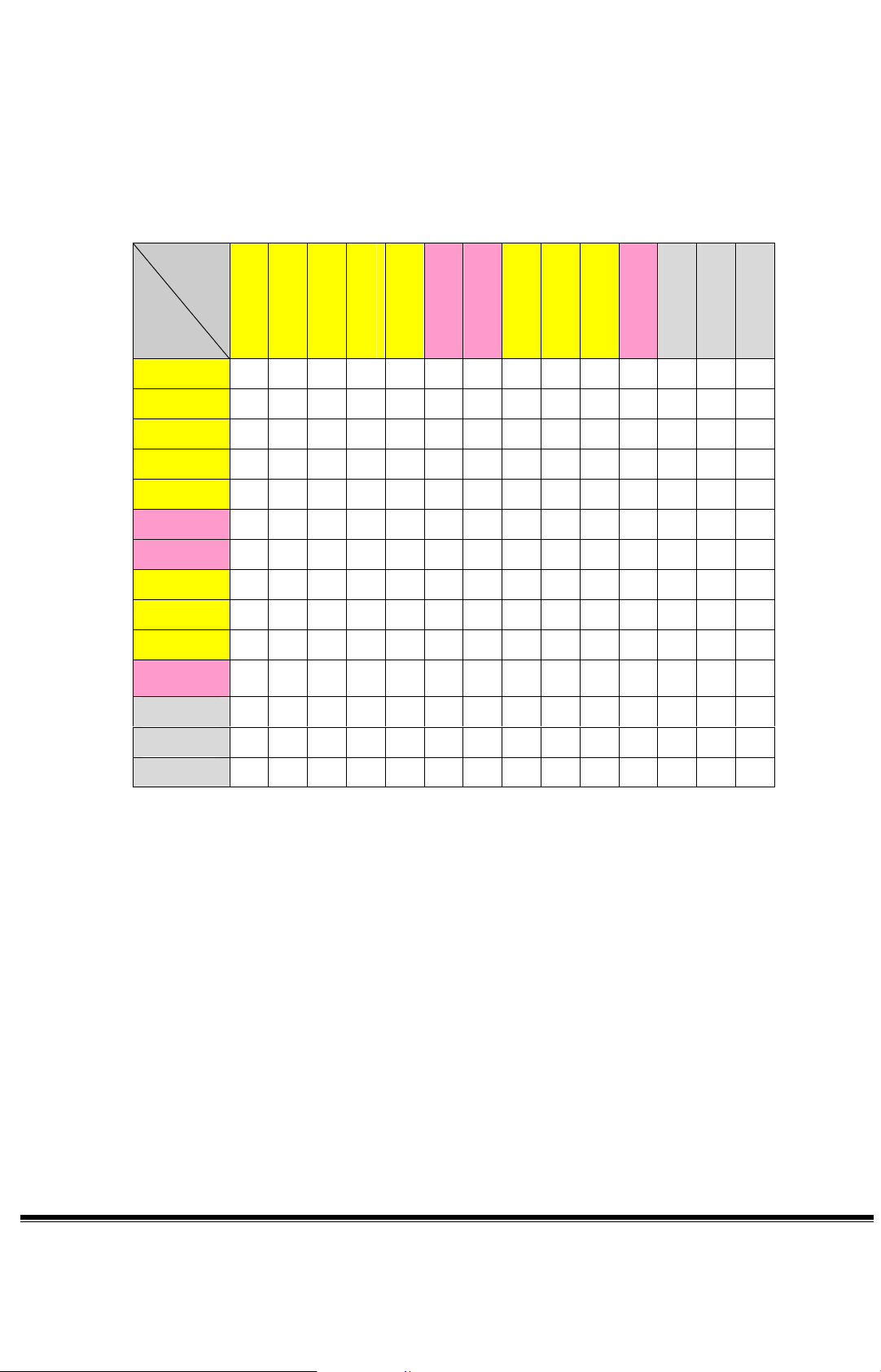
9) PIP/POP/PBP function PIP
PIP multiple size 20%, 30%
PIP multiple position 4 corners
POP
POP source video/graphic(main) by ATV(sub)
POP(main + sub) 1+5 , 1+12
In PIP/POP/PBP mode, de-interlacer does not support to 1080i.
PIP/PBP
1. Support Video by Video
2. Support Video by Graphic (support Graphic signal up to 1080i and No
deinterlacer in 1080i)
3. No Auto SCART is supported
4. VGA and DVI can only support up to 1024x768@60Hz
Note
z Video includes: ATV, SCART1-4 (CVBS and S-Video), AV1, AV2
and DTV.
z Graphic includes: component1, component2, MGW/CardReader,
VGA, DVI and HDMI.
Page 18
TV
SCART1
SCART2
SCART3
SCART4
Component 1
Component 2
AV1
AV2
DTV
MGW /Card
VGA
DVI
Main
Sub
HDMI
Q Q Q Q Q Q Q Q Q Q Q Q Q
TV
SCART1
SCART2
SCART3
SCART4
Component 1
Component 2
U
Q U
Q Q
Q Q
Q Q
U
U
Q Q Q Q Q Q Q Q Q Q Q Q
U Q Q Q Q Q Q Q Q Q Q Q
Q U Q Q Q Q Q Q Q Q Q Q
Q Q U Q Q Q Q Q Q Q Q Q
U U U U U U U U U U U U U
U U U U U U U U U U U U U
AV1
AV2
DTV
MGW/Card
VGA
DVI
HDMI
Q Q Q Q Q Q Q U
Q Q Q Q Q Q Q Q U
Q Q Q Q Q Q Q Q Q U
U U U U U U U U U U U U U
U
Q Q Q Q Q U
Q Q Q Q Q U
Q Q Q Q Q U
U Q Q Q U U U U
U Q Q Q U U U U
U Q Q Q U U U U
Q Q Q Q Q Q
Q Q Q Q Q
Q Q Q Q
(table of PIP & PBP)
Page 19
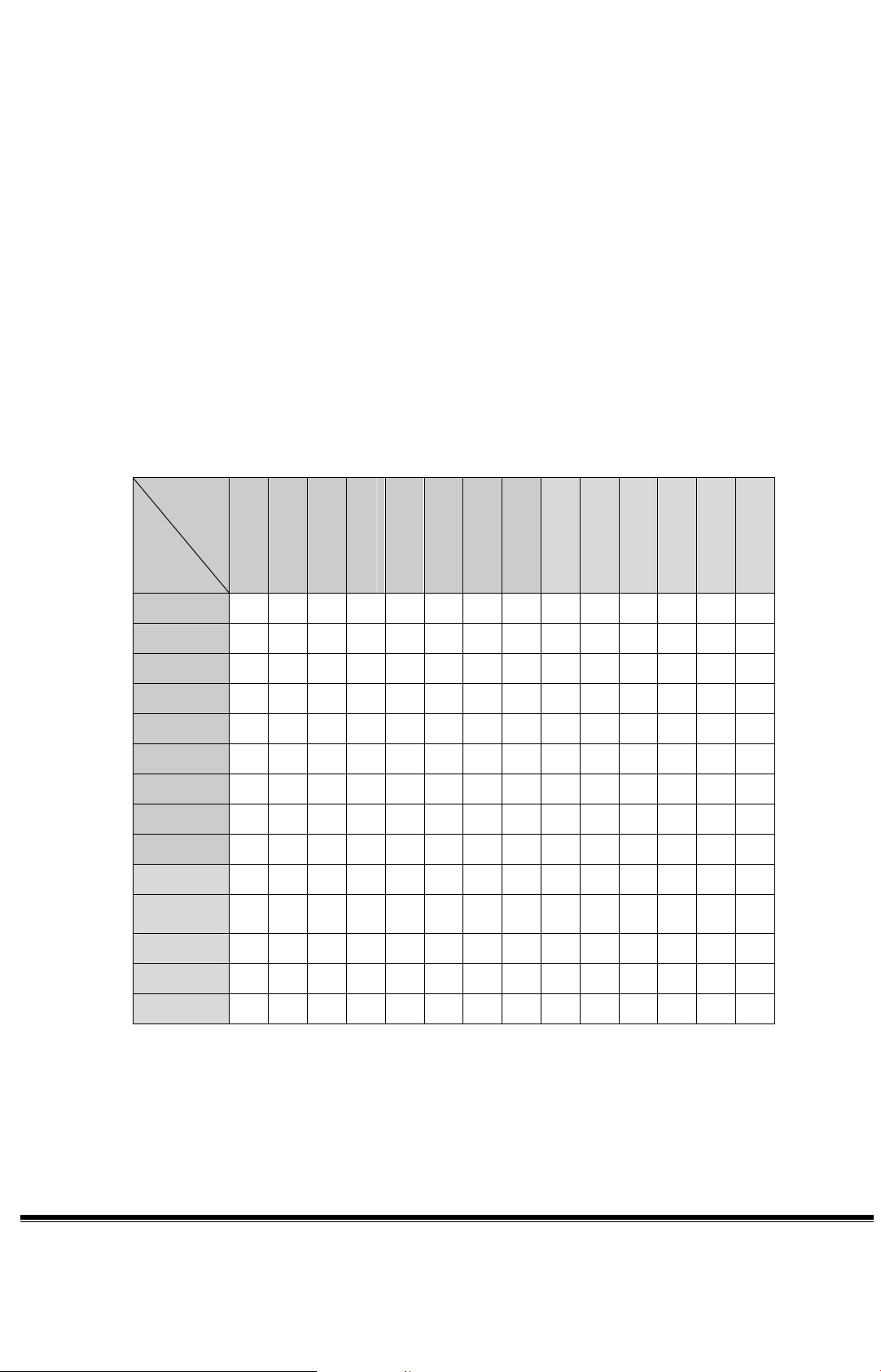
POP:
1. POP sub window only support Analog TV
2. No Auto SCART supported in POP mode
3. In POP12 Mode, support Component 1, 2 (up to 1080i) and MGW/Card
Reader (up to 1080i), VGA/DVI (up to 1024x768@60Hz) and HDMI (up
to 1080i)
4. In POP5 Mode, No MGW/Card Reader, VGA, DVI and HDMI supported
5. Component 1, 2 can support up to 720P in POP5 mode
1
.
2
.
TV
SCART1
SCART2
SCART3
SCART4
Component 1
Component 2
AV1
AV2
DTV
MGW/Card
VGA
DVI
Main
Sub
HDMI
TV
SCART1
SCART2
SCART3
SCART4
1
U Q Q Q Q
U U U U U U U U U U U U U U
U U U U U U U U U U U U U U
U U U U U U U U U U U U U U
U U U U U U U U U U U U U U
Q1Q
Q Q Q
2
Q
Q2 Q2 Q
2
Component 1
Component 2
AV1
AV2
DTV
MGW/Card
VGA
DVI
HDMI
U U U U U U U U U U U U U U
U U U U U U U U U U U U U U
U U U U U U U U U U U U U U
U U U U U U U U U U U U U U
U U
U U U U U U U U U U U U U U
U U U U U U U U U U U U U U
U U U U U U U U U U U U
U U U U U U U U U U U U U U
U U U U U U U U U U U U U U
(table of POP)
Page 20

10) TTX Level FLOF level 1.5. Source can be RF, DVBT or AV.
TTX characters set must follow the country language selection.
11) TTX keys function Full screen, Subtitle, Hold, Size, 4 Color keys (R, G, Y, B)
12) Video standard supported PAL, SECAM (automatic detection)
PAL (4.43 M, 50 Hz) B、G、D、K、H、I
SECAM L
13) Video ADC and processing 10 bits (chroma and luma)
Luma / chroma AGC,
10 bits processing,
Noise reduction,
Chroma transcient improvement,
Luma transcient improvement,
3D Comb filter,
De-interlacer.
14) Time to synchronize during a source / channel change, within 4 sec to obtain a stable
Display
15) Video management User adjustments: Contrast, Brightness, Color, Tint (NTSC),
Sharpness
Color Temperature: cold, middle-cold, Standard, middle-warm, warm
16) Aspect ratio Aspect ratio available for all the video sources.
4/3, 16/9, panorama, letterbox1, letterbox2, letterbox3.
Note: PC & DVI only support 4/3 & 16/9
17) Scenario functions Settings: Standard, movie, sport, concert, game, user
Noise reduction: Off, Low, Middle, High
Page 21
18) Audio management User adjustments: Volume, Balance, Bass, Treble,
MUTE, MONO/STEREO/Sound1/Sound2
19) Audio enhancement Stereo, SRS WOW, BBE
20) AV sub-format supported CVBS, YC, RGB, YUV
21) Copy protection management HDCP (HDMI)
22) MGW module Ref to Alpha MGW’s specification
23) Card reader function Ref to Alpha MGW’s specification
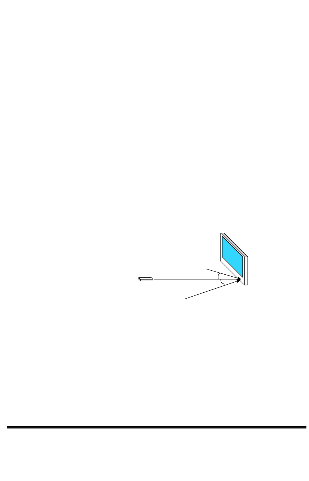
24) IR performances The reception distance indicate the distance between IR emitter
and receptor which allow to recognize 85% or more IR frames.
Reception distance : > 7.5 M perpendicular to the IR sensor
> 5 M at 45° horizontally
> 5 M at 45° vertically
7.5M in front of the IR sensor
X axis ± 45 ° at 5m
Y axis ± 45 ° at 5m
Page 22

INPUTS / OUTPUTS
1) RF 75 ohms input , according to CE regulation.
2) AV (SCART INPUT) 2 RGB SCART
Input signals: RGB CVBS, Left Right
Those inputs can be use in RGB mode or CVBS mode.
2 S-video SCART
Input signals: RGB CVBS, Left Right
Those inputs can be use in CVBS mode or YC mode.
3) AV (SCART OUTPUT) Output signals: TV CVBS out, Left Right
4) AV LEVEL Compatibility VIDEO
Type : CVBS/Analog
Polarity : Positive
Level : 1Vp-p ( with Sync.)
Impedance : 75Ω± 5%
Interface : 1) RCA jack, Yellow color
2) Euro_SCART, Black
Type : YC/analog
Level : Y : 1Vp-p ( with Sync.) C : 0.286Vp-p
Impedance : 75Ω± 5%
Interface : 1) mini-DIN jack, black color
2) Euro_SCART, Black
Type : RGB/analog
Polarity: Positive
Level: 0.7 Vp-p
Impedance: 75Ω ± 5 %
Interface: Euro-SCART
Page 23

Type : YUV/analog
Polarity : Positive
Level : Y : 1Vp-p ( with Sync.) U/V : 0.286Vp-p
Impedance : 75Ω± 5%
Interface : RCA jack,
Y : Green color
U : Blue color
V : Red color
Type : TV CVBS output/analog
output Level : 2Vp-p ( with Sync.)
Interface : 1) RCA jack, Yellow color
2) Euro_SCART, Black
AUDIO
Type: PC line in (Stereo R/L Channels)
Level: 500 mVrms
Impedance: More than 22Kohm
Interface: 3.5mm Stereo jack, bluish color
Type : Stereo R/L Channels
Level : 500mVrms
Impedance : More than 22kΩ
Jack : RCA jack ,
SPDIF output level : 400mVrms
Jack : RCA Jack (Orange)
5) AV (YC CVBS) one input
Input signals: CVBS, Left Right or YC Left Right
Right : Red color.
Left : White color
6) COMPONENTS one input
Input signals: YPbPr LEFT RIGHT or
Page 24
YCbCr LEFT RIGHT
Format Resolution Type Vertical frequency
7) HDMI one input
480i 720 x 480 SD 59.940Hz, 60Hz
480p 720 x 480 SD 50Hz, 59.940Hz, 60Hz
576i 720 x 576 SD 50Hz
576p 720 x 576 SD 50Hz
720p 1280 x 720 HD 50Hz, 59.940Hz, 60Hz
1080i 1920 x 1080 HD 50Hz, 59.940Hz, 60Hz
Format Resolution Type Vertical frequency
VGA 640 x 480 59.94Hz, 60Hz
800 x 600 60Hz, 72Hz, 75Hz
XGA 1024 x 768 60Hz, 75Hz.
480p 720 x 480 SD 50Hz, 59.940Hz, 60Hz
576p 720 x 576 SD 50Hz
720p 1280 x 720 HD 50Hz, 59.940Hz, 60Hz
1080i 1920 x 1080 HD 50Hz, 59.940Hz, 60Hz
8) DVI-D one input
Input signal DVI-D , Left Right (shared with VGA input)
Page 25
NO Timing V-Freq(Hz)
1 720X400 (DOS) 70 Hz
2 640X480 (DOS) 60 Hz
3 72 Hz
4 75 Hz
5
640X480(VESA)
85 Hz
6 56 Hz
7 60 Hz
8 72 Hz
800X600(VESA)
9 75 Hz
10
85 Hz
11 60 Hz
12 70 Hz
1024X768(VESA)
13 75 HZ
14
85 Hz
15 1152 X864(VESA) 75 Hz
16 1280 X960(VESA) 60 Hz
17 1280 X1024(VESA) 60 Hz
18 1920 X 1080 (HD) Interlace, 60Hz
9) VGA one input
Input signal VGA , Left Right
NO Timing V-Freq(Hz)
1 640X350 85Hz
2 640X400 85Hz
3 720X400 85Hz
4 60Hz
5 72Hz
640X480
6 75Hz
7
8 56Hz
800X600
9
85Hz
60Hz
Page 26

10 72Hz
11 75Hz
12 85Hz
13 60Hz
14 70Hz
1024X768
15 75Hz
16
85Hz
17 1152X864 75Hz
18 60Hz
19
20 60Hz
21
1280X720
75Hz
1280X768
75Hz
22 1280X960 60Hz
23 1280X1024 60Hz
24 1366X768 60Hz
25 1400X1050 60Hz
26 1440X900 60Hz
27 1920 X 1080 (HD) Interlace, 60Hz
28 640X350 70Hz
29 720X400 70Hz
30 640X480 66.7Hz
31 832X624 75Hz
32 1024X768 75Hz
33 1152X870 75Hz
10) Sound management in GRAPHIC : in HDMI, the audio source is inside the HDMI signal
In VGA and DVI-D, the audio comes from the audio graphic connector.
11) EDID management: EDID data format version >= 1.3
EDID update from VGA plug, DVI, HDMI are available.
12) Card reader See Card reader Functions and Card reader connector: those
Page 27

function is included in the MGW module
13) Headphone The user can adjust separately the headphone volume.
The load impedance is 32 ohms, with 0.5W max output.
The audio signal can be any input source displayed in active window
14) HIFI On the HIFI outputs, the user can connect an external audio
amplifier, the selected signal is the same as the loudspeaker.
The output level is 500mV RMS
15) Loudspeakers Max. Audio input (at 10% THD max.) at 1.0Vp-p / 1kHZ input: 15W +15W
Sound Distortion at 1W/1kHZ : 1% THD max.
Speaker : Two of 15W
Speaker impedance : 8 ohms at 1kHZ
Residual Hum at Min. Volume : 500uW Max.
Max. Hum at Max. Volume : 1000uW Max.
Page 28

CONNECTORS
1) Tuner type IEC 69-2 fem following: IEC 600169-2
2) AV Type SCART following: EN 50 049 –1
RCA following: IEC 933-5
Jack 3.5 mm
VGA connector fem following: VESA
DVI-D connector
HDMI type A following: EIA/CEA 861B
3) Card reader type Compact Flash Type I / II
Smart Media
Secure Digital card
XD card
Memory Stick
Memory Stick pro
Multi MediaCard
4) Color SCART black
Jack black
Mini Din black
Audio Left white
Audio Right red
CVBS yellow
Y Green
P
P
/ CB blue
B
/ CR red
R
Page 29

T
5) Accessibility Front :
Side:
Function Video connector Audio connector
Audio Right / Left
AV2 CVBS input (RCA)
(2 x RCA)
Audio Right / Left
Headphone output -
Jack fem 3,5mm
Card reader
Rear :
Function Video connector Audio connector
RF analog input IEC69-2 fem
RF digital input IEC69-2 fem
SCART1 RGB/CVBS SCART (EN 50 049 –1)
SCART2 YC/CVBS SCART (EN 50 049 –1)
SCART3 RBG/CVBS SCART (EN 50 049 –1)
SCART4 YC/CVBS SCART (EN 50 049 –1)
Component1
Component2
AV1
HDMI HDMI
DVI-D DVI-D
VGA SUB-D15
AV output
Compact flash or
7 in 1 adapter
Y, U, V
(3 x RCA)
Y, U, V
(3 x RCA)
YC (1 x mini-DIN)
CVBS (1 x RCA)
V CVBS out
(1 x RCA)
-
Audio Right / Left
(2 x RCA)
Audio Right / Left
(2 x RCA)
Audio Right / Left
(2 x RCA)
Audio Right / Left
(Jack fem 3,5mm)
Audio Right / Left
(2 x RCA)
SPDIP out (1 x RCA)
Page 30

USER INTERFACE
1) Menu type see UI specification for detail
2) Remote control see UI spec
3) Response time typical 300ms
4) Keypad (7 keys) ON/OFF , MENU , INPUT,
VOL+, VOL -
CH + , CH –
5) IR codes see UI specification for detail
6) LED indication In standby mode Amber
In normal operation Blue
7) Pin code The pin code allows to lock the complete TV or execute channel lock.
A menu is displayed after the POWER UP of the TV.
For operation of this function, please refer to UI specification
8) Sleep Function It’s time to power off TV off/15/30/45/60/90/120 mins selectable
9) Remote control NEC protocol
TV custom code refer to UI spec
DVBT custom code refer to UI spec
MGW custom code refer to UI spec
Page 31

SERVICE
1) Software upgrade Mainboard software and DVB-T software update available by after sales service
Services term shall follow Service Contract defined with customers
Page 32

ACCESSORIES
Following accessories would be contained to shipout with LCD TV.
Cables
Power Cord
Lan cable is provided with MGW model only
Remote Controller
Remote controller
AAA battery
Others
User Manual
Warranty Card
Quick guide
MGW installation kit, provided with MGW model only
Page 33

MECHANISM SPECIFICATION
Cosmetic and quality standards for injection molded plastic parts
This specification defines the criteria to be used for inspection resulting in the acceptance or rejection of
parts due to visual, cosmetic and functional requirements for customer visible surfaces.
Surface quality
Surface color, gloss, texture, blemishes, and all other irregularities in the plastic shall comply with QCI’s
approval sheet.
Fade and color change
All external surfaces shall be sufficiently rugged to withstand normal operator usage without extreme
visible deterioration in color. The delta E must not exceed the value of 0.5 after 400 hours of UV
testing.
Reflectivity of surface ( Reserved )
Appearance Gap Specifications
Please refer to Cosmetic specification.
Torque Specifications
Common criterion
Torque ( Kg-cm )
Item Screw Type
W/Plastics W/Plastics W/Plastics
1 M2 x L 2~3 kg 2~3 kg M: Machine thread
2 T2 x L 2~4 kg 4~6 kg 2~4 kg T: Tapping thread
3 M2.5 x L 5~7 kg 3~5 kg
4 T2.5/2.6 x L 3~5 kg 3~5 kg 2~3 kg
5 M3 x L 4~6 kg 3~5 kg
6 T3 x L 4~6 kg 6~8 kg 4~6 kg
7 M4 x L 8~10 kg
8 T4 x L 7~9 kg
Remark
Page 34

Physical Specifications
Overall Dimensions:
Height : 725 mm
Width : 1185 mm
Depth : 285 mm
Base
Tilt: 0°
Swivel: 0°
Mass
Mass of display with cable approx.: 42 Kg
VESA Mounting Holes
According to Vesa FPMPMI standard.
4 holes 300 mm x 100 mm (4mm, 0.7 pitch threaded) in the rear center for ARM.
Logo and Rating Label
It’s customized
Packing Specifications
It’s customized
Page 35

ENVIRONMENTAL REQUIREMENTS
The TV shall meet the following environmental requirements under normal operating conditions.
Operating
25° ± 5° for Purity, White Point, Mis-convergence, Luminance measurements and White uniformity
measurement
Operating temperature 0°C to 40°C
Operating humidity 10% to 90% (non-condensing)
Storage and Shipping
Storage temperature -10°C to 60°C
Shipping temperature -10°C to 60°C
Storage humidity 10% to 90% (non-condensing)
Altitude
Shipping humidity 10% to 90% (non-condensing)
Operating altitude 0 to 12,000 feet
Units tested at an altitude up to 12,000 feet must operate at normal conditions without exhibiting
abnormal behavior such as arcing or shutdown.
Shipping altitude 0 to 40,000 feet
Storage altitude 0 to 40,000 feet
Page 36

REGULATORY REQUIREMENTS
Product Safety
This display unit complies with following safety standards.
TUV compliance: EN60950 safety specification-business equipment
Emissions/Susceptibility
This display unit complies with the following EMC regulations.
CE Mark compliance:
EN60950
EN 55022 ( CISPR 22, Class B )
IEC 1000-4-2 ESD: EN55024-2 or EN61000-2
IEC 1000-4-3 RS ( Radiated ): EN55024-3 or EN61000-3
IEC 1000-4-4 EFT: EN55024-4 or EN61000-4
IEC 1000-4-5 Surge: EN55024-5 or EN61000-5
IEC 1000-4-6 RS ( Conducted ): EN55024-6 or EN61000-6
IEC 1000-4-8 Power Frequency Magnetic Field Immunity
IEC 1000-4-11 Voltage Dips, Short Interruptions, and Short Variations Immunity
Page 37

RELIABILITY PERFORMANCE
Electrostatic Discharge Requirements
This display shall withstand 8kV for contact discharge and 15kV for air discharge of Electrostatic
Discharge to meet the acceptance criteria as specified in IEC 1000-4-2.
Mean time between failure (MTBF)
For the purposes of demonstrating the MTBF of this product, a failure is defined as the inability of
the product to function in accordance with this specification. A failure event interrupts the expected
operation of the product and requires service or repair to restore the product to full functionality.
The MTBF of this product is target meet or exceed 20,000 hours @ 25 °C at a 90% confidence limit
under all operating conditions as specified in previous section.
Page 38

Machine Disassembly and Replacement
This chapter contains step-by-step procedures on how to disassemble the LCD TV for maintenance and
troubleshooting.
To disassemble the TV, you need the following tools:
T Wrist grounding strap and conductive mat for preventing electrostatic discharge
T Small Philips screw driver
T Philips screwdriver
T Plastic flat head screw driver
T Tweezers
NOTE: The screws for the different components vary in size. During the disassembly process, group the
screws with the corresponding components to avoid mismatch when putting back the components.
When you remove the stripe cover, please be careful not to scrape the cover.
Chapter 3
Chapter 3 32
Page 39

General Information
Before You Begin
Before proceeding with the disassembly procedure, make sure that you do the following:
1. Turn off the power to the system and all peripherals.
2. Unplug the AC adapter and all power and signal cables from the system.
3. Remove the battery pack.
NOTE: There are several types of screws used to secure the product. The screws vary in length. Please refer
the picture below, group the same type of screws together during service disassembling. Please also
remember the screw location for each screw type. If you fasten the screw to the wrong location, the
screw may be too long to damage the main board.
33 Chapter 3
Page 40

Disassembly Procedure
Removing the Speaker
1. Press the latch to release speaker cable.
2. Remove the four screw securing the right speaker.
3. Remove the right speaker.
4. Repeat the same steps for left speaker.
5. Remove the four screws securing the right speaker bracket and remove it from speaker.
6. Repeat the same steps for left speaker.
Chapter 3 34
Page 41

Removing the TV Stand Module
1. Remove the four screws securing the TV stand module.
2. Remove the TV stand module.
Remving the I/O
1. Remove the six screws securing the I/O cover.
2. Remove the I/O cover.
3. Remove the 20 screws securing the I/O bracket.
4. Remove the I/O bracket.
Removing the Down Cover
1. Remove the five screws securing the down cover
35 Chapter 3
Page 42

2. Remove the four nuts securing the down cover.
3. Push the down cover a little bit backward.
4. Remove the down cover as shown.
5. Remove the 20 screws securing the back cover.
6. Lift the back cover up.
7. Disconnect the left speaker connector from back cover.
Chapter 3 36
Page 43

8. Remove the two screws securing the left speaker board.
9. DIsconnect the right speaker connector from the back cover.
10. Remove the two screws securing the right speaker board.
11. Remove the back cover as shown.
Removing the Top Shielding
1. Remove the screws securing the top shielding.
2. Push the top shielding a little bit upward.
37 Chapter 3
Page 44

3. Remove the top shielding.
Removing the DMA board
1. Disconnect the following connectors and antennas.
DMA-M/B
Antenna
DMA-LANboard
DMA-CardReader
2. Remove the six screws securing the DMA board and remove it.
Removing the Power Board
1. Disconnect the connectors from power board.
power boardDtuner, I/O board,
M/B
power board
-aueio board
power boardinverter board
Chapter 3 38
Page 45

2. Remove the 9 screws securing the power board and remove the power board.
Removing the Converter Board
1. Disconnect the connectors from converter board.
converter-LCD board
converter-M/B
2. Remove the four screws securing the converter board.
3. Remove the converter board.
Removing the Audio Board
1. Disconnect the cables from audio board.
power board-audio
board
audio boardI/O board
audio board-speaker board
2. Remove the four screws securing the audio board.
39 Chapter 3
audio board-AV3
Page 46

3. Remove the audio board.
Removing the I/O board and A-tuner Board
1. Disconnect the connectors from I/O board.
I/O board-AV3
power board
-I/O board
2. Remove the four screws securing the I/O board and four screws securing the A-tuner board.
3. Remove the I/O board and A-tuner board.
4. Separate the I/O board and A-tuner board.
I/O board
-audio board
Chapter 3 40
Page 47

Removing the Heatsink
1. Remove the four screws securing the heatsink.
2. Remove the heatsink from the main unit.
Removing the Ethernet Board
1. Remove the two screws securing the ethernet board.
2. Remove the ethernet board.
3. Disconnect the cable from the ethernet board.
41 Chapter 3
Page 48

4. Remove the two screws securing the ethernet bracket and remove the bracket.
Removing the D-tuner
1. Remove the three screws securing the D-tuner.
2. Remove the D-tuner.
Removing the M/B and D-tuner Board
1. Disconnect the cables from Mainboard and D-tuner board.
M/B-LVDS
M/B-inverter
board
M/B-power
button board
M/B-DMA board
D-tuner board-power
board
M/B-power
board
Chapter 3 42
Page 49

2. Remove the four nuts and two screws securing the mainbaord.
3. Remove the two screw, three short nuts, and four long nuts securing the D-tuner board.
short nuts
4. Remove the M/B and D-tuner board.
5. Separate the M/B and D-tuner board.
four long nuts
Removing the Card Reader module
1. Remove three screws securing the card reader module.
43 Chapter 3
Page 50

2. Remove two screws securing the ground wire.
3. Turn the card reader module over and disconnect the cables from card reader module.
4. Disconnect the cables from AV3 board.
I/O-AV3
audio-AV3
5. Remove the two screw securing the AV3 board and remove it from card reader module.
Chapter 3 44
Page 51

Removing the Bezel Skirt
1. Remove the 6 screws securing the bezel skirt.
2. Remove the bezel skirt.
Removing the IR Board, Power Button Board, and Keypad Board
1.
2. Remove the two screws securing the keypad board and remove it.
Chapter 3 45
Page 52

3. Remove the two screws securing the IR board, and remove the two screws securing the power button
board.
Removing the PCB Chassis
1. Disconnect the cables from LVDS board.
2. Remove the 7 screws on chassis bottom view.
3. Remove the 10 screws on chassis top view.
46 Chapter 3
Page 53
4. Remove the PCD chassis as shown.
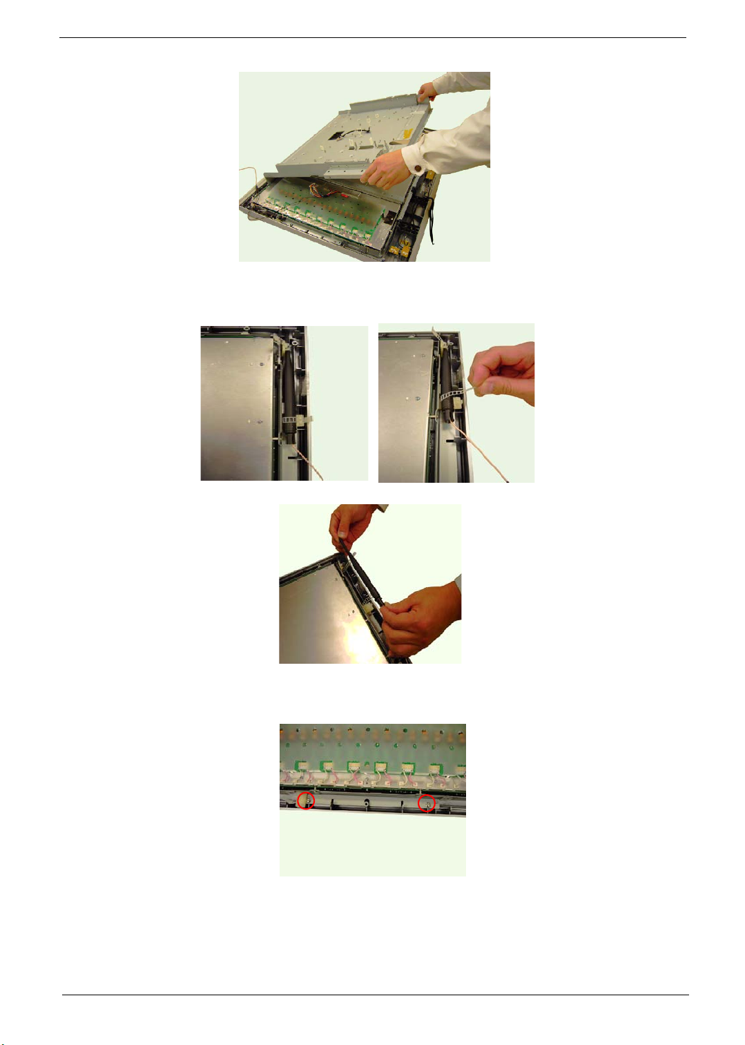
Removing the Antenna
1. Open the clip to release the antenna.
2. Remove the antenna.
Removing the LCD Panel
1. Remove the two screws on the right.
Chapter 3 47
Page 54

2. Remove the two screws on the left.
3. Remove the LCD panel.
4. Remove the two screws securing the right side bracket.
5. Remove the four screws securing the down bracket.
down bracket
6. Remove the right side bracket.
side bracket
48 Chapter 3
Page 55

7. Remove the down bracket.
8. Repeat the same steps for left side and top bracket.
Chapter 3 49
Page 56

50 Chapter 3
Page 57

Chapter 6
FRU (Field Replaceable Unit) List
This chapter gives you the FRU (Field Replaceable Unit) listing in global configurations of LCD TV AT3705W.
Refer to this chapter whenever ordering for parts to repair or for RMA (Return Merchandise Authorization).
Please note that WHEN ORDERING FRU PARTS, you should check the most up-to-date information available
on your regional web or channel. For whatever reasons a part number change is made, it will not be noted on
the printed Service Guide. For ACER AUTHORIZED SERVICE PROVIDERS, your Acer office may have a
DIFFERENT part number code from those given in the FRU list of this printed Service Guide. You MUST use
the local FRU list provided by your regional Acer office to order FRU parts for repair and service of customer
machines.
NOTE: To scrap or to return the defective parts, you should follow the local government ordinance or
regulations on how to dispose it properly, or follow the rules set by your regional Acer office on how to
return it.
Chapter 6 94
Page 58

Exploded Diagram
86
87
97
88
89
8:
96
93
98
92
62
61
63
64
65
66
67
68
69
6:
71
72
73
74
75
76
91
77
78
79
7:
81
82
83
84
85
51
4:
49
48
47
46
45
44
43
42
8:
41
59
58
57
56
55
54
53
52
5:
94
3:
39
38
37
36
35
34
33
32
31
2:
29
28
27
26
25
24
23
22
21
:
9
8
7
6
5
4
3
2
Number Item Number Item
1
AV3 door assy 2 Label
3 Bezel-sub assy 4 Speaker sponge-R
5 IR board assy 6 Power-key assy
7 LED board assy 8 Screw T3*8-B(BNI)
9 Function Key 10 Keypad board assy
11 Screw M3*6-B(BNI) 12 Earphone board assy
13 AV3 bracket 14 Card Reader Module
15 AV3 SHD-A 16 Cable assy card reader
17 Cable assy USB 18 Condctive Tape
19 Bezel skirt 20 Screw T4*16-B(BNI)
21 Panel bracket down 22 Speaker cap
23 LCD panel 24 Panel bracket side
25 Antenna 26 Speaker assy
95 Chapter 6
Page 59

Number Item Number Item
27 Speaker bracket 28 Cable assy MB-key/IR/
29 Gasket panel/holder 30 PCB-holder assy
31 power 300W 32 Screw M4*6 P(NI)
33 Cable assy inverter-MB/
power
35 Cable assy power-audio 36 Wire mount
37 Cable assy power 38 Thermal module_N assy
39 Rubber 40 Stand assy
41 Screw M6*15-B(BNI) 42 Cable assy speaker-R
43 Back cover assy 44 Speaker board
45 IO nut 46 Label(IO&Tuner)
47 ESD down media
gateway
49 IO bracket 50 IO cover
51 Screw T3*8 P(Black) 52 ESD top
53 Heatsink
55 Cable assy HH6 GND-
GND
57 Audio board assy 58 Clip standoff
59 Cable assy MB-DMA 60 AD6 tuner board(DVB-T)
61 Tuner board assy(A) 62 DMA module ADM-530E
63 Cable assy RJ45 64 Ethernet module
65 RJ11 bracket 66 D-Tuner nut L6.5
67 MB nut L17.5 68 IO board assy(PAL)
69 AD6 CPUBD(DVB-
T,PA N -E U ) a ss y
71 Gasket Panel 72 Cable assy LVDS
73 Panel bracket top 74 Clip MWS-2
75 Clip antenna 76 Cable assy ground
77 Cable assy ear-audio 78 Cable assy I/O-AV3
79 Speaker sponge-L 80 Spacer_TP-18
81 Cable assy speaker-L 82 Screw M3*12-B(BNI)
83 Screw M4*10-B(BNI) 84 Screw M3*4-B(NI)
85 Scew T4*12-B(NI) 86 Screw M4*6-B(NI)
87 Screw M3*6-B(BNI)
34 Cable assy LVDS/power
48 Label power
54
56 Cable assy I/O-audio
70 M/B assy
Power key
Gasket ESD T/D
assy
Chapter 6 96
Page 60
FRU List
Image PARTNAME DESCRIPTION PART NO.
ACCESSORY
N/A REMOTE CONTROL - EU DVBT+MGW LFREMOTE CONTROL 54-
N/A REMOTE CONTROL - USA
N/A REMOTE CONTROL - TAIWAN
N/A REMOTE CONTROL - AUSTRALIA
N/A REMOTE CONTROL - EU DTV LF REMOTE CONTROL 54-
N/A REMOTE CONTROL - USA DTV LF 25.M08V7.006
N/A REMOTE CONTROL - TAIWAN DTV LF 25.M08V7.007
N/A REMOTE CONTROL - AUSTRALIA DTV
BOARD
DVBT+MGW LF
DVBT+MGW LF
DVBT+MGW LF
LF
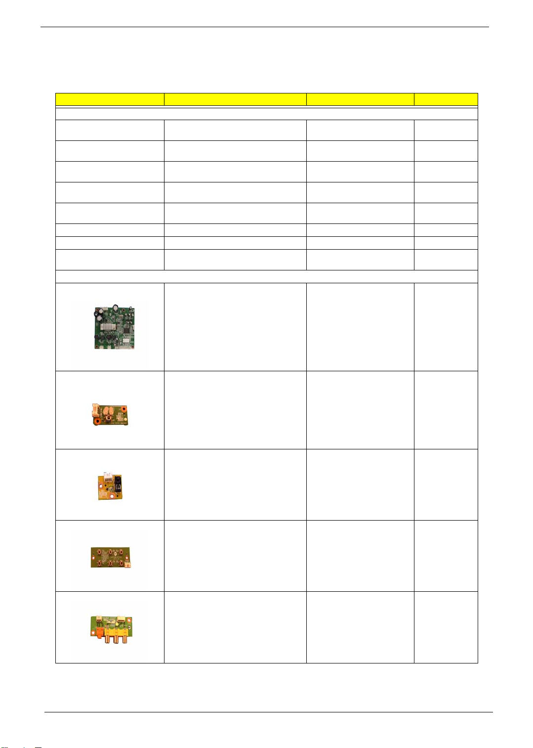
AUDIO BOARD VWE7 AUDIO/B ASSY 55.M08V7.001
33614 (EU)DVBT+MGW LF
36225 (EU)DVBT LF
25.M08V7.001
25.M08V7.002
25.M08V7.003
25.M08V7.004
25.M08V7.005
25.M08V7.008
LED BOARD VWE LED/B ASSY 55.M08V7.002
IR BOARD VWE IR/B ASSY 55.M08V7.003
KEYPAD BOARD VWE KAYPAD/B ASSY 55.M08V7.004
AV3/EARPHONE BOARD VWE7 EARPHONE/B ASSY 55.M08V7.005
97 Chapter 6
Page 61

Image PARTNAME DESCRIPTION PART NO.
SPEAKER BOARD VWE7 SPEAKER/B ASSY 55.M08V7.006
DVB-T BOARD - EU AUS TWN "AD6 CPUBD (DVB-T,PAN-
N/A CARD READER MODULE CARDREADER MODULE
"PWR 300W,DPS-300AP13A(90~264VAC)EU"
CONVERTER BOARD POWER SUPPLY 18V 18W
DMA BOARD W/WIRELESS CARD "DMA MODULE ADM-
EU) ASSY"
ADM-530R(5V)
"PWR 300W,DPS-300AP13A(90~264VAC)EU"
A94PS-028 LF
530M(12V,1A)"
55.M08V7.007
55.M08V7.008
55.M08V7.009
55.M08V7.010
55.M08V7.011
ETHERNET MODULE ADM530E(IEEE802.11G)
I/O BOARD - PAL VWE7 IO/B ASSY(PAL) 55.M08V7.013
A-TUNER BOARD - PAL VWE TUNER/B ASSY(A) 55.M08V7.014
ETHERNET MODULE ADM530E(IEEE802.11G)
55.M08V7.012
Chapter 6 98
Page 62

Image PARTNAME DESCRIPTION PART NO.
D-TUNER BOARD - DVB-T AD6 TUNERBD (DVB-T)
ASSY
55.M08V7.015
MAINBOARD DTV + MGW - PAL AUS VW2 M/B ASSY(FOR VWE)
N/A MAINBOARD DTV- PAL AUS VW2 M/B ASSY(FOR VWE7)
CABLE
N/A POWER CORD SP-023+IS-14H05VV-
F3P 1.8M EU
CABLE - IO BOARD TO AUDIO 11P/13P CABLE ASSY VWE7 IO-
CABLE - POWER BD TO AUDIO 8P/7P CABLE ASSY VWE7 PWR-
CABLE - AV3/EARPHONE TO AUDIO
4P/4P
BASE
BASE
POWER CORD SP-023+IS14H05VV-F3P 1.8M EU
AUDIO 11P/13P R2A EP
AUDIO 8P/7P R2A EP
CABLE ASSY VWE7 EARAUDIO 4P/4P R2A EP
55.M08V7.016
55.M08V7.017
27.M03V7.002
50.M08V7.001
50.M08V7.002
50.M08V7.003
N/A CABLE - GROUND 1P/1P CABLE ASSY VWE7
CABLE - INV(CMO37) TO MB/PWR R2A EPCABLE ASSY VWE7
CABLE - POWER CABLE EP CABLE ASSY VWE7 POWER
GROUND 1P/1P R3A EP
INV(CMO37)-MB/PWR R2A
EP
REV 2A EP
50.M08V7.004
50.M08V7.005
50.M08V7.006
99 Chapter 6
Page 63

Image PARTNAME DESCRIPTION PART NO.
CABLE - SPEAKER-L 3P/3P CABLE ASSY VWE7
SPEAKER-L 3P/3P R2A EP
50.M08V7.007
CABLE - SPEAKER-R 3P/2P CABLE ASSY VWE7
CABLE - IO BOARD TO AV3/
EARPHONE 6P/6P
CABLE - MB TO DMA 24P/24P CABLE ASSY VWE7 MB-
CABLE - MB TO KEYPAD/IR/PWKEY
EP
SPEAKER-R 3P/2P R2A EP
CABLE ASSY VWE7 IO-AV3
6P/6P R2A EP
DMA 24P/24P R2A EP
CABLE ASSY VWE7 MBKEY/IR/PWKEY R2A EP
50.M08V7.008
50.M08V7.009
50.M08V7.010
50.M08V7.011
CABLE - LCD (CMO37) TO
CONVERTER
CABLE - LVDS(CMO37) TO MB CABLE ASSY VWE7
CABLE ASSY VWE7
LVDS.PWR(CMO37) R2A EP
LVDS(CMO37) R2A EP
50.M08V7.012
50.M08V7.013
Chapter 6 100
Page 64

Image PARTNAME DESCRIPTION PART NO.
CABLE - CARD-READER 7P/7P CABLE ASSY VWE7 CARD-
READER 7P/7P R3A EP
50.M08V7.014
CABLE - USB 5P/5P R3A EP CABLE ASSY VWE7 USB 5P/
CABLE - DMA TO ETHERNET RJ45 5P/5PCABLE ASSY VWE7 RJ45
N/A CABLE - SCART-SCART VA1 20P/20P "CABLE ASSY SCART-
N/A CABLE - TC1 LAN 2M (RJ45/8P) CABLE ASSY TC1 LAN 2M
CASE/COVER/BRACKET ASSEMBLY
BACK COVER ASSY VWE7 BACK COVER ASSY 60.M08V7.001
5P R3A EP
5P/5P R3A EP
SCART VA1(20P/20P,R3A)"
(RJ45/8P)
50.M08V7.015
50.M08V7.016
50.M03V7.019
50.M08V7.017
PCB CHASSIS VWE7 PCB-HOLDER ASSY 33.M08V7.001
LCD PANEL BRACKET TOP "PANEL BKT TOP
LCD PANEL BRACKET SIDE "PANEL BKT SIDE
VWE7(FBVWE002,REV3A)"
VWE7(FBVWE003,REV3B)"
33.M08V7.002
33.M08V7.003
101 Chapter 6
Page 65

Image PARTNAME DESCRIPTION PART NO.
LCD PANEL BRACKET DOWN "PANEL BKT DOWN
VWE7(FBVWE001,REV3B)"
33.M08V7.004
"FRONT BEZEL W/O POWER/FUN. KEY
, DOOR"
FUNCTION/POWER KEY DOOR VWE7 AV3 DOOR ASSY 42.M08V7.001
N/A VWE7 POWER-KEY ASSY VWE7 POWER-KEY ASSY 47.M08V7.001
"FUNCTION KEY
VWE7(EBVWE003,REV3B)"
DOWN COVER "ESD DOWN-BASE
VWE7 BEZEL-SUB ASSY 60.M08V7.002
"FUNCTION KEY
VWE7(EBVWE003,REV3B)"
VWE7(FBVWE012,REV3C)"
47.M08V7.002
33.M08V7.005
IO BRACKET "IO BKT
IO COVER "IO COVER
TOP SHIELDING "ESD TOP
BEZEL SKIRT "BEZEL SKIRT
VWE7(FBVWE004,REV3B)"
VWE7(EBVWE004,REV3A)"
VWE7(FAVWE002,REV3B)"
VWE7(EAVWE004,REV3B)"
33.M08V7.006
42.M08V7.002
33.M08V7.007
42.M08V7.003
Chapter 6 102
Page 66

Image PARTNAME DESCRIPTION PART NO.
STAND BASE ASSY VWE7 STAND ASSY 60.M08V7.003
ETHERNET BOARD BRACKET "RJ11 BKT
SPEAKER BRACKET "SPEAKER BKT
N/A SPEAKER CAP "SPEAKER CAP
AUDIO BOARD HEAT SINK "HEAT SINK(AUDIO/B) VWE2
I/O SHIELDING W/THERMAL PAD VWE7 THERMAL
VWE7(FBVWE008,REV3A)"
VWE7(FAVWE004,REV3C)"
VWE7(EBVWE014,REV3A)"
(FBVWE025,REV3A)"
MODULE_N ASSY
33.M08V7.008
33.M08V7.009
42.M08V7.004
23.M08V7.002
33.M08V7.010
"AV3 BKT VWE7(FBVWE005,REV3B)" "AV3 BKT
"AV3 SHD-A VWE7(FBVWE006,REV3A)" "AV3 SHD-A
LCD
N/A "LCD(TFT)V370H1-L03
V01(37"",1920*1080) LF"
SPEAKER
VWE7(FBVWE005,REV3B)"
VWE7(FBVWE006,REV3A)"
"LCD(TFT)V370H1-L03
V01(37"",1920*1080) LF"
33.M08V7.011
33.M08V7.012
56.M08V7.001
103 Chapter 6
Page 67

Image PARTNAME DESCRIPTION PART NO.
SPEAKER ASSY SPEAKER ASSY VWE7(FS-
COMMUNICATION MODULE
N/A ANTENNA 2.4GHZ- L (EFW1263A1)LF ANTENNA 2.4GHZ
N/A ANTENNA 2.4GHZ - R (EFW1266A1)LF ANTENNA 2.4GHZ
SCREW
SCREW "IO NUT VT1(MBVT1002,REV3A)" "IO NUT
SCREW "MB NUT L17.5
SCREW "D-TUNER NUT L6.5
SCREW SCREW M3*6-B(BNI) SCREW M3*6-B(BNI) 86.M08V7.003
SCREW SCREW M3.0*4.0-B(NI) SCREW M3.0*4.0-B(NI) 86.M08V7.004
SCREW SCREW M4*10-B (BNI) SCREW M4*10-B (BNI) 86.M03V7.002
SCREW SCREW M4*6 P (NI) SCREW M4*6 P (NI) 86.M01V7.002
SCREW SCREW M4.0*6.0-B(NI) SCREW M4.0*6.0-B(NI) 86.M08V7.005
SCREW SCREW M6*15-B(BNI) SCREW M6*15-B(BNI) 86.M08V7.006
SCREW SCREW T3*8-P(BLACK) SCREW T3*8-P(BLACK) 86.M03V7.003
SCREW SCREW T3*8-B(BNI) SCREW T3*8-B(BNI) 86.M08V7.007
SCREW SCREW T4*12 B (NI) SCREW T4*12 B (NI) 86.M01V7.008
SCREW SCREW T4*16-B(BNI) SCREW T4*16-B(BNI) 86.M08V7.008
SCREW SCREW M3*12-B(BNI) SCREW M3*12-B(BNI) 86.M08V7.009
MISCELLANEOUS
MISCELLANEOUS "SPEAKER SPONGE-R
MISCELLANEOUS "SPEAKER SPONGE-L
MISCELLANEOUS "GASKET PANEL
MISCELLANEOUS "CLIP ANTENNA
MISCELLANEOUS "CLIP MWS-2
MISCELLANEOUS "CLIP STANDOFF
MISCELLANEOUS "GASKET ESD T/D
MISCELLANEOUS "GASKET PANEL/HOLDER
MISCELLANEOUS "CONDUCTIVE TAPE
HD1(MBHD1001,REV3A)"
HD1(MBHD1002,REV3A)"
VWE7(GBVWE015,REV3A)"
VWE7(GBVWE016,REV3A)"
VWE7(GBVWE009,REV3C)"
VWE7(EBVWE019,REV3A)"
VWE7(EBVWE020,REV3A)"
VWE7(EBVWE011,REV3A)"
VWE7(GBVWE004,REV3B)"
VWE7(GBVWE011,REV3A)"
VWE7(JXVWE001,REV3A)"
WIRE MOUNT "WIRE MOUNT
0000023AA)LF
(EFW1263A1)LF
(EFW1266A1)LF
VT1(MBVT1002,REV3A)"
"MB NUT L17.5
HD1(MBHD1001,REV3A)"
"D-TUNER NUT L6.5
HD1(MBHD1002,REV3A)"
"SPEAKER SPONGE-R
VWE7(GBVWE015,REV3A)"
"SPEAKER SPONGE-L
VWE7(GBVWE016,REV3A)"
"GASKET PANEL
VWE7(GBVWE009,REV3C)"
"CLIP ANTENNA
VWE7(EBVWE019,REV3A)"
"CLIP MWS-2
VWE7(EBVWE020,REV3A)"
"CLIP STANDOFF
VWE7(EBVWE011,REV3A)"
"GASKET ESD T/D
VWE7(GBVWE004,REV3B)"
"GASKET PANEL/HOLDER
VWE7(GBVWE011,REV3A)"
"CONDUCTIVE TAPE
VWE7(JXVWE001,REV3A)"
VWE7(EBVWE010,REV3B)"
23.M08V7.001
50.M08V7.018
50.M08V7.019
86.M01V7.010
86.M08V7.001
86.M08V7.002
47.M08V7.003
47.M08V7.004
47.M08V7.005
47.M08V7.006
47.M08V7.007
47.M08V7.008
47.M08V7.009
47.M08V7.010
47.M08V7.011
47.M08V7.012
Chapter 6 104
Page 68
Image PARTNAME DESCRIPTION PART NO.
MISCELLANEOUS "VWX RUBBER(GAVWE001,REV3A)" "VWX
RUBBER(GAVWE001,REV3A
)"
47.M08V7.013
PACKING "CARTON COVER
PACKING "CARTON(BASE)VWE7(HFVWE002,RE
PAC KIN G " BOX
PACKING "EPS
PACKING "EPS
PACKING "ACER TAPE
PACKING "CARTON CLASP VW7(JXVW7001,3A)" "CARTON CLASP
VWE7(HFVWE011,REV3A)FLEX"
V3A)"
(MONITOR)VWE7(HEVWE001,REV3A)"
FOAM(UP)VWE7(HBVWE001,REV3B)"
FOAM(BASE)VWE7(HBVWE002,REV3B
)"
VV3A(JXVV3005,3A)7.2MM*500Y"
"CARTON COVER
VWE7(HFVWE011,REV3A)FL
EX"
"CARTON(BASE)VWE7(HFV
WE002,REV3A)"
"BOX
(MONITOR)VWE7(HEVWE00
1,REV3A)"
"EPS
FOAM(UP)VWE7(HBVWE001
,REV3B)"
"EPS
FOAM(BASE)VWE7(HBVWE
002,REV3B)"
"ACER TAPE
VV3A(JXVV3005,3A)7.2MM*5
00Y"
VW7(JXVW7001,3A)"
47.M08V7.014
47.M08V7.015
47.M08V7.016
47.M08V7.017
47.M08V7.018
47.M08V7.019
47.M08V7.020
105 Chapter 6
Page 69

Chapter 6 106
 Loading...