

Page 1

Features
LCD Panel
T Max. resolution: 1366x768
T 16 CCFTs Backlight system
T Display area: 32 inches(813.3mm) diagonal
T Display color: 16.7 M colors
T Input Signal: 1-ch LVDS
T Contrast ratio:500:1(Typical)
T Brightness: 500 Cd/m
T Response Time(Tr+Tf):16 ms
T Viewing angle: 85
IO functions
T RCA Jack for YPbpr, YCbCr, Video and Audio
T 4-pin S-Din for S-Video
T 15-pin D-Sub for VGA
T 24-pin DVI/HDCP for DVi-D
T F type terminal for TV/CATV input
T 3.5mm earphone jack for Audio Line input
T 3.5 mm earphone jack for Audio Line output
T 3.5 earphone jack for Earphone output
2
(Typical)
o
(L)/85o(R),85o(U)/85o(D)
Video Functions
T Support NTSC/PAL/SECAM video format
T SUpport 480i/576i, 480p/576p, 1080i and 720p format
T Build in CLosed Caption and V-Chip functions
T Build in motion adaptive 3D Digital Comb-filter
T Build in Dynamic adaptive smoothing filter
T Build in Dynamic temporal frame-filtering Noise Reduction
T Build in Dynamic motion and edge adaptive De-interlacing
T Film mode 3:2 &2:2 pull down
T Screen display model 16:9/4:3/PANORAMA/ZOOM/PIP/POP
Mechanical
T Swivel: 40
T VESA mounting holes
o
(R:20o,L:20o)
Multi-Sound System
T MTS(NTSC), FM-FM
1
Page 2

Power Source
T Input Voltage: 90~264V, 47~63Hz
T Input Current: 2.3A
T Power Consumption 210Watts
T Stand-by: 5 Watts Max.
Remote Controllers
T Multi-function remote controller
Speaker
T Internal Speaker: 10W x 2 stereo, volume adjustable
Others
T On screen display adjustment function
T ISP(In System Programming) function available for revising driver easily
2
Page 3
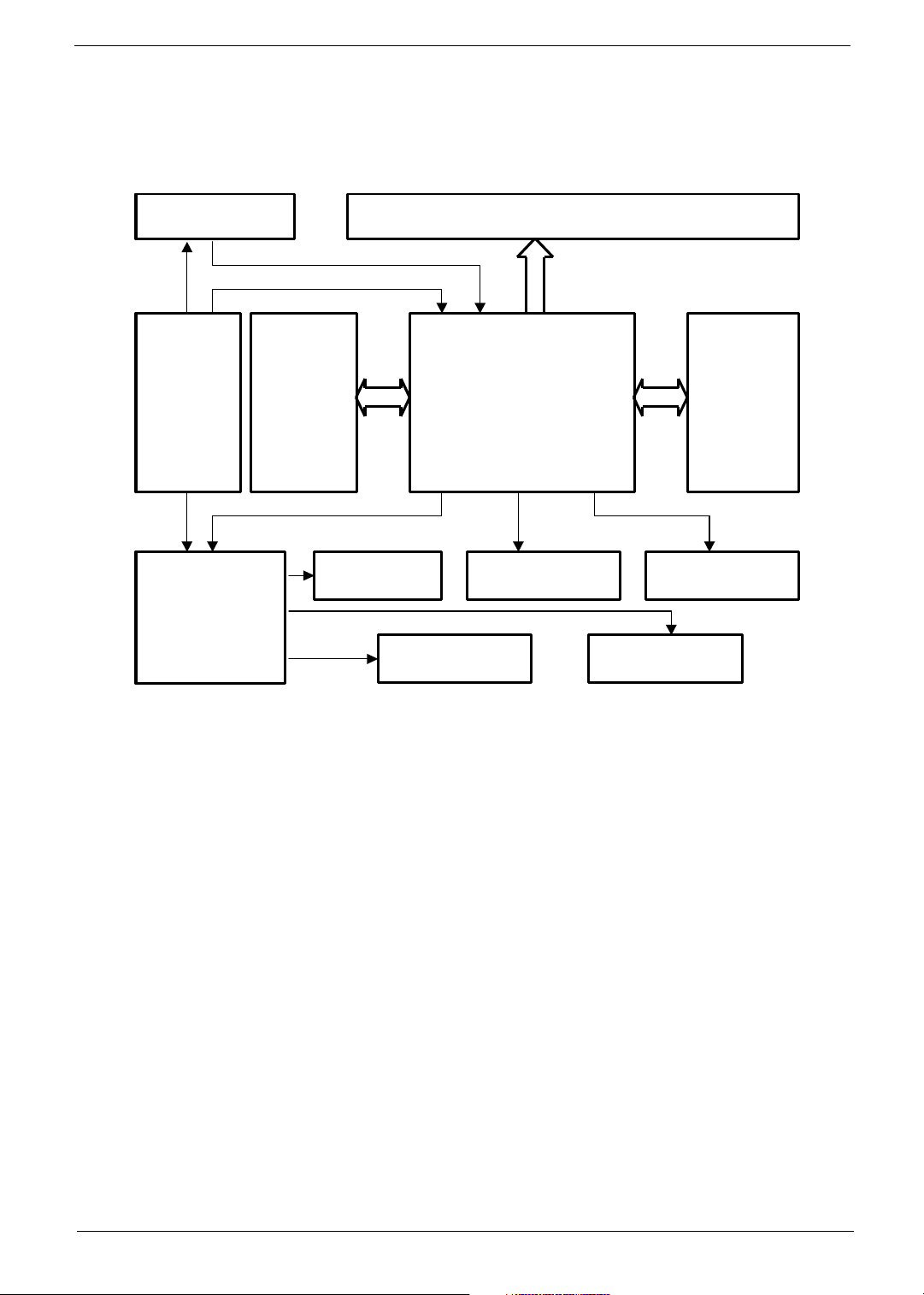
Block Diagram
AV 2
AV 1
d
A
AV 3
R
L
A
O
MAIN Board
P
System Block&Writing Diagram
INVERTE
POWER
Board
UDI
Board
Second
I/O Board
V 4
Earphone O/
PANE
IR Recever
SPEAKER-
I/O Board
Tuner
Key Boar
SPEAKER-
3
Page 4
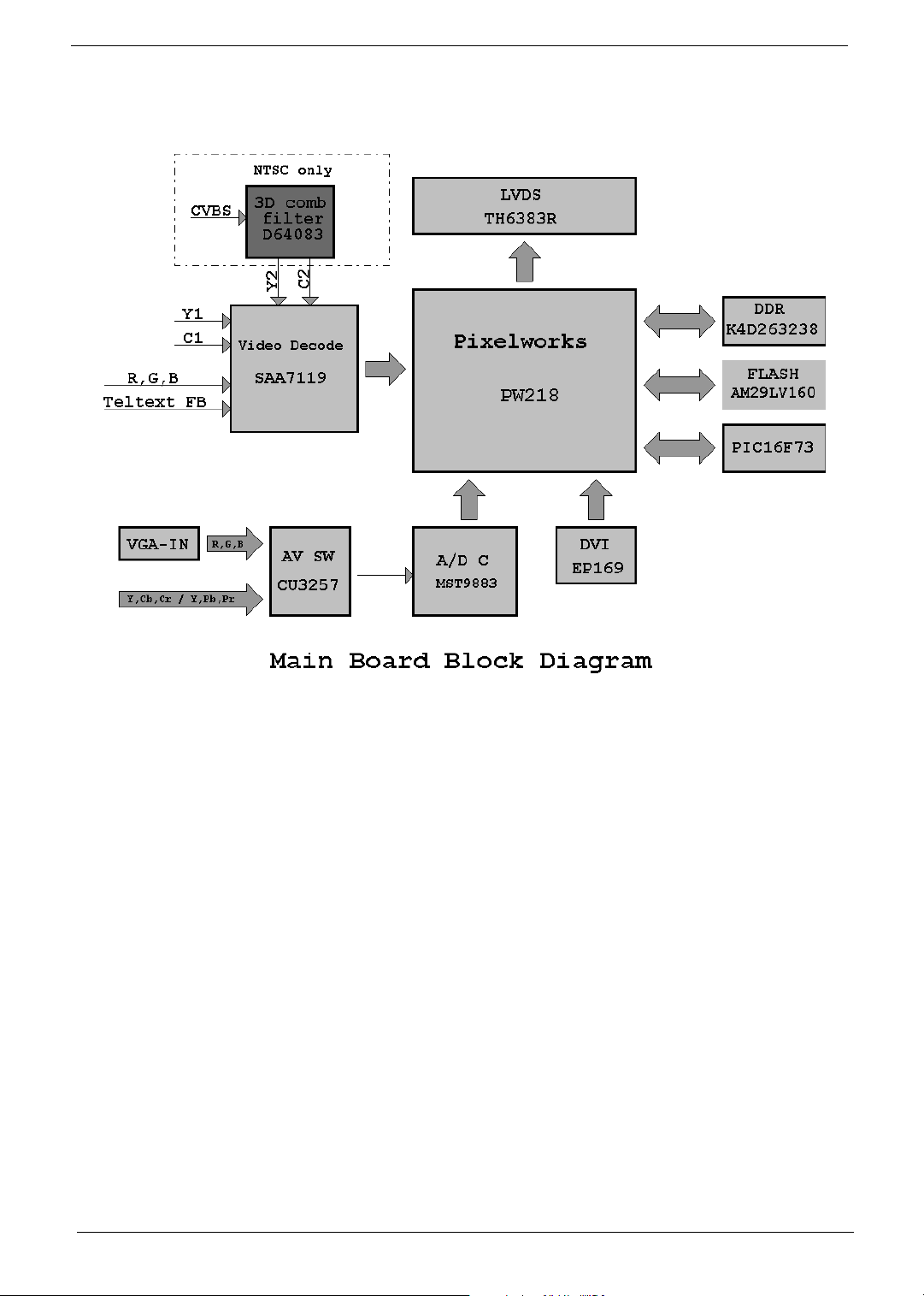
LCD Main Board Block Diagram
Components are subject to be
changed without prior notice.
4
Page 5
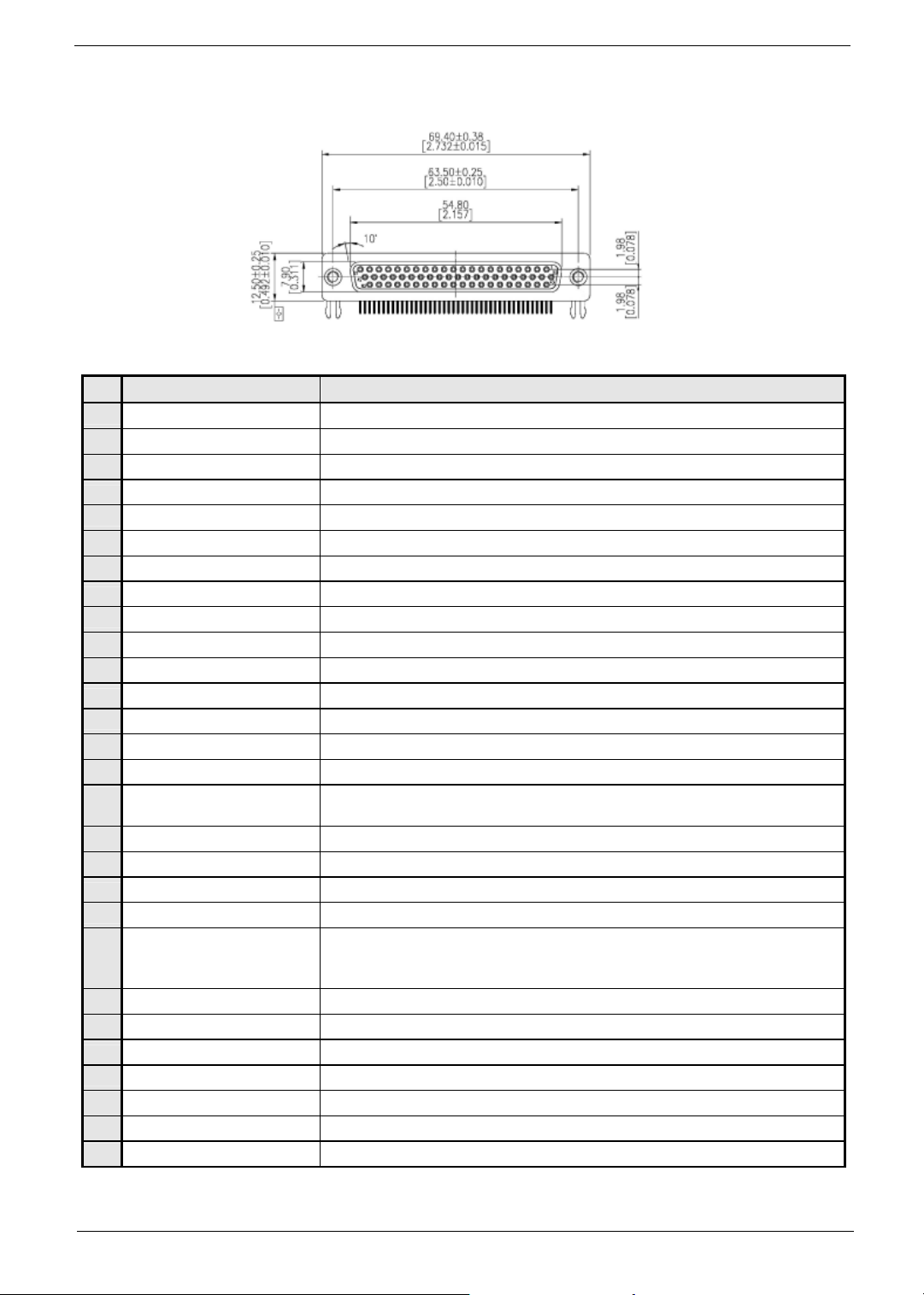
Pin Definition Between Main Board and I/O Board
s
No. Signal Name Function
1 Teletext_RGB_B ( 6 ) ‘ Blue ’ signal comes from Teletext decoder IC.
2 Teletext_RGB_G ( 6 )
3 Teletext_RGB_R ( 6 )
4 Teletext_fast_blanking
5 Teletext_start
6 SCART_aspect_ratio_1
7 DAC_RST ( 1 )
8 TX_232 ‘ TX ’ signal of UART
9 SVHS_2_C ( 3 ) ‘ Chrominance ’ signal of SVHS-2
10 SVHS_1_Return ( 3 ) Return path paired with Y and C of SVHS-1
11 SVHS_1_Y ( 3 ) ‘ Y ’ of SVHS signal set 1.
12 CVBS_1_Signal ( 2 ) CVBS-1
13 GND_1_of_( 3 ) Power ground
14 Audio_Center_Gnd_gnd ( 2 ) ‘ Ground ’ path paired with audio ‘ Center ’
15 Earphone_for_subpicture_L ( 2 ) Audio ‘ Left ’ channel paired with sub-picture.
16 Audio_Woofer_Gnd_woofer ( 2 )
17 Audio_Rear_L_R_Gnd_of_R ( 3 ) ‘ Right ’ signal of audio rear channels.
18 YUV_1_Pr ( 6 ) ‘ Pr ’ of YUV signal set 1.
19 YUV_1_Pb ( 6 ) ‘ Pb ’ of YUV signal set 1.
20 YUV_1_Y ( 6 ) ‘ Y ’ of YUV signal set 1.
21 Audio_Front_L_R_Gnd_of_R ( 3 )
22 Teletext_Vs ( 3, from main board )
23 Teletext_RGB_B_Return ( 6 )
24 Teletext_RGB_G_Return ( 6 )
25 Teletext_RGB_R_Return ( 6 )
26 GND_2_of_( 3 ) Power ground
27 SCART_mode_det_1 SCART mode detection ( RGB or CVBS )
28 RESET_I_O_Module LCDTV main board uses this pin to reset all components inside the I/O module.
‘ Green ’ signal comes from Teletext decoder IC.
‘ Red ’ signal comes from Teletext decoder IC.
Fast blanking signal for the use of Teletext decoder IC on I/O module.
Main board issues it for the use of Teletext decoder IC on the I/O module.
Aspect ratio indictor signal comes from pin-16 of ordinary SCART connector.
2
Main board used this pin to reset I
Audio woofer signal. After decoding Dolby digital or other surround audio, digital receiver sends thi
woofer signal to LCDTV main board for further processing.
‘ Right ’ channel of surround audio.
After decoding Dolby digital or other surround audio, digital receiver sends this signal to LCDTV main
board for further processing.
Vertical Sync. Signal issued by LCDTV main board for use of Teletext decoder IC on the I/O module.
‘ Blue ’ signal return for Teletext decoder IC.
Return path paired with ‘ Green ’ signal comes from Teletext decoder IC.
Return path of ‘ Red ’ signal comes from Teletext decoder IC.
C DAC on current I/O module.
5
Page 6
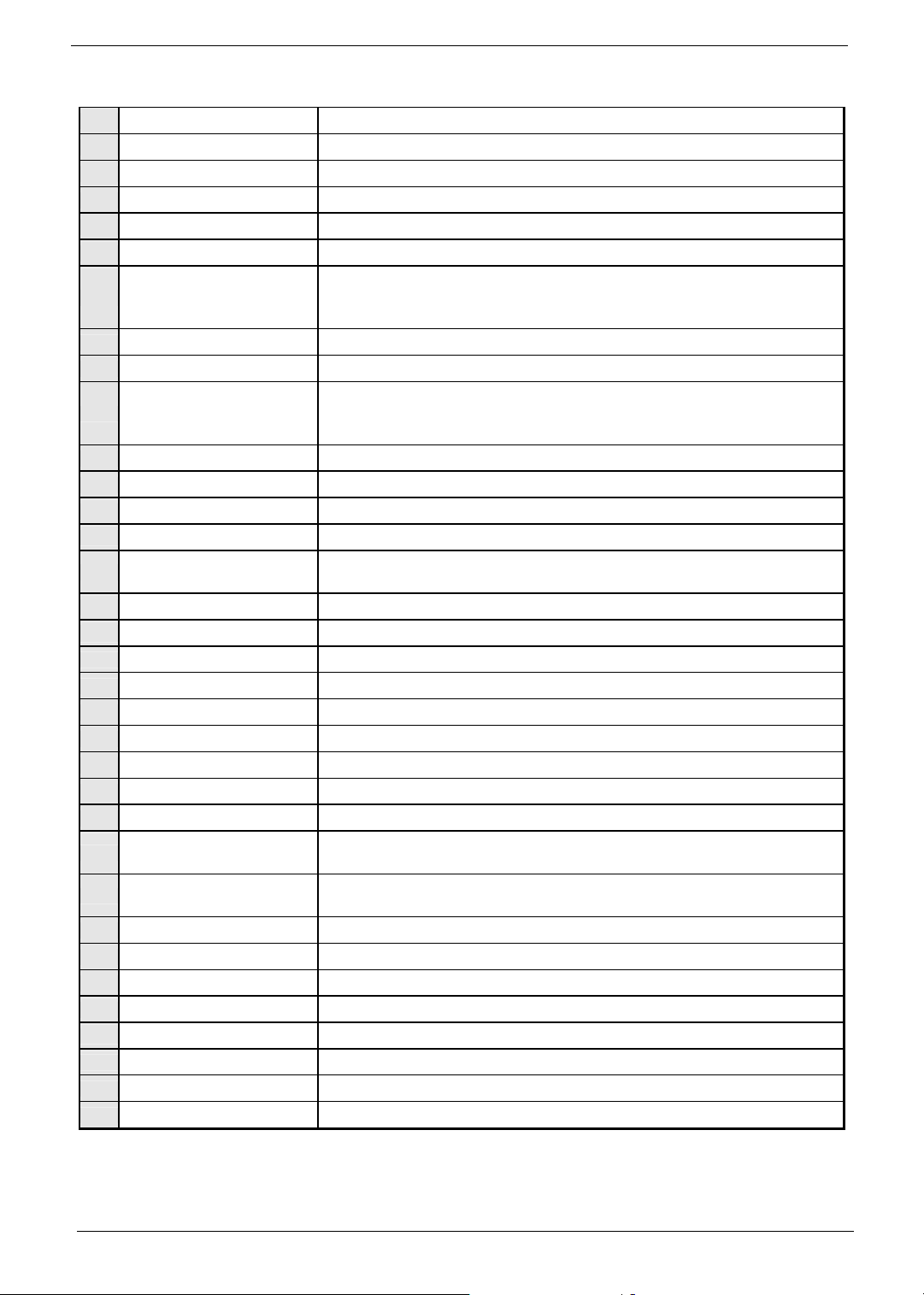
29 RX_232 ‘ RX ’ signal of UART
g
30 SVHS_2_Return ( 3 ) Return path paired with Y and C of SVHS-2
31 SVHS_2_Y ( 3 ) ‘ Y ’ of SVHS signal set 2.
32 SVHS_1_C ( 3 ) ‘ Chrominance ’ signal of SVHS-1.
33 CVBS_1_Return ( 2 ) Return path for CVBS-1
34 CVBS_2_Signal ( 1 ) CVBS-2
‘ Center ’ signal of surround audio channels.
35 Audio_Center_Gnd_signal ( 2 )
36 Earphone_for_subpicture_R ( 2 ) Audio ‘ Right ’ channel paired with sub-picture.
37 Audio_Woofer_Gnd_gnd ( 2 ) Ground signal paired with audio ‘ Woofer ’ channel.
38 Audio_Rear_L_R_Gnd_of_gnd ( 3 )
39 YUV_1_Pr_Return ( 6 )
40 YUV_1_Pb_Return ( 6 )
41 YUV_1_Y_Return ( 6 )
42 Audio_Front_L_R_Gnd_of_Gnd ( 3 ) ‘ Ground ’ path paired with audio front “ Left ” and “ Right ”
43 Teletext_Hs ( 3, from main board )
44
Teletext_Hs_Vs_return ( 3 ) Common return path of horizontal and vertical sync signals which are issued by LCDTV main board
45
TV_Out Video output for signal set AV3_OUT
46 TV_R Audio ‘ Right ’ channel of signal set AV3_OUT
47 TV_L Audio ‘ Left ’ channel of signal set AV3_OUT
48 Audio_Mute
49 12V_max_1A_a ( 2 )
50 12V_max_1A_b ( 2 )
51 5V_max_1.5A_a ( 2 )
52 5V_max_1.5A_b ( 2 )
53 USDA
54
USCL
55 ID_1 Identification signal -1
56 ID_2 Identification signal -2
57 GND_3_of_( 3 ) Power ground
58 Audio_Rear_L_R_Gnd_of_L ( 3 ) Audio ‘ Left ’ channel paired with sub-picture.
59 YUV_2_Pr ( 3 ) ‘ Pr ’ signal of YUV-2 signal set.
60 YUV_2_Pb ( 3 ) ‘ Pb ’ signal of YUV-2 signal set.
61 YUV_2_Y ( 3 ) ‘ Y ’ signal of YUV-2 signal set.
62 Audio_Front_L_R_Gnd_of_L ( 3 ) ‘ Left ’ signal of audio rear channels.
After decoding Dolby digital or other surround audio, digital receiver sends this signal to LCDTV main
board for further processing.
Ground signal of rear left and right audio channels.
After decoding Dolby digital or other surround audio, digital receiver sends this signal to LCDTV main
board for further processing.
Return path of ‘ Pr ’ signal. It belongs to YUV signal set –1.
Return path of ‘ Pb ’ signal. It belongs to YUV signal set –1.
Return path of ‘ Y ’ signal. It belongs to YUV signal set –1.
Horizontal Sync signal. LCDTV main board issues it for the use of Teletext decoder IC on the I/O
module.
Disable all the analog audio signals from I/O modules
Power pins which supply +12V to digital receiver.
Power pins which supply +12V to digital receiver.
Power pins which supply +5V to digital receiver.
Power pins which supply +5V to digital receiver.
SDA signal issued by LCDTV main board to access ICs and modules of analog
option
SCL signal issued by LCDTV main board to access ICs and modules of analo
option
6
Page 7

LCD Panel Characteristics
General Description
This LCD TV adopts QDI display modules which are color active matrix thin film transistor(TFT) liquid crystal
display(LCD) that uses amorphous silicon TFT as a switching device. THis model is composed of a TFT LCD
panel, a driving circuit and a backlight system.
THis TFT LCD has a 32 inch diagonally measured active display area with WXGA resolution
General Information
Item Specification Unit
Outline Dimension 750 x 447 mm
Display area 32 inches(813.3mm) Diagonal inch
Number of pixel 1366(H) x 768(V) pixel
Pixel pitch 0.5175(H) x 0.5175(V) mm
Pixel arrangment R,G,B Vertical stripe
Display color 16.7 M colors
Display mode Normally Black
Surface treatment Anti-glare and Hard-Coating(3H)
Weight Max.(TBD) Kg
Back-light 16 CCFTs
Input signal 1-ch LVDS
Power consumption 110.4(Typical) W
Optimum viewing direction 6 o’clock
7
Page 8

Optical Characteristics
Optical characteristics are determined after the unit has been ‘ON’ and stable for arround 2 Hrs in a dark
environment at 25
veiwing angle of F and q equal to 0
o
C. THe values specified are at an approximate distance 50 cm from the LCD surface at a
o
Parameter Symbol Condition Min. Typ. Max. Unit Remark
L/R 21,22 85 Deg.
Viewing angle
range
Contrast ratio
Response time
Rise time
Fall time
U
D
r ms
d ms
11 85 Deg.
12
n
16 ms [ Note 4,5 ]
CR>10
[ Note 4,6 ]
85 Deg.
=0° 500 [ Note 2,4 ]
Gray to gray 16 ms
Chromaticity of
White ( CIE 1931 )
Chromaticity of
Red ( CIE 1931 )
Chromaticity of
Green ( CIE 1931 )
Chromaticity of
Blue ( CIE 1931 )
Luminance of white
White Uniformity
Wx 0.285
Wy 0.294
Rx
Ry
[ Note 4 ]
Gx
Gy
Bx
By
500 Cd/m2 [ Note 4 ]
( 5P )
1.25 [ Note 3 ]
NOTE:
Optical Characteristic Measurement Equipment and Method
1MI1ZZZSTD0VB3A: 1VB3ZZZST16 5 Units; 1MI1ZZZSTD0 5 PCS
NOTE:
Contrast Ratio(CR) is defined mathematically as:
Optical Stage ( x , y )
Surface Luminance with all white pixels
Contrast Ratio =
Surface Luminance with all black pixels
8
LCD Module
500mm
Pritchard 880
or equivalent
Ta:252 C, V
Dclk:80MHz, Luminance Ratio:100%
:12.0V, fV:60Hz,
LCD
Page 9
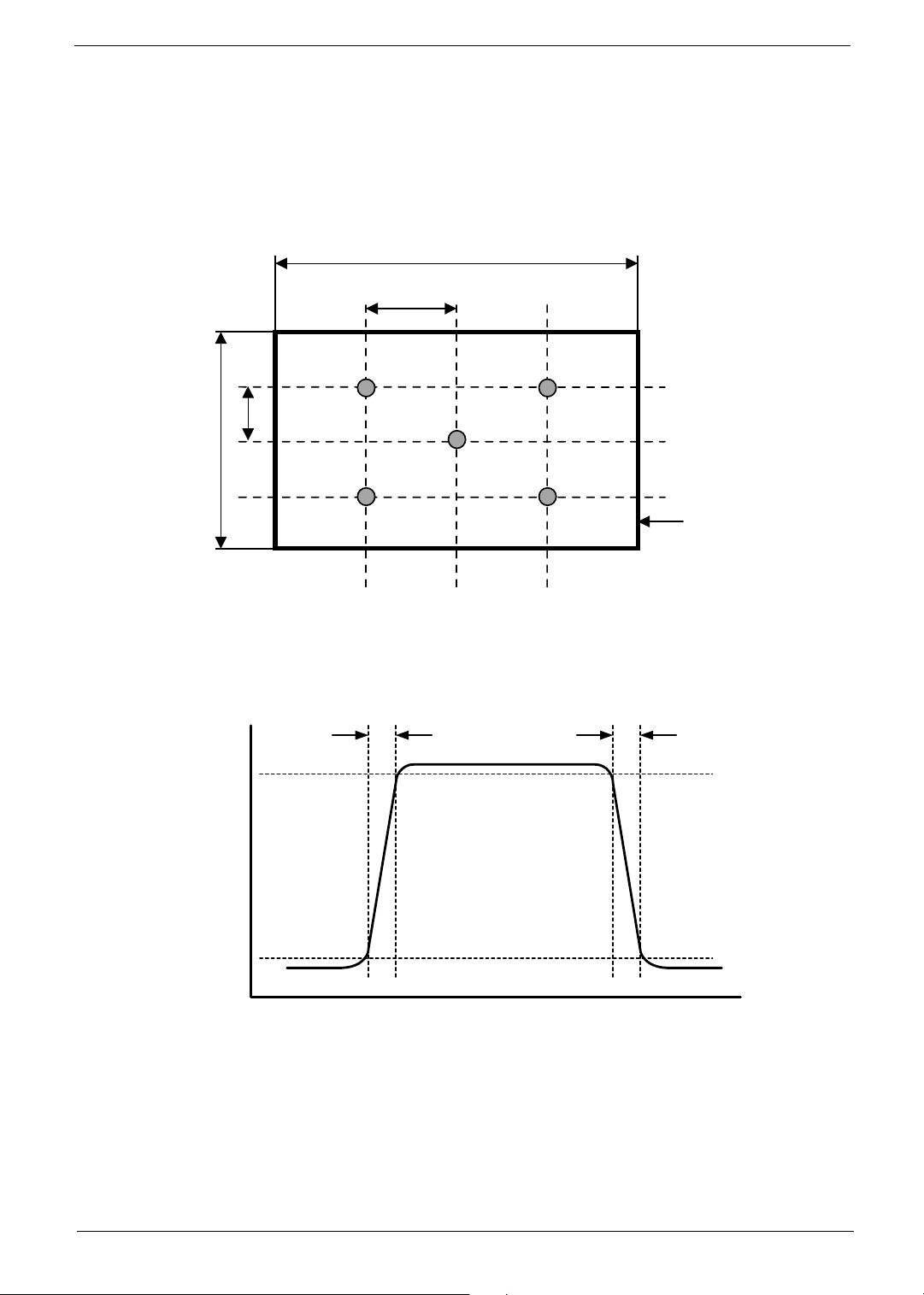
NOTE: The variation in surface luminance, WHITE is defined by measuring LON at watch test position 1
a
through 5, and then dividing maximum LON of 5 points luminance by minimum LON of each 5 points
luminance.
WHITE = Maximum(LON1, LON2,....,LON5)/Minimum(LON1, LON2,....,LON5)
δ
δ
H
A
A: H/4 mm,
B: V/4 mm,
B
L3 L2
V
L1
H: 706.90 mm
V: 397.44 mm
@ H,V: Active Area
L5 L4
NOTE: This shall be measured at center of the screen.
NOTE: Response time is the time required for the display to transition from black to white(Rise Time, TrR) and
from white to black(Decay TIme, TrD).
TrR
100
90
Active Are
TrD
Optical
Response
10
0
NOTE: Viewing angle is the angle at which the contrast ratio is greater than 10. The angles are determined for
the horizonal or x axis and the vertical or y axis with respect to the z axis which is normal to the LCD
surface.
9
Page 10

φ
= 180°, Left
φ
= 270°, Down
Normal
E
Y
φ
= 90°, Up
θ
φ
φ
= 0°, Right
10
Page 11

Display Electrical and Functional Specifications
Input and Output Signals
This LCD TV shall have the ability to operate under following range with stable green color of LED indicated.
Any signal outside of the limits(any combination) shall not cause any damage to the unit or driving source. The
range of operations is:
T CVBS and Y/C
NTSC(3.58M), NTSC(4.43M), Japan(50Hz)
PAL(4.43M, 50 Hz) B, G, D, K, H, I, PAL(4.43M, 60 Hz)
SECAM D, K
T TV Systems
NTSC-M/USA(3.58M) system Receivable
VHF/UHF/CATV, 181 channels auto-present tuning
Full frequency range from channel 2(55.25 MHz) to channel 69(801.25MHz)
T YUV inputs:
YCbCr: 480i/576i
YPbPr: 480p/576p, 1080i, 720p
T VGA and DVI-D inputs
Horizontal input frequency range: 30KHz to 70KHz
Vertical input frequency range: 56Hz to 85 Hz
Max. Resolution: 1280 x 768
Down Scaling support 1152x 870 75Hz
1280 x 960 60/85Hz
1280 x 1024 60/75/85 Hz
The LED shall indicate green color and OSD will show “Out of Range” message within 5 seconds after signal
is out of range or down scaling support selected input.
This LCD TV shall catch signal sources from TV, AV1, AV2, AV3, AV4, VGA and DVI-D automatically during
power up, which it is unnecessary to select inputs from OSD or hot keys.
The priority to catch signal sources shall be 1
rd
used, 3
input, 7
) TV input(last power down channel), 4 th) AV1 YUV input, 5 th) AV1 S-video input, 6th) AV1 CVBS
th
) AV2 YUV input, 8th) AV2 S-video input, 9th) AV2 CVBS input, 13th) VGA input, 14th)DVI-D input. THe
LCD TV shall complete selection and show media on screen within 5 seconds(including Auto Adjust)
The LED shall indicate green color and OSD will show “No Signal” within 3 seconds while there is missing
signal from selected input.
The LED shall indicate green color and OSD will show “No VGA Connection” within 5 seconds whild VGA input
is selected but has no connection on VGA port.
The LED shall indicate green color and OSD will show “Go Into Power Save” within 5 seconds after meet
condition of power saving mode.
This LCD TV shall go into power saving state in 5 seconds later of showing” Go Into Power Save”. THe LED
shall indicate amber color during power saving mode.
This LCD TV shall proceed Auto Adjust while VGA or DVI-D input is selected and1)Power up, 2) Auto Adjust
pressed from OSD, 3) Factory preset acted, 4) New mode is detected. Auto adjust shall be completed within 3
seconds.
The AV1 input supports YUV(YCbCr and YPbPr), S-video and CVBS video inputs, If the YUV, S-video and
CVBS video inputs are connected with cables, the priority shall be 1
video input.
st
) User selected source from hot key or OSD, 2 nd) Last soutce
st
)YUV input, 2nd)S-video input, 3rd) CVBS
11
Page 12

The AV2 input supports YUV(YCbCr and YPbPr), S-video and CVBS video inputs, If the YUV, S-video and
CVBS video inputs are connected with cables, the priority shall be 1
st
)YUV input, 2nd)S-video input, 3rd) CVBS
video input.
The AV3 could be set either input or output from OSD. Whild it is set to be output, AV3 would carry CVBS
signal and stereo audio out from TV tuner.
The AV4 input supports both of S-video adn YUV(YCbCr and YPbPr) input. IF both of the S-video and YUV
inputs are connected with cables, the YUV takes priority.
Video Input
CVBS Input Signal
T Type: Analog
T Polarity: Positive
T Level: 1 Vp-p(with Sync.)
T Impedance: 75 +/- 5%
T Interface: RCA Jack, Yellow color
Ω
S-Video Input Signal
T Type: Analog
T Polarity: Positive
T Level: Y:1 Vp-p(with Sync.) C: 0.286 Vp-p
T Impedance: 75 +/- 5%
T Interface: S-Din, Black color
Ω
YUV(YCbCr or YPbPr) Input Signal
T Type: Analog
T Polarity: Positive
T Level: Y:1 Vp-p(with sync) U/V:0.7 Vp-p
T Impedance: 75 +/- 5%
T Interface: RCA Jack, Y: Green color, U: Blue color, V: Red color
Ω
Audio input, output and Speaker
Audio input
T Level: 500 m Vrms
T TYpe: Stereo R/L Channels
T Impedance: More than 22 K
T Interface: RCA Jack, R:Red color, L:White color
PC Stereo Input
T Level: 500m Vrms
T Type: Stereo R/L Channels
T Impedance: More than 22 K
12
Ω
Ω
Page 13

T Interface: RCA Jack, R:Red color, L: White color
Audio Line Output
T Level: 400 m Vrms
T Type: Stereo R/L Channels
T Interface: 3.5mm Stereo jack
Earphone Output
T Level: 0.5W/per Channel(typ) for 16 earphone
T Type: Stereo R/L Channels
T Interface: 3.5mm Stereo jack, Pantone 157C, Orange color
Built-in Speaker
T Max. Audio output(at 10% THD max.) at 1.0 Vp-p/1KHz input: 10W +10W
T Sound Distortion at 250mW/1KHz:1% THD max
T Speaker: 20W(10W+10W)
T Speaker impedance: 4 at 1KHz
T Residual Hum at Min. Volume: 500 uW Max.
T Max. Hum at Max. Volume: 1000 uW Max.
Ω
Ω
13
Page 14

RF Input
Intermediate Frequencies
No SYSTEM NTSC-M/USA UNIT
1 Picture Intermediate Frequency 45.75 MHz
2 Colour 42.17 MHz
3 Sound Carrier 41025 MHz
Channel Coverage
No BAND FREQUENCY
1 Low band 55.25 to 160.00 MHz
2 Mid band 160.00 to 442.00 MHz
3 High band 442.00 to 801.25 MHz
Video and Audio Characteristics
No Parameter MIN TYP MAX UNIT
1 Video output level
2 4448- dB
3 - 44 49 dBuV
4 Video amplitude frequency
5 Audio output level 140 290 440 mVr
6 Audio S/N 40 48 - dB
Video S/N
Noise limiting sensitivity
characteristics
0.8 1.0 1.2 Vp-p
1.0 MHz -2.0 0 +2.0
2.0 MHz -2.0 0 +2.0
3.0 MHz -3.0 -0.5 +2.0
4.0 MHz -4.5 -1.5 +1.5
dB
ms
VGA Input
Separate and Composite Sync
T Level: Low: 0 ro 0.8V High: 2.0 to 5V
T Polarity: Positive or Negative
T Impedance: 1K or higher
R.G.B Input Signal(comply with VESA VSIS, Ver.1, Rev.1)
T Level: 0 to 700 mV Positive
T Rise/Fall time: <= 5 ns
T Overshoot: <= 10% of maximum transition
T Impedance: 75 % from DC up to 100 MHz
Current Sink and Source
When low level is asserted, the maximum current sink from any single monitor sync input node to the driver is
2.0mA. When high level is asserted, the maximum current source from the driver to any single monitor sync
input node is 500 uA.
14
Ω
Ω 5±
Page 15

Sync. On Green (SOG)
T Level: 300mV
T Polarity: Negative
T Impedance: 1K or higher
Ω
D-Sub Pin Out(Pantone 661C, Blue color)
PIN Signal PIN Signal
1 Red Video 9 +5V
2 Green Video 10 VGA-CONN(Sync GND)
3 Blue Video 11 Ground
4 Ground 12 SDA (DDC Data)
5 Ground 13 Horizontal Sync
6 Red Ground 14 Vertical Sync
7 Green Ground 15 SCL(DDC Clock)
8 Blue Ground
DVI-D Input
15
Page 16

PIN Signal PIN Signal
1 TMDS Data 2- 13 TMDS Data
2 TMDS Data 2+ 14 +5V POWER
3 TMDS Data 2/4 shield 15 Grond(For +5 V)
4 TMDS Data 4- 16 Hot Plug Detect
5 TMDS Data 4+ 17 TMDS Data 0-
6 DDC Clock 18 TMDS Data 0+
7 DDC Data 19 TMDS Data 0/5 shield
8 No Connect 20 TMDS Data 5-
9 TMDS Data 1- 21 TMDS Data 5+
10 TMDS Data1+ 22 TMDS Clock shield
11 TMDS Data 1/3 shield 23 TMDS Clock+
12 TMDS Data 3- 24 TMDS Clock-
Terminals Configuration
Ter min al Configuration
RF
AV1 RCA jack for Video, YUV and Audio; S-Din for S-video
AV2 RCA jack for Video, YUV and Audio; S-Din for S-video
AV4 RCA jack for YUV and Audio; S-Din for S-video
AV3 RCA jack for Video and Audio (In/Out selected by OSD)
PC Analog Port D-Sub 15 pin
PC Stereo input
Audio Line Out
Earphone Out
PC Digital Port DVI-D/HDCP
Service Port ISP through D-Sub
Ω
75 Unbalance F Type connector
φ
3.5mm Earphone Jack
φ
3.5mm Earphone Jack
φ
3.5mm Earphone Jack
16
Page 17

TV System
TV System Configuration
Item Configuration
Destination USA, Canada, Philippines, Korea, Taiwan...
Color System NTSC
Sound System M
Stereo System BTSC/A2
Channel System USA( Standard, IRC and HRC) Full frequency range from ch
De-interlace and Filter
The De-interlace Processor of this LCD TV shall be pixel-based motion and edge adaptive de-interlacing
which converts multiple(interlaced) video fields into a single(progressive scan)video frame with twice the
number of active scan lines as each of the source fields.
The LCD TV also can detect the input video source sequence automatically. Two types of progressive scan
source sequencing can be detected, i.e. 2:2 pull down and 3:2 pull down.
This LCD TV shall have motion adaptive 3D digital Y/C separation improves the lumachroma separation
process such that the luma and chroma are perfectly separated for a stationary image.
This LCD TV shall adopt a motion adaptive filter based noise reduction to successfully determine the change
among frames resulting from noise or moving object.
A2 to ch A69
Firmware Specifications
Preset Mode for VGA and DVI-D Inputs
16 factory pre-set modes for VGA and DVI-D inputs are saved during the manufacturing process.
Preset
mode
1 720*400 31.47 - 70 + VGA
2 640*480 31.47 - 60 - VGA
3 640*480 37.861 - 72 - VESA
4 640*480 37.861 - 75 - VESA
5 640*480 43.4 -
6 800*600
7 800*600 37.879 + 60 + VESA
8 800*600 48.077 + 72 + VESA
9 800*600 46.875 + 75 + VESA
10 800*600 53.7 + 85 + VESA
11 1024*768 48.363 - 60 - VESA
12 1024*768 56.476 - 70 - VESA
13 1024*768 60.023 + 75 + VESA
14 1024*768 68.7 + 85 + VESA
15 832*624 49.7 - 75 - MAC
Pixel
Format
Hor. Freq.(kHz)
35.156 - 56
Hor.
Polarity
85
Vert. Freq.(Hz)
Vertical
Polarity
- VESA
+ VESA
Standard
17
Page 18

Preset
mode
16 1024*768 60.2 - 75 - MAC
Pixel
Format
Hor. Freq.(kHz)
Hor.
Polarity
Vert. Freq.(Hz)
Vertical
Polarity
Standard
This LCD TV shall have 10 or more user modes for user to creat own timing.
This LCD TV would detect the used mode automatically.
Power Saving
While VGA or DVI-D is selected to be input, this LCD TV is equipped with a power management according to
VESA DPMS. There is a delay of 5 seconds before the transition from On-state to power saving state to avoid
unintentionally entering of a power saving state during display resolution and timing mode changes. During the
period of delay, the LED shall indicate green color and OSD will show “ GO INTO POWER SAVE”. Transition
from any power saving state to another can be instantaneous. The recovery from Off-state requires no manual
power on.
Mode Hsync Vsync Video Power Indication
Power on On On Active <210W Green --
Stans-by Off On Off <5W Amber <3s
Suspend On Off Off <5W Amber <3s
Off-state Off Off Off <5W Amber <3s
Power off X X X <5W Dark Turn on <
Recovery
Time
5s
Sync on means: normal operation
Sync off means: Hysnc: f<1 KHz, duty cycle > 255, Vsync: f<10 Hz, duty cycle >25%
The power-consumption is valid over the specified voltage and frequency range.
Power comsuption is measured from AC source.
There are no power saving modes for TV, AV1, AV2 AV3 and AV4 inputs.
VESA DDC
The VGA and DVI-D inputs shall be capable of continuously transmitting its Extended Display
Identification(EDID) information using Display Data Channel. It shall automatically switch to DDC2 mode if a
DDC2 capable host is detected in accordance with the VESA DDC standard.
In addition, the display can respond to a request for EDID, to be transmitted using DDC2, level B commands.
If a DDC2 capable host is detected by the display, the display shall switch to DDC2 communication.
The EDID shall contain the manufacture name code QCI, product code, date of manufacture, and serial
number.
For complete EDID data structure, please refer to VESA Extended Display Idenrification
Data Standard.
Hardware inplementation may be either intergrate into micro-controller or be a separate electrical component.
EDID memory must be protected against writing or other corruption through customer-accessible electrical
connection and required communication channels. Password protection, use of an unpublished enable
register, or use of direct electrical connection is acceptable levels of protection provided that the power-on
Default State is that disabling writing. The serial number fields in the EDID must contain a unique identifying
numbers among units of the same model. EDID Table is defined as below:
18
Page 19

VGA input
0 1 2 3 4 5 6 7 8 9 A B C D E F
0 00 FF FF FF FF FF FF 00 09 EE 80 0C 00 00 00 00
1 2D 0E 01 03 68 47 28 78 E8 28 C1 A4 57 46 9D 25
2 14 47 4B AF EE 00 31 59 45 59 61 59 00 00 00 00
3 00 00 00 00 00 00 66 21 50 B0 51 00 1B 30 40 70
4 36 00 C6 90 21 00 00 1E 00 00 00 FD 00 32 55 1E
5 50 08 00 0A 20 20 20 20 20 20 00 00 00 FC 00 42
6 54 56 42 33 32 55 53 0A 20 20 20 20 00 00 00 FC
7 00 42 54 56 42 33 32 55 53 0A 20 20 20 20 00 1A
DVI-D input
0 1 2 3 4 5 6 7 8 9 A B C D E F
0 00 FF FF FF FF FF FF 00 09 EE 80 0C 00 00 00 00
1 2D 0E 01 03 E8 47 28 78 E8 28 C1 A4 57 46 9D 25
2 12 47 4B AF EE 00 31 59 45 59 61 59 00 00 00 00
3 00 00 00 00 00 00 66 21 50 B0 51 00 1B 30 40 70
4 36 00 C6 90 21 00 00 1E 00 00 00 FD 00 32 55 1E
5 50 08 00 0A 20 20 20 20 20 20 00 00 00 FC 00 42
6 54 56 42 33 32 55 53 0A 20 20 20 20 00 00 00 FC
7 00 42 54 56 42 33 32 55 53 0A 20 20 20 20 00 9A
Control Button
POWER Software On/Off
MENU/EXIT Press this button to open the OSD or Enter function
CH
or
CH
VOL
VOL
INPUT Press this button to select the input:
Key Function
When OSD is on:
Press
Press
key to move icon to up position
key to move icon to down position
When OSD is off:
Press these buttons to select the TV channel in sequence.
When OSD is on:
Press key to increase value or move icon to right position
or
Press key to decrease value or move icon to left position
When OSD is off:
Press these buttons to select the volume level.
TV AV1 AV2 AV3 AV4 VGA DVI
19
Page 20

Remote controller
20
Key Name Key Functions
POWER Power on/off
INPUT Change the input source. TV/AV1/AV2/AV3/AV4/VGA/
DVI-D
INFO Display channel and source/Disable display
CH+ Channel up
CH- Channel down
VOL+ Volume up
VOL- Volume down
MUTE Mutes or restores the sound volume
TV Direct access of TV input
AV1 Direct Access of AV1 input
AV2 Direct Access of AV2 input
AV3 Direct Access of AV3 input
YPbPr
VGA Direct Access of VGA input
Direct Access of YPbPr input
PIP/Dual Pictures
Selected
YPbPr/VGA/DVI-D
Page 21

Key Name Key Functions
DVI Direct Access of DVI input
MTS Multi channel Television Soune(MTS)- Cycles through
Stereo, MONO and SAP
LAST Recalls the last viewed channel
0-9 Number keys
SLEEP Turns on the sleep timer- Off/30/60/90/120
MENU Displays menus for TV and other options
WIDE Selects the picture format(16:9, 4:3, LETTERBOX,
PANORAMA)that best meets your viewing requirement
PIP Turns picture-in-picture(PIP) mode on and off
CH SCAN Scans four channels at a time in TV mode
FREEZE Freezes the display image
UP ARROW Navigate up in the OSD
DOWN ARROW Navigate down in the OSD
LEFT ARROW Navigate left in the OSD
RIGHT ARROW Navigate right in the OSD
OK Accept the selected item in the OSD
EXIT Exits from the on-screen display(OSD)
C.C. Turns CLOSED CAPTION mode on and off
PIP/Dual Pictures
Selected
Sound System
The System has a feature that allows reception of sound other than the main audio for the program.
This feature is called Multi-channel Television sound(MTS). The System with MTS can receive MONO sound,
STEREO sound and Secondary Audio Programs(SAP). The SAP feature allows a TV station to broadcast
other information, which could be audio(MONO) in another language or something completely different like
weather information.
The inages display examples when receiving MTS and SAP are as follows:
Input Sound Mode MTS Key Pressed
Stereo Mode Stereo Mono
Main + SAP Mode Main SAP Dual
Stereo + SAP Mode Stereo SAP Mono
Mono Mode Mono Mono
21
Page 22

T Stereo broadcasts
View programs like live sporting events, shows and concerts in dynamic stereo sound.
T SAP broadcasts
Receive TV broadcasts in either MAIN or SAP sound.
MAIN sound: The normal program soundtrack(either in mono or stereo)
SAP sound: Listen to second language, supplementary commentary and other information.(SAP is
mono sound)
T Once “MONO” mode is selected
The sound remains mono even if the system receives a stereo broadcast. You must switch
the mode back to “STEREO” if you want to hear stereo sound again.
T Selecting MTS
while in the input mode does not change the type of sound. In this case, sound is determined by
the video source.
View Mode
Panorama ( 4 : 3 strech ):
This mode is for 4 : 3 input picture. It is stretched to full-screen.
The picture is progressively stretched from the center third of the screen
outwards to the edges.
16 : 9 ( Full screen ):
Will display the picture at full screen with linear scaling.
4 : 3 :
Will display a 4 : 3 input picture at its standard. 4 : 3 size without any
stretching. Black stripes will be visible down theleft and right sides of the
picture.
16 : 9 Cinema ( Letter Box ):
This is useful for simulated 16 : 9 formate from DVD player. Select this
view mode to have over screen. Default to stretches 1.85:1 picture format
to full screen. (Note: For 2.35:1 picture format, there will still be a small
black band on the top and bottom on the screen.)
There shall have view mode information shown on top-left corner for around 10 seconds while change view
mode from remote controller.
If input picture is 4:3 format in video source, user can have the following view mode selections:
Auto: It can be Panorama(4:3 strech) or 4:3 view mode depending on 4:3 auto picture setting in OSD menu.
22
Page 23

16:9 Cinema
4:3
16:9(full-screen)
If input source is in PC source, user can have the following view mode selections:
Full screen(16:9)
Aspect ratio: To keep the same aspect ration as input picture
23
Page 24

Multi Picture
Press Source key to Select
Input
Duel Picture
Step 1: Press PIP key once to display duel picture as left
side.
Step 2: Press Source key to or input channel number for
2nd media.
The screen would be as right side.
Picture in Picture
Step 1: Press PIP key twice to display picture in picture
as left side.
Step 2: Press Source key or input channel number for 2nd
media. Please refer to right figure.
Channel Scan
Press Scan key once in TV or CATV mode to active
channel scan. This TV would start to scan channels from
original channel.
Press Scan key once again to stop channel scan and
return to main source.
Freeze
Press Freeze key to freeze screen.
Press Freeze key again to release it.
As left figure, froze screen would be on left side and
remain lived screen on right side.
There are two source groups, group 1 including TV, AV1, AV2, AV3 and YCbCr, group 2
including YPbPr, VGA and DVI-D. Multi picture function is available for different group
source only.
Ex. TV could have picture and picture to YPbPr, VGA or DVI-D.
TV could not have PIP function to AV1, AV2, AV3 and YCbCr
Page 25

Performance Specifications
The performance shall be check at 25oC environment.
White Balance and Uniformity
Set contrast and brightness at maximum.
Standard: 10000 degree K, +/- 0.03 on x and y value.
Warm: 6500 degree K, +/- 0.03 on x and y value.
Cold: 14000 degree K, +/- 0.03 on x and y value.
Display Area, Phase, Center and Tilt
Display Area: 43 inches diagonal
H-Ohase: | A-B | Less than 1.5 mm
V-Center: | C-D | Less than 1.5 mm
Tilt: | E-F| Less than 1 mm
E
F
C
A
B
D
Max. Brightness
The brightness should exceed 350 Cd/m2 whild set both of contrast and brightness to max. and color
temperature of Standard is selected.(Typical value would be 500 Cd/m
Acoustical Noise
With the display operation, the sound measured is following ISO-7779 and shall be less than 35 dB/A in
standard distance of 1m. Also, the display should not emit easily perceptible abnormal sounds.
2
)
Power Supply Electrical Specifications
The power supply for this product is ans internal converter, with a non-replaceable fuse internally.
This converter shall be well designed to meet CE mark requirement.
Input Voltage and Frequency Range
The operating range of line voltage shall be:
AC90 volts to 264 volts, 46 Hz to 63 Hz
Power comsuption shall be under 210 Watts
variation of th line voltage throughout the applicable operating range shall not result in any visible image
anomalies such as image movement, changes in light output, nor changes in image stability or quality.
Line Fuse
The AC input shall be fused and become electrically open as a result of an unsafe current condition. This fuse
is inside the power supply converter and is not user replaceable, and must be returned for replacement.
24
Page 26

This fuse shall be well selected to handle inrush current for all combinations of line voltage and frequency.
Hot plug and power on/off sequence
Once hot plug occurs, at the very first time, the initial current should be limited at 2.3 amps or liser when power
off. current sill stay below 100m amps while power on, then ramp up to full power(about 2.3 amps at AC 120
volts) within 5 seconds when power-up signal is triggered. For the shut down sequence, the current will stay at
full power for about 150m seconds or less, then ramp down to 100 m amps within 1 second.
Power on LED Location and Type
Inverter
This inverter which is used to light up back-light of LCD panel shall be well designed to meet requirement of
panel’s specification.
25
Page 27

Accessories
Cables
Power Cord
T Length: 1.8 meters+15mm/-0 mm
T Cable Color: Black
T Quantity: one
AV(Euro-SCART) Cable
T Length: 1.8 meters+15mm/-0 mm
T Cable Color: Black
T Quantity: one
TV Antenna Cable
T Length: 12.5 meters+15mm/-0 mm
T Cable Color: transparent
T Quantity: one
Remote Controller
T Multi-function remote controller
T With two AAA battery inside
T Quantity: One
I/O Board (Reserved)
Others
T one remote controller users guide
T warranty card
26
Page 28

Physical Dimensions
Overall Dimension
Height: 620.40 mm
Width: 821.30 mm
Depth: 210.50 mm
Base
Swivel: 40o (R: 20o, L: 20o)
Mass
Mass of display with cable approx.: 20.g Kg
VESA Mounting Holes
According to Vesa FPMPMI standard.
4 holes 100 mm x 100 mm (4 mm, 0.7 pitch threaded) in the rear center for ARM
4 holes 200 mm x 100 mm (4 mm, 0.7 pitch threaded) in the rear center for ARM
27
Page 29

Regulatory and Reliability Requirements
Regulatory Requirements
Product Safety Agency Approvals
this display unit complies with following safety standards.
UL compliance: UL6500 for Audio, Video and similar electronic apparatus.
CSA compliance(or cUL) : CAN/CSA E60065-00 for Audio, Video and similar electronic apparatus.
Emissions/Susceptibility
This display unit complies with the following EMC regulations
FCC compliance: Subpart 15 B of DoC
ICES03 compliance
Environment Requirements
This display shall meet the following environmental requirements under normal operating conditions
Operating
oo
25
measurement
operation temperature: 0
Operating humidity: 10% to 90%(non-condensing)
for Purity, White Point, Mis-convergence, Luminance measurements and White uniformity
5±
o
C to 35oC
Storage and Shipping
T Sotrage temperature: -20
T Shipping temperature: -20
T Storage humidity: 10% to 90%(non-condensing)
T Shipping humidity: 10% to 90%(non-condensing)
o
C to 60oC
o
C to 60oC
Altitude
Units tested at an altitude up to 12000 feet must operate at normal conditions without exhibiting abnormal
behavior such as arcing or shutdown.
T Operating altitude: 0 to 12000 feet
T Shipping altitude: 0 to 40000 feet
T Storage altitude: 0 to 40000 feet
28
 Loading...