

Page 1

Aspire one Series
Service Guide
Service guide files and updates are available
on the ACER/CSD web; for more information,
please refer to http://csd.acer.com.tw
PRINTED IN TAIWAN
Page 2

Revision History
Please refer to the table below for the updates made on Aspire one Series service guide.
Date Chapter Updates
II
Page 3

Copyright
Copyright © 2008 by Acer Incorporated. All rights reserved. No part of this publication may be reproduced,
transmitted, transcribed, stored in a retrieval system, or translated into any language or computer language, in
any form or by any means, electronic, mechanical, magnetic, optical, chemical, manual or otherwise, without
the prior written permission of Acer Incorporated.
Disclaimer
The information in this guide is subject to change without notice.
Acer Incorporated makes no representations or warranties, either expressed or implied, with respect to the
contents hereof and specifically disclaims any warranties of merchantability or fitness for any particular
purpose. Any Acer Incorporated software described in this manual is sold or licensed "as is". Should the
programs prove defective following their purchase, the buyer (and not Acer Incorporated, its distributor, or its
dealer) assumes the entire cost of all necessary servicing, repair, and any incidental or consequential
damages resulting from any defect in the software.
Acer is a registered trademark of Acer Corporation.
Intel is a registered trademark of Intel Corporation.
Pentium and Pentium II/III are trademarks of Intel Corporation.
Other brand and product names are trademarks and/or registered trademarks of their respective holders.
III
Page 4
Conventions
The following conventions are used in this manual:
SCREEN MESSAGES Denotes actual messages that appear
on screen.
NOTE Gives bits and pieces of additional
information related to the current
topic.
WARNING Alerts you to any damage that might
result from doing or not doing specific
actions.
CAUTION Gives precautionary measures to
avoid possible hardware or software
problems.
IMPORTANT Reminds you to do specific actions
relevant to the accomplishment of
procedures.
IV
Page 5

Preface
Before using this information and the product it supports, please read the following general information.
1. This Service Guide provides you with all technical information relating to the BASIC CONFIGURATION
decided for Acer's "global" product offering. To better fit local market requirements and enhance product
competitiveness, your regional office MAY have decided to extend the functionality of a machine (e.g.
add-on card, modem, or extra memory capability). These LOCALIZED FEATURES will NOT be covered
in this generic service guide. In such cases, please contact your regional offices or the responsible
personnel/channel to provide you with further technical details.
2. Please note WHEN ORDERING FRU PARTS, that you should check the most up-to-date information
available on your regional web or channel. If, for whatever reason, a part number change is made, it will
not be noted in the printed Service Guide. For ACER-AUTHORIZED SERVICE PROVIDERS, your Acer
office may have a DIFFERENT part number code to those given in the FRU list of this printed Service
Guide. You MUST use the list provided by your regional Acer office to order FRU parts for repair and
service of customer machines.
V
Page 6

VI
Page 7

Table of Contents
System Specifications 1
Features . . . . . . . . . . . . . . . . . . . . . . . . . . . . . . . . . . . . . . . . . . . . . . . . . . . . . . . . . . . .1
System Block Diagram . . . . . . . . . . . . . . . . . . . . . . . . . . . . . . . . . . . . . . . . . . . . . . . . .3
Your Acer Notebook tour . . . . . . . . . . . . . . . . . . . . . . . . . . . . . . . . . . . . . . . . . . . . . . .4
Front View . . . . . . . . . . . . . . . . . . . . . . . . . . . . . . . . . . . . . . . . . . . . . . . . . . . . . . .4
Closed Front View . . . . . . . . . . . . . . . . . . . . . . . . . . . . . . . . . . . . . . . . . . . . . . . . .5
Left View . . . . . . . . . . . . . . . . . . . . . . . . . . . . . . . . . . . . . . . . . . . . . . . . . . . . . . . .5
Right View . . . . . . . . . . . . . . . . . . . . . . . . . . . . . . . . . . . . . . . . . . . . . . . . . . . . . . .6
Rear View . . . . . . . . . . . . . . . . . . . . . . . . . . . . . . . . . . . . . . . . . . . . . . . . . . . . . . .6
Bottom View . . . . . . . . . . . . . . . . . . . . . . . . . . . . . . . . . . . . . . . . . . . . . . . . . . . . .7
Indicators . . . . . . . . . . . . . . . . . . . . . . . . . . . . . . . . . . . . . . . . . . . . . . . . . . . . . . .7
TouchPad Basics . . . . . . . . . . . . . . . . . . . . . . . . . . . . . . . . . . . . . . . . . . . . . . . . .8
Using the Keyboard . . . . . . . . . . . . . . . . . . . . . . . . . . . . . . . . . . . . . . . . . . . . . . . . . . .9
Lock Keys and embedded numeric keypad . . . . . . . . . . . . . . . . . . . . . . . . . . . . .9
Hot Keys . . . . . . . . . . . . . . . . . . . . . . . . . . . . . . . . . . . . . . . . . . . . . . . . . . . . . . .10
Special Key . . . . . . . . . . . . . . . . . . . . . . . . . . . . . . . . . . . . . . . . . . . . . . . . . . . . .11
Hardware Specifications and Configurations . . . . . . . . . . . . . . . . . . . . . . . . . . . . . . .12
System Utilities 19
BIOS Setup Utility . . . . . . . . . . . . . . . . . . . . . . . . . . . . . . . . . . . . . . . . . . . . . . . . . . . .19
Navigating the BIOS Utility . . . . . . . . . . . . . . . . . . . . . . . . . . . . . . . . . . . . . . . . .19
Information . . . . . . . . . . . . . . . . . . . . . . . . . . . . . . . . . . . . . . . . . . . . . . . . . . . . .20
Main . . . . . . . . . . . . . . . . . . . . . . . . . . . . . . . . . . . . . . . . . . . . . . . . . . . . . . . . . .21
Security . . . . . . . . . . . . . . . . . . . . . . . . . . . . . . . . . . . . . . . . . . . . . . . . . . . . . . . .22
Boot . . . . . . . . . . . . . . . . . . . . . . . . . . . . . . . . . . . . . . . . . . . . . . . . . . . . . . . . . . .25
Exit . . . . . . . . . . . . . . . . . . . . . . . . . . . . . . . . . . . . . . . . . . . . . . . . . . . . . . . . . . .26
BIOS Flash Utility . . . . . . . . . . . . . . . . . . . . . . . . . . . . . . . . . . . . . . . . . . . . . . . . . . . .27
Remove HDD/BIOS Utility . . . . . . . . . . . . . . . . . . . . . . . . . . . . . . . . . . . . . . . . . . . . .29
Machine Disassembly and Replacement 33
Disassembly Requirements . . . . . . . . . . . . . . . . . . . . . . . . . . . . . . . . . . . . . . . . . . . .33
Related Information . . . . . . . . . . . . . . . . . . . . . . . . . . . . . . . . . . . . . . . . . . . . . . .33
General Information . . . . . . . . . . . . . . . . . . . . . . . . . . . . . . . . . . . . . . . . . . . . . . . . . .34
Pre-disassembly Instructions . . . . . . . . . . . . . . . . . . . . . . . . . . . . . . . . . . . . . . .34
Disassembly Process . . . . . . . . . . . . . . . . . . . . . . . . . . . . . . . . . . . . . . . . . . . . .34
External Module Disassembly Process . . . . . . . . . . . . . . . . . . . . . . . . . . . . . . . . . . .35
External Modules Disassembly Flowchart . . . . . . . . . . . . . . . . . . . . . . . . . . . . .35
Removing the Battery Pack . . . . . . . . . . . . . . . . . . . . . . . . . . . . . . . . . . . . . . . .36
Removing the 3G Cover . . . . . . . . . . . . . . . . . . . . . . . . . . . . . . . . . . . . . . . . . . .37
Removing the Keyboard . . . . . . . . . . . . . . . . . . . . . . . . . . . . . . . . . . . . . . . . . . .38
Removing the Upper and Lower Covers . . . . . . . . . . . . . . . . . . . . . . . . . . . . . . .39
LCD Module Disassembly Process . . . . . . . . . . . . . . . . . . . . . . . . . . . . . . . . . . . . . .41
LCD Module Disassembly Flowchart . . . . . . . . . . . . . . . . . . . . . . . . . . . . . . . . .41
Removing the LCD Module . . . . . . . . . . . . . . . . . . . . . . . . . . . . . . . . . . . . . . . . .42
Removing the LCD Bezel . . . . . . . . . . . . . . . . . . . . . . . . . . . . . . . . . . . . . . . . . .44
Removing the Camera Board . . . . . . . . . . . . . . . . . . . . . . . . . . . . . . . . . . . . . . .45
Removing the MIC Board . . . . . . . . . . . . . . . . . . . . . . . . . . . . . . . . . . . . . . . . . .46
Removing the LCD Panel . . . . . . . . . . . . . . . . . . . . . . . . . . . . . . . . . . . . . . . . . .47
Removing the LCD Brackets and FPC Cable . . . . . . . . . . . . . . . . . . . . . . . . . . .48
Main Unit Disassembly Process . . . . . . . . . . . . . . . . . . . . . . . . . . . . . . . . . . . . . . . . .50
Main Unit Disassembly Flowchart . . . . . . . . . . . . . . . . . . . . . . . . . . . . . . . . . . . .50
Removing the WLAN Module . . . . . . . . . . . . . . . . . . . . . . . . . . . . . . . . . . . . . . .51
Removing the USB/LED/Power/Card Reader Board . . . . . . . . . . . . . . . . . . . . .52
Removing the SSD Module . . . . . . . . . . . . . . . . . . . . . . . . . . . . . . . . . . . . . . . . .53
VII
Page 8

Table of Contents
Removing the Mainboard . . . . . . . . . . . . . . . . . . . . . . . . . . . . . . . . . . . . . . . . . .55
Removing the Speaker Module . . . . . . . . . . . . . . . . . . . . . . . . . . . . . . . . . . . . . .56
Removing the Hard Disk Drive Module . . . . . . . . . . . . . . . . . . . . . . . . . . . . . . . .58
Removing the DIMM Module . . . . . . . . . . . . . . . . . . . . . . . . . . . . . . . . . . . . . . .60
Removing the Thermal Module . . . . . . . . . . . . . . . . . . . . . . . . . . . . . . . . . . . . . .61
LCD Module Reassembly Procedure . . . . . . . . . . . . . . . . . . . . . . . . . . . . . . . . . . . . .63
Replacing the LCD Brackets and FPC Cable . . . . . . . . . . . . . . . . . . . . . . . . . . .63
Replacing the LCD Panel . . . . . . . . . . . . . . . . . . . . . . . . . . . . . . . . . . . . . . . . . .64
Replacing the Mic Board . . . . . . . . . . . . . . . . . . . . . . . . . . . . . . . . . . . . . . . . . . .65
Replacing the Camera Board . . . . . . . . . . . . . . . . . . . . . . . . . . . . . . . . . . . . . . .65
Replacing the LCD Bezel . . . . . . . . . . . . . . . . . . . . . . . . . . . . . . . . . . . . . . . . . .66
Main Module Reassembly Procedure . . . . . . . . . . . . . . . . . . . . . . . . . . . . . . . . . . . . .67
Replacing the Thermal Module . . . . . . . . . . . . . . . . . . . . . . . . . . . . . . . . . . . . . .67
Replacing the DIMM Module . . . . . . . . . . . . . . . . . . . . . . . . . . . . . . . . . . . . . . . .67
Replacing the Hard Disk Drive Module . . . . . . . . . . . . . . . . . . . . . . . . . . . . . . . .68
Replacing the Speaker Module . . . . . . . . . . . . . . . . . . . . . . . . . . . . . . . . . . . . . .68
Replacing the Mainboard . . . . . . . . . . . . . . . . . . . . . . . . . . . . . . . . . . . . . . . . . .70
Replacing the SDD Module . . . . . . . . . . . . . . . . . . . . . . . . . . . . . . . . . . . . . . . . .71
Replacing the USB/LED/Power/Card Reader Board . . . . . . . . . . . . . . . . . . . . .72
Replacing the WLAN Board . . . . . . . . . . . . . . . . . . . . . . . . . . . . . . . . . . . . . . . .73
Replacing the LCM Module . . . . . . . . . . . . . . . . . . . . . . . . . . . . . . . . . . . . . . . . .73
Replacing the Upper Cover . . . . . . . . . . . . . . . . . . . . . . . . . . . . . . . . . . . . . . . . .75
Replacing the Keyboard . . . . . . . . . . . . . . . . . . . . . . . . . . . . . . . . . . . . . . . . . . .76
Replacing the 3G cover . . . . . . . . . . . . . . . . . . . . . . . . . . . . . . . . . . . . . . . . . . .77
Replacing the Battery . . . . . . . . . . . . . . . . . . . . . . . . . . . . . . . . . . . . . . . . . . . . .77
Troubleshooting 79
Common Problems . . . . . . . . . . . . . . . . . . . . . . . . . . . . . . . . . . . . . . . . . . . . . . . . . . .79
Power On Issue . . . . . . . . . . . . . . . . . . . . . . . . . . . . . . . . . . . . . . . . . . . . . . . . .80
No Display Issue . . . . . . . . . . . . . . . . . . . . . . . . . . . . . . . . . . . . . . . . . . . . . . . . .81
Random Loss of BIOS Settings . . . . . . . . . . . . . . . . . . . . . . . . . . . . . . . . . . . . .83
LCD Failure . . . . . . . . . . . . . . . . . . . . . . . . . . . . . . . . . . . . . . . . . . . . . . . . . . . . .84
Built-In Keyboard Failure . . . . . . . . . . . . . . . . . . . . . . . . . . . . . . . . . . . . . . . . . .84
TouchPad Failure . . . . . . . . . . . . . . . . . . . . . . . . . . . . . . . . . . . . . . . . . . . . . . . .85
Internal Speaker Failure . . . . . . . . . . . . . . . . . . . . . . . . . . . . . . . . . . . . . . . . . . .85
Internal Microphone Failure . . . . . . . . . . . . . . . . . . . . . . . . . . . . . . . . . . . . . . . .87
HDD Not Operating Correctly . . . . . . . . . . . . . . . . . . . . . . . . . . . . . . . . . . . . . . .88
USB Failure (Rightside) . . . . . . . . . . . . . . . . . . . . . . . . . . . . . . . . . . . . . . . . . . .89
Power Button Failure . . . . . . . . . . . . . . . . . . . . . . . . . . . . . . . . . . . . . . . . . . . . .89
External Mouse Failure . . . . . . . . . . . . . . . . . . . . . . . . . . . . . . . . . . . . . . . . . . . .90
Other Failures . . . . . . . . . . . . . . . . . . . . . . . . . . . . . . . . . . . . . . . . . . . . . . . . . . .90
Intermittent Problems . . . . . . . . . . . . . . . . . . . . . . . . . . . . . . . . . . . . . . . . . . . . . . . . .91
Undetermined Problems . . . . . . . . . . . . . . . . . . . . . . . . . . . . . . . . . . . . . . . . . . . . . . .91
Frequently Asked Questions (FAQ) . . . . . . . . . . . . . . . . . . . . . . . . . . . . . . . . . . . . . .92
POST Code Reference Tables . . . . . . . . . . . . . . . . . . . . . . . . . . . . . . . . . . . . . . . . .102
Sec: . . . . . . . . . . . . . . . . . . . . . . . . . . . . . . . . . . . . . . . . . . . . . . . . . . . . . . . . . .102
Memory: . . . . . . . . . . . . . . . . . . . . . . . . . . . . . . . . . . . . . . . . . . . . . . . . . . . . . .102
BDS & Specific action: . . . . . . . . . . . . . . . . . . . . . . . . . . . . . . . . . . . . . . . . . . .103
Each PEIM entry point used in 80_PORT . . . . . . . . . . . . . . . . . . . . . . . . . . . . .105
Each Driver entry point used in 80_PORT . . . . . . . . . . . . . . . . . . . . . . . . . . . .105
Each SmmDriver entry point used in 80_PORT . . . . . . . . . . . . . . . . . . . . . . . .108
Jumper and Connector Locations 111
Top View . . . . . . . . . . . . . . . . . . . . . . . . . . . . . . . . . . . . . . . . . . . . . . . . . . . . . . . . . .111
Bottom View . . . . . . . . . . . . . . . . . . . . . . . . . . . . . . . . . . . . . . . . . . . . . . . . . . . . . . .112
VIII
Page 9

Table of Contents
Clearing Password Check and BIOS Recovery . . . . . . . . . . . . . . . . . . . . . . . . . . . .113
Clearing Password Check . . . . . . . . . . . . . . . . . . . . . . . . . . . . . . . . . . . . . . . . .113
BIOS Recovery by Crisis Disk . . . . . . . . . . . . . . . . . . . . . . . . . . . . . . . . . . . . .114
FRU (Field Replaceable Unit) List 115
Aspire one Exploded Diagram . . . . . . . . . . . . . . . . . . . . . . . . . . . . . . . . . . . . . . . . .116
Aspire one FRU List . . . . . . . . . . . . . . . . . . . . . . . . . . . . . . . . . . . . . . . . . . . . .118
Screw List . . . . . . . . . . . . . . . . . . . . . . . . . . . . . . . . . . . . . . . . . . . . . . . . . . . . .126
Model Definition and Configuration 128
Aspire one Series . . . . . . . . . . . . . . . . . . . . . . . . . . . . . . . . . . . . . . . . . . . . . . . . . . .128
Aspire one Blue . . . . . . . . . . . . . . . . . . . . . . . . . . . . . . . . . . . . . . . . . . . . . . . . .128
Aspire one White . . . . . . . . . . . . . . . . . . . . . . . . . . . . . . . . . . . . . . . . . . . . . . . .142
Test Compatible Components 155
Linux Environment Test . . . . . . . . . . . . . . . . . . . . . . . . . . . . . . . . . . . . . . . . . . . . . .156
Aspire one Blue Testing Information . . . . . . . . . . . . . . . . . . . . . . . . . . . . . . . . .156
Aspire one White Testing Information . . . . . . . . . . . . . . . . . . . . . . . . . . . . . . . .158
Online Support Information 161
Index 163
IX
Page 10

Table of Contents
X
Page 11

System Specifications
Features
Below is a brief summary of the computer’s many feature:
Operating System
• Microsoft Windows® XP™ / Linux
Platform
• Diamondville Atrom series standard voltage 533FSB processors
• Intel 945GSE + ICH7M Chipset
System Memory
NOTE: It is not possible for end users to upgr ad e the Aspire one memory.
• One DDRII SO-DIMM slots support 512MB to 1024MB system memory
• 512MB on board memory
• 1MB Flash BIOS
Chapter 1
Display and graphics
• 8.9” Wide Screen LCD (1024x600)
• LED backlight LCD
Storage subsystem
• 8GB SSD module PATA interface
• Fixed type for 80GB or higher capacity SATA HDD
Audio
• HD audio codec
• Internal Digital MIC
Dimensions and Weight
• 248 (W) x 169.4 (D) x 29.5 (H) mm (ME dimension)
• 995g weight with 8.9” LCD and 8GB SSD
Communication
• On-Board PCI-E 10/100 LAN
• Mini-card Wireless LAN
• Wake-on-LAN suppor t
Chapter 1 1
Page 12

• 3G module through USB
Privacy control
• BIOS user, supervisor, and power on passwords
• Kensington lock slot
Power subsystem
• 2-cell 2200mAh
• 6-cell 5200mAh
• 30W 19V 3-pin AC adapter
Special keys and controls
• New Acer Aspire one keyboard support
• Power button and Wireless LAN/3G switch
I/O interface
• 2 * Express card slot
• 1 * VGA port, 15 pins
• 1 * Microphone-in/Line-in
• 1 * Line-out / Headphone out
• 3 * External USB 2.0
• 1 * DC in jack
• 1 * RJ-45 jack for LAN
• 1 * Internal Digital MIC
• 1 * 5-in-1 card reader
• 1 * SD card reader
Environment
• Temperature:
• Operating: 5 °C to 35 °C
• Non-operating: -20 °C to 65 °C
• Humidity (non-condensing):
• Operating: 20% to 80%
• Non-operating: 20% to 80%
2 Chapter 1
Page 13

System Block Diagram
Chapter 1 3
Page 14

Your Acer Notebook tour
After knowing your computer features, let us show you around your new computer.
Front View
No. Icon Item Description
1 Microphone Internal microphone for sound recording.
2 Acer Crystal Eye
Webcam
3 Power button Turns the computer on and off.
4 Wireless LAN
communication
indicator
5 Click buttons (left
and right)
6 T ouchPad Touch-sensitive pointing device which functions like
7 Keyboard For entering data into your computer.
8 Status indicators Light-Emitting Diodes (LEDs) that light up to show
9 Display screen Also called Liquid-Crystal Display (LCD), displays
Web camera for video communication (only for
certain models).
Indicates the status of wireless LAN
communication.
The left and right buttons function like the left and
right mouse buttons.
a computer mouse.
the status of the computer's functions and
components.
computer output.
4 Chapter 1
Page 15

Closed Front View
No. Icon Item Description
1 Wireless
Left View
Enables/disables the wireless function.
communication
switch
No. Icon Item Description
1 DC-in jack Connects to an AC adapter
2 External display
(VGA) port
3 Ventilation slots
and cooling fan
4 Ethernet (RJ-45)
port
5 USB 2.0 port Connect to USB 2.0 devices (e.g. USB mouse).
6Storage
expansion slot
Connects to a display device
(e.g. external monitor, LCD projector).
Enable the computer to stay cool, even after
prolonged use.
Note: Do not cover or obstruct the fan opening.
Connects to an Ethernet 10/100-based
network.
Accepts one Secure Digital (SD) card, used to
expand the capacity of My Files. Push the card
inwards and let it pop out before removing.
Note: This slot is for expanding My Files long-
term. For transferring files to and from other
devices, use the 5-in-1 card reader.
Chapter 1 5
Page 16

Right View
No. Icon Item Description
1 Microphone-in jack Accepts input from external microphones.
2 Headphones/
speaker/line-out
jack
3 USB 2.0 ports Connect to USB 2.0 devices (e.g. USB mouse).
4 Multi-in-1 card
reader
5 Kensington lock
slot
Connects to line-out audio devices
(e.g. speakers, headphones).
Accepts Secure Digital (SD), MultiMediaCard
(MMC), Memory Stick (MS), Memory S t ick PRO
(MS PRO), xD-Picture Card (xD).
Note: Push to remove/install the card. Only one
card can operate at any given time.
Connects to a Kensington-compatible computer
security lock.
Rear View
No. Icon Item Description
1 Battery bay Houses the computer’s battery pack.
6 Chapter 1
Page 17

Bottom View
No. Icon Item Description
1 Battery bay Houses the computer's battery pack.
2 Battery lock Locks the battery in position.
Battery release
latch
3 Ventilation slots
(right) and Speaker
grill (bottom)
Releases the battery for removal.
• Vents enable the computer to stay cool, even
after prolonged use.
Note: Do not cover or obstruct the cooling vents.
• Speaker grills allow audio to pass through the
casing unhindered.
Indicators
The computer has several easy-to-read status indicators. The front panel indicators are visible even when the
computer cover is closed.
Icon Function Description
Battery Indicates the computer's battery status.
HDD Indicates when the hard disk drive is active.
Num Lock Lights up when Num Lock is activated.
Caps Lock Lights up when Caps Lock is activated.
NOTE: 1. Charging: The battery light show s amber when the battery is charging. 2. Fully charged: The light
shows green when in AC mode.
Chapter 1 7
Page 18

TouchPad Basics
The following items show you how to use the TouchPad:
• Move your finger across the TouchPad (2) to move the cursor.
• Press the left (1) and right (3) buttons located beneath the TouchPad to perform selection and
execution functions. These two buttons are similar to the left and right buttons on a mouse.
Tapping on the TouchPad is the same as clicking the left button.
Function Left Button (1) Right Button (3) Main TouchPad (2)
Execute Quickly click twice. Tap twice (at the same speed
Select Click once. Tap once.
Drag Click and hold, then use
finger on the TouchPad to
drag the cursor.
Access
context menu
as double-clicking a mouse
button).
Tap twice (at the same speed
as double-clicking a mouse
button); rest your finger on
the TouchPad on the second
tap and drag the cursor.
Click once.
NOTE: When using the T ouchPad, keep it - and your fingers - dry and clean. The TouchPad is sensitive to
finger movement; hence, the lighter the touch, the better the response. Tapping too hard will not
increase the TouchPad’s responsiveness.
8 Chapter 1
Page 19

Using the Keyboard
Your Aspire one has a close-to-full-sized keyboard and an embedded numeric keypad, separate cursor, lock,
function and special keys.
Lock Keys and embedded numeric keypad
The keyboard has three lock keys which you can toggle on and off.
Lock key Description
Caps Lock When Caps Lock is on, all alphabetic characters typed are in uppercase.
Num Lock
<Fn> + <F11>
Scroll Lock <Fn> +
<F12>
When Num Lock is on, the embedded keypad is in numeric mode. The keys
function as a calculator (complete with the arithmetic operators +, -, *, and /). Use
this mode when you need to do a lot of numeric data entry. A better solution
would be to connect an external keypad.
When Scroll Lock is on, the screen moves one line up or down when you press
the up or down arrow keys respectively. Scroll Lock does not work with some
applications.
The embedded numeric keypad functions like a desktop numeric keypad. It is indicated by small characters
located on the upper right corner of the keycaps. To simplify the keyboard legend, cursor-control key symbols
are not printed on the keys.
Desired access Num Lock on Num Lock off
Number keys on
embedded keypad
Main keyboard keys Hold <Fn> while typing letters on
Type numbers in a normal manner.
embedded keypad.
Type the letters in a normal
manner.
Chapter 1 9
Page 20

Hot Keys
The computer employs hotkeys or key combinations to access most of the computer's controls like screen
brightness and volume output.
To activate hotkeys, press and hold the <Fn> key before pressing the other key in the hotkey combination.
Hotkey Icon Function Description
<Fn> + <F4> Sleep Puts the computer in Sleep mode.
<Fn> + <F5> Display toggle Switches display output between the display
screen, external monitor (if connected) and
both.
<Fn> + <F6> Screen blank Turns the display screen backlight off to save
power. Press any key to return.
<Fn> + <F7> TouchPad toggle Turns the internal TouchPad on and off.
<Fn> + <F8> Speaker toggle Turns the speakers on and off.
<Fn> + < > Brightness up Increases the screen brightness.
<Fn> + < > Brightness down Decreases the screen brightness.
<Fn> + < >
<Fn> + < >
Volume up Increases the sound volume.
Volume down Decreases the sound volume.
10 Chapter 1
Page 21
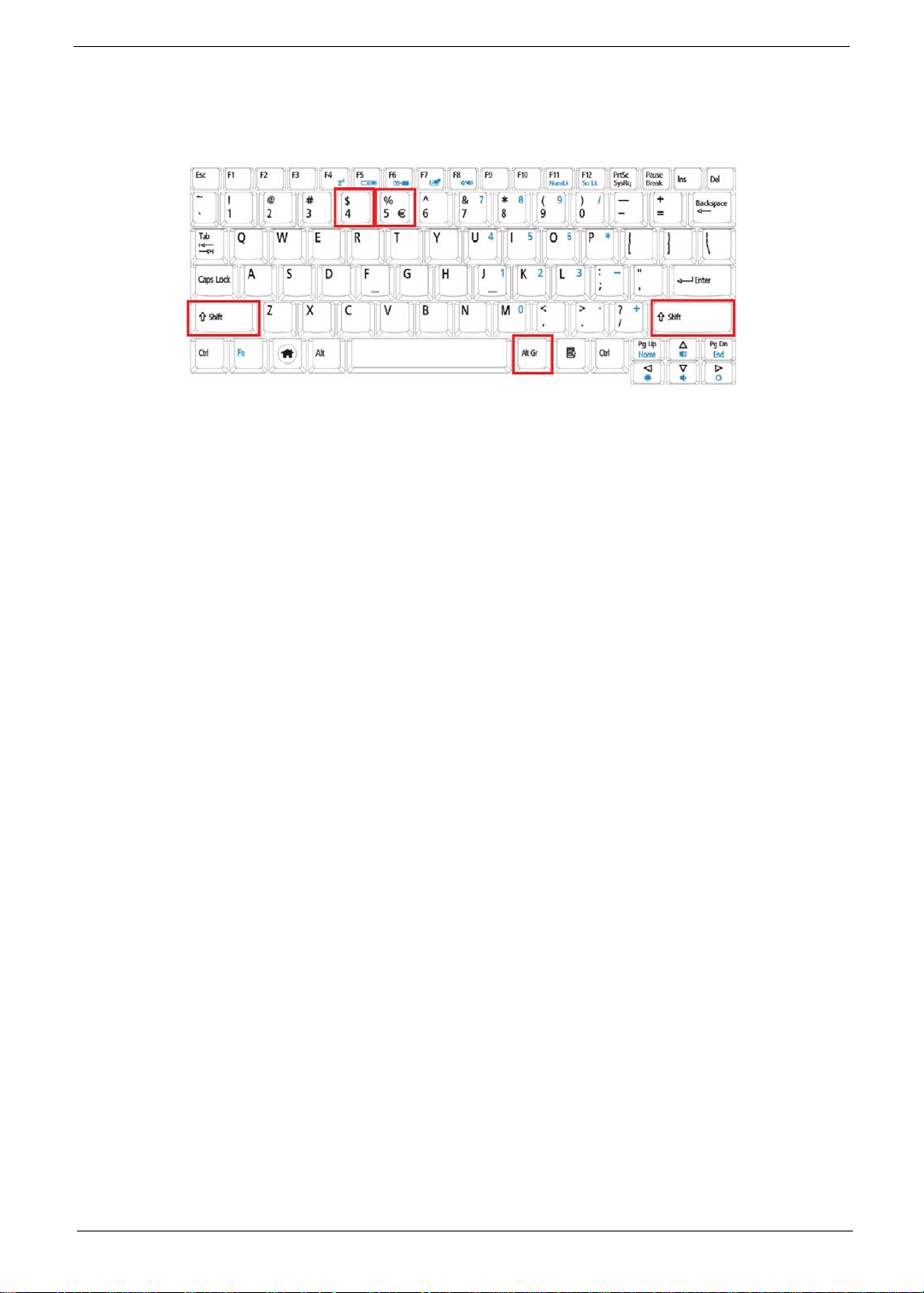
Special Key
You can locate the Euro symbol and the US dollar sign at the upper-center and/or bottom-right of your
keyboard.
The Euro symbol
1. Open a text editor or word processor.
2. Hold <Alt Gr> and then press the <5> key at the upper-center of the keyboard.
NOTE: Some fonts and software do not support the Euro symbol.
The US dollar sign
1. Open a text editor or word processor.
2. Hold <Shift> and then press the <4> key at the upper-center of the keyboard.
NOTE: This function varies according to the language settings.
Chapter 1 11
Page 22

Hardware Specifications and Configurations
Processor
Item Specification
CPU type Diamondville Atrom series standard voltage 533FSB processors
CPU package Diamondville 437-balls Micro-FCBGA8 package 22x22mm
Features
• New single-core processor for mobile devices with enhanced
performance
• On-die, primary 32-kB instructions cache and 24-kB write-back
data cache
• 100/133-MHz Source-Synchronous front side bus (FSB)
• Supports Hyper-Threading Technology 2-threads
• On-Die 512-kB, 8-way L2 cache
• Support for IA 32-bit and Intel® 64 architecture
• Streaming SIMD Extensions 2 and 3 (SSE2 and SSE3)
support
• Thermal management support via Intel Thermal Monitor 1 and
Intel Thermal Monitor 2
• FSB Lane Reversal for flexible routing
• Supports C0/C1(E)/C2(E)/C4(E)
• L2 Dynamic Cache Sizing
• Advanced power management features including Enhanced
Intel SpeedStep® Technology
• Execute Disable Bit support for enhanced security
System Controller
Item Specification
Processor Support
System Memory Support
Internal Graphics
DMI
• Intel Core 2 Duo mobile processor LV and ULV
• Intel Core Duo processor LV and ULV
• Intel Core Solo processor ULV
• Celeron M processor ULV
• 533-MHz and 667-MHz front side bus (FSB) support
• Supports single-channel DDR2 SDRAM only
• Maximum Memory supported 2 GB
• Memory Channel Topologies supported:-
• Single-channel with 1 SO-DIMM only (up to 1 GB)
• Single-channel with 1 SO-DIMM (up to 1 GB) and Memory
Down (up to 1 GB)
• Support for DDR2 at 400 MHz and 533 MHz
• 166-MHz core render clock and 200 MHz core display clock at
1.05-V core voltage only
• Support for only one SDVO port
• SDVO slot reversal not supported
• Support for dual-channel LVDS resolutions up to UXGA
• Support for CRT resolutions up to QXGA
• TV support for HDTV
• DMI lane width support for x2 only
• DMI Lane reversal not supported Package
12 Chapter 1
Page 23

Item Specification
Package
• FCBGA
• Ball Count: 998 balls
• Package Size: 27 mm x 27 mm
• Ball pitch: 0.8-mm uniform pitch
System Clock
Item Specification
System clock chip Built in
Package 56 pin TSSOP
Clock Synthesizer
• 100Mhz for CPU
• 100MHz clock buffer for PCI-E and ICH7M SATA
• 96MHz ICH7M
• 48Mhz for USB clock inside ICH7M
• 33Mhz PCI clock for PC device, LPC
• 14.31818Mhz for ICH7M and Audio
Power 3.3V
Features
• Support spread spectrum function, for reducing EMI
• Support SM bus interface
Crystal and Oscillator
Item Specification
Features
• 14.31818Mhz crystal for clock chip
• 32.768Khz crystal for ICH7M and WPCE775L
• 25MHZ crystal for LAN RTL8102EL
System Memory
Item Specification
Memory controller Built in
Memory size 512MB or 1GB DDR2 RAM (if 2Gb die support is available)
DIMM socket number 1
Supports memory size per socket 1GB
Supports maximum memory size 1GB
Supports DIMM type DDR II 533Mhz SDRAM memory interface design
Supports DIMM Speed 533Mhz SDRAM
System Storage
Item Specification
SSD
HDD
• USB or ZIF connector (PATA compatible) Interface
• 2GB, 4GB or 8GB
• USB connector BTO (not user selectable)
• 9.5mm height, 2.5" HDD
• Easily removable no more than two screws
• SATA bus
• 80GB/100GB/120GB/160GB and above
• 5400 and 7200 rpm (follow HDD roadmap)
• SATA connector BTO (not user selectable)
Chapter 1 13
Page 24

Hard Disk Drive Interface
Item Specification
Vendor &
Segate ST9120817AS Toshiba MK1252GSX WD WD1200BEVS WD WD1200BEVT
Model
Name
Capacity
120 120 120 120
(MB)
Bytes per
512 512 512 512
sector
Data
2222
heads
Drive Format
Disks 1 1 1 1
Spindle
5400 5400 5400 5400
speed
(RPM)
Performance Specifications
Buffer
8 MB 8 MB 8 MB 8 MB
size
Interface SATA SATA SATA SATA
Internal
transfer
778 400 ~ 794 typical 850 Mbits/s
maximum
850 Mbits/s
maximum
rate
(Mbits/
sec, max)
I/O data
300 300 150 maximum 300 maxi mu m
transfer
rate
(Mbytes/
sec max)
DC Power Requirements
Voltage
5V ±5% 5V ±5% 5V ±5% 5V ±5%
tolerance
Thermal Sensor Control
Item Specification
Thermal Sensor Chip G780
Package 8-pin MSOP
Features Thermal sensor control
Interface
2
C bus, address: 98h
I
BIOS
Item Specification
BIOS vendor InSyde
BIOS Version v0.2103
BIOS ROM type W25X80VSSIG
BIOS ROM size 1Mb CMOS Boot Block Flash Memory
BIOS package 8 pin SOIC
Block Size 64 Kb per block
14 Chapter 1
Page 25
Item Specification
Supply Current Active current =15 mA (Typical)
Standby current=4 µA (Typical)
LCD 8.9”
Item Specification
Vendor/model name AOU B089AW01 V1
Screen Diagonal (mm) 226.06
Active Area (mm) 195.07(H) X 113.4(V)
Display resolution (pixels) 1024x3(RGB) x 600
Pixel Pitch (mm) 0.1905 (H) x 0.189 (V)
Pixel Arrangement R.G.B. Vertical Stripe
Display Mode Normally White
2
180 typ. (center)
Typical White Luminance (cd/m
also called Brightness
)
150 min. (center)
Luminance Uniformity Max. (5 points)
Contrast Ratio 300 typ
Response Time (Optical Rise
30 typ / 50 max
Time/Fall Time) msec
Nominal Input Voltage VDD +3.3 typ.
Typical Power Consumption (watt) 3.0 max. (Include Logic and Black Light power)
Weight (without inverter) 190 max.
Physical Size (mm) Max: 213.66 (L) 129.85 (W) 5.45 (T)
Typical: 213.36 (L) 129.55 (W) 5.15 (T)
Electrical Interface 1 channel LVDS
Support Color 262K colors (RGB 6-bit)
Viewing Angle (degree)
Horizontal (Right) CR = 10 (Left)
Vertical (Upper) CR = 10 (Lower)
45, 45
15, 35
Temperature Range (°C)
Operating
Storage (shipping)
0 to +50
-20 to +65
RoHS Compliance RoHS Compliance
Chapter 1 15
Page 26
KBC
Item Specification
Chipset WPCE775L
Features
• Host interface, base on Intel's LPC Interface specification
Revision 1.0
• PC01 REV 0.3 and ACPI 1.0b compliant
• 16-bit RISC core, with 2 Mbyte address space, and
running at up to 20 MHZ
• Software and Hardware controlled clock throttling
• Share BIOS flash memory (internal and/or external)
• Y2K- compliant
• 84 GPIO ports with variety of wake-up events
• Extremely low current consumption in idle mode
• JTAG-base debugger interface
• 176 pin LQFP package
Audio Codec and Amplifier
Item Specification
Audio Controller Realtek ALC268 Azadia Codec and Amplifier G1441
Features
• HD Audio
• SNR > 85, High-performance DACs with 95dB SNR (A-
Weighting), ADCs with 85dB SNR (A-Weighting)
• Internal Digital Microphone
• Two speake rs, at least 1.0W for each
• 1* Analog Microphone, 1*Headphone jack
LAN Interface
Item Specification
LAN Chipset Realtek solution RTL8102EL
Features
• Support WOL from S53
• File deployment support
• LDCM support
Keyboard
Item Specification
Type New Acer flat keyboard
Total number of keypads 84
Windows logo key Yes
Internal & external keyboard work
Plug USB keyboard to the USB port directly: Yes
simultaneously
Mini Card
Item Specification
Number Supported 2
Features
• 2 mini card slot (1 for 3G and 1 for WLAN or WLAN/
WiMax)
• Embedded 3G module and built-in 1 antenna (combo-
wireless+3G) on top/side of LCD
16 Chapter 1
Page 27

Camera
Item Specification
Maximum Module Form Factor 65*8*4.74 mm3
Sensor Type and Resolution Color CMOS, VGA(640x480)
ISP USB 2.0 high speed
Focusing Type Fix Focus
F/N 2.8±5%
Focusing Range 30 cm ~infinity (theory) focus at 48 cm
Format of Image Output Data YUV
Frame Rate VGA: 30 fps (MAX.) @USB2.0 high speed
Operation Voltage Total Supply Voltage: 3.3V
ISP: 3.3, 1.8V
CMOS Sensor: 2.8V, 1.8V
System Interfacing USB 2.0 (High Speed)
Board Connector Type Wire to board 5-pin connector
PCB layer 4 layers
Power consumption Operation: Around 400mW @VGA 30fps
Suspend: < 500uA in Vista
Weight 1.8 g
3G Card
Item Specification
Type
Features
• 3G card in mini-PCI card size
• Control by USB interface
• User accessible SIM card by battery remove
• Antenna: Has to be placed on the sides of LCD in A/B
cover
Wireless LAN
Item Specification
Type Foxconn FOX_ATH_XB63 Foxconn Atheros XB63
Features
• Manufacturing option: mini-card
• 802.11b/g (3rd Party)
• Built-in 2 Antenna
• Antenna: Has to be placed on the top of LCD on the
sides of LCD latch
Battery
Item Specification
Vendor & model name Celexper UM-2008A, Panasonic
UM-2008A, Sanyo UM-2008A,
Panasonic UM-2008B, Sanyo
UM-2008B
Simplo UM-2008A
Battery Type Li-Ion 3S1P Li-Ion 3S2P
Pack capacity 4400mAh 5200mAh
Number of battery cell 3 6
Package configuration 3S1P 3S2P
Chapter 1 17
Page 28

18 Chapter 1
Page 29

Chapter 2
System Utilities
BIOS Setup Utility
The BIOS Setup Utility is a hardware configuration program built into your computer’s BIOS (Basic Input/
Output System).
Y our computer is already properly configured and optimized, and you do not need to run this utility . However, if
you encounter configuration problems, you may need to run Setup. Please also refer to Chapter 4
Troubleshooting when problem arises.
To activate the BIOS Utility, press F2 during POST (when “Press <F2> to enter Setup” message is prompted
on the bottom of screen).
Press F2 to enter setup. The default parameter of F12 Boot Menu is set to “disabled”. If you want to change
boot device without entering BIOS Setup Utility, please set the parameter to “enabled”.
Press <F12> during POST to enter multi-boot menu. In this menu, user can change boot device without
entering BIOS SETUP Utility.
Navigating the BIOS Utility
There are six menu options: Information, Main, Advanced, Security, Boot, and Exit.
Follow these instructions:
• To choose a menu, use the left and right arrow keys.
• To choose an item, use the up and down arrow keys.
• To change the value of a parameter, press F5 or F6.
• A plus sign (+) indicates the item has sub-items. Press Enter to expand this item.
• Press Esc while you are in any of the menu options to go to the Exit menu.
• In any menu, you can load default settings by pressing F9. You can also press F10 to save any
changes made and exit the BIOS Setup Utility.
NOTE: You can change the value of a parameter if it is enclosed in square brackets. Navigation keys for a
particular menu are shown on the bottom of the screen. Help for parameters are found in the Item
Specific Help part of the screen. Read this carefully when making changes to parameter values. Please
note that system information is subject to different models.
Chapter 2 19
Page 30

Information
The Information screen displays a summary of your computer hardware information.
InsydeH20 Setup Utility Rev. 3.5
Inform a tion Main Security Boot Exit
CPU Type: Genuine Intel (R) CPU N27 0
CPU Speed: 1.60GHz
HDD Mod el Na me: INTEL Ca stle Point
HDD Se r ial Number :
System BIOS Version: v0.2103
VGA BIOS Version: Intel V1585
Seri al Number: ZG008160067
Ass et Tag Number:
Product Name:
Manufacturer Name: Acer
UUID: 405FE2E9A4E1D4118251001E684CE894
00008030320000000000
F1 Help ↑↓ Select Item F5/F6 Change Values F9 S etup Default
ESC Exit ←→ Select Menu Enter SelectXSubMenu F10 Save and Ex it
NOTE: The system information is subject to different models.
Parameter Description
CPU Type This field shows the CPU type and speed of the system.
CPU Speed This field shows the speed of the CPU.
HDD Model Name This field shows the model name of HDD installed on primary IDE master.
HDD Serial Number This field displays the serial number of HDD installed on primary IDE master.
System BIOS Version Displays system BIOS version.
VGA BIOS Version This field displays the VGA firmware version of the system.
Serial Number This field displays the serial number of this unit.
Asset Tag Number This field displays the asset tag number of the system.
Product Name This field shows product name of the system.
Manufacturer Name This field displays the manufacturer of this system.
UUID Number Universally Unique Identifier (UUID) is an identifier standard used in software
construction, standardized by the Open Software Foundation (OSF) as part of
the Distributed Computing Environment (DCE).
20 Chapter 2
Page 31

Main
The Main screen allows the user to set the system time and date as well as enable and disable boot option
and recovery.
InsydeH20 Setup Utility Rev. 3.5
Informati on Main Security Boot Exit
Item Specific Help
Sy st em Time [13: 04: 04] This is t he help for the
Sy st em Dat e [06/ 04/ 2008] hour field. V ali d range
is from 0 to 23.
Total Mem ory 512 M B INCREASE/REDUCE : F5/F6
Video M em ory [ 8 M B ]
Quic k B oot [Enabled]
Network B oot [Enabl ed]
F12 B oot M enu [ E nabl ed]
D2D Recovery [Enabled]
F1 Help ↑↓ Select Item F5/F6 Change Values F9 Set up Default
ESC Exit
NOTE: The screen above is for your reference only. Actual values may differ.
The table below describes the parameters in this screen. Settings in boldface are the default and suggested
parameter settings.
Parameter Description Format/Option
System Time Sets the system time. The hours are displayed with 24-
System Date Sets the system date. Format MM/DD/YYYY
Total Memory This field reports the memory size of the system.
Video Memory
Quick Boot Allows startup to skip certain tests while booting,
Network Boot Enables, disables the system boot from LAN (remote
F12 Boot Menu Enables, disables Boot Menu during POST. Option: Enabled or Enabled
D2D Recovery Enables, disables D2D Recovery function. The function
Select Menu Enter SelectXSubMenu F10 Save and Ex it
←→
Format: HH:MM:SS
hour format.
Memory size is fixed to 3017 MB.
Shows the video memory size. VGA Memory size=32 MB
decreasing the time needed to boot the system.
server).
allows the user to create a hidden partition on hard disc
drive to store operation system and restore the system
to factory defaults.
(hour:minute:second)
(month/day/year)
N/A
N/A
Option: Enabled or Disabled
Option: Enabled or Disabled
Option: Enabled or Disabled
Chapter 2 21
Page 32

Security
The Security screen contains parameters that help safeguard and protect your computer from unauthorized
use.
InsydeH20 S et up Ut ili t y Rev. 3.5
Informati on Main Security Boot Exit
Item S pec i fic Help
Supervis or P as sword Is: Clear Inst all or Change t he
User P assword Is: Clear pass word and t he l engt h
than eight words .
Set S upervi s or Pas s word
Set User Password
Power on pas sword [E nabl ed]
F1 Help ↑↓ Select Item F5/F6 Change Values F9 Set up Default
ESC Exit
The table below describes the parameters in this screen. Settings in boldface are the default and suggested
parameter settings.
Parameter Description Option
Supervisor Password Is Shows the setting of the Supervisor password Clear or Set
User Password Is Shows the setting of the user password. Clear or Set
Set Supervisor Password Press Ente r to set the supervisor password. When
Set User Password Press Enter to set the user password. When user
Power on password Defines whether a password is required or not while
NOTE: When you are prompted to enter a password, you have three tries before the system halts. Don’t forget
your password. If you forget your password, you may have to return your notebook computer to your
dealer to reset it.
Select Menu Enter SelectXSubMenu F10 Save and Ex i t
←→
set, this password protects the BIOS Setup Utility
from unauthorized access. The user can not either
enter the Setup menu nor change the value of
parameters.
password is set, this password protects the BIOS
Setup Utility from unauthorized access. The user can
enter Setup menu only and does not have right to
change the value of parameters.
the events defined in this group happened. The
following sub-options are all requires the Supervisor
password for changes and should be grayed out if the
user password was used to enter set u p.
Enabled or
Disabled
22 Chapter 2
Page 33

Setting a Password
Follow these steps as you set the user or the supervisor password:
1. Use the ↑ and ↓ keys to highlight the Set Supervisor Password parameter and press the Enter key. The
Set Supervisor Password box appears:
2. Type a password in the “Enter New Password” field. The password length can not exceeds 8
alphanumeric characters (A-Z, a-z, 0-9, not case sensitive). Retype the password in the “Confirm New
Password” field.
IMPORTANT:Be very careful when typing your password because the characters do not appear on the screen.
3. Press Enter. After setting the password, the computer sets the User Password parameter to “Set”.
4. If desired, you can opt to enable the Password on boot parameter.
5. When you are done, press F10 to save the changes and exit the BIOS Setup Utility.
Removing a Password
Follow these steps:
1. Use the ↑ and ↓ keys to highlight the Set Supervisor Password parameter and press the Enter key. The
Set Password box appears:
2. Type the current password in the Enter Current Passwor d fi el d an d press Enter.
3. Press Enter twice without typing anything in the Enter New Password and Confirm New Password fields.
The computer then sets the Supervisor Password parameter to “Clear”.
4. When you have changed the settings, press u to save the changes and exit the BIOS Setup Utility.
Chapter 2 23
Page 34

Changing a Password
1. Use the ↑ and ↓ keys to highlight the Set Supervisor Password parameter and press the Enter key. The
Set Password box appears.
2. Type the current password in the Enter Current Passwor d fi el d an d press Enter.
3. Type a password in the Enter New Password field. Retype the password in the Confirm New Password
field.
4. Press Enter. After setting the password, the computer sets the User Password parameter to “Set”.
5. If desired, you can enable the Password on boot parameter.
6. When you are done, press F10 to save the changes and exit the BIOS Setup Utility.
If the verification is OK, the screen will display as following.
The password setting is complete after the user presses Enter.
If the current password entered does not match the actual current password, the screen will show you the
Setup Warning.
If the new password and confirm new password strings do not match, the screen will display the following
message.
24 Chapter 2
Page 35

Boot
This menu allows the user to decide the order of boot devices to load the operating system. Bootable devices
includes the USB diskette drives, the onboard hard disk drive and the DVD drive in the module bay.
Insy deH20 S et up Ut il it y Rev. 3.5
Informati on Main Sec urity Boot Exit
Item S pec i fic Help
Boot priorit y order: Use <↑> or <↓> to select
a device, then pres s
1. ID E0 : IN TEL Ca stle Poi n t <F 5> t o m ove it down t he
2. IDE1 : list, or <F6> to move
3. US B F DD : it up t he list . P res s
4. US B HDD : <E sc > t o es cape t he m enu
5. Net work B oot : LE G A CY P CI DEV ICE
6. USB CDRO M :
F1 Help ↑↓ Select Item F5/F6 Change Values F9 Set up Default
ESC Exit
Select Menu Enter SelectXSubMenu F10 Save and Exit
←→
Chapter 2 25
Page 36

Exit
The Exit screen allows you to save or discard any changes you made and quit the BIOS Utility.
Insy deH20 S et up Ut ilit y Rev. 3.5
Information Main Sec urit y B oot Exit
Item S pec ific Help
Exit S aving Changes Ex it S y st em S et up and
Exit Dis carding Changes save your changes t o
Load Set up Defaults CMOS.
Discard Changes
Save Changes
F1 Help ↑↓ Select Item F5/F6 Change Values F9 Setup Default
ESC Exit
The table below describes the parameters in this screen.
Parameter Description
Exit Saving Changes Exit System Setup and save your changes to CMOS.
Exit Discarding
Changes
Load Setup Default Load default values for all SETUP item.
Discard Changes Load previous values from CMOS for all SETUP items.
Save Changes Save Setup Data to CMOS.
Select M enu Enter SelectXSubMenu F10 Save and Exit
←→
Exit utility without saving setup data to CMOS.
26 Chapter 2
Page 37

BIOS Flash Utility
The BIOS flash memory update is required for the following conditions:
• New versions of system programs
• New features or options
• Restore a BIOS when it becomes corrupted.
Use the Phlash utility to update the system BIOS flash ROM.
NOTE: Create a Crisis Recovery Media (such as USB HDD) before you use the Phlash utility.
NOTE: Do not install memory-related drivers (XMS, EMS, DPMI) when you use the Phlash.
NOTE: Please use the AC adaptor power supply when you run the Phlash utility. If the battery pack does not
contain enough power to finish BIOS flash, the system will not boot as the BIOS is not loaded.
Perform the following steps to use the Flash Utility:
1. Press F2 during boot to enter the Setup Menu.
2. Select Boot Menu to modify the boot priority order, for example, if using USB HDD to Update BIOS, move
USB HDD to position 1.
3. Execute the IFLASH.BAT batch file to update BIOS (Read xxxxx.fd to Memory).
Chapter 2 27
Page 38

4. In flash BIOS, the message Please do not remove AC Power Source displays.
NOTE: If the AC power is not connected, the following message displays.
Plug in the AC power to continue.
5. Flash is complete when the following message displays.
6. Shutdown or reboot base on iflash.bat command.
28 Chapter 2
Page 39

Remove HDD/BIOS Utility
This section provide you with removing HDD/BIOS method:
Remove HDD Password:
• If you key in wrong HDD password three times, Hdd password error code displays. See the image
below.
To reset the HDD password, run HDD_PW.EXE as follows:
1.
Key in hdd_pw 15494 0
2. Press 2.
3. Select one upper-case string from the list.
4. Reboot system and key in the selected string (0KJFN42 or UVEIQ96) on the HDD User
Password screen.
Chapter 2 29
Page 40

Remove BIOS Password:
If you key in the wrong Supervisor Password three times, System Disabled displays on the screen. See the
image below.
To reset the BIOS password, run BIOS_PW.EXE as follows:
1.
Key in bios_pw 14452 0
2. Select one string from the list.
30 Chapter 2
Page 41

3. Reboot the system and key in the selected string (qjjg9vy, 07yqmjd etc.) for the BIOS user
password.
Chapter 2 31
Page 42

32 Chapter 2
Page 43

Machine Disassembly and Replacement
This chapter contains step-by-step procedures on how to disassemble the notebook computer for
maintenance and troubleshooting.
Disassembly Requirements
To disassemble the computer, you need the following tools:
• Wrist grounding strap and conductive mat for preventing electrostatic discharge
• Flat screwdriver
• Philips screwdriver
• Plastic flat screwdriver
• Plastic tweezers
NOTE: The screws for the different components vary in size. During the disassembly process, group the
screws with the corresponding components to avoid mismatch when putting back the components.
Related Information
Please note that the images were taken using the HDD SKU, unless otherwise specified, and may differ
slightly from a SSD SKU.
The product previews seen in the disassembly procedures may not represent the final product color.
Chapter 3
Chapter 3 33
Page 44

General Information
Pre-disassembly Instructions
Before proceeding with the disassembly procedure, make sure that you do the following:
1. Turn off the power to the system and all peripherals.
2. Unplug the AC adapter and all power and signal cables from the system.
3. Place the system on a flat, stable surface.
4. Remove the battery pack.
Disassembly Process
The disassembly process is divided into the following sections:
• Upper cover disassembly
• LCD module disassembly
• Main unit disassembly
The flowcharts provided in the succeeding disassembly sections illustrate the entire disassembly sequence.
Observe the order of the sequence to avoid damage to any of the hardware components. For example, if you
want to remove the main board, you must first remove the keyboard, then disassemble the inside assembly
frame in that order.
Main Screw List
Screw Quantity Part Number
M2*3 (NL) 25 86.S0207.001
M2.5*4 (NL) 2 86.D01V7.001
M2*4-NI (NL) 5 86.W0107.003
M2*5 (NL) 20 86.TG607.004
M3*3.5 4 86.TDY07.003
34 Chapter 3
Page 45

External Module Disassembly Process
External Modules Disassembly Flowchart
The flowchart below gives you a graphic representation on the entire disassembly sequence and instructs you
on the components that need to be removed during servicing. Disassembly is divided into two tiers. Tier 1
comprises of FRU parts that do not require complete disassembly of the computer. Tier 2 incorporates the
remaining FRU parts that require complete disassembly.
Screw List
Step Screw Quantity Color Part No.
Upper Cover
M2*5 5 Black 86.TG607.004
M2*3 (NL) 3 Black 86.S02 07.001
Chapter 3 35
Page 46

Removing the Battery Pack
1. Turn computer over.
2. Slide the battery lock/unlock latch to the unlock position.
3. Slide and hold the battery release latch to the release position (1), then slide out the battery pack from the main
unit (2).
1
2
36 Chapter 3
Page 47

Removing the 3G Cover
1. Remove the Battery Pack. See “Removing the Battery Pack” on page 36.
2. Loosen the ten captive screws from the Memory, HDD1, and HDD2 Covers.
3. Remove the two captive screws.
4. Lift the 3G cover up to remove.
Chapter 3 37
Page 48

Removing the Keyboard
1. Turn the computer rightside up and unlock the three (3) securing latches.
2. Grasp the keyboard and lift up to remove.
3. Lift the keyboard over and disconnect the keyboard FFC.
4. Remove the keyboard and place it on a clean surface.
38 Chapter 3
Page 49

Removing the Upper and Lower Covers
1. Remove the Battery Pack. See “Removing the Battery Pack” on page 36.
2. Turn the computer upside down. Remove the three securing screws under the battery pack.
3. Remove the two rubber foot pads and the eight securing screws.
Step Size Quantity Screw Type
Upper Cover M2*3 (NL)
Red callout
3
Upper Cover M2*5 (NL)
Green callout
4. Turn the computer rightside up and disconnect the TouchPad FFC.
5
Chapter 3 39
Page 50

5. Remove the five (5) securing screws.
Step Size Quantity Screw Type
Upper Cover M2*5 (NL) 5
6. Grasp the bottom of the upper cover and pry apart.
7. Lift the upper cover to remove completely.
40 Chapter 3
Page 51

LCD Module Disassembly Process
LCD Module Disassembly Flowchart
Screw List
Step Screw Quantity Color Part No.
LCD Bezel M2*5 (NL) 6 Black 86.TG607.004
LCD Module M2*5 (NL) 4 Black 86.TG607.004
LCD Panel M2*4 (NL) 5 Black 86.W0107.003
LCD Brackets M2*3 (NL) 4 Black 86.TG607.004
Chapter 3 41
Page 52

Removing the LCD Module
1. Remove the Upper Cover. See “Removing the Upper and Lower Covers” on page 39.
2. Disconnect the LCD cable from its connector
3. Disconnect and remove the antenna cables from the housing well.
NOTE: Main cable is black. The Auxiliary cable is white.
42 Chapter 3
Page 53

4. Remove the four securing screws from the hinges.
Step Size Quantity Screw Type
LCD Module M2*5 (NL) 4
5. Tilt the LCD module so it sits at a 90 degree angle.
IMPORTANT:Ensure all cables are clear of the lower cover before removing the LCD module.
6. Grasp the module by both sides and lift upwards.
Chapter 3 43
Page 54

Removing the LCD Bezel
1. Remove the LCD Module. See “Removing the LCD Module” on page 42.
2. Remove the four round and the two semi-rectangular screw caps.
3. Remove the six (6) securing screws.
Step Size Quantity Screw Type
LCD Bezel M2*5 (NL) 6
4. Starting from the inside edges, pry the inside of the bezel upwards from the panel. Continue moving left until
the bezel is removed. If necessary, use a plastic pry to release the corners of the bezel.
5. Lift up the bezel and remove it from the LCD Module.
44 Chapter 3
Page 55

Removing the Camera Board
1. Remove the LCD Bezel. See “Removing the LCD Bezel” on page 44.
2. Disconnect the Camera Module cable from its connector as shown.
3. Remove the camera board from the LCD cover.
Chapter 3 45
Page 56

Removing the MIC Board
1. Remove the LCD Bezel. See “Removing the LCD Bezel” on page 44.
2. Disconnect the MIC cable from its connector as shown.
3. Remove the MIC board from the LCD cover.
46 Chapter 3
Page 57

Removing the LCD Panel
1. Remove the LCD Bezel. See “Removing the LCD Bezel” on page 44.
2. Disconnect the MIC cable. See “Removing the MIC Board” on page 46.
3. Remove the five (5) securing screws from the LCD Module.
Step Size Quantity Screw Type
LCD Panel M2*4 (NL) 5
4. Grasp the left hinge and pivot down before pulling up.
5. Remove it from its housing well.
Chapter 3 47
Page 58

6. Hold the LCD Panel from the sides and lift to remove. Place it on a clean surface.
Removing the LCD Brackets and FPC Cable
1. Remove the LCD Panel. See “Removing the LCD Panel” on page 47.
2. Turn the LCD panel over on a clean surface. Remove the adhesive strips securing the LCD cable.
3. Disconnect the LCD cable from its connector as shown.
48 Chapter 3
Page 59

4. Remove the four securing screws (two each side) from the LCD Panel brackets.
Step Size Quantity Screw Type
LCD Brackets M2*3 NL 4
NOTE: The brackets are paired diagonally and marked as shown below.
Chapter 3 49
Page 60

Main Unit Disassembly Process
Main Unit Disassembly Flowchart
Screw List
Step Screw Quantity Color Part No.
WLAN M2*3 (NL) 1 Black 86.S0207.001
USB/LED/Power
Board (HDD SKU)
USB/LED/Power
Board (SSD SKU)
SSD Module M2*3 2 Black 86.S0207.001
Mainboard M2*3 1 Black 86.S0207.001
Speaker Module M2*3 4 Black 86.S0207.001
HDD Module M2.5*4 2 Black 86.D01V7.001
HDD Carrier M3*3.5 4 Black 86.TDY07.003
Thermal Module M2*3 3 Black 86.S0207.001
M2*3 (NL) 3 Black 86.S0207.001
M2*3 (NL) 4 Black 86.S0207.001
50 Chapter 3
Page 61

Removing the WLAN Module
1. See “Removing the Battery Pack” on page 36.
2. Remove the securing screw as shown.
Step Size Quantity Screw Type
WLAN Module M2*3 (NL) 1
NOTE: The antenna cables were removed during the LCD module disassembly. See “Removing the LCD
Module” on page 42.
3. The module pops up. Remove it from the mainboard as shown.
Chapter 3 51
Page 62

Removing the USB/LED/Power/Card Reader Board
1. Remove the upper cover. See “Removing the Upper and Lower Covers” on page 39.
2. Remove the three (3) securing screws as shown.
HDD SKU
Step Size Quantity Screw Type
HDD SKU:
USB/LED/Power
board
SDD SKU:
USB/LED/Power
board
3. Lift the board to expose the USB/LED/Power board to mainboard cable.
M2*3 (NL) 3
M2*3 (NL) 4
SSD SKU
52 Chapter 3
Page 63

4. Disconnect the cable and remove the board.
Removing the SSD Module
IMPORTANT:The SSD module is only available on the Aspire one SSD SKU.
1. Remove the mainboard. See “Removing the Mainboard” on page 55.
2. Disconnect the FFC from its connector.
3. Disconnect the FFC cable from the module.
NOTE: To prevent damage to device, avoid pressing down on it or placing heavy objects on top of it.
Chapter 3 53
Page 64

4. Remove the two securing screws.
Step Size Quantity Screw Type
SSD Module M2*3 (NL) 2
5. Remove the SSD module.
54 Chapter 3
Page 65

Removing the Mainboard
1. Remove the Upper Cover. See “Removing the Upper and Lower Covers” on page 39.
2. Remove the WLAN module. See “Removing the WLAN Module” on page 51.
3. Remove the USB/LED/Power/Card Reader Board. See “Removing the USB/LED/Power/Card Reader Board”
on page 52.
4. Disconnect the speaker to mainboard cable.
5. Remove the single securing screw.
Step Size Quantity Screw Type
Mainboard M2*3 (NL) 1
Chapter 3 55
Page 66

6. Grip the mainboard and remove.
NOTE: The SSD image may differ from the following illustration.
Removing the Speaker Module
1. Remove the Upper Cover. See “Removing the Upper and Lower Covers” on page 39.
2. Peel back the two adhesive strips.
56 Chapter 3
Page 67

3. Remove the four (4) securing screws (2 on each side).
Step Size Quantity Screw Type
Speaker Module M2*3 (NL) 4
4. Remove the Speaker Module from the upper cover.
Chapter 3 57
Page 68

Removing the Hard Disk Drive Module
IMPORTANT:The HDD is only available on the Aspire one HDD SKU.
1. Remove the mainboard. See “Removing the Mainboard” on page 55.
2. Remove the two securing screws to release the carrier.
Step Size Quantity Screw Type
HDD Module M2.5*4 (NL) 2
3. Hold the carrier and slide the HDD away from the mainboard.
NOTE: To prevent damage to device, avoid pressing down on it or placing heavy objects on top of it.
58 Chapter 3
Page 69

4. Remove the four screws (two each side) securing the HDD to the carrier.
Step Size Quantity Screw Type
HDD Carrier M3*3.5 (NL) 4
5. Turn the HDD on its side and pull the carrier away.
Chapter 3 59
Page 70

Removing the DIMM Module
IMPORTANT:The Aspire one SSD SKU does not come standard with DIMM modules. The modules are
optional components for this SKU.
1. Remove the mainboard. See “Removing the Mainboard” on page 55.
2. Push out the release latches on both sides of the DIMM socket to release the DIMM module.
3. Remove the DIMM module.
60 Chapter 3
Page 71

Removing the Thermal Module
1. Remove the Mainboard. See “Removing the Mainboard” on page 55.
2. Turn the Mainboard CPU side up, and place it on a clean surface.
3. Grip the cable connector and disconnect the Fan cable from the mainboard.
IMPORTANT:Do not grip the cable itself to prevent stripping.
4. Remove the three securing screws from the heatsink.
Step Size Quantity Screw Type
Thermal Module M2*3(NL) 3
Chapter 3 61
Page 72

5. Remove the thermal module.
62 Chapter 3
Page 73

LCD Module Reassembly Procedure
Replacing the LCD Brackets and FPC Cable
1. Replace the four LCD brackets as shown.
IMPORTANT:The indicator pairs on the brackets must be located diagonally opposite each other.
2. Turn the LCD panel over and connect the FPC cable to the panel.
3. Secure the cable with the adhesive strips as shown.
Chapter 3 63
Page 74

Replacing the LCD Panel
IMPORTANT:Before installing, take care of the following items:
• All cabling must be tucked tightly and close to the panel
• Check that the cables are tucked under the hinge brackets and run on the outside of the hinges
1. Place the LCD Panel in to the case as shown. 2. Replace the left hinge as shown.
3. Replace the five securing screws as shown.
64 Chapter 3
Page 75

Replacing the Mic Board
1. Replace the Mic board in to the case. 2. Connect the MIC cable as shown.
Replacing the Camera Board
1. Replace the camera board in to the case. 2. Connect the camera cable as shown.
Chapter 3 65
Page 76

Replacing the LCD Bezel
1. Starting from the bottom, locate the bezel correctly and press down the edges until there are no gaps
between the bezel and the LCD Module.
2. Replace the six screws and the rubber screw caps provided.
66 Chapter 3
Page 77

Main Module Reassembly Procedure
Replacing the Thermal Module
1. Replace the Fan module on the Mainboard. 2. Replace the three screws in the order shown,
starting with number 1.
3. Connect the Fan cable to the Mainboard.
Replacing the DIMM Module
IMPORTANT:The Aspire one SSD SKU does not come standard with DIMM modules. The modules are
optional components.
1. Insert DIMM1 in to the socket. 2. Press down to locate DIMM correctly.
Chapter 3 67
Page 78

Replacing the Hard Disk Drive Module
IMPORTANT:The HDD is only available on the Aspire one HDD computer SKU.
1. Place the HDD in the HDD carrier. 2. Replace the four screws (two each side) to secure
the carrier.
3. Hold the carrier and slide the HDD toward the
mainboard until the interface connects.
4. Replace the two securing screws.
Replacing the Speaker Module
1. Replace the Speaker Module in the lower cover. 2. Replace the four securing screws.
68 Chapter 3
Page 79

3. Replace the two adhesive strips.
Chapter 3 69
Page 80

Replacing the Mainboard
IMPORTANT:Before replacing the motherboard, take care of the following items:
• Check that LED isn’t broken (top of mainboard)
• Check that the mylar next to the CPU module isn’t damaged (bottom of mainboard)
• Check the thermal power supply cable is connected properly
1. Insert the mainboard left side first into the lower
cover.
3. Connect the speaker cable to the mainboard.
2. Replace the securing screw on the Mainboard.
70 Chapter 3
Page 81

Replacing the SDD Module
IMPORTANT:The SSD module is only available on the Aspire one SSD computer SKU.
1. Place the SDD in the lower case. 2. Replace the two screws to secure the module.
3. Connect the FFC cable to the module and close
the cable latch.
4. Connect the FFC cable to the mainboard and close
the cable latch.
Chapter 3 71
Page 82

Replacing the USB/LED/Power/Card Reader Board
IMPORTANT:Before installing the USB board, take care of the following items:
• Check that LED isn`t broken
• SLIDER work smoothly
1. Connect the cable to the board. 2. Turn the board over and place it in the lower case.
3. Replace the three or four screws (depending on SKU) to secure the module.
HDD SKU
4. Connect the FFC cable to the module and close
the cable latch.
72 Chapter 3
5. Connect the FFC cable to the mainboard and close
the cable latch.
SSD SKU
Page 83

Replacing the WLAN Board
1. Insert the WLAN board in to the socket. 2. Push the board down and replace the securing
screw.
Replacing the LCM Module
1. Place the LCM module on to the lower cover at a 90 degree angle.
IMPORTANT:Ensure all cables are clear of the hinges before replacing the LCM module.
2. Replace the four screws (two each side) to secure the LCM module to the lower cover.
Chapter 3 73
Page 84

3. Replace the antenna cables in the housing well, as shown .
4. Replace the two antenna cables.
NOTE: The following is the correct cable-color to
connector designation: Black to MAIN (left)
and White to AUX (right).
5. Connect the LCD cable to the mainboard.
74 Chapter 3
Page 85

Replacing the Upper Cover
IMPORTANT:While replacing the upper cover, take note of the following items:
• Check that the mainboard is tucked underneath the housing wells in the lower cover
• Check that the speaker cable is attached
• Check that the antenna cables are tucked inside the housing well and do not interfere with the card reader
• Antenna cables must be secured to the chassis walls with the provided gasket tape
• Antenna cable on the right side must pass through the right side of hinge block
• Make sure that the 40-PIN Cable doesn`t interfere with the speaker module
1. Place the upper cover over the lower base, hinge
side first.
2. Set the Upper Cover down on the lower base and
press down as shown.
3. Replace the five securing screws on the Upper
Cover.
4. Reconnect the touchpad FCC cable and close the
cable latch.
Chapter 3 75
Page 86

5. Turn the computer upside down and replace the eight securing screws on the bottom panel to attach the
upper and lower covers.
6. Replace the two rubber foot pads.
Replacing the Keyboard
1. Replace keyboard cable to the mainboard, and
secure the locking latch.
3. Press down on the areas shown below to secure in place.
2. Turn the keyboard over and place the front edge
first in the mounting.
76 Chapter 3
Page 87

Replacing the 3G cover
1. Replace the 3G cover. 2. Secure the two captive screws.
Replacing the Battery
1. Slide and hold the battery release latch (1), insert
battery in to the main unit (2).
1
2
2. Slide the battery lock/unlock latch to the lock
position.
Chapter 3 77
Page 88

78 Chapter 3
Page 89

Troubleshooting
Common Problems
Use the following procedure as a guide for computer problems.
NOTE: The diagnostic tests are intended to test only Acer products. Non-Acer products, prototype cards, or
modified options can give false errors and invalid system responses.
1. Obtain the failing symptoms in as much detail as possible.
2. Verify the symptoms by attempting to re-create the failure by running the diagnostic test or by repeating
the same operation.
3. Use the following table with the verified symptom to determine which page to go to.
Symptoms (Verified) Go To
Power On Issue Page 80
No Display Issue Page 81
LCD Failure Page 84
Internal Keyboard Failure Page 84
TouchPad Failure Page 85
Internal Speaker Failure Page 85
Internal Microphone Failure Page 87
Rightside USB Failure Page 89
Power Button Failure Page 89
Other Functions Failure Page 90
Intermittent Failures Page 91
Undermined Failures Page 91
Chapter 4
4. If the Issue is still not resolved, see “Online Support Information” on page 161.
Chapter 4 79
Page 90

Power On Issue
If the system doesn’t power on, perform the following actions one at a time to correct the problem. Do not
replace a non-defective FRUs:
Computer Shutsdown Intermittently
If the system powers off at intervals, perform the following actions one at a time to correct the problem.
1. Check the power cable is properly connected to the computer and the electrical outlet.
2. Remove any extension cables between the computer and the outlet.
3. Remove any surge protectors between the computer and the electrical outlet. Plug the computer directly
into a known good electrical outlet.
4. Remove all external and non-essential hardware connected to the computer that are not necessary to
boot the computer to the failure point.
5. Remove any recently installed software.
6. If the Issue is still not resolved, see “Online Support Information” on page 161.
80 Chapter 4
Page 91

No Display Issue
If the Display doesn’t work, perform the following actions one at a time to correct the problem. Do not replace
a non-defective FRUs:
Chapter 4 81
Page 92

No POST or Video
If the POST or video doesn’t display, perform the following actions one at a time to correct the problem.
1. Make sure that the internal display is selected. On this notebook model, switching between the internal
display and the external display is done by pressing Fn+F5. Reference Product pages for specific model
procedures.
2. Make sure the computer has power by checking at least one of the following occurs:
• Fans start up
• Status LEDs light up
If there is no power, see “Power On Issue” on page 80.
3. Drain any stored power by removing the power cable and battery and holdin g down the power button for
10 seconds. Reconnect the power and reboot the computer.
4. Connect an external monitor to the computer and switch between the internal display and the external
display is by pressing Fn+F5 (on this model).
If the POST or video appears on the external display, see “LCD Failure” on page 84.
5. Disconnect power and all external devices including port replicators or docking stations. Remove any
memory cards and CD/DVD discs. Restart the computer.
If the computer boots correctly, add the devices one by one until the failure point is discovered.
6. Reseat the memory modules.
7. Remove the drives (see “Disassembly Process” on page 34).
8. If the Issue is still not resolved, see “Online Support Information” on page 161.
82 Chapter 4
Page 93

Abnormal Video Display
If video displays abnormally, perform the following actions one at a time to correct the problem.
1. Reboot the computer.
2. If permanent vertical/horizontal lines or dark spots display in the same location, the LCD is faulty and
should be replaced. See “Disassembly Process” on page 34.
3. If extensive pixel damage is present (different colored spots in the same locations on the screen), the LCD
is faulty and should be replaced. See “Disassembly Process” on page 34.
4. Adjust the brightness to its highest level. See the User Manual for instructions on adjusting settings.
NOTE: Ensure that the computer is not running on battery alone as this may reduce display brightness.
If the display is too dim at the highest brightness setting, the LCD is faulty and should be replaced. See
“Disassembly Process” on page 34.
5. Check the display resolution is correctly configured:
a. Minimize or close all Windows.
b. If display size is only abnormal in an application, check the view settings and control/mouse wheel
zoom feature in the application.
c. If desktop display resolution is not normal, right-click on the desktop and select
Personalize´ Display Settings.
d. Click and drag the Resolution slider to the desired resolution.
e. Click Apply and check the display. Readjust if necessary.
6. Roll back the video driver to the previous version if updated.
7. Remove and reinstall the video driver.
8. Check the Device Manager to determine that:
• The device is properly installed. There are no red Xs or yellow exclamation marks.
• There are no device conflicts.
• No hardware is listed under Other Devices.
9. If the Issue is still not resolved, see “Online Support Information” on page 161.
10. Run the Windows Memory Diagnostic from the operating system DVD and follow the onscreen prompts.
11. If the Issue is still not resolved, see “Online Support Information” on page 161.
Random Loss of BIOS Settings
If the computer is experiencing intermittent loss of BIOS information, perform the following actions one at a
time to correct the problem.
1. If the computer is more than one year old, replace the CMOS battery.
2. Run a complete virus scan using up-to-date software to ensure the computer is virus free.
3. If the computer is experiencing HDD or ODD BIOS information loss, disconnect and reconnect the power
and data cables between devices.
If the BIOS settings are still lost, replace the cables.
4. If HDD information is missing from the BIOS, the drive may be defective and should be replaced.
5. Replace the Motherboard.
6. If the Issue is still not resolved, see “Online Support Information” on page 161.
Chapter 4 83
Page 94

LCD Failure
If the LCD fails, perform the following actions one at a time to correct the problem. Do not replace a nondefective FRUs:
Built-In Keyboard Failure
If the built-in Keyboard fails, perform the following actions one at a time to correct the problem. Do not replace
a non-defective FRUs:
84 Chapter 4
Page 95

TouchPad Failure
If the TouchPad doesn’t work, perform the following actions one at a time to correct the problem. Do not
replace a non-defective FRUs:
Internal Speaker Failure
If the internal Speakers fail, perform the following actions one at a time to correct the problem. Do not replace
a non-defective FRUs:
Sound Problems
If sound problems are experienced, perform the following actions one at a time to correct the problem.
1. Reboot the computer.
2. Navigate to Start´ Control Panel´ System and Maintenance´ System´ Device Manager. Check
the Device Manager to determine that:
Chapter 4 85
Page 96

• The device is properly installed.
• There are no red Xs or yellow exclamation marks.
• There are no device conflicts.
• No hardware is listed under Other Devices.
3. Roll back the audio driver to the previous version, if updated recently.
4. Remove and reinstall the audio driver.
5. Ensure that all volume controls are set mid range:
a. Click the volume icon on the taskbar and drag the slider to 50. Ensure that the volume is not muted.
b. Click Mixer to verify that other audio applications are set to 50 and not muted.
6. Navigate to Start´ Control Panel´ Hardware and Sound´ Sound. Ensure that Speakers are selected
as the default audio device (green check mark).
NOTE: If Speakers does not show, right-click on the Playback tab and select Show Disabled Devices
(clear by default).
7. Select Speakers and click Configure to start Speaker Setup. Follow the onscreen prompts to configure
the speakers.
8. Remove and recently installed hardware or software.
9. Restore system and file settings from a known good date using System Restore.
If the issue is not fixed, repeat the preceding steps and select an earlier time and date.
10. Reinstall the Operating System.
11. If the Issue is still not resolved, see “Online Support Information” on page 161.
86 Chapter 4
Page 97

Internal Microphone Failure
If the internal Microphone fails, perform the following actions one at a time to correct the problem. Do not
replace a non-defective FRUs:
Microphone Problems
If internal or external Microphones do no operate correctly, perform the following actions one at a time to
correct the problem.
1. Check that the microphone is enabled. Navigate to Start´ Control Panel´ Hardware and Sound´
Sound and select the Recording tab.
2. Right-click on the Recording tab and select Show Disabled Devices (clear by default).
3. The microphone appears on the Recording tab.
4. Right-click on the microphone and select Enable.
5. Select the microphone then click Properties. Select the Levels tab.
6. Increase the volume to the maximum setting and click OK.
7. Test the microphone hardware:
a. Select the microphone and click Configure.
b. Select Set up microphone.
c. Select the microphone type from the list and click Next.
d. Follow the onscreen prompts to complete the test.
8. If the Issue is still not resolved, see “Online Support Information” on page 161.
Chapter 4 87
Page 98

HDD Not Operating Correctly
If the HDD does not operate correctly, perform the following actions one at a time to correct the problem.
1. Disconnect all external devices.
2. Run a complete virus scan using up-to-date software to ensure the computer is virus free.
3. Run the Windows Vista Startup Repair Utility:
a. insert the Windows Vista Operating System DVD in the ODD and restart the computer.
b. When prompted, press any key to start to the operating system DVD.
c. The Install Windows screen displays. Click Next.
d. Select Repair your computer.
e. The System Recovery Options screen displays. Click Next.
f. Select the appropriate operating system, and click Next.
NOTE: Click Load Drivers if controller drives are required.
g. Select Startup Repair.
h. Startup Repair attempts to locate and resolve issues with the computer.
i. When complete, click Finish.
If an issue is discovered, follow the onscreen information to resolve the problem.
4. Run the Windows Memory Diagnostic Tool. For more information see Windows Help and Support.
5. Restart the computer and press F2 to enter the BIOS Utility. Check the BIOS settings are correct and that
CD/DVD drive is set as the first boot device on the Boot menu.
6. Ensure all cables and jumpers on the HDD and ODD are set correctly.
7. Remove any recently added hardware and associated software.
8. Run the Windows Disk Defragmenter. For more information see Windows Help and Support.
9. Run Windows Check Disk by entering chkdsk /r from a command prompt. For more information see
Windows Help and Support.
10. Restore system and file settings from a known good date using System Restore.
If the issue is not fixed, repeat the preceding steps and select an earlier time and date.
11. Replace the HDD. See “Disassembly Process” on page 34.
88 Chapter 4
Page 99

USB Failure (Rightside)
If the rightside USB port fails, perform the following actions one at a time to correct the problem. Do not
replace a non-defective FRUs:
Power Button Failure
If the Power Button fails, perform the following actions one at a time to correct the problem. Do not replace a
non-defective FRUs:
Chapter 4 89
Page 100

External Mouse Failure
If an external Mouse fails, perform the following actions one at a time to correct the problem.
1. Try an alternative mouse.
2. If the mouse uses a wireless connection, insert new batteries and confirm there is a good connection. See
the mouse user manual.
3. If the mouse uses a USB connection, try an alternate USB port.
4. Try an alternative program to verify mouse operation. Reinstall the program experiencing mouse failure.
5. Restart the computer.
6. Remove any recently added hardware and associated software.
7. Remove any recently added software and reboot.
8. Restore system and file settings from a known good date using System Restore.
If the issue is not fixed, repeat the preceding steps and select an earlier time and date.
9. Run the Event Viewer to check the events log for errors. For more information see Windows Help and
Support.
10. Roll back the mouse driver to the previous version if updated recently.
11. Remove and reinstall the mouse driver.
12. Check the Device Manager to determine that:
• The device is properly installed. There are no red Xs or yellow exclamation marks.
• There are no device conflicts.
• No hardware is listed under Other Devices.
13. If the Issue is still not resolved, see “Online Support Information” on page 161.
Other Failures
If the CRT Switch, Dock, LAN Port, external MIC or Speakers, PCI Express Card, 5-in-1 Card Reader or
Volume Wheel fail, perform the following general steps to correct the problem. Do not replace a non-defective
FRUs:
1. Check Drive whether is OK.
2. Check Test Fixture is ok.
3. Swap M/B to Try.
90 Chapter 4
 Loading...