

Page 1
$VSLUH 0LQLWRZHU +RXVLQJ
,QVWDOODWLRQ *XLGH
Page 2

&RS\ULJKW
Copyright 1996 by this com pany. All rights reserved. No part of thi s
publication m ay be reproduced, transm itt ed, transcri bed, stored in a retrieval
system, or translated into any language or computer language, in any form
or by any means, electronic, mechanical, magnetic, optical, chemical,
manual or ot herwise, wit hout t he pri or wri tten permission of t his company.
ii
Page 3
,03257$17 6$)(7<
,16758&7,216
1. Read these instructions carefully. Save these instructions for future
reference.
2. Follow all warnings and instruct i ons marked on the product.
3. Unplug this pr oduct from the wall outlet before cleaning. Do not use
liquid cleaners or aerosol cleaners. Use a damp cloth for cl eaning.
4. Do not use this product near water.
5. Do not place this product on an unstable cart, stand, or table. The
product may fall, causing serious damage to the product.
6. Slots and openings in the cabinet and the back or bot tom are provided
for ventilati on; to ensure reliable operation of t he product and t o pr otect
it from overheating, these openings must not be blocked or covered.
The openings should never be blocked by placing the product on a bed,
sofa, rug, or other similar sur f ace. This product should never be placed
near or over a radiator or heat register, or i n a built-i n i nst allation unl ess
proper ventilation is provided.
7. This product should be operated from the type of power indi cated on
the marking label. If you are not sure of the type of power available,
consult your dealer or local power company.
8. This product is equipped with a 3-wire grounding-type plug, a plug
having a third (groundi ng) pin. This plug will only fit into a groundingtype power outlet. This is a saf ety feature. If you are unable to insert
the plug into the outlet, contact your electrician to replace your obsolete
outlet. Do not defeat the purpose of the grounding-type plug.
9. Do not allow anything to rest on the power cord. Do not locate this
product where persons will walk on the cord.
iii
Page 4

10. If an extension cord is used with this product, m ake sure that the total
ampere rating of the equipment pl ugged into the extension cord does
not exceed the extension cord ampere rating. Also, make sure that the
total rating of all pr oducts plugged into the wall outlet does not exceed
15 amperes.
11. Never push objects of any kind into this product t hrough cabinet slots
as they may touch dangerous voltage points or short out parts that
could result in a fire or electric shock. Never spill liquid of any kind on
the product.
12. Do not attempt to service this pr oduct yourself, as opening or rem oving
covers may expose you to dangerous voltage points or other risks.
Refer all servicing to qualified service personnel.
13. Unplug this product from the wall outl et and refer servicing to qualified
service personnel under the following condit ions:
a. When the power cord or plug is dam aged or fr ayed
b. If liquid has been spilled into the product
c. If the product has been exposed to rain or water
d. If the product does not operate normally when the operating
instructions are followed. Adjust only those controls that are
covered by the operating instructions since improper adjustment
of other controls may result in damage and will often require
extensive work by a qualified technician to restore the product to
normal condition.
e. If t he product has been dropped or the cabinet has been damaged
f. If the product exhibits a disti nct change in perform ance, indi cating
a need for service
iv
Page 5

14. Replace battery with the same type as the product's battery we
recommend. Use of another battery may present a risk of fire or
explosion. Refer battery replacement to a qualified serviceman.
15. Warning! Battery may explode if not handled properly. Do not
recharge, disassemble or dispose of in fire. Keep away from childr en
and dispose of used battery promptl y.
16. Use only the proper type of power supply cord set (provided in your
keyboard/manual accessories box) for this unit. It should be a
detachable type: UL listed/CSA certified, type SVT/SJT, rated 6A 125V
mini mum, VDE approved or its equivalent. Maximum length is 15 feet
(4.6 meters).
Caution for housings equipped with a Toshiba
XM-4101BM E or a XM-BM * CD-ROM drive:
The use of controls, the making of adjustments or
the performance of procedur es ot her than those
specified herein may result in hazardous radiation
exposure.
v
Page 6
)&& &ODVV % 5DGLR )UHTXHQF\
,QWHUIHUHQFH 6WDWHPHQW
Note:
This equipment has been tested and found to comply with the limits for a
Class B digital device, pursuant to Part 15 of FCC Rules. These limits are
designed to provide reasonable protection against harmful interference in a
residential installation. This equipment generates, uses, and can radiate
radio frequency energy and, if not installed and used in accordance wit h the
instructions, may cause harmful interference to radio communications.
However, there is no guarantee that interference will not occur in a particular
installation. If this equipment does cause harmful interference to radio or
television reception, which can be determined by turning the equipment off
and on, the user is encouraged to try to correct the interference by one or
more of the foll owing measures:
1. Reorient or relocate the receiving antenna.
2. Increase the separation between the equipment and receiver.
3. Connect the equipment into an outl et on a circuit diff erent from that to
which the receiver is connected.
4. Consult the dealer or an experienced radio/television technician for
help.
Notice 1:
The changes or modifications not expressly approved by the party
responsible for compliance could void the user's authority to operate the
equipment.
Notice 2:
Shielded interface cables, if any, must be used in order to com ply with t he
emission limits.
vi
Page 7
$ERXW WKLV 0DQXDO
Purpose
This manual aims to give you all the information you need to install the
system housing.
Conventions
The following conventions are used:
NOTE
Gives bits and pieces of additional
inform at i on r elat ed to the current topic.
WARNING
Alerts you to any damage that might
result from not f ollowing directions.
CAUTION
Suggests precautionary measures to
avoid potential hardware or soft war e
problems.
IMPORTANT
Reminds you to take specific action
relevant to the accomplishment of the
procedure at hand.
TIP
Tells how to accompl i sh a procedure
through litt le shortcuts.
vii
Page 8

viii
Page 9

7DEOH RI &RQWHQWV
1 Features................................................................1
1.1 Front Panel..........................................................................1
1.2 Rear Panel..........................................................................2
1.3 Inside Components..............................................................3
2 Component Installation ....................................... 4
2.1 Positioning the Housing .......................................................4
2.2 Opening the Housing...........................................................6
2.3 Installing a System Board ....................................................9
2.3.1 ESD Precautions....................................................9
2.3.2 Installation Procedures.........................................10
2.4 Installing Expansion Boards............................................... 12
2.5 Installing Hard Disk Drives.................................................14
2.5.1 Installing a Hard Disk...........................................14
2.5.2 I nst alling a 3.5-inch Second Hard Disk.................15
2.5.3 Installing a 5. 25- i nch Second Hard Disk ...............17
2.6 Installing the Cover............................................................ 18
ix
Page 10

1 Features
1.1 Front Panel
5
6
1
2
3
4
1. Power switch (with Power LED) 4. Fr ont - panel door
2. CD-ROM drive 5. 3.5- inch diskette drive
3. CD-ROM eject button 6. System-act ivity LED
(HDD/FDD/CD-ROM)
Aspire Minitower Housing 1
Page 11

1.2 Rear Panel
9
1
2
5
6
7
8
3
4
1. Monitor power socket 6. Mouse connector
2. Power socket 7. Keyboard connect or
3. COM1 8. Parallel port
4. COM2 9. Video port
5. Modem or network connector
2 Installation Guide
Page 12

1.3 Inside Components
1
6
7
1. 3.5-inch hard disk drive bays
2. 3.5-inch diskette drive
3. CD-ROM drive
4. Drive bay for 3.5-inch or 5.25-inch second hard disk
5.. Drive bay for 5.25-inch diskette drive
6. Power supply
7. Expansion board brackets
2
3
4
5
8
8. EMI-protect plates
Aspire Minitower Housing 3
Page 13
2 Component Installation
Make sure to turn of f the power and unplug the
power cord before installing or removing any
components.
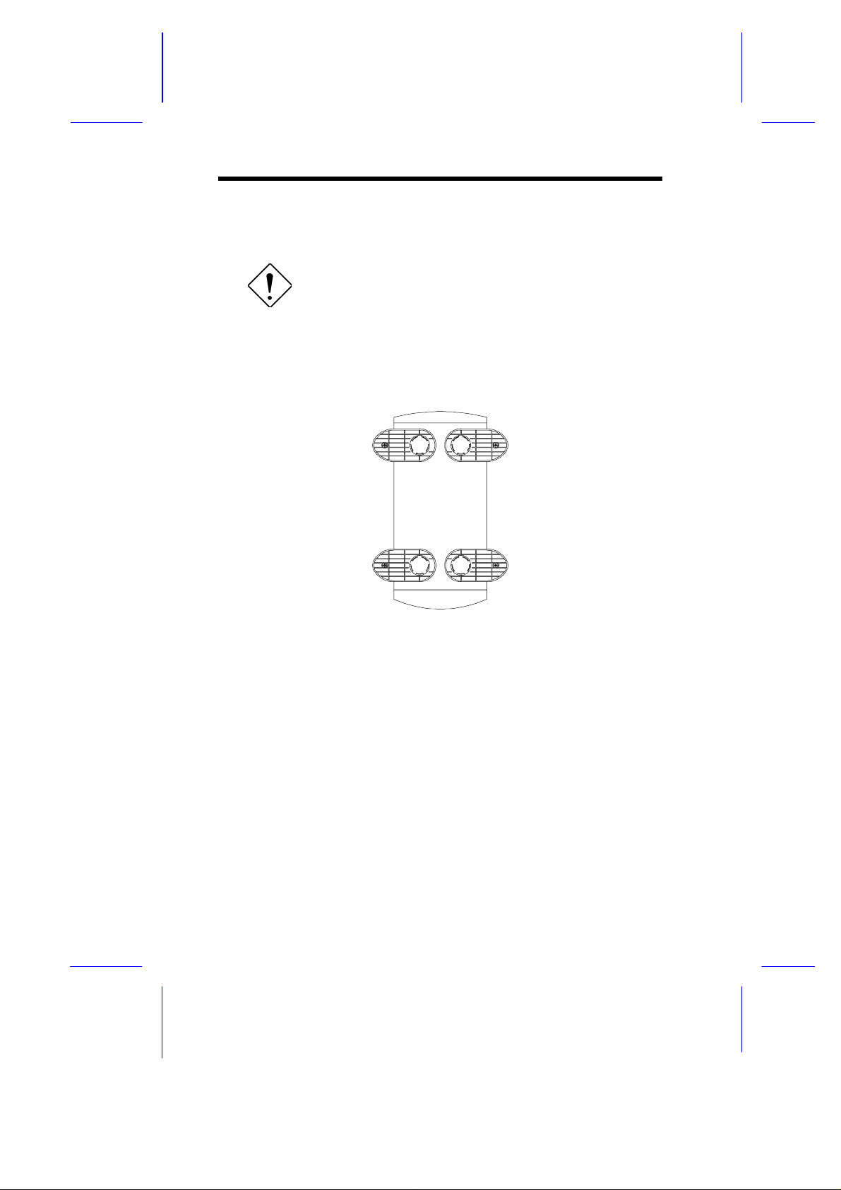
2.1 Positioning the Housing
1. Arrange the legs so that the system is secure in the standing position.
4 Installation Guide
Page 14
5 cm
A
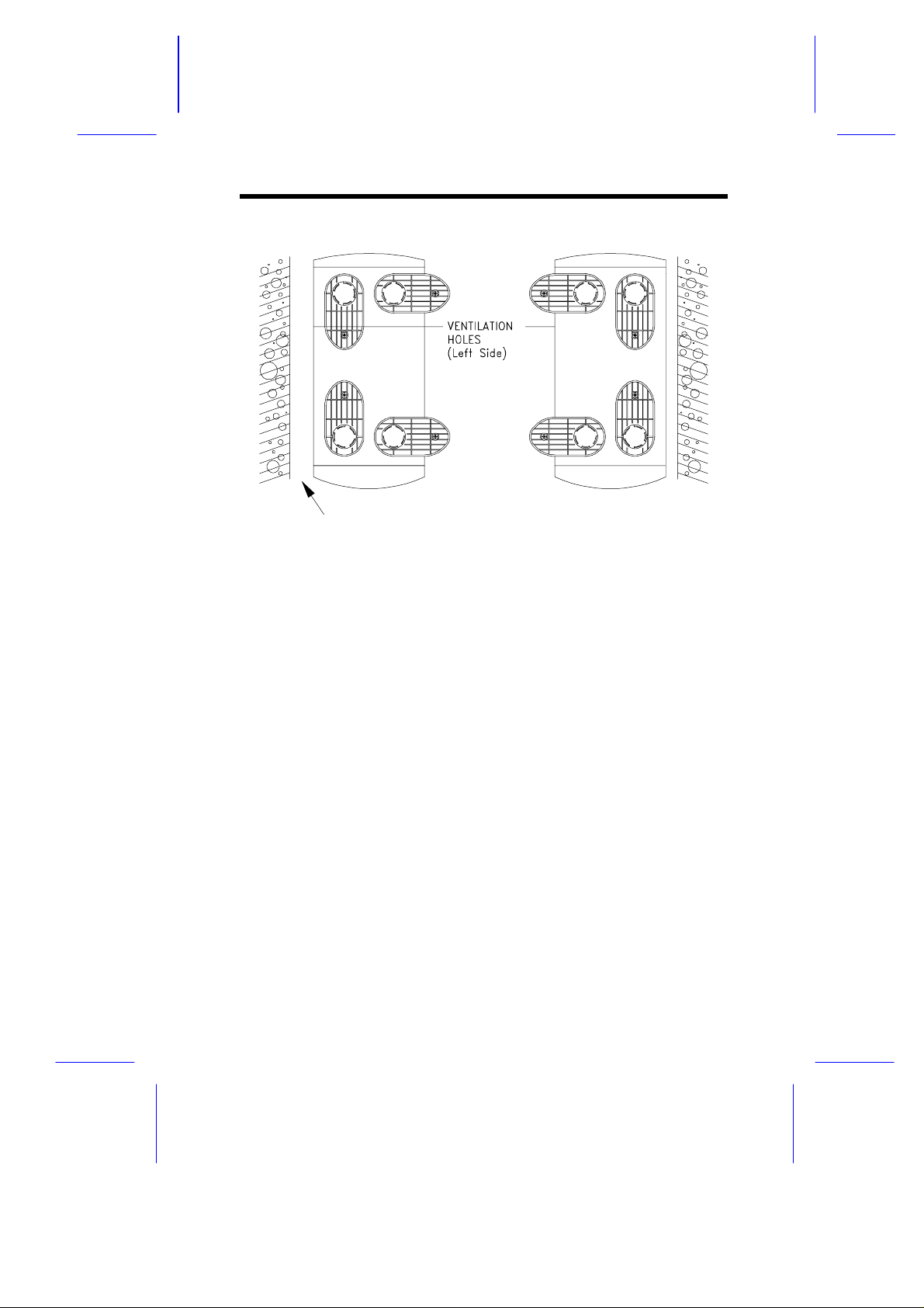
2. The housing has ventilation hol es on the left side. When standing the
system with the ventilati on hol es facing a wal l, leave a 5-cm space from
the wall to allow ai r ci r culation. See Figure A.
To stand the system with the ventilation holes facing out, place the
system close to the wall and positi on t he legs as in Figure B.
B
Aspire Minitower Housing 5
Page 15

2.2 Opening the Housi ng
1. Open the front-panel door.
2. Use a standard screwdriver or any tool with a flat end to rotate the
keylock to unlock position. Make sure that the flat end of the tool fit s
into the keylock to prevent damage such as chassis scratch.
6 Installation Guide
Page 16

4
3
3. Pull down the panel handle.
4. Pull the panel handle to release the cover from the housing frame.
5. Continue pulling until the cover is completely detached from the
housing fram e.
Aspire Minitower Housing 7
Page 17

6. Close the front-panel door. Make sure that the peg is properly inserted
into the slot.
Keep the front-panel door closed. Open it only if
necessary.
8 Installation Guide
Page 18

2.3 Installing a System Board
2.3.1 ESD Precautions
Always observe the following electrostatic discharge (ESD) precautions
before installing a system component:
1. Do not remove a component from its ant istati c packaging unt il you are
ready to install it.
2. Wear a wrist grounding strap before handling electronic components.
Wrist grounding straps are available at most electronic component
stores.
Aspire Minitower Housing 9
Page 19

2.3.2 Installation Procedures
Follow these steps to install a system boar d:
LPX slot
1. Insert the system board support s into the appropriate slots. Press t he
board supports until the holding tabs click i nt o pl ace.
10 Installation Guide
Page 20

2. Insert the connector side of the LPX board first.
3. Gently press the board until t he board holder tabs click. Make sure that
the board is properly inserted.
4. Connect the necessary cables. Be certain that all cables are secure
and properly connected before you move on.
Aspire Minitower Housing 11
Page 21

2.4 Installing Expansion Boards
Make sure that you connect all the necessary
cables to the system board before you install an
expansion board.
Observe the ESD precautions before installing a
system component.
1. Locate the expansion board slot on the system board. Insert the
expansion board golden fingers into the slot.
2. Align the expansion board with the board tabs located near the bottom
edge of the system board. G ently press the board. Make sure that the
expansion board golden fingers and the tabs are properly seated.
12 Installation Guide
Page 22

3. Remove a bracket from any empt y expansion slot. Save the screw to
secure the new board. Keep the bracket for future use.
4. Gently insert the expansion board into the expansion slot. Make sure
that the board is inserted properly.
5. Secure the board with the screw.
Do not neglect this step. The board uses the screw
for grounding.
Aspire Minitower Housing 13
Page 23

2.5 Installing Hard Disk Drives
2.5.1 Installing a Hard Disk
When you purchase a hard disk, make sure that
you have all the necessary cables to install the
drive. Don't forget to get the bad sector
information from your dealer.
1. Insert a hard disk dr i ve into t he hard dri v e bay.
2. Secure it on both sides with the necessary screws.
14 Installation Guide
Page 24

3. Connect the hard disk drive cables.
Aspire Minitower Housing 15
Page 25

2.5.2 Installing a 3.5-inch Second Hard Disk
1. Secure a 3.5-inch hard disk to the drive frame.
2. Insert the hard disk int o t he drive bay.
3. Secure the hard disk with the necessary screws.
16 Installation Guide
Page 26

4. Connect the hard disk drive cables.
Aspire Minitower Housing 17
Page 27

2.5.3 Installing a 5.25-inch Second Hard Disk
1. Insert a 5.25-i nch har d di sk into the drive bay.
2. Secure the hard disk with the necessary screws.
3. Connect the hard disk drive cables.
18 Installation Guide
Page 28

2.6 Installing the Cover
After you install t he system components into the housing, you m ust install
the cover.
To install the cover:
1. Make sure that the front-panel door is properly closed.
2. Align the rear-end corners of the cover with the front corners of the
housing fram e.
3. Push the cover back until it cli cks into place.
Always turn on any peripherals first before you turn
on the system.
Aspire Minitower Housing 19
Page 29

20 Installation Guide
 Loading...