

Acer Aspire ASX1200, Aspire ASX3200 Service Manual

Acer
Aspire ASX1200/ ASX3200
Service Guide
Service guide files and updates are available
on the ACER/CSD web; for more information,
please refer to http://csd.acer.com.tw
PRINTED IN TAIWAN

Revision History
Please refer to the table below for the updates made on ASX1200/ ASX3200 service guide.
Date Chapter Updates
ii

Copyright
Copyright © 2008 by Acer Incorporated. All rights reserved. No part of this publication may be reproduced,
transmitted, transcribed, stored in a retrieval system, or translated into any language or computer language, in
any form or by any means, electronic, mechanical, magnetic, optical, chemical, manual or otherwise, without
the prior written permission of Acer Incorporated.
iii

Disclaimer
The information in this guide is subject to change without notice.
Acer Incorporated makes no representations or warranties, either expressed or implied, with respect to the
contents hereof and specifically disclaims any warranties of merchantability or fitness for any particular
purpose. Any Acer Incorporated software described in this manual is sold or licensed "as is". Should the
programs prove defective following their purchase, the buyer (and not Acer Incorporated, its distributor, or its
dealer) assumes the entire cost of all necessary servicing, repair, and any incidental or consequential
damages resulting from any defect in the software.
Acer is a registered trademark of Acer Corporation.
AMD, the AMD Arrow logo, AMD Athlon, AMD Phenom, AMD Sempron, and combinations thereof, are
trademarks of Advanced Micro Devices Inc.
Other brand and product names are trademarks and/or registered trademarks of their respective holders.
iv

Conventions
The following conventions are used in this manual:
SCREEN
MESSAGES
NOTE Gives additional information related to the current topic.
WARNING Alerts you to any physical risk or system damage that might result from doing
CAUTION Gives precautionary measures to avoid possible hardware or software
IMPORTANT Reminds you to do specific actions relevant to the accomplishment of
Denotes actual messages that appear on screen.
or not doing specific actions.
problems.
procedures.
v

Service Guide Coverage
This Service Guide provides you with all technical information relating to the BASIC CONFIGURATION
decided for Acer's "global" product offering. To better fit local market requirements and enhance product
competitiveness, your regional office MAY have decided to extend the functionality of a machine (e.g. add-on
card, modem, or extra memory capability). These LOCALIZED FEATURES will NOT be covered in this generic
service guide. In such cases, please contact your regional offices or the responsible personnel/channel to
provide you with further technical details.
FRU Information
Please note WHEN ORDERING FRU PARTS, that you should check the most up-to-date information available
on your regional web or channel. If, for whatever reason, a part number change is made, it will not be noted in
the printed Service Guide. For ACER-AUTHORIZED SERVICE PROVIDERS, your Acer office may have a
DIFFERENT part number code to those given in the FRU list of this printed Service Guide. You MUST use the
list provided by your regional Acer office to order FRU parts for repair and service of customer machines.
vi

Table of Contents
System Tour 1
Features 1
Aspire ASX1200/3200 Tour 3
Front Panel 3
Rear Panel 4
Internal Components 5
System LED Indicators 6
System Utilities 7
Phoenix BIOS Setup Utility 7
Entering BIOS setup 8
Navigating Through the Setup Utility 8
Setup Utility Menus 9
System Disassembly 31
Disassembly Requirements 31
Pre-disassembly Procedure 32
Main Unit Disassembly 33
External Modules Disassembly Flowchart 33
Removing the Side Panel 34
Removing the Font Bezel 35
Removing the Heat Sink Fan Assembly 36
Removing the Processor 38
Removing the Optical Drive 40
Removing the Hard Disk Drive 42
Removing the Power Supply 46
Removing the Memory Modules 49
Removing the PCI Card 51
Removing the Front I/O and Card Reader Boards 53
Removing the Mainboard 57
System Troubleshooting 59
Hardware Diagnostic Procedure 59
System Check Procedures 60
Power System Check 60
System External Inspection 60
System Internal Inspection 60
POST Error and Beep Codes 61
Online Support Information 67
System Block Diagram and Board Layout 69
System Block Diagram 69
Board Layout 70
Mainboard 70
System Jumpers 71
FRU (Field Replaceable Unit) List 73
Aspire ASX1200/ ASX3200 Exploded Diagram 74
Aspire ASX1200/ ASX3200 FRU List (81.3V001.010G) 75
Technical Specifications 83
vii

viii

Chapter 1
System Tour
Features
Below is a brief summary of the computer’s many feature:
NOTE: The features listed in this section is for your reference only. The exact configuration of the server
depends on the model purchased.
Processor
T AMD Athlon LE-1600/1620/1640 processor
T AMD Athlon X2 Dual-Core BE-2300/2350/2400 or 4200+/4400+/4800+/5000+/5200+/5600+ processor
T AMD Phenom X3 Triple-Core 8400/8450/8600/8650 processor
T AMD Phenom X4 Quad-Core 9100e/9150e/9500/9550/9600/9650 processor
T AMD Sempron LE-1250/1300 or 2100 processor
Chipset
T NVIDIA nForce MCP78
Memory subsystem
T Supports up to two DDR2-667 registered ECC modules
Media storage
T DVD-ROM SATA drive
T Super-Multi SATA DVD drive
T 160 GB SATA hard disk drive
Serial ATA controller
T Embedded SATA2 controller
T Two SATA ports
Networking
T One Gigabit Ethernet LAN port (RJ-45)
PCI I/O
T One PCI Express x16 bus slot
T One PCI Express x1 bus slot
I/O ports
T Front
t Three USB 2.0 ports
t Memory Stick
t Memory Stick PRO
t Secure Digitial (SD) Card
Chapter 1 1

t miniSD Card
t Headphone/speaker-out/line-out jack
t Microphone-in jack
t CFI/II (CompactFlash Type i/II) slot
t IEEE 1394 port (4-pin)
T Rear
t PS/2 keyboard port
t PS/2 mouse port
t Line-out jack
t Microphone/speaker-out/line-in jack
t Rear speaker/surround out jack
t Center speaker/subwoofer jack
t Line-in jack
t S/PDIF port
t Four USB 2.0 ports
t eSATA port
t CRT/LCD monitor port
t HDMI port
t Gigabit LAN ports
t VGA/monitor port
t Two USB 2.0 ports
t Two Ethernet LAN ports (RJ-45)
Operating system and software
T Operating system options:
t Genuine Windows Vista
t Genuine Windows Vista Home Premium (32/64-bit)
T Applications
t Acer Empowering Technology (Acer eRecovery Management)
t Acer Arcade Live
t McAfee Internet Security Suite 2008 Trial version
t Adobe Reader
t eSobi
t NTI MediaMaker
®
Ultimate (32/64-bit)
Power supply
T 220-watts (115/230 Vac) power supply
2 Chapter 1
Aspire ASX1200/3200 Tour
This section is a virtual tour of the ASX1200/3200 system’s interior and exterior components.
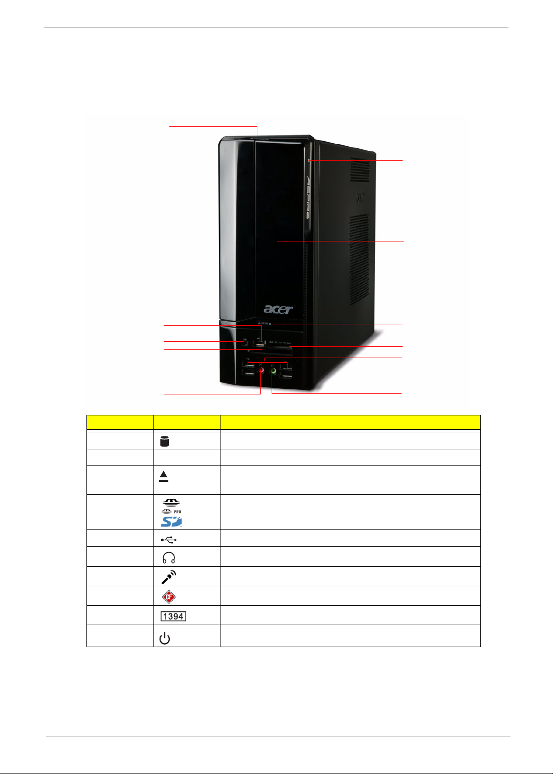
Front Panel
J
A
B
E
I
H
G
Item Icon Component
A HDD activity indicator
B Drive bay door
C Drive bay door eject button
Press to open drive bay door and access the optical drive.
D Media card reader
E USB 2.0 ports
F Headphone/Speaker-out/line-out jack
G Microphone-in jack
H CF I/II (CompactFlash Type I/II) slot
I IEEE 1394 port (4-pin)
C
D
E
F
J Power/sleep button
Chapter 1 3
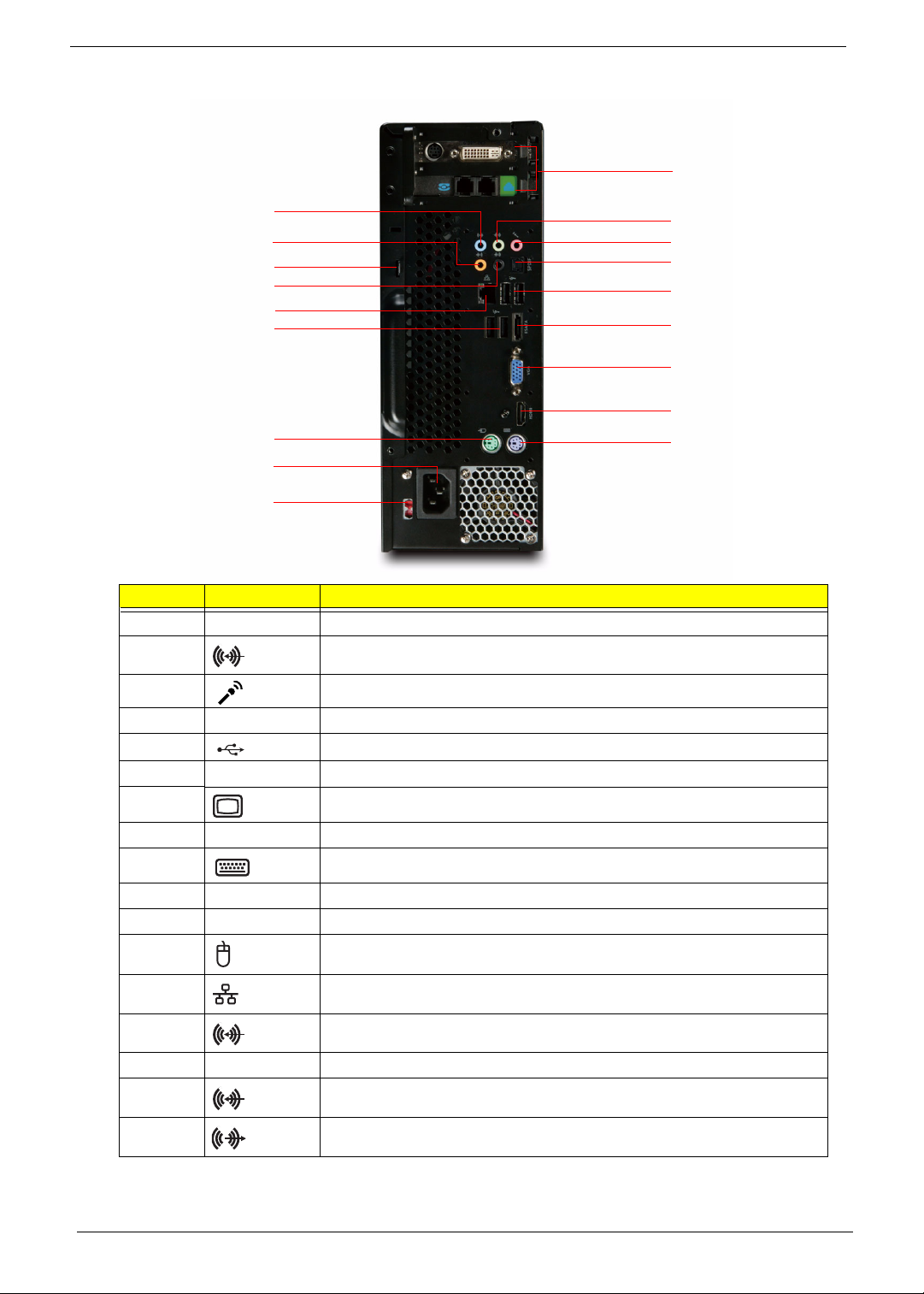
Rear Panel
A
Q
P
O
N
M
E
L
K
J
Item Icon Component
A Expansion slot (Photo shows graphics card and network/modem card)
B Line-out jack
C Microphone/speaker-out/line-in jack
B
C
D
E
F
G
H
I
D SPDIF S/PDIF port
E USB 2.0 ports
F ESATA eSATA port
G CRT/LCD monitor port
H HDMI HDMI port
I PS2 keyboard port
J Power connector
K Voltage selector switch
L PS2 mouse port
M Gigabit LAN port (10/100/1000 Mbps)
N Rear speaker/surround out jack
O Keyhole
P Center speaker/subwoofer jack
Q Line-in jack
4 Chapter 1
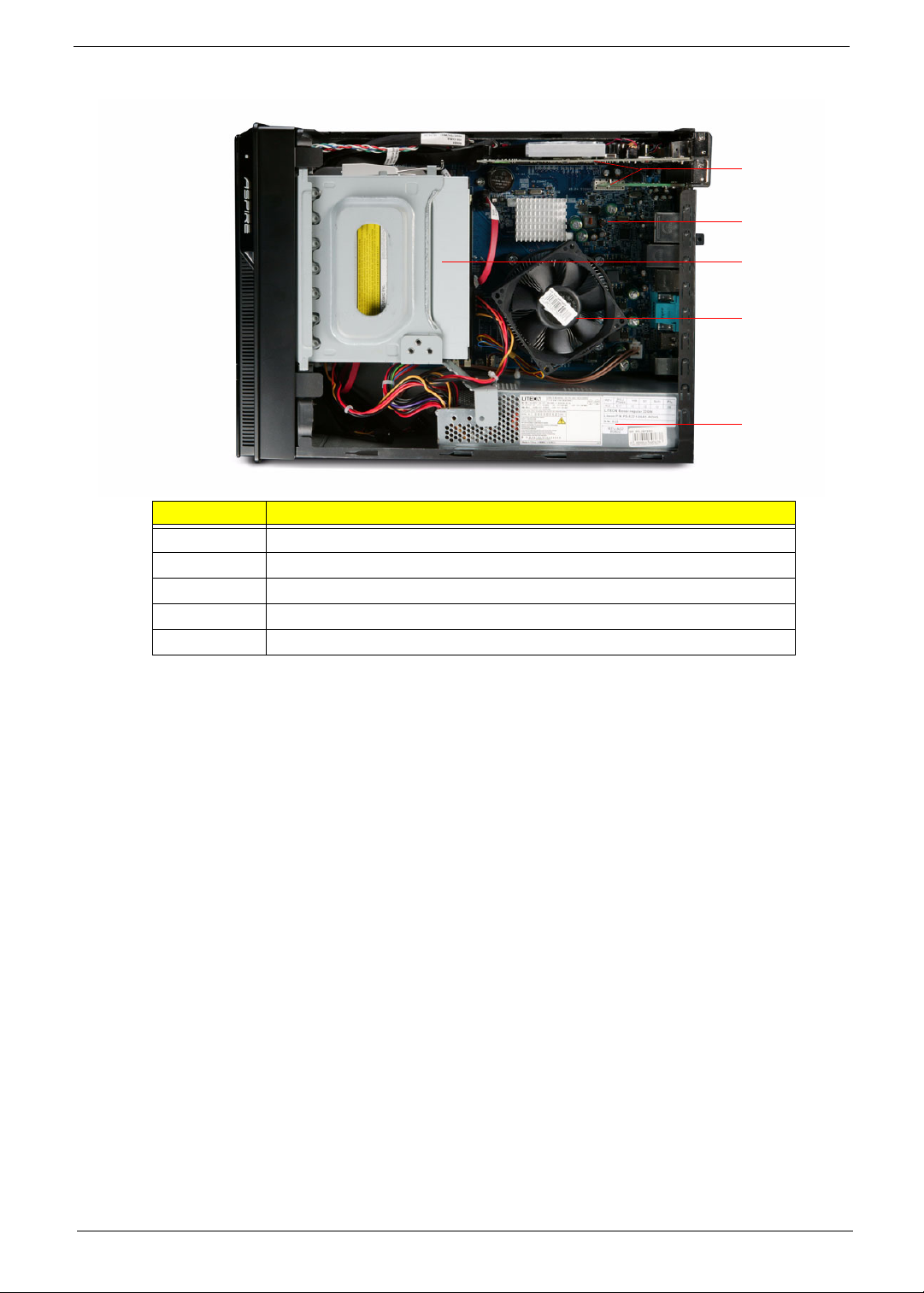
Internal Components
Item Component
A Expansion card
B Mainboard
C Optical drive
D Heat sink fan assembly
E Power supply
A
B
C
D
E
Chapter 1 5
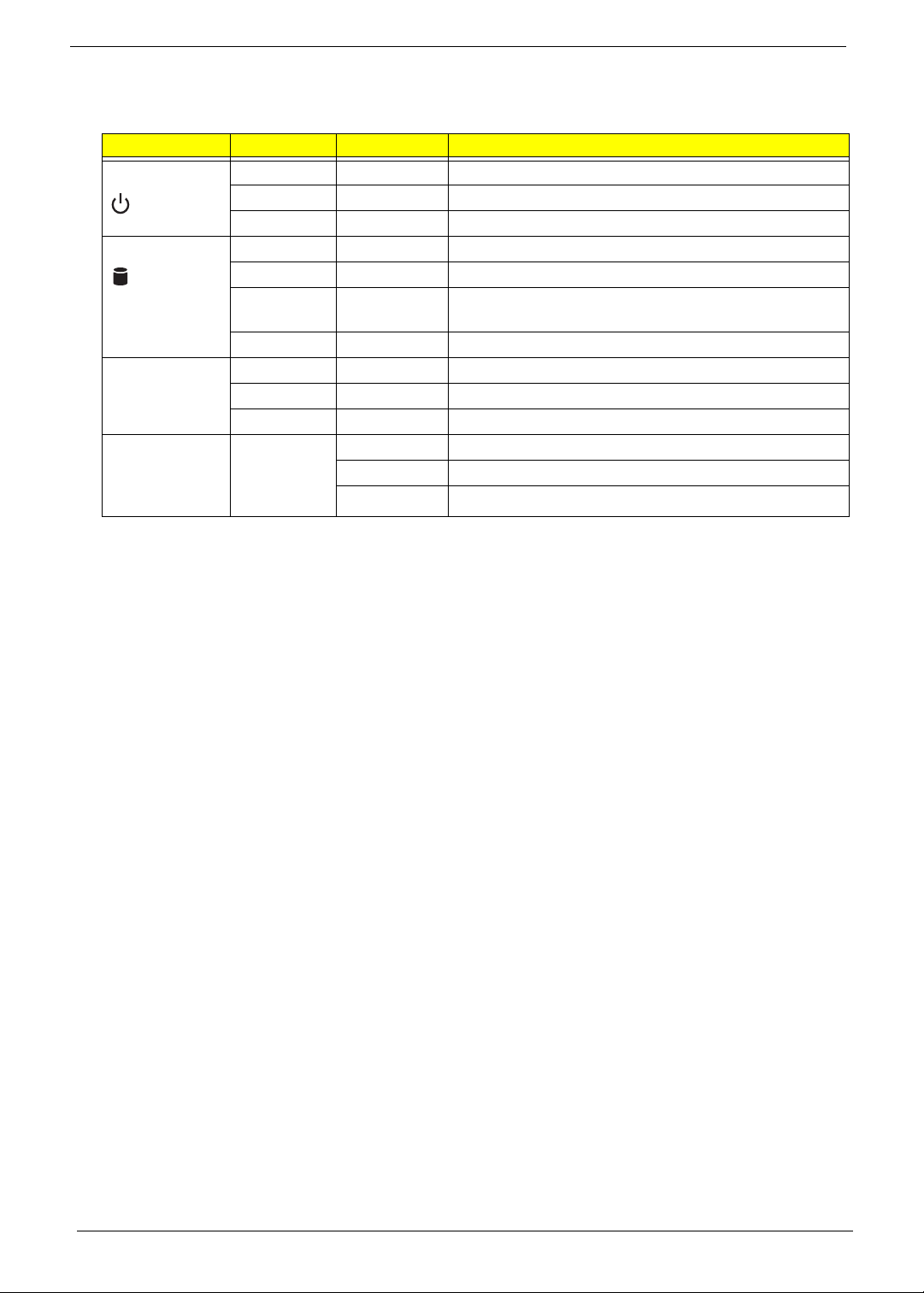
System LED Indicators
This section describes the different system LED indicators.
LED indicator Color LED status Description
Power Green On The system has AC power and is powered on.
Green Blinking The system is in standby mode.
— Off System is not powered on.
HDD activity Green On HDD is installed and functioning correctly.
Green Blinking Ongoing HDD activity.
LAN port
network speed
LED (left)
LAN port
network
connection LED
(right)
Green/
Amber
Amber On HDD failure
Amber On GbE link network access
Green On 100 Mbps link network access
— Off 10 Mbps link network access
Green On Active network link
Flashing HDD is rebuilding data.
Blinking Ongoing network data activity
Off Off-line network
6 Chapter 1

Chapter 2
System Utilities
Phoenix BIOS Setup Utility
BIOS setup is a hardware configuration program built into the system's Basic Input/Output System (BIOS).
Since most systems are already properly configured and optimized, there is no need to run this utility. You will
need to run this utility under the following conditions.
T When changing the system configuration settings
T When redefining the communication ports to prevent any conflicts
T When modifying the power management configuration
T When changing the password or making other changes to the security setup
T When a configuration error is detected by the system and you are prompted ("Run Setup"
message) to make changes to the BIOS setup
NOTE: If you repeatedly receive Run Setup messages, the battery may be bad. In this case, the system
cannot retain configuration values in CMOS. Ask a qualified technician for assistance.
BIOS setup loads the configuration values in a battery-backed nonvolatile memory called CMOS RAM. This
memory area is not part of the system RAM which allows configuration data to be retained when power is
turned off.
Before you run the PhoenixBIOS Setup Utility, make sure that you have saved all open files. The system
reboots immediately after you close the Setup.
NOTE: PhoenixBIOS Setup Utility will be simply referred to as "Setup" or "Setup utility" in this guide.
The screenshots used in this guide display default system values. These values may not be the same
those found in your system.
Chapter 2 7

Entering BIOS setup
1. Turn on the server and the monitor.
If the server is already turned on, close all open applications, then restart the server.
2. During POST, press Delete.
If you fail to press Delete before POST is completed, you will need to restart the server.
The Setup Main menu will be displayed showing the Setup’s menu bar. Use the left and right arrow keys
to move between selections on the menu bar.
Navigating Through the Setup Utility
Use the following keys to move around the Setup utility.
T Left and Right arrow keys – Move between selections on the menu bar.
T Up and Down arrow keys – Move the cursor to the field you want.
T PgUp and PgDn keys – Move the cursor to the previous and next page of a multiple page menu.
T Home – Move the cursor to the first page of a multiple page menu.
T End – Move the cursor to the last page of a multiple page menu.
T + and - keys – Select a value for the currently selected field (only if it is user-configurable). Press
these keys repeatedly to display each possible entry, or the Enter key to choose from a pop-up
menu.
NOTE: Grayed-out fields are not user-configurable.
T Enter key – Display a submenu screen.
NOTE: Availability of submenu screen is indicated by a (>).
T Esc – If you press this key:
T On one of the primary menu screens, the Exit menu displays.
T On a submenu screen, the previous screen displays.
T When you are making selections from a pop-up menu, closes the pop-up without making a
selection.
T F1 – Display the BIOS setup General Help panel.
T F5 – Press to load previous default system values.
T F6 – Press to load fail-safe default system values.
T F7 – Press to load optimized default system values.
T F10 – Save changes made the Setup and close the utility.
8 Chapter 2

Setup Utility Menus
The tabs on the Setup menu bar correspond to the six primary BIOS Setup menus, namely:
T Product Information
T Standard CMOS Features
T Advanced BIOS Features
T Advanced Chipset Features
T Integrated Peripherals
T Power Management Setup
T PnP/PCI Configurations
T PC Health Status
T Load Default Settings
T Set Supervisor Password
T Set User Password
T Save & Exit Setup
T Exit Without Saving
In the descriptive table following each of the menu screenshots, settings in boldface are the default and
suggested settings.
Chapter 2 9
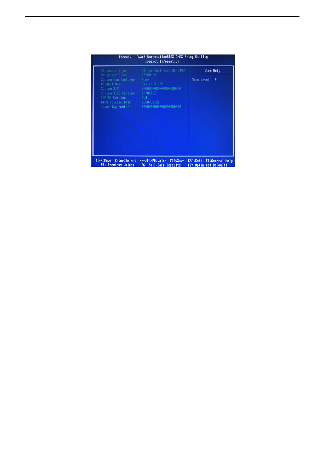
Product Information
The Product Information menu displays basic information about the system. These entries are for your
reference only and are not user-configurable.
10 Chapter 2
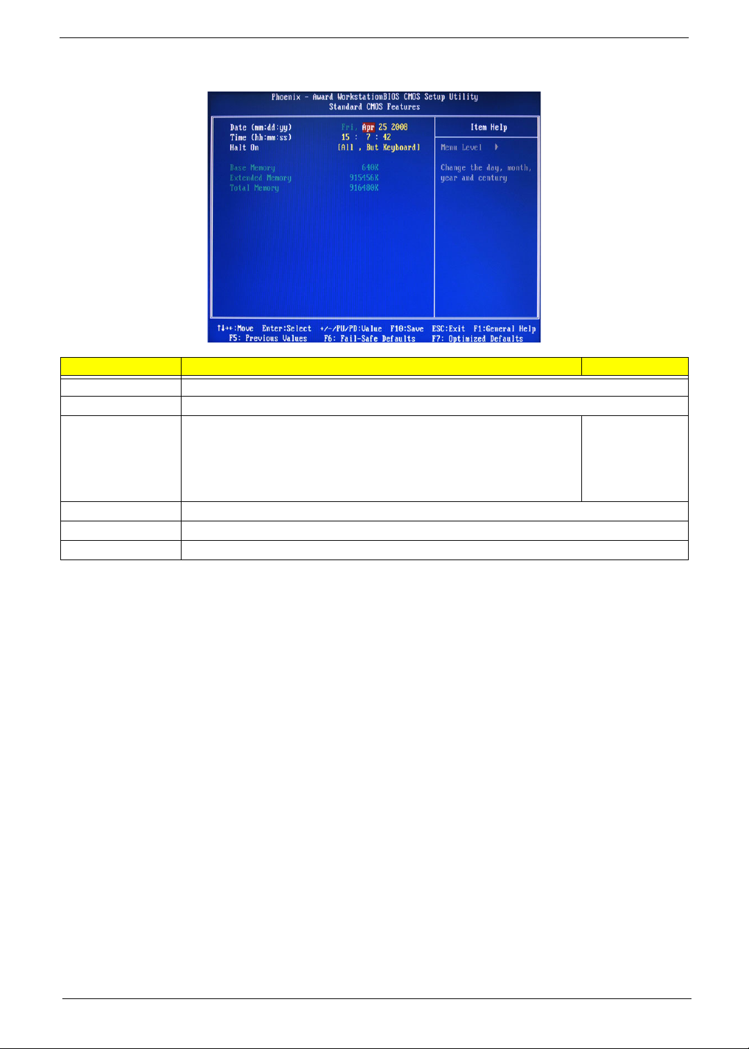
Standard CMOS Features
Parameter Description Option
Date Set the date following the weekday-month-day-year format.
Time Set the system time following the hour-minute-second format.
Halt On Determines whether the system will stop for an error during the POST. All, But Keyboard
No Errors
All Errors
All, But Diskette
All, But Disk/Key
Base Memory Also called conventional memory. Typically, 640 KB will be reserved for the MS-DOS OS.
Extended Memory Total size of extended memory detected during POST
Total Memory Total size of system memory detected during POST
Chapter 2 11
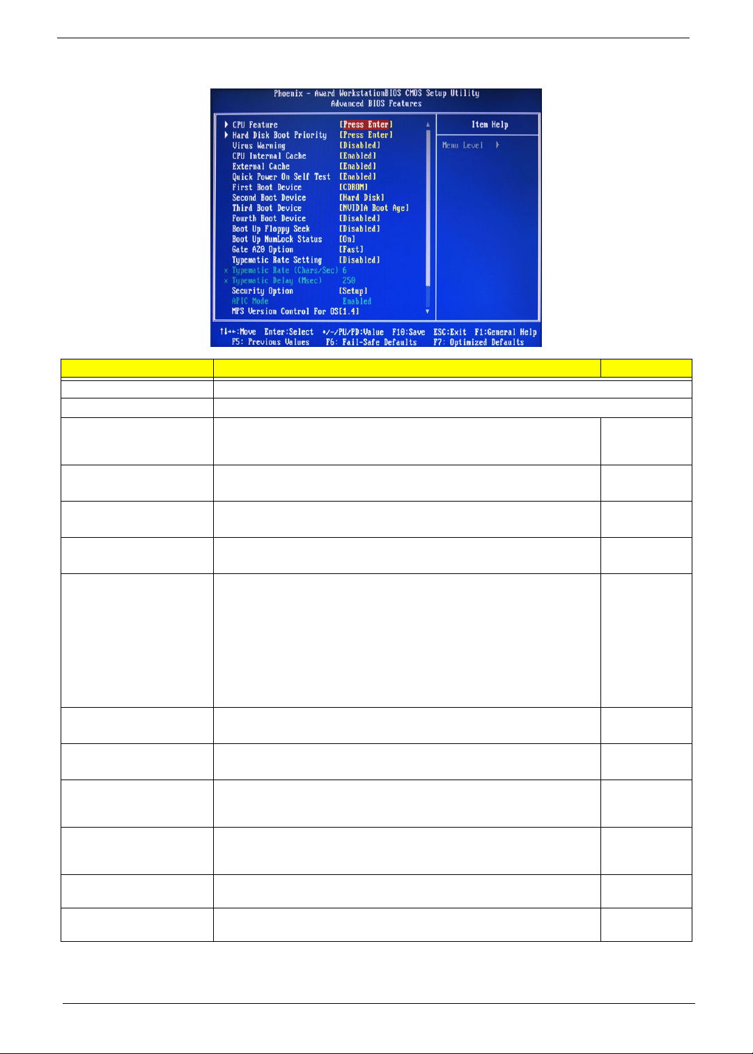
Advanced BIOS Features
Parameter Description Option
CPU Feature Press Enter to configure the CPU Virtualization and AMD K8 Cool and Quiet Control features.
Hard Disk Boot Priority Press Enter to select hard disk boot device priority.
Virus Warning Specifies the virus warning feature for IDE hard disk boot sector protection.
If enabled, BIOS will show a warning message on the screen or an alarm
beep when someone attempts to write data into this area.
CPU Internal Cache Enables or disables CPU internal cache. Enabled
External Cache Enables or disables internal cache. Enabled
Quick Power On Self Test Allows the system to skip certain test while booting. This will decrease the
First/Second/Third/Fourth
Boot Device
Boot Up Floppy Seek Enables or disables floppy drive testing to determine whether they have 40
Boot Up NumLock Status Selects power on state for Num Lock. On
Gate A20 Option When set to fast, the motherboard chipset controls the operation of Gate
Typematic Rate Setting When enabled, you can manually adjust the settings using the two typematic
Typematic Rate (Chars/Sec) Rate at which the keyboard will repeat the keystroke if you press it
Typematic Delay (MSec) Delay, in Msec, before the keyboard automatically repeats the keystroke that
time needed to boot the system.
Specifies the boot order from the available devices. CDROM, Hard
to 80 tracks.
A20. But when set to normal, a pin in the keyboard controller controls Gate
A20.
controls (Typematic Rate and Typematic Rate Delay). If disabled, the BIOS
will use the default setting.
continuously.
you have pressed continuously.
Disabled
Enabled
Disabled
Disabled
Enabled
Disabled
Disk, NVIDIA
Boot Age,
Floppy,
ZIP, USB-FDD,
USB-ZIP, USBCDROM, USBHDD, Legacy
LAN, Disabled
Disabled
Enabled
Off
Fast
Normal
Disabled
Enabled
6, 8, 10, 12, 15,
20, 24, 30
250, 500, 750,
1000
12 Chapter 2
Parameter Description Option
Security Option When set to system, BIOS will ask for the password each time the system
MPS Version Control For
OS
OS Select For DRAM > 64 MBSelect OS/2 if the system is running OS/2 operating system and the system
Full Screen Logo Show Enables or disables the display of the full screen boot logo. Enabled
Small Logo (EPA) Show Enables or disables the display of the EPA logo. Disabled
boots up.
If set to setup, the password is only required for access into the BIOS setup
menus.
Specifies the version of the Multiprocessor Specification (MPS) that the
mainboard will use.
memory is more than 64 MB in size.
Setup
System
1.4
1.1
Non-OS/2
OS/2
Disabled
Enabled
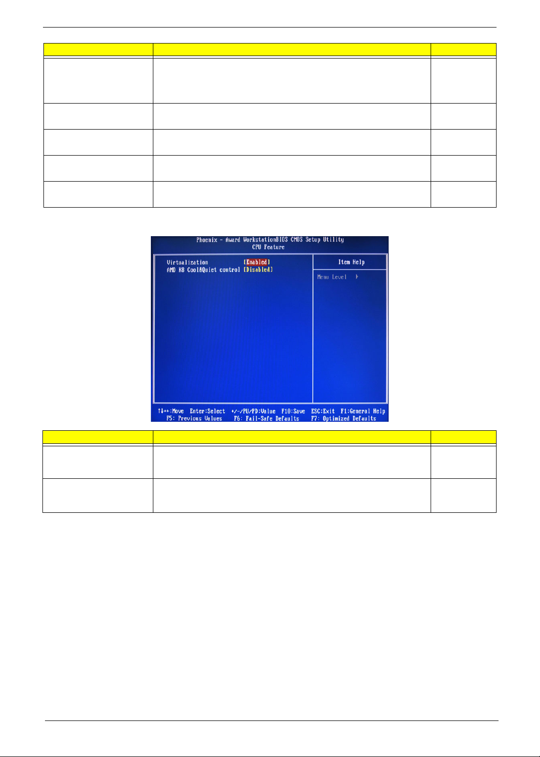
CPU Feature
Parameter Description Option
Virtualization Select whether to enable or disable the AMD Virtualization Technology (VT)
function. VT allows a single platform to run multiple operating systems in
independent partitions.
AMD K8 Cool&Quiet control When set to auto, the AMD Cool’n’Quiet driver dynamically adjust the CPU
clock and VIA to reduce heat output from your computer and its power
consumption.
Enabled
Disabled
Disabled
Auto
Chapter 2 13
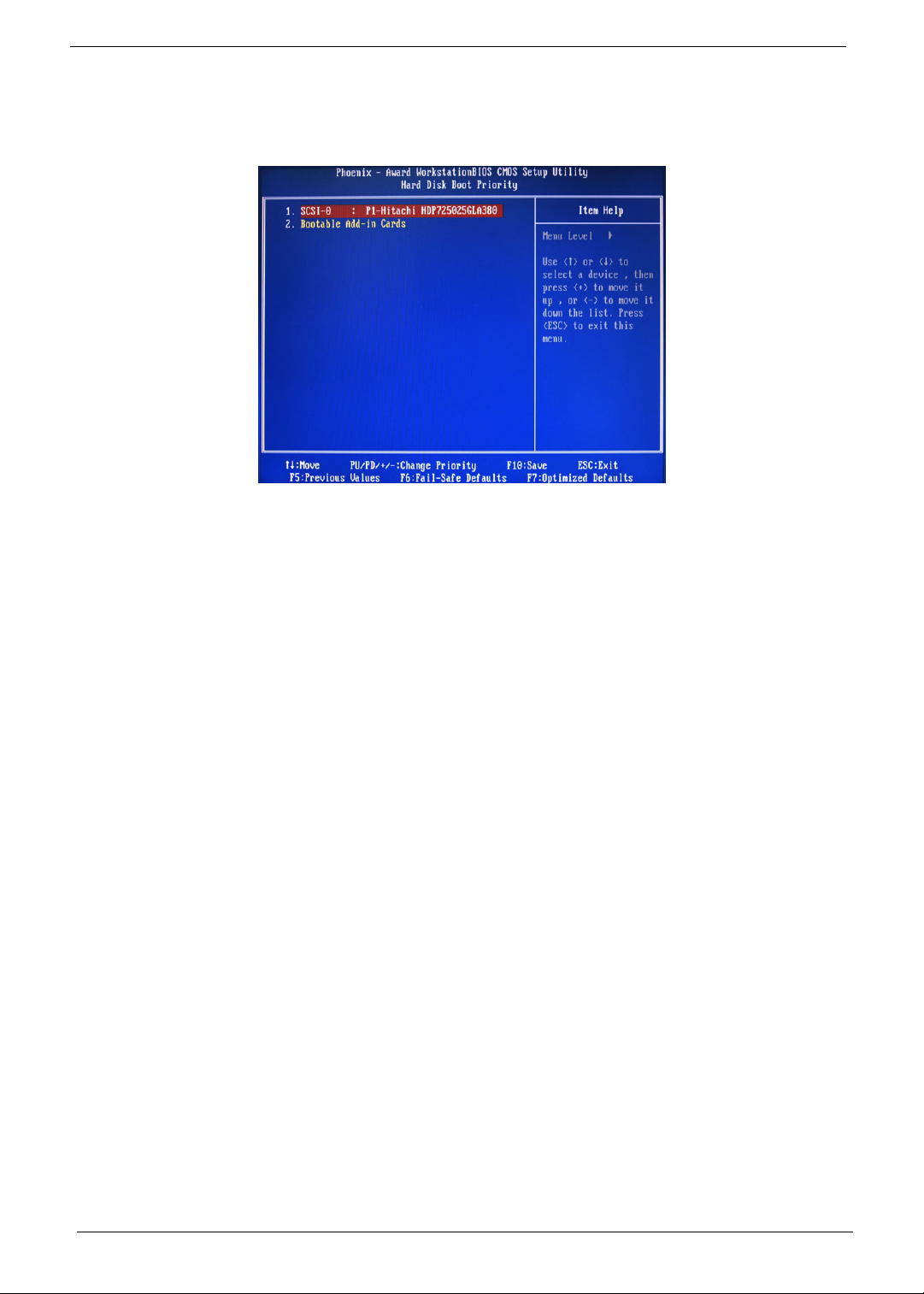
Hard Disk Boot Priority
The Hard Disk Boot Priority submenu allows you to specify the sequence of loading the OS from the installed
hard drives. Use the up or down arrow key to select a hard drive, then press the <+> key or the <-> key to
move it up or down on the list. l
14 Chapter 2
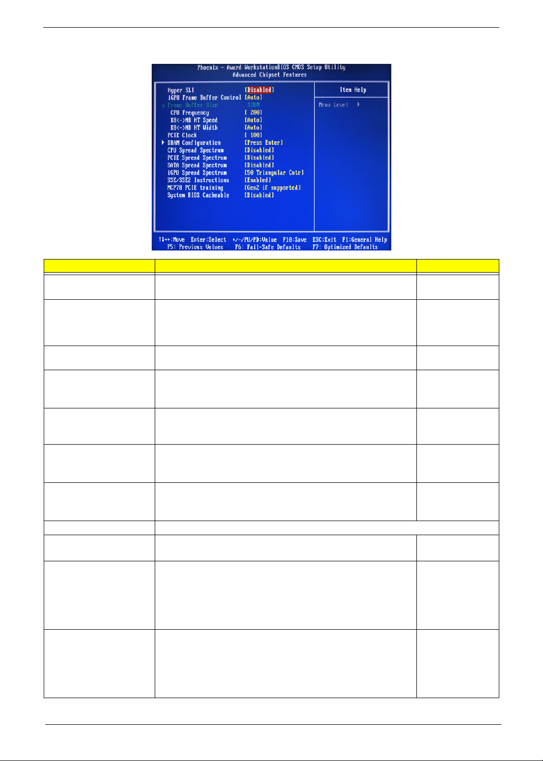
Advanced Chipset Features
Parameter Description Option
Hyper SLI Enable or disable the Scalable Link Interface (SLI) technology. Disabled
Enabled
iGPU Frame Buffer Control When set to auto, BIOS will automatically setup the frame buffer size.
When set to manual, you can set the frame buffer size. Frame buffer
size is the total amount of system memory allocated solely for the
onboard graphics controller.
Frame Buffer Size This parameter can be configured if the iGPU Frame Buffer Control is
set to Manual.
CPU Frequency Sets processor minimum and maximum frequency. 200
KB<->NB HT Speed Controls the physical speed of the processor to the Northbridge HT link. Auto
KB<->NB HT Width Controls the processor to the Northbridge link bandwidth. Auto
PCIE Clock Sets the PCI Express clock frequency. 100
DRAM Configuration Press Enter to configure memory timing and operation settings.
CPU Spread Spectrum Allows you to reduce the EMI of the front side bus by modulating the
signals it generates so that the spikes are reduced to flatter curves.
PCIE Spread Spectrum Allows you to reduce the EMI of the PCI Express bus by modulating the
signals it generates so that the spikes are reduced to flatter curves.
When set to down spread, the chipset modulates the PCI Express bus'
baseline signal downwards by a small amount.
When set to disabled, the chipset disables any modulation of the PCI
Express bus' baseline signal.
SATA Spread Spectrum Allows you to reduce the EMI of the SATA bus by modulating the
signals it generates so that the spikes are reduced to flatter curves.
When set to down spread, the chipset modulates the SATA bus'
baseline signal downwards by a small amount.
When set to disabled, the chipset disables any modulation of the SATA
bus' baseline signal.
Auto
Manual
64, 16, 32, 128,
256 MB
Minimum 100
Maximum 500
200, 400, 600, 800
MHz, 1 GHz
Up 8/16
Down 8/16
Minimum 100
Maximum 200
Disabled
-0.5%, 1.0%
Disabled
Down Spread
Disabled
Down Spread
Chapter 2 15

Parameter Description Option
iGPU Spread Spectrum Allows you to set the integrated GPU spread spectrum. 50 Triangular Cntr
100/200/300
Triangular Cntr
SSE/SSE2 Instructions Enables or disables the processor’s SSE and SSE2 instruction sets. Enabled
Disabled
MCP78 PCIE Training Cards supporting Gen2 mode will be trained in Gen2 mode. Gen2 if supported
Only Gen1
System BIOS cacheable Enables or disables the caching of the mainboard BIOS ROM from
F0000h to FFFFFh by the processor’s Level 2 cache.
Disabled
Enabled
16 Chapter 2
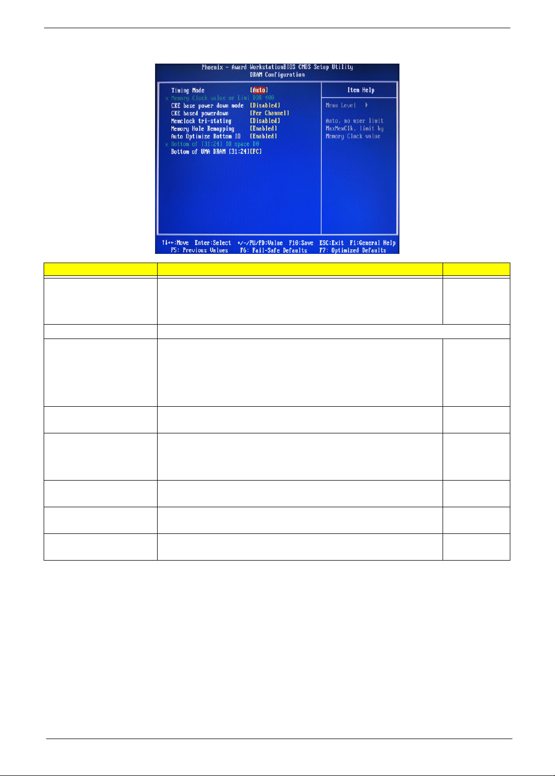
DRAM Configuration
Parameter Description Option
Timing Mode When set to auto mode, the system reads the electronic data sheet of the
Memory Clock value or Limit Displays the current memory clock frequency.
CKE base power down
mode
CKE based power down Sets the CKE power saving through disasserting clock enable using system
Memclock tri-stating Enables or disables the memory clock tri-stating during C3 an Alt VD
Memory Hole Remapping Enables or disables memory remapping around the memory hole. Enabled
Auto Optimize Bottom IO Allows you to auto optimize maximal memory size when kernel assigns PCI
Bottom of UMA DRAM
[31:24] [FC]
memory modules and adjusts the timings accordingly.
When set to MaxMemClk, you can manually specify the memory clock
frequency independent of the system bus frequency.
All synchronous memory devices can go into sleep mode as soon as the
clock enable (CKE) signal is disasserted. In that case, the internal clocks are
disabled and the memory chip goes into auto-refresh mode which is the
lowest power state at which the memory retains data.
If then power is turned off, the device will lose all data, however, as long as
standby power is maintained, no data loss will occur.
level or per channel basis.
feature.
Resources.
Allows you to enter a HEX number ranging from 0000 to 00F0. Minimim 0000
Auto
MaxMemClk
Disabled
Enabled
Per Channel
Per CS
Disabled
Memclock tristating during
C3 and Alt VD
Disabled
Enabled
Disabled
Maximum 00FC
Chapter 2 17
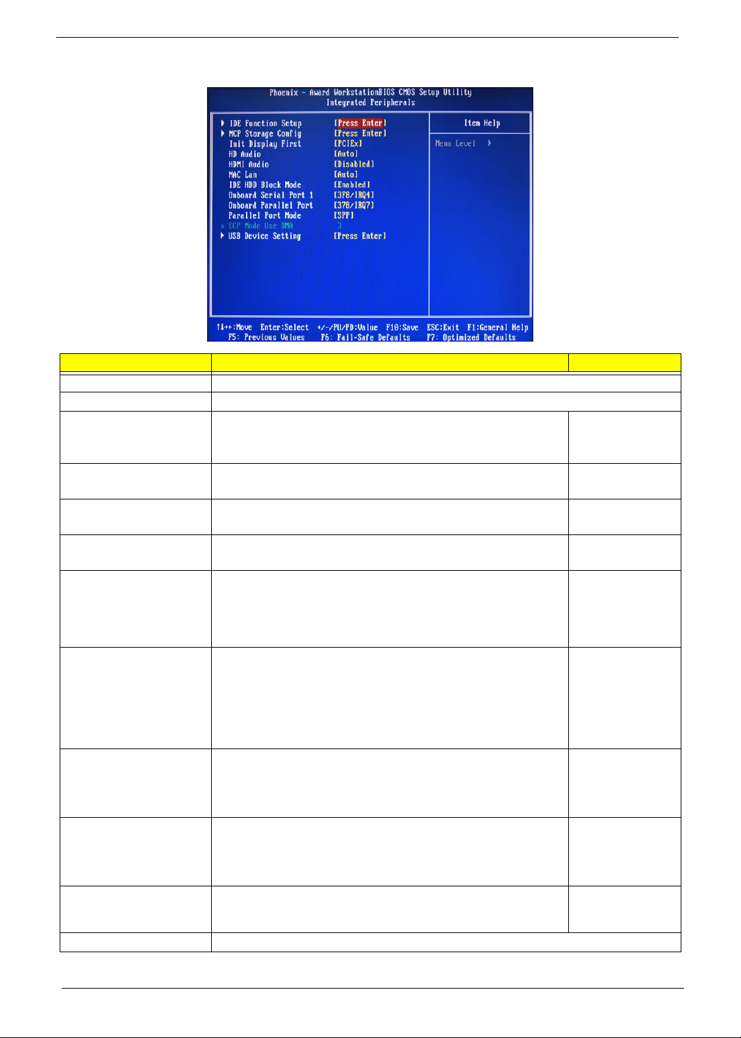
Integrated Peripherals
Parameter Description Option
IDE Function Setup Press Enter to access the IDE Function Setup submenu.
MCP Storage Config Press Enter to access the MCP Storage Config submenu.
Init Display First Select whether to boot the system using the AGP graphic card or a PCI
card installed on the PCI Express slot or PCI slot.
HD Audio Enables or disables the onboard audio controller. Auto
HDMI Audio Allows you to control the audio function of the onboard HDMI. Disabled
MAC LAN Enables or disables the built-in network interface card. Auto
IDE HDD Block Mode When enabled, the BIOS will automatically detect if your hard disk
supports block transfers and set the proper block transfer settings for it.
Depending on the IDE controller, up to 64 KB of data can be transferred
per interrupt when block transfers are enabled.
When disabled, only 512 bytes of data can be transferred per interrupt.
Onboard Serial Port 1 Select the I/O address and IRQ for the first serial port. 3F8/IRQ4
Onboard Parallel Port Select the I/O address and IRQ for the onboard parallel port. 378/IRQ7
Parallel Port Mode Select an operating mode for the onboard parallel port. SPP
ECPM Mode Use DMA Select DMA channel for the LPT port in ECP mode. This parameter can
be configured if the parallel port mode is set to ECP or ECP +EPP
mode.
USB Device Setting Press Enter to access the USB Device Setting submenu.
PCIEx
PCI Slot
Onboard
Disabled
Auto
Disabled
Enabled
Disabled
2F8/IRQ3
3E8/IRQ4
2E8/IRQ3
Auto
Disabled
278/IRQ5
3BC/IRQ7
Disabled
EPP
ECP
ECP+EPP
3
1
18 Chapter 2
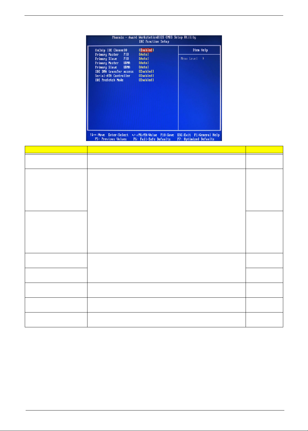
IDE Function Setup
Parameter Description Option
OnChip IDE Channel 0 Enables or disables the first IDE channel. Enabled
Disabled
Primary Master PIO
When set to Auto, BIOS setup automatically detects if the installed hard
disk supports the function. If supported, it allows for faster data recovery and
Primary Slave PIO Auto
Primary Master UDMA
Primary Slave UDMA Auto
IDE DMA Transfer Enables or disables DMA (Direct Memory Access) transfers for all IDE
Serial-ATA Controller Enables or disables the serial ATA controller. Enabled
IDE Prefetch Mode Enables or disables the IDE controller to prefetch data from the IDE drive. Enabled
read/write timing that reduces hard disk activity time. This results in better
hard disk performance. Mode 0 to 4 provide progressive increase of
performance.
Enables or disables the primary and master UDMA mode
drives.
Auto
Mode 0
Mode 1
Mode 2
Mode 3
Mode 4
Mode 0
Mode 1
Mode 2
Mode 3
Mode 4
Auto
Disabled
Disabled
Enabled
Disabled
Disabled
Disabled
Chapter 2 19
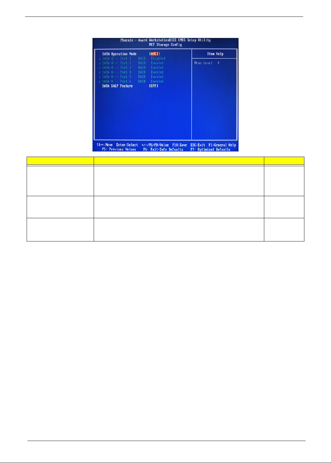
MCP Storage Config
Parameter Description Option
SATA Operation Mode Select a SATA operation mode. AHCI
IDE
RAID
Linux AHCI
SATA 0 -- Port 1 ~ 6 Enables or disables the SATA RAID on ports 1 to 6.
This parameter can be configured if the SATA Operation Mode is set to
RAID
SATA SALP Feature Select a Supports Aggressive Link Power Management (SALP) feature. Off
Disabled
Enabled
Partial
Slumber
20 Chapter 2
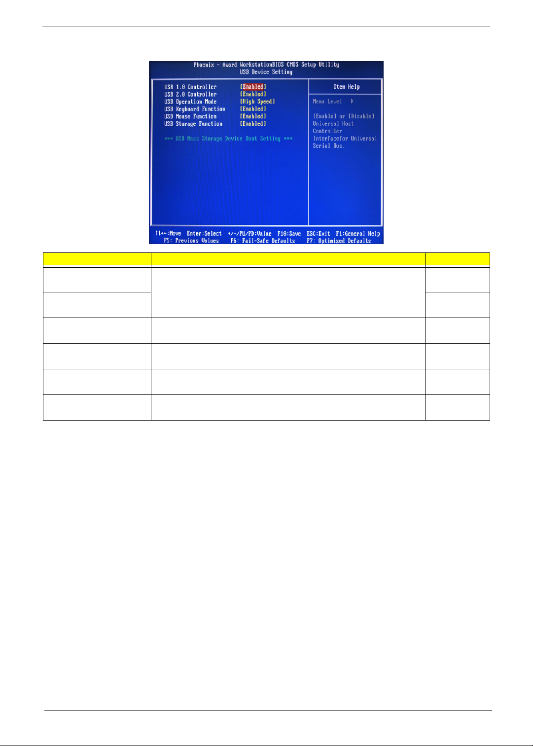
USB Device Setting
Parameter Description Option
USB 1.0 Controller
USB 2.0 Controller Enabled
USB Operation Mode Select a USB device operation speed. High Speed
USB Keyboard Function Enables or disables legacy support of the USB keyboard. Enabled
USB Mouse Function Enables or disables legacy support of the USB mouse. Enabled
USB Storage Function Enables or disables legacy support of the USB storage device. Enabled
Enables or disables the onboard USB controller.
Enabled
Disabled
Disabled
Full Low Speed
Disabled
Disabled
Disabled
Chapter 2 21
 Loading...