

Acer Aspire A515-52, Aspire A515-52G Repair Guide

Aspire A515-52/A515-52G
S E R V I C E G U I D E

Table of Contents
Chapter 1. Hardware Specifications and Configurations
Features . . . . . . . . . . . . . . . . . . . . . . . . . . . . . . . . . . . . . . . . . . . . . . . . . . . . . . . . . . . . 1-2
Notebook Tour . . . . . . . . . . . . . . . . . . . . . . . . . . . . . . . . . . . . . . . . . . . . . . . . . . . . . . . 1-6
Top View . . . . . . . . . . . . . . . . . . . . . . . . . . . . . . . . . . . . . . . . . . . . . . . . . . . . . 1-6
Left View . . . . . . . . . . . . . . . . . . . . . . . . . . . . . . . . . . . . . . . . . . . . . . . . . . . . . 1-7
Right View . . . . . . . . . . . . . . . . . . . . . . . . . . . . . . . . . . . . . . . . . . . . . . . . . . . . 1-8
Base View . . . . . . . . . . . . . . . . . . . . . . . . . . . . . . . . . . . . . . . . . . . . . . . . . . . . 1-9
Touchpad Basics . . . . . . . . . . . . . . . . . . . . . . . . . . . . . . . . . . . . . . . . . . . . . . . 1-10
Keyboard Basics . . . . . . . . . . . . . . . . . . . . . . . . . . . . . . . . . . . . . . . . . . . . . . . 1-11
System Block Diagram . . . . . . . . . . . . . . . . . . . . . . . . . . . . . . . . . . . . . . . . . . . . . . . . . 1-14
Specifications Table . . . . . . . . . . . . . . . . . . . . . . . . . . . . . . . . . . . . . . . . . . . . . . . . . . . 1-15
Chapter 2. System Utilities
BIOS Setup Utility. . . . . . . . . . . . . . . . . . . . . . . . . . . . . . . . . . . . . . . . . . . . . . . . . . . . . 2-2
Navigating the Bios Setup Utility . . . . . . . . . . . . . . . . . . . . . . . . . . . . . . . . . . . 2-2
Information Tab . . . . . . . . . . . . . . . . . . . . . . . . . . . . . . . . . . . . . . . . . . . . . . . . 2-3
Main Tab . . . . . . . . . . . . . . . . . . . . . . . . . . . . . . . . . . . . . . . . . . . . . . . . . . . . . 2-5
Advanced Tab . . . . . . . . . . . . . . . . . . . . . . . . . . . . . . . . . . . . . . . . . . . . . . . . . 2-7
Security Tab. . . . . . . . . . . . . . . . . . . . . . . . . . . . . . . . . . . . . . . . . . . . . . . . . . . 2-8
Boot Tab . . . . . . . . . . . . . . . . . . . . . . . . . . . . . . . . . . . . . . . . . . . . . . . . . . . . . 2-15
Exit Tab . . . . . . . . . . . . . . . . . . . . . . . . . . . . . . . . . . . . . . . . . . . . . . . . . . . . . . 2-17
Boot Manager . . . . . . . . . . . . . . . . . . . . . . . . . . . . . . . . . . . . . . . . . . . . . . . . . . . . . . . . 2-18
Flash Utilities. . . . . . . . . . . . . . . . . . . . . . . . . . . . . . . . . . . . . . . . . . . . . . . . . . . . . . . . . 2-19
BIOS Secure Flash Utilities . . . . . . . . . . . . . . . . . . . . . . . . . . . . . . . . . . . . . . . 2-19
DMITools Utility SOP . . . . . . . . . . . . . . . . . . . . . . . . . . . . . . . . . . . . . . . . . . . . 2-34
LAN EEPROM Utility SOP. . . . . . . . . . . . . . . . . . . . . . . . . . . . . . . . . . . . . . . . 2-50
Crisis Utility SOP . . . . . . . . . . . . . . . . . . . . . . . . . . . . . . . . . . . . . . . . . . . . . . . 2-52
BIOS Shipping Mode SOP . . . . . . . . . . . . . . . . . . . . . . . . . . . . . . . . . . . . . . . . . . . . . . 2-57
Chapter 3. Jumper and Connector Locations
Mainboard Top View. . . . . . . . . . . . . . . . . . . . . . . . . . . . . . . . . . . . . . . . . . . . . . . . . . . 3-2
Mainboard Bottom View . . . . . . . . . . . . . . . . . . . . . . . . . . . . . . . . . . . . . . . . . . . . . . . . 3-3
USB Board . . . . . . . . . . . . . . . . . . . . . . . . . . . . . . . . . . . . . . . . . . . . . . . . . . . . . . . . . . 3-4
Clear CMOS Jumper. . . . . . . . . . . . . . . . . . . . . . . . . . . . . . . . . . . . . . . . . . . . . . . . . . . 3-5
Chapter 4. Troubleshooting
General Information . . . . . . . . . . . . . . . . . . . . . . . . . . . . . . . . . . . . . . . . . . . . . . . . . . . 4-2
Power On Issues . . . . . . . . . . . . . . . . . . . . . . . . . . . . . . . . . . . . . . . . . . . . . . . 4-3
No Display Issues . . . . . . . . . . . . . . . . . . . . . . . . . . . . . . . . . . . . . . . . . . . . . . 4-4
LCD Picture Failure . . . . . . . . . . . . . . . . . . . . . . . . . . . . . . . . . . . . . . . . . . . . . 4-6
Internal Keyboard Failure. . . . . . . . . . . . . . . . . . . . . . . . . . . . . . . . . . . . . . . . . 4-7
Touchpad Failure. . . . . . . . . . . . . . . . . . . . . . . . . . . . . . . . . . . . . . . . . . . . . . . 4-7
Internal Speaker Failure. . . . . . . . . . . . . . . . . . . . . . . . . . . . . . . . . . . . . . . . . . 4-8
Internal Microphone Record Failure. . . . . . . . . . . . . . . . . . . . . . . . . . . . . . . . . 4-10
USB Failure . . . . . . . . . . . . . . . . . . . . . . . . . . . . . . . . . . . . . . . . . . . . . . . . . . . 4-11
Wireless Function Test Failure . . . . . . . . . . . . . . . . . . . . . . . . . . . . . . . . . . . . 4-12
Bluetooth Function Test Failure. . . . . . . . . . . . . . . . . . . . . . . . . . . . . . . . . . . . 4-13
SD Card Function Test Failure . . . . . . . . . . . . . . . . . . . . . . . . . . . . . . . . . . . . 4-14
Units Thermal Failure. . . . . . . . . . . . . . . . . . . . . . . . . . . . . . . . . . . . . . . . . . . . 4-15
Cosmetic Failure . . . . . . . . . . . . . . . . . . . . . . . . . . . . . . . . . . . . . . . . . . . . . . . 4-16
Other Functions Failure . . . . . . . . . . . . . . . . . . . . . . . . . . . . . . . . . . . . . . . . . . 4-17
ii

Intermittent Problems . . . . . . . . . . . . . . . . . . . . . . . . . . . . . . . . . . . . . . . . . . . . . . . . . . 4-18
Undetermined Problems . . . . . . . . . . . . . . . . . . . . . . . . . . . . . . . . . . . . . . . . . . . . . . . . 4-19
Post Codes . . . . . . . . . . . . . . . . . . . . . . . . . . . . . . . . . . . . . . . . . . . . . . . . . . . . . . . . . . 4-20
Chapter 5. Service and Maintenance
Introduction. . . . . . . . . . . . . . . . . . . . . . . . . . . . . . . . . . . . . . . . . . . . . . . . . . . . . . . . . . 5-3
Recommended Equipment . . . . . . . . . . . . . . . . . . . . . . . . . . . . . . . . . . . . . . . . . . . . . . 5-3
Maintenance Flowchart. . . . . . . . . . . . . . . . . . . . . . . . . . . . . . . . . . . . . . . . . . . . . . . . . 5-4
Getting Started . . . . . . . . . . . . . . . . . . . . . . . . . . . . . . . . . . . . . . . . . . . . . . . . . . . . . . . 5-6
Lower Case Removal. . . . . . . . . . . . . . . . . . . . . . . . . . . . . . . . . . . . . . . . . . . . 5-7
Lower Case Installation . . . . . . . . . . . . . . . . . . . . . . . . . . . . . . . . . . . . . . . . . . 5-10
Battery Removal . . . . . . . . . . . . . . . . . . . . . . . . . . . . . . . . . . . . . . . . . . . . . . . 5-12
Battery Installation . . . . . . . . . . . . . . . . . . . . . . . . . . . . . . . . . . . . . . . . . . . . . . 5-14
HDD Module Removal . . . . . . . . . . . . . . . . . . . . . . . . . . . . . . . . . . . . . . . . . . . 5-17
HDD Module Installation . . . . . . . . . . . . . . . . . . . . . . . . . . . . . . . . . . . . . . . . . 5-19
HDD Carrier Removal . . . . . . . . . . . . . . . . . . . . . . . . . . . . . . . . . . . . . . . . . . . 5-22
HDD Carrier Installation. . . . . . . . . . . . . . . . . . . . . . . . . . . . . . . . . . . . . . . . . . 5-23
USB Board Removal . . . . . . . . . . . . . . . . . . . . . . . . . . . . . . . . . . . . . . . . . . . . 5-25
USB Board Installation. . . . . . . . . . . . . . . . . . . . . . . . . . . . . . . . . . . . . . . . . . . 5-28
DIMM Modules Removal . . . . . . . . . . . . . . . . . . . . . . . . . . . . . . . . . . . . . . . . . 5-31
DIMM Modules Installation. . . . . . . . . . . . . . . . . . . . . . . . . . . . . . . . . . . . . . . . 5-32
SSD Module Removal . . . . . . . . . . . . . . . . . . . . . . . . . . . . . . . . . . . . . . . . . . . 5-33
SSD Module Installation. . . . . . . . . . . . . . . . . . . . . . . . . . . . . . . . . . . . . . . . . . 5-34
WLAN Module Removal. . . . . . . . . . . . . . . . . . . . . . . . . . . . . . . . . . . . . . . . . . 5-36
WLAN Module Installation . . . . . . . . . . . . . . . . . . . . . . . . . . . . . . . . . . . . . . . . 5-38
Fan Module Removal. . . . . . . . . . . . . . . . . . . . . . . . . . . . . . . . . . . . . . . . . . . . 5-40
Fan Module Installation . . . . . . . . . . . . . . . . . . . . . . . . . . . . . . . . . . . . . . . . . . 5-42
Thermal Module Removal . . . . . . . . . . . . . . . . . . . . . . . . . . . . . . . . . . . . . . . . 5-44
Thermal Module Installation. . . . . . . . . . . . . . . . . . . . . . . . . . . . . . . . . . . . . . . 5-46
Mainboard Removal. . . . . . . . . . . . . . . . . . . . . . . . . . . . . . . . . . . . . . . . . . . . . 5-49
Mainboard Installation . . . . . . . . . . . . . . . . . . . . . . . . . . . . . . . . . . . . . . . . . . . 5-53
DC-IN Cable Removal . . . . . . . . . . . . . . . . . . . . . . . . . . . . . . . . . . . . . . . . . . . 5-57
DC-IN Cable Installation . . . . . . . . . . . . . . . . . . . . . . . . . . . . . . . . . . . . . . . . . 5-58
RTC Battery Removal . . . . . . . . . . . . . . . . . . . . . . . . . . . . . . . . . . . . . . . . . . . 5-59
RTC Battery Installation. . . . . . . . . . . . . . . . . . . . . . . . . . . . . . . . . . . . . . . . . . 5-60
Touchpad Removal . . . . . . . . . . . . . . . . . . . . . . . . . . . . . . . . . . . . . . . . . . . . . 5-61
Touchpad Installation. . . . . . . . . . . . . . . . . . . . . . . . . . . . . . . . . . . . . . . . . . . . 5-64
Speaker Removal . . . . . . . . . . . . . . . . . . . . . . . . . . . . . . . . . . . . . . . . . . . . . . 5-68
Speaker Installation . . . . . . . . . . . . . . . . . . . . . . . . . . . . . . . . . . . . . . . . . . . . . 5-71
LCD Module Removal . . . . . . . . . . . . . . . . . . . . . . . . . . . . . . . . . . . . . . . . . . . 5-74
LCD Module Installation. . . . . . . . . . . . . . . . . . . . . . . . . . . . . . . . . . . . . . . . . . 5-77
LCD Bezel Removal. . . . . . . . . . . . . . . . . . . . . . . . . . . . . . . . . . . . . . . . . . . . . 5-81
LCD Bezel Installation . . . . . . . . . . . . . . . . . . . . . . . . . . . . . . . . . . . . . . . . . . . 5-83
CMOS and Microphone Module Removal . . . . . . . . . . . . . . . . . . . . . . . . . . . . 5-84
CMOS and Microphone Module Installation . . . . . . . . . . . . . . . . . . . . . . . . . . 5-86
LCD Panel Brackets Removal . . . . . . . . . . . . . . . . . . . . . . . . . . . . . . . . . . . . . 5-88
LCD Panel Brackets Installation . . . . . . . . . . . . . . . . . . . . . . . . . . . . . . . . . . . 5-89
LCD Panel Removal . . . . . . . . . . . . . . . . . . . . . . . . . . . . . . . . . . . . . . . . . . . . 5-91
LCD Panel Installation . . . . . . . . . . . . . . . . . . . . . . . . . . . . . . . . . . . . . . . . . . . 5-95
WLAN Antenna (Main) Removal . . . . . . . . . . . . . . . . . . . . . . . . . . . . . . . . . . . 5-99
WLAN Antenna (Main) Installation. . . . . . . . . . . . . . . . . . . . . . . . . . . . . . . . . . 5-100
WLAN Antenna (Aux) Removal . . . . . . . . . . . . . . . . . . . . . . . . . . . . . . . . . . . . 5-101
WLAN Antenna (Aux) Installation . . . . . . . . . . . . . . . . . . . . . . . . . . . . . . . . . . 5-102
iii

Chapter 6. FRU (Field Replaceable Unit) List
Exploded Diagram . . . . . . . . . . . . . . . . . . . . . . . . . . . . . . . . . . . . . . . . . . . . . . . . . . . . 6-3
Main Assembly. . . . . . . . . . . . . . . . . . . . . . . . . . . . . . . . . . . . . . . . . . . . . . . . . 6-3
Upper Cover Assembly . . . . . . . . . . . . . . . . . . . . . . . . . . . . . . . . . . . . . . . . . . 6-5
LCD Assembly . . . . . . . . . . . . . . . . . . . . . . . . . . . . . . . . . . . . . . . . . . . . . . . . . 6-6
FRU List . . . . . . . . . . . . . . . . . . . . . . . . . . . . . . . . . . . . . . . . . . . . . . . . . . . . . . . . . . . . 6-8
Screw List . . . . . . . . . . . . . . . . . . . . . . . . . . . . . . . . . . . . . . . . . . . . . . . . . . . . . . . . . . . 6-32
Chapter 7. Test Compatible Components
Microsoft® Windows® 10 Environment Test . . . . . . . . . . . . . . . . . . . . . . . . . . . . . . . . . 7-2
Aspire A515-52/A515-52G. . . . . . . . . . . . . . . . . . . . . . . . . . . . . . . . . . . . . . . . 7-2
Chapter 8. Online Support Information
Introduction. . . . . . . . . . . . . . . . . . . . . . . . . . . . . . . . . . . . . . . . . . . . . . . . . . . . . . . . . . 8-2
iv

Revision History
Please refer to the table below for the updates made on this service guide.
Date Chapter Updates
2018/08/17 Initial Release
Service guide files and updates are available on the Acer/CSD website. The information in this
guide is subject to change without notice.
Copyright
Copyright © 2018 by Acer Incorporated. All rights reserved. No part of this publication may be
reproduced, transmitted, transcribed, stored in a retrieval system, or translated into any language
or computer language, in any form or by any means, electronic, mechanical, magnetic, optical,
chemical, manual or otherwise, without the prior written permission of Acer Incorporated.
Disclaimer
The information in this guide is subject to change without notice.
Acer Incorporated makes no representations or warranties, either expressed or implied, with
respect to the contents hereof and specifically disclaims any warranties of merchantability or fitn ess
for any particular purpose. Any Acer Incorporated software described in this manual is sold or
licensed "as is". Should the programs prove defective following their purchase, the buyer (and not
Acer Incorporated, its distributor, or its dealer) assumes the entire cost of all necessary servicing,
repair, and any incidental or consequential damages resulting from any defect in the software.
Acer is a registered trademark of Acer Corporation.
Intel is a registered trademark of Intel Corporation, Inc.
Other brand and product names are trademarks and/or registered trademarks of their respective
holders.
v

Conventions
The following conventions are used in this manual:
WARNING:
Indicates a potential for personal injury.
CAUTION:
Indicates a potential loss of data or damage to equipment.
IMPORTANT:
Indicates information that is important to know for the proper completion of a
procedure, choice of an option, or completing a task.
NOTE:
Gives bits and pieces of additional information related to the curr ent topic.
The following typographical conventions are used in this document:
• Book titles, directory names, file names, path names, and program/process names are shown
in italics.
Example:
the DRS5 User's Guide
/usr/local/bin/fd
the /TPH15spool_M program
• Computer output (text that represents information displayed on a computer screen, such as
menus, prompts, responses to input, and error messages) are shown in constant width.
Example:
[01] The server has been stopped
• User input (text that represents information entered by a computer user, such as command
names, option letters, and words) are shown in constant width bold. Variables cont ained within
user input are shown in square brackets ([ ]).
Example:
At the prompt, type run [file name] -m
• Keyboard keys are shown in bold italics.
Example:
After entering data, press Enter.
• Screen output (text that represents information displayed on the system, such as menus,
prompts, responses to input, and error message s ) ar e shown in bold .
Example:
On the main menu, select OK.
vi

General Information
This Service Guide provides all technical information relating to the basic configuration for Acer's
global product offering. To better fit local market requirements and enhance product
competitiveness, your regional office may have decided to extend the functionality of a machine
(e.g. add-on card, modem, or extra memory capabilities). These localized features are not covered
in this generic service guide. In such cases, contact your regional offices or the responsible
personnel/channel to provide you with further technical details.
When ordering FRU parts:
Check the most up-to-date information available on your regional web or channel. If, for whatever
reason, a part number change is made, it may not be noted in this printed service guide.
For Acer-authorized service providers:
Your Acer office may have a different part number code than those given in the FRU list of this
printed service guide. The list provided by your regional Acer office must be used to order FRU
parts for repair and service of customer machines.
vii

CHAPTER 1
Hardware Specifications and Configurations
Hardware Specifications and Configurations . . . . . . . . . . . . . . . . .1-2
Features . . . . . . . . . . . . . . . . . . . . . . . . . . . . . . . . . . . . . . . . . . . . . . . . . . . . . . . 1-2
Notebook Tour . . . . . . . . . . . . . . . . . . . . . . . . . . . . . . . . . . . . . . . . . . . . . . . . . 1-6
Top View . . . . . . . . . . . . . . . . . . . . . . . . . . . . . . . . . . . . . . . . . . . . . . . . . . . 1-6
Left View . . . . . . . . . . . . . . . . . . . . . . . . . . . . . . . . . . . . . . . . . . . . . . . . . . . 1-7
Right View . . . . . . . . . . . . . . . . . . . . . . . . . . . . . . . . . . . . . . . . . . . . . . . . . . 1-8
Base View . . . . . . . . . . . . . . . . . . . . . . . . . . . . . . . . . . . . . . . . . . . . . . . . . . 1-9
Touchpad Basics . . . . . . . . . . . . . . . . . . . . . . . . . . . . . . . . . . . . . . . . . . . 1-10
Keyboard Basics . . . . . . . . . . . . . . . . . . . . . . . . . . . . . . . . . . . . . . . . . . . . 1-11
System Block Diagram . . . . . . . . . . . . . . . . . . . . . . . . . . . . . . . . . . . . . . . . . . 1-14
Specifications Table . . . . . . . . . . . . . . . . . . . . . . . . . . . . . . . . . . . . . . . . . . . . 1-15

Hardware Specifications and Configurations
Features
The following is a summary of the computer’s features:
Operating System
• Windows Series
• Linux
Platform
• Intel Whiskey Lake U
System Memory
DDR4 2133/2400 SODIMM memory interface design:
• DDR4 SODIMM slot x 2
• Maximum memory is up to 32GB
Display
• 15.6"
• Resolution: 1920 x 1080 (FHD) / 1366 x 768 (HD)
• TN (3.2mm) / IPS (3.2mm)
• eDP
Privacy Control
• BIOS user, supervisor, HDD passwords
• Kensington lock slot
Hardware Specifications and Configurations 1-2
Storage Subsystem
• SATA HDD/SSD
HDD 7.0mm
M.2 SSD
• SD Card
Secure Digital™ (SD) Card, Mini SD™, Micro SD™, SDXC™, SDHC
• Specification: SD 3.0 (Maximum support capacity up to 2GB)
Type Model Test Result
SDHC Toshiba 4GB(Class 4) Pass
SDHC Toshiba 32GB(Class 4) Pass
SDHC SanDisk 32GB(Class 4) Pass
SDHC SanDisk 4GB(Class 6) Pass
SDHC Transcend 4GB(Class 6) Pass
SDHC SAMSUNG 16GB(Class 6) Pass
SDHC ADATA 16GB(Class 10) Pass
SDHC Transcend 8GB(Class 10) Pass
SDHC Toshiba 16GB(Class 10) Pass
SDHC Kingston 16GB(Class 10) Pass
SDXC Sandisk 64GB(Class 10) Pass
SDXC Transcend 64GB(Class 10) Pass
Graphics
• nVidia MX130 - 2GB VRAM
• nVidia MX150 - 2GB VRAM
Audio Subsystem
• Codec: Realtek ALC255-CG
• Speaker x 2
• Audio Jack x 1
• Dual digital MIC on Camera Module
1-3 Hardware Specifications and Configurations

Communication
Webcam
• HD Camera
Wireless
• 802.11 AC/BGN +BT
Dimensions and Weight
Dimension
• 363.4 (L) x 247.5 (W) x 18.85 (H) mm (14.31 (L) x 9.74 (W) x 0.74 (H) inches)
Weight
• 1.9kg (4.2lbs)
Power Adapter and Battery
Battery
• 4-cell, 3320/3220 mAh Li-Ion battery
Power Adapter
• 65W AC adapter
I/O Ports
• One DC-in jack for AC adapter
• One USB 3.0 port (Support offline charging)
• One USB 3.1 Type-C Gen1 port
• Two USB 2.0 ports
• One HDMI port
• One LAN port
• One Headphone jack
• One Card Reader
• One Kensington Lock
Hardware Specifications and Configurations 1-4

Special Keys and Controls
Control Buttons
• Power button x1 (embedded on the keyboard)
Keyboard
• Phantom key auto detection
• Supports independent pgdn/pgup/home/end keys
• Support reverse T cursor keys
Touchpad
• Precision touchpad
Environment
Temperature
• Operating: 0ºC to 40ºC (32°F to 104°F)
• Non-operating: -20ºC to 60ºC (-4°F to 140°F)
Humidity (non-condensing)
• Operating: 0%R.H to 80%R.H
• Non-operating: 0%R.H to 80%R.H
Warranty
• One-year International Tra vellers Warranty (ITW)
Accessories
• 65W AC adapter
• Manual Kits
• Power cord
1-5 Hardware Specifications and Configurations
Notebook Tour
6
1
2
3
4
5
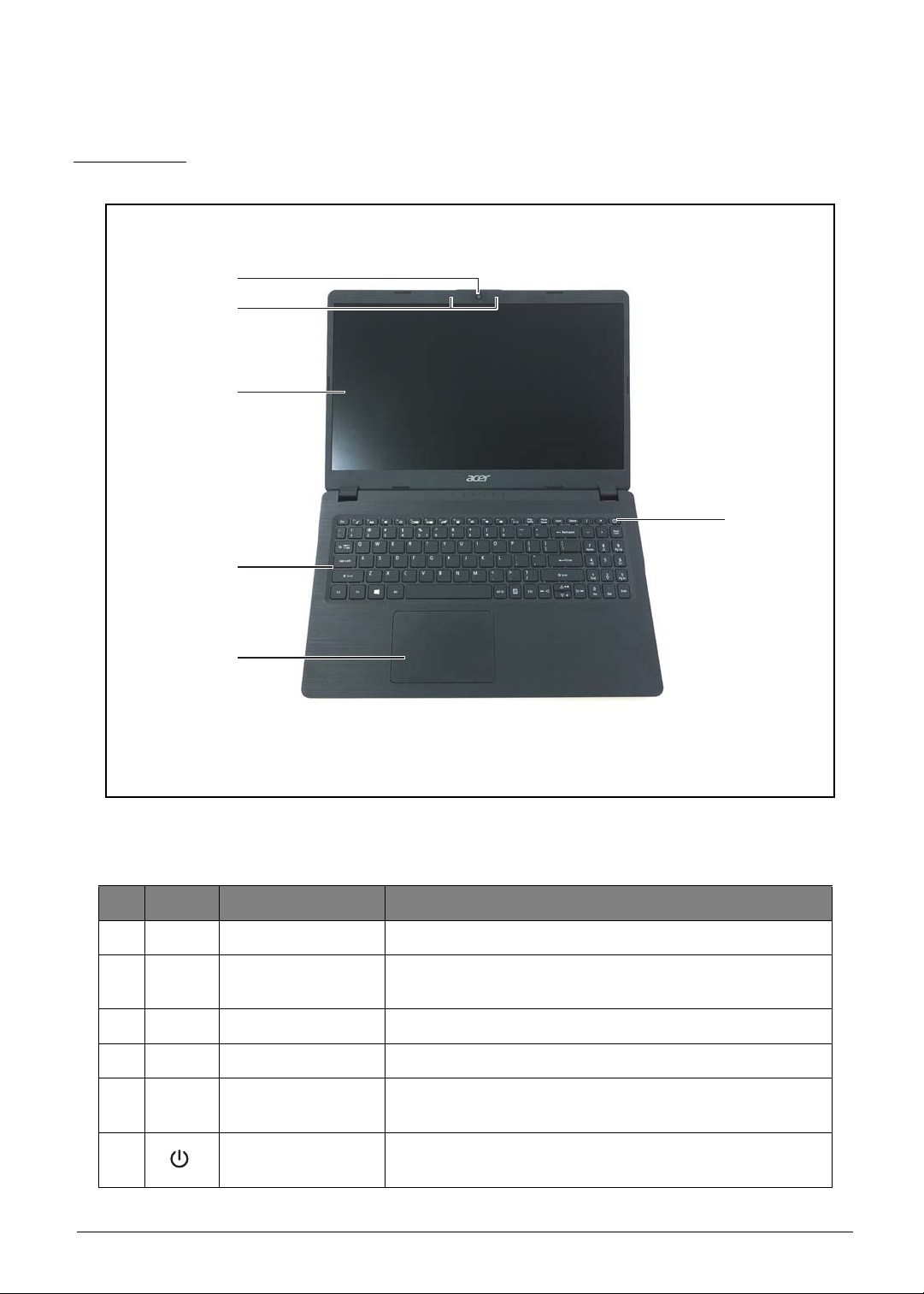
Top View
Figure 1-1. Top View
# Icon Item Description
1 Webcam Web camera used for video communications.
2 Microphones
3 Display Screen Displays the screen output.
4 Keyboard Use to enter data into the computer.
5 Touchpad
6 Power Button
Hardware Specifications and Configurations 1-6
Table 1-1. Top View
Receives audio input for sound recording or voice
chatting
Touch-sensitive pointing device that functions like a
computer mouse.
Press to turn on the system on or off. The indicator lights
blue when the power is on.
Left View
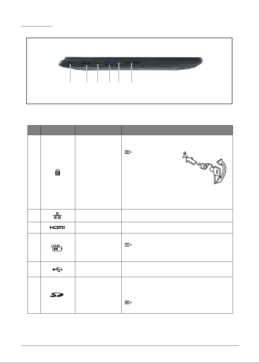
123456
Figure 1-2. Left View
Table 1-2. Left View
# Icon Item Description
Connects to a Kensington-compatible computer
security lock.
NOTE:
Wrap the computer
security lock cable
1 Kensington Lock
around an
immovable object
such as a table or
handle of a locked
drawer. Insert the lock into the notch and turn
the key to secure the lock. Some keyless
models are also available.
2 LAN Port Connects to a local area network.
3 HDMI Port Supports high-definition digital video conn ections.
Connects to USB 3.0 Super Speed (USB) device.
4 USB 3.0 Port
5
6 Card Reader
1-7 Hardware Specifications and Configurations
USB 3.1 Type-C
Port
NOTE:
Devices without USB 3.0 certification may not
be compatible.
Connects to USB 3.1 Type-C compatible devices.
Insert a memory card such as
(SD), Mini SD
for external storage.
NOTE:
Only one card can be inserted at one time.
TM
, Micro SDTM, SDXCTM, SDHC
Secure DigitalTM
Right View
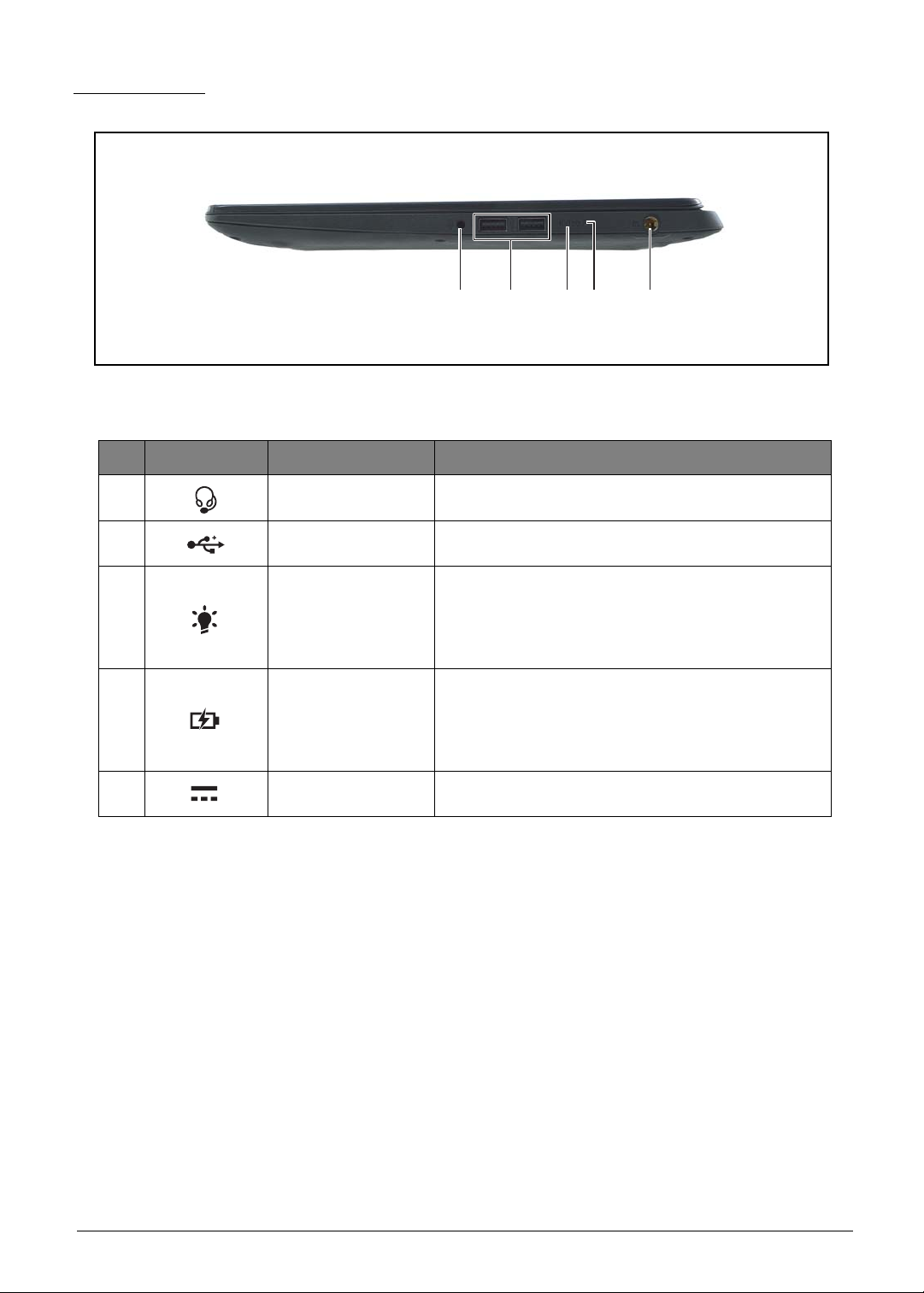
12 34 5
Figure 1-3. Right View
Table 1-3. Right View
# Icon Item Description
1 Audio Jack Connects to a headset.
2 USB 2.0 Ports Connects to USB 2.0 devices .
Indicates the computer power status:
3 Power Indicator
4 Battery Indicator
5 DC-In Jack Connects to an AC adapter.
• Off: System is off.
• Blue: System is on.
• Orange (flashing): S3 state
Indicates the computer battery status:
• Orange (flashing): Battery low.
• Orange: Battery is charging.
• Blue: Battery is fully charged.
Hardware Specifications and Configurations 1-8
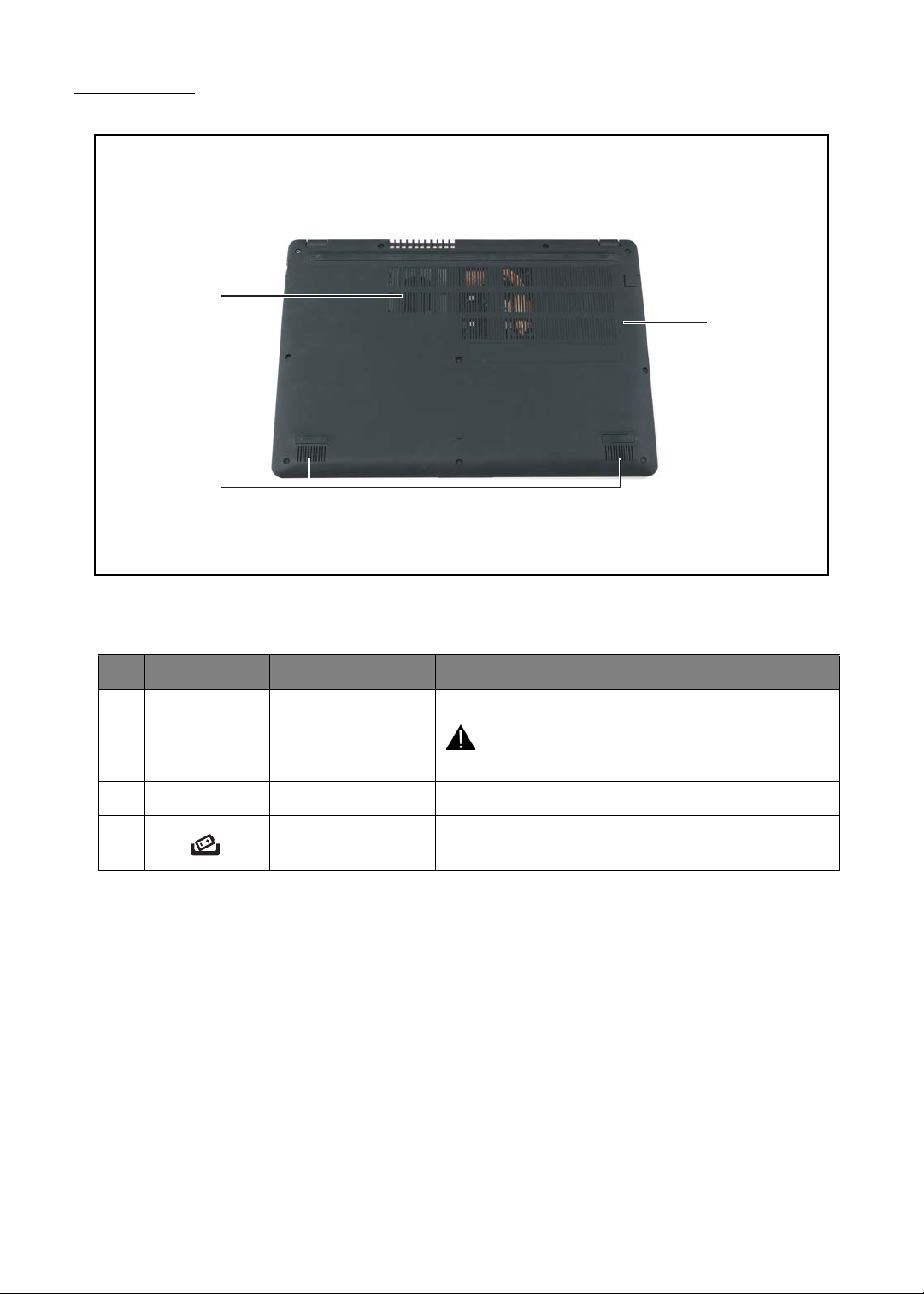
Base View
1
2
3
Figure 1-4. Base View
Table 1-4. Base View
# Item Description
Use for air flow.
1 Air Vents
2 Speakers Emits audio sound.
3 Reset Button
CAUTION:
Do not cover the air vents.
Insert a suitable tool into the hole to reset the
device.
1-9 Hardware Specifications and Configurations
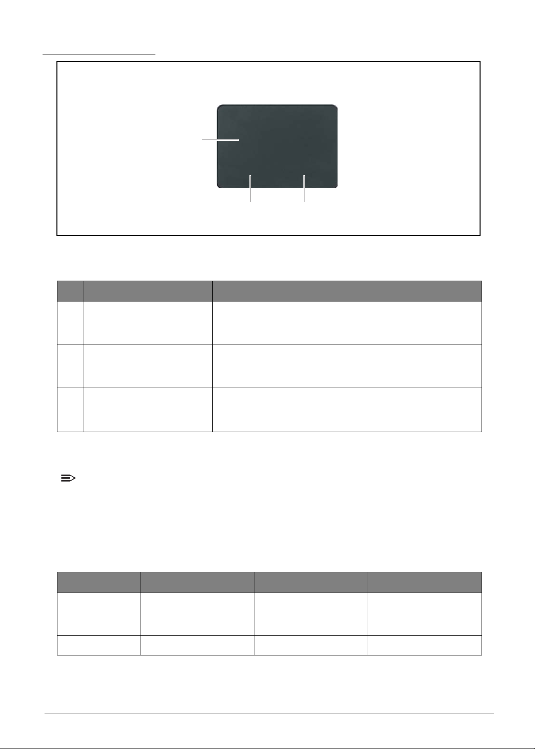
Touchpad Basics
2
1
3
Figure 1-5. Touchpad
Table 1-5. Touchpad
# Item Description
Move your finger across the touchpad to move the cursor.
1 Touchpad
Tapping on the touchpad is the same as clicking the lef t
mouse button.
Press on the bottom left side of the touchpad to perform
2Left Click
3 Right Click
selection and execution functions. This button is equivalent
to the left button on a mouse.
Press on the bottom right side of the touchpad to perform
selection and execution functions. This button is equivalent
to the right button on a mouse.
Using the Touchpad
NOTE:
• The touchpad is sensitive to finger movement s; hence, the lighter the touch, the be tter the
response. Tapping too hard will not increase the touchpad sensitiveness.
• When using the touchpad, keep the touchpad and your fingers dry and clean.
Below is a description of basic touchpad operations:
Table 1-6. Touchpad Operations
Function Touchpad Bottom Left Side Bottom Right Side
T ap twice (same speed
Execute
as double-clicking a
mouse button).
Quickly click twice.
Select Tap once. Click once.
Hardware Specifications and Configurations 1-10
Function Touchpad Bottom Left Side Bottom Right Side
1
23 4
Drag
Access context
menu
Keyboard Basics
Tap twice; on the
second tap, rest your
finger on the touchpad
and drag the cursor.
Press and hold, then
use your finger on the
touchpad to drag the
cursor.
Click once.
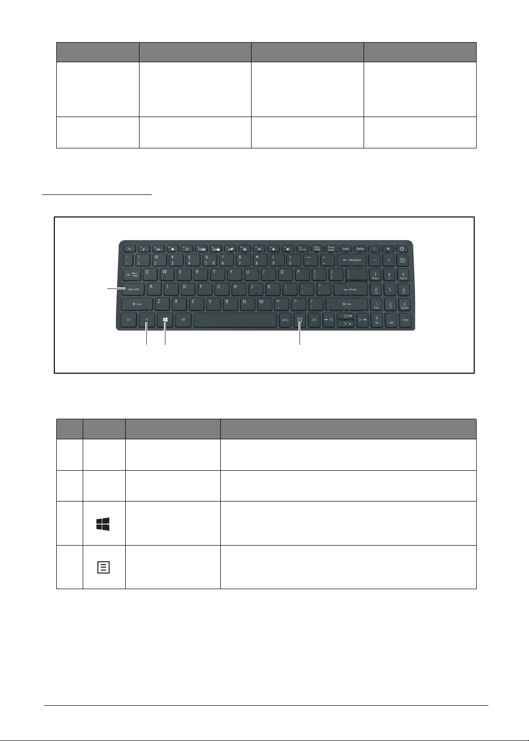
Figure 1-6. Keyboard
Table 1-7. Keyboard
# Icon Item Description
1 Caps Lock Key
2
3 Windows Key
4 Application Key
Fn
Function Key
When Caps Lock is on, all alphabetic characters are
typed in uppercase.
Use with other key combinations to perform special
functions.
• Press to launch the Start menu.
• When used with other keys, provides a variety of
functions. See Windows Key on page 1-12.
Press to open the context menu of the current
application. This key has the same effect as clicking the
right mouse button.
1-1 1 Hardware Specifications and Configurations
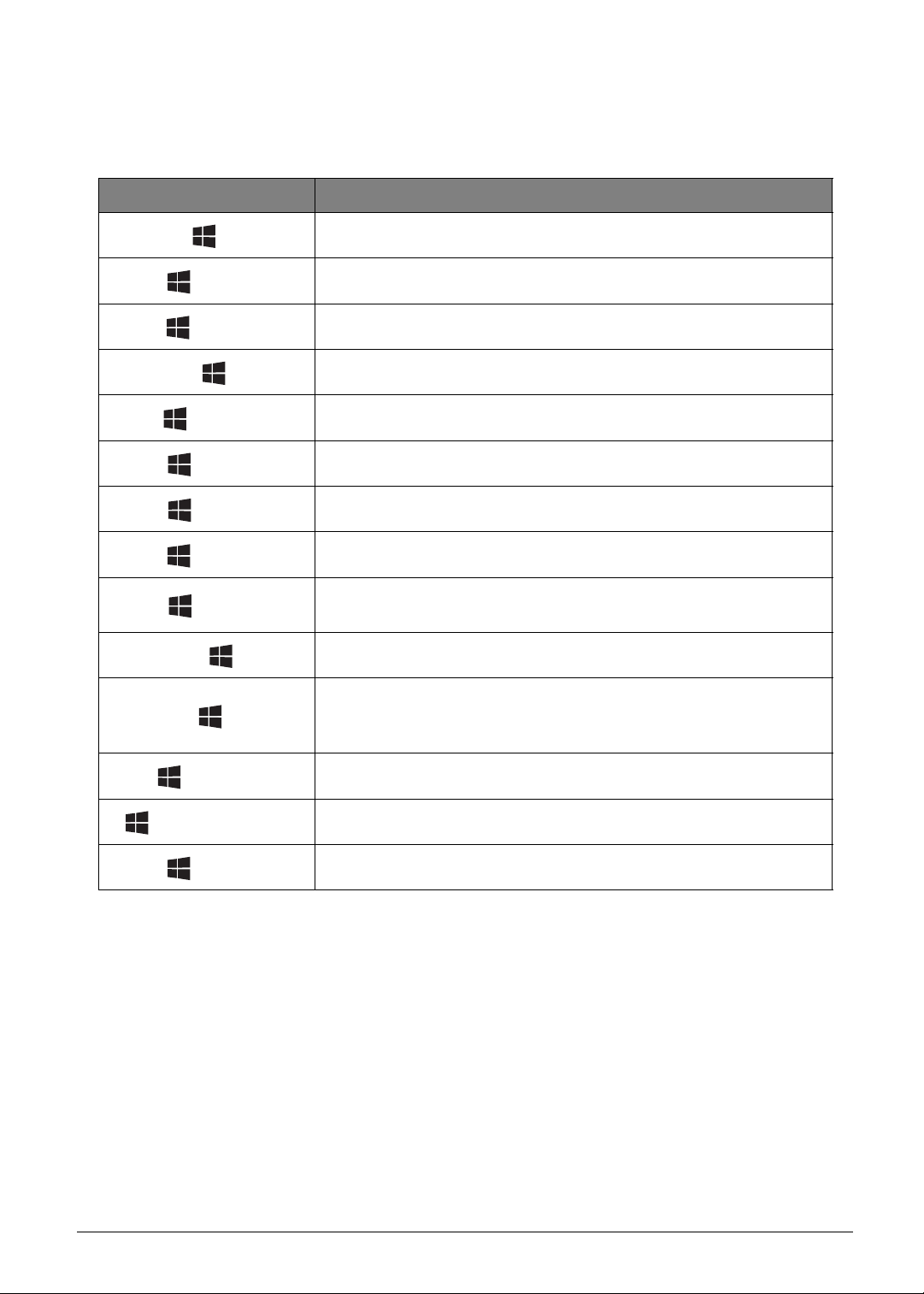
Windows Key
The table below shows the different functions that Windows key combinations can do:
Table 1-8. Windows Key Combinations
Key Combination Description
Opens or closes the Start menu.
+ <R>
+ <M>
<Shift> + + <M>
+ <F1>
+ <E>
+ <F>
+ <D>
+ <L>
<CTRL> + + <F>
<CTRL> + + <TAB>
+ <TAB>
Opens the Run dialog box.
Minimizes all windows.
Undo immunize all windows.
Shows the help window.
Opens Windows Explorer.
Searches for a file or folder.
Shows the desktop.
Locks the computer (if you are connected to a network dom ain), or
switch users (if you are not connected to a network domain).
Searches for computers (if you are on a network).
Moves focus from the Start menu to the Quick Launch toolbar and
to the system tray. Use the right and left arrow keys to move focus
to items on the Quick Launch toolbar and the system tray.
Cycles through programs on the toolbar.
+ <Pause Break>
+ <U>
Hardware Specifications and Configurations 1-12
Displays the system properties dialog box.
Opens Ease of Access Center (for Windows XP only).
Hotkeys
Hotkeys or function key combinations can be used to access computer control functions such as
screen brightness, volume, and multimedia playback controls.
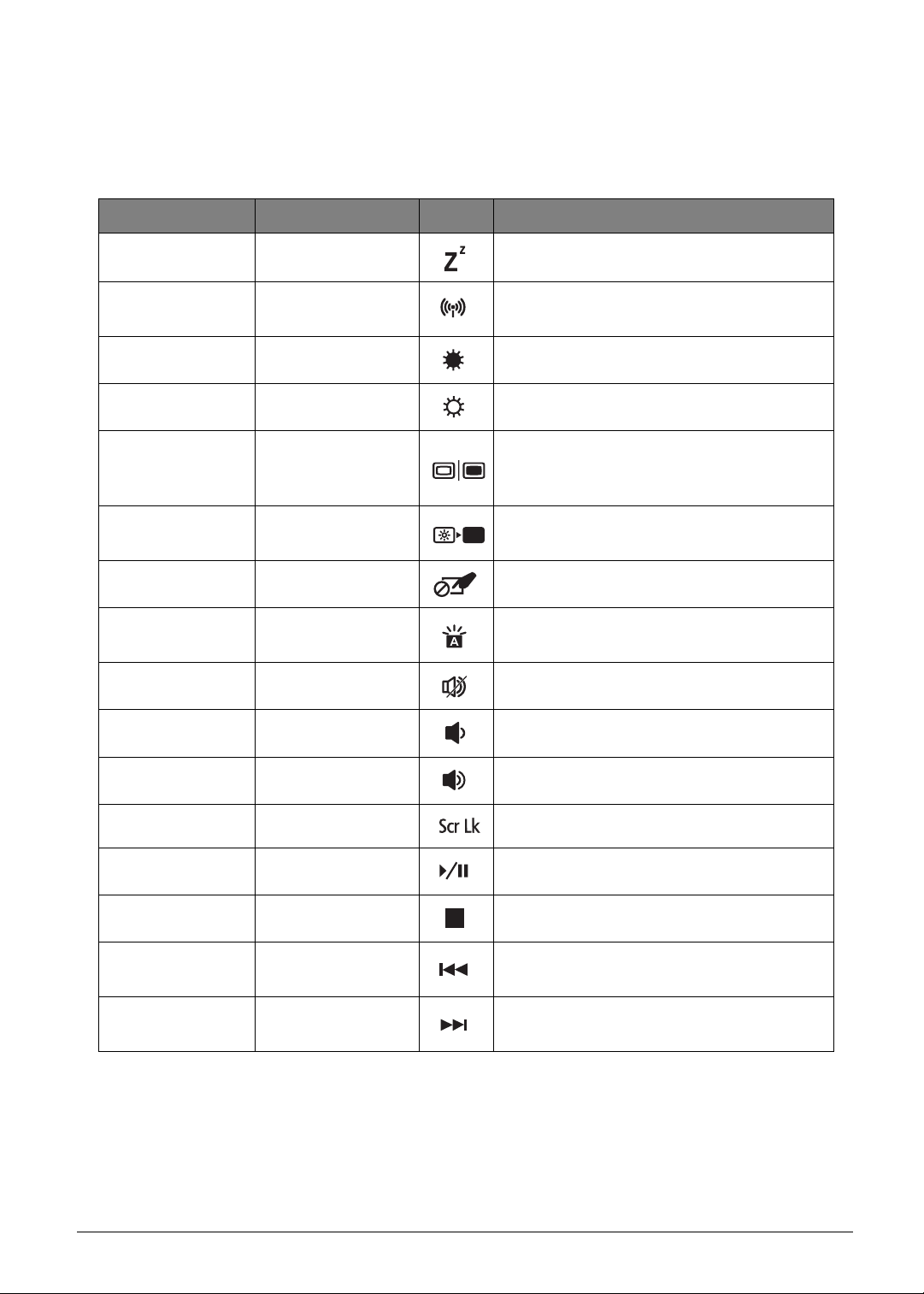
Table 1-9. Hotkey Combinations
Function Key Combination Icon Description
Sleep <F1> Puts the computer in Sleep mode.
Communication
Switch
Brightness Down <F3> Decreases screen brightness.
Brightness Up <F4> Increases screen brightness.
Display Toggle <F5>
Screen Blank <F6>
Touchpad Toggle <F7> Turns the touchpad on and off.
Keyboard
Backlight Toggle
Speaker Toggle <F9> Turns the speaker on or off.
Volume D own <F10> Decreases audio volume.
Volume Up <F11> Increases audio volume.
<F2>
<F8> Turns the keyboard backlight on or off.
Enables/disables wireless connectivity of
your computer.
Switches the display output between the
display screen, external monitor (if
connected), and both.
Turns the display screen backlight off to
save power. Press any key to return.
Scroll Lock <F12> Turns scroll lock on or off.
Play/Pause <Fn> + Up key Plays or pauses media file.
Stop <Fn> + Down key Stops media file.
Previous <Fn> + Left key
Next <Fn> + Right key
1-13 Hardware Specifications and Configurations
Plays the previous media file in the play
sequence.
Plays the next media file in the play
sequence.
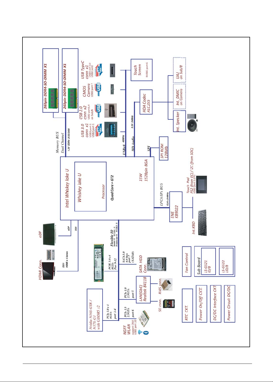
System Block Diagram
Figure 1-7. System Block Diagram
Hardware Specifications and Configurations 1-14
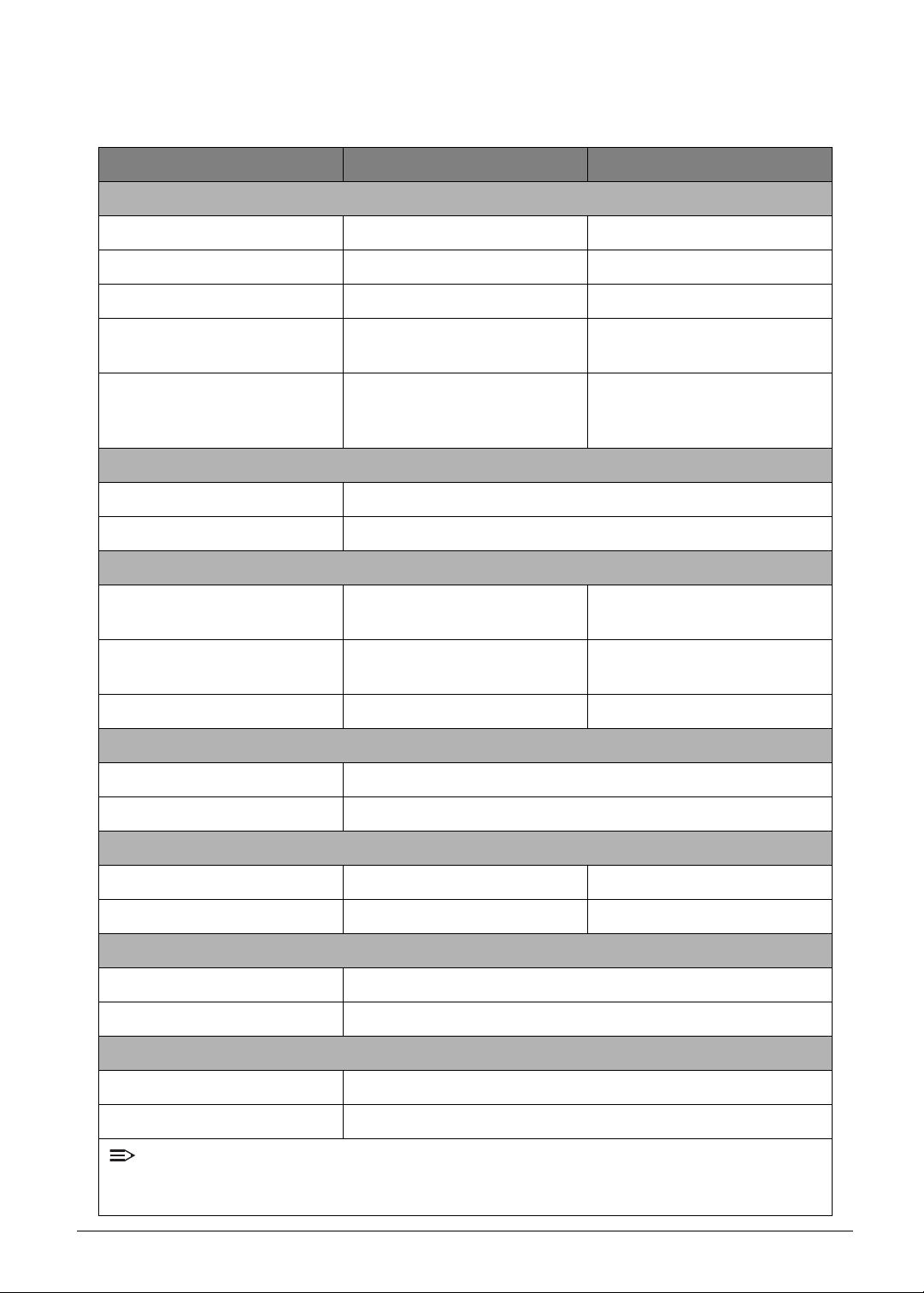
Specifications Table
Computer specifications
Item Metric Imperial
Dimensions
Length 363.4 mm 14.31 inches
Width 247.5 mm 9.74 inches
Height 18.85 mm 0.74 inch
Weight (equipped with optical
drive, flash drive, and battery)
Weight (equipped with optical
drive, flash drive, and without
battery)
Input power
Operating voltage 19V
Operating current 3.42A
Temperature
Operating (not writing to
optical disc)
Operating (writing to optical
disc)
Non-operating -20ºC ~ 60ºC -4º ~ 140ºF
Relative humidity
Operating 0%R.H ~ 80%R.H
Non-operating 0%R.H ~ 80%R.H
1.9 kg 4.2 lbs
N/A (Embedded Battery) N/A (Embedded Battery)
0ºC ~ 40ºC 32ºF ~ 104ºF
N/A N/A
Maximum altitude (unpressurized)
Operating N/A N/A
Non-operating N/A N/A
Shock
Operating Amplitude: 105G
Non-operating Amplitude: 220G
Random vibration
Operating 0.6 grms
Non-operating 1.5 grms
NOTE:
Applicable product safety standards specify thermal limits for plastic surfaces. The computer
operates well within this range of temperatures.
1-15 Hardware Specifications and Configurations
System Board Major Chips
Item Specification
Core logic
• INTEL Whiskey Lake Processor Family (U4+2, 15W)
• INTEL Whiskey Lake Processor Family (U2+2, 15W)
VGA Intel HD Graphics Family (GT2)
VGA (Discrete) NVIDIA N16S-GTR / N17S-G1
USB 2.0 X2
USB 3.0 X1
USB Type-C X1
Audio codec Realtek ALC255 codec
Amplifier Realtek ALC255 build-in class-D speaker amplifier
LAN/Card reader Realtek RTL8411B with SD card reader
EC ENE KB9022QD
Processor
Item Specification
CPU
• INTEL Whiskey Lake Processor Family (U4+2, 15W)
• INTEL Whiskey Lake Processor Family (U2+2, 15W)
CPU package BGA1528
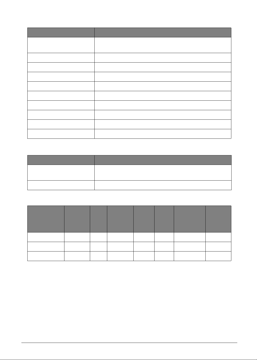
Processor Specifications
Bus
Speed
(FSB/DMI/
QBI)
Mfg
Tech
Cache
Size
Package Voltage
Item
CPU
Speed
(GHz)
Cores
I7-8565U 1.8G 4 N/A 14nm 8MB BGA1528 0-1.05V
I5-8265U 1.6G 4 N/A 14nm 6MB BGA1528 0-1.05V
I3-8145U 2.1G 2 N/A 14nm 4MB BGA1528 0-1.05V
Hardware Specifications and Configurations 1-16

System Memory
Item Specification
Memory controller INTEL Whiskey Lake platform
DIMM socket number X2 DDR4 socket
Supports memory size per
socket
Supports maximum memory
size
2G/4G/8G/16G
Total 32GB
Supports DIMM Speed DDR4 2133/2400
Support DIMM voltage 1.2V
Supports DIMM package 260-pin DDR4 SODIMM
1-17 Hardware Specifications and Configurations

Graphics Controller and VRAM
Item Specification
Graphics Controller
Chip
Intel Whiskey lake-U Processor (Intel integrate)
Package BGA1528
Interface Intel integrate
Memory
• 64MB (BIOS allocate)
• 128MB (WIN 10 Dedicated)
VRAM Chipset N/A
• The processor graphics is based on Gen 9 LP (generation 9 Low
Power) graphics core architecture that enables substantial gains in
performance and lower-power consumption over prior generations.
• Gen 9 LP architecture supports up to 48 Execution Units (EUs).
• Operating Systems Support
• Windows* 10 x64,OS X, Linux* OS, Chrome* OS
• API Support (Windows*)
• Direct3D* 2015, Direct3D 11.2, Direct3D 11.1, Direct3D 9, Direct3D 10,
Direct2D
• OpenGL* 4.5
• OpenCL* 2.1, OpenCL 2.0, OpenCL 1.2
• Hardware Accelerated Video Decode
• Direct3D* 9 Video API (DXVA2)
• Direct3D11 Video API
• Intel Media SDK
• MFT (Media Foundation Transform) filters
Supports
Supports full HW accelerated video decoding for AVC/VC1/ MPEG2/HEVC/
VP8/JPEG.
• Hardware Accelerated Video Encode
• Intel Media SDK
• MFT (Media Foundation Transform) filters
Supports full HW accelerated video encoding for AVC/ MPEG2/HEVC/VP8/
JPEG.
• Hardware Accelerated Video Processing
• Direct3D* 9 Video API (DXVA2)
• Direct3D 11 V ideo API
• Intel Media SDK
• MFT (Media Foundation Transform) filters
• Intel CUI SDK
• Hardware Accelerated Transcoding
• Low-power and low-latency AVC encoder for video conferencing and
Wireless Display applications.
• Lossless memory compression for media engine to reduce media power.
• HW assisted Advanced Video Scaler.
• Low power Scaler and Format Converter
Hardware Specifications and Configurations 1-18
Item Specification
Graphics Controller
Chip
NVIDIA N16S-GTR NVIDIA N17S-G1
Package FCBGA 595P FCBGA 595P
Interface Internal PCIE x4 Internal PCIE x4
Memory 2GB GDDR5 at 1.35V 2GB GDDR5 at 1.35V
VRAM Chipset Hy ni x/ Micron Hyni x/ Micron
• PCI Express 3.0 Interface
• NVIDIA Optimus technology
• DirectX* 11.2 support
• OpenGL* 4.4 or later support
• NVIDIA
®
PhysX®, CUDA™
Supports
• PCI Express 3.0 Interface
• NVIDIA Optimus technology
• DirectX* 11.2 support
• OpenGL* 4.4 or later support
• NVIDIA
®
PhysX®, CUDA™
BIOS
Item Specification
BIOS vendor Insyde
BIOS Version 1.01
BIOS ROM type SPI ROM
BIOS ROM size 16 MB
Features N/A
1-19 Hardware Specifications and Configurations

LAN Interface
Item Specification
LAN Chipset Realtek RTL8411B
LAN connector type RJ45
LAN connector location JRJ45 on the left side
• Hardware
• Integrated 10/100/1000M transceiver
• Auto-Negotiation with Next Page capability
• Supports PCI Express 1.1
• Supports 1-Lane 2.5Gbps PCI Express Bus
• Supports pair swap/polarity/skew correction
• Crossover Detection & Auto-Correction
• Wake-On-LAN support
• Embedded OTP memory can replace the external EEPROM
• Transmit/Receive on-chip buffer support
• Supports hardware ECC(Error Correction Code) function
• Supports hardware CRC(Cyclic Redundancy Check) function
• Customizable LEDs
• Controllable LED Blinking Frequency and Duty Cycle
• Built-in switching regular
• Built-in LDO regulator
Features
• Supports PCI MSI (Message Signaled Interrupt) and MSI-X
• Supports LTR(Latency Tolerance Reporting) and OBFF
(Optimized Buffer Flush/Fill)
• Supports 16-set 128-byte Wake-Up Frame patte rn ex-act
matching
• Supports Microsoft WPD (Wake Packet Detection)
• Supports PCIe L1.Off and L1.Snooze
• Embeds an adaptive equalizer in-PCI Express PHY (PCB
traces to reach up to 20cm)
• Supports power down/link down power saving/PHY disable
mode/LAN disable mode
• IEEE
• Fully complies with IEEE 802.3, IEEE 802.3u, IEEE 802.3ab
• Supports Full Duplex flow Control (IEEE 802.3x)
• Supports IEEE 802.IP Layer 2 Priority Encoding
• Supports IEEE 802.1Q VLAN tagging
• Supports IEEE 802.3az-2010 (EEE)
Hardware Specifications and Configurations 1-20

Keyboard
Item Specification
Type SV5P_A72BWL / SV5T_A72B
Total number of keypads 100-US / 101-UK, BR / 104-JP keys
Windows logo key Yes
Internal & external keyboard
work simultaneously
Features
Plug USB keyboard to the USB port directly: Yes
• Phantom key auto detect
• Support independent pgdn/pgup/home/end keys
• Support reverse T cursor keys
• Factory configurable different languages by OEM customer
1-21 Hardware Specifications and Configurations
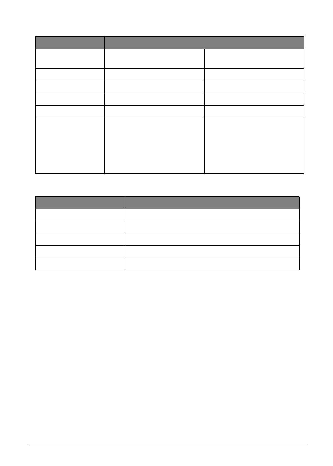
Hard Disk Drive (Listed items from AVL list)
Item Specification
Vendor and model
names
TOSHIBA
MQ01ABF050 F:AM002
WDC
WD5000LPCX-21VHAT0
TOSHIBA
MQ04ABF100
Capacity 500GB 500GB 1TB
Bytes per sector 4096 4096 4096
Data heads 2 2 2
Drive Format
Disks 1 1 1
Spindle s peed 5400RPM
Performance Specifications
Buffer size 8MB 16MB 128MB
Interface SATA 6Gb/s
Fast data transfer ra te
(Mbits/sec, max)
Media data transfer rate
135 MB/s 147 MB/s 135 MB/s
1469.7 Mb/s 147 MB/s 1733 MB/s
(Mbytes/sec max)
DC Power Requirements
Voltage tolerance 5V ±5%
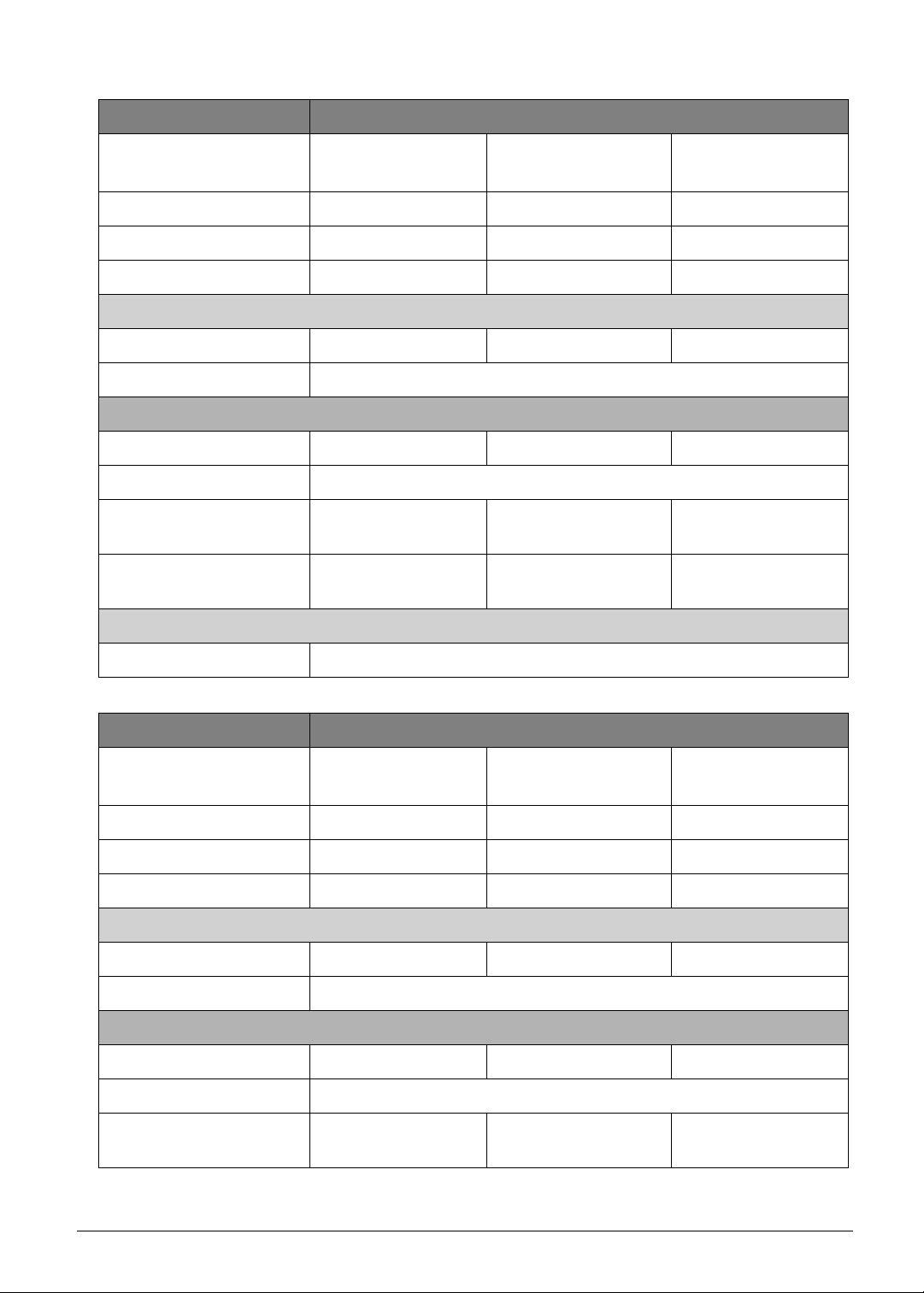
Item Specification
Vendor and model
names
WDC
WD10SPZX-21Z10T0
SEAGATE
ST1000LM035 F:ACM2
SEAGATE
ST2000LM007 F:ACM2
Capacity 1TB 1TB 2TB
Bytes per sector 4096 4096 4096
Data heads 2 2 4
Drive Format
Disks 1 1 2
Spindle s peed 5400RPM
Performance Specifications
Buffer size 128MB 128MB 128MB
Interface SATA 6Gb/s
Fast data transfer ra te
(Mbits/sec, max)
130 MB 140 MB 140 MB
Hardware Specifications and Configurations 1-22
Item Specification
Media data transfer rate
(Mbytes/sec max)
130 MB 140 MB 140 MB
DC Power Requirements
Voltage tolerance 5V ±5%
Solid-State Drive (Listed items from AVL list)
Item Specification
Vendor and
model names
SANDISK
SD9SN8W-128G-1014
HYNIX
HFS128G39TND-N210A
KINGSTON
RBU-SNS8180DS3/128GJ
Capacity (GB) 128 128 128
Performance Specifications
Interface SATA 6Gb/s
Fast data
transfer rate
(Mbits / sec,
560 MB 560 MB 535 MB
max)
DC Power Requirements
Voltage
tolerance
3.3V ±5%
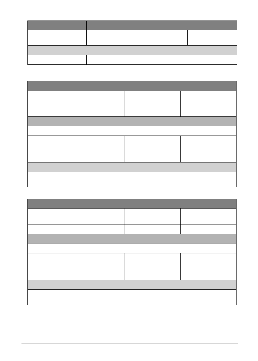
Item Specification
Vendor and
model names
SANDISK
SD9SN8W-256G-1014
HYNIX
HFS256G39TNH-72A0A
MTFDDA V 256TB N-1AR1ZA BYY
MICRON
Capacity (GB) 256 256 256
Performance Specifications
Interface SATA 6Gb/s
Fast data
transfer rate
(Mbits / sec,
560 MB 560 MB 530MB
max)
DC Power Requirements
Voltage
tolerance
3.3V ±5%
1-23 Hardware Specifications and Configurations
 Loading...