

Page 1

System Specification
Specification
Operating System
• MS-DOS (Minimal)
• Windows® XP SP2 Home / Professional
• Windows® XP Professional x 64 Edition
• Windows
• Windows® XP embeded
• Windows® VistaTM(Ultimate/Premium/Basic/Business)
• Microsoft Vista upgrade support
• Linux Suse v9.1 and Limpus v9.2 (Driver support
Platform
• Intel® Centrino® Duo mobile processor technology featuring:
• Intel® Core2 Duo mobile processor T7300/T7500/T7700 (4 MB L2 cache, 2/2.2 /2.4 GHz, 800 MHz
• Mobile Intel® PM965 Express Chipset
• Intel® Wireless WiFi Link 4965AGN (dual-band quad-mode 802.11a/b/g/Draft-N) network
• Intel® PRO/Wireless 3945ABG (dual-band tri-mode 802.11a/b/g) network connection Wi-Fi
®
XP Professional Media Center Edition
FSB), or T7100 (2 MB L2 cache, 1.8 GHz, 800 MHz), supporting Intel 64 architecture
connection, supporting Acer SignalUp with InviLink Nplify wireless technology, or
CERTIFIED® solution, supporting Acer SignalUp wireless technology
Chapter 1
System Memory
• DDR II 533/677 SDRAM memory interface design. 2 memory slots, 2GB maximum gmemory for one
Slotg. Total 4GB using two soDIMM modules
Display and Graphics
• 20.1"(1680X1050) WSXGA+ 300-nit Acer CrystalBriteTM high-brightness TFT LCD,16 ms(Typical on/off)/
5 ms(Average gregy-to-grey) response time
• Supporting simultaneous multi-window viewing via Acer GridVista
• NVIDIA® GeForce8600M GT/GS with up to 1024 MB of TurboCache technology (256/512 MB of
dedicated GDDR2 VRAM, up to 768 MB of shared system memory).
• Supporting NVIDIA® PureVideoTM technology (WMV HD, High-Definition MPEG-2 Hardware
Acceleration, Microsoft
technology and PCI Express
• Dual independent display
• 16.7 million colors
• MPEG-2/DVD hardware-assisted capability (acceleration)
• WMV9 (VC-1) and H.264 (AVC) support (acceleration)
• S-video/TV-out (NTSC/PAL) support
Chapter 1 1
T
TM
®
DirectX® 9.0 and DirectX® 10. OpenEXR Hight Dynamic Range (HDR)
Page 2

• DVI-D (ture digital video interface) with HDCP (High-bandwidth Digital Content Protection) support
• Acer ArcadeTM featuring Acer CinemaVisionTM and Acer ClearVision technologies
Audio
• Dolby®-certified surround sound system with two built-in stereo speakers and one subwoofer
supporting low-frequency effects
• Dolby® Home Theater audio enhancement featuring Dolby® Digital, Dolby® Digital Live, Dolby®
PRO LOGIC® II, Dolby® Digital Stereo Creator, Dolby® Headphone and Dolby® Virtual Speaker
technologies
• Intel® High Definition Audio support
• S/PDIF (Sony/Philips Digital Interface) support for dig ital speakers
• MS-Sound compatible
• Acer PureZone technology with two built-in stereo microphones featuring beam forming, echo
cancellation, and noise suppression technologies
Storage Subsystemg
• One or two 80/120/160/240/250 GB or larger hard disk drives
• Intel® Turbo Memory supported (for selected models)
• Optical drive options: HD-DVD, DVD-Super Multi double-layer drive, DVD/CD-RW combo drive.
• 5-in-1 card reader, supporting Secure Digital (SD), MultiMediaCard (MMC), Memory Stick (MS),
Memory Stick PRO (MS PRO), xD-Picture Card (xD)
Communication
• Acer Video Conference, featuring:
• Integrated Acer Crystal Eye webcam, supporting Acer PrimaLite technology
• Acer PureZone technology
• Optional Acer Xpress VoIP phone
• WLAN: Intel® Wireless WiFi Link 4965AGN (dual-band quad-mode 802.11a/b/g/Draft-N) network
connection, supporting Acer SignalUp with InviLink Nplify wireless technology or Intel PRO/Wireless
3945ABG (dual-band tri-mode 802.11a/b/g) Wi-Fi CERTIFIED network connection, supporting Acer
SignalUp wireless technology
• WPAN: Bluetooth® 2.0+EDR (Enhanced Data Rate)
• LAN: Gigabit Ethernet; Wake-on-LAN ready
• Modem: 56K ITU V.92 with PTT approval; Wake-on-Ring ready
Input Devices
• Darfon 17 KB - FV2-New Aspire gcommom K/B
• 12 function keys, four cursor keys, two Windows
international language support
• Touch pad with 4-way scroll button
• Five easy-launch buttons: Empowgering Key, email, Internet, Hibernation and user-programmable button
• Two communication LED switches: WLAN and Bluetooth
®
keys, hotkey controls, embedded numeric keypad,
®
I/O Interface
• VGA port, 15 pins
2 Chapter 1
Page 3

• Microphone-in jack
• Line-in jack
• Headphones/Speaker/line-out port with S/PDIF support
• S-Video port/TV-out (NTSC/PAL) port
• A V-in port
• TV-tuner antenna-in port
• External USB 2.0 connectors x 4
• DC in jack
• RJ-11 jack for Modem
• RJ-45 jack for LAN
• IEEE 1394a x1(4-pin)
• PCMCIA slot
• PCI-Express Card
• Consumer infrared (CIR) port
• Parallel port
• Serial port
• DVI-D
• CMOS Camera
• 5-in-1 card reader (SD/MMC/MS/MS PRO/xD)
Power Subsystem
• ACPI 2.0 CPU power management standards: Stand-by and Hibernation power-saving modes support
• 71W 4800mAh 8-cell Li-Ion battery pack
• Acer 2QuicCharge
• 80% charge in 1 hour
• 2-hour rapid charge system-off
• 2.5-hggour charge-in-useg
• 3-pin 135 W AC adapter
TM
technology:
Security
• Kensington lock slot
• BIOS user and supervisor passwords
Dimensions and Weight
• 490 (W) X 380 (D) X 60 (H) mm (19.3 x 14.9 x 2.4 inches)
• 7.8kg with TV-tuner/2nd HDD/20.1” LCM
Environment
• Temperature:g
• Operating: 5
• Ng2on-operating: -20 oC to 65 oC
• Humidity (non-condensing):
• Operating: 20% to 80%
• Non-operating: 20% to 80%
Warning!
Chapter 1 3
For safety reasons, do not use non-compliant parts when you add or change components.
o
gC to 35 oC
Page 4
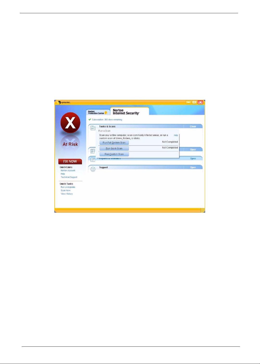
Norton Internet Security
Norton Internet Security is an anti-virus utility that can protect against viruses, keeping your
data safe and secure
How do I check for viruses?
1. Double-click the Norton Internet Security icon on the Windows desktop.
2. 2Select Tasks & Scans.
3. Select Run Scan to scan your system.
4. When the scan is complete, review the results of the scan.
Y ou can schegdule customized virus scans that tun unattended on specific dates and times or at periodic intervals.
If you are using gthe computer when the scheduled scan begins, it runs in the background so that you do not have
to stop working.
For more information, please refer to the Norton Internet Security help files.
4 Chapter 1
Page 5
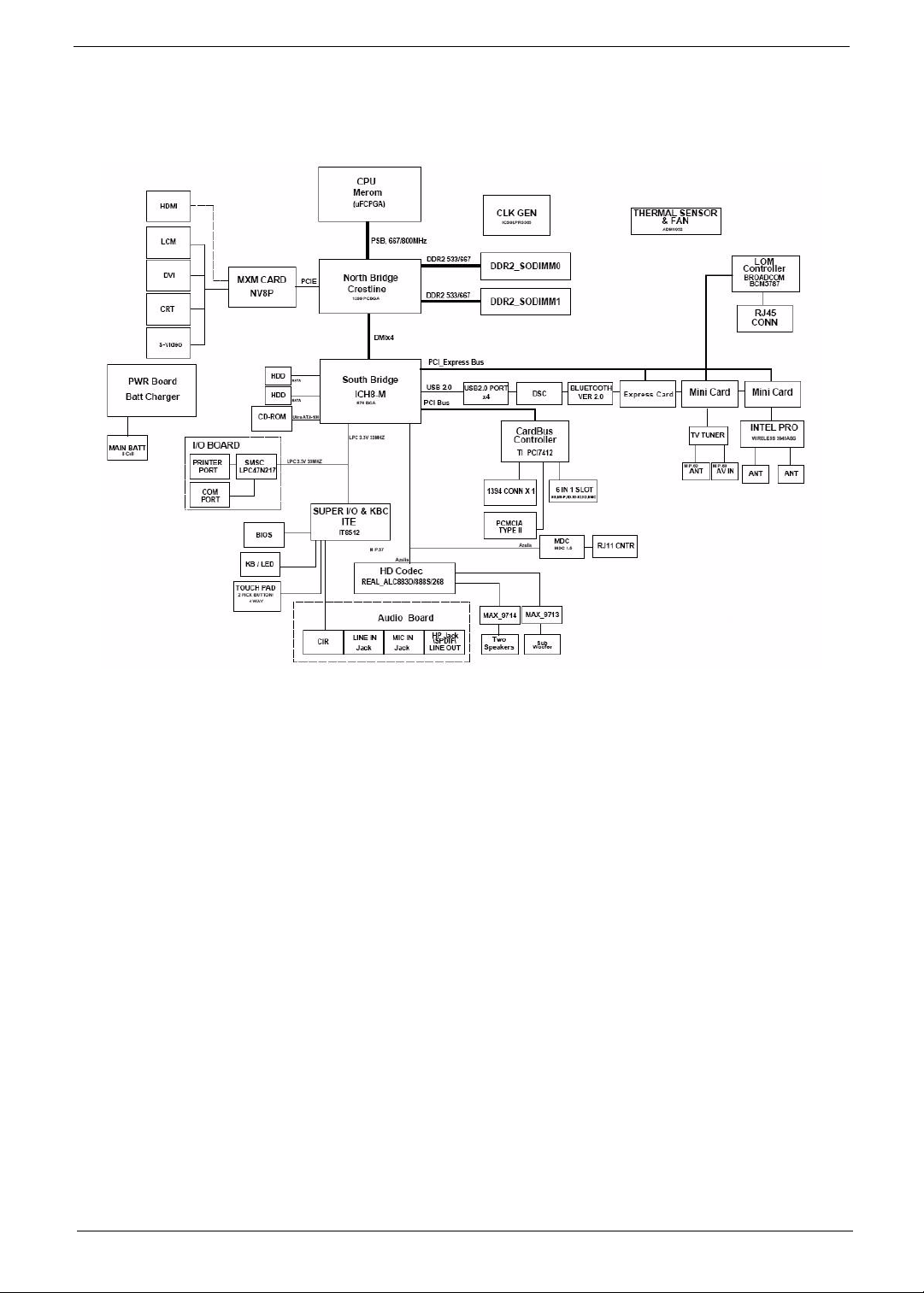
Block Diagram
Chapter 1 5
Page 6
Outlook Tour
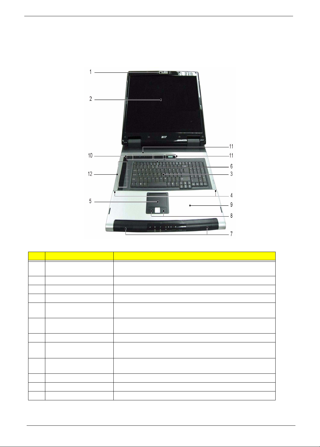
Front View
g
# Item Description
1 Acer Orbicam 1.3 megapixel web camera for video communication. (for selected
models)
2 Display screen Also called Liquid-Crystal Display (LCD), displays computer output.
3 Keyboard Serves to enter data into the computer.
4 Microphone Internal microphone for sound recording.
5 Touch pad Touch-sensitive pointing device which functions like a computer
mouse.
6 Status indicators Light-Emitting Diodes (LEDs) that light up to show the status of the
computer’s functions and components.
7 3D sonic speakers Left and right speakers deliver stereo audio output.
8 Click buttons
(left, center and right)
9 Palmrest Comfortable support area for your hands when you use the
10 Power button Turns the computer on and off.
11 Easy-launch buttons Buttons for launching frequently used programs
12 Media/volume buttons For use with Acer Arcade and other media playing programs.
The left and right buttons work like the left and right mouse buttons;
the center button serves as a four-way scroll button.
computer.
6 Chapter 1
Page 7
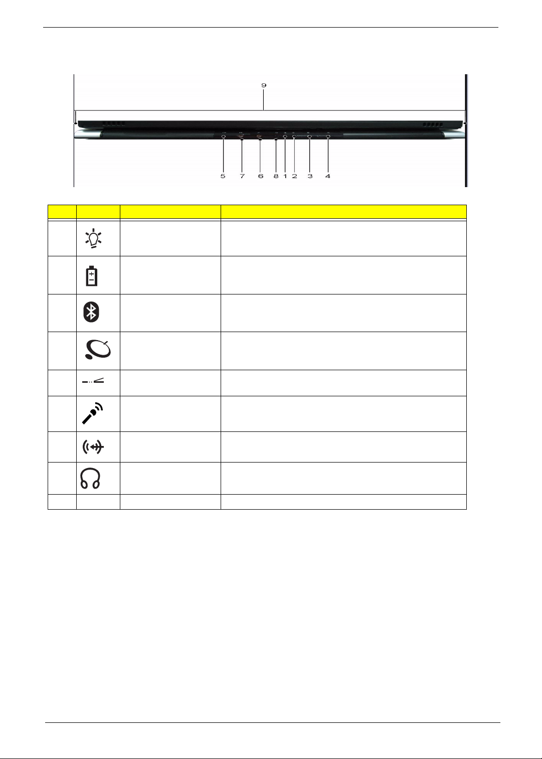
Closed Front View
# Icon Item Description
1 Power indicator Indicates the computer’s power status.
2 Battery indicator Indicates the computer’s battery status.
3 Bluetooth
communication button/
indicator
4Wireless
communication button/
indicator
5 Infrared port Interfaces with infrared devices (e.g., infrared printer and IR-
6 Microphone-in jack Accepts input from external microphones.
7 Line-in jack Accepts audio line-in devices (e.g., audio CD player, stereo
8 Headphones/speaker/
line-out jack
9 N/A Latch Locks and releases the lid.
Enables/disables the Bluetooth communicatio n. Indicates
the status of Bluetooth communication.
Enables/disables the wireless function. Indicates the status
of wireless LAN communication.
aware computer).
walkman).
Connects to audio line-out devices (e.g., speakers,
headphones).
Chapter 1 7
Page 8
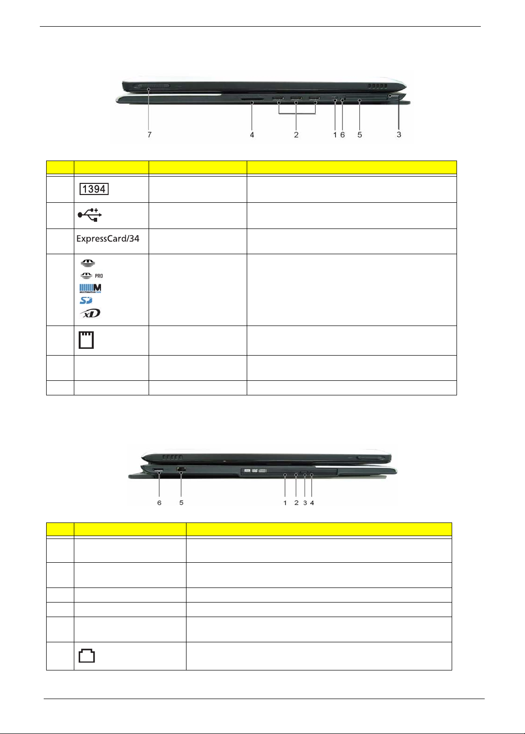
Left View
# Icon Item Description
1 4-pin IEEE 1394 port Connects to IEEE 1394 devices. (for selected
models)
2 Two USB 2.0 ports Connect to USB 2.0 devices (e.g., USB mouse, USB
camera). (3 total)
3 ExpressCard/34 slot Accepts one ExpressCard module. (for selected
models)
4 5-in-1 card reader Accepts Memory Stick (MS), Memory Stick Pro (MS
PRO), Multi Media Card (MMC), Secure Digital (SD)
and xD-Picture Card (xD). (for selected models)
5 PC Card slot Accepts one Type II PC Card.
6 N/A PC Card slot eject
button
7 N/A Latch Locks and releases the lid.
Ejects the PC Card from the slot.
Right View
g
# Item Description
1 Acer Media Bay optical
drive
2 Optical disk access
indicator
3 Optical drive eject button Ejects the optical disk from the drive.
4 Emergency eject hole Ejects the optical drive tray when the computer is turned off.
5 USB 2.0 port Connects to USB 2.0 devices (e.g., USB mouse, USB camera). (3
6
Modem (RJ-1 1) port
Internal optical drive; accepts CDs or DVDs.
Lights up when the optical drive is active.
total)
Connects to a phone line.
8 Chapter 1
Page 9
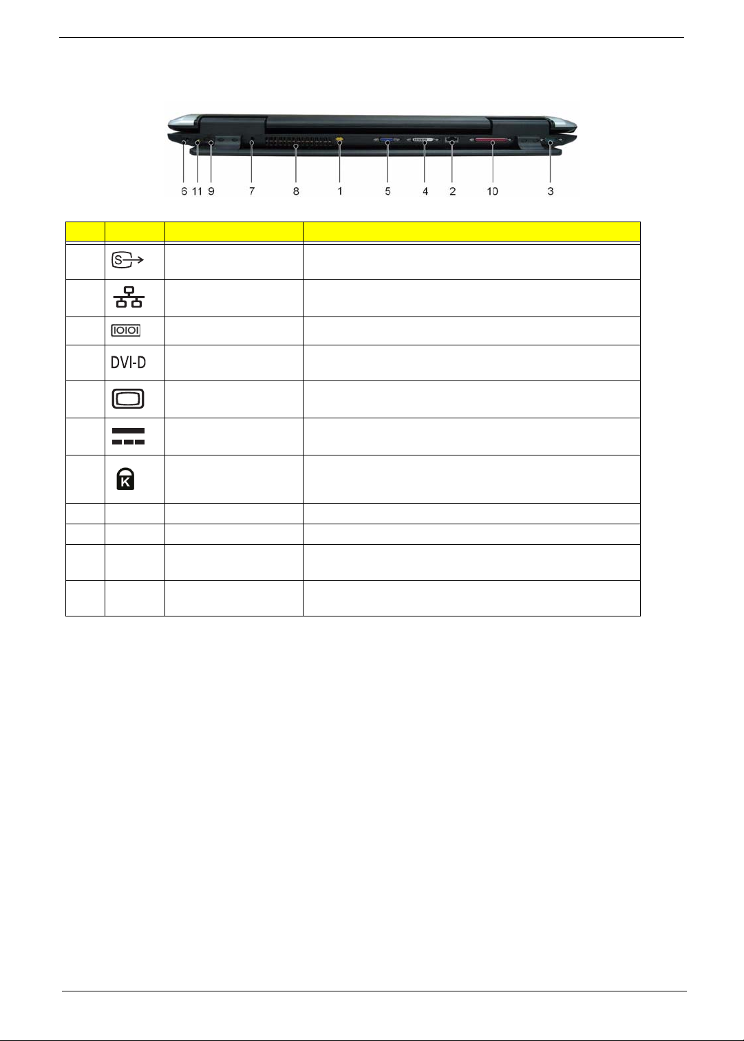
Rear View
# Icon Item Description
1 S-video port/TV out
port (NTSC/PAL) port
2 Ethernet (RJ-45) port Connects to an Ethernet 10/100/1000-based networks.
3 Serial port Connects to serial devices.
Connects to a television or display device with S-video
input. (for selected models)
4 Digital Video Interface -
Digital port
5 External display (VGA)
port
6 DC-in jack Connects to an AC adapter.
7 Kensington lock slot Connects to a Kensington-compatible computers security
8 N/A Ventilation slots Enable the computer to stay cool, even after prolonged use.
9 N/A Parallel port Connects to parallel devices.
10 N/A TV-in port Accepts input signals from analog/digital TVtuner devices
11 N/A AV-in port Accepts input signals from audio/video (AV) devices
Supports digital video connections. (for selected models)
Connects to an external display device (e.g., external
monitor, LCD projector).
lock.
(for selected models)
(manufacturing option)
Chapter 1 9
Page 10
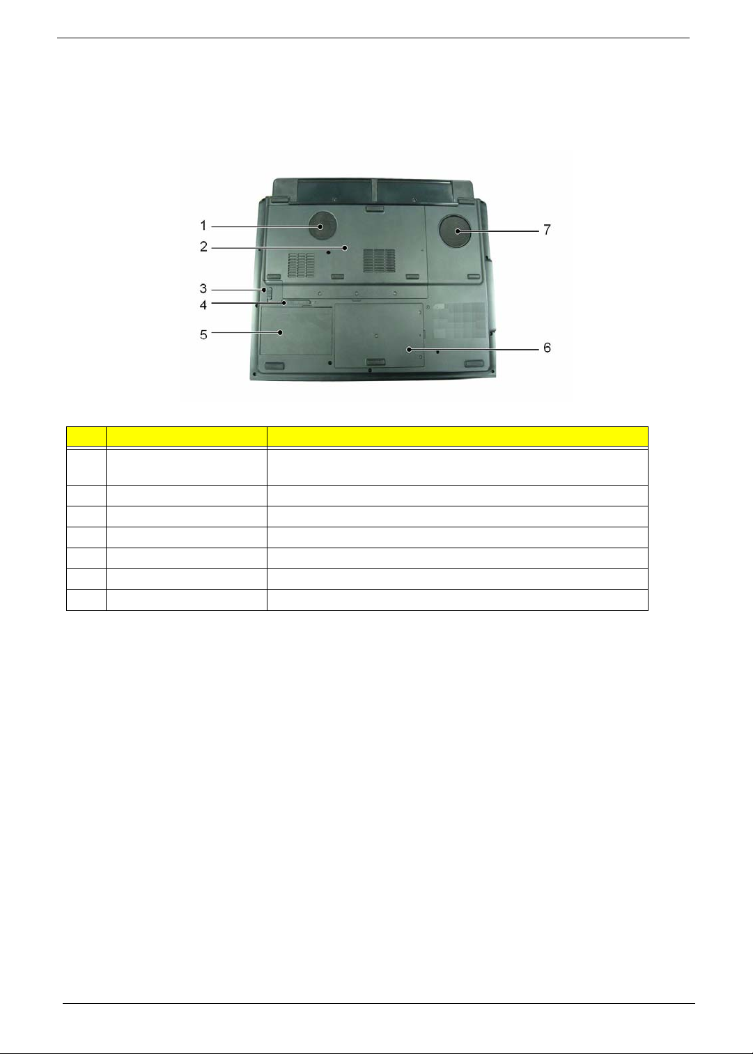
Base View
# Item Description
1 Ventilation slots and
cooling fan
2 Memory compartment Houses the computer’s main memory
3 Battery lock Locks the battery in position.
4 Battery latch Releases the battery for removal.
5 Battery bay Houses the computer’s battery pack.
6 Hard disk bay Houses the computer’s hard disk (secured with screws).
7 Sub woofer Emits low frequency sound output.
Ebable the computer to stay cool, even after prolonged use.
Note: Do not cover or obstruct the opening of the fan
10 Chapter 1
Page 11
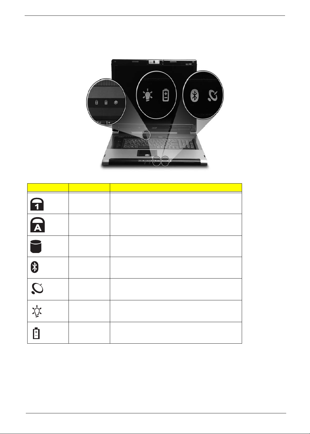
Indicators
The computer has eight several easy-to-read status indicators, including five on the front panel. The power, battery
and wireless communication status indicators are visible even when the LCD display is closed.
Icon Item Description
Num Lock Lights up when Num Lock is activated.
Caps Lock Lights up when Caps Lo ck is activated.
HDD Indicates when the hard disk drive is active.
Bluetooth Indicates the status of Bluetooth communication
Wireless LAN Indicates the status of wireless LAN communication
Power Lights when the computer is on.
Battery Lights when the battery is being charged.
Note: The light shows amber when the battery is charging. The light shows green when the system is under
AC mode.
Chapter 1 11
Page 12
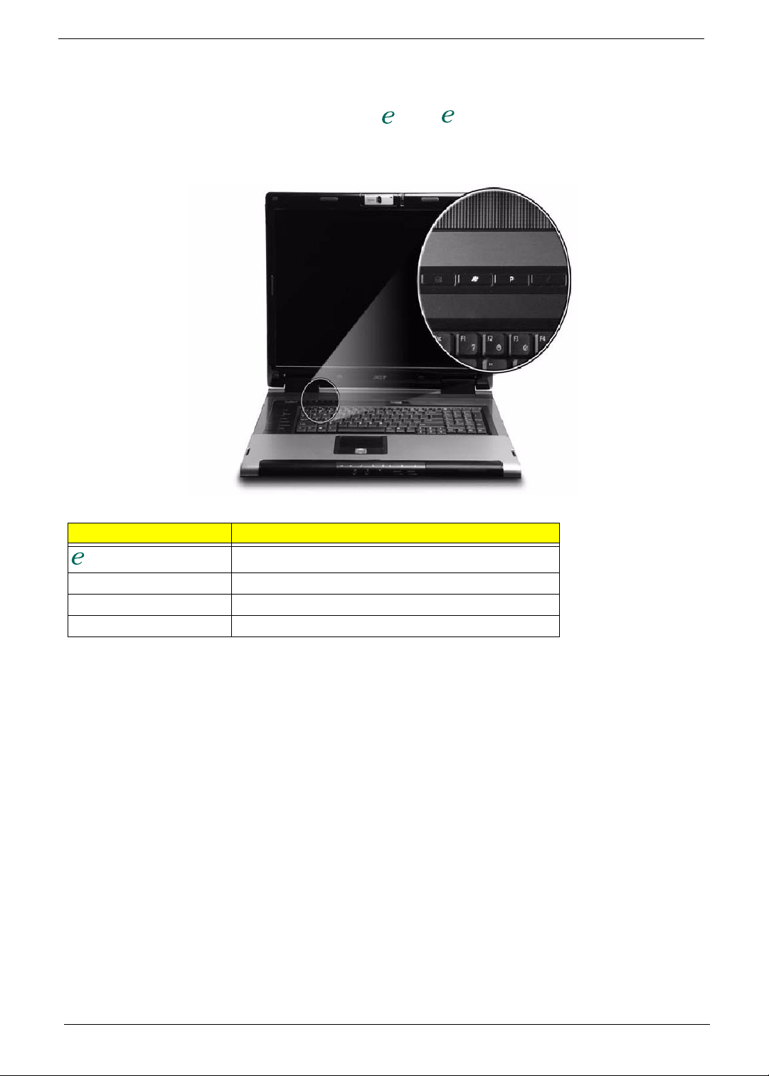
Easy-launch Buttons
There are several conveniently located easy-launch buttons. They are one user-programmable button, web
browser button, mail button, and Acer Empowering Key . Press to run the Acer Empowering Technology.
Although the mail and web browser buttons are pre-set to E-mail and Internet programs, they can be redefined by
users. To set the web browser, mail and programmable buttons, run the Acer Launch Manager.
Easy-launch button Default application
Acer Empowering Technology (user-programmable)
Mail E-mail application (user-programmable)
Web browser Internet browser (user-programmable)
P User-programmable
12 Chapter 1
Page 13
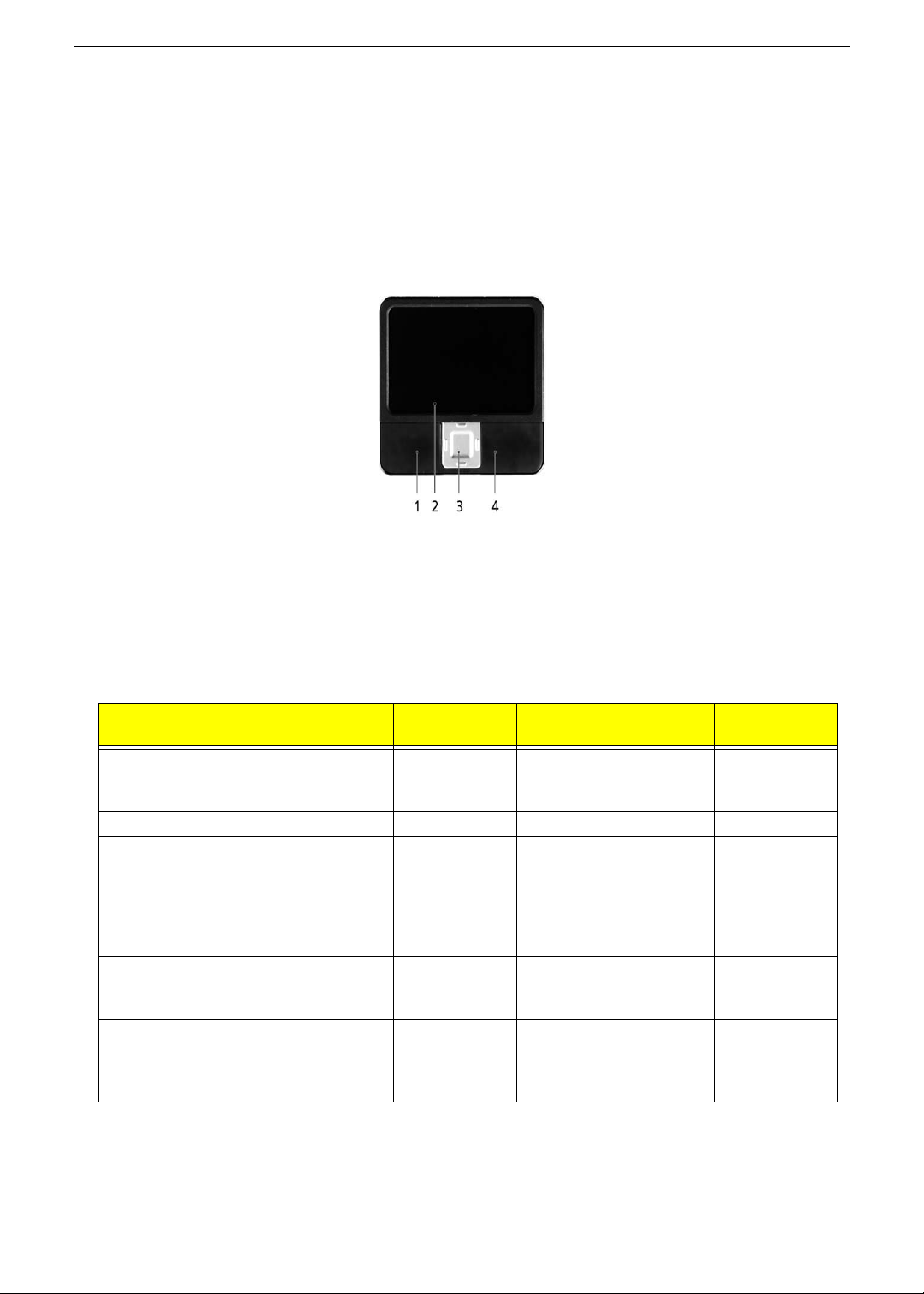
Touchpad
The built-in touchpad is a pointing device that senses movement on its surface. This means the cursor responds
as you move your finger across the surface of the touchpad. The central location on the palmrest provides
optimumg comfort and support.
Touchpad Basics
The following items will show you how to use the touchpad.
• Move your finger across the touchpad (2) to move the cursor.
• Press the left (1) and right (4) buttons to perform selection and execution functions. These two buttons are
similar to the left and right buttons on a mouse. Tapping on the touchpad is the same as clicking the left
button.
• Use the 4-way scroll (3) button to scroll up or down and move left or right a page. This button mimics the
cursor pressing on the right scroll bar of Windows applications.
Function Left button (1)
Execute Quickly click twice. Tap twice (at the same
Select Click once Tap once.
Drag Click and hold, then use
finger on the touchpad to
drag the cursor.
Access
context
menu
Scroll Click and hold
Note: Keep your fingers, as well as the surface of the touchpad dry and clean. The touchpad is sensitive to
your finger movement; hence, the lighter the touch, the better the response. Tapping hard will not increase the
touchpad’s responsiveness.
Note: By default, vertical and horizontal scrolling is enabled on your touch pad. It can be disabled under
Right button
(4)
Click once.
Main touchpad (2)
speed as double-clicking
a mouse button).
Tap twice (at the same
speed as double-clicking
a mouse button); rest
your finger on the
touchpad on the second
tap and drag the cursor.
Center
button (3)
to move up/
down/left/
right.
Chapter 1 13
Page 14

Mouse settings in Windows Control Panel.
14 Chapter 1
Page 15
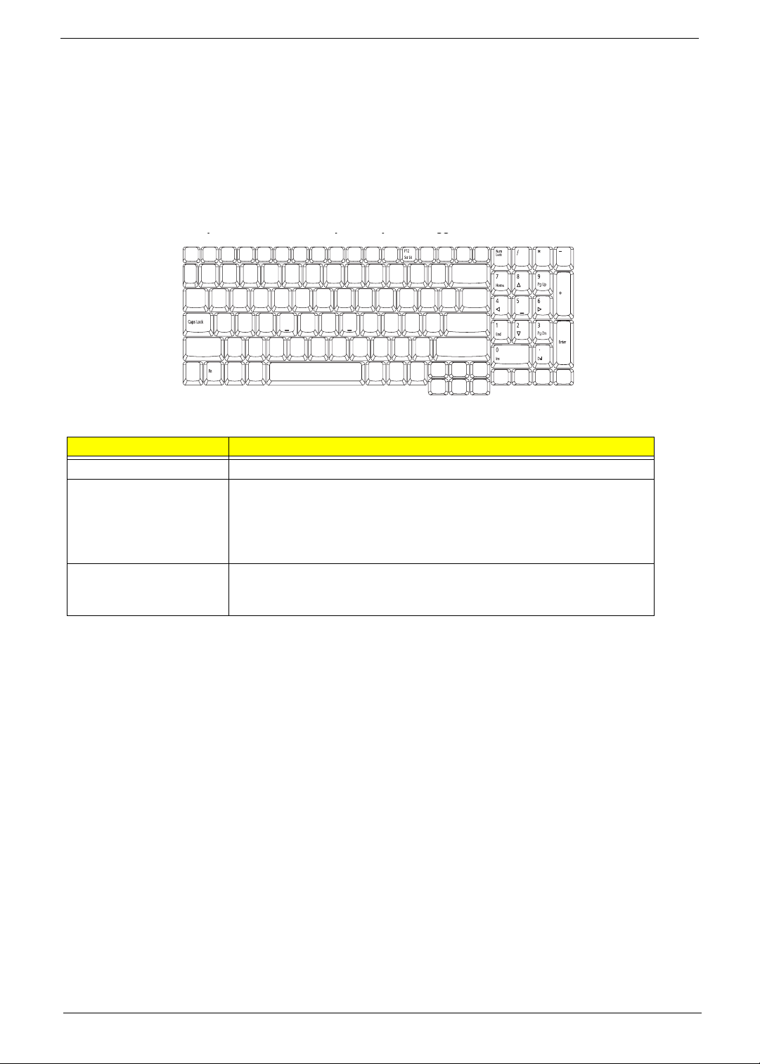
Using the Keyboard
yyygg
The full-sized keyboard includes an embedded numeric keypad, separate cursor, lock, Windows, function and
special keys.
Lock Keys and Embedded Numeric Keypad
The keyboard has three lock keys which you can toggle on and off.
Lock Key Description
Caps Lock When Caps Lock is on, all alphabetic characters are typed in uppercase.
Num Lock
<Fn> + <F11>
Scroll Lock
<Fn> + <F12>
When Num Lock is on, the separate keypad is in numeric
mode. The keys function as a calculator (complete with the
arithmetic operators +, -, *, and /). Use this mode when you
need to do a lot of numeric data entry.
When Scroll Lock is on, the screen moves one line up or down when you
press the up or down arrow keys respectively. scroll Lock does not work
with some applications.
Windows keys
The keyboard has two keys that perform Windows-specific functions.
Chapter 1 15
Page 16
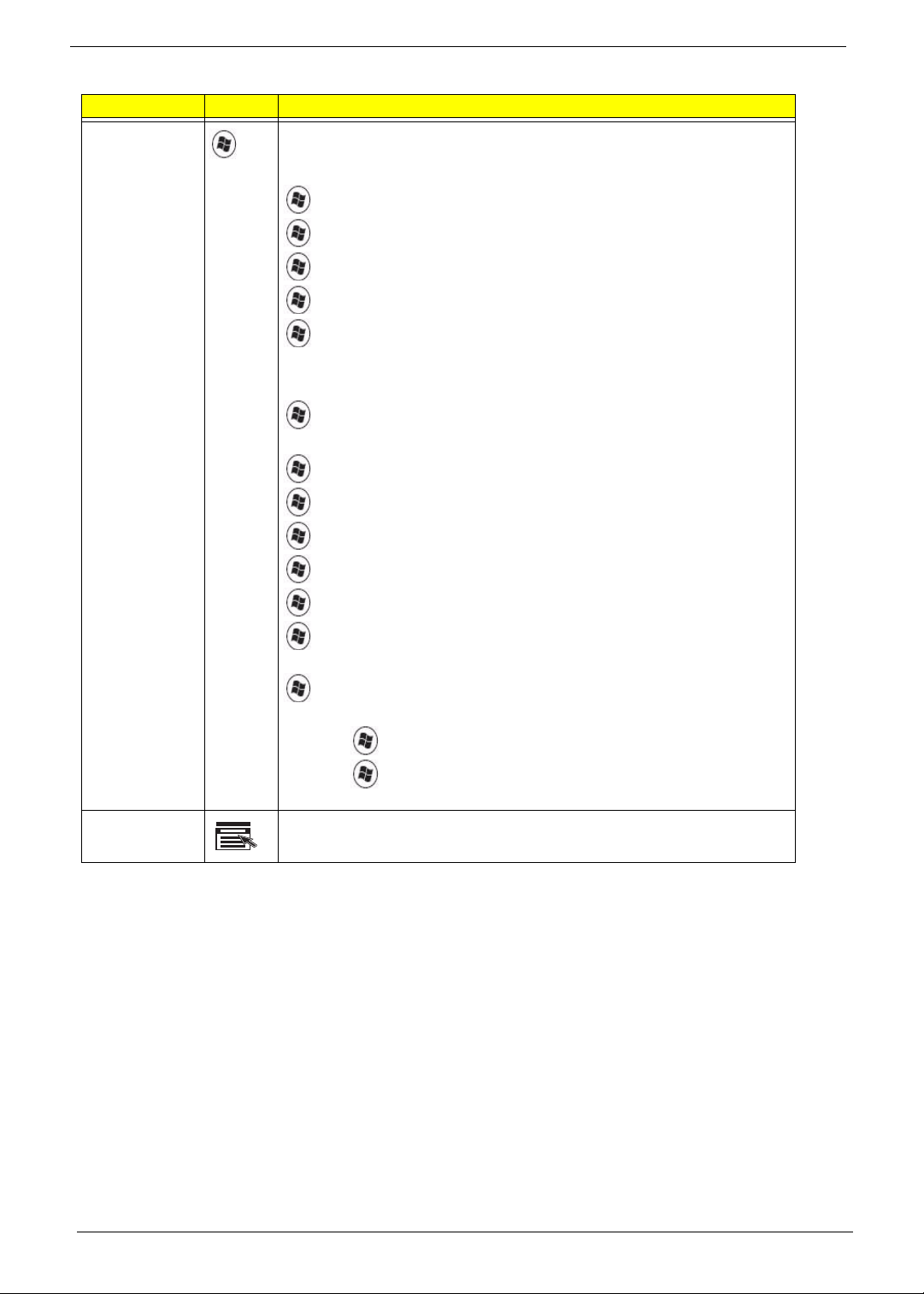
Key Icon Description
Windows key Press alone. This key has the same effect as clicking on the Windows Start
button. It launches the Start menu. It can also be used with other keys to
provide a variety of functions:
+ <D>: Display the desktop.
+ <E>: Opens Windows Exploer.
+ <F>: Opens the Find (All Files dialog box).
+ <G>: Cycle through Sidebar gadgets.
+ <L>:
Lock your computer (if you are connected to a
network domain), or switch users (if you're not connected to a
network domain) .
+ <M>: Minimizes all windows.
+ <R>: Open the Run dialog box.
+ <T>: Cycle through program on the taskbar.
+ <U>: Open Ease of Access Center.
+ <X>: Open Windows Mobility Center
+ <BREAK>: Display the System Properties dialog box.
+ <SHIFT+M>: Restore minimized windows to the desktop.
+ <TAB>: Cycle through programs on the taskbar by using Windows
Flip 3-D.
+ <SPACEBAR>: Bring all gadgets to the front and select Windows
Sidebar.
<CTRL>+ + <F>: Search for computers (if you are on a network).
<CTRL>+ + <TAB>: Use the arrow keys to cycle through program on
the taskbar by using Windows Flip 3-D .
Application key This key has the same effect as clicking the right mouse button. It opens
the application’s context menu.
Hotkeys
The computer employs hotkeys or key combinations to access most of the computer's controls like screen
brightness, volume output and the BIOS utility. To activate hotkeys, press and hold the <Fn> key before pressing
the other key in the hotkey combination.
16 Chapter 1
Page 17
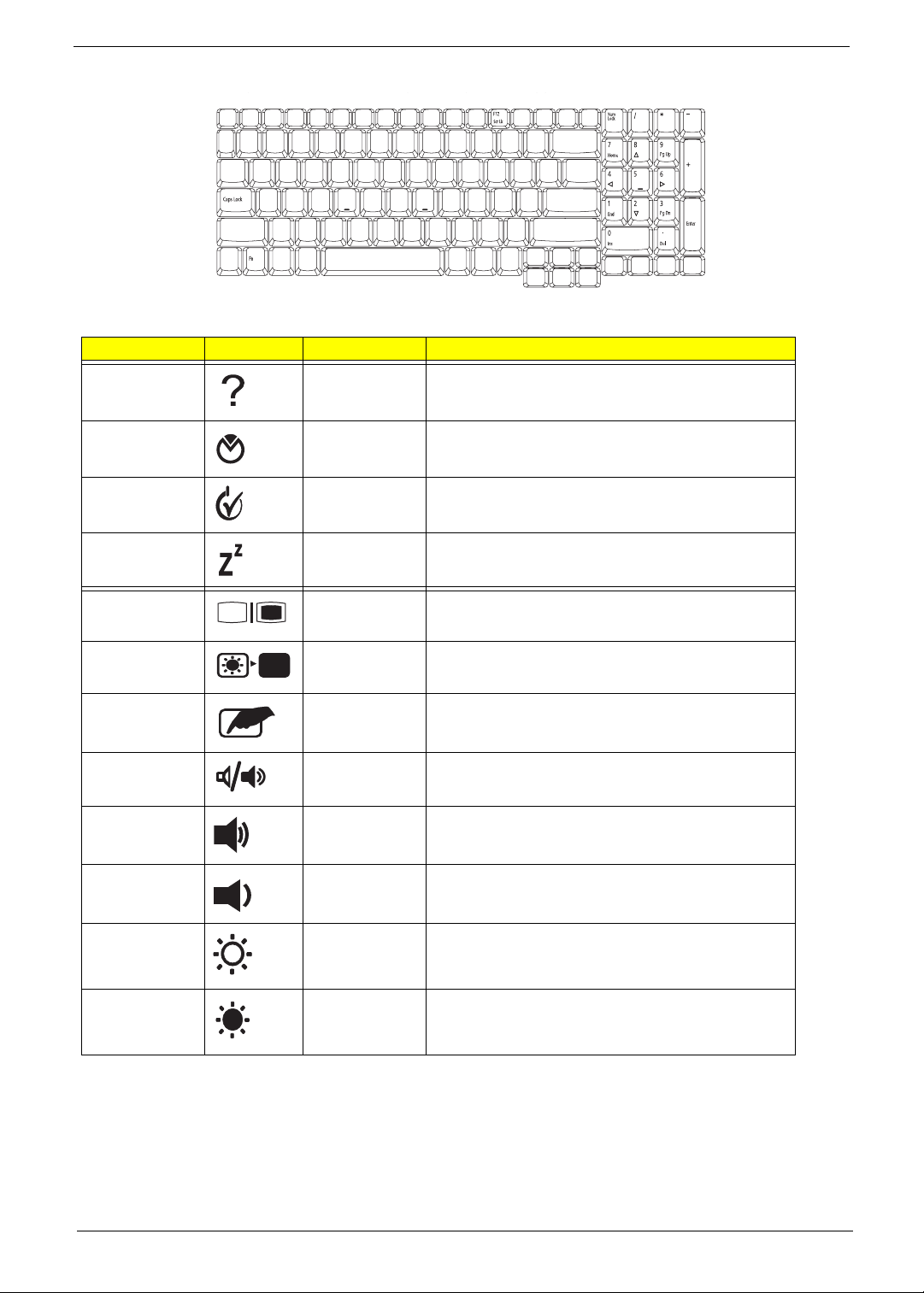
Hot Key Icon Function Description
yyygg
<Fn> + <F1> Hot key help Displays help on hotkeys.
<Fn> + <F2> Acer eSettings Launches the Acer eSettings in Acer Empowering
Technology.
<Fn> + <F3> Acer ePower
Management
<Fn> + <F4> Sleep Leads the computer to Sleep mode.
<Fn> + <F5> Display toggle Switches the display output between the display
<Fn> + <F6> Screen blank T urns off the display screen backlight to save power .
<Fn> + <F7> Touchpad
toggle
<Fn> + <F8> Speaker toggle Turns the speakers on and off.
<Fn> + <K> Volume up Increases the sound volume.
<Fn> + <L> Volume down Decreases the sound volume.
<Fn> + <J> Brightness up Increases the screen brightness.
Launches the Acer ePower Management in Acer
Empowering Technology.
screen, external monitor (if connected) and both.
Press any key to return.
Turns the internal touchpad on and off.
<Fn> + <I> Brightness
down
Decreases the screen brightness.
Special keys
You can locate the Euro symbol and US dollar sign at the upper-center and/or bottom-right of your keyboard.
Chapter 1 17
Page 18

The Euro symbol
yyygg
1. Open a text editor or word processor.
2. Either directly press the <> symbol at the bottom-right of the keyboard, or hold <Alt Gr> and then
press the<5> symbol at the upper-center of the keyboard.
NOTE: Some fonts and software do not support the Euro symbol. Please refer to www.microsoft.com/
typography/faq/faq12.htm for more information.
The US dollar sign
1. Open a text editor or word processor.
2. Either directly press the <> key at the bottom-right of the keyboard, or hold <Shift> and then press the
<4> key at the upper-center of the keyboard.
Note: This function varies by the operating system version.
18 Chapter 1
Page 19

Acer OrbiCam
The Acer OrbiCam is a 1.3 megapixel CMOS camera appropriately mounted on top of the LCD panel. The
camera’s 225-degree ergonomic rotation allows you to capture high-resolution photos or videos up front or at the
back of the LCD panel. The Acer OrbiCam fully supports the Acer Video Conference technology so you transmit
the best video conference quality over an instant messenger service.
# Item
1 Lens
2 Power indicator
Rotating the Acer OrbiCam
The Acer OrbiCam rotates 225 degrees counterclockwise to achieve the desired angle. Refer to the illustrations
below:
Note: Do NOT rotate the camera clockwise to prevent damage to the device.
For your convenience, the camera snaps 45 degrees to match the position of your face in front or at the back of
the LCD panel.
Chapter 1 19
Page 20
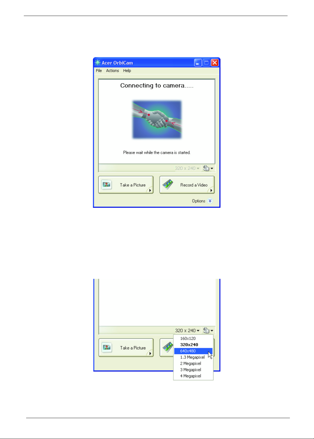
Launching the Acer OrbiCam
To launch the Acer OrbiCam, double-click on the Acer OrbiCam icon on the desktop, or click Start > All Programs
> Acer > Acer OrbiCam. The Acer OrbiCam capture window will appear as below.
Changing the Acer OrbiCam Settings
Resolution
To change the capture resolution, click the displayed resolution at the bottom right corner of the capture window,
then select the desired resolution.
Note: Setting the camera resolution to 640 x 480 or larger does not change the capture window size.
20 Chapter 1
Page 21
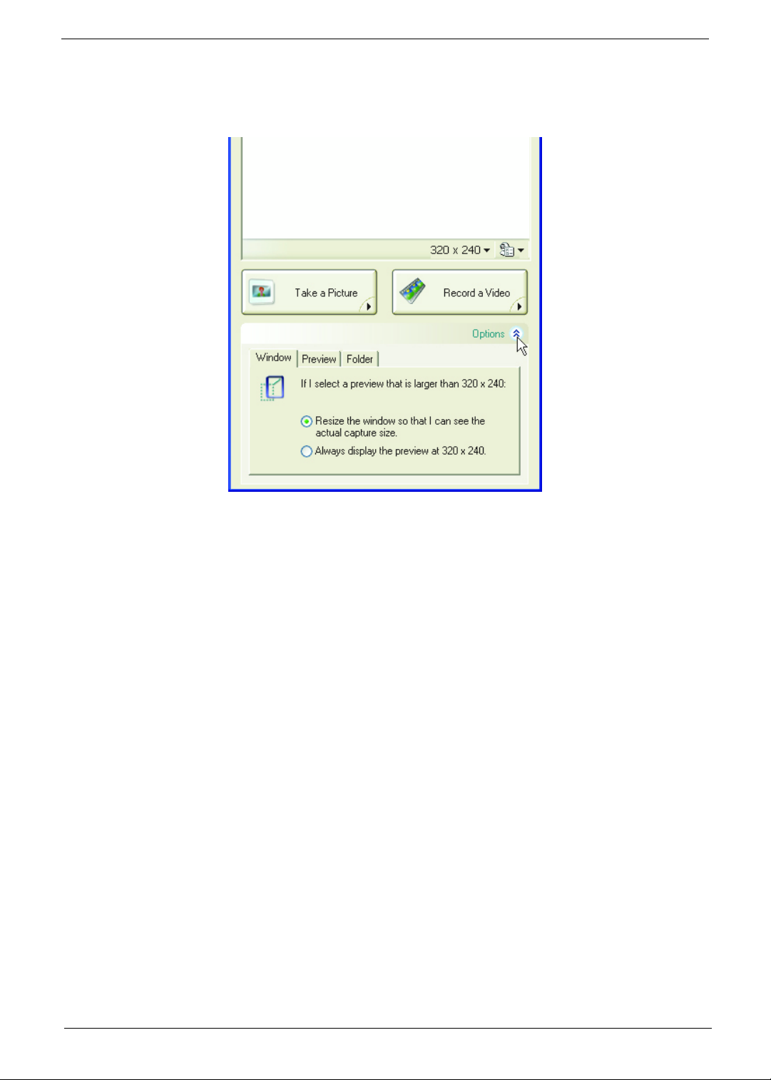
Options
Click Options to display the Window, Preview, and Folder tabs. Use the options to change the capture window
size, preview settings, and the folder for captured photos or videos.
Chapter 1 21
Page 22
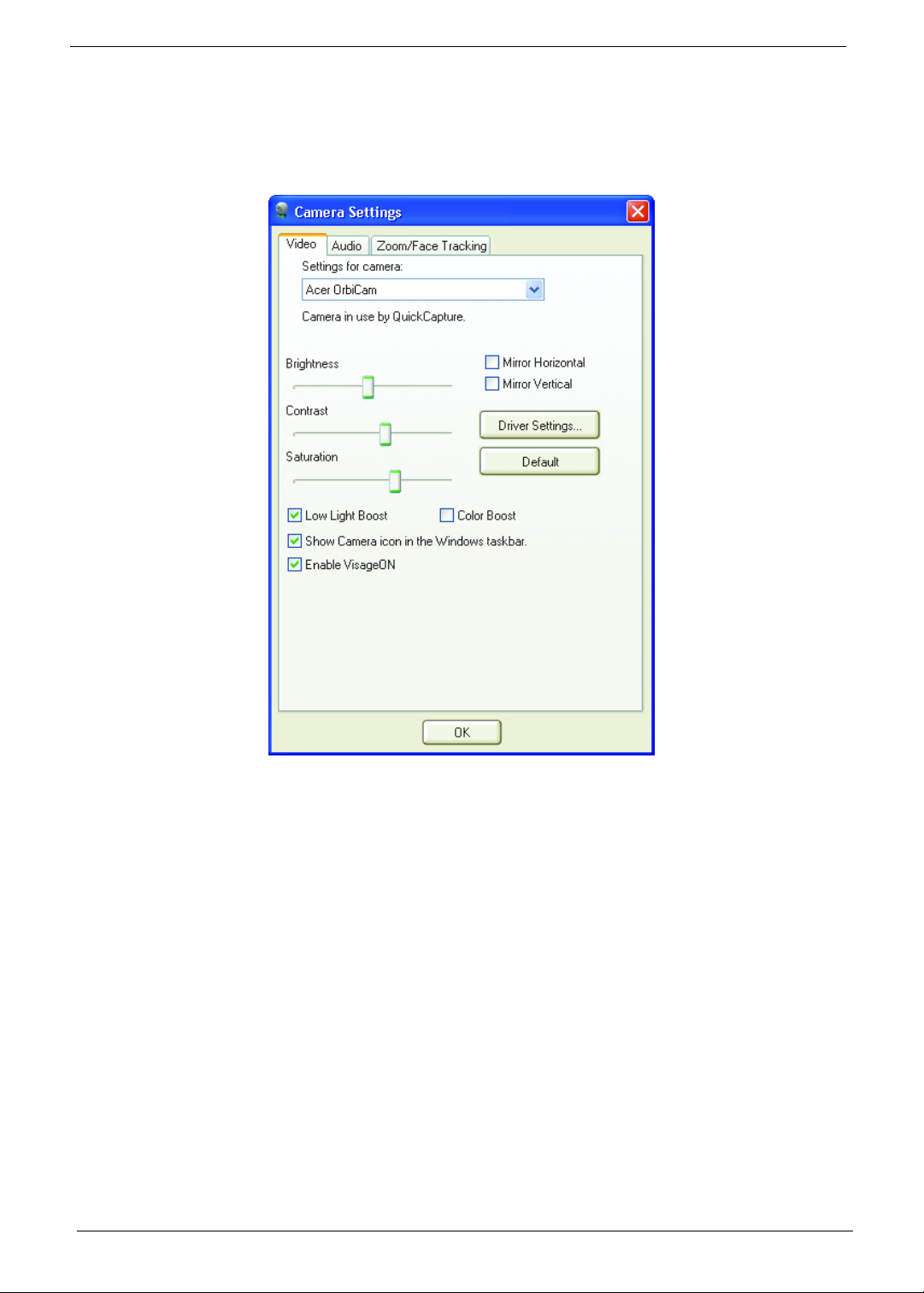
Camera Settings
Basic Settings
Click the Camera Settings icon on the bottom right corner of the capture display, then select Camera Settings
from the pop-up menu. You can adjust the Video, Audio, and Zoom/Face tracking options from this window.
22 Chapter 1
Page 23
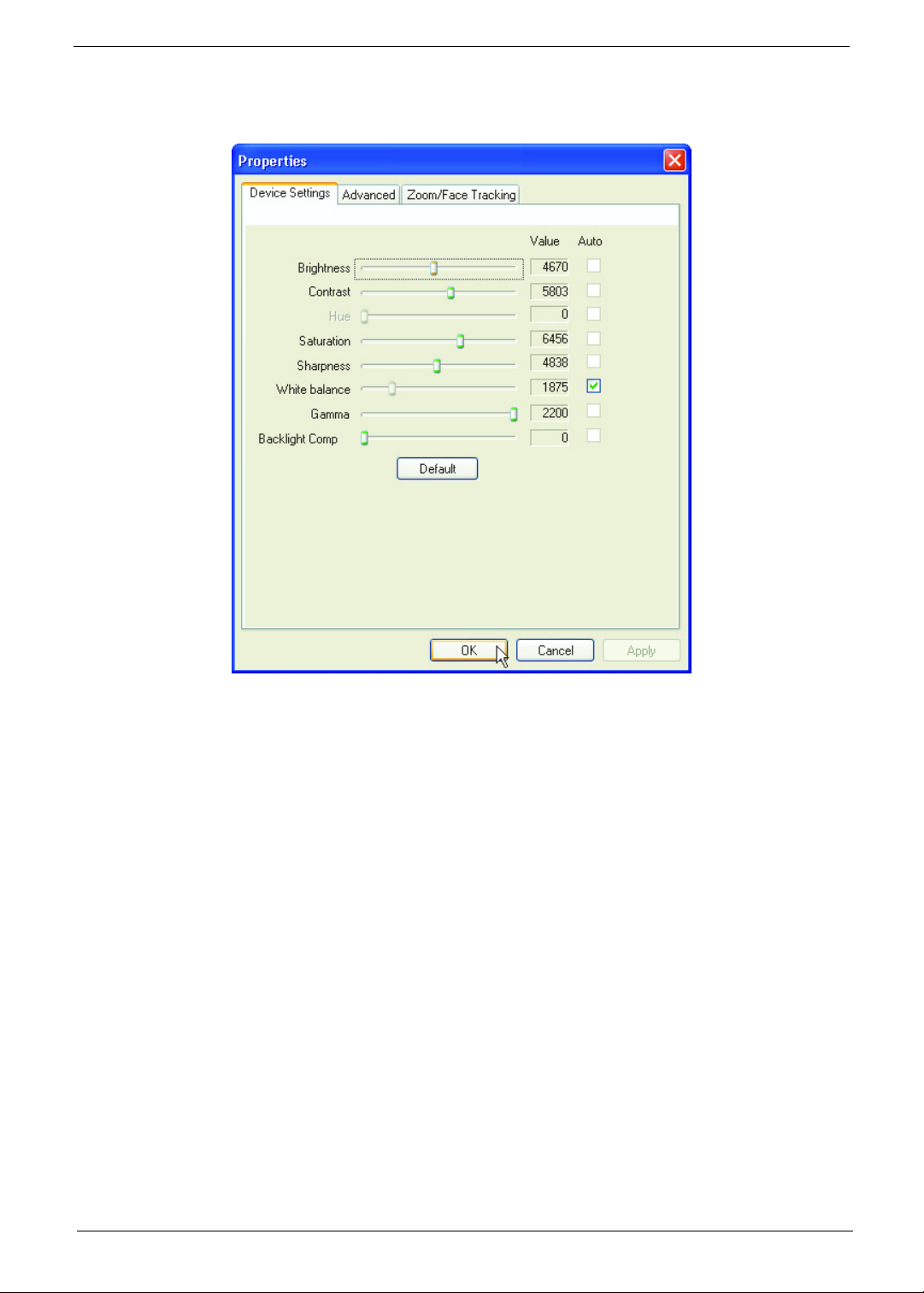
Capture Settings
From the Camera Settings window, click the Driver Settings button. The Properties window will appear.
Device Settings allows you to change the camera brightness, contrast, hue, saturation, sharpness, etc.
Advanced Settings allows you to achieve gain control, implement image mirror, select image enhancements and
anti-flicker settings, and turn on/off the camera indicator.
Zoom/Face Track Settings allows you to adjust the zoom level and turn the face tracking feature on or off.
Capturing Photos/Videos
To capture a photo or a video clip, rotate the Acer OrbiCam to get the desired angle, then click the Take a Picture
or Record a Video button. The Windows Picture and Fax Viewer or the Windows Media Player automatically
launches to display or play a preview of the photo/video clip.
Note: By default, all photos and videos are saved in the My Pictures and My Videos folder.
Chapter 1 23
Page 24
Using the Acer OrbiCam as Webcam
The Acer OrbiCam is automatically selected as the capture device of any instant messenger (IM) application. To
use the Acer OrbiCam as a webcam, open the IM service, then select the video/webcam feature. You can now
broadcast from your location to an IM partner anywhere in the world.
Enabling the Acer VisageON (for 1.3 megapixel camera models only)
The Acer VisageON technology comes with two features: Face tracking. The face tracking feature tracks your
head movement and automatically centers your face in the capture window.
Note: The face tracking feature is not capable of centering your face beyond the capture window frame.
Minimal head movements are tracked more efficiently.
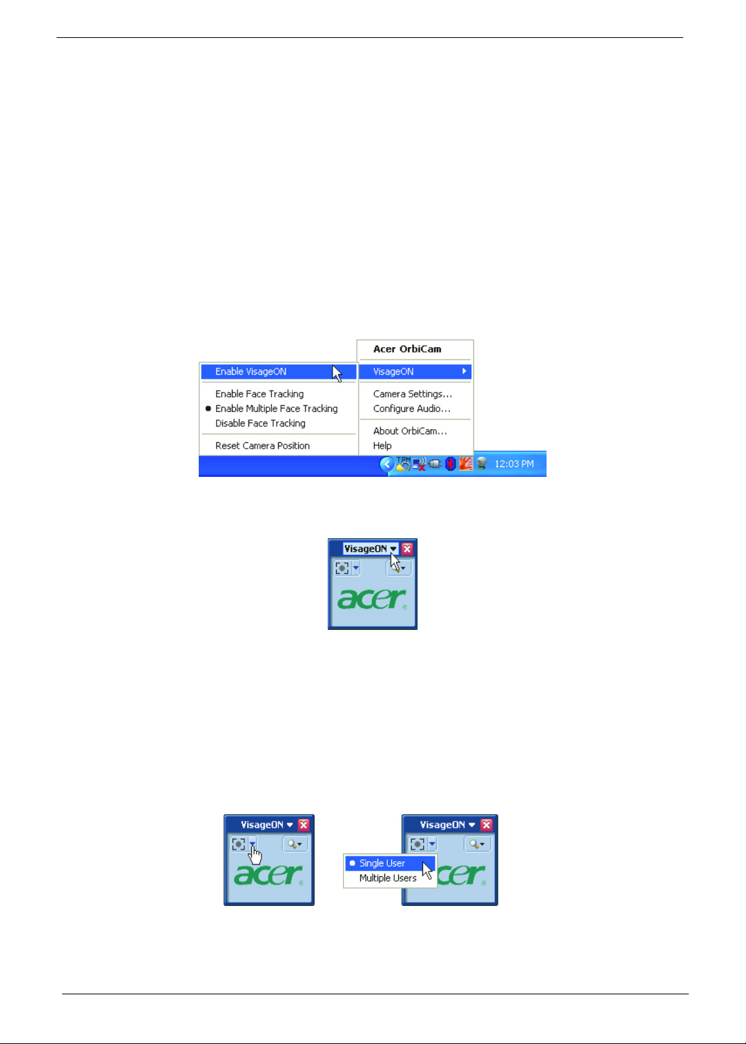
Please follow the steps below to enable the Acer VisageON.
1. Right click on this icon, then select VisageON from the pop-up menu.
The VisageON window will appear as below:
2. Select and apply a video effect in the left section of the VisageON window. Change the face tracking settings
and options in the right section.
Using the Face Tracking Feature
To use the face tracking feature:
1. Click the left icon down arrow button, then select Single User or Multiple Users from the pop-up menu. For
multiple users, the face tracking feature automatically centers all the users’ face in the capture window,
otherwise the utility centers the face of the user closest to the camera.
2. Click the right icon to zoom in/out or reset the current view.
24 Chapter 1
Page 25
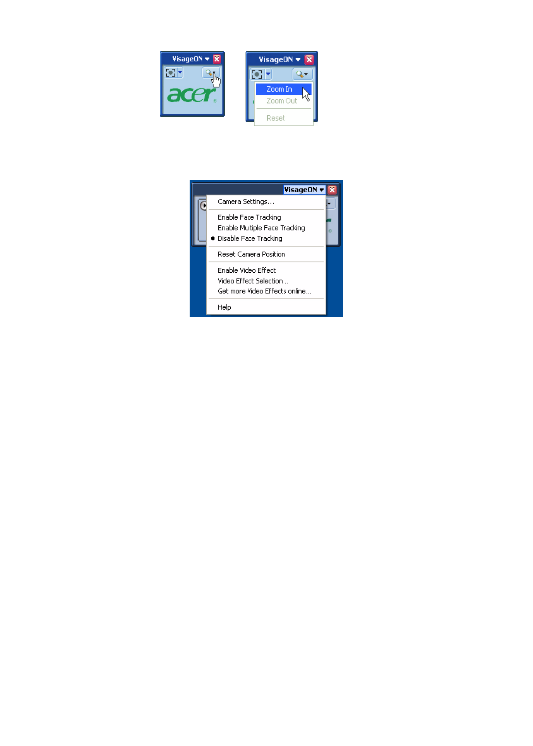
3. Click VisageON to display a menu that allows to change the configuration of the camera, face tracking and
video effects settings.
Chapter 1 25
Page 26

Acer Empowering Technology
Acer’s innovative Empowering Technology toolbar makes it easy to have access to the frequently used functions
and manage the notebook. Displayed by default in the upper-right corner of the screen, it features the following
handy utilities:
• Acer eNet Management hooks up to location-based networks intelligently.
• Acer ePower Management extends battery power via versatile usage profiles.
• Acer ePresentation Management connects to a projector and adjusts dispaly settings conveniently.
• Acer TPM-based eDataSecurity Management protects data with passwords and advanced encryption
algorithms in TPM.
• Acer eLock Management limits access to external storage media and removable data devices.
• Acer eRecovery Management backs up and recovers data flexibly, reliably and completely.
• Acer eSettings Management accesses system information and adjusts settings easily.
• Acer ePerformance Management improves system performance by optimizing disk space, memory and
registry setting.
For more information, right click on the Empowering Technology toolbar, then select the Help or Tutorial function.
Empowering Technology Password
Before using Acer eLock Management and Acer eRecovery Management, You must initialize the Empowering
Technology password. Right click on the Empowering Technology toolbar and select Password Setup to do so. If
you do not initialize the Empowering Technology password, you will be prompted to do so when running Acer
eLock Management or Acer eRecovery Management for the first time.
Note: If you lose your password, there is no method to reset it except by reformatting your notebook or taking
your notebook to an Acer Customer Service Center. Be sure to remember or write down your password.
26 Chapter 1
Page 27
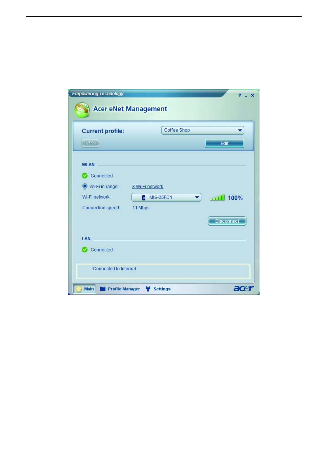
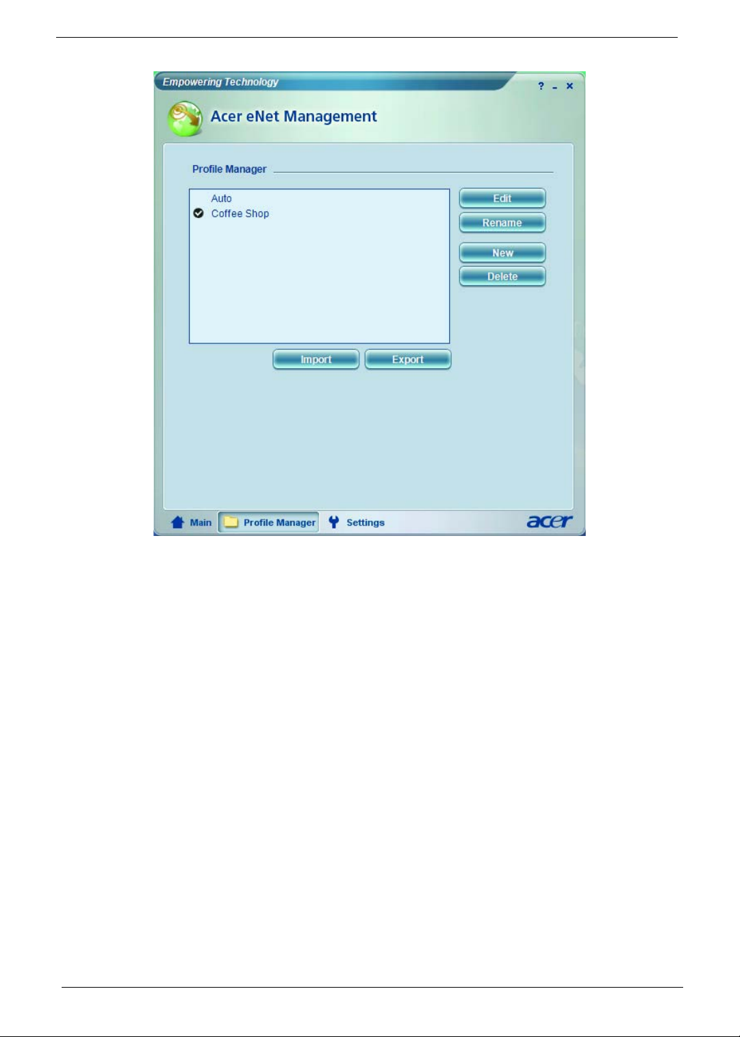
Acer eNet Management
Acer eNet Management helps you to quickly and easily connect to both wired and wireless networks in a variety of
locations. To access this utility, either click on the Acer eNet Management icon on your notebook, or start the
program from the Start menu. You also have the option to set Acer eNet Management to start automatically when
you boot up your PC.
Acer eNet Management automatically detects the best settings for a new location, while offering you the freedom
to manually adjust the settings to meet your needs.
Acer eNet Management can save network settings for a location to a profile, and automatically switch to the
appropriate profile when you move from one location to another. Settings stored include network connection
settings (IP and DNS settings, wireless AP details, etc.), as well as default printer settings.
Security and safety concerns mean that Acer eNet Management does not store username and password
information.
Chapter 1 27
Page 28
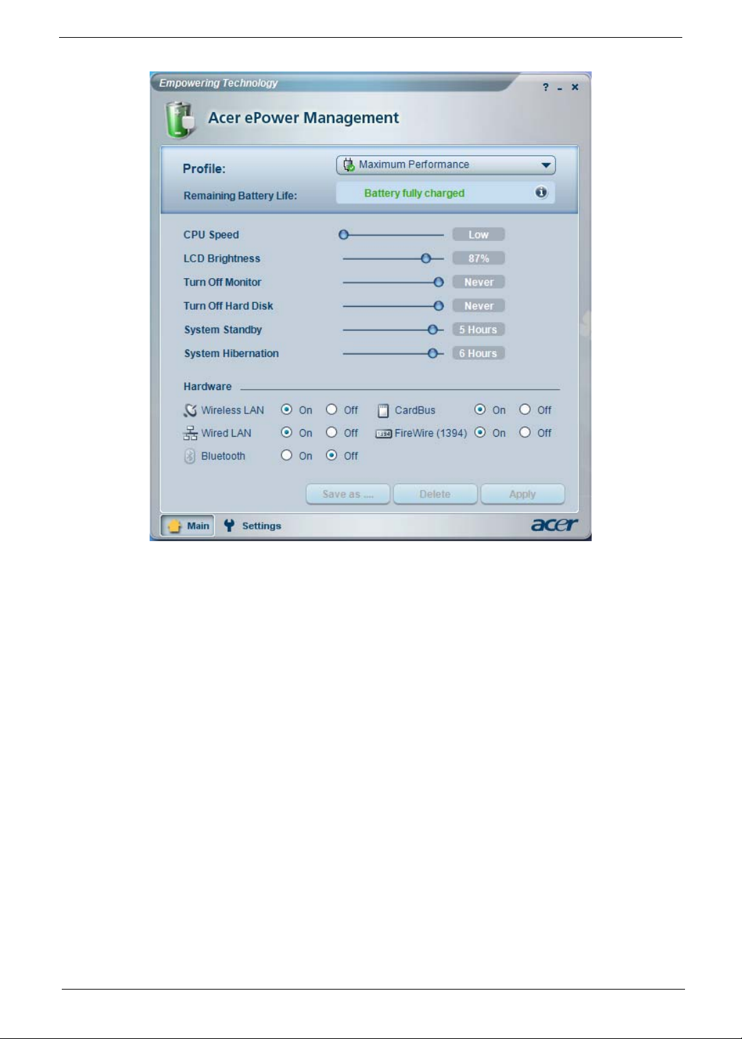
Acer ePower Management
Acer ePower Management features a straightforward user interface. To launch it, select Acer ePower
Management from the Empowering Technology interface.
AC Mode (Adapter Mode)
The default setting is Maximum Performance. You can adjust CPU speed, LCD brightness and other settings, or
click on buttons to turn the following functions on/off: wireless LAN, Bluetooth, CardBus, fireware (1394), wired
LAN and optical device if supported.
DC Mode (Battery Mode)
There are four pre-defined profiles: Entertainment, Presentation, Word Processing, and Battery Life. Y ou can also
define up to three of your own.
To Create a New Power Profile
1. Change power settings as desired.
2. Click Save as... to save to a new power profile.
3. Name the newly created profile.
4. Select whether this profile is for Adapter or Battery mode, then click OK.
5. The new profile will appear in the profile list.
Battery Status
For real-time battery life estimates based on current usage, refer to the panel on the upper half side of the window.
28 Chapter 1
Page 29
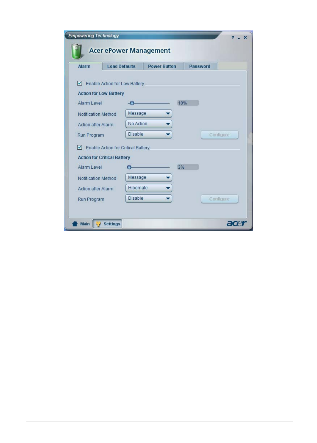
For additional options, click Settings to:
• Set alarms.
• Reload factory defaults.
• Select what actions to be taken when the cover is closed or the power button is pressed.
• Set passwords for accessing the system after Hibernation or Stand-by.
• View information about Acer ePower Management.
Chapter 1 29
Page 30
30 Chapter 1
Page 31

Acer ePresentation Management
Acer ePresentation Management lets you project your computer’s display to an external device or projector using
the hotkey: <Fn> + <F5>. If auto-detection hardware is implemented in the system and the external display
supports it, your system display will be automatically switched out when an external display is connected to the
system. For projectors and external devices that are not auto-detected, launch Acer ePresentation Management to
choose an appropriate display setting.
Note: If the restored resolution is not correct after disconnecting a projector, or you need to use an external
resolution that is not supported by Acer ePresentation Management, adjust your display settings using Display
Properties or the utility provided by the graphics vendor.
Chapter 1 31
Page 32

Acer TPM-Based eDataSecurity Management
Acer TPM-based eDataSecurity Management is a handy file encryption utility that protects the files from being
accessed by unauthorized persons. It is conveniently integrated with Windows Explorer as a shell extension for
quick and easy data encryption/decryption and also supports on-the-fly file encryption for MSN Messenger and
Microsoft Outlook.
The Acer eDataSecurity Management setup wizard will prompt you for a supervisor password and default
encryption. This encryption will be used to encrypt files by default, or you can choose to enter your own file-specific
password when encrypting a file.
Acer eDataSecurity Management can be integrated with TPM on computers equipped with the TPM hardware. On
computers equipped with the TPM hardware, there will be additional Acer eDataSecurity Management system
setup and administration procedures which allow the user to utilize TPM for the PSD and the File/Folder
encryption functions. If the Use TPM option is selected during Acer eDataSecurity Management’s initial system
setup or system administration, the PSD and the File/Folder encryption functions will be protected by TPM.
Note: The password used to encrypt a file is the unique key that the system needs to decrypt it. If you lose the
password, the supervisor password is the only other key capable of decrypting the file. If you lose both
passwords, there will be no way to decrypt your encrypted file! Be sure to safeguard all related passwords!
32 Chapter 1
Page 33

Chapter 1 33
Page 34

Acer eRecovery Management
Acer eRecovery Management is a powerful utility with the need for recovery disks provided by the manufacturer.
The Acer eRecovery Management utility occupies space in a hidden partition on the system’s HDD. Be default,
user-created backups are stored on D:\ drive. Acer eRecovery Management provides:
• Password protection
• Recovery of applications and drives
• Image or data backup:
• Backup to HDD (set recovery point)
• Backup to CD or DVD
• Image/data recovery tools:
• Recovery from a hidden partition (factory defaults)
• Recovery from the HDD (most recent user-defined recovery point)
• Recovery from CD or DVD
Note: If the computer did not come with a Recovery CD or System CD, please use Acer eRecovery
Management’s System backup to optical disk feature to burn a backup image to CD or DVD . To ensure the
best results when recovering the system using a CD or Acer eRecovery Management, detach all peripherals
(except external Acer ODD, if equipped), including the Acer ezDock.
Acer eSettings Management
Acer eSettings Management allows you to inspect hardware specification, change BIOS passwords or other
Windows settings, and to monitor the system health status.
Acer eSettings Management also:
34 Chapter 1
Page 35

• Provides a simple graphical user interface for navigation.
• Displays general system status and advanced monitoring for power users on Acer computer.
Chapter 1 35
Page 36

Acer ePerformance Management
Acer ePerformance Management is a system optimization tool that boosts the performance of the Acer notebook.
It provides an express optimization method to release unused memory and disk space quickly . The user can also
enable advanced options for full control over the following options:
• Disk optimization: removes unneeded items and files.
• Speed optimization: improves the usability and performance of the Windows XP system.
• Memory optimization: releases unused memory and check usage.
36 Chapter 1
Page 37

Using the System Utilities
Note: The system utilities work under Microsoft Windows XP only.
Acer GridVista (dual-display compatible)
Note: This feature is only available on certain models.
To enable the dual monitor feature of the notebook, first ensure that the second monitor is connected, then select
Start, Control Panel, Display and click on Settings. Select the secondary monitor (2) icon in the display box and
then click the check box Extend my windows desktop onto this monitor . Finally, click Apply to confirm the new
settings and click OK to complete the process.
Acer GridVista is a handy utility that offers four pre-defined display settings so you can view multiple windows on
the same screen. To access this function, please go to Start > All Programs and click on Acer GridVista. You
may choose any one of the four display settings indicated below:
Double (vertical), Triple (primary at left), Triple (primary at right), or Quad
Acer Gridvista is dual-display compatible, allowing two displays to be partitioned independently. Acer GridVista is
simple to set up:
1. Run Acer GridVista and select your preferred screen configuration for each display from the task bar.
2. Drag and drop each window into the appropriate grid.
3. Enjoy the convenience of a well-organized desktop.
Chapter 1 37
Page 38

Note: Please ensure that the resolution setting of the second monitor is set to the manufacturer's
recommended value.
Launch Manager
Launch Manager allows you to set the four easy-launch buttons located above the keyboard. You can access the
Launch Manager by clicking on Start > All Programs > Launch Manager to start the application.
38 Chapter 1
Page 39

Hardware Specifications and Configurations
Processor
Item Specification
CPU type Intel CPU Core2Dual
Core logic
CPU package uFCPGA, Socket P
CPU core voltage 0.944~1.3V
CPU Fan True Value Table
TEST Condition: 35W@Ambient 35 degree C
CPU Temperature Fan Speed Acoustic Level
Core 0 Core 1 (rpm) (dBA)
86 86 3700 39
88 88 3450 36.5
91 91 3150 34.5
95 95 2800 31
BIOS
Item Specification
BIOS vendor Phneoix
BIOS Version
BIOS ROM type Flash ROM
BIOS ROM size 1MB
BIOS package 8-PIN SOIC
Supported protocols ACPI 1.0b/2.0/3.0, PCI 2.2, System/HDD Password Security Control, INT
BIOS password control Set by setup manual
®
965PM+ICH8M-E
Intel
13h Extensions, PnP BIOS 1.0a, SMBIOS 2.4,BIOS Boot Specification
(Compal, Phoenix, Intel),Simple Boot Flag 1.0, Boot Block, PCI Bus Power
Management Interface Specification, USB1.1/2.0, IEEE 1394 1.0, USB/
1394 CD-ROM Boot Up support, PC Card standard 1995 (PCMCIA 3.0
Compliant Device), IrDA 1.0, Support HD audio, WfM 2.0, PXE 2.1(Preboot
Execution Environment), BIS 1.0 (Boot Integrity Service Application
Program Interface), PC2002 and PC2005 Compliant, Intel Enganced
SpeedStep Technology,AHCI support
NOTE: If you need to check PXE version, press F2 to enter BIOS then enable boot from LAN function. After
that, power off the system and remove the HDD. Last, reboot the laptop. Then you will see PXE version
displaying on the screen.
Second Level Cache
Item Specification
Cache controller Built-in CPU
Cache size 4MB
1st level cache control Always enabled
2st level cache control Always enabled
Cache scheme control Fixed in write-back
Chapter 1 39
Page 40

System Memory
Item Specification
Memory controller
Memory size 0MB (no on-board memory)
DIMM socket number 2 sockets
Supports memory size per socket 2GB
Supports maximum memory size 4GB
Supports DIMM type DDR 2 Synchronous DRAM
Supports DIMM Speed 533/667 MHz
Supports DIMM voltage 1.8V and 0.9V
Supports DIMM package 200-pin soDIMM
Memory module combinations You can install memory modules in any combinations as long as they
®
PM965
Intel
match the above specifications.
Memory Combinations
Slot 1 Slot 2 Total Memory
0MB 128MB 128MB
0MB 256MB 256MB
0MB 512MB 512MB
0MB 1024MB 1024MB
0MB 2048MB 2048MB
128MB 128MB 256MB
128MB 256MB 384MB
128MB 512MB 640MB
128MB 1024MB 1152MB
128MB 2048MB 2176MB
256MB 128MB 384MB
256MB 256MB 512MB
256MB 512MB 768MB
256MB 1024MB 1280MB
256MB 2048MB 2304MB
512MB 128MB 640MB
512MB 256MB 768MB
512MB 512MB 1024MB
512MB 1024MB 1536MB
512MB 2048MB 2560MB
1024MB 0MB 1024MB
1024MB 128MB 1152MB
1024MB 256MB 1280MB
1024MB 512MB 1536MB
1024MB 1024MB 2048MB
1024MB 2048MB 3072MB
NOTE: Above table lists some system memory configurations. You may combine DIMMs with various
capacities to form other combinations. On above table, the configuration of slot 1 and slot 2 could be
40 Chapter 1
Page 41

reversed.
LAN Interface
Item Specification
Chipset Broadcom 5787
Supports LAN protocol 10/100/1000 Ethernet
PCI-E Giga
LAN connector type RJ45
LAN connector location Rear side
Features Integrated 10/100/1000 BASE-T transceiver
Wake on LAN support compliant with ACPI 2.0
PCI v2.2
Modem Interface
Item Specification
Data modem data baud rate (bps) 56K
Supports modem protocol V.92
Modem connector type RJ11
Modem connector location Left side
Bluetooth Interface
Item Specification
Chipset Built-in ICH8M-E
Data throughput 723 bps (full speed data rate)
Protocol Bluetooth 1.1 (Upgradeable to Bluetooth 1.2 when SIG
Interface USB 2.0
Connector type USB
specification is ratified).
Hard Disk Drive Interface
Item
Vendor &
Model Name
Capacity (MB) 80000 120000 160000
Bytes per
sector
Data heads 2 3 for Seagate and WD
Drive Format
Disks122
Spindle speed
(RPM)
Performance Specifications
Buffer size 8M 8M 8M
Interface SATA SATA SATA
Max. media
transfer rate
(disk-buffer,
Mbytes/s)
HGST HTS541680J9SA00
WD WD800BEVS-22RST0
512 512 512
5400 RPM 5400 RPM 5400 RPM
100,150 150,300,100,150 300,150,100,150
Seagate ST9120822AS
Toshiba MK1237GSX
HGST HTS541612J9SA00
WD WD1200BEVS-22RST0
4 for Toshiba and HGST
TOSHIBA MK1637GSX
SEAGATE ST9160821AS
HGST HTS541616J9SA00
WD WD1600BEVS-22RST0
4
Chapter 1 41
Page 42

Hard Disk Drive Interface
Item
Data transfer
rate
(host~buffer,
Mbytes/s)
DC Power Requirements
Voltage
tolerance
100 MB/Sec.
Ultra DMA mode-5
5V(DC) +/- 5% 5V(DC) +/- 5% 5V(DC) +/- 5%
100 MB/Sec.
Ultra DMA mode-5
100 MB/Sec.
Ultra DMA mode-5
DVD-SuperMulti Interface
Item Specification
Vendor & model name TOSHIBA 8X TS-L632D
PHILIPS 8X DS-8A1P
HLDS 8X GSA-T20N
Performance Specification With CD Diskette With DVD Diskette
Transfer rate (KB/sec) Sustained:
Max 3.6Mbytes/sec
Buffer Memory 2MB
Interface E nhanced IDE(ATAPI) compatible
Applicable disc format Support disc formats
1. Reads data in each CD-ROM, CD-ROM XA, CD-1, Video CD, CD-Extra and
CD-Plus
2. Reads data in super Audio CD (SACD) Hybrid type
3. Reads standard CD-DA
4. Reads and writes CD-R discs
5. Reads and writes CD-RW andHSRW discs
6. Reads and writes US & US+RW
7. Reads data in each DVD-ROM and DVD-Dual
8. Reads and writes in each DVD-R (Ver. 2.0 for general), DVD-RW and
DVD+R/RW (Ver1.1)
9.Reads and writes DVD+-R Dual
10.Reads and writes DVD-RAM
Loading mechanism Load: Manual
Release: (a) Electrical Release (Release Button)
(b) Release by ATAPI command
(c) Emergency Release
Power Requirement
Input Voltage 5 V +/- 5 % (Operating)
Sustained:
Max 10.8Mbytes/sec
Audio Interface
Item Specification
Audio Controller Realtek ALC268(Dolby version) (co-layout w/ 888S)
Audio onboard or optional Built-in
Mono or Stereo Stereo
Resolution 18 bit stereo full duplex
Compatibility HD audio Interface; S/PDIF output for PCM or AC-3 content
Sampling rate 1Hz resolution VSR (Variable Sampling Rate)
Internal microphone Yes
Internal speaker / Quantity Yes/2(1.5W speakers)
Supports PnP DMA channel DMA channel 0
DMA channel 1
Supports PnP IRQ IRQ10, IRQ11
42 Chapter 1
Page 43

Video Interface
Item Specification
Chipset
Package
Interface Internal PCIE
Supports ZV (Zoomed Video) port
nVdia NV8P-GS
MXM
820-ball BGA 33mm x33mm
Video Memory
Item Specification
Chipset
Memory size Dedicated Video memory size:
128-bit DDR2/GDDR3/GDDR4
Interface
USB Port
Item Specification
Chipset Built-in ICH8M-E
USB Compliancy Level 2.0
OHCI USB 1.1 and USB 2.0 Host controller
Number of USB port 4
Location One on the left side; three on the right side
Serial port function control Enable/Disable by BIOS Setup
PCMCIA Port
DDR2/GDDR3/GDDR4
Item Specification
PCMCIA controller TI PCI 7412
Supports card type Type-II
Number of slots One type-II
Access location Left panel
Supports ZV (Zoomed Video) port No ZV support
Supports 32 bit CardBus Yes
Express Card Interface
Item Specification
Express card controller Built-in ICH8M-E
Supports card type 75mmx54mm(W)x5mm
Number of slots One
Access location Right panel
Interface PCI Express
System Board Major Chips
Item Controller
Core logic
®
Crestline PM965 + ICH8M-E
Intel
Chapter 1 43
Page 44

System Board Major Chips
Item Controller
VGA
LAN Broadcom 5787
USB 2.0 Built in ICH8M-E
Super I/O controller ITE 8305E
MODEM Foxconn T60M955
Bluetooth Foxconn T60H928.01
Wireless 802.11 a+b+g Built-in ICH8-M
PCMCIA TI PCI 7412
Audio Realtek ALC268(Dolby version)
nVdia NV8P-GS MXM
Keyboard
Item Specification
Keyboard controller ITE 8512E
Total number of keypads 88-/89-key
Windows logo key Yes
Internal & external keyboard work
simultaneously
Plug USB keyboard to the USB port directly: Yes
Battery
Item Specification
Vendor & model name BATTERY PACK SANYO LI-ION 8
Battery Type Li-ion
Pack capacity 4800 mAH
Number of battery cell 8
Package configuration 4 cells in series, 2 series in parallel
Normal voltage 14.8V
Charge voltage 16.8+-0.2V
CELL2.4, 4800MAH
BATTRY PACK SONY LI-ION
8CELL2.4, 4800MAH
LCD 20.1” inch
Item Specification
Vendor & model name AUO
M201EW02 V9
GLARE
Screen Diagonal (mm) 20.1 inches
Active Area (mm) 304.1x228.1
Display resolution (pixels) 1680x1050
WSXGA
Pixel Pitch 0.099x0.297
Pixel Arrangement R.G.B. Vertical
Display Mode Normally White
Stripe
44 Chapter 1
Page 45

LCD 20.1” inch
Item Specification
Typical White Luminance (cd/m2)
also called Brightness
Luminance Uniformity N/A
Contrast Ratio 300
Response Time (Optical Rise Time/Fall
Time)msec
Nominal Input Voltage VDD +3.3V
Typical Power Consumption (watt) 3.96
Weight 570
Physical Size(mm) 317.3x242.0x5.
Electrical Interface 1 channel LVDS
Support Color 262,144
Viewing Angle (degree)
Horizontal: Right/Left
Vertial: Upper/Lower
Temperature Range( C)
Operating
Storage (shipping)
°
300
8
9
45/45
15/35
0 to +50
-25 to +60
LCD Inverter
Item Specification
Vendor & model name TDK
Brightness conditions N/A
Input voltage (V) 9~21
Input current (mA) 2.56 (max)
Output voltage (V, rms) 780V (2000V for kick off)
Output current (mA, rms) 6.5 (max)
Output voltage frequency (k Hz) 65K Hz (max)
AC Adaptor
Item Specification
Input rating 90V AC to 264V AC, 47Hz to 63Hz
Maximum input AC current 1.7A
Inrush current 220A@115VAC
220A@230VAC
Efficiency 82% min. @115VAC input full load
System Power Management
ACPI mode Power Management
Mech. Off (G3) All devices in the system are turned off completely.
Soft Off (G2/S5) OS initiated shutdown. All devices in the system are turned off
Working (G0/S0) Individual devices such as the CPU and hard disc may be power
completely.
managed in this state.
Chapter 1 45
Page 46

System Power Management
ACPI mode Power Management
Suspend to RAM (S3) CPU set power down
VGA Suspend
PCMCIA Suspend
Audio Power Down
Hard Disk Power Down
CD-ROM Power Down
Super I/O Low Power mode
Save to Disk (S4) Also called Hibernation Mode. System saves all system states and
data onto the disc prior to power off the whole system.
System Fan True Value Table
46 Chapter 1
Page 47

System Utilities
BIOS Setup Utility
The BIOS Setup Utility is a hardware configuration program built into your computer’s BIOS (Basic Input/
Output System).
Y our computer is already properly configured and optimized, and you do not need to run this utility . However, if
you encounter configuration problems, you may need to run Setup. Please also refer to Chapter 4
Troubleshooting when problem arises.
To activate the BIOS Utility, press F2 during POST (when “Press <F2> to enter Setup” message is prompted
on the bottom of screen).
Press <F12> during POST to enter multi-boot menu. In this menu, user can change boot device without
entering BIOS SETUP Utility. However, The default parameter of F12 Boot Menu is set to “disabled”. If you
want to change boot device without entering BIOS Setup Utility, please set the parameter to “enabled”.
Chapter 2
Chapter 2 47
Page 48

Navigating the BIOS Utility
There are six menu options: Information, Main, Advanced, Security, Boot, and Exit.
Follow these instructions:
q To choose a menu, use the cursor left/right keys .
q To choose a parameter, use the cursor up/down keys .
q To change the value of a parameter, press F5 or F6.
q A plus sign (+) in dicates the item has sub-items. Press Enter to expand this item.
q Press Esc while you are in any of the menu options to go to the Exit menu.
q In any menu, you can load default settings by pressing F9. You can also press F10 to save any
changes made and exit the BIOS Setup Utility.
NOTE: You can change the value of a parameter if it is enclosed in square brackets. Navigation keys for a
particular menu are shown on the bottom of the screen. Help for parameters are found in the Item
Specific Help part of the screen. Read this carefully when making changes to parameter values. Please
note that system information is subject to different models.
48 Chapter 2
Page 49

Information
NOTE: The system information is subject to different models.
Parameter Description
CPU Type This field shows the CPU type of the system.
CPU Speed This field shows the CPU speed of the system.
IDE0 Model Name This field shows the model name of HDD installed on system.
IDE1 Model Name This field shows the model name of HDD installed on system
System BIOS version Displays system BIOS version.
VGA BIOS Version This field displays the VGA firmware version of the system.
Serial Number This field displays the serial number of this unit.
Asset Tag Number This field displays the asset tag number of the system.
Product Name This field shows product name of the system.
Manufacturer Name This field displays the manufacturer of this system.
UUID Number This will be visible only when an internal LAN device is presenting.
UUID=32bytes
Chapter 2 49
Page 50

Main
The Main screen displays a summary of your computer hardware information, and also includes basic setup
parameters. It allows the user to specify standard IBM PC AT system parameters.
NOTE: The screen above is for your reference only. Actual values may differ.
50 Chapter 2
Page 51

The table below describes the parameters in this screen. Settings in boldface are the default and suggested
parameter settings.
Parameter Description Format/Option
System Time Sets the system time. The hours are displayed
with 24-hour format.
System Date Sets the system date. Format MM/DD/YYYY (month/day/
System Memory This field reports the memory size of the system.
Memory size is fixed to 640MB
Extended Memory This field reports the memory size of the
extended memory in the system.
Extended Memory size=Total memory size-1MB
VGA Memory Shows the VGA memory size. VGA Memory
size=64/128MB
Quiet Boot Determines if Customer Logo will be displayed or
not; shows Summary Screen is disabled or
enabled.
Enabled: Customer Logo is displayed, and
Summary Screen is disabled.
Disabled: Customer Logo is not displayed, and
Summary Screen is enabled.
Network Boot Enables, disables the system boot from LAN
(remote server).
F12 Boot Menu Enables, disables Boot Menu during POST.
D2D Recovery Enables, disables D2D Recovery function. The
function allows the user to create a hidden
partition on hard disc drive to store operation
system and restore the system to factory
defaults.
Format: HH:MM:SS
(hour:minute:second) System Time
year)
System Date
Option:
Enabled or Disabled
Option:
Enabled or Disabled
Option:
Disabled or Enabled
Option:
Enabled or Disabled
NOTE: The sub-items under each device will not be shown if the device control is set to disable or auto. This is
because the user is not allowed to control the settings in these cases.
Chapter 2 51
Page 52

Advanced
The Advanced screen displays advanced settings in BIOS.
The table below describes the parameters in this screen. Settings in boldface are the default and suggested
parameter settings.
Parameter Description Option
Serial port A Displays the settings of the serial port
Parallel port Shows the settings of the parallel port
Enabled, Disabled,
Enabled, Disabled,
AUTO
AUTO
52 Chapter 2
Page 53

Security
The Security screen contains parameters that help safeguard and protect your computer from unauthorized
use.
Chapter 2 53
Page 54

The table below describes the parameters in this screen. Settings in boldface are the default and suggested
parameter settings.
Parameter Description Option
User Password is Shows the setting of the user password.
Supervisor Password is Shows the setting of the Supervisor password
Set User Password Press Enter to set the user password. When
user password is set, this password protects
the BIOS Setup Utility from unauthorized
access. The user can enter Setup menu only
and does not have right to change the value of
parameters.
Set Supervisor Password Press Enter to set the supervisor password.
When set, this password protects the BIOS
Setup Utility from unauthorized access. The
user can not either enter the Setup menu nor
change the value of parameters.
Password on Boot Defines whether a password is required or not
while the events defined in this group
happened. The following sub-options are all
requires the Supervisor password for changes
and should be grayed out if the user password
was used to enter setup.
Clear or Set
Clear or Set
Disabled or Enabled
NOTE: When you are prompted to enter a password, you have three tries before the system halts. Don’t forget
your password. If you forget your password, you may have to return your notebook computer to your
dealer to reset it.
Setting a Password
Follow these steps as you set the user or the supervisor password:
1. Use the cursor up/down key to highlight the Set Supervisor Password parameter and press the Enter key.
The Set Supervisor Password box appears:
2. Type a password in the “Enter New Password” field. The password length can not exceeds 8
alphanumeric characters (A-Z, a-z, 0-9, not case sensitive). Retype the password in the “Confirm New
Password” field.
IMPORTANT:Be very careful when typing your password because the characters do not appear on the screen.
3. Press Enter.
After setting the password, the computer sets the User Password parameter to “Set”.
4. If desired, you can enable the Password on boot parameter.
5. When you are done, press F10 to save the changes and exit the BIOS Setup Utility.
Removing a Password
Follow these steps:
1. Use the cursor up/down key to highlight the Set Supervisor Password parameter and press the Enter key.
The Set Password box appears:
54 Chapter 2
Page 55

2. Type the current password in the Enter Current Passw ord field and press Enter.
3. Press Enter twice without typing anything in the Enter New Password and Confirm New Password fields.
The computer then sets the Supervisor Password parameter to “Clear”.
4. When you have changed the settings, press F10 to save the changes and exit the BIOS Setup Utility.
Changing a Password
1. Use the cursor up/down key to highlight to highlight the Set Supervisor Password parameter and press
the Enter key. The Set Password box appears:
2. Type the current password in the Enter Current Passw ord field and press Enter.
3. Type a password in the Enter New Password field. Retype the password in the Confirm New Password
field.
4. Press Enter. After setting the password, the computer sets the User Password parameter to “Set”.
5. If desired, you can enable the Password on boot parameter.
6. When you are done, press F10 to save the changes and exit the BIOS Setup Utility.
If the verification is OK, the screen will display as following.
The password setting is complete after the user presses Enter.
If the current password entered does not match the actual current password, the screen will show you the
Setup Warning.
Chapter 2 55
Page 56

If the new password and confirm new password strings do not match, the screen will display the following
message.
56 Chapter 2
Page 57

Boot
This menu allows the user to decide the order of boot devices to load the operating system. Bootable devices
includes the distette drive in module bay, the onboard hard disk drive, wake up on LAN, USB KEY and the CDROM in module bay.
Chapter 2 57
Page 58

Exit
The Exit screen contains parameters that help safeguard and protect your computer from unauthorized use.
The table below describes the parameters in this screen.
Parameter Description
Exit Saving Changes Exit System Setup and save your changes to CMOS.
Exit Discarding Changes Exit utility without saving setup data to CMOS.
Load Setup Default Load default values for all SETUP item.
Discard Changes Load previous values from CMOS for all SETUP items.
Save Changes Save Setup Data to CMOS.
58 Chapter 2
Page 59

BIOS Flash Utility
The BIOS flash memory update is required for the following conditions:
q New versions of system programs
q New features or options
q Restore a BIOS when it becomes corrupted.
Use the Phlash utility to update the system BIOS flash ROM.
NOTE: If you do not have a crisis recovery diskette at hand, then you should create a Crisis Recovery
Diskette before you use the Phlash utility.
NOTE: Do not install memory-related drivers (XMS, EMS, DPMI) when you use the Phlash.
NOTE: Please use the AC adaptor power supply when you run the Phlash utility. If the battery pack does not
contain enough power to finish BIOS flash, you may not boot the system because the BIOS is not
completely loaded.
Fellow the steps below to run the Phlash.
1. Prepare a bootable diskette.
2. Copy the flash utilities and BIOS code to the bootable diskette.
3. Then boot the system from the bootable diskette. Type “Phlash16 ****.rom” (if XMS is present, then add
parameter “ /x“ in the end).
4. BIOS flash will be auto-execution, then power off system.
5. Remove diskette and power on system.
Chapter 2 59
Page 60

60 Chapter 2
Page 61

Machine Disassembly and Replacement
This chapter contains step-by-step procedures on how to disassemble the notebook computer Aspire 9920 for
maintenance and troubleshooting.
To disassemble the computer, you need the following tools:
q Wrist grounding strap and conductive mat for preventing electrostatic discharge
q Small Philips screw driver
q Philips screwdriver
q Plastic flat head screw driver
q Tweezers
NOTE: The screws for the different components vary in size. During the disassembly process, group the
screws with the corresponding components to avoid mismatch when putting back the components.
When you remove the stripe cover, please be careful not to scrape the cover.
Chapter 3
Chapter 3 61
Page 62

General Information
Before You Begin
Before proceeding with the disassembly procedure, make sure that you do the following:
1. Turn off the power to the system and all peripherals.
2. Unplug the AC adapter and all power and signal cables from the system.
3. Remove the battery pack.
62 Chapter 3
Page 63

Disassembly Procedure Flowchart
The flowchart on the succeeding page gives you a graphic representation on the entire disassembly sequence
and instructs you on the components that need to be removed during servicing. For example, if you want to
remove the system board, you must first remove the keyboard, then disassemble the inside assembly frame in
that order.
Chapter 3 63
Page 64

Screw List
Item Description Part Number
A SCREW M2.5*3(NL) 86.TAVV5.001
B SCREW M2.5*6(NL) 86.TAVV5.002
C SCREW M2.5*10(NL) 86.TAVV5.003
D SCREW M2.5*15(NL) 86.TAVV5.004
E SCREW M2*2.2 86.TAVV5.005
F SCREW M2*3(NL) 86.TAVV5.006
G SCREW M2*4 86.TAVV5.007
H SCREW M3*4(NL) 86.TAVV5.008
I SCREW D-SUB 4#X40* 1/5-NI (NL) 86.TAVV5.009
64 Chapter 3
Page 65

Removing the Battery Pack
1. Release the battery.
2. Slide the battery latch then remove the battery.
Chapter 3 65
Page 66

Removing the HDD/Memory Module/Wireless LAN Card/TV Tuner Card/ System Fan/Thermal Modules/CPU and the LCD Module
Removing the HDD
1. Remove the three screws fastening the HDD door.
2. Detach the HDD door from the notebook.
3. Then disconnect the two HDD as shown (Some notebooks may have only one HDD).
Removing the Memory Module
4. Remove the four screws holding the CTO cover.
5. Detach the CTO cover from the main unit.
6. Pop out the memory module from the DIMM socket then remove it (If the notebook has two memory
modules, then repeat this step).
Removing the Wireless LAN Card/TV Tunder Card and System Fan
7. Remove the two screws fastening the wireless LAN card.
66 Chapter 3
Page 67

8. Disconnect the main and auxiliary antennae from the wireless LAN card.
9. Then take out the wireless LAN card from the main unit.
10. Remove the two screws fastening the TV tuner card.
11. Disconnect the TV-in cable then remove the TV tuner card.
12. Remove two screws holding the support holder as shown.
13. Remove four screws fastening the support holder on the rear side as shown.
14. Detach the support holder from the main unit.
15. Remove the three screws holding the system fan.
16. Disconnect the fan cable from the main board.
17. Take out the system fan from the main unit as shown.
Chapter 3 67
Page 68

Removing the Thermal Modules and the CPU
18. Remove the two screws holding the finger heatsink.
19. Detach the finger heatsink from the main board.
20. Then take out the CPU heatsink from the main board.
21. Use a flat screwdriver to release the CPU lock (Turn counter clock-wise) then remove the CPU carefully.
22. Remove the two screws fastening the MXM heatsink.
23. Detach the MXM heatsink from the main board.
24. Remove the two screws fastening the MXM card
25. Remove the MXM card carefully.
68 Chapter 3
Page 69

Removing the ODD and Dummy cards
26. Remove the screw fastening the optical disk drive module on the bottom.
27. Use a tool to push the optical disk drive module outwards and remove the ODD module.
28. Then remove the PC dummy card.
29. Remove the express dummy card.
Chapter 3 69
Page 70

Removing the LCD Module
30. Detach the middle cover from the rear side as shown.
31. Then detach the middle cover from the front side and remove it.
32. Take out the LCD cable from the groove.
33. Disconnect the LCD cable from the main board.
34. Remove the six screws holding the LCM module.
35. Detach the LCD module from the main unit.
70 Chapter 3
Page 71

Disassembling the Main Unit
Separate the Main Unit Into the Upper and the Lower Case Assembly
1. Release the four keyboard lock as shown (Use a flat screwdriver and push the keyboard lock upwards).
2. Turn over the keyboard as the image shows.
3. Disconnect the Keyboard FFC from the main board
4. Then remove the keyboard from the main unit.
123
5. Remove the 18 screws fastening the upper case and the lower case assembly as shown.
6. Disconnect the Speaker cable from the main board.
4
7. Disconnect the Audio board FFC from the main board.
8. Disconnect the Hotkey board FFC from the main board.
9. Disconnect the Tou ch pad FFC from the main board.
10. Carefully detach the upper case assembly from the lower case assembly.
Chapter 3 71
Page 72

Disassembling the Lower Case Assembly
11. Disconnect the bluetooth cable from the main board and detach the bluetooth module fromt the lower
case.
12. Remove the two screws fastening the modem board and disconnect the modem board from the main
board.
13. Disconnect the modem cable and remove the modem board.
14. Remove the three screws fastening the main board to the lower case.
15. Detach the main board from the lower case assembly.
72 Chapter 3
Page 73

16. Remove the three screws holding the IO board to the lower case.
17. Detach the IO board from the lower case.
18. Then detach the modem cable (with RJ11 connector) from the lower case.
19. Remove MB fom lower case.
20. Tear off the mylar holding the speaker set cable carefully.
21. Remove the eight screws fastening the speaker and sub-woofer set.
22. Then remove the speaker and sub-woofer set from the lower case.
Disassembling the Upper Case Assembly
1. Disconnect the touchpad board to main board FFC and remove it.
2. Remove the seven screws and disconnect the touchpad to touchpad board FFC.
Chapter 3 73
Page 74

3. Detach the touchpad bracket from the upper case.
4. Remove the touchpad board from the upper case.
5. Disconnect the touchpad to touchpad board FFC then remove the FFC and the touchpad.
6. Disconnect the launch board FFC from the launch board and the media board and remove the FFC.
7. Remove the three screws fastening the media board to the upper case.
8. Remove the media board from the upper case.
9. Remove the two screws holding the audio board to the upper case.
10. Tear off the audio cable from the lower case.
11. Turn over the audio board as shown.
74 Chapter 3
Page 75

12. Disconect the audio board cable from the audio board and remove the cable.
13. Disconnect the microphone cable and remove the audio board.
14. Carefully take out the microphone cable and the microphones from the lower case.
15. Detach and disconnect the launch board cable and remove it.
16. Detach the launch board insulator as shown.
17. Remove the four screws fastening the launch board.
18. Take out the launch board from the upper case.
19. Then take out the touchpad frame from the upper case.
Chapter 3 75
Page 76

76 Chapter 3
Page 77

Disassembling the LCD Module
1. Remove the eight screw rubber as shown.
2. Then remove the eight screws fastening the LCD bezel.
3. Detach the LCD bazel from the LCD module carefully.
4. Disconnect the CCD cablem from the CCD board.
5. Then remove CCD module.
6. Take out the LCD from the LCD panel.
7. Remove the four screws fastening the right/left LCD brackets.
8. Detach the right/left LCD brackets.
9. Disconnect the LCM cable from the LCD and inverter.
10. Disconnect Inverter cable from LCD panel and detach the inverter.
Chapter 3 77
Page 78

11. Remove the two screws fastening the wireless antenna set and take out the antenna set from the LCD
panel.
78 Chapter 3
Page 79

Disassembling the External Modules
Disassembling the HDD Module
1. Remove the four screws holding the HDD (hard disk drive) foil; two on each side.
2. Carefully take out the hard disk drive from the HDD foil.
Disassembling the ODD Module
1. Remove the two screws holding the optical bracket.
2. Then remove the optical bracket from the optical disk drive.
Chapter 3 79
Page 80

80 Chapter 3
Page 81

Troubleshooting
Use the following procedure as a guide for computer problems.
NOTE: The diagnostic tests are intended to test only Acer products. Non-Acer products, prototype cards, or
modified options can give false errors and invalid system responses.
1. Obtain the failing symptoms in as much detail as possible.
2. Verify the symptoms by attempting to re-create the failure by running the diagnostic test or by repeating
the same operation.
3. Use the following table with the verified symptom to determine which page to go to.
Symptoms (Verified) Go To
Power failure. (The power indicator does not go
on or stay on.)
POST does not complete. No beep or error
codes are indicated.
POST detects an error and displayed messages
on screen.
Other symptoms (i.e. LCD display problems or
others).
Symptoms cannot be re-created (intermittent
problems).
“Power System Check” on page 80.
“Power-On Self-Test (POST) Error Message” on
page 84
“Undetermined Problems” on page 96
“Error Message List” on page 85
“Power-On Self-Test (POST) Error Message” on
page 84
Use the customer-reported symptoms and go to
“Power-On Self-Test (POST) Error Message” on
page 84
“Intermittent Problems” on page 95
“Undetermined Problems” on page 96
Chapter 4
Chapter 4 79
Page 82

System Check Procedures
External CD-ROM Drive Check
Do the following to isolate the problem to a controller, drive, or CD-ROM. Make sure that the CD-ROM does
not have any label attached to it. The label can cause damage to the drive or can cause the drive to fail.
Do the following to select the test device:
1. Boot from the diagnostics diskette and start the diagnostics program.
2. See if CD-ROM Test is passed when the program runs to CD-ROM Test.
3. Follow the instructions in the message window.
If an error occurs, reconnect the connector on the System board. If the error still remains:
1. Reconnect the external diskette drive/CD-ROM module.
2. Replace the external diskette drive/CD-ROM module.
3. Replace the main board.
Keyboard or Auxiliary Input Device Check
Remove the external keyboard if the internal keyboard is to be tested.
If the internal keyboard does not work or an unexpected character appears, make sure that the flexible cable
extending from the keyboard is correctly seated in the connector on the system board.
If the keyboard cable connection is correct, run the Keyboard Test.
If the tests detect a keyboard problem, do the following one at a time to correct the problem. Do not replace a
non-defective FRU:
1. Reconnect the keyboard cables.
2. Replace the keyboard.
3. Replace the main board.
The following auxiliary input devices are supported by this computer:
q Numeric keypad
q External keyboard
If any of these devices do not work, reconnect the cable connector and repeat the failing operation.
Memory check
Memory errors might stop system operations, show error messages on the screen, or hang the system.
1. Boot from the diagnostics diskette and start the doagmpstotics program (please refer to main board.
2. Go to the diagnostic memory in the test items.
3. Press F2 in the test items.
4. Follow the instructions in the message window.
NOTE: Make sure that the DIMM is fully installed into the connector. A loose connection can cause an error.
Power System Check
To verify the symptom of the problem, power on the computer using each of the following power sources:
1. Remove the battery pack.
2. Connect the power adapter and check that power is supplied.
80 Chapter 4
Page 83

3. Disconnect the power adapter and install the charged battery pack; then check that power is supplied by
the battery pack.
If you suspect a power problem, see the appropriate power supply check in the following list:
q “Check the Power Adapter” on page 82
q “Check the Battery Pack” on page 83
Chapter 4 81
Page 84

Check the Power Adapter
Unplug the power adapter cable from the computer and measure the output voltage at the plug of the power
adapter cable. See the following figure
Pin 1: +19 to +20.5V
Pin 2: 0V, Ground
1. If the voltage is not correct, replace the power adapter.
2. If the voltage is within the range, do the following:
q Replace the System board.
q If the problem is not corrected, see “Undetermined Problems” on page 96.
q If the voltage is not correct, go to the next step.
NOTE: An audible noise from the power adapter does not always indicate a defect.
3. If the power-on indicator does not light up, check the power cord of the power adapter for correct
continuity and installation.
4. If the operational charge does not work, see “Check the Battery Pack” on page 83.
82 Chapter 4
Page 85

Check the Battery Pack
To check the battery pack, do the following:
From Software:
1. Check out the Power Management in control Panel
2. In Power Meter, confirm that if the parameters shown in the screen for Current Power Source and Total
Battery Power Remaining are correct.
3. Repeat the steps 1 and 2, for both battery and adapter.
4. This helps you identify first the problem is on recharging or discharging.
From Hardware:
1. Power off the computer.
2. Remove the battery pack and measure the voltage between battery terminals 1(+) and 6(ground). See the
following figure
3. If the voltage is still less than 7.5 Vdc after recharging, replace the battery.
To check the battery charge operation, use a discharged battery pack or a battery pack that has less than 50%
of the total power remaining when installed in the computer.
If the battery status indicator does not light up, remove the battery pack and let it return to room temperature.
Re-install the battery pack.
If the charge indicator still does not light up, replace the battery pack. If the charge indicator still does not light
up, replace the DC/DC charger board.
Touchpad Check
If the touchpad doesn’t work, do the following actions one at a time to correct the problem. Do not replace a
non-defective FRU:
1. Reconnect the touchpad ca bl e s .
2. Replace the touchpad.
3. Replace the system board.
After you use the touchpad, the pointer drifts on the screen for a short time. This self-acting pointer movement
can occur when a slight, steady pressure is applied to the touchpad pointer. This symptom is not a hardware
problem. No service actions are necessary if the pointer movement stops in a short period of time.
Chapter 4 83
Page 86

Power-On Self-Test (POST) Error Message
The POST error message index lists the error message and their possible causes. The most likely cause is
listed first.
NOTE: Perform the FRU replacement or actions in the sequence shown in FRU/Action column, if the FRU
replacement does not solve the problem, put the original part back in the computer. Do not replace a
non-defective FRU.
This index can also help you determine the next possible FRU to be replaced when servicing a computer.
If the symptom is not listed, see “Undetermined Problems” on page 96.
The following lists the error messages that the BIOS displays on the screen and the error symptoms classified
by function.
NOTE: Most of the error messages occur during POST. Some of them display information about a hardware
device, e.g., the amount of memory installed. Others may indicate a problem with a device, such as the
way it has been configured.
NOTE: If the system fails after you make changes in the BIOS Setup Utility menus, reset the computer, enter
Setup and install Setup defaults or correct the error.
84 Chapter 4
Page 87

Index of Error Messages
Error Code List
Error Codes Error Messages
006 Equipment Configuration Error
Causes:
1. CPU BIOS Update Code Mismatch
2. IDE Primary Channel Master Drive Error
(THe causes will be shown before “Equipment Configuration
Error”)
010 Memory Error at xxxx:xxxx:xxxxh (R:xxxxh, W:xxxxh)
070 Real Time Clock Error
071 CMOS Battery Bad
072 CMOS Checksum Error
110 System disabled.
Incorrect password is specified.
<No error code> Battery critical LOW
In this situation BIOS will issue 4 short beeps then shut down
system, no message will show.
<No error code> Thermal critical High
In this situation BIOS will shut down system, not show message.
Error Message List
Error Messages FRU/Action in Sequence
Failure Fixed Disk Reconnect hard disk drive connector.
“Load Default Settings” in BIOS Setup Utility.
Hard disk drive
System board
Stuck Key see “Keyboard or Auxiliary Input Device Check” on page 80.
Keyboard error see “Keyboard or Auxiliary Input Device Check” on page 80.
Keyboard Controller Failed see “Keyboard or Auxiliary Input Device Check” on page 80.
Keyboard locked - Unlock key switch Unlock external keyboard
Monitor type does not match CMOS - Run Setup Run “Load Default Settings” in BIOS Setup Utility.
Shadow RAM Failed at offset: nnnn BIOS ROM
System board
System RAM Failed at offset: nnnn DIMM
System board
Extended RAM Failed at offset: nnnn DIMM
System board
System battery is dead - Replace and run Setup Replace RTC battery and Run BIOS Setup Utility to reconfigure
system time, then reboot system.
System CMOS checksum bad - Default
configuration used
System timer error RTC battery
RTC battery
Run BIOS Setup Utility to reconfigure system time, then reboot
system.
Run BIOS Setup Utility to reconfigure system time, then reboot
system.
System board
Chapter 4 85
Page 88

Error Message List
Error Messages FRU/Action in Sequence
Real time clock error RTC battery
Run BIOS Setup Utility to reconfigure system time, then reboot
system.
System board
Previous boot incomplete - Default configuration
used
Memory size found by POST differed from
CMOS
Diskette drive A error Check the drive is defined with the proper diskette type in BIOS
Incorrect Drive A type - run SETUP Check the drive is defined with the proper diskette type in BIOS
System cache error - Cache disabled System board
CPU ID: System board
DMA Test Failed DIMM
Software NMI Failed DIMM
Fail-Safe Timer NMI Failed DIMM
Device Address Conflict Run “Load Default Settings” in BIOS Setup Utility.
Allocation Error for device Run “Load Default Settings” in BIOS Setup Utility.
Failing Bits: nnnn DIMM
Fixed Disk n None
Invalid System Configuration Data BIOS ROM
I/O device IRQ conflict Run “Load Default Settings” in BIOS Setup Utility.
Operating system not found Enter Setup and see if fixed disk and drive A: are properly identified.
Run “Load Default Settings” in BIOS Setup Utility.
RTC battery
System board
Run “Load Default Settings” in BIOS Setup Utility.
DIMM
System board
Setup Utility
See “External Diskette Drive Check” on page 80.
Setup Utility
System board
System board
System board
RTC battery
System board
RTC battery
System board
BIOS ROM
System board
System board
RTC battery
System board
Diskette drive
Hard disk drive
System board
86 Chapter 4
Page 89

Error Message List
No beep Error Messages FRU/Action in Sequence
No beep, power-on indicator turns off and LCD is
blank.
No beep, power-on indicator turns on and LCD is
blank.
No beep, power-on indicator turns on and LCD is
blank. But you can see POST on an external
CRT.
No beep, power-on indicator turns on and a
blinking cursor shown on LCD during POST.
No beep during POST but system runs correctly. Speaker
Power source (battery pack and power adapter). See “Power
System Check” on page 80..
Ensure every connector is connected tightly and correctly.
Reconnect the DIMM.
LED board.
System board.
Power source (battery pack and power adapter). See “Power
System Check” on page 80..
Reconnect the LCD connector
Hard disk drive
LCD inverter ID
LCD cable
LCD Inverter
LCD
System board
Reconnect the LCD connectors.
LCD inverter ID
LCD cable
LCD inverter
LCD
System board
Ensure every connector is connected tightly and correctly.
System board
System board
Chapter 4 87
Page 90

Phoenix BIOS Beep Codes
Code Beeps POST Routine Description
02h Verify Real Mode
03h Disable Non-Maskable Interrupt (NMI)
04h Get CPU type
06h Initialize system hardware
08h Initialize chipset with initial POST values
09h Set IN POST flag
0Ah Initialize CPU registers
0Bh Enable CPU cache
0Ch Initialize caches to initial POST values
0Eh Initialize I/O component
0Fh Initialize the local bus IDE
10h Initialize Power Management
11h Load alternate registers with initial POST
12h Restore CPU control word during warm boot
13h Initialize PCI Bus Mastering devices
14h Initialize keyboard controller
16h 1-2-2-3 BIOS ROM checksum
17h Initialize cache before memory autosize
18h 8254 timer initialization
1Ah 8237 DMA controller initialization
1Ch Reset Programmable Interrupt Controller
20h 1-3-1-1 Test DRAM refresh
22h 1-3-1-3 Test 8742 Keyboard Controller
24h Set ES segment register to 4 GB
26h Enable A20 line
28h Autosize DRAM
29h Initialize POST Memory Manager
2Ah Clear 215 KB base RAM
2Ch 1-3-4-1 RAM failure on address line xxxx
2Eh 1-3-4-3 RAM failure on data bits xxxx of low byte of
2Fh Enable cache before system BIOS shadow
30h 1-4-1-1 RAM failure on data bits xxxx of high byte of
32h Test CPU bus-clock frequency
33h Initialize Phoenix Dispatch Manager
36h Warm start shut down
38h Shadow system BIOS ROM
3Ah Autosize cache
3Ch Advanced configuration of chipset registers
3Dh Load alternate registers with CMOS values
42h Initialize interrupt vectors
45h POST device initialization
values
memory bus
memory bus
88 Chapter 4
Page 91

Code Beeps POST Routine Description
46h 2-1-2-3 Check ROM copyright notice
48h Check video configuration against CMOS
49h Initialize PCI bus and devices
4Ah Initialize all video adapters in system
4Bh QuietBoot start (optional)
4Ch Shadow video BIOS ROM
4Eh Display BIOS copyright notice
50h Display CPU type and speed
51h Initialize EISA board
52h Test keyboard
54h Set key click if enabled
58h 2-2-3-1 Test for unexpected interrupts
59h Initialize POST display service
5Ah Display prompt “Press F2 to enter SETUP”
5Bh Disable CPU cache
5Ch Test RAM between 512 and 640 KB
60h Test extended memory
62h Test extended memory address lines
64h Jump to User Patch1
66h Configure advanced cache registers
67h Initialize Multi Processor APIC
68h Enable external and CPU caches
69h Setup System Management Mode (SMM) area
6Ah Display external L2 cache size
6Bh Load custom defaults (optional)
6Ch Display shadow-area message
6Eh Display possible high address for UMB
70h Display error messages
72h Check for configuration errors
76h Check for keyboard errors
7Ch Set up hardware interrupt vectors
7Eh Initialize coprocessor if present
80h Disable onboard Super I/O ports and IRQs
81h Late POST device initialization
82h Detect and install external RS232 ports
83h Configure non-MCD IDE controllers
84h Detect and install external parallel ports
85h Initialize PC-compatible PnP ISA devices
86h Re-initialize onboard I/O ports
87h Configure Motherboard Configurable Devices
88h Initialize BIOS Area
89h Enable Non-Maskable Interrupts (NMIs)
8Ah Initialize Extended BIOS Data Area
8Bh Test and initialize PS/2 mouse
recovery
(optional)
Chapter 4 89
Page 92

Code Beeps POST Routine Description
8Ch Initialize floppy controller
8Fh Determine number of ATA drives (optional)
90h Initialize hard-disk controllers
91h Initialize local-bus hard-disk controllers
92h Jump to UserPatch2
93h Build MPTABLE for multi-processor boards
95h Install CD ROM for boot
96h Clear huge ES segment register
97h Fixup Multi Processor table
98h 1-2 Search for option ROMs. One long, two short
99h Check for SMART drive (optional)
9Ah Shadow option ROMs
9Ch Set up Power Management
9Dh Initialize security engine (optional)
9Eh Enable hardware interrupts
9Fh Determine number of ATA and SCSI drives
A0h Set time of day
A2h Check key lock
A4h Initialize Typematic rate
A8h Erase F2 prompt
AAh Scan for F2 key stroke
ACh Enter SETUP
AEh Clear Boot flag
B0h Check for errors
B2h POST done- prepare to boot operating system
B4h 1 One short beep before boot
B5h Terminate QuietBoot (optional)
B6h Check password (optional)
B9h Prepare Boot
BAh Initialize DMI parameters
BBh Initialize PnP Option ROMs
BCh Clear parity checkers
BDh Display MultiBoot menu
BEh Clear screen (optional)
BFh Check virus and backup reminders
C0h Try to boot with INT 19
C1h Initialize POST Error Manager (PEM)
C2h Initialize error logging
C3h Initialize error display function
C4h Initialize system error handler
C5h PnPnd dual CMOS (optional)
C6h Initialize notebook docking (optional)
C7h Initialize notebook docking late
C8h Force check (optional)
C9h Extended checksum (optional)
beeps on checksum failure.
90 Chapter 4
Page 93

Code Beeps POST Routine Description
D2h Unknown interrupt
Code Beeps
E0h Initialize the chipset
E1h Initialize the bridge
E2h Initialize the CPU
E3h Initialize the system timer
E4h Initialize system I/O
E5h Check force recovery boot
E6h Checksum BIOS ROM
E7h Go to BIOS
E8h Set Huge Segment
E9h Initialize Multi Processor
EAh Initialize OEM special code
EBh Initialize PIC and DMA
ECh Initialize Memory type
EDh Initialize Memory size
EEh Shadow Boot Block
EFh System memory test
F0h Initialize interrupt vectors
F1h Initialize Run Time Clock
F2h Initialize video
F3h Initialize System Management Mode
F4h 1 Output one beep before boot
F5h Boot to Mini DOS
F6h Clear Huge Segment
F7h Boot to Full DOS
Chapter 4 91
Page 94

Index of Symptom-to-FRU Error Message
LCD-Related Symptoms
Symptom / Error Action in Sequence
LCD backlight doesn't work
LCD is too dark
LCD brightness cannot be adjusted
LCD contrast cannot be adjusted
Unreadable LCD screen
Missing pels in characters
Abnormal screen
Wrong color displayed
LCD has extra horizontal or vertical lines
displayed.
Enter BIOS Utility to execute “Load Setup Default Settings”, then
reboot system.
Reconnect the LCD connectors.
Keyboard (if contrast and brightness function key doesn't work).
LCD inverter ID
LCD cable
LCD inverter
LCD
System board
Reconnect the LCD connector
LCD inverter ID
LCD cable
LCD inverter
LCD
System board
LCD inverter ID
LCD inverter
LCD cable
LCD
System board
Indicator-Related Symptoms
Symptom / Error Action in Sequence
Indicator incorrectly remains off or on, but system
runs correctly
Reconnect the inverter board
Inverter board
System board
Power-Related Symptoms
Symptom / Error Action in Sequence
Power shuts down during operation Power source (battery pack and power adapter). See “Power
System Check” on page 80.
Battery pack
Power adapter
Hard drive & battery connection board
System board
The system doesn’t power-on. Power source (battery pack and power adapter). See “Power
System Check” on page 80.
Battery pack
Power adapter
Hard drive & battery connection board
System board
The system doesn’t power-off. Power source (battery pack and power adapter). See “Power
System Check” on page 80.
Hold and press the power switch for more than 4 seconds.
System board
92 Chapter 4
Page 95

Power-Related Symptoms
Symptom / Error Action in Sequence
Battery can’t be charged See “Check the Battery Pack” on page 83.
Battery pack
System board
PCMCIA-Related Symptoms
Symptom / Error Action in Sequence
System cannot detect the PC Card (PCMCIA) PCMCIA slot assembly
System board
PCMCIA slot pin is damaged. PCMCIA slot assembly
Memory-Related Symptoms
Symptom / Error Action in Sequence
Memory count (size) appears different from
actual size.
Enter BIOS Setup Utility to execute “Load Default Settings, then
reboot system.
DIMM
System board
Speaker-Related Symptoms
Symptom / Error Action in Sequence
In Windows, multimedia programs, no sound
comes from the computer.
Internal speakers make noise or emit no sound. Speaker
Audio driver
Speaker
System board
System board
Power Management-Related Symptoms
Symptom / Error Action in Sequence
The system will not enter hibernation See “Save to Disk (S4)” on page 45.
Keyboard (if control is from the keyboard)
Hard disk drive
System board
The system doesn't enter hibernation mode and
four short beeps every minute.
The system doesn’t enter standby mode after
closing the LCD
The system doesn't resume from hibernation
mode.
The system doesn't resume from standby mode
after opening the LCD.
Press Fn+
Touchpad
Keyboard
Hard disk connection board
Hard disk drive
System board
See “Save to Disk (S4)” on page 45.
LCD cover switch
System board
See “Save to Disk (S4)” on page 45.
Hard disk connection board
Hard disk drive
System board
See “Save to Disk (S4)” on page 45.
LCD cover switch
System board
oand see if the computer enters hibernation mode.
Chapter 4 93
Page 96

Power Management-Related Symptoms
Symptom / Error Action in Sequence
Battery fuel gauge in Windows doesn’t go higher
than 90%.
System hangs intermittently. Reconnect hard disk/CD-ROM drives.
Remove battery pack and let it cool for 2 hours.
Refresh battery (continue use battery until power off, then charge
battery).
Battery pack
System board
Hard disk connection board
System board
Peripheral-Related Symptoms
Symptom / Error Action in Sequence
System configuration does not match the
installed devices.
External display does not work correctly. Press Fn+F5, LCD/CRT/Both display switching
USB does not work correctly System board
Print problems. Ensure the “Parallel Port” in the “Onboard Devices Configuration” of
Serial or parallel port device problems. Ensure the “Serial Port” in the Devices Configuration” of BIOS Setup
Enter BIOS Setup Utility to execute “Load Default Settings”, then
reboot system.
Reconnect hard disk/CD-ROM/diskette drives.
System board
BIOS Setup Utility is set to Enabled.
Onboard Devices Configuration
Run printer self-test.
Printer driver
Printer cable
Printer
System Board
Utility is set to Enabled.
Device driver
Device cable
Device
System board
Keyboard/Touchpad-Related Symptoms
Symptom / Error Action in Sequence
Keyboard (one or more keys) does not work. Reconnect the keyboard cable.
Keyboard
System board
Touchpad does not work. Reconnect touchpad cable.
Touchpad board
System board
Modem-Related Symptoms
Symptom / Error Action in Sequence
Internal modem does not work correctly. Modem phone port
modem combo board
System board
NOTE: If you cannot find a symptom or an error in this list and the problem remains, see “Undetermined
Problems” on page 96.
94 Chapter 4
Page 97

Intermittent Problems
Intermittent system hang problems can be caused by a variety of reasons that have nothing to do with a
hardware defect, such as: cosmic radiation, electrostatic discharge, or software errors. FRU replacement
should be considered only when a recurring problem exists.
When analyzing an intermittent problem, do the following:
1. Run the advanced diagnostic test for the system board in loop mode at least 10 times.
2. If no error is detected, do not replace any FRU.
3. If any error is detected, replace the FRU. Rerun the test to verify that there are no more errors.
Chapter 4 95
Page 98

Undetermined Problems
The diagnostic problems does not identify which adapter or device failed, which installed devices are incorrect,
whether a short circuit is suspected, or whether the system is inoperative.
Follow these procedures to isolate the failing FRU (do not isolate non-defective FRU).
NOTE: Verify that all attached devices are supported by the computer.
NOTE: Verify that the power supply being used at the time of the failure is operating correctly. (See “Power
System Check” on page 80.):
1. Power-off the computer.
2. Visually check them for damage. If any problems are found, replace the FRU.
3. Remove or disconnect all of the following devices:
q Non-Acer devices
q Printer, mouse, and other external devices
q Battery pack
q Hard disk drive
q DIMM
q CD-ROM/Diskette drive Module
q PC Cards
4. Power-on the computer.
5. Determine if the problem has changed.
6. If the problem does not recur, reconnect the removed devices one at a time until you find the failing FRU.
7. If the problem remains, replace the following FRU one at a time. Do not replace a non-defective FRU:
q System board
q LCD assembly
96 Chapter 4
Page 99

Jumper and Connector Locations
Top View
Chapter 5
Chapter 5 97
Page 100

98 Chapter 5
 Loading...