

Page 1

Aspire 9500
Service Guide
Service guide files and updates are available
on the ACER/CSD web; for more information,
please refer to http://csd.acer.com.tw
PRINTED IN TAIWAN
Page 2

Revision History
Please refer to the table below for the updates made on Aspire 9500 service guide.
D ate Chapter Updates
II
Page 3

Copyright
Copyright © 2005 by Acer Incorporated. All rights reserved. No part of this publication may be reproduced,
transmitted, transcribed, stored in a retrieval system, or translated into any language or computer language, in
any form or by any means, electronic, mechanical, magnetic, optical, chemical, manual or otherwise, without
the prior written permission of Acer Incorporated.
Disclaimer
The information in this guide is subject to change without notice.
Acer Incorporated makes no representations or warranties, either expressed or implied, with respect to the
contents hereof and specifically disclaims any warranties of merchantability or fitness for any particular
purpose. Any Acer Incorporated software described in this manual is sold or licensed "as is". Should the
programs prove defective following their purchase, the buyer (and not Acer Incorporated, its distributor, or its
dealer) assumes the entire cost of all necessary servicing, repair, and any incidental or consequential
damages resulting from any defect in the software.
Acer is a registered trademark of Acer Corporation.
Intel is a registered trademark of Intel Corporation.
Pentium and Pentium II/III are trademarks of Intel Corporation.
Other brand and product names are trademarks and/or registered trademarks of their respective holders.
III
Page 4

Conventions
The following conventions are used in this manual:
SCREEN
MESSAGES
NOTE Gives bits and pieces of additional
WARNING Alerts you to any damage that might
CAUTION Gives precautionary measures to
IMPORTANT Reminds you to do specific actions
Denotes actual messages that appear
on screen.
information related to the current
topic.
result from doing or not doing specific
actions.
avoid possible hardware or software
problems.
relevant to the accomplishment of
procedures.
IV
Page 5

Preface
Before using this information and the product it supports, please read the following general information.
1. This Service Guide provides you with all technical information relating to the BASIC CONFIGURATION
decided for Acer's "global" product offering. To better fit local market requirements and enhance product
competitiveness, your regional office MAY have decided to extend the functionality of a machine (e.g.
add-on card, modem, or extra memory capability). These LOCALIZED FEATURES will NOT be covered
in this generic service guide. In such cases, please contact your regional offices or the responsible
personnel/channel to provide you with further technical details.
2. Please note WHEN ORDERING FRU PARTS, that you should check the most up-to-date information
available on your regional web or channel. If, for whatever reason, a part number change is made, it will
not be noted in the printed Service Guide. For ACER-AUTHORIZED SERVICE PROVIDERS, your Acer
office may have a DIFFERENT part number code to those given in the FRU list of this printed Service
Guide. You MUST use the list provided by your regional Acer office to order FRU parts for repair and
service of customer machines.
V
Page 6

Table of Contents
Chapter 1 System Specifications 1
Features . . . . . . . . . . . . . . . . . . . . . . . . . . . . . . . . . . . . . . . . . . . . . . . . . . . . . . . .1
MainBoard Placement . . . . . . . . . . . . . . . . . . . . . . . . . . . . . . . . . . . . . . . . . . . . .6
System Block Diagram . . . . . . . . . . . . . . . . . . . . . . . . . . . . . . . . . . . . . . . . . . . . .9
Outlook View . . . . . . . . . . . . . . . . . . . . . . . . . . . . . . . . . . . . . . . . . . . . . . . . . . . .10
Indicators . . . . . . . . . . . . . . . . . . . . . . . . . . . . . . . . . . . . . . . . . . . . . . . . . . . . . . 16
Keyboard . . . . . . . . . . . . . . . . . . . . . . . . . . . . . . . . . . . . . . . . . . . . . . . . . . . . . .17
Touchpad . . . . . . . . . . . . . . . . . . . . . . . . . . . . . . . . . . . . . . . . . . . . . . . . . . . . . .21
Launch Keys . . . . . . . . . . . . . . . . . . . . . . . . . . . . . . . . . . . . . . . . . . . . . . . . . . . .23
Hardware Specifications and Configurations . . . . . . . . . . . . . . . . . . . . . . . . . . .24
Jumper Board . . . . . . . . . . . . . . . . . . . . . . . . . . . . . . . . . . . . . . . . . . . . . . . . . . .36
Chapter 2 System Utilities 40
BIOS Setup Utility . . . . . . . . . . . . . . . . . . . . . . . . . . . . . . . . . . . . . . . . . . . . . . . .40
System Controls . . . . . . . . . . . . . . . . . . . . . . . . . . . . . . . . . . . . . . . . . . . . . . . . .41
Buttons. . . . . . . . . . . . . . . . . . . . . . . . . . . . . . . . . . . . . . . . . . . . . . . . . . . . . . . . .42
Information . . . . . . . . . . . . . . . . . . . . . . . . . . . . . . . . . . . . . . . . . . . . . . . . . . . . .44
Main . . . . . . . . . . . . . . . . . . . . . . . . . . . . . . . . . . . . . . . . . . . . . . . . . . . . . . . . . . 46
Advanced . . . . . . . . . . . . . . . . . . . . . . . . . . . . . . . . . . . . . . . . . . . . . . . . . . . . . .48
Security . . . . . . . . . . . . . . . . . . . . . . . . . . . . . . . . . . . . . . . . . . . . . . . . . . . . . . . .51
Boot . . . . . . . . . . . . . . . . . . . . . . . . . . . . . . . . . . . . . . . . . . . . . . . . . . . . . . . . . . 52
Exit . . . . . . . . . . . . . . . . . . . . . . . . . . . . . . . . . . . . . . . . . . . . . . . . . . . . . . . . . . .53
Chapter 3 Machine Disassembly and Replacement 55
General Information . . . . . . . . . . . . . . . . . . . . . . . . . . . . . . . . . . . . . . . . . . . . . . 56
Aspire 9500 Disassembly Procedure. . . . . . . . . . . . . . . . . . . . . . . . . . . . . . . . . .57
Disassemble the Battery and HDD . . . . . . . . . . . . . . . . . . . . . . . . . . . . . . . 57
Disassemble the TV Tuner and Wireless. . . . . . . . . . . . . . . . . . . . . . . . . . .57
Disassemble the CPU Heatsink . . . . . . . . . . . . . . . . . . . . . . . . . . . . . . . . . .58
Disassemble the RAM and ODD . . . . . . . . . . . . . . . . . . . . . . . . . . . . . . . . . 58
Disassemble the Power Board, Bluetooth and Keyboard . . . . . . . . . . . . . .59
Disassemble the Cables, Antenna and LCD Module . . . . . . . . . . . . . . . . .60
Disassemble Case, Touchpad and CD-Player . . . . . . . . . . . . . . . . . . . . . .61
Disassemble the Mainboard . . . . . . . . . . . . . . . . . . . . . . . . . . . . . . . . . . . . 62
Disassemble the VGA and Modem board . . . . . . . . . . . . . . . . . . . . . . . . . .63
Disassemble the CPU . . . . . . . . . . . . . . . . . . . . . . . . . . . . . . . . . . . . . . . . . 63
Disassemble the LCD Module . . . . . . . . . . . . . . . . . . . . . . . . . . . . . . . . . . . 64
Chapter 4 Troubleshooting 65
System Check Procedures . . . . . . . . . . . . . . . . . . . . . . . . . . . . . . . . . . . . . . . . .66
PhoenixBIOS POST Tasks and Beep Codes . . . . . . . . . . . . . . . . . . . . . . . . . . 71
Repair Flowchar. . . . . . . . . . . . . . . . . . . . . . . . . . . . . . . . . . . . . . . . . . . . . . . . . 77
Chapter 5 FRU (Field Replaceable Unit) List 102
Exploded Diagram . . . . . . . . . . . . . . . . . . . . . . . . . . . . . . . . . . . . . . . . . . . . . .103
Aspire 9500 Parts . . . . . . . . . . . . . . . . . . . . . . . . . . . . . . . . . . . . . . . . . . . . . .112
VII
Page 7

System Specifications
Features
This computer was designed with the user in mind. Here are just a few of its many features:
Performance
T CPU : Intel
T Intel
T 2MB L2 cache
T 1.60GHz speed
T support 400MHz FSB
T Intel
T 2MB L2 cache
T 1.60/1.73/1.86/2.13 GHz speed
T support 533MHz FSB or higher
T Intel
T 1M L2 cache
T 1.5 GHz speed
T support 400 MHz FSB or higher
T 915 GM (for UMA) / 915 PM ( for discrete VGA ) + ICH6M with PCI-Express technology
T Intel
T Support Wi-Fi CERTIFIED
®
Dothan® with FCPGA Package
®
Pentium® M Processor 725a
®
Pentium® M Processor 730/740/750/760/770
®
Celeron® M Processor 370
®
PRO/Wireless 2200BG network connection (dual-model 802.11 b/g or 802.11 a/b/g)
µ
TM
solution
Chapter 1
Memory
T DDR II SDRAM memory interface design
T 0MB DDR II RAM on board
T Two DDR II SODIMM slots (dual channel)
T 256MB or 512MB of DDR II 533 memory
T Maximum memory up to 2GB with two 1GB SODIMM slots
Display
T 17” Wide WSXGA color TFT LCD with 1680 x 1050 pixel resolution, 16.7 million colours
T 17” Wide WXGA color TFT LCD with 1440 x 900 pixel resolution, high-brightness (Dual Lamp)
T 17” Wide WXGA color TFT LCD with 1440 x 900 pixel resolution, Single Lamp
T 16 :10 aspect ratio
T Support simultaneous multi-window viewing via Acer GridVista
T TV-tuner, Analog w/H/W Mpeg or Digital+Analog w/H/W Mpeg or Digital +Analog w/S/W Mpeg
(MFG optional)
Chapter 1 1
Page 8
Graphics
T ATI M O B I L I T Y
T ATI P O W E R P L AY
T DualView
T PCI Express
T Intel
T Dual independent display support
T External resolution/refresh rate
T MPEG-2 DVD hardware -assisted capability
T S-video /TV-out (NTSC/PAL) support
T DVI-D (tue digital video interface) support
T Aspire CinemaVision
T Aspire ClearVision
T VGA chip : ATI M26P with 128/256MB VRAM
Media Console YES NO
DVI Interface YES NO
TM
RADEONTM X700(M26P) with 128/256 MB of external DDR video RAM
®
supporting Microsoft
TM
support
TM
®
915GM integrated 3D graphics featuring Intel® Graphics Media Accelerator 900 and up to
128MB of VRAM, supporting Microsoft
T 2040x1536: 75/60 Hz
T 1600x1200: 120/100/85/75/60/ Hz
T 1280x1024: 160/120/100/85/75/60 Hz
T 1024x768: 200/160/120/100/85/75/60 Hz
T 800x600: 200/160/120/100/85/75/60 Hz
DirectX® 9.0
TM
5.0 support
X16 graphic card support
®
DirectX ® 9.0
TM2
video technology (Aspire Arcade)
TM2
video optimisation technology (Aspire Arcade)
Discrete VGA UMA VGA
Audio
2
T High Definition Audio (Azalia) support
T Realtek ALC260D
T Built-in two 1.5W speakers
T 2.1 channel speakers with 2W built-in subwoofer
T S/PDIF (Sony/Philips Digital Interface) support for digital speakers
T MS-Sound Compatible
T Built-in microphone
T Dolby digital live is required for Windows XP
T S/W VoIP support
Page 9
Storage
ODD
T 60/80/100 GB ATA/100 hard disk drive
T 9.5mm height, 2.5” HDD
T PCI Bus Master Enhanced IDE
T Support Ultra DMA100, S.M.A.R.T
T 4200/5400RPM
T PATA/SATA co-layout (one HDD only)
T PATA mode only (HDD: Master, ODD: Slave)
T Mix mode (HDD: SATA-0, ODD: PATA Master)
T 5-in1 card reader, supporting MultiMedia Card (MMC), Secure Digital (SD), Memory Stick
Memory Stick PRO
T Slot-in type
T 12.7mm DVD-Combo, DVD Dual, and DVD Super Multi
TM
(MS-Pro), and xD-Picture Card
TM
Mode Performance
DVD-Dual Double Layer Drive
Read 24X CD-ROM
24X CD-R
24X CD-RW
8X DVD-ROM
8X DVD-R
8X DVD+RW
8X DVD+R
6X LD DVD+R
8X DVD-RW
Write 24X CD-R
24X CD-RW
8X DVD+R
8X DVD-R
4X DVD+RW
2.4X DL DVD+R
4X DVD-RW
DVD/CD-RW Combo Drive
Read 24X CD-ROM
24X CD-R
24X CD-RW
8X DVD-ROM
8X DVD-R
4X DVD-RW
8X DVD+R
4X DVD+RW
Write 24X CD-R
24X CD-RW
®
(MS),
Aspire 9500
Page 10

PCMCIA
T PC Card & Carbus card supported with one type II
T no ZV(Zoomed Video) support
Express Card
T One PCI-Express card (Left side)
Communication
T 56Kbps V.90/V.92 HD Audio modem card (MDC)
T Gigabit Ethernet LAN on board
T WLAN 802.11b/g and 802.11 a/b/g with mini-PCI interface
T Bulit-in 2 Antennas
T Bluetooth v2.0 module (Broadcom) wiht mini-USB interface
I/O Ports
T Color-coded connectors
T 5 USB 2.0 ports
T 1 Ethernet (RJ-45) port
T 1 Modeom (RJ-11) port
T 1 External VGA port
T 1 Infrared (FIR)
T 1 CIR
T 1 90W DC-in jack for AC adaptor
T 1 Microphone-in
T 1 Line-in Jack
T 1 S/PDIF / Headphone/ Speaker-out/ Line-out jack
T 1 S-video port (TV-out)
T 1 DVI-D output port (UMA and Discrete VGA)
T 1 1394(4 pin) port
T 5-in-1 Card Reader (MS, MS Pro, SD, MMC, xD)
T 1 AV-in (7 pin) port (MFG option)
T 1 RF input for digital TV and analog TV (MFG option)
T Small (PCMCIA size) remote control
T Kensington Lock
T Parallel port
Battery
4
T 8 cells of Li-ion battery pack (4300mAH)(share with TM4050)
T Smart Battery Compliant
T ACPI 2.2 CPU power management standard supporting Standby and Hibernation power-saving
modes
Page 11

System Status Indicators
LED Status
Orange E-mail button
Cap Lock
Num Lock
Media Activity (HDD/ODD)
Green, Orange System Power
Green, Orange Battery Charging
Orange Wireless on/off
Blue Bluetooth on/off
Aspire 9500
Page 12
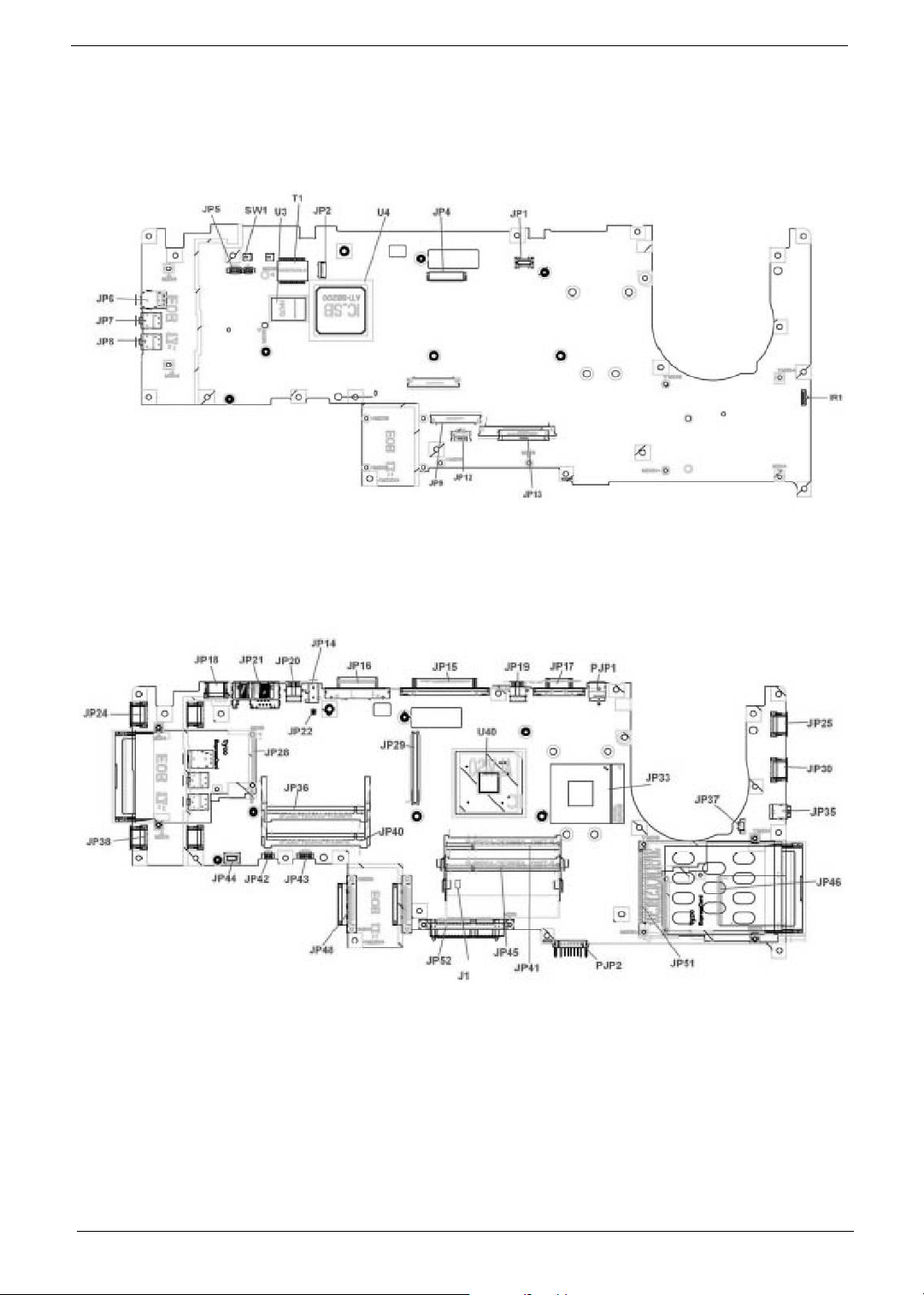
Mainboard Placement
Top View
Rear View
6
Page 13

ITEM DESCRIPTION ITEM DESCRIPTION
JP1 To Power/B Connector JP33 CPU Socket
JP2 Bluetooth Connector JP35 IEEE1394 Connector
JP4 LCD Connector JP36 MINIPCI Connector (WLAN)
JP5 Internal MIC Connector JP37 FAN Connector
JP6 Headphone/SPDIF Jack JP38 USB Connector
JP7 Line-In Jack JP40 MINIPCI Connector (TV-
Tuner)
JP8 MIC-In Jack JP41 DDRII SO-DIMM Socket
JP9 Internal K/B Connector JP42 Internal Subwoofer
Connector
JP12 T/P Board Connector JP43 Internal Speaker Connector
JP13 To LED/B Connector JP44 MDC Connector
JP14 RF-In Connector JP45 DDRII SO-DIMM Socket
JP15 Parallel Port Connector JP46 5 IN 1 Socket
JP16 DVI Connector JP48 ODD Connector
JP17 CRT Connector JP51 PCMCIA Socket
JP18 USB Connector JP52 HDD Connector (P-ATA)
JP19 TV-Out Connector PJP1 DC-IN Jack
JP20 AV-In Connector PJP2 Battery Connector
JP21 RJ11/RJ45 Connector SW1 Lid Switch
JP22 RF to TV-Tuner Connector U3 LAN Chip
JP24 USB Connector U4 South Bridge Chipset
JP25 USB Connector U40 North Bridge Chipset
JP28 Express Card Socket T1 LAN Transformer
JP29 VGA/B Connector IR1 FIR Module
JP30 USB Connector J1 Clear CMOS Jumper
Aspire 9500
Page 14
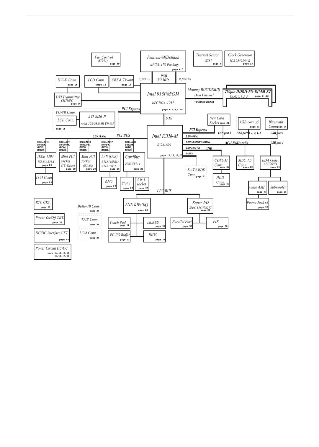
Block Diagram
Aspire 9500
Page 15
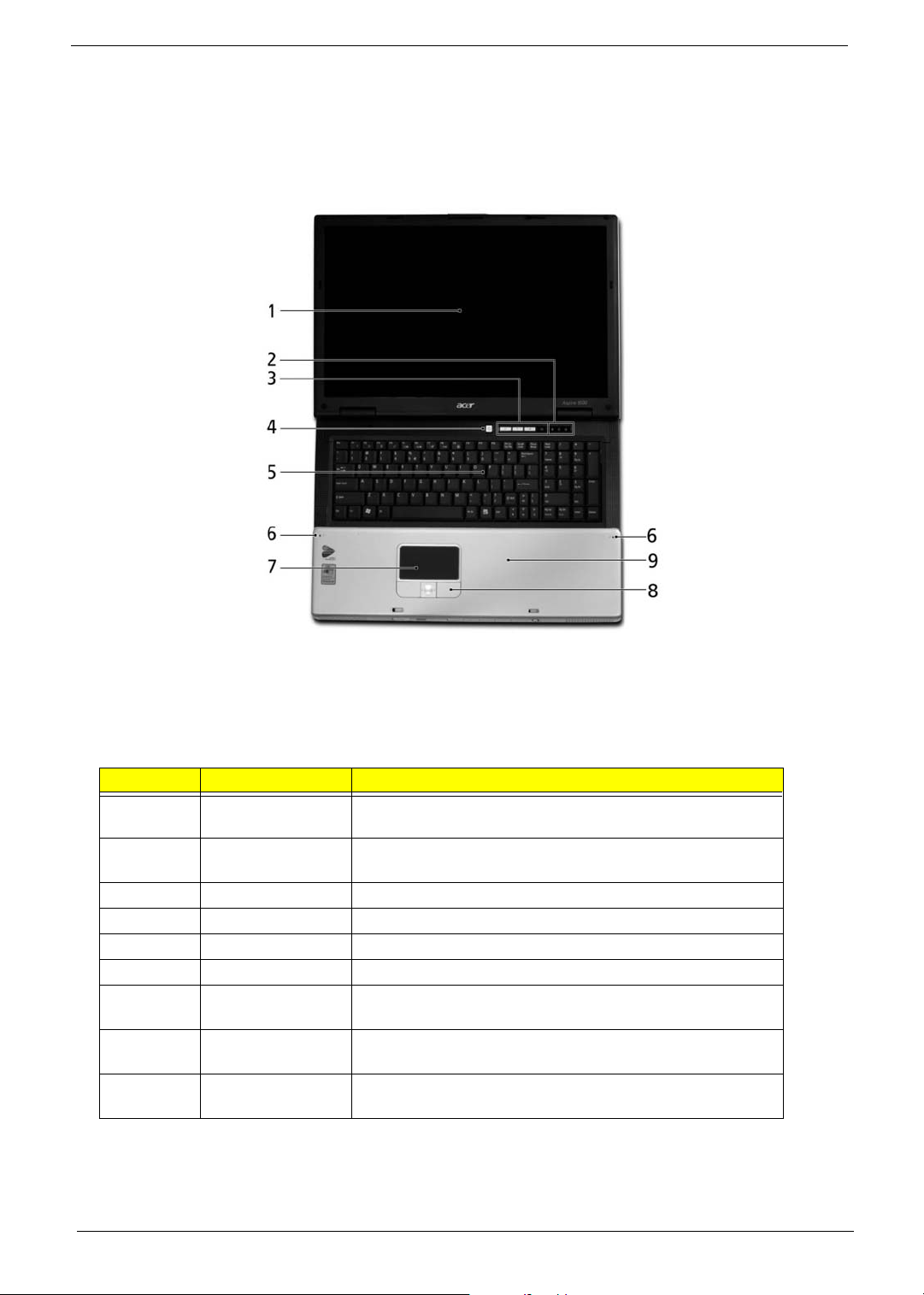
Outlook View
A general introduction of ports allow you to connect peripheral devices, as you would with a desktop PC.
Front View
10
# Item Description
1 Display screen Also called Liquid-Crystal Display (LCD), displays computer
output.
2 Status indicators Light-Emitting Diodes (LEDs) that light up to show the status
of the computer's functions and components.
3 Easy-launch buttons Buttons for launching frequently used programs.
4 Power button Turns the computer on and off.
5 Keyboard For entering data into your computer.
6 Microphones Internal microphones for stereo sound recording.
7 Touchpad Touch-sensitive pointing device which functions like a
computer mouse.
8 Click buttons (left,
center and right)
9 Palmrest Comfortable support area for your hands when you use the
The left and right buttons function like the left and right mouse
buttons; the center button serves as a 4-way scroll button.
computer.
Page 16
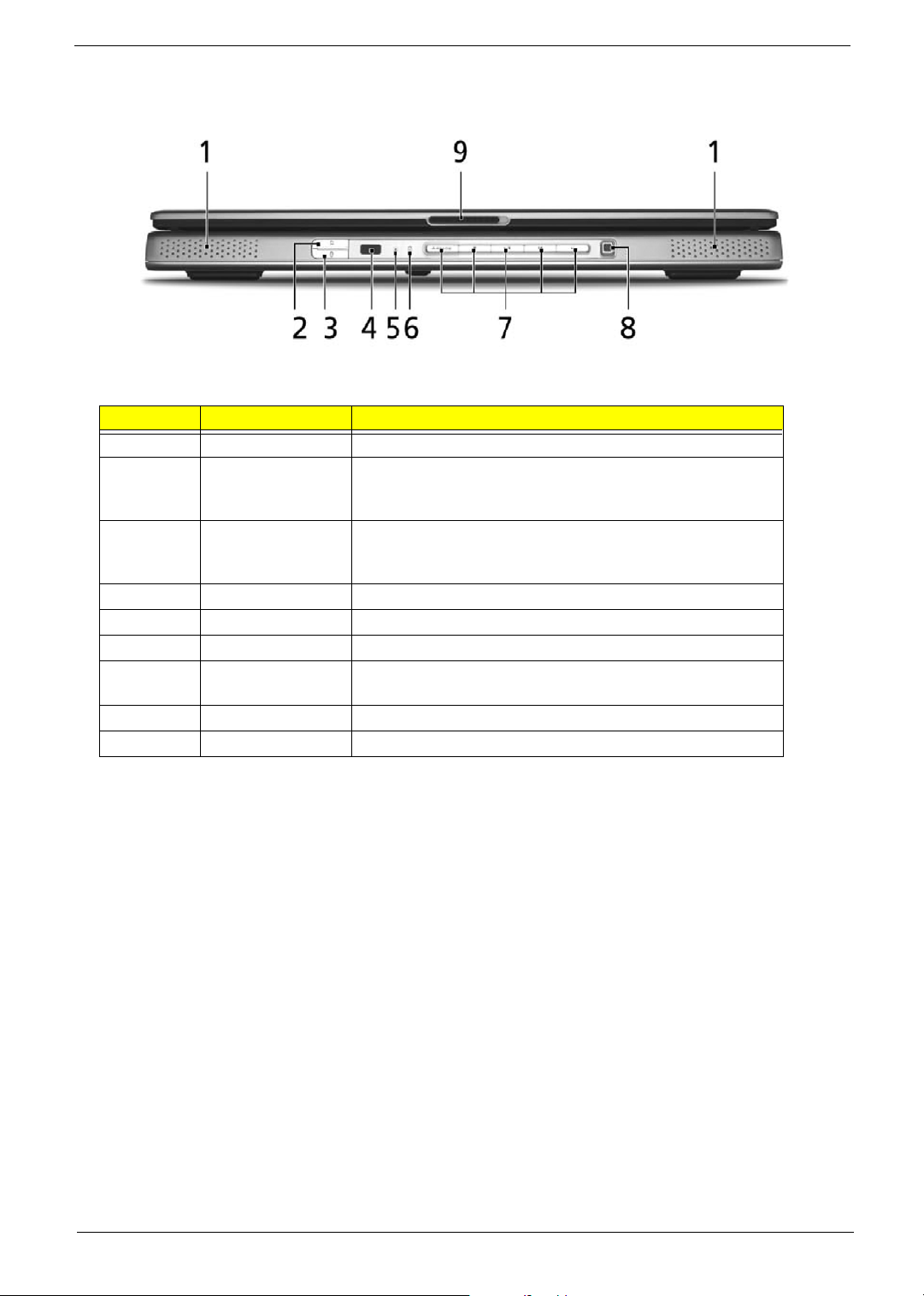
Closed Front Panel
# Item Description
1 Speakers Left and right speakers deliver stereo audio output.
2Wireless
communication
button/indicator
3 Bluetooth
communication
button/indicator
4 CIR receiver Receives signals from a remote control.
5 Power indicator Indicates the computer's power status.
6 Battery indicator Indicates the computer's batttery status.
7 Arcade/media
buttons
8 Media control Five-way multimedia button (for selected models).
9 Latch Locks and releases the lid.
Press to enable/disable the wireless function. Lights to
indicate the status of wireless LAN communication.
Press to enable/disable Bluetooth function. Lights to indicate
the status of Bluetooth communications.
For use with Acer Arcade and other media playing programs
(for selected models).
Aspire 9500
Page 17
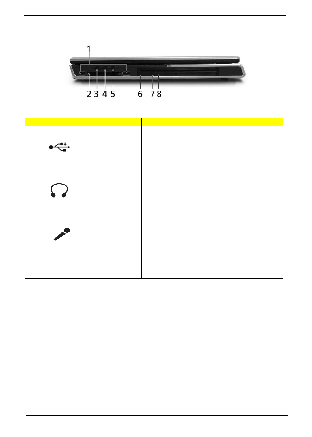
Left View
# Icon Item Description
1 USB 2.0 port USB 2.0 ports
2 Express Card PCI Express card slot Accepts one PCI Express card.
3 Headphone/speaker/line-
out & S/PDIF jack
Connects to audio line-out devices (e.g., speakers,
headphones), S/PDIF compatible
4 N/A Line-in jack Accepts audio line-in devices
5 Microphone jack Accepts input from external microphones.
6 N/A Slot-load optical drive Internal optical drive; accepts CDs or DVDs.
7 N/A Slot-load optical drive
eject button
8 N/A LED indicator Lights up when the optical drive is active.
Ejects the optical disk from the drive.
12
Page 18
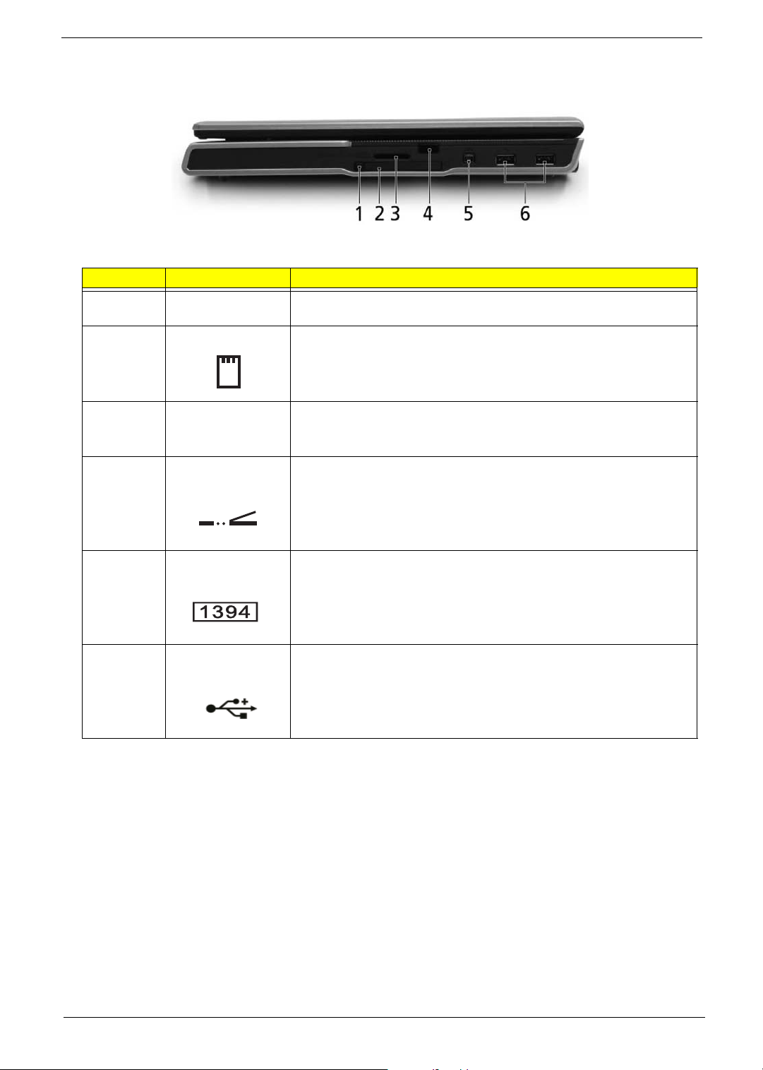
Right View
# Item Description
1 PC Card slot eject
2 PC card slot Accepts one Type II PC Card.
3 5-in-1 card reader Accepts Memory Stick, Memory Stick Pro, MultiMediaCard (MMC),
4 Infrared port Interfaces with infrared devices (e.g. infrared printer, IR-aware
Ejects the PC Card from the slot.
button
Secure Digital (SD), and xD-Picture Card.
computer, etc...)
3 IEEE 1394 Port Connects IEEE 1394 devices.
4 Two USB Ports Connect to USB 2.0 devices (e.g., USB mouse, USB camera).
Aspire 9500
Page 19
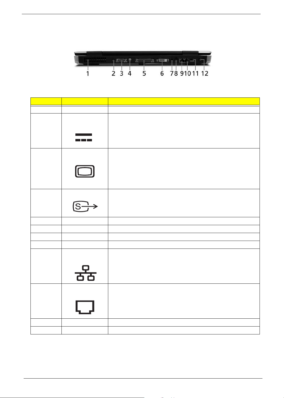
Rear View
# Item Description
1 Ventilation slots Enable the computer to stay cool, even after prolonged use.
2 DC-in jack Connects to an AC adapter.
3 External display
(VGA) port
4 S-video out port Connects to a television or display device supporting S-video input.
5 Parallel port Connects to a printer.
6 DVI-D port Supports digital video connections. (for selected models)
7 RF jack For digital and analog TV input (for selected models).
8 Audio/video in port Supports both audio and video input.(for selected models).
9 Network jack Connects the computer to the 10/100/1000 Ethernet network.
10 Modem Jack Connects the built-in fax/data modem to a phone line.
Connects to a display device (e.g., external monitor, LCD projector).
14
11 USB 2.0 port Connects to USB 2.0 devices (e.g., USB mouse, USB camera).
12 Kensington lock slot Connects to a Kensington-compatible computer security lock.
Page 20
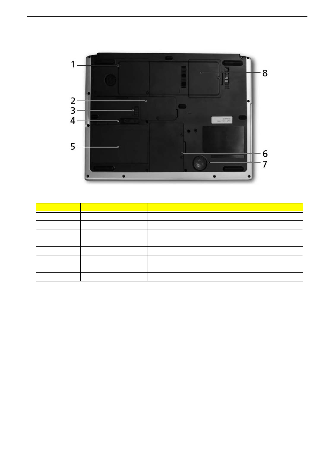
Base View
# Item Description
1 Cooling fan Helps keep the computer cool.
2 Memory compartment Houses the computer's main memory.
3 Battery lock latch Locks the battery in place.
4 Battery release latch Releases the battery for removal.
5 Battery bay Houses the computer's battery pack.
6 Hard disk bay Houses the computer's hard disk (secured by a screw).
7 Sub woofer Emits low frequency sound output.
8 PCI Card bay Houses the computer’s Mini PCI Card.
Aspire 9500
Page 21
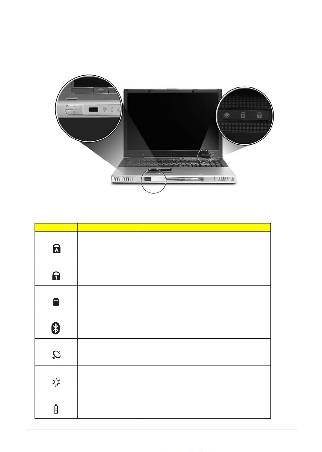
Indicators
"Launch keys" on page 10
"Launch keys" on page 10
"Launch keys" on page 10
"Launch keys" on page 10
Your computer provides an array of three indicators located above the keyboard, in addition to four
indicators positioned at the front of the palm rest area. These indicators show the status of the computer
and its componetns.
The three indicators located above the keyboard provide the following status information:
Icon Item Description
Caps Lock activity Lights when Caps Lock is activated.
Num Lock activiy Lights when Num Lock is activated.
Media activity Lights when the hard disk or optical drive is active.
Bluetooth Indicates the status of Bluetooth communication.
Wireless LAN Indicates the status of wireless LAN communication.
Power Lights up when the computer is on.
(Lights amber when in stand-by or sleep mode)
16
Battery Lights up when the battery is being charged.
Page 22
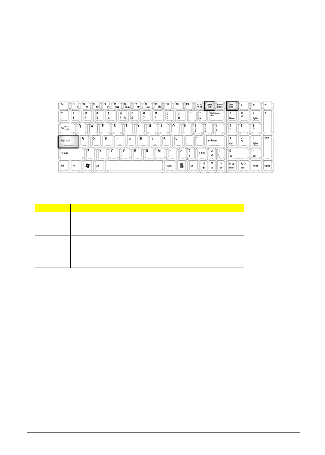
Keyboard
The keyboard features full-size keys with an embedded keypad, separated cursor keys, two Windows
keys, and twelve function keys (hot keys).
Special keys
Lock keys
The computer features three lock keys, each with its own status indicator light.
Lock Key Description
Caps Lock When Caps Lock is on, all alphabetic characters are typed in
uppercase. Toggle on and off by pressing the Caps Lock key on the left
side of the keyboard.
Num lock When Num Lock is on, the embedded numeric keyboard can be used.
Toggle on and off by pressing the Fn+tkeys simultaneously.
Scroll lock When Scroll Lock is on, the screen toggles up or down one line
at a time when the up and down cursor control keys are pressed.
NOTE: Scroll Lock doesn’t work in all applications. Toggle on and off by pressing the Fn+F12 keys
simultaneously.
Aspire 9500
Page 23
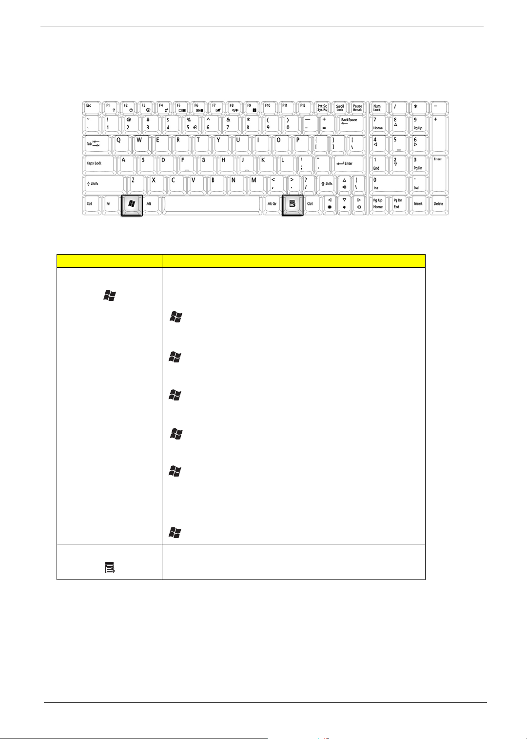
Windows Keys
The keyboard features two keys that perform Windows-specific functions.
Key Description
Windows logo key Pressed alone, this key has the same effect as clicking on the
Windows Start button; it launches the Start menu. It can also be
used with other keys to provide a variety of functions:
+ Tab (Activates the next Taskbar button)
+ E (Opens the My Computer window)
+ F1 (opens Help and Support)
+ F (opens the Find: All Files dialog box)
+ M (minimizes all windows)
j + Windows icon + M (undoes the minimize all windows
action)
+ R (opens the Run dialog box)
Application key This key has the same effect as clicking the right mouse button; it
opens the application’s context menu.
18
Page 24
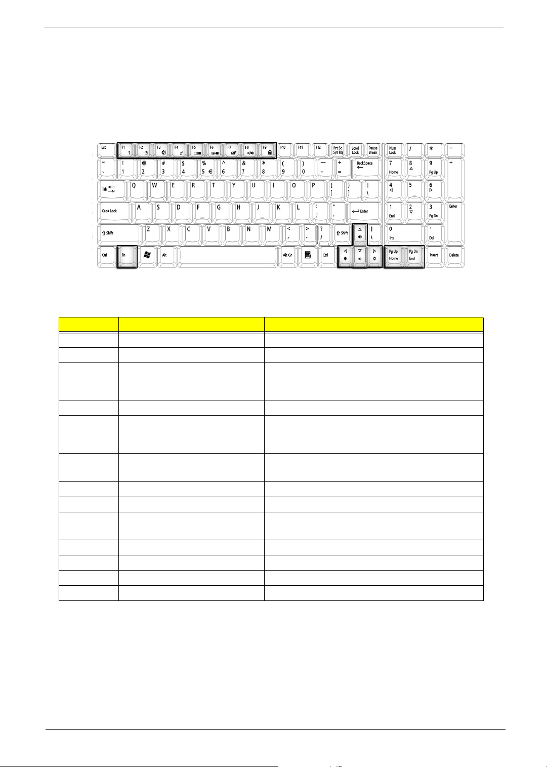
Function Keys
Using the Fn key with another key creates a hot key, providing a quick and convenient method for controlling
various functions.
To use a hot key, first hold down the Fn key. Next, press the second key in combination. Finally, release
both keys.
Your computer provides the following hot keys:
Hot Key Function Description
Fn+F1 Hot key help Displays help on hot keys
Fn+F2 Setup Access the computer’s configuration utility.
Fn+F3 Power management scheme
toggle
Fn+F4 Sleep Puts the computer in Sleep mode.
Fn+F5 Display toggle Switches display output between the display screen,
Fn+F6 Screen blank Turns the display screen backlight
Fn+F7 Touchpad toggle Turns the internal touchpad on and off.
Fn+F8 Speaker toggle Turns the speaker on and off.
Fn+Sub-
woofer key
Fn+w Volume up Increases the speaker volume.
Fn+y Volume down Decreases the speaker volume.
Fn+x Brightness up Increases the screen brightness.
Fn+z Brightness down Decreases the screen brightness.
Sub-woofer Turns the sub woofer on and off
Switches the power management scheme used by
the computer (function available if supported by
operating system).
external monitor ( if connected) and both the display
screen and external monitor.
off to save power. Press any key to return.
NOTE: When activating hotkeys, press and hold the Fn key before pressing the other key in the hotkey
combination.
Aspire 9500
Page 25
Fn F6
Fn F7
Fn F8
Fn
Fn
Fn
Fn
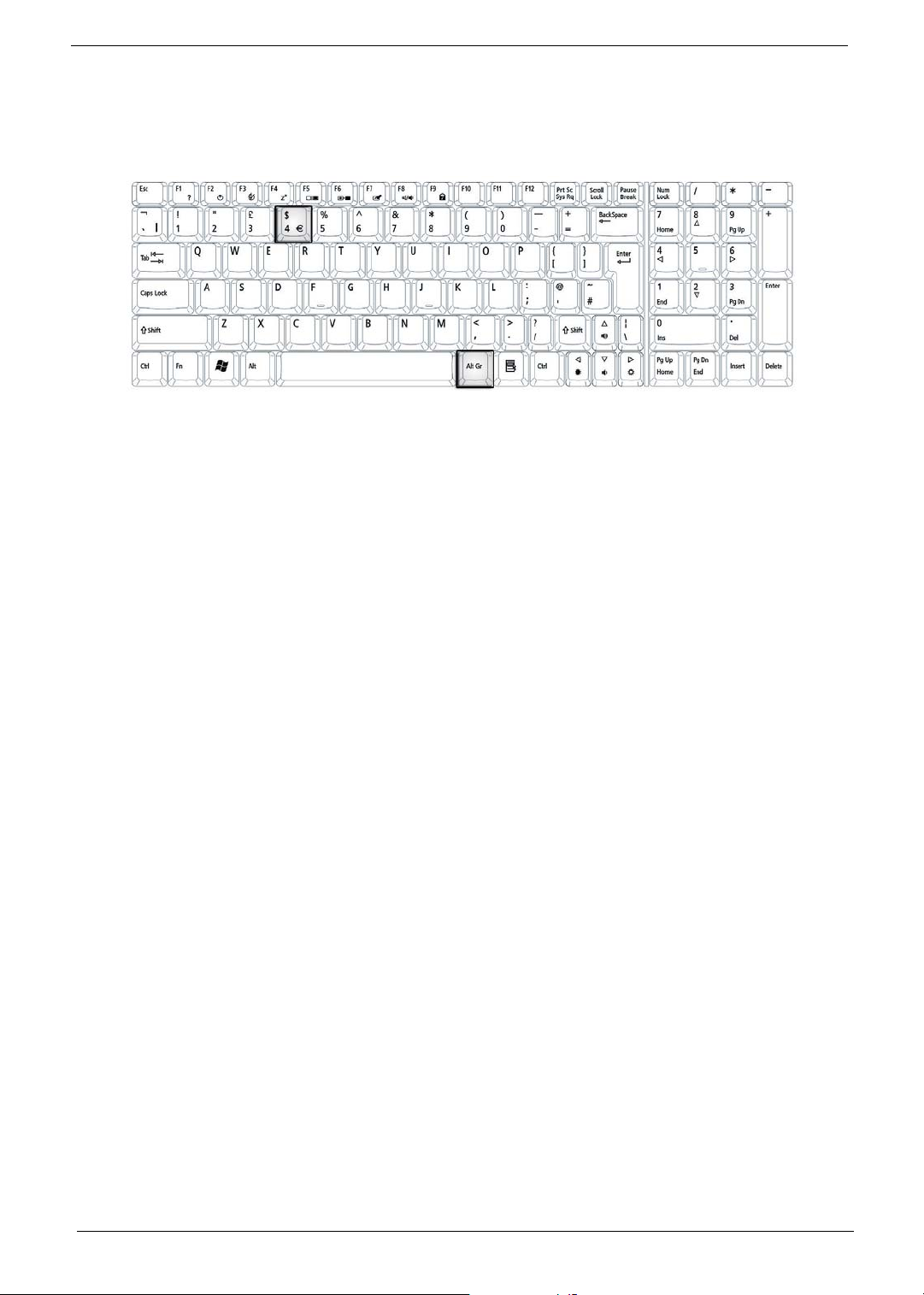
Euro key
Your computer supports the new Euro currency character. First, hold down the Alt Gr key, and then press the
Euro key.
20
Page 26
Touchpad
The build-in touchpad is a PS/2 compatible pointing device that senses movement on its surface.
The cursor responds to your finger movements on the touchpad. In addition, the two click buttons provide
the same functionality as a computer mouse, while the scroll key enables easy up and down scrolling in
documents and web pages.
The touchpad is located in the middle of the palm rest area, providing maximum comfort and efficiency.
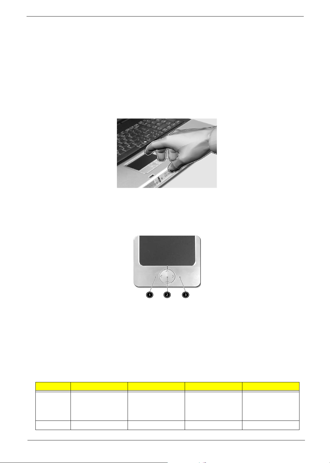
Touchpad Basics
Use the touchpad as follows:
T Slide your finger over the surface of the touchpad to control the movement of the cursor. Tap the
touchpad to perform selection and execution functions.
T Press the left (1) and right (3) buttons to perform selection and execution functions, just as you
would use the buttons on a computer mouse.
T Use the scroll key (2) to scroll through long documents and web pages. Press the top of the key to
scroll up, and the bottom to scroll down; left to scroll left, and right to scroll right.
Function Left Button Righ Button 4-Way Scroll Way Tap
Execute Click twice quickly Tap twice (at the
same speed as
double-clicking the
mouse button)
Select Click once Tap once
Aspire 9500
Page 27
Function Left Button Righ Button 4-Way Scroll Way Tap
Drag Click and hold.
Then slide your
finger across the
touchpad to drag
the cursor over the
selection.
Access
context
menu
Scroll Click and hold the
NOTE: Keep your fingers, as well as the surface of the touchpad dry and clean. The touchpad is sensitive to
your finger movements: the lighter the touch, the better the response. Tapping hard will not increase the
touchpad’s responsiveness.
Click once
up/down/left/right
button
Tap twice quickly.
On the second tap,
slide your finger
across the
touchpad to drag
the cursor over the
selection.
22
Page 28
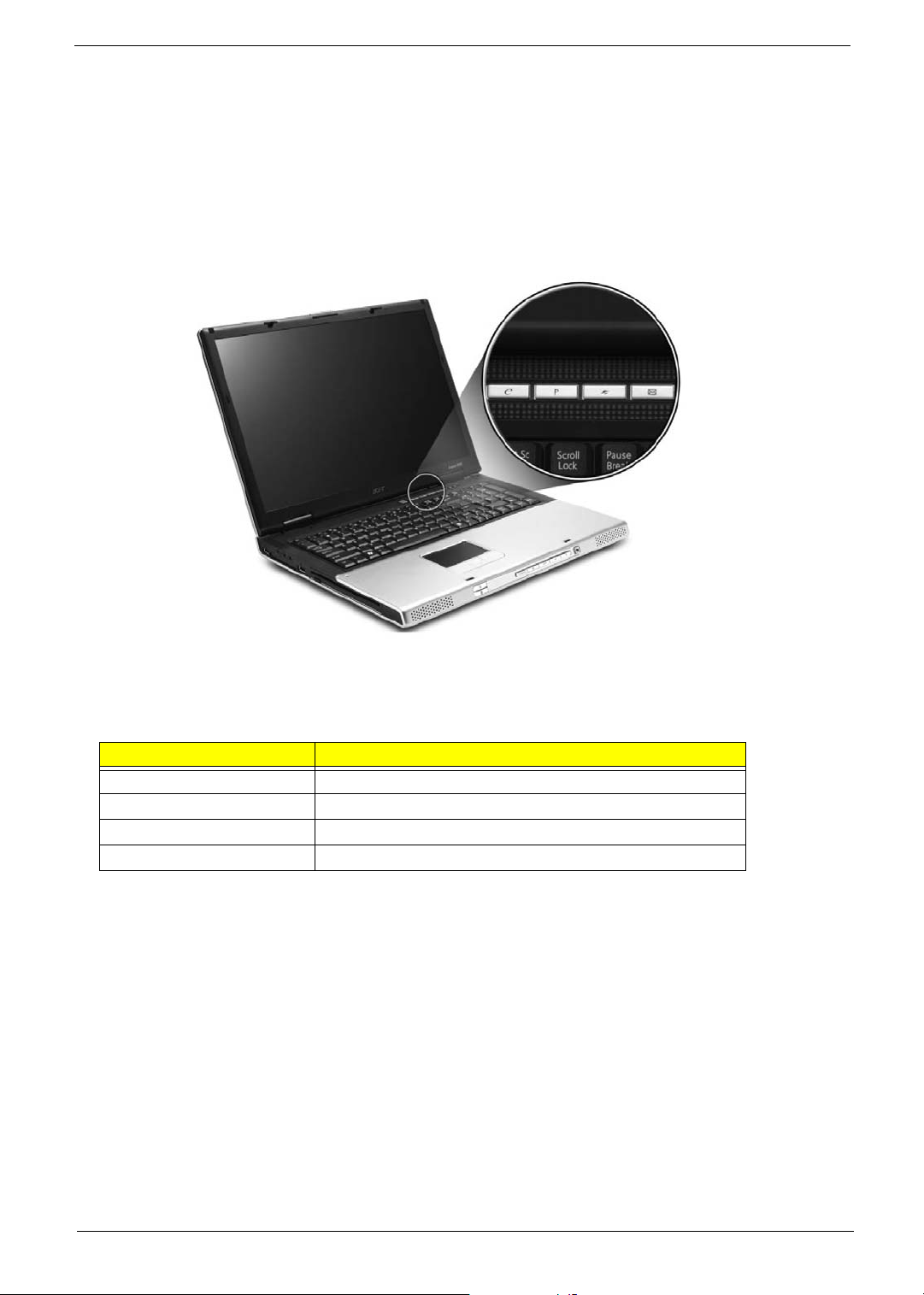
Launch Keys
Located at the top of the keyboard are four buttons, in addition to the power button. These buttons are
called launch keys. They are designed as key 1, key 2, key 3 and key 4, from right to left. By default,
key 1 is used to launch the email application and key 2 is used to launch the Internet browser. Key 3
and key 4 start the Launch Manager application. The first four launch keys can be set by the user. To set
the launch keys, run the Acer Launch Manager.
# Description
e Launches your email application.
P User-programmable
Web browser Internet browser application
Mail Email application
Aspire 9500
Page 29
Hardware Specifications and Configurations
Processor
Item Specification
CPU type Intel Pentium M 1.6G ~ 2.13G
CPU package 478pin
CPU core voltage Depend on VID
CPU I/O voltage 1.05V
BIOS
Item Specification
BIOS vendor Insyde
BIOS Version Insyde
BIOS ROM type Flash ROM
BIOS ROM size 512KB
BIOS package 32 lead of TSSOP
BIOS password control Set by setup manual
Second Level Cache
Item Specification
Cache controller Built-in CPU
Cache size 2MB
1st level cache control Always enabled
2nd level cache control Always enabled
Cache scheme control Always enabled
System Memory
Item Specification
Memory controller Intel 915PM/GM
Memory size 256MB/512MB/1GB
DIMM socket number 2 slots
Supports memory size per slot 1024MB
Supports maximum memory size 2GB (by two 1024MB SO-DIMM module)
Supports DIMM type DDR II DRAM
Supports DIMM Speed 400/533MHz
Supports DIMM voltage 1.8V
Supports DIMM package 200-pin SO-DIMM
Memory module combinations You can install memory modules in any combinations as long as
they match the above specifications.
24
Page 30
Memory Combinations
Slot 1 Slot 2 Total Memory
256/512MB/1024MB 0 MB 256MB/512MB/1024MB
256/512MB/1024MB 256MB 512MB/768MB/1280MB
256/512MB/1024MB 512MB 768MB/1024MB/1536MB
256/512MB/1024MB 1024MB 1280MB/1536MB/2048MB
NOTE: Above table lists some system memory configurations. You may combine DIMMs with various
capacities to form other combinations.
Sysetm Major Chip
Item Controller
System core logic Intel 915GM/PM + ICH6M
Super I/O controller SMSC 47N217, LPC interface
Audio controller Realtek ALC260D Codec
Video controller ATI M26P
Hard disk drive controller ICH6M
Keyboard controller ENE KB910Q
RTC ICH6M
LAN controller RTL8110SBL
IEEE 1394 controller TPA43AB21A
.
LAN Interface
Item Specification
Supports LAN protocol 1Gbps
LAN connector type RJ45
LAN connector location Rear Side
.
Modem / Bluethooth Interface
Item Specification
Data modem data baud rate (bps) 56K
Supports modem/bluetooth protocol V.90/V.92 HD Audio modem card (MDC)
Modem connector type RJ11
Modem connector location Rear Side
Hard Disk Drive Interface
Item Specification
Vendor &
Model
Name
Capacity
(MB)
HITACHI Moraga A
IC25N060ATMR04-0
SEAGATE N2
ST960821A
Toshiba Pluto
MK6025GAS
60000 80000 100000 100000
HITACHI Moraga A
IC25N060ATMR04-0
SEAGATE N2
ST9808210A
Toshiba Pluto
MK8025GAS
SEAGATE N2
ST9100822A
Toshiba Pluto
MK1031GAS
HITACHI Moraga+B
HTS541010G9AT00
SEAGATE
ST9100823A
Toshiba Aries-B
MK1032GAX
Aspire 9500
Page 31

Item Specification
Vendor & model name Panasonic Dual Slot-in UJ-845
Performance Specification CD-R/RW DVD-ROM/RW
Soft Read Error
Hard Read Error
Less than 10
Less than 10
-9
-12
Data Buffer Capacity 2 MBytes
Interface IDE (ATAPI Compliant)
Speed Reading :
24X Speed CD-ROM
Writing :
16X Speed CD-RW
24X Speed CD-R
Reading :
8X Speed DVD-ROM
Writing :
5X Speed DVD-RAM
8X Speed DVD-R
4X Speed DVD-RW
Applicable disc format DVD: DVD-ROM (DVD-5, DVD-9, DVD-10),
DVD-R (3.95G/4.7G),
DVD-RAM (2.6G/4.7G),
DVD-RW
CD: CD-Audio,
CD-ROM(mode 1 and mode 2),
CD-ROM XA ( mode2, form 1 and form 2),
CD-RW
Photo CD
Video CD
Enhanced Music CD
CD-TEXT
Power Requirement
Input Voltage +5 V +/- 5 %
26
Page 32

Item Specification
Vendor & model name Panasonic Tray UJDA-770
Performance Specification CD-R/RW DVD-ROM/RW
Soft Read Error
Hard Read Error
Less than 10
Less than 10
-9
-12
Data Buffer Capacity 2 MBytes
Interface IDE (ATAPI Compliant)
Speed Reading :
Max 24X CAV CD-R
Writing :
Reading :
MAX 8X CAV (MAX 10800 kB/s) DVDROM
Max24X Zone CLV CD-R
4X CLV CD-RW
Applicable disc format DVD: DVD-ROM
DVD-R, DVD-RW(Ver. 1.1)
DVD-RAM(2.6GB, 4.7GB)
DVD+R, DVD+RW
CD: CD-DA,CD-ROM,CD-ROM XA
CD-R,CD-RW
PhotoCD(muiltiSession),Video CD
CD-Extra(CD+),CD-text
Power Requirement
Input Voltage +5 V +/- 5 %
Item Specification
Vendor & model name Pioneer DVR-K05RV
Performance Specification CD-R/RW DVD-ROM/RW
Soft Read Error
Hard Read Error
Less than 10
Less than 10
-9
-12
Data Buffer Capacity 2 MBytes
Interface IDE (ATAPI Compliant)
Speed Reading :
24X CAV at CD-ROM and CD-R / RW
Writing :
24X CAV atCD-R
24X Zone CLV at CD-RW
Reading :
8XCAV at DVD-ROM (Single Layer) &
DVD-R / RW or+R/RW
6X CAV at DVD-ROM (Dual Layer) &
DVD-R-DLor +R-DL
2X Zone CLV at DVD-RAM
Writing :
8X CAV at DVD-R or +R
8X Zone CLV at DVD+RW
6X Zone CLV at DVD-RW
4X Zone CLV at DVD-R-DL (Dual
Layer)or +R-DL (Double Layer)
Aspire 9500
Page 33

Item Specification
Applicable disc format KODAK Photo CD Single and Multi-session
CD Extra (CD PLUS)
Video CD
CD text data (Read / Write)
CD-R discs (Read / Write)
CD-RW discs (Read / Write)
DVD-ROM
DVD-R Ver.2.00 for General (Read / Write)
DVD-R-DL (Read/Write)
DVD-RW Ver.1.0 & 1.1 & 1.2 (Read / Write)
+R Ver.1.0 & 1.11& 1.2 (Read/Write)
+R -DL Ver1.0 (Read / Write)
+RW Ver.1.1 & 1.2 (Read/Write)
DVD-RAM (Ver.2.0 & 2.1) (Read only)
Power Requirement
Input Voltage +5 V +/- 5 %
Audio
Item Specification
Audio Controller Realtek ALC 260D
Audio onboard or optional Built-in
Mono or Stereo Stereo
Resolution 20 bit stereo Digital to analog converter
18 bit stereo Analog to Ditial converter
Compatibility Microsoft PC99/2100, AC97 2.3 & WHQL/WLP2.0
Mixed sound source CD
Sampling rate 96 KHz
Internal microphone No
Internal speaker / Quantity Yes / 2
28
Page 34

Hard Disk Drive Interface
Item Specification
Bytes per
512 512 512 512
sector
Data heads 3/3/4 4/4/4 4/4/4 4/4/4
Drive Format
Disks 2/2/2 2/2/2 2/2/2 2/2/2
Spindle
4200 RPM 4200 RPM 4200 RPM 4200 RPM
speed
(RPM)
Performance Specifications
Buffer size 8192KB 8192KB 8192KB 8192KB/8192KB/
16384KB
Interface ATA-6 ATA-6 ATA-6 ATA-6
Max. media
350Mb/s 350Mb/s 350Mb/s 493Mb/s
transfer rate
(disk-buffer,
Mbytes/s)
Data
transfer rate
100 MB/Sec.
Ultra DMA mode-5
100 MB/Sec.
Ultra DMA mode-5
100 MB/Sec.
Ultra DMA mode-5
100 MB/Sec.
Ultra DMA mode-5
(host~buffer
, Mbytes/s)
DC Power Requirements
Voltage
5V(DC) +/- 5% 5V(DC) +/- 5% 5V(DC) +/- 5% 5V(DC) +/- 5%
tolerance
Optical Drive Interface
Item Specification
Vendor & model name Panasonic Combo SLOT-IN CW 8124
Performance Specification CD-R/RW DVD-ROM
Soft Read Error
Hard Read Error
Less than 10
Less than 10
-9
-12
Data Buffer Capacity 2 MBytes
Interface IDE (ATAPI Compliant)
Speed Reading :
24x speed CD-ROM
Writing :
24x speed CD-R
Reading :
8x speed DVD-ROM
DVD MULTI Read Support
24x speed CD-RW writing
Aspire 9500
Page 35

Optical Drive Interface
Item Specification
Applicable disc format DVD: DVD-ROM (DVD-5, DVD-9, DVD-10),
DVD-R (3.95G/4.7G),
DVD-RAM (4.7G),
DVD-RW
CD: CD-Audio,
CD-ROM(mode 1 and mode 2),
CD-ROM XA ( mode2, form 1 and form 2),
CD-RW
Photo CD
Video CD
Enhanced Music CD
CD-TEXT
Power Requirement
Input Voltage +5 V +/- 5 %
Video Interface
Item Specification
Video vendor ATI
Video name M26P
Chip voltage Core/1.2V, 1.5V
Supports ZV (Zoomed Video) port No
Video Resolution Mode (for both LCD and CRT)
Resolution 16 bits (High color) 32 bits (True color)
1440*900 (WXGA) Yes Yes
1680*1050(WSXGA+) Yes Yes
USB Port
Item Specification
USB compliancy level 2.0
OHCI USB 2.0
Number of USB port 5
Location Rear side x1
Left side x 2
Right side x2
PCMCIA Port
Item Specification
PCMCIA controller ENE CB714 CardBus
Supports card type Type II
Number of slots One type-II
Access location Left Side
Supports ZV (Zoomed Video) port No
Supports 32 bit CardBus Yes
30
Page 36

Keyboard
Item Specification
Keyboard Controller ENE KB910Q
Total Number of Keypads 103 keys with 12 function keys
Function Keys
Easy-Launch Buttons
Two Front-Access LED Buttons
T Four cursor keys
T Two Windows keys
T Hotkey controls
T Embedded numeric keypad
T International language support
T Internet
T Email
T Empowering button
T User-programmable button
T WLAN
T Bluetooth
Windows logo key Yes
Internal & external keyboard work
Yes
simultaneously
Battery
Item Specification
Vendor & model name Sony/Sanyo
Battery Type Li-ion
Pack capacity 60Wh
Cell voltage 3.7V/cell/2000mAh High discharge rate
Number of battery cell 8
Package configuration
Pin 1
BATT+: Battery+, Battery Positive Terminal
Pin 2
Pin 3 ID : Identify Pin (Note 1)
Pin 4 B/I : Battery-In Pin
Pin 5 TS : Connect to Thermister
Pin 6 SMD : SMBus data interface I/O pin
Pin 7 SMC : SMBus clock interface I/O pin
Pin 8
GND : Battery Negative Terminal
Pin 9
NOTE: 1. Li-ion Battery: Connect 1K % ohm resistor to GND in Battery PCB.
5±
NOTE: B/I pin: Battery can be Charged/Discharged only while this pin is connected to GND.
Aspire 9500
Page 37

LCD Inverter Specification
No. Panel Model Type
1 Samsung LTN170WP-L02-0 17"
WSXGA+
Frequency
(KHz)
40/60/65 4/6/6.5 1950 Vrms 730 Vrms
Current
(mA)
VS at 0 C
°
Work
Voltage
at 6mA
2 Samsung LTN170WX-L05-E 17" WXGA 40/60/65 3/6/6.8 1690 Vrms 730 Vrms
at 6mA
3 LG LP171WP5-TL03 17" WXGA 40/60/70 3/6/6.5 1500 Vrms 760 Vrms
at 6mA
4 LG LP171WX2-A4K5 17" WXGA 40/60/70 3/6.5/6.8 1500 Vrms 735 Vrms
at 6.5mA
5 AUO B170PW01 V.1 17" WXGA 40/50/80 3/6.5/7 1500 Vrms 815 Vrms
at 6.5mA
6 QDI QD17TL02-02 17" WXGA 50/TBD/60 3/6/6.5 1660 Vrms 724 Vrms
at 6.5mA
LCD
Item Specification
Vendor &
model name
Samsung
LTN170W
P-L02-0
Samsung
LTN170W
X-L05-E
LG
LP171WP
5-TL03
LG
LP171WX
2-A4K5
AUO
B170PW0
1 V.1
QDI
QD17TL0
2-02
Mechanical Specifications
LCD display
17” 17” 17” 17” 17” 17”
area
(diagonal,
inch)
Display
TFT TFT TFT TFT TFT TFT
technology
Resolution
WSXGA
(1440*900)
WXGA
(1440*900)
WXGA
(1440*900)
WXGA
(1440*900)
WXGA
(1440*900)
WXGA
(1440*900)
Brightness
155/180
175/200
420/500
200(typ.)
170/200
175/200
Supports
262K 262K 262K 262K 262K 262K
colors
Optical Specification
Brightness
control
Contrast
keyboard
hotkey
keyboard
hotkey
keyboard
hotkey
No No No No No No
control
Suspend/
Yes Ye s Yes Ye s Yes Ye s
Standby
control
AC Adapter
Item Specification
Vendor & model name Delta 90W ADP-90SB BBAC
Lite-On 90W PA1900-04 AC
32
keyboard
hotkey
keyboard
hotkey
keyboard
hotkey
Page 38

AC Adapter
Item Specification
Input Requirements
Maximum input current (A,
@100Vac, full load)
Nominal frequency (Hz) 47 - 63
Frequency variation range
(Hz)
Nominal voltages (Vrms) 90 - 264
Inrush current The maximum inrush current will be less than 50A and 100A when
Efficiency High efficiency 85% minimum, at 100~240Vac AC input, full load,
Output Ratings (CV mode)
DC output voltage Offers constant voltage 19.0V output source with 150W max output
Noise + Ripple 300mvp-pmax (20MHz bandwidth) for resistor load
Output current 0 A (min.) 3.5A (max.)
Output Ratings (CC mode)
DC output voltage 18.0 ~ 20.0
Constant output 7.74A
Dynamic Output Characteristics
Start-up time 3 sec. (@115 Vac and 230Vac full load)
Hold up time 5ms min. (@115 Vac input, full load)
Over Voltage Protection
(OVP)
Short circuit protection Output can be shorted without damage, and auto recovery
Electrostatic discharge
(ESD)
Dielectric Withstand Voltage
Primary to secondary 4242 Vdc for 1 second-
Leakage current 60uA at 240Vac/60Hz
Regulatory Requirements 1. FCC class B requirements (USA)
1.8A max@3.5A/100Vac and 240 Vac
47 - 63
the adapter is connected to 100Vac(60Hz) and 240Vac(50Hz)
respectively.
warm-up condition.
power capacity.
25V
15kV (at air discharge)
8kV (at contact discharge)
2. VDE class B requirements (German)
3. VCCI classII requirements (Japan)
Power Management
ACPI Mode Power Management
Mech. Off (G3) All devices in the system are turned off completely.
Soft Off (G2/S5) OS initiated shutdown. All devices in the system are turned
off completely.
Working (G0/S0) Individual devices such as the CPU and hard disk may be
power managed in this state.
Aspire 9500
Page 39

Power Management
ACPI Mode Power Management
Sleeping State (S3) CPU Power Down
VGA Power Down
PCMCIA Suspend
Audio Power Down
Hard Disk Power Down
Super I/O Power Down
Sleeping State (S4) Also called Hibernate state. System saves all system
states and data onto the disk prior to power off the whole
system.
Environmental Requirements
Item Specification
Temperature
Operating +5 ~ +35°C
Non-operating -20 ~ +65°C (storage package)
Humidity
Operating 10% ~ 90% without condensation
Altitude Operating sea level 0 to 10,000ft
Storage sea level 0 to 40,000ft
Mechanical Specification
Item Specification
Dimensions 15.83” x 11.26” x1.2”
402(W)mm x 286(D)mm x 35/37(H) mm
Weight 3.6 kg with single lamp LCD module
3.7 kg with dual lamp LCD module
34
Page 40

Mechanical Specification
Item Specification
I/O Ports
T Five USB 2.0 ports
T IEEE 1394 port
T Ethernet (RJ-45) port
T Modem (RJ-11) port
T External display (VGA) port
T S-video/TV-out (NTSC/PAL) port
T DVI-D port
T Parallel port
T Microphone-in jack
T Line-in jack
T Headphones/Speaker/Line-out/SPDIF port
T Infrared (FIR) port
T CIR (at the front side)
T Type II PC Card slot
T AV-in (7-pin) port (MFG option)
T RF input for digital TV and analog TV (MFG option)
T 5-in-1 card reader (MS/MS-Pro/ MMC/ SD/xD-Picture card
T DC-in jack for AC adaptor
T Express Card
Drive Bays One
Material Recycle plastic PC+ABS 94V0
Media Console
T Arcade button
T Stop button
T Play/Pause button
T Fast Forward
T Rewind
T 5-way Switch
TM
)
Aspire 9500
Page 41

Jumper Board
VGA Board
Item Description
JP1 To LCD Connector
JP2 To M/B Connector
U4 VGA Chip
U3,U5,U6,U7 Graphic Memory
36
Page 42

Power Board
Item Description Item Description
SW1 Power Button D1 Power LED
SW2 Empowering Button D2 E-Mail LED
SW3 User Button 1 D3 Media LED
SW4 Internet Button D4 Caps Lock LED
SW5 E-Mail Button D5 Num Lock LED
Touchpad Board
Item Description Item Description
SW1 Scroll-up Button SW4 Scroll-down Button
SW2 Scroll-left Button SW5 Left Button
SW3 Scroll-right Button SW6 Right Button
Aspire 9500
Page 43

LED Board
Item Description Item Description
SW1 WLAN ON/OFF Button D4 Suspend LED
SW2 Bluetooth ON/OFF Button D5 Battery Discharge LED
D1 WLAN LED D6 Battery Charge LED
D2 Bluetooth LED IR1 CIR Module
D3 POWER LED
Media Board
38
Item Description Item Description
SW1 WLAN ON/OFF Button D4 Suspend LED
SW2 Bluetooth ON/OFF Button D5 Battery Discharge LED
SW3 ARCADE Button D6 Battery Charge LED
SW4 PLAY/PAUSE Button D7 ARCADE LED
SW5 STOP Button D8 ARCADE ON LED
SW6 REV Button D9 LED
SW7 FWD Button D10 LED
SW8 5-Way Button D11 LED
D1 Bluetooth LED D12 LED
D2 WLAN LED IR1 CIR Module
D3 POWER LED
Page 44

Clear CMOS Jumper
J1 : Clear CMOS JUMPER
Aspire 9500
Page 45

Chapter 2
System Utilities
BIOS Setup Utility
The BIOS Setup Utility is a hardware configuration program built into your computer’s BIOS (Basic Input/
Output System).
Your computer is already properly configured and optimized, and you do not need to run this utility. However,
if you encounter configuration problems, you may need to run Setup. Please also refer to Chapter 4
Troubleshooting when problem arises.
To activate the BIOS Utility, press
on the bottom of screen).
The setup screen displays BIOS as follows:Navigating the BIOS Utility
Function Item
Information Display the system informations
Main Allows the user to specify standard IBM PC AT
Advanced Provides advanced settings of the system
Security Provides security settings of the system
Boot Allows the user to specify the boot options
Exit Allows the user to save CMOS setting and exit Setup
During setup,all Fn function keys and power saving functions are disabled.
There are five menu options: Main, Advanced, Security, Boot and Exit.
m during POST (when “Press <F2> to enter “Setup” message is prompted
system parameters
Chapter 2 40
Page 46

System Controls
Hot Keys
All Fn Key will support Sticky key mode.
Hot Key Function Description
Fn + F1 Hot key Help Menu This key will cause a help message to appear on the
Fn + F2 Launch Acer eSettings This key will launch Acer eManager->eSetting
Fn+ F3 Launch Acer ePM It will launch Acer ePowerManagement.
Fn + F4 SleepButton in ACPI mode In ACPI mode, the OS provides two buttons for sleep
Fn + F5 Launch Display Mode Menu (DMM) Follow DMM Specification except in OS other than 32-bit
Fn + F6 Display blank (backlight off) This key will cause the LCD back light to be turned off. This
Fn + F7 Touchpad On/Off This key will cause the internal touchpad pointing device to
Fn + F8 Speaker On/Off This key will cause the audio output to the speakers to
Fn + F9 Launch arcade Launch the multimedia application that supports DVD
Fn +w Volume up These keys will cause the volume of the audio chip to be
Fn +y Volume down
Fn +x Brightness up These keys can increase or decrease the brightness of the
Fn +z Brightness down
Alt + F10 Enter D2D recovery during POST
Launch Acer eRecovery in OS
display device that describes the definition and functionality
of the unit hot keys. It is preferred to have the key activate a
graphical display.
function. One is the Power On button and the other is the
Sleep Button. “Fn+F4” is assigned as the Sleep button in
ACPI mode. User can set the action of the Sleep Button on
the Power Management property.
Windows
provides both a quick security feature and some power
savings. The LCD back light can also be turned off via an
APM timer. The LCD back light will be turned on again
when any of the following events occur:
1. Any key pressed
2. Pointing device movement
USB device does not need to support.
be disabled/enabled . This is to prevent accidental system
wake-ups from standby. Pressing this key a second time
will re-enable the touch pad pointing device. BIOS check
Internal AuxDev if not exist then BIOS empty return.
muted or disabled. Pressing this key a second time will reenable the audio output to the speakers.
player, CD player, picture explorer, TV turner and MP3
player.
increased or decreased.When the hotkeys are pressed and
the volume are changing then system will pop one volume
status menu to show the status. This function should be
handled bythe system Volume utility within the each key
makes.
LCD back light. This function should be handled by the
Analog function within the keyboard controller (KBC).
Brightness will step up/down one unit as each time these
keys are pressed.
Enter D2D recovery during POST
Launch Acer eRecovery in OS
Euro, and USD dollar key: Under different language OS, user is able to input Euro dollar sign,and USD dollar
sign when word processing.
41 Chapter 2
Page 47

Buttons
Application Launch Buttons
Launch Keys Description
Launch Button P <Launch manager>
Launch Button e <Launch eManager>
Specific Keys
Wireless Button Wireless enable/disable
E-mail Button Launch Outlook Express
Bluetooth Button Enable/disable bluetooth
Internet Button Launch Internet Explorer
NOTE: Detail description and definition of application Launch Buttons, please reference the External spec.
Wireless LAN & Bluetooth Default Setting
Wireless LAN Bluetooth
After loading default settings in BIOS ON OFF
At Logon Screen Follows user setting in previous OS session
(by ePM or Launch Manager)
In OS Controlled by ePM or Launch Manager. Controlled by ePM or Launch
Follows user setting inprevious
OS session (by ePM or Launch
Manager).
Manager.
Power Button
The activity of the power button is as follows:
T If power button is pressed for less than 1 second then nothing happens.
T If power button is pressed for more than 1 second but less than 4 seconds then system would execute
User Requested OFF before the system entered into OS.
T If power button is pressed for more than 4 seconds then the notebook will be powered off by power button
over-ride feature.
T If OS is running in ACPI mode, the power button acts as the sleep button, and let OS controls the policy of
power button which is defined in Power Option under the OS.
Power Button Over-ride
Holding down the Power Button for 4 seconds will cause an unconditional transfer to the Off state without
notifying the operating system.
If press power button for less than 4 seconds, the system will enter suspend to RAM or OFF state according to
OS power option setting.
Lid Switch
This section describes the expected behavior of the system when the lid is opened or closed by the user.
If the system is running under legacy mode:
T Closing the lid will turn off LCD backlight.
If the system is running under ACPI mode:
T The operating system will determine what action to take when the lid is closed. (Windows does not define
Lid Open action in Power Option control panel)
T The function of lid close will follow the OS setting in power management (Nothing, standby, Hibernate or
Chapter 2 42
Page 48

Power off). However, if the setting is nothing, the backlight must still be turned off when the lid is closed.
T Lid Open action does not resume the system from S3, S4, and S5.
Hard Disk Password Function/ Password on boot function
This feature allows the user to set the password to prevent any unauthorized access to the internal hard disk.
T If the original HDD come from other machine with password protected, the system just show ” Enter HDD
password [ ]”
User is required to enter HDD password when system boot up.
T If user enter the wrong password, it will pop out message “Setup Warning, Invalid Passwrod”.....
T If the password is correct, system will continue to boot up into OS.
T "Password on boot"
T Password on boot is "Disabled", the system will NOT POP any password prompt windows during POST.
T If Password on boot is set to “Enabled” , the system will POP “Enter password” prompt windows during
POST. No matter the user key in "Supervisor Password" or "User Password", the system will be unlocked.
Valid Password Characters
Valid Password Characters:
Symbol Character Symbol Name
A-Z Alphabets A through Z (Not Case Sensitive)
0-9 Numerical Characters
-Dash
= Equal Sign
[ Left Bracket
] Right Bracket
.Period
, Comma
;Semi-Colon
/Slash
\ Back-slash
43 Chapter 2
Page 49

Information
Insyde Software SCU May 20, 2003 5:40:09 AM
Main Advanced Security Boot Exit
----Devices--------------------------------------------------- -----System------------------------Product Name = Aspire 9500
Manufacture Name = Acer
BIOS Version = V1.00
VGA Version = 3104
HDD Model Name = HITACHI_DK23EA-40-(PM)
HDD Serial Number = 123456789
ATAPI Model Name = UJDA740 DVD/CDROM-(SM)
Serial Number = ( 32 bytes)
CPU = Intel® Pentium ® 4
CPU speed = 2.0 GHz
L2 Cache = 2048 KB
----Memory------------------------
System Memory = 640 KB
Extended Memory = 256MB
VGA Memory = 128 MB
Asset Tag Number = (32 bytes)
UUID = (16 bytes)
Setup system date, time. Enable boot logo and get system information.
Parameter Description
Product Name This field will show the product name
Manufacture Name This field will show manufacturer name
BIOS Version This field reports the BIOS version of system
VGA Version This field reports the VGA version of the system
HDD Model Name This item will show the Model name of HDD installed on Primary IDE
master. The hard disk model name is automatically detected by the
system. If there is no hard disk present or unknown type, “None”
should be shown on the field.
HDD Serial Number This item will show the Serial number of HDD installed on Primary IDE
master. If no Hard disk or other devices are installed on Primary IDE
master, then it will display a blank line
ATAPI Model Name This field shows the ATAPI Model Name for you
Serial Number This item will show the Serial number of system
Asset Tag This item will show the Asset Tag number of the system
UUID This will be visible only when there is an internal LAN device present
System Memory This field reports the memory size of system base memory. The size is
fixed to 640KB.
Extended Memory This field reports the memory size of the extended memory in the
system.
Extended Memory size = Total memory size - 1 MB
Chapter 2 44
Page 50

Parameter Description
Video Memory VGA Memory size :
Discrete = 64 or 128MB (depends on actual VRAM size)
TurboCache = 32MB (actual TurboCache VRAM size)
Intel 915 DVMT: selectable between the following:
1. 64MB (8MB pre-allocated + 56MB DVMT)
2. 128MB (8MB pre-allocated + 128DVMT). This is the default
value.
3. Max DVMT (160MB on 256MB system memory, 224MB on
512MB and above system memory).
45 Chapter 2
Page 51

Main
This menu provides you the information of the system.the is
Insyde Software SCU May 20, 2003 5:40:09 AM
Main Advanced Security Boot Exit
Date and Time
ˣ˸ʳˢʳ˗˼˿˴ʳ
ԩ Quiet Boot
ԩ LCD Auto DIM
˲ Network Boot
˲ʳ ʳ F12 Boot Menu
ԩ D2D Recoveryʳ
Press <Tab> key to select a control. <OK> button or <Enter> key accept
entries. <Cancel> button or <Esc> key reject entries. Use cursor, spacebar,
and numeric keys to change values. <Alt> key activates accelerators.
----------------Power On Display---------------
( ) Auto
( ) Both
OK Cancel
Insyde Software SCU May 20, 2003 5:40:09 AM
Main Advanced Security Boot Exit
Date and Time
ʳ ʳ ˣ˸ʳˢʳ˗˼˿˴ʳ
ԩ Quiet Boot
ԩ LCD Auto DIM
˲ Network Boot
˲ʳ ʳ F12 Boot Menu
ԩ D2D Recoveryʳ
Enable or disable the F12 key for Boot Menu during POST
<Space> for select
Chapter 2 46
Page 52

Parameter Description Option
Date and Time The hours are displayed with 12 hour format. The values set in these two
Power On Display AUTO: if select “AUTO” item will let BIOS to select either one Display on
Quiet Boot Enabled: Customer Logo is displayed, and Summary Screen is disabled
Network Boot When this is selected, Boot from LAN feature is enabled. When this is not
LCD Auto Dim The system will support an automatic
F12 Boot Menu Enabled: During user’s quite boot, the OEM POST screen will have
D2D Recovery Enabled: Enable D2D Recovery/eRecovery
fields take effect immediately
screen.
BOTH: Select “Both” item the display mode will be select on twin mode.
Disabled: Customer Logo is not displayed, and Summary Screen is
enabled.
selected, Boot from LAN feature is then disabled.
Enabled: LCD brightness
dimming of the LCD backlight when the AC
power is NOT available (running on battery
power)
“Press <F12>Change Boot Device”
Disabled: During user’s quite boot, the OEM POST screen will not have
”Press <F12>Change Boot Device”
Disabled: Disable D2D Recovery/eRecovery
will automatically lower to
save more power whenAC is
not present.
Disabled: LCD brightness
will NOT automatically lower
to save more power when
AC is not present.
47 Chapter 2
Page 53

Advanced
A
ԩ
ԩ
A
The Advanced screen contains parameters involving your hardware devices. It also provides advanced
settings of the system.
Insyde Software SCU Jul 26,2005 11:06:25
Main Advanced Security Boot Exit
Infrared Port (FIR)
ԩLegacy USB Port
_Spread Enable
IDE Settings
ԩEnable ACPI Support
Advanced CPU Controls
SpeedSteup Support
Enable enhanced IDE settings
Insyde Software SCU Jul 26,2005 11:06:25
Main Advanced Security Boot Exit
Infrared Port (FIR)
ԩ
Legacy USB Port
_Spread Enable
IDE Settings
ԩ
Enable ACPI Support
Advanced CPU Controls
SpeedSteup Support
Infrared Port (FIR)
FIR I/O Settings :
( ) Disabled
(Ԧ) Enabled
OK Cancel
<Tab><Right><Left> for block select. <Up><Down> for item select. <Enter>
for accept. <Cancel><Esc> for reject. <Alt> activates accelerators.
The table below describes the parameters in the screen. Settings in boldface are the default and suggested
parameter settings.
Description Option
Infrared Port (FIR)
FIR I/O Settings Sets the base I/O address and IRQ for
Infrared port.
Chapter 2 48
Disabled
Enabled
Page 54

Insyde Software SCU Jul 26,2005 11:06:25
A
, sp
A
Main Advanced Security Boot Exit
Infrared Port (FIR)
ԩ
Legacy USB Port
_Spread Enable
IDE Settings
ԩ
Enable ACPI Support
HDD Timing
Advanced CPU Controls
( ) Standard
( ) Fast PIO
SpeedSteup Support
( ) Multiwork D MA
Press <Tab> key to select a control. <OK> button or <Enter> key accept
entries. <Cancel> button or <Esc> key reject entries. Use cursor, spacebar,
and numeric keys to change values. <Alt> key activates accelerators.
Enable enhanced IDE settings
( ) Ultra ATA-66
( Ԧ ) Ultra ATA-100
[ ] Serial ATA Enable
Mode : Combined Primary
OK Cancel
IDE Settings
SELECT DEVICES
[ ԩ] PRIMARY MASTER DEVICE
[ ԩ] PRIMARY SLAVE DEVICE
[ ] SECONDARY MASTER DEVICE
[ ] SECONDARY SLAVE DEVICE ( ) Ultra ATA-33
S.M.A.R .T Support Disabled
Insyde Software SCU Jul 26,2005 11:06:25
Main Advanced Security Boot Exit
Infrared Port (FIR)
ԩLegacy USB Port
_Spread Enable
IDE Settings
ԩEnable ACPI Support
Advanced CPU Controls
Advance CPU Controls
SpeedSteup Support
PCI Support :
Press <Tab> key to select a control. <OK> button or <Enter>
key accept entries. <Cancel> button or <Esc> key reject entries.
Use cursor
Set Processor Controls
APIC-IOAPIC Mode :
Cstate Enabling :
TM 2 Enabling :
acebar, and numeric keys to change values.
Execute-Disable Bit Capability :
OK Cancel
Disabled
Enabled
Enabled
Disabled
Enabled
49 Chapter 2
Page 55

Ԧ
Insyde Software SCU Jul 26,2005 11:06:25
A
, sp
A
Main Advanced Security Boot Exit
Infrared Port (FIR)
ԩLegacy USB Port
_Spread Enable
IDE Settings
ԩEnable ACPI Support
dvanced CPU Controls
SpeedSteup Support
Press <Tab> key to select a control. <OK> button or <Enter>
key accept entries. <Cancel> button or <Esc> key reject entries.
Use cursor
Enable SpeedStep Supports
acebar, and numeric keys to change values.
SpeedStep Support
SpeedStep
(Ԧ ) Maximum Performance
( ) Battery Optimized
( ) Automatic
( ) Disabled
OK Cancel
Chapter 2 50
Page 56

Security
The Security screen contains parameters that help safeguard and protect your computer from
unauthorized use.
Insyde Software SCU May 20, 2003 5:40:09 AM
Main Advanced Security Boot Exit
Set User Password
Set Supervisor Password
_ Lock HardDisk Drive --------Set Supervisor password----------------
Enter old Supervisor password: . . . . . . . . . .
Enter new Supervisor Password: . . . . . . . . . ..
Verify new Supervisor Password: . . . . . . . . . .
[ ] Boot System
OK Cancel
Enter new password. Password will NOT be displayed
If password on boot is required, the password must be set otherwise it cannot be enabled.
The formats of the password are as follows:
T Length 10 characters
T Characters Alphanumeric keys only. The shift status i.e. Ctrl, Shift, Alt and Capital are ignored.
The table below describes the parameters in this screen. Settings in boldface are the default and
suggested parameter settings.
Parameter Description
Set User Password Defines whether a password is required or not while the events defined
Set Supervisor Password
Lock Hard Disk Drive Set the password to lock the hard disk drive
in this group happened. The following sub-options are all requires the
Supervisor password for changes and should be grayed out if the user
password was used to enter setup.
When you set Supervisor password already and then you reboot and
into BIOS setup manual by User password, the set Supervisor
password, Boot device and Lock Hard Drive will be disable.
Allows the user to specify whether or not a password is required to boot.
51 Chapter 2
Page 57

Boot
This menu allows the user to decide the order of boot devices to load the operating system. Bootable
devices includes the distette drive in module bay, the onboard hard disk drive and the CD-ROM
in module bay and onboard LAN device.
Insyde Software SCU May 20, 2003 5:40:09
Main Advanced Security Boot Exit
Boot Device
`
---- Boot Sequence ----
Hard Drive
CD-ROM/DVD Drive
Floppy Device
Network Boot
Press <Tab> key to select a control. <OK> button or <Enter> key accept entries. <Cancel> button
or <ESC> key reject entries. Use spacebar and number keys to change value <Alt> key activates
accelerators.
Default boot sequence should be the following:
1. Hard Drive
2. CD-ROM/DVD Drive
3. Floppy Drive
4. Network Boot (since only 3 items are availble, if above 3 items are invalid, a boot menu should be shown
when boot.)
Chapter 2 52
Page 58

Exit
The Exit screen contains parameters that help safeguard and protect your computer from unauthorized use.
Insyde Software SCU Nov 26, 2003 5:40:09
Main Advanced Security Boot Exit
Exit Saving Changes
--------------Exit Saving Changes------------------ Exit Discarding Changes
Press <OK> to save the current Load Setup Defaults
Setup parameters to CMOS RAM. Discard Changes
The system will reboot!!!
OK Cancel
<Tab> <Right> <Left> for block select. <Up> <Down> for item select.
< Enter> for accept. <Cancel> <Esc> for reject. <Alt> activates accelerators.
<Space> for Enable or Disable.
Insyde Software SCU May 20, 2003 5:40:09
Main Advanced Security Boot Exit
Exit Saving Changes
--------------Exit Discarding Changes------------ Exit Discarding Changes
Press <OK> to Exit the SCU. Load Setup Defaults
The current settings will not be saved!!! Discard Changes
<Tab> <Right> <Left> for block select. <Up> <Down> for item select.
< Enter> for accept. <Cancel> <Esc> for reject. <Alt> activates accelerators.
<Space> for Enable or Disable.
53 Chapter 2
OK
Cancel
Page 59

Insyde Software SCU May 20, 2003 5:40:09
Main Advanced Security Boot Exit
Exit Saving Changes
----------------Load Setup Default----------------- Exit Discarding Changes
Do you wish to change the current setup Load Setup Defaults
to the system default values? Discard Changes
OK Cancel
<Tab> <Right> <Left> for block select. <Up> <Down> for item select.
< Enter> for accept. <Cancel> <Esc> for reject. <Alt> activates accelerators.
<Space> for Enable or Disable.
Insyde Software SCU May 20, 2003 5:40:09
Main Advanced Security Boot Exit
Exit Saving Changes
----------------Discard Changes-------------------- Exit Discarding Changes
Do you wish to restore the current setup Load Setup Defaults
to the original custom values? Discard Changed
OK Cancel
<Tab> <Right> <Left> for block select. <Up> <Down> for item select.
< Enter> for accept. <Cancel> <Esc> for reject. <Alt> activates accelerators.
<Space> for Enable or Disable.
Chapter 2 54
Page 60

Machine Disassembly and Replacement
This chapter contains step-by-step procedures on how to disassemble the notebook computer for
maintenance and troubleshooting.
To disassemble the computer, you need the following tools:
T Wrist grounding strap and conductive mat for preventing electrostatic discharge
T small phillips screwdriver
T flat head screwdriver
T Phillips screwdriver
T Hex screwdriver
NOTE: The screws for the different components vary in size. During the disassembly process, group the
screws with the corresponding components to avoid mismatch when putting back the components.
When you remove the stripe cover, please be careful not to scrape the cover.
Chapter 3
Chapter 3 Aspire 9500
Page 61

General Information
Before You Begin
Before proceeding with the disassembly procedure, make sure that you do the following:
1. Turn off the power to the system and all peripherals.
a. Save and close any open files, exit any open programs, click the Start button, and then click Turn Off
Computer.
b. In the Turn off computer window, click Tur n o f f. The computer turns off after the operating system
shutdown process finishes
2. Unplug the AC adapter and all power and signal cables from the system.
3. Ensure that the computer and any attached devices are turned off. If your computer and attached devices
did not automatically turn off when you shut down your operating system, press and hold the power button
for at least 8 ~10 seconds until the computer turns off.
56 Chapter 3
Page 62

Aspire 9500 Disassembly Procedure
This section will guide you how to disassemble the system when you need to perform system service.
Please also refer to the disassembly video, if availabled.
CAUTION: Before you proceeded sure you have turned off the system and all peripherals connected.
Disassemble the Battery and HDD
1. Slide and hold the battery-bay latch release on the bottom of the system, and then remove the battery
from the bay.
2. Turn the system over, and remove the hard drive screws.
3. Slide the hard drive out of the system.
Disassemble the TV Tuner and Wireless
1. Loosen the one screw to from the Wireless door
2. Place your finger under the cover at the indentation and lift the cover open.
3. Release the TV Tuner card by spreading the metal securing tabs until the card pops up slightly.
4. Disconnect the TV Tuner cable.
Chapter 3 Aspire 9500
Page 63

5. Tear the tape before you conduct the next step.
6. Disconnect the antenna cables from the Mini PCI card.
7. Release the Mini PCI card by spreading the metal securing tabs until the card pops up slightly.
8. Lift the Mini PCI card out of its connector.
Disassemble the CPU Heatsink
1. Remove the two screws and detach the door.
2. Remove the three screws to detach the CPU fan.
3. Remove the four screws.
4. Detach the CPU heatsink.
Disassemble the RAM and ODD
1. Remove the one screw to release the RAM door.
2. Detach the RAM door.
3. Use your fingertips to carefully spread apart the securing clips on each end of the memory module
connector until the module pops up.
58 Chapter 3
Page 64

4. Remove the one screw to release the ODD door.
5. Push the ODD bracket from the ODD rear to push it outward from the system.
6. Then pull the ODD out from the system.
7. Detach the bezel from the ODD.
Disassemble the Power Board, Bluetooth and Keyboard
1. Insert a scribe into the indent to lift the hinge cover on the right side.
2. Ease the hinge cover up, moving from right to left, and remove it.
3. Remove the screw securing the power board to the system board, and set it aside.
4. Disconnect the bluetooth cable from the routing channels with the tapes following system board.
5. Before you detach the bluetooth, you have to detach the right speaker first.
Chapter 3 Aspire 9500
Page 65

6. Remove the three screws at the top of the keyboard.
7. Lift up the keyboard and hold it up and slightly forward to allow access to the keyboard connector.
8. Pull up on the keyboard connector pull-tab to disconnect the keyboard connector from the system board.
Disassemble the Cables, Antenna and LCD Module
1. Disconnect the touchpad cable and CD-Player cable.
2. Disconnect the wire cable from the board.
3. Disconnect the Antenna cable.
4. Tear the tape then pull the antenna cables from the routing channels.
5. Loosen the two screws on each side as shown here.
60 Chapter 3
Page 66

6. Remove another two screws located on the each side of the rear side.
7. Then detach the LCD module from the system.
Disassemble Case, Touchpad and CD-Player
1. Remove the three screws located on the upper case as shown.
2. Remove those five screws located on the upper case as shown.
3. Turn the system over and loosen the five screws from the edge of the system.
4. Remove the seven screws as shown.
5. Disconnect the MIC. cable from here.
6. Tear the tape and disconnect the CD-Player FFC.
7. Remove the two screws securing the touchpad board support.
Chapter 3 Aspire 9500
Page 67

8. Detach it from the system.
9. Disconnect the power board cable from the touchpad board.
10. Remove the two screws securing the power board.
11. Detach it from the position.
12. Remove the two screws as shown.
13. Be aware of indention positions to unhook the touchpad support.
14. Detach the touchpad support from the system.
15. Gently detach the touchpad board from the system.
Disassemble the Mainboard
1. Disconnect the sub-woofer and speaker cable from mainboard.
2. Remove the one screw securing the mainboard.
3. Remove the six henx screws from the rear of the mainboard.
4. Detach the mainboard from the case.
62 Chapter 3
Page 68

Disassemble the VGA and Modem board
1. Remove the two screws securing the VGA board.
2. Trun the VGA over and loosen the three screws from the VGA thermal.
3. Separate the VGA thermal from the VGA board.
4. Remove the one screw securing the modem board.
5. Disconnect the modem cable from the position.
6. Detach the modem board from the mainboard.
Disassemble the CPU
1. With a flat screwdriver to loosen the CPU.
2. Detach the CPU from the mainboard.
Chapter 3 Aspire 9500
Page 69

Disassemble the LCD Module
1. Remove the four screws on the other side to release the LCD front bezel.
2. Detach the front bezel from the LCD panel.
3. Disconnect the invertor cable from the invertor board.
4. Disconnect the LCD cable from the invertor board.
5. Remove the one screw.
6. Then detach the invertor board from the LCD panel module.
7. Remove the one screw on each bracket to release the bracket from the LCD module.
8. Take the entire LCD panel out from the top cover.
9. Remove the four screws to detach the bracket.
10. Then take the LCD bracket from the panel.
11. Remove another four screws to release the bracket.
12. Then detach the bracket out from the LCD Panel.
13. Tear the tapes as video guides you from the LCD wire set cable and disconnect it from the panel.
64 Chapter 3
Page 70

Troubleshooting
Use the following procedure as a guide for computer problems.
1. Obtain the failed symptoms in as much detail as possible.
2. Verify the symptoms by attempting to re-create the failure by running the diagnostic test or by
repeating the same operation.
3. If any problem occurs, you can perform visual inspection before you fellow this chapter’s instructions.
You can check the following:
power cords are properly connected and secured;
there are no obvious shorts or opens;
there are no obviously burned or heated components;
all components appear normal.
4. After you perform visual inspection you can also verify the following:
ask the user if a password is registered and, if it is, ask him or her to enter the password.
verify with the customer that Wndows XP is installed on the hard disk. Operating systems that
were not preinstalled by Acer can cause malfunction.
make sure all optional equipment is removed from the computer.
make sure the floppy disk is empty.
5. Use the following table with the verified symptom to determine which page to go to.
Chapter 4
Symptoms (Verified) Go To
Power failure. (The power indicator does not go on
or stay on.)
POST does not complete. No beep or error codes
are indicated.
POST detects an error and displayed messages on
screen.
Other symptoms (i.e. LCD display problems or
others).
Symptoms cannot be re-created (intermittent
problems).
“Power System Check”
“Insyde MobilePro BIOS POST Beep Code and POST
Messages”
“Undetermined Problems”
“Insyde MobilePro BIOS POST Beep Code and POST
Messages”
“Insyde MobilePro BIOS POST Beep Code and POST
Messages”
Use the customer-reported symptoms and go to
“Insyde MobilePro BIOS POST Beep Code and POST
Messages” on page 67
“Intermittent Problems”
“Undetermined Problems”
Chapter 4 65
Page 71

System Check Procedures
External Diskette Drive Check
Do the following steps to isolate the problem to a controller, driver, or diskette. A write-enabled, diagnostic
diskette is required.
NOTE: Make sure that the diskette does not have more than one label attached to it. Multiple labels can cause
damage to the drive or cause the drive to fail.
Do the following to select the test device.
1. The FDD heads can become dirty over time, affecting their performance. Use an FDD cleaning kit to clean
the heads. If the FDD still does not function properly after cleaning, go to next step.
2. Boot from diagnostic program.
3. If an error occurs with the internal diskette drive, reconnect the diskette connector on the main board.
If the error still remains:
1. Reconnect the external diskette drive module.
2. Replace the external diskette drive module.
3. Replace the main board.
External CD-ROM/DVD-ROM Drive Check
Do the following to isolate the problem to a controller, drive, or CD-ROM/DVD-ROM. Make sure that the CDROM does not have any label attached to it. The label can cause damage to the drive or can cause the drive
to fail.
Do the following to select the test device:
1. Insert an audio CD into the CD/DVD drive. If the CD/DVD drive can read the data from the audio CD. The
drive does not have problem, then go to next step. If the CD/DVD LED on the front panel does not emit
light as it read the data from the audio CD, then go to next step. However, if the CD/DVD drive can not
read data from the audio CD, you may need to clean the CD/DVD drive with a CD/DVD drive cleaning
disk.
2. Make sure that the appropriate driver has been installed on the computer for the CD/DVD drive.
3. Boot from the diagnostics diskette and start the diagnostics program
4. See if CD-ROM Test is passed when the program runs to CD-ROM/DVD-ROM Test.
5. Follow the instructions in the message window.
If an error occurs, reconnect the connector on the main board. If the error still remains:
1. Reconnect the CD-ROM/DVD-ROM module.
2. Replace the CD-ROM/DVD-ROM module.
3. Replace the main board.
66 Chapter 4
Page 72

Keyboard or Auxiliary Input Device Check
Remove the external keyboard if the internal keyboard is to be tested.
If the internal keyboard does not work or an unexpected character appears, make sure that the flexible cable
extending from the keyboard is correctly seated in the connector on the main board.
If the keyboard cable connection is correct, run the Keyboard Test.
If the tests detect a keyboard problem, do the following one at a time to correct the problem. Do not replace a
non-defective FRU:
1. Reconnect the keyboard cables.
2. Replace the keyboard.
3. Replace the main board.
The following auxiliary input devices are supported by this computer:
T Embedded Numeric Keypad
T External keyboard
If any of these devices do not work, reconnect the cable connector and repeat the failing operation.
Memory Check
Memory errors might stop system operations, show error messages on the screen, or hang the system.
Currently, we do not provide memory test program. However, if you need to check memory but have no testing
program or diagonositc utility at hand, please go to http://www.passmark.com to download the shareware
“BurnIn Test V.3.0”. You may test the memory with this program under Window XP environment.
NOTE: Make sure that the DIMM is fully installed into the connector. A loose connection can cause an error.
Power System Check
To verify the symptom of the problem, power on the computer using each of the following power sources:
1. Remove the battery pack.
2. Connect the power adapter and check that power is supplied.
3. Disconnect the power adapter and install the charged battery pack; then check that power is supplied by
the battery pack.
If you suspect a power problem, see the appropriate power supply check in the following list:
T “Check the Power Adapter”
T “Check the Battery Pack”
Chapter 4 67
Page 73

Check the Power Adapter
Unplug the power adapter cable from the computer and measure the output voltage at the plug of the power
adapter cable. See the following figure
Pin 1: 19V
Pin 2: 0V, Ground
1. If the voltage is not correct, replace the power adapter.
2. If the voltage is within the range, do the following:
T Replace the main board.
T If the problem is not corrected, see “Undetermined Problems”.
T If the voltage is not correct, go to the next step.
NOTE: An audible noise from the power adapter does not always indicate a defect.
3. If the DC-IN indicator does not light up, check the power cord of the power adapter for correct continuity
and installation.
4. If the operational charge does not work, see “Check the Power Adapter” .
68 Chapter 4
Page 74

Check the Battery Pack
To check the battery pack, do the following:
From Software:
1. Check out the Power Options in control Panel
2. In Power Meter, confirm that if the parameters shown in the screen for Current Power Source and Total
Battery Power Remaining are correct.
3. Repeat the steps 1 and 2, for both battery and adapter.
4. This helps you identify first the problem is on recharging or discharging.
From Hardware:
1. Power off the computer.
2. Remove the battery pack and measure the voltage between battery terminals 1(+) and 6(ground).
3. If the voltage is still less than 7.5 Vdc after recharging, replace the battery.
4. If the voltage is within the normal range, run the diagnostic program.
To check the battery charge operation, use a discharged battery pack or a battery pack that has less than 50%
of the total power remaining when installed in the computer.
If the battery status indicator does not light up, remove the battery pack and let it return to room temperature.
Re-install the battery pack.
If the charge indicator still does not emit, replace the battery pack. If the charge indicator still does not light up,
replace the DC/DC charger board.
Touchpad Check
If the touchpad doesn’t work, do the following actions one at a time to correct the problem. Do not replace a
non-defective FRU:
1. After rebooting, run Touch pad/PS2 Mode Driver.
2. Run utility with the PS/2 mouse function and check if the mouse is working.
3. If the PS/2 mouse does not work, then check if the main board to switch board FPC is connected well.
4. If the main board to switch board FPC is connected well, then check if the touch pad FPC connects to the
main board properly.
5. If there is still an error after you have connected the touch pad FPC to the main board properly, then
replace the touch pad or touch pad FPC. The touch pad or touch pad FPC may be damaged.
6. Replace switch board.
7. If the touch pad still does not work, then replace the FPC on Track Pad PCB.
After you use the touchpad, the pointer drifts on the screen for a short time. This self-acting pointer movement
can occur when a slight, steady pressure is applied to the touchpad pointer. This symptom is not a hardware
problem. No service actions are necessary if the pointer movement stops in a short period of time.
Display Check
1. Connect an external display to the computer’s external monitor port, the boot the computer. The computer
can automatically detect the external display. Press Fn+ p to switch to the external display.
2. If the external display works fine, the internal LCD may be damaged. Then perform the following steps:
Make sure the DDRRAM module is seated properly. Then run the diplay test again. If the problem
still exists, go to next step.
Replace the inverter board, then run the display test program again. If the problem still occurs, go
on next step.
Replace the LCD module with a new one then run the display test again. If the probelm still
happens, continue next step.
Replace LCD/FL cable with a new one then execute the display diagnostic again. If the problem
Chapter 4 69
Page 75

still occurs, continue next step.
Replace the CPU with another of the same specifications. If the problems still occurs, go to next
step.
The main board may be damaged. Replace main board.
3. If the external monitor has the same problem as the internal monitor, the main board may be damaged.
Please insert the diagnostic disk and run the display test program and go through the sub-steps under
step 2.
Sound Check
To determine if the computer’s built-in speakers are functioning properly, perform the following steps. Before
you start the steps below, adjust the speaker volume to an appropriate level.
1. Try different audio sources. For example, employ audio CD and ditital music file to determine whether the
fault is in the speaker system or not. If not all sources have sound problem, the problem is in the source
devices. If all have the same problem, continue next step.
2. Connect a set of earphone or external speakers. If these devices work fine, go to next step. If not, then the
main board may be defective or damaged. Replace the main board.
3. Follow the disassembling steps in Chapter 3. Esure the speaker cable is firmly connected to the main
board. If the speaker is still a malfunction, go on next step.
4. If the speakers do not sound properly, the speakers may be defective or damaged. Replace the speakers.
If the problem still occurs, then replace the main board.
70 Chapter 4
Page 76

PhoenixBIOS POST Tasks and Beep Codes
When you turn on the PC, the BIOS first performs a number of tasks, called the Power-On-Self-Test (POST).
These tasks test and initialize the hardware and then boot the Operating System from the hard disk.
At the beginning of each POST task, the BIOS outputs the test-point error code I/O port 80h. Programmers
and technicians use this code during troubleshooting to establish at what point the system failed and what
routine was being performed. Some mainboards are equipped with a seven-segment LED display that
displays the current vaule of port 80h. For production boards which do not contain the LED display, you can
purchase an installable “Port 80h” card that performs the same function. If the BIOS detects a terminal error
condition, it issues a terminal-error beep code (See following), attemps to display the error code on upper
left conrner of the screen and on the port 80h LED display, and halts POST. It attempts repeatedly to write
the error to the screen.
If the system hangs before the BIOS can process the error, the value displayed at the port 80h is the last
test performed, In this case, the screen does not display the error code.
Chapter 4 71
Page 77

Terminal POST Errors
There are several POST routines that require success to finish POST. If they fail, they issue a POST
Terminal Error and shut down the system. Before shutting down the system, the error handler issues
a beep code signifying the test point error, writes the error to port 80h, attempts to initialize the video,
and writes the error in the upper left corner of the screen (using both mono and color adapters).
The routine derives the beep code from the test point error as follows:
1. The 8-bit error code is broken down to four 2-bit groups.
2. Each group is made one -based ( 1 through 4) by adding 1.
3. Short beeps are generated for the number in each group.
Example:
Testpoint 16h=00 01 01 10=1-2-2-3 beeps
72 Chapter 4
Page 78

POST Task Routines
The following is a list of the Test Point codes written to port 80h at the start of each routine, the beep codes
issued for terminal errors, and a description of the POST routine. Unless otherwise noted, these codes are
valid for PhoenixBIOS.
NOTE: The following routines are sorted by their test point numbers assigned in the BIOS code. Their actual
oder as executed during POST can be quite different.
Code Beeps POST Routine Description
02h Verify Real Mode
03h Disable Non-Maskable Interrupt (NMI)
04h Get CPU type
06h Initialize system hardware
08h Initialize chipset with initial POST values
09h Set IN POST flag
0Ah Initialize CPU registers
0Bh Enable CPU cache
0Ch Initialize caches to initial POST values
0Eh Initialize I/O component
0Fh Initialize the local bus IDE
10h Initialize Power Management
11h Load alternate registers with initial POST values
12h Restore CPU control word during warm boot
13h Initialize PCI Bus Mastering devices
14h Initialize keyboard controller
16h 1-2-2-3 BIOS ROM checksum
17h Initialize cache before memory autosize
18h 8254 timer initialization
1Ah 8237 DMA controller initialization
1Ch Reset Programmable Interrupt Controller
20h 1-3-1-1 Test DRAM refresh
22h 1-3-1-3 Test 8742 Keyboard Controller
24h Set ES segment register to 4 GB
26h Enable A20 line
28h Autosize DRAM
29h Initialize POST Memory Manager
2Ah Clear 512 KB base RAM
2Ch 1-3-4-1 RAM failure on address line xxxx*
2Eh 1-3-4-3 RAM failure on data bits xxxx* of low byte of memory bus
2Fh Enable cache before system BIOS shadow
30h 1-4-1-1 RAM failure on data bits xxxx* of high byte of memory bus
32h Test CPU bus-clock frequency
33h Initialize Phoenix Dispatch Manager
36h Warm start shut down
38h Shadow system BIOS ROM
3Ah Autosize cache
Chapter 4 73
Page 79

Code Beeps POST Routine Description
3Ch Advanced configuration of chipset registers
3Dh Load alternate registers with CMOS values
42h Initialize interrupt vectors
45h POST device initialization
46h 2-1-2-3 Check ROM copyright notice
48h Check video configuration against CMOS
49h Initialize PCI bus and devices
4Ah Initialize all video adapters in system
4Bh QuietBoot start (optional)
4Ch Shadow video BIOS ROM
4Eh Display BIOS copyright notice
50h Display CPU type and speed
51h Initialize EISA board
52h Test keyboard
54h Set key click if enabled
58h 2-2-3-1 Test for unexpected interrupts
59h Initialize POST display service
5Ah Display prompt "Press F2 to enter SETUP"
5Bh Disable CPU cache
5Ch Test RAM between 512 and 640 KB
60h Test extended memory
62h Test extended memory address lines
64h Jump to UserPatch1
66h Configure advanced cache registers
67h Initialize Multi Processor APIC
68h Enable external and CPU caches
69h Setup System Management Mode (SMM) area
6Ah Display external L2 cache size
6Bh Load custom defaults (optional)
6Ch Display shadow-area message
6Eh Display possible high address for UMB recovery
70h Display error messages
72h Check for configuration errors
76h Check for keyboard errors
7Ch Set up hardware interrupt vectors
7Eh Initialize coprocessor if present
80h Disable onboard Super I/O ports and IRQs
81h Late POST device initialization
82h Detect and install external RS232 ports
83h Configure non-MCD IDE controllers
84h Detect and install external parallel ports
85h Initialize PC-compatible PnP ISA devices
86h Re-initialize onboard I/O ports.
87h Configure Motheboard Configurable Devices (optional)
88h Initialize BIOS Data Area
74 Chapter 4
Page 80

Code Beeps POST Routine Description
89h Enable Non-Maskable Interrupts (NMIs)
8Ah Initialize Extended BIOS Data Area
8Bh Test and initialize PS/2 mouse
8Ch Initialize floppy controller
8Fh Determine number of ATA drives (optional)
90h Initialize hard-disk controllers
91h Initialize local-bus hard-disk controllers
92h Jump to UserPatch2
93h Build MPTABLE for multi-processor boards
95h Install CD ROM for boot
96h Clear huge ES segment register
97h Fixup Multi Processor table
98h 1-2 Search for option ROMs. One long, two short beeps on checksum failure
99h Check for SMART Drive (optional)
9Ah Shadow option ROMs
9Ch Set up Power Management
9Dh Initialize security engine (optional)
9Eh Enable hardware interrupts
9Fh Determine number of ATA and SCSI drives
A0h Set time of day
A2h Check key lock
A4h Initialize Typematic rate
A8h Erase F2 prompt
AAh Scan for F2 key stroke
ACh Enter SETUP
AEh Clear Boot flag
B0h Check for errors
B2h POST done - prepare to boot operating system
B4h 1 One short beep before boot
B5h Terminate QuietBoot (optional)
B6h Check password (optional)
B9h Prepare Boot
BAh Initialize DMI parameters
BBh Initialize PnP Option ROMs
BCh Clear parity checkers
BDh Display MultiBoot menu
BEh Clear screen (optional)
BFh Check virus and backup reminders
C0h Try to boot with INT 19
C1h Initialize POST Error Manager (PEM)
C2h Initialize error logging
C3h Initialize error display function
C4h Initialize system error handler
C5h PnPnd dual CMOS (optional)
C6h Initialize notebook docking (optional)
Chapter 4 75
Page 81

Code Beeps POST Routine Description
C7h Initialize notebook docking late
C8h Force check (optional)
C9h Extended checksum (optional)
D2h Unknown interrupt
Code Beeps For Boot Block in ROM
E0h Initialize the chipset
E1h Initialize the bridge
E2h Initialize the CPU
E3h Initialize system timer
E4h Initialize system I/O
E5h Check force recovery boot
E6h Checksum BIOS ROM
E7h Go to BIOS
E8h Set Huge Segment
E9h Initialize Multi Processor
EAh Initialize OEM special code
EBh Initialize PIC and DMA
ECh Initialize Memory type
EDh Initialize Memory size
EEh Shadow Boot Block
EFh System memory test
F0h Initialize interrupt vectors
F1h Initialize Run Time Clock
F2h Initialize video
F3h Initialize System Management Mode
F4h 1 Output one beep before boot
F5h Boot to Mini DOS
F6h Clear Huge Segment
F7h Boot to Full DOS
76 Chapter 4
Page 82

Repair Flowchar
Chapter 4 77
Page 83

No Power
START
AC adapter or
battery work (Blue
LED active)?
AC Adapter
well connected?
Power Board
(LS-2782) OK?
Replace
M/B
No
No
No
Replace
AC-Adapter
or battery
Connect
it well
Replace
LS-2782
78 Chapter 4
Page 84

No Display
START
Replace CPU
Replace
LCD panel/
LCD cable
Connect it well
or Replace VGA
BD
No
No
No
CPU OK?
LCD module
OK?
VGA BD
OK?
Or Connect it well?
Replace
M/B
Power On? No
Ext. DDRRAM
module well
connected?
Ext. DDRRAM
module OK?
CPU well
connected?
goto no power
trouble shooting
step
No
Connect
it well
Replace
No
Ext. DDR RAM
module
No Connect it well
Chapter 4 79
Page 85

LCD Picture No Good
START
LCD Module
OK?
No
Replace
Inverter BD/
LCD panel/
LCD cable
VGA/B
Connect OK?
VGA BD
OK?
Replace
M/B
No
No
Connect it well
Replace
VGA BD
(LS-2786)
80 Chapter 4
Page 86

Internal Keyboard Failure
START
Keyboard FPC
well connected?
Keyboard OK? No
Replace M/B
No
Connect
it well
Replace
keyboard
Chapter 4 81
Page 87

Parallel Port Failure
START
Ext. loopback well
connected?
Loopback OK? No
Replace M/B
No
Connect
it well
Replace
Loopback
82 Chapter 4
Page 88

Touch Pad Mouse Failure
START
T/P FFC
(M/B side) well
connected?
Upper Logic
OK?
Replace
M/B
No
No
Connect
it well
T/P FFC
(T/Pad BD side) well
connected?
T/P FFC
OK?
Replace
T/Pad
No
No
Connect
it well
Replace
T/P FFC
Chapter 4 83
Page 89

Speaker Failure
START
Speaker cable
well connected?
On Logic lower
Speaker OK?
Replace
M/B
No
No
Connect
it well
Replace
speaker
84 Chapter 4
Page 90

Microphone Record Failure
START
WinXP OS
record test OK?
MIC cable well
connected?
On logic
upper Mic
wire OK?
Replace
M/B
No
No
No
Change
Other OS
re-test
Connect well
Replace
Mic wire
Chapter 4 85
Page 91

DVD/CD-ROM Failure
START
ODD driver
installed?
ODD module
well seated?
ODD disc
OK?
ODD module
OK?
Install itNo
No Seat it well
No
No
Replace
ODD disc
Replace
ODD module
Replace M /B
86 Chapter 4
Page 92

Fir Failure
START
CMOS data
setup OK?
IR driver
install?
Replace
M/B
No
No Install it
Re-setup
Chapter 4 87
Page 93

PCMCIA Failure
START
PC Card
well inserted?
PC Card OK?
Replace M/B
No
No
Insert
it well
Replae
PC Card
88 Chapter 4
Page 94

USB Failure
START
USB device
well connect?
USB device
driver installed?
USB dvice
OK?
No
No
No
Connect
it well
Install it
Replace
USB device
Replace M/B
Chapter 4 89
Page 95

Battery Charge Failure
(Adapter)
AC-in well
connected?
(Adapter)
Pow er co re w ell
connected?
START
Conne ct it w ellNo
No Conn ect it w ell
Batte ry
well seated?
Adapter/
or b attery O K ?
Replace M /B
No
No
Seat it w ell
Replace
adap ter /or batte ry
90 Chapter 4
Page 96

Unit Thermal Failure
heatsink w ell
START
Fan power
wire well
connected?
Fan OK? No Replace fan
CPU
No
seated?
Conne ct it w ellNo
Seat it w ell
CPU OK?
Replace M /B
No
Replace
CPU
Chapter 4 91
Page 97

Noisy HDD
STAR T
HDD
w ell seated?
Rep lace
HDD
No
S ea t it w ell
92 Chapter 4
Page 98

LAN Function Failure
START
RJ-45
well connected?
Replace M /B
Conne ct it w ellNo
Chapter 4 93
Page 99

Modem Function Failure
START
RJ-11
well connected?
Modem wire well
connected?
Modem card well
seated?
M odem card
OK?
Conne ct it w ellNo
No Conn ect it w ell
No
No
Seat it w ell
Replace
Modem card
Replace M /B
94 Chapter 4
Page 100

WLAN Function Failure
START
Check
WLAN sw to
On?
Antenna
well connected?
Antenna wire
OK?
WLAN card
well seated?
No
No
No
WLAN SW to
Connect it wellNo
Check Antenna
whether short
upper ground?
Turn on
Seat it well
WLAN card
OK?
Replace M/B
Chapter 4 95
No
Replace
WLAN card
 Loading...