

Page 1

Aspire Series
Service Guide
Service guide files and updates are available
on the ACER/CSD web; for more information,
please refer to http://csd.acer.com.tw
PRINTED IN TAIWAN
Page 2

Revision History
Please refer to the table below for the updates made on this service guide.
Date Chapter Updates
II
Page 3

Copyright
Copyright © 2010 by Acer Incorporated. All rights reserved. No part of this publication may be reproduced,
transmitted, transcribed, stored in a retrieval system, or translated into any language or computer language, in
any form or by any means, electronic, mechanical, magnetic, optical, chemical, manual or otherwise, without
the prior written permission of Acer Incorporated.
Disclaimer
The information in this guide is subject to change without notice.
Acer Incorporated makes no representations or warranties, either expressed or implied, with respect to the
contents hereof and specifically disclaims any warranties of merchantability or fitness for any particular
purpose. Any Acer Incorporated software described in this manual is sold or licensed "as is". Should the
programs prove defective following their purchase, the buyer (and not Acer Incorporated, its distributor, or its
dealer) assumes the entire cost of all necessary servicing, repair, and any incidental or consequential
damages resulting from any defect in the software.
Acer is a registered trademark of Acer Corporation.
Intel is a registered trademark of Intel Corporation.
Other brand and product names are trademarks and/or registered trademarks of their respective holders.
III
Page 4
Conventions
The following conventions are used in this manual:
SCREEN MESSAGES Denotes actual messages that
appear on screen.
NOTE Gives bits and pieces of additional
information related to the current
topic.
WARNING Alerts you to any damage that might
result from doing or not doing
specific actions.
CAUTION Gives precautionary measures to
avoid possible hardware or software
problems.
IMPORTANT Reminds you to do specific actions
relevant to the accomplishment of
procedures.
NOTE: This symbol where placed in the Service Guide designates a compo nent tha t should
be recycled according to the local regulations.
IV
Page 5

Preface
Before using this information and the product it supports, please read the following general information.
1. This Service Guide provides you with all technical information relating to the BASIC CONFIGURATION
decided for Acer's "global" product offering. To better fit local market requirements and enhance product
competitiveness, your regional office MAY have decided to extend the functionality of a machine (e.g.
add-on card, modem, or extra memory capability). These LOCALIZED FEATURES will NOT be covered
in this generic service guide. In such cases, please contact your regional offices or the responsible
personnel/channel to provide you with further technical details.
2. Please note WHEN ORDERING FRU PARTS, that you should check the most up-to-date information
available on your regional web or channel. If, for whatever reason, a part number change is made, it will
not be noted in the printed Service Guide. For ACER-AUTHORIZED SERVICE PROVIDERS, your Acer
office may have a DIFFERENT part number code to those given in the FRU list of this printed Service
Guide. You MUST use the list provided by your regional Acer office to order FRU parts for repair and
service of customer machines.
V
Page 6

VI
Page 7

Table of Contents
System Specifications 1
Features . . . . . . . . . . . . . . . . . . . . . . . . . . . . . . . . . . . . . . . . . . . . . . . . . . . . . . . . . . . .1
System Block Diagram . . . . . . . . . . . . . . . . . . . . . . . . . . . . . . . . . . . . . . . . . . . . . . . . .4
Notebook Tour . . . . . . . . . . . . . . . . . . . . . . . . . . . . . . . . . . . . . . . . . . . . . . . . . . . . . . .5
Top View . . . . . . . . . . . . . . . . . . . . . . . . . . . . . . . . . . . . . . . . . . . . . . . . . . . . . . . .5
Closed Front View . . . . . . . . . . . . . . . . . . . . . . . . . . . . . . . . . . . . . . . . . . . . . . . . .6
Left View . . . . . . . . . . . . . . . . . . . . . . . . . . . . . . . . . . . . . . . . . . . . . . . . . . . . . . . .6
Right View . . . . . . . . . . . . . . . . . . . . . . . . . . . . . . . . . . . . . . . . . . . . . . . . . . . . . . .7
Base View . . . . . . . . . . . . . . . . . . . . . . . . . . . . . . . . . . . . . . . . . . . . . . . . . . . . . . .8
Indicators . . . . . . . . . . . . . . . . . . . . . . . . . . . . . . . . . . . . . . . . . . . . . . . . . . . . . . .8
TouchPad Basics . . . . . . . . . . . . . . . . . . . . . . . . . . . . . . . . . . . . . . . . . . . . . . . . .9
Using the Keyboard . . . . . . . . . . . . . . . . . . . . . . . . . . . . . . . . . . . . . . . . . . . . . . . . . .10
Lock Keys and embedded numeric keypad . . . . . . . . . . . . . . . . . . . . . . . . . . . .10
Windows Keys . . . . . . . . . . . . . . . . . . . . . . . . . . . . . . . . . . . . . . . . . . . . . . . . . .11
Hot Keys . . . . . . . . . . . . . . . . . . . . . . . . . . . . . . . . . . . . . . . . . . . . . . . . . . . . . . .12
Special Keys . . . . . . . . . . . . . . . . . . . . . . . . . . . . . . . . . . . . . . . . . . . . . . . . . . . .13
Hardware Specifications and Configurations . . . . . . . . . . . . . . . . . . . . . . . . . . . . . . .14
System Utilities 19
BIOS Setup Utility . . . . . . . . . . . . . . . . . . . . . . . . . . . . . . . . . . . . . . . . . . . . . . . . . . . .19
Navigating the BIOS Utility . . . . . . . . . . . . . . . . . . . . . . . . . . . . . . . . . . . . . . . . .19
Information . . . . . . . . . . . . . . . . . . . . . . . . . . . . . . . . . . . . . . . . . . . . . . . . . . . . .20
Main . . . . . . . . . . . . . . . . . . . . . . . . . . . . . . . . . . . . . . . . . . . . . . . . . . . . . . . . . .21
Security . . . . . . . . . . . . . . . . . . . . . . . . . . . . . . . . . . . . . . . . . . . . . . . . . . . . . . . .22
Boot . . . . . . . . . . . . . . . . . . . . . . . . . . . . . . . . . . . . . . . . . . . . . . . . . . . . . . . . . . .25
Exit . . . . . . . . . . . . . . . . . . . . . . . . . . . . . . . . . . . . . . . . . . . . . . . . . . . . . . . . . . .26
BIOS Flash Utility . . . . . . . . . . . . . . . . . . . . . . . . . . . . . . . . . . . . . . . . . . . . . . . . . . . .27
DOS Flash Utility . . . . . . . . . . . . . . . . . . . . . . . . . . . . . . . . . . . . . . . . . . . . . . . . .27
WinFlash Utility . . . . . . . . . . . . . . . . . . . . . . . . . . . . . . . . . . . . . . . . . . . . . . . . . .28
Remove HDD/BIOS Password Utilities . . . . . . . . . . . . . . . . . . . . . . . . . . . . . . . . . . . .29
Removing BIOS Passwords: . . . . . . . . . . . . . . . . . . . . . . . . . . . . . . . . . . . . . . . .30
Miscellaneous Utilities . . . . . . . . . . . . . . . . . . . . . . . . . . . . . . . . . . . . . . . . . . . . .31
Machine Disassembly and Replacement 33
Disassembly Requirements . . . . . . . . . . . . . . . . . . . . . . . . . . . . . . . . . . . . . . . . . . . .33
Related Information . . . . . . . . . . . . . . . . . . . . . . . . . . . . . . . . . . . . . . . . . . . . . . .33
Replacement Requirements . . . . . . . . . . . . . . . . . . . . . . . . . . . . . . . . . . . . . . . .33
Pre-disassembly Instructions . . . . . . . . . . . . . . . . . . . . . . . . . . . . . . . . . . . . . . .34
Disassembly Process . . . . . . . . . . . . . . . . . . . . . . . . . . . . . . . . . . . . . . . . . . . . .35
External Module Disassembly Process . . . . . . . . . . . . . . . . . . . . . . . . . . . . . . . . . . .36
External Modules Disassembly Flowchart . . . . . . . . . . . . . . . . . . . . . . . . . . . . .36
Removing the Battery Pack . . . . . . . . . . . . . . . . . . . . . . . . . . . . . . . . . . . . . . . .37
Removing the Dummy Card . . . . . . . . . . . . . . . . . . . . . . . . . . . . . . . . . . . . . . . .38
Removing the Base Door . . . . . . . . . . . . . . . . . . . . . . . . . . . . . . . . . . . . . . . . . .39
Removing the Hard Disk Drive Module . . . . . . . . . . . . . . . . . . . . . . . . . . . . . . . .40
Removing the DIMM Module . . . . . . . . . . . . . . . . . . . . . . . . . . . . . . . . . . . . . . .42
Removing the WLAN Module . . . . . . . . . . . . . . . . . . . . . . . . . . . . . . . . . . . . . . .43
Removing the 2nd HDD Module . . . . . . . . . . . . . . . . . . . . . . . . . . . . . . . . . . . . .45
Removing the ODD Module . . . . . . . . . . . . . . . . . . . . . . . . . . . . . . . . . . . . . . . .48
Main Unit Disassembly Process . . . . . . . . . . . . . . . . . . . . . . . . . . . . . . . . . . . . . . . . .50
Main Unit Disassembly Flowchart . . . . . . . . . . . . . . . . . . . . . . . . . . . . . . . . . . . .50
Removing the Keyboard . . . . . . . . . . . . . . . . . . . . . . . . . . . . . . . . . . . . . . . . . . .52
Removing the Upper Cover . . . . . . . . . . . . . . . . . . . . . . . . . . . . . . . . . . . . . . . .54
Removing the LCD Module . . . . . . . . . . . . . . . . . . . . . . . . . . . . . . . . . . . . . . . . .56
VII
Page 8

Table of Contents
Removing the Bluetooth Module . . . . . . . . . . . . . . . . . . . . . . . . . . . . . . . . . . . . .58
Removing the USB Board . . . . . . . . . . . . . . . . . . . . . . . . . . . . . . . . . . . . . . . . . .60
Removing the Mainboard . . . . . . . . . . . . . . . . . . . . . . . . . . . . . . . . . . . . . . . . . .62
Removing the LAN Board . . . . . . . . . . . . . . . . . . . . . . . . . . . . . . . . . . . . . . . . . .64
Removing the RTC Battery . . . . . . . . . . . . . . . . . . . . . . . . . . . . . . . . . . . . . . . . .65
Removing the Thermal Module . . . . . . . . . . . . . . . . . . . . . . . . . . . . . . . . . . . . . .66
Removing the CPU . . . . . . . . . . . . . . . . . . . . . . . . . . . . . . . . . . . . . . . . . . . . . . .68
Removing the PCH Heatsink . . . . . . . . . . . . . . . . . . . . . . . . . . . . . . . . . . . . . . .69
Removing the DC-IN Cable Assembly . . . . . . . . . . . . . . . . . . . . . . . . . . . . . . . .70
Removing the Switch Board . . . . . . . . . . . . . . . . . . . . . . . . . . . . . . . . . . . . . . . .71
Removing the Power Board . . . . . . . . . . . . . . . . . . . . . . . . . . . . . . . . . . . . . . . .73
LCD Module Disassembly Process . . . . . . . . . . . . . . . . . . . . . . . . . . . . . . . . . . . . . .75
LCD Module Disassembly Flowchart . . . . . . . . . . . . . . . . . . . . . . . . . . . . . . . . .75
Removing the LCD Bezel . . . . . . . . . . . . . . . . . . . . . . . . . . . . . . . . . . . . . . . . . .76
Removing the Camera Board . . . . . . . . . . . . . . . . . . . . . . . . . . . . . . . . . . . . . . .78
Removing the LCD Panel . . . . . . . . . . . . . . . . . . . . . . . . . . . . . . . . . . . . . . . . . .79
Removing the Antennas . . . . . . . . . . . . . . . . . . . . . . . . . . . . . . . . . . . . . . . . . . .83
LCD Reassembly Procedure . . . . . . . . . . . . . . . . . . . . . . . . . . . . . . . . . . . . . . . . . . .85
Replacing the Microphone . . . . . . . . . . . . . . . . . . . . . . . . . . . . . . . . . . . . . . . . .85
Replacing the Antennas . . . . . . . . . . . . . . . . . . . . . . . . . . . . . . . . . . . . . . . . . . .86
Replacing the LCD Panel . . . . . . . . . . . . . . . . . . . . . . . . . . . . . . . . . . . . . . . . . .88
Replacing the Camera Board . . . . . . . . . . . . . . . . . . . . . . . . . . . . . . . . . . . . . . .92
Replacing the LCD Bezel . . . . . . . . . . . . . . . . . . . . . . . . . . . . . . . . . . . . . . . . . .93
Main Unit Reassembly Process . . . . . . . . . . . . . . . . . . . . . . . . . . . . . . . . . . . . . . . . .95
Replacing the Power Assembly . . . . . . . . . . . . . . . . . . . . . . . . . . . . . . . . . . . . .95
Replacing the PCH Thermal Module . . . . . . . . . . . . . . . . . . . . . . . . . . . . . . . . .96
Replacing the CPU . . . . . . . . . . . . . . . . . . . . . . . . . . . . . . . . . . . . . . . . . . . . . . .96
Replacing the Thermal Module . . . . . . . . . . . . . . . . . . . . . . . . . . . . . . . . . . . . . .98
Replacing the RTC Battery . . . . . . . . . . . . . . . . . . . . . . . . . . . . . . . . . . . . . . . . .99
Removing the LAN Board . . . . . . . . . . . . . . . . . . . . . . . . . . . . . . . . . . . . . . . . .100
Replacing the Main Board . . . . . . . . . . . . . . . . . . . . . . . . . . . . . . . . . . . . . . . . .101
Replacing the USB board . . . . . . . . . . . . . . . . . . . . . . . . . . . . . . . . . . . . . . . . .103
Replacing the Bluetooth Module . . . . . . . . . . . . . . . . . . . . . . . . . . . . . . . . . . . .105
Replacing the LCD Module . . . . . . . . . . . . . . . . . . . . . . . . . . . . . . . . . . . . . . . .107
Replacing the Power Board . . . . . . . . . . . . . . . . . . . . . . . . . . . . . . . . . . . . . . .109
Replacing the Switch Board . . . . . . . . . . . . . . . . . . . . . . . . . . . . . . . . . . . . . . .110
Replacing the Upper Cover . . . . . . . . . . . . . . . . . . . . . . . . . . . . . . . . . . . . . . . .111
Replacing the Keyboard . . . . . . . . . . . . . . . . . . . . . . . . . . . . . . . . . . . . . . . . . .114
Replacing the Wireless LAN Module . . . . . . . . . . . . . . . . . . . . . . . . . . . . . . . .115
Replacing the DIMM Module . . . . . . . . . . . . . . . . . . . . . . . . . . . . . . . . . . . . . . .116
Replacing the 2nd HDD Module . . . . . . . . . . . . . . . . . . . . . . . . . . . . . . . . . . . .117
Replacing the Hard Disk Drive . . . . . . . . . . . . . . . . . . . . . . . . . . . . . . . . . . . . .119
Replacing the ODD Module . . . . . . . . . . . . . . . . . . . . . . . . . . . . . . . . . . . . . . .121
Replacing the Base Door . . . . . . . . . . . . . . . . . . . . . . . . . . . . . . . . . . . . . . . . .123
Replacing the Battery . . . . . . . . . . . . . . . . . . . . . . . . . . . . . . . . . . . . . . . . . . . .124
Replace the Dummy Card . . . . . . . . . . . . . . . . . . . . . . . . . . . . . . . . . . . . . . . . .124
Troubleshooting 125
Common Problems . . . . . . . . . . . . . . . . . . . . . . . . . . . . . . . . . . . . . . . . . . . . . . . . . .125
Power On Issue . . . . . . . . . . . . . . . . . . . . . . . . . . . . . . . . . . . . . . . . . . . . . . . .126
No Display Issue . . . . . . . . . . . . . . . . . . . . . . . . . . . . . . . . . . . . . . . . . . . . . . . .127
Random Loss of BIOS Settings . . . . . . . . . . . . . . . . . . . . . . . . . . . . . . . . . . . .128
LCD Failure . . . . . . . . . . . . . . . . . . . . . . . . . . . . . . . . . . . . . . . . . . . . . . . . . . . .129
Built-In Keyboard Failure . . . . . . . . . . . . . . . . . . . . . . . . . . . . . . . . . . . . . . . . .130
TouchPad Failure . . . . . . . . . . . . . . . . . . . . . . . . . . . . . . . . . . . . . . . . . . . . . . .131
VIII
Page 9

Table of Contents
Internal Speaker Failure . . . . . . . . . . . . . . . . . . . . . . . . . . . . . . . . . . . . . . . . . .132
Internal Microphone Failure . . . . . . . . . . . . . . . . . . . . . . . . . . . . . . . . . . . . . . .133
HDD Not Operating Correctly . . . . . . . . . . . . . . . . . . . . . . . . . . . . . . . . . . . . . .134
USB Failure (Right up/down side) . . . . . . . . . . . . . . . . . . . . . . . . . . . . . . . . . . .135
Other Failures . . . . . . . . . . . . . . . . . . . . . . . . . . . . . . . . . . . . . . . . . . . . . . . . . .135
Intermittent Problems . . . . . . . . . . . . . . . . . . . . . . . . . . . . . . . . . . . . . . . . . . . . . . . .136
Undetermined Problems . . . . . . . . . . . . . . . . . . . . . . . . . . . . . . . . . . . . . . . . . . . . . .136
Post Code Reference Tables . . . . . . . . . . . . . . . . . . . . . . . . . . . . . . . . . . . . . . . . . .137
Jumper and Connector Locations 143
Mainboard Top View . . . . . . . . . . . . . . . . . . . . . . . . . . . . . . . . . . . . . . . . . . . . .143
Mainboard Bottom View . . . . . . . . . . . . . . . . . . . . . . . . . . . . . . . . . . . . . . . . . .144
Clearing Password Check and BIOS Recovery . . . . . . . . . . . . . . . . . . . . . . . . . . . .145
Mainboard CMOS Discharge . . . . . . . . . . . . . . . . . . . . . . . . . . . . . . . . . . . . . .145
BIOS Recovery by Crisis Disk . . . . . . . . . . . . . . . . . . . . . . . . . . . . . . . . . . . . .146
FRU (Field Replaceable Unit) List 147
Exploded Diagrams . . . . . . . . . . . . . . . . . . . . . . . . . . . . . . . . . . . . . . . . . . . . . . . . .147
Main Assembly . . . . . . . . . . . . . . . . . . . . . . . . . . . . . . . . . . . . . . . . . . . . . . . . .148
LCD Assembly . . . . . . . . . . . . . . . . . . . . . . . . . . . . . . . . . . . . . . . . . . . . . . . . .150
FRU List . . . . . . . . . . . . . . . . . . . . . . . . . . . . . . . . . . . . . . . . . . . . . . . . . . . . . .151
Screw Table . . . . . . . . . . . . . . . . . . . . . . . . . . . . . . . . . . . . . . . . . . . . . . . . . . .151
Model Definition and Configuration 153
Test Compatible Components 155
Online Support Information 157
IX
Page 10

Table of Contents
X
Page 11

System Specifications
Features
Below is a brief summary of the computer’s many features:
Operating System
•
Platform
•
System Memory
• Dual-channel DDR3 SDRAM support:·
• Up to 4 GB of DDR3 1066 MHz memory, upgradeable to 8 GB using two soDIMM modules
(for 64-bit OS)
Chapter 1
Display
• 17" HD 1366 x 768 pixel resolution, high-brightness (200-nit) Acer CineCrystal™ LED-backlit TFT
LCD, supporting simultaneous multi-window viewing via Acer GridVista™
• Mercury free, environment friendly
• 16:9 aspect ratio
• Super-slim design
Graphics
•
Storage subsystem
•
Audio subsystem
•
Optical Media Drive
•
Communication
• Acer Video Conference1, featuring:·
• Acer Crystal Eye high-def webcam with 1280 x 1024 resolution
Chapter 1 1
Page 12

• WLAN1, 10, 11:·
• Acer InviLink™ Nplify™ 802.11 b/g/n Wi-Fi CERTIFIED™·
• Acer InviLink™ 802.11b/g Wi-Fi CERTIFIED™
• WPAN1:Bluetooth® 2.1+EDR
• WWAN1, 10, 12: UMTS/HSPA at 850/900/1900/2100 MHz and quad-band GSM/GPRS/
EDGE(850/900/1800/1900 MHz), upgradeable to 7.2 Mb/s HSDPA and 5.7 Mb/s HSUPA,
supporting receiver diversity and equalizing at 2100 MHz
• LAN: Gigabit Ethernet, Wake-on-LAN ready
Privacy control
• BIOS user, supervisor, HDD passwords,
• Kensington lock slot
Dimensions and Weight
•
Power Adapter and Battery
•
Special Keys and Controls
• 103-/104-/107-key keyboard, with inverted "T" cursor layout
• 10 function keys, four cursor keys, two Windows® keys, hotkey controls, independent standard
numeric keypad, international language support
• Media control keys (printed on keyboard): play/pause, stop, previous, next
• Multi-gesture touchpad, supporting two-finger scroll, pinch, rotate, flip
I/O Ports
• Multi-in-1 card reader (SD™, MMC, MS, MS PRO, xD)
• Four USB 2.0 ports
• HDMI™ port with HDCP support
• External display (VGA) port
• Headphone/speaker/line-out jack with S/PDIF support
• Microphone-in jack
• Ethernet (RJ-45) port
• DC-in jack for AC adapterr
Software
•
Optional Items
•
2 Chapter 1
Page 13

Warranty
•
Environment
Chapter 1 3
Page 14

System Block Diagram
4 Chapter 1
Page 15
Notebook Tour
This section provides an overview of the features and functions of the notebook.
Top View
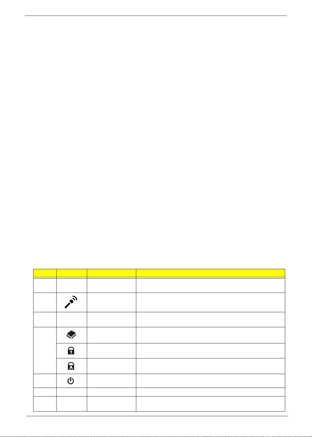
# Icon Item Description
1 Acer Crystal Eye
webcam
2 Microphone Internal microphone for recording sound.
3 Display screen Also called Liquid-Crystal Display (LCD), displays computer
4 HDD indicator Indicates when the HDD is active.
Num Lock
indicator
Caps Lock
indicator
5 Power button/ Turns the computer on and off.
6 Keyboard For entering data into your computer
7 Touchpad Touch-sensitive pointing device which functions like a
Chapter 1 5
Web camera for video communication. (only for certain
models)
output (configuration may vary by model).
Lights up when the Num Lock is activated.
Lights up when the Caps Lock is a c ti va te d.
computer mouse.
Page 16
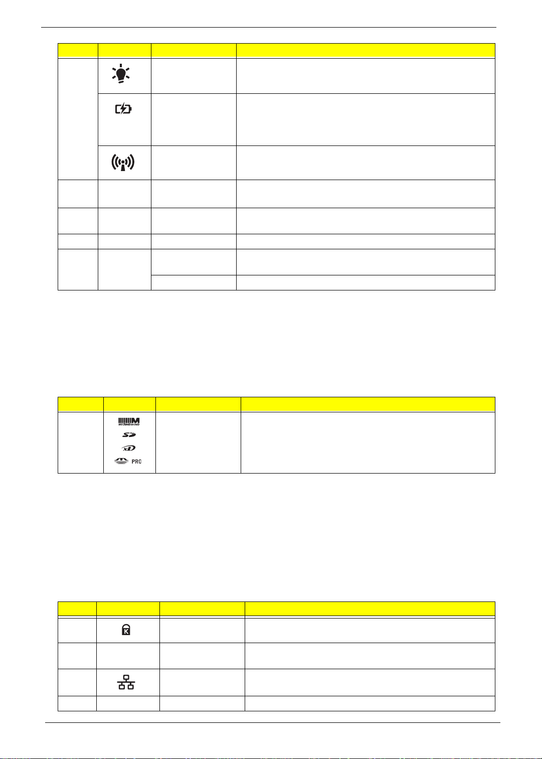
# Icon Item Description
8 Power Indicates the computer’s power status.
Battery Indicates the computer’s battery status.
1. Charging: The light shows amber when the light is
charging.
2. Fully charged: the light shows blue when in AC mode.
Communication
indicator
Indicates the computer’s wireless connectivity status.
9 Click buttons
(left, and right)
10 Palmrest Comfortable support area for your hand when using the
11 Speakers Left and right speakers deliver stereo audio output.
12
P
Programmable
key
The left and right buttons function like the left and right mouse
buttons.
computer.
User-programmable. (only for certain models)
Closed Front View
# Icon Item Description
1 Multi-in-1 card
reader
Accepts Secure Digital (SD), MultiMediaCard (MMC),
Memory Stick (MS), Memory Stick PRO (MS PRO), xDPicture Card (xD).
Note: Push to remove/install the card. Only one card can
operate at any given time.
Left View
# Icon Item Description
1
2
3
4 HDMI HDMI port Supports high definition digital video connections.
6 Chapter 1
Kensington lock
slot
Ventilation slots Enable the computer to stay cool, even after prolonged
Ethernet RJ-45)
port
Connects to a Kensington-compatible computer security
lock.
use.
Connects to an Ethernet 10/100/1000-based network.
Page 17
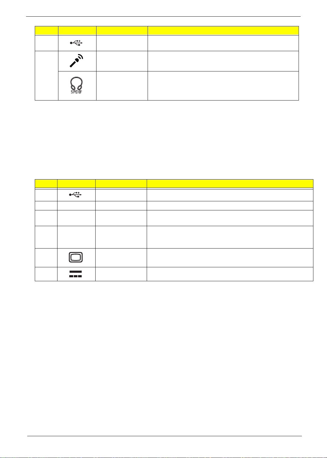
# Icon Item Description
5
6 Microphone jack Accepts inputs from external microphones.
USB 2.0 port Connects to USB 2.0 devices (e.g., USB mouse, USB
camera).
Headphones/
speaker/line-out
jack with S/PDIF
support.
Connects to audio line-out devices (e.g., speakers,
headphones).
Right View
# Icon Item Description
1
2 Optical drive Internal optical drive; accepts CDs or DVDs.
3
4
5
USB 2.0 port Connects to USB 2.0 devices (e.g., USB mouse, USB camera).
Optical disk
access indicator
Emergency eject
hole
External display
(VGA) port
Lights up when the optical drive is active.
Ejects the optical drive tray when the computer is turned off.Note:
Insert a paper clip to the emergency eject hole to eject the optical
drive tray when the computer is off.
Connects to a display device (e.g. external, LCD monitor , LCD
projector).
6
Chapter 1 7
DC-in jack Connects to an AC adapter.
Page 18
Base View
# Icon Item Description
Battery bay Houses the computer’s battery pack.
1
2
Battery lock Locks the battery in position
Note: The battery shown is for reference only. Your PC may
have a different battery depending on the model purchased.
3
4
5
6 2nd HDD bay Houses the computer’s second HDD
6
Hard disk bay Ho uses the computer’s hard disk (secured with screws)
Memory compartment Houses the computer’s main memory.
Ventilation slots and
cooling fan
Battery release latch Releases the battery for removal.
Enable the computer to stay cool, even after prolonged use.
Note: Do not cover or obstruct the opening the fan.
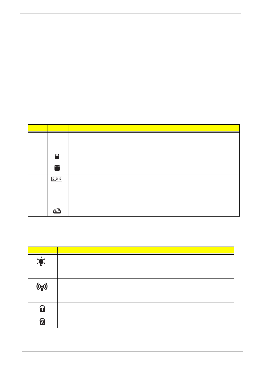
Indicators
The computer has several easy-to-read status indicators. The battery indicator is visible even when the
computer cover is closed.
Icon Function Description
Power Indicates the computer is on or off.
Battery Indicates the computer's battery status.
Wireless LAN Indicates the status of Wireless LAN communication.
HDD Indicates when the hard disk drive is active.
Num Lock Lights up when Num Lock is activated.
Caps Lock Lights up when Caps Lock is activated.
NOTE: 1. Charging: The battery light show s amber when the battery is charging. 2. Fully charged: The light
shows green when in AC mode.
8 Chapter 1
Page 19
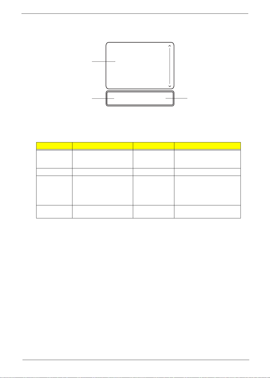
TouchPad Basics
The following items show you how to use the TouchPad:
1
2
• Move your finger across the TouchPad (1) to move the cursor.
• Press the left (2) and right (3) buttons located beneath the TouchPad to perform selectio n and
execution functions. These two buttons are the equivalent of the left and right buttons on a mouse.
Tapping on the TouchPad is the same as clicking the left button.
Function Left Button (2) Right Button (3) Main TouchPad (1)
Execute Quickly click twice. Tap twice (at the same speed
Select Click once. Tap once.
Drag Click and hold, then use
finger on the TouchPad to
drag the cursor.
Access
context menu
NOTE: When using the T ouchPad, keep it - and your fingers - dry and clean. The TouchPad is sensitive to
finger movement; hence, the lighter the touch, the better the response. Tapping too hard will not
increase the TouchPad’s responsiveness.
Click once.
3
as double-clicking a mouse
button).
Tap twice (at the same speed
as double-clicking a mouse
button); rest your finger on
the TouchPad on the second
tap and drag the cursor.
Chapter 1 9
Page 20
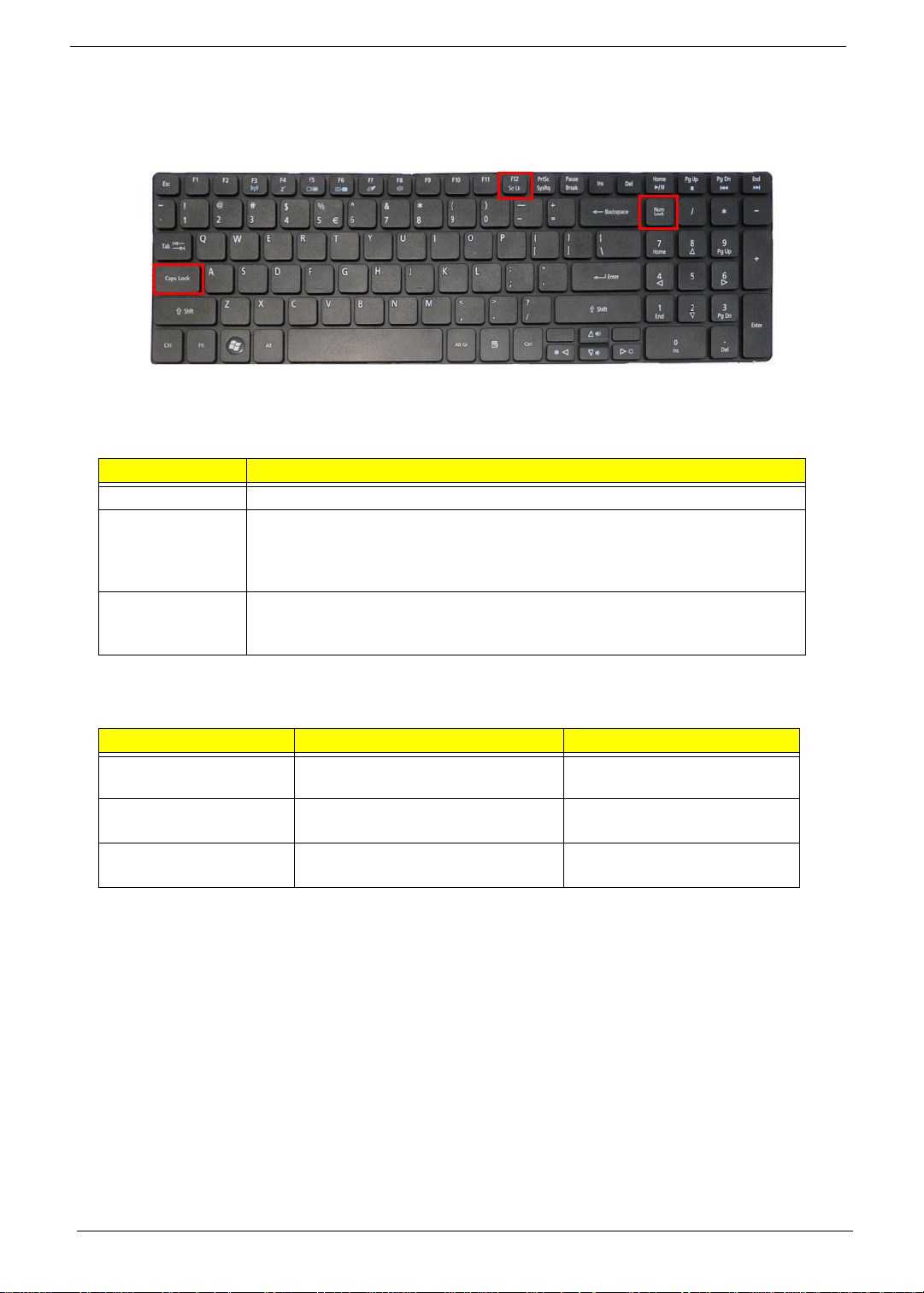
Using the Keyboard
Your computer has a close-to-full-sized keyboard and an embedded numeric keypad, separate cursor, lock,
function and special keys.
Lock Keys and embedded numeric keypad
The keyboard has three lock keys which you can toggle on and off.
Lock key Description
Caps Lock When Caps Lock is on, all alphabetic characters typed are in uppercase.
Num Lock When Num Lock is on, the embedded keypad is in numeric mode. The keys
function as a calculator (complete with the arithmetic operators +, -, *, and /). Use
this mode when you need to do a lot of numeric data entry. A better solution
would be to connect an external keypad.
Scroll Lock <Fn> +
<F12>
When Scroll Lock is on, the screen moves one line up or down when you press
the up or down arrow keys respectively. Scroll Lock does not work with some
applications.
The embedded numeric keypad functions like a desktop numeric keypad. It is indicated by small characters
located on the upper right corner of the keycaps. To simplify the keyboard leg end, cursor-control key symbols
are not printed on the keys.
Desired access Num Lock on Num Lock off
Number keys on
embedded keypad
Cursor-control keys on
embedded keypad
Main keyboard keys Hold <Fn> while typing letters on
Type numbers in a normal manner.
Hold <Shift> while using cursorcontrol keys.
embedded keypad.
Hold <Fn> while using cursorcontrol keys.
Type the letters in a normal
manner.
10 Chapter 1
Page 21
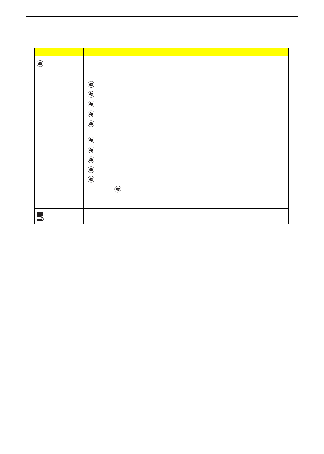
Windows Keys
The keyboard has two keys that perform Windows-specific functions.
Key Description
Windows key Pressed alone, this key has the same effect as clicking on the Windows Start button;
it launches the Start menu. It can also be used with other keys to provide a variety of
functions:
<>: Open or close the S tart menu
<> + <D>: Display the desktop
<> + <E>: Open Windows Explore
<> + <F>: Search for a file or folder
<> + <L>: Lock your computer (if you are connected to a network domain), or
switch users (if you're not connected to a network domain)
<> + <M>: Minimizes all windows
<> + <R>: Open the Run dialog box
<> + <U>: Open Ease of Access Center
<> + <BREAK>: Display the System Properties dialog box
<> + <TAB>: Cycle through programs on the taskbar
<CTRL> + <> + <F>: Search for computers (if you are on a network)
Note: Depending on your edition of Windows 7, some shortcuts may not function as
described.
Application
key
This key has the same effect as clicking the right mouse button; it opens the
application's context menu.
Chapter 1 11
Page 22
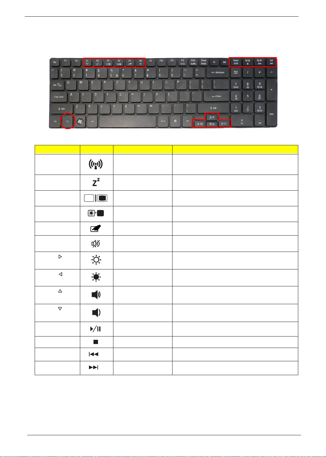
Hot Keys
The computer employs hotkeys or key combinations to access most of the computer's controls like screen
brightness and volume output.
To activate hotkeys, press and hold the <Fn> key before pressing the other key in the hotkey combination.
Hotkey Icon Function Description
<Fn> + <F3> Wireless
communication switch
<Fn> + <F4> Sleep Puts the computer in Sleep mode.
<Fn> + <F5> Display toggle Switches display output between the display
<Fn> + <F6> Screen blank Turns the display screen backlight off to save
<Fn> + <F7> Touchpad toggle Turns the touchpad on and off.
Enables/disables the Wireless function.
screen, external monitor (if connected) and both.
power. Press any key to return.
<Fn> + <F8> Speaker toggle Turns the speakers on and off.
<Fn> + < > Brightness up Increases the screen brightness.
<Fn> + < > Brightness down Decreases the screen brightness.
<Fn> + < >
<Fn> + < >
<Fn> + <Home> Play/Pause Plays or pauses media files
<Fn> + <Pg Up> Stop Stops media file
<Fn> + <Pg Dn> Previous Plays the previous media file in the play sequence
<Fn> + <End> Next Plays the next media file in the play sequence
Volume up Increases the sound volume.
Volume down Decreases the sound volume.
12 Chapter 1
Page 23

Special Keys
On models that support the Euro symbol and the US dollar sign, the symbols can be located at the uppercenter and/or bottom-right of your keyboard.
The Euro symbol
1. Open a text editor or word processor.
2. Hold <Alt Gr> and then press the <5> key at the upper-center of the keyboard.
NOTE: Some fonts and software do not support the Euro symbol. See www.microsoft.com/typography/faq/
faq12.htm for more information.
The US dollar sign
1. Open a text editor or word processor.
2. Hold <Shift> and then press the <4> key at the upper-center of the keyboard.
NOTE: This function varies according to the language settings.
Chapter 1 13
Page 24
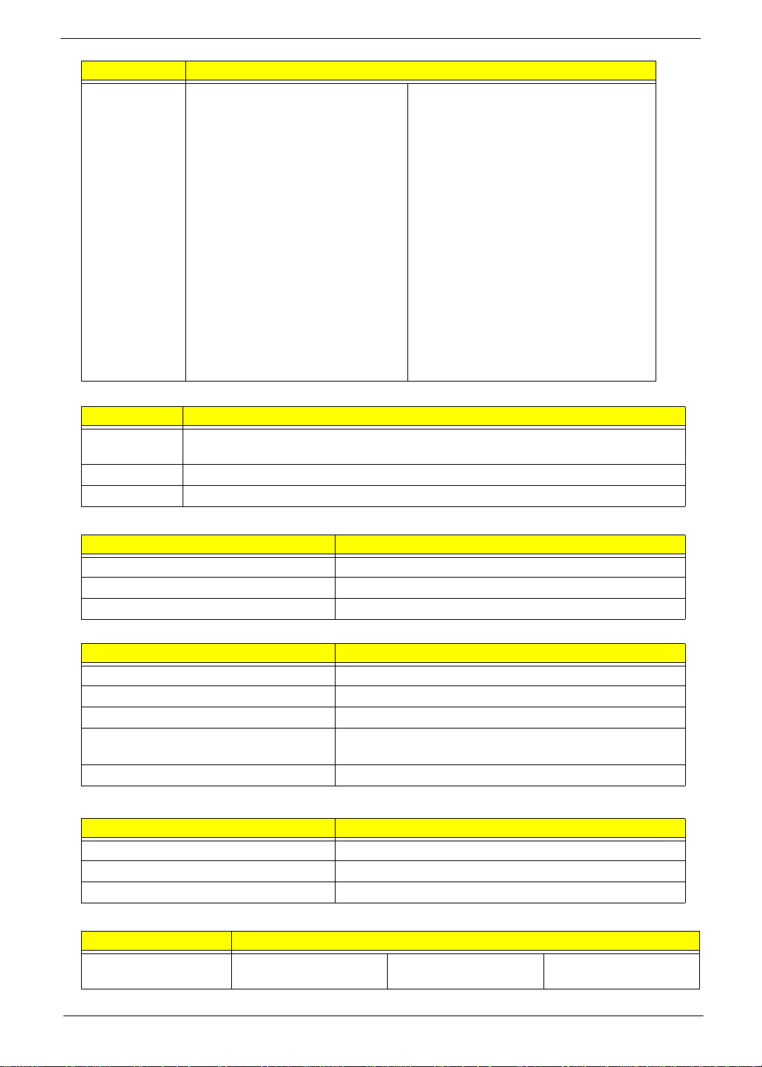
Hardware Specifications and Configurations
Processor
Item Specification
CPU •
Type •
CPU Package
Power
On-die Cache •
Front Side Bus
Processor Specifications
Item
CPU Fan True Value Table (UMA)
CPU Temperature
(Celcius)
CPU
Speed
Cores Bus Speed Cache Size Package
Fan Speed (RPM) SPL Spec (dBA)
Core
Voltage
Acer P/N
Throttling 50%: On= 100°C; OFF=85°C
OS shut down at 105°C; H/W shut down at 110°C
CPU Fan True Value Table (Discrete)
CPU Temperature
(Celcius)
Throttling 50%: On= 100°C; OFF=85°C
OS shut down at 105°C; H/W shut down at 110°C
Core Logic Specifications
Item Specification
Chipset
Package
Features •
Fan Speed (RPM) SPL Spec (dBA)
14 Chapter 1
Page 25
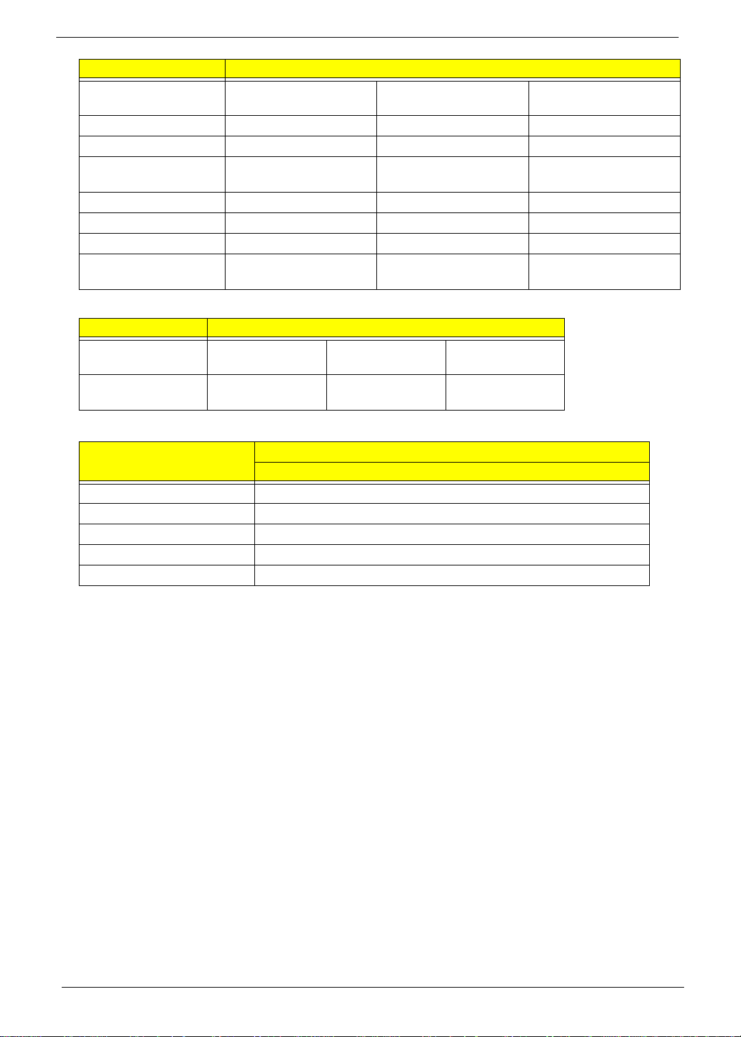
System Memory
Item Specification
Memory size 0MB (No on-board Memory)
DIMM socket number 2 sockets
Supports memory size per socket 4GB
Supports maximum memory size 8GB
Supports DIMM type DDR3 64 bit
Supports DIMM Speed 1066/1333 MHz
Video Specifications
Item Specification
Chipset
Type
Package •
Features • •
Hard Disk Drive Interface
Item Specification
Vendor & Model
Name
Capacity (GB) 160, 250, 320,
Bytes per sector 512
Data heads 2-4
Drive Format
Disks 1-2
Spindle speed
(RPM)
Performance Specifications
Buffer size 8 MB
Interface SATA
DC Power Requirements
Voltage
tolerance
Seagate HGST Toshiba Western Digital
160, 250,
500
5V ±5% 5V ±5% 5V ±5% 5V ±5%
320, 500
5400
160, 250,
320, 500
160, 250, 320,
500, 640
BIOS
Item Specification
BIOS vendor Insyde BIOS
BIOS version 3.5
BIOS ROM type Flash
Chapter 1 15
Page 26
Item Specification
Features • Flash ROM 4MB
• Support ISIPP
• Support Acer UI
• Support multi-boot
• Suspend to RAM (S3)/Disk (S4)
• V arious hot-key s for system control
• Support SMBIOS 2.3, PCI2.2.
• Refer to Acer BIOS specification.
• DMI utility for BIOS serial number configurable/asset tag
• Support PXE
• Support Y2K solution
• Support WinFlash
• Wake on LAN from S3
• Wake on LAN form S4 in AC mode
• System information
LCD 17.3”
Item Specification
Vendor/model name AUO/ ChiMei LG Samsung
Screen Diagonal (mm) 17.3 inches
Display resolution (pixels) 1600x3(RGB) x 900
Pixel Pitch 0.2388X0.2388
Display Mode Normally White
Typical White Luminance (cd/m
2
)
220 typical
(also called Brightness)
Contrast Ratio 500 typical 500 600 600
Response Time (Optical Rise
8/16 2/8 8/16 8
Time/Fall Time) msec
Luminance Uniformity 1.25 max
Electrical Interface LVDS
Support Color 262K
Viewing Angle (up/down/right/
left)
15/35/45/45
20/45/45/45
10/30/40/40 15/30/40/40
Temperature Range (°C)
Operating
Storage (shipping)
0 to +50
-20 to +60
Bluetooth
Item Specification
Bluetooth
Controller
Foxconn BCM2046 BT2.1+EDR
Module (T60H928.33)
Foxconn AR3011 BT Module
(T77H056.00)
16 Chapter 1
Page 27
Item Specification
Features • Fully Qualified Bluetooth v2.1
with Class 2 specification RF
output power.
• Enhanced Data Rate (EDR)
compliant.
• Full Piconet and Scatternet
operation.
• Integrated PIFA Antenna with
better RF performance.
• USB 2.0 compliant interface.
• F/W upgradable via Flash
downloads.
• Very low power consumption.
• Support Coexistence with Intel
WCS (Wireless Coexistence
System) & AFH (Adaptive
Frequency Hopping).
Audio Codec and Amplifier
Item Specification
Audio
Controller
Package
Features •
• Single-chip Bluetooth v2.1 + EDR
solution
• USB 2.0 full-speed device interface
with support for Device Firmware
Upgrade(DFU)
• SPI interface supports external serial
flash devices
• Two on-chip 1.2V linear voltage
regulators
• Integrated 32-bit CPU with 32KB
data RAM and 256KB program RAM
• On-board PLL
• On-chip low power oscillator(LPO)
• WLAN coexistence interface
• Standard USB HCI interface
LAN Interface
Item Specification
LAN Chipset
Package
Features •
Keyboard
Item Specification
Type
Total number of keypads
Windows logo key
Internal & external keyboard work
simultaneously
Features •
Media Card Reader
Item Specification
Chipset
Package
Features •
Camera 1.3M
Item Specifications
Vendor and model SUYIN HF1315-S32B-
OV0
Chicony CNF9157 Liteon 09P2BF127 /
Liteon 09P2SF119
Chapter 1 17
Page 28
Item Specifications
Type CMOS image sensor
with SXGA
Interface USB Port 2.0 USB Port 2.0 USB Port 2.0
Focusing distance 70cm 70 cm 60 cm
Dimensions (L x W x H
mm)
Sensor type OV9665 TBC OV9665
Pixel resolution 1280x1024 1280x1024 1280x1024
Pixel size 2 µm x 2 µm TBC 2 µm x 2 µm
Image size 3.89mm(H) X
Wireless LAN
Type Realtek
Wireles Standards
Supported
Battery
65 x 8.0 x 3.74 mm 65.0±0.3 X 8.0±0.1 X
2.43mm(V)Part number
Atheros AR5B93 Intel WiFi Link
RTL819SE
b, g,n b, g, n b, g, Draft-N
CMOS image sensor
with SXGA
3.69+0.11/-0.2 mm
TBC TBC
Specification
1000
CMOS image sensor
with SXGA
65.0 x 8.0 x 3.53 ±
0.2mm
Item
Vendor & model name
Battery Type
Pack capacity
Number of battery cell
Package configuration
Specification
6 Cell
18 Chapter 1
Page 29

Chapter 2
System Utilities
BIOS Setup Utility
The BIOS Setup Utility is a hardware configuration program built into your computer’s BIOS (Basic Input/
Output System).
Y our computer is already properly configured and optimized, and you do not need to run this utility . However, if
you encounter configuration problems, you may need to run Setup. Please also refer to Chapter 4
Troubleshooting when problem arises.
To activate the BIOS Utility, press F2 during POST (when Press <F2> to enter Setup message is prompted
on the bottom of screen).
Press F2 to enter setup. The default parameter of F12 Boot Menu is set to “disabled”. If you want to change
boot device without entering BIOS Setup Utility, please set the parameter to “enabled”.
Press <F12> during POST to enter multi-boot menu. In this menu, user can change boot device without
entering BIOS SETUP Utility.
Navigating the BIOS Utility
There are five menu options: Information, Main, Security, Boot, and Exit.
Follow these instructions:
• To choose a menu, use the left and right arrow keys.
• To choose an item, use the up and down arrow keys.
• To change the value of a parameter, press F5 or F6.
• Press Esc while you are in any of the menu options to go to the Exit menu.
• In any menu, you can load default settings by pressing F9. You can also press F10 to save any
changes made and exit the BIOS Setup Utility.
NOTE: You can change the value of a parameter if it is enclosed in square brackets. Navigation keys for a
particular menu are shown on the bottom of the screen. Help for parameters are found in the Item
Specific Help part of the screen. Read this carefully when making changes to parameter values. Please
note that system information is subject to different models.
Chapter 2 19
Page 30
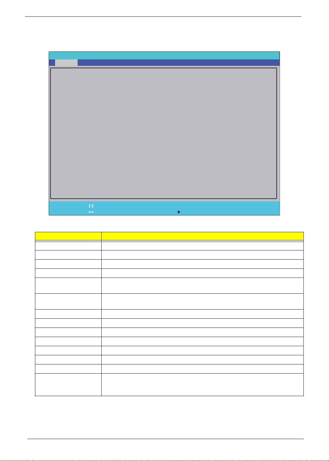
Information
The Information screen displays a summary of your computer hardware information.
Phoenix SecureCore (tm) Setup Utility
SecurityInformation
Main
Boot
Exit
CPU Type:
CPU Speed:
IDE0 Model Name:
IDE0 Serial Number:
Intel(R) Core (TM) i3 CPU M 330 @ 2.13GHz
2130 MHz
Hitachi HTS545016B9A300
091202PBGK061SHPZ7TN
IDE1 Model Name: ST9160314AS
IDE0 Serial Number: 5VCCGNQJ
ATAPI Model Name:
System BIOS Version:
VGA BIOS Version:
Optiarc DVD RW AD-7585H
V1.00
ATi 012.020.000.000.035257
Serial Number:
Asset Tag Number:
Product Name:
Manufacturer Name:
UUID:
Help
F1
Exit
ESC
NOTE: The system information is subject to different models.
Parameter Description
CPU Type This field shows the CPU type and speed of the system.
CPU Speed This field shows the speed of the CPU.
IDE0 Model Name This field shows the model name of HDD installed on primary IDE master.
IDE0 Serial Number This field displays the serial number of HDD installed on primary IDE master.
IDE1 Serial Number This field shows the model name of the device nstalled on secondary IDE
IDE1 Serial Number This field displays the serial number of the device installed on secondary IDE
ATAPI Model Name This field displays the model name of th e installed ODD drive .
System BIOS Version Displays system BIOS version.
VGA BIOS Version This field displays the VGA firmware version of the system.
Serial Number This field displays the serial number of this unit.
Asset Tag Number This field displays the asset tag number of the system.
Product Name This field shows product name of the system.
Manufacturer Name This field displays the manufacturer of this system.
UUID Number Universally Unique Identifier (UUID) is an identifier standard used in software
Select Item
Select Menu
master.
master.
construction, standardized by the Open Software Foundation (OSF) as part of
the Distributed Computing Environment (DCE).
T
Acer
3F9d87877F6947639685
F5/F6
Enter
Change Values
Select SubMenu
Setup Default
F9
Save and Exit
F10
20 Chapter 2
Page 31

Main
The Main screen allows the user to set the system time and date as well as enable and disable boot option
and recovery.
Phoenix SecureCore (tm) Setup Utility
Information
System Time:
System Time:
System Date:
System Date:
Total Memory:
Total Memory:
Video Memory:
Video Memory:
Grahpic Mode: [Switchable]
Grahpic Mode: [Switchable]
Quiet Boot
Quiet Boot
Network Boot
Network Boot
F12 Boot Menu
F12 Boot Menu
D2D Recovery
D2D Recovery
SATA Mode
SATA Mode
Main
Security
[19:10:59]
[19:10:59]
[02/05/2010]
[02/05/2010]
2048 MB
2048 MB
1024 MB
1024 MB
[Enabled]
[Enabled]
[Enabled]
[Enabled]
[Disabled]
[Disabled]
[Enabled]
[Enabled]
[AHCI Mode]
[AHCI Mode]
Boot
Exit
Item Specific Help
<Tab>, <Shift-Tab>, or
<Enter> selects field.
Help
F1
Exit
ESC
NOTE: The screen above is for your reference only. Actual values may differ.
The table below describes the parameters in this screen. Settings in boldface are the default and suggested
parameter settings.
Parameter Description Format/Option
System Time Sets the system time. The hours are displayed with 24-
hour format.
System Date Sets the system date. Format MM/DD/YYYY
Total Memory This field reports the memory size of the system. N/A
Video Memory
Graphic Mode
Quiet Boot This will hide POST messages while booting. Option: Enabled or Disabled
Network Boot Enables, disables the system boot from LAN (remote
F12 Boot Menu Enables, disables Boot Menu during POST. Option: Disabled or Enabl ed
D2D Recovery Enables, disables D2D Recovery function. The function
SATA Mode Control the mode in which the SATA controller should
Shows the video memory size. VGA Memory size=32 MB
Sets discrete VGA only for systems with XP or Linux OS.
server).
allows the user to create a hidden partition on hard disc
drive to store the operation system and restore the
system to factory defaults.
operate.
Select Item
Select Menu
F5/F6
Enter
Change Values
Select SubMenu
Setup Default
F9
Save and Exit
F10
Format: HH:MM:SS
(hour:minute:second)
(month/day/year)
N/A
Option: Switchable or
Discrete
Option: Enabled or Disabled
Option: Enabled or Disabled
Option: AHCI mode or IDE
mode
Chapter 2 21
Page 32

Security
The Security screen contains parameters that help safeguard and protect your computer from unauthorized
use.
Phoenix SecureCore (tm) Setup Utility
Information
Supervisor Password Is:
Supervisor Password Is:
User Password Is:
User Password Is:
HDD Password Is:
HDD Password Is:
Set Supervisor Password [Enter]
Set Supervisor Password [Enter]
Set User Password [Enter]
Set User Password [Enter]
Set HDD Password [Enter]
Set HDD Password [Enter]
Password on Boot:
Password on Boot:
Main Boot
Security
Clear
Clear
Clear
Clear
Clear
Clear
[Disabled]
[Disabled]
Exit
Item Specific Help
Supervisor Password
controls access to the
setup utility.
Help
F1
Exit
ESC
The table below describes the parameters in this screen. Settings in boldface are the default and suggested
parameter settings.
Parameter Description Option
Supervisor Password Is Shows the setting of the Supervisor password Clear or Set
User Password Is Shows the setting of the user password. Clear or Set
HDD Password Is Shows the setting of the HDD password Clear or Set
Set Supervisor Password Press Ente r to set the supervisor password. When
Set User Password Press Enter to set the user password. When user
Set HDD Password Press Enter to set the HDD password. When set this
Password on Boot Defines whether a password is required or not while
Select Item
Select Menu
set, this password protects the BIOS Setup Utility
from unauthorized access. The user can not either
enter the Setup menu nor change the value of
parameters.
password is set, this password protects the BIOS
Setup Utility from unauthorized access. The user can
enter Setup menu only and does not have right to
change the value of parameters.
protects the HDD from unauthorized access.
the events defined in this group happened. The suboptions all require the Supervisor password for
changes and should be grayed out if the user
password was used to enter setup.
F5/F6
Enter
Change Values
Select SubMenu
Setup Default
F9
Save and Exit
F10
Disabled or
Enabled
NOTE: When you are prompted to enter a password, you have three tries before the system halts. Don’t forget
the password. If you forget the password, you may have to reset the computer.
22 Chapter 2
Page 33

Setting a Password
Follow these steps as you set the user or the supervisor password:
1. Use the ↑ and ↓ keys to highlight the Set Supervisor Password parameter and press the Enter key. The
Set Supervisor Password box appears:
Set Supervisor Password
Enter New Password [ ][ ]
Confirm New Password [ ]
2. Type a password in the “Enter New Password” field. The password length can not exceeds 8
alphanumeric characters (A-Z, a-z, 0-9, not case sensitive). Retype the password in the “Confirm New
Password” field.
IMPORTANT:Be very careful when typing your password because the characters do not appear on the screen.
3. Press Enter. After setting the password, the computer sets the User Password parameter to “Set”.
4. If desired, you can opt to enable the Password on boot parameter.
5. When you are done, press F10 to save the changes and exit the BIOS Setup Utility.
Removing a Password
Follow these steps:
1. Use the ↑ and ↓ keys to highlight the Set Supervisor Password parameter and press the Enter key. The
Set Password box appears:
Set Supervisor Password
Enter Current Password [ ][ ]
Enter New Password [ ]
Confirm New Password [ ][ ]
2. Type the current password in the Enter Current Passwor d fi el d an d press Enter.
3. Press Enter twice without typing anything in the Enter New Password and Confirm New Password fields.
The computer then sets the Supervisor Password parameter to “Clear”.
4. When you have changed the settings, press F10 to save the changes and exit the BIOS Setup Utility.
Chapter 2 23
Page 34

Changing a Password
1. Use the ↑ and ↓ keys to highlight the Set Supervisor Password parameter and press the Enter key. The
Set Password box appears.
Set Supervisor Password
Enter Current Password [ ][ ]
Enter New Password [ ]
Confirm New Password [ ][ ]
2. Type the current password in the Enter Current Passwor d fi el d an d press Enter.
3. Type a password in the Enter New Password field. Retype the password in the Confirm New Password
field.
4. Press Enter. After setting the password, the computer sets the User Password parameter to “Set”.
5. If desired, you can enable the Password on boot parameter.
6. When you are done, press F10 to save the changes and exit the BIOS Setup Utility.
If the verification is OK, the screen will display as following.
Setup Notice
Changes have been saved.
[Continue][Continue]
The password setting is complete after the user presses Enter.
If the current password entered does not match the actual current password, the screen will show you the
Setup Warning.
Setup Warning
Invalid Password.
[Continue][Continue]
If the new password and confirm new password strings do not match, the screen displays the following
message.
Setup Warning
Passwords do not match.
Re-enter password.
[Continue][Continue]
24 Chapter 2
Page 35

Boot
This menu allows the user to decide the order of boot devices to load the operating system. Bootable devices
includes the USB diskette drives, the onboard hard disk drive and the DVD drive in the module bay.
Phoenix SecureCore (tm) Setup Utility
Information
Boot priority order:
Boot priority order:
1: IDE 0: Hitachi HTS545016B9A300-(S
1: IDE 0: Hitachi HTS545016B9A300-(S
2: IDE 5: ST9160314AS-(S6)
2: IDE 5: ST9160314AS-(S6)
3: CD/DVD: Optiarc DVD RW AD-758H-(S
3: CD/DVD: Optiarc DVD RW AD-758H-(S
4: PCI LAN: Atheros Boot Agent
4: PCI LAN: Atheros Boot Agent
5: USB HDD:
5: USB HDD:
6: USB CDROM:
6: USB CDROM:
7: USB FFD:
7: USB FFD:
8: USB KEY:
8: USB KEY:
Excluded from boot order:
Excluded from boot order:
Main
Security
Boot
Exit
Item Specific Help
Use < > or < > to select
a device, then press
<F6> to move it up the
list, or <F5> to move
it down the list.
Press <Esc> to escape
the menu.
F1
ESC
Help
Exit
Select Item
Select Menu
F5/F6
Enter
Change Values
Select SubMenu
Setup Default
F9
Save and Exit
F10
Chapter 2 25
Page 36

Exit
The Exit screen allows you to save or discard any changes you made and quit the BIOS Utility.
Phoenix SecureCore (tm) Setup Utility
Information
Exit Saving Changes
Exit Saving Changes
Exit Discarding Changes
Exit Discarding Changes
Load Setup Defaults
Load Setup Defaults
Discard Changes
Discard Changes
Save Changes
Save Changes
Main
Security
Boot
Exit
Item Specific Help
Exit System Setup and
save your changes to
CMOS.
Help
F1
Exit
ESC
The table below describes the parameters in this screen.
Parameter Description
Exit Saving Changes Exit System Setup and save your changes to CMOS.
Exit Discarding
Changes
Load Setup Default Load default values for all SETUP item.
Discard Changes Load previous values from CMOS for all SETUP items.
Save Changes Save Setup Data to CMOS.
Select Item
Select Menu
Exit utility without saving setup data to CMOS.
F5/F6
Enter
Change Values
Select SubMenu
F9
F10
Setup Default
Save and Exit
26 Chapter 2
Page 37

BIOS Flash Utility
The BIOS flash memory update is required for the following conditions:
• New versions of system programs
• New features or options
• Restore a BIOS when it becomes corrupted.
DOS Flash Utility
Perform the following steps to use the DOS Flash Utility:
1. Press F2 during boot to enter the Setup Menu.
2. Select Boot Menu to modify the boot priority order, for example, if using USB HDD to Update BIOS, move
USB HDD to position 1.
Phoenix SecureCore (tm) Setup Utility
Information
Boot priority order:
Boot priority order:
1: IDE 0: Hitachi HTS545016B9A300-(S
1: IDE 0: Hitachi HTS545016B9A300-(S
2: IDE 5: ST9160314AS-(S6)
2: IDE 5: ST9160314AS-(S6)
3: CD/DVD: Optiarc DVD RW AD-758H-(S
3: CD/DVD: Optiarc DVD RW AD-758H-(S
4: PCI LAN: Atheros Boot Agent
4: PCI LAN: Atheros Boot Agent
5: USB HDD:
5: USB HDD:
6: USB CDROM:
6: USB CDROM:
7: USB FFD:
7: USB FFD:
8: USB KEY:
8: USB KEY:
Excluded from boot order:
Excluded from boot order:
Main
Security
Boot
Exit
Item Specific Help
Use < > or < > to select
a device, then press
<F6> to move it up the
list, or <F5> to move
it down the list.
Press <Esc> to escape
the menu.
Help
F1
Exit
ESC
3. Execute the FLASH.BAT batch file to update BIOS. Or enter C:\ Flash it bios ver.fd/dc
The flash process begins as shown.
4. In flash BIOS, the message Please do not remove AC Power Source displays.
NOTE: If the AC power is not connected, the following message displays.
Chapter 2 27
Select Item
Select Menu
F5/F6
Enter
Change Values
Select SubMenu
Setup Default
F9
Save and Exit
F10
Page 38

Plug in the AC power to continue.
5. Flash is complete when the message Flash programming complete displays.
WinFlash Utility
Perform the following steps to use the WinFlash Utility:
1. Double click the WinFlash executable.
2. Click OK to begin the update. A progress screen displays.
3. When the process is complete, close all programs and applications and reboot the system.
28 Chapter 2
Page 39

Remove HDD/BIOS Password Utilities
This section provide you with removing HDD/BIOS method:
Remove HDD Password:
When the user keys in the wrong password three times, the system reports the following error code to user.
To unlock the HDD password, perform the following steps:
1. Press Enter to display the Select Item screen.
2. Select Enter Unlock Password and press Enter.
An Unlock Password displays.
3. Make a note of the key, 76943488 in the example.
4. Boot up the system to a removable bootable drive containing DOS and the UnlockHD.EXE program and
open a DOS prompt. For instructions on changing boot priority see “Boot” on page 25.
5. From the DOS prompt, enter the UnlockHD.EXE command and input the key to create an unlock code.
Make a note of the result, for example 46548274.
6. Reboot to the hard disk and wait for the error code to reappear.
7. Press Enter to display the Select Item screen.
8. Select Enter Unlock Password and press Enter.
9. Enter the unlock code generated by UnlockHD.EXE.
10. Save and exit the BIOS to complete the process.
Chapter 2 29
Page 40

Removing BIOS Passwords:
If you key in the wrong Supervisor Password three times, System Disabled displays on the screen. See the
image below.
To reset the BIOS password, run clnpwd.exe as follows:
1. From a DOS prompt, Execute clnpwd.exe
2. Press 1 or 2 to clean the desired password shown on the screen.
The onscreen message determines whether the function is successful or not.
30 Chapter 2
Page 41

Miscellaneous Utilities
Using Boot Sequence Selector
Boot Sequence Selector allows the boot order to be changes without accessing the BIOS. To use Boot
Sequence Selector, perform the following steps:
1. Enter into DOS.
2. Execute BS.exe to display the usage screen.
3. Select the desired boot sequence by entering the corresponding sequence, for example, enter BS2 to
change the boot sequence to HDD|CD ROM|LAN|Floppy.
Using DMITools
The DMI (Desktop Management Interface) Tool copies BIOS information to eeprom to be used in the DMI pool
for hardware management.
When the BIOS displays Verifying DMI pool data it is checking the table correlates with the hardware before
sending to the operating system (Windows, etc.).
To update the DMI Pool, perform the following steps:
1. Enter into DOS.
2. Execute qdmitools.exe. The following messages show dmitools usage:
Chapter 2 31
Page 42

3. Enter the required key number of the feature required to be modified. See the following table.
Key No. Function Description
1 Enter 1 to modify the Asset Tag
2 Enter 2 to modify the Product Name
3 Enter 3 to modify the Serial Number
4 Enter 4 to modify the 1394 GUID Number
0 Enter 0 to exit the program
Using the LAN MAC Utility
Perform the following steps to write MAC information to eeprom:
1. Use a text editor, for example Notepad, to edit the MAC.CFG file as shown:
• WriteData= '00112233445 5' <------- MAC value
• StartAddr=7A <------- MAC address
• WriteLeng=6 <------- MAC value length
• KeepByte=0 <------- can be any value
2. Boot into DOS.
3. Execute MAC.BAT to write MAC information to eeprom.
32 Chapter 2
Page 43

Chapter 3
Machine Disassembly and Replacement
This chapter contains step-by-step procedures on how to disassemble the notebook computer for
maintenance and troubleshooting.
Disassembly Requirements
To disassemble the computer, you need the following tools:
• Wrist grounding strap and conductive mat for preventing electrostatic discharge
• Flat screwdriver
• Philips screwdriver
• Plastic flat screwdriver
• Plastic tweezers
NOTE: The screws for the different components vary in size. During the disassembly process, group the
screws with the corresponding components to avoid mismatch when putting back the components.
Related Information
The product previews seen in the disassembly procedures may not represent the final product color or
configuration.
IMPORTANT: Cable paths and positioning may not represent the actual model. During the removal and
replacement of components, ensure all available cable channels and clips are used and that the cables are
replaced in the same position.
Replacement Requirements
NOTE: Cabling and components require adhesive to be applied during the replacement and reassembly
process.
NOTE: During manufacture a cyanoacrylate glue is used provided by Holdtite Adhesives LTD. This is not a
specified requirement. The reassembler is free to select an alternative appropriate adhesive.
Chapter 3 33
Page 44

Pre-disassembly Instructions
Before proceeding with the disassembly procedure, make sure that you do the following:
1. Turn off the power to the system and all peripherals.
2. Unplug the AC adapter and all power and signal cables from the system.
3. Place the system on a flat, stable surface.
34 Chapter 3
Page 45

Disassembly Process
The disassembly process is divided into the following sections:
• External components disassembly
• Main unit disassembly
• LCD module disassembly
The flowcharts provided in the succeeding disassembly sections illustrate the entire disassembly sequence.
Observe the order of the sequence to avoid damage to any of the hardware components. For example, if you
want to remove the Mainboard, you must first remove the Keyboard, and LCD Module then disassemble the
inside assembly frame in that order.
Main Screw List
Screw Quantity Acer Part Number
M2.0*3L(BK) 14
M2.5*5L(NI) 8
M2.5*4L(BNI) 12
M3.0*3.5L(NI) 6
M2.5*5L(BNI) 7
M2.0*5L 4
M2.5*6L(BNI) 38
M2.5*2L(NI) 4
Chapter 3 35
Page 46

External Module Disassembly Process
NOTE: The product previews seen in the disassembly procedures may not represent the final product color or
configuration.
Screw List
Step Screw Quantity Part No.
Base Cover Disassembly M2.5*5L(BNI) 6
2nd HDD Cover Disassembly M2.5*5L(BNI) 1
WLAN Module Disassembly M2.0*3L(BK) 1
HDD Disassembly M3.0*3.5L(NI) 2
2nd HDD Disassembly M3.0*3.5L(NI) 4
ODD Module Disassembly M2.0*3L(BK) 1
External Modules Disassembly Flowchart
Turn off system and
peripherals power
Disconnect power and
signal cables from
Remove Dummy Card
Remove Lower Cover
Remove HDD Remove WLAN BoardRemove DIMM
system
Remove Battery
Remove 2ndHDD
Cover
Remove 2ndHDD
36 Chapter 3
Page 47

Removing the Battery Pack
1. Turn the computer over.
2. Slide the battery lock/unlock latch to the unlock position.
3. Slide and hold the battery release latch to the release position (1), then slide out the battery pack from the
main unit (2).
2
1
NOTE: The battery has been highlighted with a yellow oval as shown in the above image. Please detach the
battery and follow local regulations for disposal.
Chapter 3 37
Page 48

Removing the Dummy Card
1. Press the dummy card in to allow it to spring out.
2. Pull the dummy card out.
38 Chapter 3
Page 49

Removing the Base Door
1. See “Removing the Battery Pack” on page 37.
2. Remove the six (6) screws.
Step Screw Quantity Screw Type
Base Door
Disassembly
M2.5*5L(BNI) 6
3. Lift the base door up at the finger indentation location provided in the bottom cover.
Chapter 3 39
Page 50

Removing the Hard Disk Drive Module
1. See “Removing the Battery Pack” on page 37.
2. See “Removing the Base Door” on page 39.
3. Grasp the pull tab on the top of the HDD.
4. Pull the tab horizontally to slide the HDD out of the connector dock.
5. Lift the HDD out of the lower cover.
40 Chapter 3
Page 51

6. Remove the two (2) screws of the HDD bracket.
Step Screw Quantity Screw Type
HDD Bracket
Disassembly
7. Lift the bracket away from the HDD.
M3.0*3.5L(NI) 2
Chapter 3 41
Page 52

Removing the DIMM Module
1. See “Removing the Battery Pack” on page 37.
2. See “Removing the Base Door” on page 39.
3. Push the memory module clips outwards.
4. Pull the memory module out.
42 Chapter 3
Page 53

Removing the WLAN Module
1. See “Removing the Battery Pack” on page 37.
2. See “Removing the Base Door” on page 39.
3. Detach the two (2) cables from the Wireless LAN module.
IMPORTANT:Take note of the position of the Main (black) and Auxiliary (white) connectors.
4. Remove the one (1) screw. Ensure the cables are well clear of the module.
Step Screw Quantity Screw Type
WLAN Module
Disassembly
Chapter 3 43
M2.0*3L(BK) 1
Page 54

5. Pull the WLAN module out and away.
44 Chapter 3
Page 55

Removing the 2nd HDD Module
1. See “Removing the Battery Pack” on page 37.
2. Remove the one (1) screw from the 2nd HDD module door.
Step Screw Quantity Screw Type
2nd HDD Module
Disassembly
M2.5*5L(BNI) 1
3. Remove the HDD module door from the lower cover.
Chapter 3 45
Page 56

4. Grasp the pull tab on the top of the HDD.
5. Lift the HDD out of the lower cover.
6. Remove the four (4) screws from the HDD bracket.
Step Screw Quantity Screw Type
HDD Bracket
Disassembly
M3.0*3.5L(NI) 4
46 Chapter 3
Page 57

7. Lift the bracket away from the HDD.
Chapter 3 47
Page 58

Removing the ODD Module
1. See “Removing the Battery Pack” on page 37.
2. See “Removing the Base Door” on page 39.
3. Pry the ODD from the chassis and pull the ODD completely out of the bay.
4. Remove the two (2) screws from the ODD bracket.
Step Screw Quantity Screw Type
ODD Module
Disassembly
48 Chapter 3
M2.0*3L(BK) 2
Page 59

5. Remove the ODD bracket.
6. Pry the ODD bezel off of the ODD module.
Chapter 3 49
Page 60

Main Unit Disassembly Process
IMPORTANT: Cable paths and positioning may not represent the actual model. During the removal and
replacement of components, ensure all available cable channels and clips are used and that the cables are
replaced in the same position.
NOTE: The product previews seen in the disassembly procedures may not represent the final product color or
configuration.
Main Unit Disassembly Flowchart
Remove external
modules before
proceeding
Remove keyboard
Remove upper cover
Remove CRT Cable
Remove LCD module
Remove DC cable
Screw List
Step Screw Quantity Part No.
Upper Cover
Disassembly
Lower Cover
Disassembly
Remove USB Board
Remove LAN Board
TBD
TBD
Remove Bluetooth
Module
Remove main board
Remove RTC Battery
Remove thermal
module
Remove CPU
Remove Power BoardRemove Switch Board
Remove PCH
Heatsink
Switch Board
M2.5*2L(NI) 2
Disassembly
Power Module
M2.0*3L(BK) 3
Disassembly
USB board
M2.5*6L(BNI) 1
Disassembly
50 Chapter 3
Page 61

Step Screw Quantity Part No.
Bluetooth Module
Disassembly
LAN Board
Disassembly
PCH Heatsink
Disassembly
LCD Module
Disassembly
TBD
TBD
TBD
M2.5*6L(BNI) 4
Chapter 3 51
Page 62

Removing the Keyboard
IMPORTANT: The keyboard is easily warpe d or damage d during the removal process. Take care not to use
excessive force when removing to prevent damage.
1. See “Removing the Battery Pack” on page 37.
2. See “Removing the Base Door” on page 39.
3. See “Removing the DIMM Module” on page 42.
4. See “Removing the WLAN Module” on page 43.
5. See “Removing the 2nd HDD Module” on page 45.
6. See “Removing the ODD Module” on page 48.
7. Remove the twenty two (22) screws in the lower cover.
Step Screw Quantity Screw Type
Lower Cover
Disassembly
8. Using plastic tweezers, release the six (6) clips holding the keyboard in place.
M2.5*6.0 (red callouts) 2 2
M2.5*2L(NI) (green
callouts)
2
52 Chapter 3
Page 63

9. Gently pry up the keyboard.
10. Carefully flip the keyboard over.
11. Detach the keyboard FCC and remove the keyboard.
Chapter 3 53
Page 64

Removing the Upper Cover
1. See “Removing the Keyboard” on page 52.
2. Disconnect the power board FFC.
3. Unlock and disconnect the touchpad board FFC.
4. Unlock and disconnect the speaker cable.
54 Chapter 3
Page 65

5. Remove the seven (7) screws from the upper cover.
Step Screw Quantity Screw Type
Upper Cover
Disassembly
2.5*4.0 (red callouts) 6
2.0*3.0 (green callout) 1
Chapter 3 55
Page 66

6. Lift the upper cover away from the lower cover as shown.
Removing the LCD Module
1. See "Removing the Upper Cover" on page 54
2. Pull the WLAN antenna up through the upper cover and free it from the cable channel.
3. Using the pull tab, release the LVDS cable from the connector.
56 Chapter 3
Page 67

4. Remove the four (4) screws from the hinges.
Step Screw Quantity Screw Type
Remove LCD
Module
5. Remove the LCD module from the chassis.
CAUTION: Make sure all cables are pulled back and away from the device to avoid damage during removal.
M2.5*6.0 4
Chapter 3 57
Page 68

Removing the Bluetooth Module
1. See “Removing the Upper Cover” on page 54.
2. Disconnect the Bluetooth cable from the mainboard..
3. Remove the one (1) screw from the Bluetooth module.
Step Screw Quantity Screw Type.
Bluetooth Module
Disassembly
4. LIft the Bluetooth module away from the upper cover.
M2.5*3 1
58 Chapter 3
Page 69

5. Detach the Bluetooth module cable from the module.
Chapter 3 59
Page 70

Removing the USB Board
1. See “Removing the Upper Cover” on page 54.
2. Unlock the USB board connector and disconnect the cable from the mainboard.
3. Peel the cable off the adhesive.
IMPORTANT:Take care not to tear the FFC pull tab during removal.
4. Unlock the USB board cable connector and disconnect the cable from the board.
60 Chapter 3
Page 71

5. Remove one (1) screw from the USB board.
Step Screw Quantity Screw Type.
USB Module
Disassembly
6. Lift the USB board clear of the chassis.
2.5*6 1
Chapter 3 61
Page 72

Removing the Mainboard
1. See “Removing the Upper Cover” on page 54.
2. Disconnect the following cables (a,b) from the mainboard.
b
a
a
b
62 Chapter 3
Page 73

3. Remove three (3) screws from the mainboard.
Step Screw Quantity Screw Type.
Main Board
Disassembly
4. Lift the mainboard out of the chassis as shown.
M2.5*6 2
Chapter 3 63
Page 74

Removing the LAN Board
1. See “Removing the Mainboard” on page 62.
2. Remove two (2) screws from the LAN board.
Step Screw Quantity Screw Type.
LAN Module
Disassembly
M2.5*6.0 2
3. Lift the LAN board clear of the chassis.
64 Chapter 3
Page 75

Removing the RTC Battery
1. See “Removing the Mainboard” on page 62.
2. Pull the RTC battery off the mainboard.
NOTE: The RTC battery has been highlighted with the yellow circle as shown in the previous image. Please
detach the RTC battery and follow local regulations for disposal.
Chapter 3 65
Page 76

Removing the Thermal Module
1. See “Removing the Mainboard” on page 62.
2. Disconnect the thermal module fan connector.
3. Loosen the six (6) captive screws from the thermal module.
66 Chapter 3
Page 77

4. Lift the thermal module away from the main board.
Chapter 3 67
Page 78

Removing the CPU
1. See “Removing the Thermal Module” on page 66.
2. Unlock the CPU. Use a flathead screw driver to turn the screw 180º.
3. Lift the CPU out of the socket.
68 Chapter 3
Page 79

Removing the PCH Heatsink
1. See “Removing the Mainboard” on page 62.
2. Loosen the two (2) captive screws.
3. Lift the thermal unit away.
Step Screw Quantity Screw Type.
Removing the PCH
Heatsink
M2.5*6.0 2
NOTE: Circuit boards >10 cm² have been highlighted with a yellow rectangle as shown in the
previous image. Please detach the circuit board and follow local regulations for disposal.
Chapter 3 69
Page 80

Removing the DC-IN Cable Assembly
1. See “Removing the Mainboard” on page 62.
2. See “Removing the Upper Cover” on page 54.
3. Remove the DC-IN cable from the retention guides.
4. Lift the DC-IN cable assembly out of the chassis.
70 Chapter 3
Page 81

Removing the Switch Board
1. See “Removing the Upper Cover” on page 54.
2. Remove the two (2) screws.
Step Screw Quantity Screw Type
Switch Board
Disassembly
M2.5*2Ni 2
3. Lift the switch board away from the upper cover (1) and turn it over (2).
1
2
Chapter 3 71
Page 82

4. Unlock and disconnect the switch board FFC.
72 Chapter 3
Page 83

Removing the Power Board
1. See “Removing the Upper Cover” on page 54.
2. Unlock and disconnect the power board FFC.
Chapter 3 73
Page 84

3. Remove the three (3) screws.
Step Screw Quantity Screw Type
Power Board
Disassembly
4. Lift the power board away.
2.0*3 3
74 Chapter 3
Page 85

LCD Module Disassembly Process
IMPORTANT: Cable paths and positioning may not represent the actual model. During the removal and
replacement of components, ensure all available cable channels and clips are used and that the cables are
replaced in the same position.
NOTE: The product previews seen in the disassembly procedures may not represent the final product color or
configuration.
LCD Module Disassembly Flowchart
Remove LCD panel
from main unit before
proceeding
Remove LCD bezel
Remove camera
module
Remove LCD panel
Remove microphone
Remove WLAN
antennas
Screw List
Step Screw Quantity Part No.
LCD Bezel
Disassembly
LCD Panel
Disassembly
Left Hinge
Disassembly
Right Hinge
Disassembly
Remove LCD bracketsRemove LVDS cable
Chapter 3 75
Page 86

Removing the LCD Bezel
1. See “Removing the Upper Cover” on page 54.
2. Remove the two (2) screws from the LCD bezel as shown.
Step Screw Quantity Screw Type.
Removing the LCD
Bezel
2.5*4 2
3. Pry the bezel away from the top-center and then work around until the entire bezel is detached.
76 Chapter 3
Page 87

4. Remove the bezel from the LCD module.
Chapter 3 77
Page 88

Removing the Camera Board
1. See “Removing the LCD Bezel” on page 76.
2. Pull up the camera board.
3. Disconnect the camera connector.
78 Chapter 3
Page 89

Removing the LCD Panel
1. See “Removing the LCD Bezel” on page 76.
2. Remove the six (6) screws from the LCD panel.
Step Screw Quantity Screw Type
LCD Panel
Disassembly
2.5*4 6
3. Remove LVDS cable from cable guides
Chapter 3 79
Page 90

4. Disconnect the microphone cable.
5. Lift the LCD panel out.
6. Remove 6 screws from the LCD brackets (3 on each side).
Step Screw Quantity Screw Type
LCD Bracket
Disassembly
80 Chapter 3
2.5*4 6
Page 91

7. Separate the brackets from the panel as shown.
8. Peel the LVDS cable off the panel.
9. Continue peeling the cable off the LCD panel.
Chapter 3 81
Page 92

10. Peel back the mylar tape and disconnect the LVDS cable.
11. Remove the adhesive foil tabs covering the microphone cable.
12. Lift up the microphone cable and remove it from the LCD cover.
82 Chapter 3
Page 93

Removing the Antennas
1. See “Removing the LCD Panel” on page 79.
2. Remove the antenna cables from the retention guides.
3. Free the cables completely.
4. Pry the left antenna from the casing.
Chapter 3 83
Page 94

5. Pry the right antenna from the casing.
84 Chapter 3
Page 95

LCD Reassembly Procedure
Replacing the Microphone
1. Lay the microphone cable in the LCD cover and replace the adhesive foil tabs.
2. Replace the microphone.
Chapter 3 85
Page 96

Replacing the Antennas
1. See See “Replacing the Microphone” on page 85.
2. Adhere the left antenna down firmly onto the LCD module casing.
3. Adhere the right antenna down firm ly on to the LCD module casing.
86 Chapter 3
Page 97

4. Lay the cables around the module edge.
Chapter 3 87
Page 98

Replacing the LCD Panel
1. See “Replacing the Antennas” on page 86.
2. Connect the FPC cable connector.
3. Place the protective clear adhesive mylar tape down firmly over the connector.
4. Continue adhering the webcam cable to the LCD panel.
88 Chapter 3
Page 99

5. Adhere the webcam cable to the back of the LCD panel, in parallel with the panel edges.
6. Replace the brackets to the panel as shown.
7. Replace the six (6) screws to the LCD brackets (3 on each side).
Chapter 3 89
Page 100

8. Replace the LCD panel into the top cover.
9. Replace the six (6) screws to the LCD panel.
10. Connect the microphone cable.
90 Chapter 3
 Loading...