


Aspire 5740/5740D/5340 Series
Service Guide
Service guide files and updates are available
on the ACER/CSD web; for more information,
please refer to http://csd.acer.com.tw
PRINTED IN TAIWAN

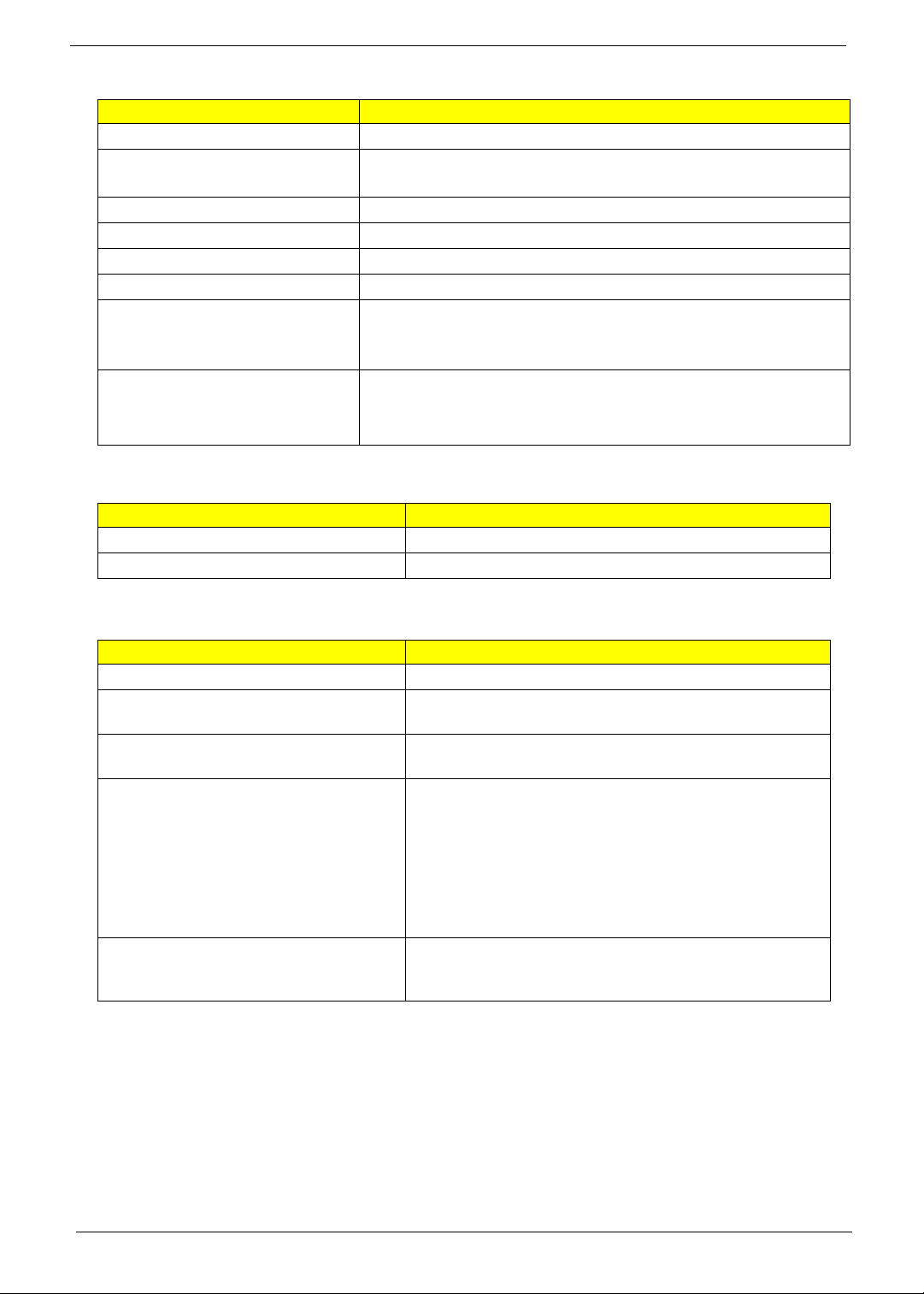
Revision History
Please refer to the table below for the updates made on Aspire 5740/5740D/5340 Series service guide.
Date Chapter Updates
II

Copyright
Copyright © 2009 by Acer Incorporated. All rights reserved. No part of this publication may be reproduced,
transmitted, transcribed, stored in a retrieval system, or translated into any language or computer language, in
any form or by any means, electronic, mechanical, magnetic, optical, chemical, manual or otherwise, without
the prior written permission of Acer Incorporated.
Disclaimer
The information in this guide is subject to change without notice.
Acer Incorporated makes no representations or warranties, either expressed or implied, with respect to the
contents hereof and specifically disclaims any warranties of merchantability or fitness for any particular
purpose. Any Acer Incorporated software described in this manual is sold or licensed "as is". Should the
programs prove defective following their purchase, the buyer (and not Acer Incorporated, its distributor, or its
dealer) assumes the entire cost of all necessary servicing, repair, and any incidental or consequential
damages resulting from any defect in the software.
Acer is a registered trademark of Acer Corporation.
Intel is a registered trademark of Intel Corporation.
Pentium and Pentium II/III are trademarks of Intel Corporation.
Other brand and product names are trademarks and/or registered trademarks of their respective holders.
III

Conventions
The following conventions are used in this manual:
SCREEN MESSAGES Denotes actual messages that appear
on screen.
NOTE Gives bits and pieces of additional
information related to the current
topic.
WARNING Alerts you to any damage that might
result from doing or not doing specific
actions.
CAUTION Gives precautionary measures to
avoid possible hardware or software
problems.
IMPORTANT Reminds you to do specific actions
relevant to the accomplishment of
procedures.
IV

Preface
Before using this information and the product it supports, please read the following general information.
1. This Service Guide provides you with all technical information relating to the BASIC CONFIGURATION
decided for Acer's "global" product offering. To better fit local market requirements and enhance product
competitiveness, your regional office MAY have decided to extend the functionality of a machine (e.g.
add-on card, modem, or extra memory capability). These LOCALIZED FEATURES will NOT be covered
in this generic service guide. In such cases, please contact your regional offices or the responsible
personnel/channel to provide you with further technical details.
2. Please note WHEN ORDERING FRU PARTS, that you should check the most up-to-date information
available on your regional web or channel. If, for whatever reason, a part number change is made, it will
not be noted in the printed Service Guide. For ACER-AUTHORIZED SERVICE PROVIDERS, your Acer
office may have a DIFFERENT part number code to those given in the FRU list of this printed Service
Guide. You MUST use the list provided by your regional Acer office to order FRU parts for repair and
service of customer machines.
V

VI

Table of Contents
System Specifications 1
Features . . . . . . . . . . . . . . . . . . . . . . . . . . . . . . . . . . . . . . . . . . . . . . . . . . . . . . . . . . . .1
Dimension and weight . . . . . . . . . . . . . . . . . . . . . . . . . . . . . . . . . . . . . . . . . . . . . .3
System Block Diagram . . . . . . . . . . . . . . . . . . . . . . . . . . . . . . . . . . . . . . . . . . . . . . . .4
Your Acer Notebook tour . . . . . . . . . . . . . . . . . . . . . . . . . . . . . . . . . . . . . . . . . . . . . . .5
Closed front view . . . . . . . . . . . . . . . . . . . . . . . . . . . . . . . . . . . . . . . . . . . . . . . . .6
Rear view . . . . . . . . . . . . . . . . . . . . . . . . . . . . . . . . . . . . . . . . . . . . . . . . . . . . . . .7
Left view . . . . . . . . . . . . . . . . . . . . . . . . . . . . . . . . . . . . . . . . . . . . . . . . . . . . . . . .7
Right view . . . . . . . . . . . . . . . . . . . . . . . . . . . . . . . . . . . . . . . . . . . . . . . . . . . . . . .8
Base view. . . . . . . . . . . . . . . . . . . . . . . . . . . . . . . . . . . . . . . . . . . . . . . . . . . . . . . 9
Indicators . . . . . . . . . . . . . . . . . . . . . . . . . . . . . . . . . . . . . . . . . . . . . . . . . . . . . .10
Easy-Launch Buttons . . . . . . . . . . . . . . . . . . . . . . . . . . . . . . . . . . . . . . . . . . . . .10
Touchpad basics (with two-click buttons) . . . . . . . . . . . . . . . . . . . . . . . . . . . . . .10
Using the Keyboard . . . . . . . . . . . . . . . . . . . . . . . . . . . . . . . . . . . . . . . . . . . . . . . . . .11
Lock Keys and embedded numeric keypad . . . . . . . . . . . . . . . . . . . . . . . . . . . .11
Windows Keys . . . . . . . . . . . . . . . . . . . . . . . . . . . . . . . . . . . . . . . . . . . . . . . . . .12
Hot Keys . . . . . . . . . . . . . . . . . . . . . . . . . . . . . . . . . . . . . . . . . . . . . . . . . . . . . . .13
Special Key (only for certain models) . . . . . . . . . . . . . . . . . . . . . . . . . . . . . . . . .13
Hardware Specifications and Configurations . . . . . . . . . . . . . . . . . . . . . . . . . . . . . . .14
System Utilities 21
BIOS Setup Utility . . . . . . . . . . . . . . . . . . . . . . . . . . . . . . . . . . . . . . . . . . . . . . . . . . . .21
Navigating the BIOS Utility . . . . . . . . . . . . . . . . . . . . . . . . . . . . . . . . . . . . . . . . .22
Information . . . . . . . . . . . . . . . . . . . . . . . . . . . . . . . . . . . . . . . . . . . . . . . . . . . . .23
Main . . . . . . . . . . . . . . . . . . . . . . . . . . . . . . . . . . . . . . . . . . . . . . . . . . . . . . . . . .24
Security . . . . . . . . . . . . . . . . . . . . . . . . . . . . . . . . . . . . . . . . . . . . . . . . . . . . . . . .26
Boot . . . . . . . . . . . . . . . . . . . . . . . . . . . . . . . . . . . . . . . . . . . . . . . . . . . . . . . . . . .29
Exit . . . . . . . . . . . . . . . . . . . . . . . . . . . . . . . . . . . . . . . . . . . . . . . . . . . . . . . . . . .30
BIOS Flash Utility . . . . . . . . . . . . . . . . . . . . . . . . . . . . . . . . . . . . . . . . . . . . . . . . . . . .31
Remove HDD Password . . . . . . . . . . . . . . . . . . . . . . . . . . . . . . . . . . . . . . . . . . . . . . .32
Disassembly Requirements . . . . . . . . . . . . . . . . . . . . . . . . . . . . . . . . . . . . . . . . . . . .33
Machine Disassembly and Replacement 33
General Information . . . . . . . . . . . . . . . . . . . . . . . . . . . . . . . . . . . . . . . . . . . . . . . . . .34
Pre-disassembly Instructions . . . . . . . . . . . . . . . . . . . . . . . . . . . . . . . . . . . . . . . .34
Disassembly Process . . . . . . . . . . . . . . . . . . . . . . . . . . . . . . . . . . . . . . . . . . . . .34
External Module Disassembly Process . . . . . . . . . . . . . . . . . . . . . . . . . . . . . . . . . . .35
External Modules Disassembly Flowchart . . . . . . . . . . . . . . . . . . . . . . . . . . . . .35
Removing the Battery Pack . . . . . . . . . . . . . . . . . . . . . . . . . . . . . . . . . . . . . . . . .36
Removing the SD Dummy Card . . . . . . . . . . . . . . . . . . . . . . . . . . . . . . . . . . . . .37
Removing the DIMM Module . . . . . . . . . . . . . . . . . . . . . . . . . . . . . . . . . . . . . . .38
Removing the Back Cover . . . . . . . . . . . . . . . . . . . . . . . . . . . . . . . . . . . . . . . . .39
Removing the Hard Disk Drive Module . . . . . . . . . . . . . . . . . . . . . . . . . . . . . . . .40
Removing the WLAN Modules. . . . . . . . . . . . . . . . . . . . . . . . . . . . . . . . . . . . . . 43
Removing the Optical Drive Module . . . . . . . . . . . . . . . . . . . . . . . . . . . . . . . . . .44
Main Unit Disassembly Process . . . . . . . . . . . . . . . . . . . . . . . . . . . . . . . . . . . . . . . . .46
Main Unit Disassembly Flowchart . . . . . . . . . . . . . . . . . . . . . . . . . . . . . . . . . . . .46
Removing the Middle Cover. . . . . . . . . . . . . . . . . . . . . . . . . . . . . . . . . . . . . . . . 47
Removing the Keyboard . . . . . . . . . . . . . . . . . . . . . . . . . . . . . . . . . . . . . . . . . . 49
Removing the LCD Module . . . . . . . . . . . . . . . . . . . . . . . . . . . . . . . . . . . . . . . . 50
Separating the Upper Case from the Lower Case . . . . . . . . . . . . . . . . . . . . . . .53
Removing the Touchpad and Touchpad Button Boards . . . . . . . . . . . . . . . . . . .57
Removing the Left Speaker Module . . . . . . . . . . . . . . . . . . . . . . . . . . . . . . . . . .60
Removing the USB Board Module . . . . . . . . . . . . . . . . . . . . . . . . . . . . . . . . . . . 61
VII

Table of Contents
Removing the Modem Module . . . . . . . . . . . . . . . . . . . . . . . . . . . . . . . . . . . . . . 63
Removing the Bluetooth Module . . . . . . . . . . . . . . . . . . . . . . . . . . . . . . . . . . . . .64
Removing the Right Speaker Module . . . . . . . . . . . . . . . . . . . . . . . . . . . . . . . . .66
Removing the Main Board . . . . . . . . . . . . . . . . . . . . . . . . . . . . . . . . . . . . . . . . .68
Removing the Heatsink Module . . . . . . . . . . . . . . . . . . . . . . . . . . . . . . . . . . . . .70
Removing the CPU . . . . . . . . . . . . . . . . . . . . . . . . . . . . . . . . . . . . . . . . . . . . . . .72
LCD Module Disassembly Process . . . . . . . . . . . . . . . . . . . . . . . . . . . . . . . . . . . . . .74
LCD Module Disassembly Flowchart . . . . . . . . . . . . . . . . . . . . . . . . . . . . . . . . .74
Removing the LCD Bezel . . . . . . . . . . . . . . . . . . . . . . . . . . . . . . . . . . . . . . . . . .75
Removing the LCD panel with the Brackets . . . . . . . . . . . . . . . . . . . . . . . . . . . .76
Removing the LCD Brackets . . . . . . . . . . . . . . . . . . . . . . . . . . . . . . . . . . . . . . . .78
Removing the FPC Cable . . . . . . . . . . . . . . . . . . . . . . . . . . . . . . . . . . . . . . . . . .79
Removing the Antennas . . . . . . . . . . . . . . . . . . . . . . . . . . . . . . . . . . . . . . . . . . .80
Removing the Web Camera . . . . . . . . . . . . . . . . . . . . . . . . . . . . . . . . . . . . . . . .82
Troubleshooting 83
System Check Procedures . . . . . . . . . . . . . . . . . . . . . . . . . . . . . . . . . . . . . . . . . . . . .84
External Diskette Drive Check . . . . . . . . . . . . . . . . . . . . . . . . . . . . . . . . . . . . . . 84
External CD-ROM Drive Check . . . . . . . . . . . . . . . . . . . . . . . . . . . . . . . . . . . . .84
Keyboard or Auxiliary Input Device Check . . . . . . . . . . . . . . . . . . . . . . . . . . . . .84
Memory Check. . . . . . . . . . . . . . . . . . . . . . . . . . . . . . . . . . . . . . . . . . . . . . . . . . 85
Power System Check. . . . . . . . . . . . . . . . . . . . . . . . . . . . . . . . . . . . . . . . . . . . . 85
Touchpad Check . . . . . . . . . . . . . . . . . . . . . . . . . . . . . . . . . . . . . . . . . . . . . . . . 86
Power-On Self-Test (POST) Error Message . . . . . . . . . . . . . . . . . . . . . . . . . . . . . . . 86
Index of Error Messages . . . . . . . . . . . . . . . . . . . . . . . . . . . . . . . . . . . . . . . . . . . . . . 87
Phoenix BIOS Beep Codes . . . . . . . . . . . . . . . . . . . . . . . . . . . . . . . . . . . . . . . . . . . .90
Index of Symptom-to-FRU Error Message . . . . . . . . . . . . . . . . . . . . . . . . . . . . . . . . 95
Intermittent Problems . . . . . . . . . . . . . . . . . . . . . . . . . . . . . . . . . . . . . . . . . . . . . . . . .99
Undetermined Problems . . . . . . . . . . . . . . . . . . . . . . . . . . . . . . . . . . . . . . . . . . . . . .100
Connector Locations 101
Main Board . . . . . . . . . . . . . . . . . . . . . . . . . . . . . . . . . . . . . . . . . . . . . . . . . . . . . . . .101
Clearing Password Check and BIOS Recovery . . . . . . . . . . . . . . . . . . . . . . . . . . . .103
Clearing Password Check . . . . . . . . . . . . . . . . . . . . . . . . . . . . . . . . . . . . . . . . .103
BIOS Recovery by Crisis Disk . . . . . . . . . . . . . . . . . . . . . . . . . . . . . . . . . . . . .104
FRU (Field Replaceable Unit) List 109
Exploded Diagram . . . . . . . . . . . . . . . . . . . . . . . . . . . . . . . . . . . . . . . . . . . . . . . . . .110
FRU List . . . . . . . . . . . . . . . . . . . . . . . . . . . . . . . . . . . . . . . . . . . . . . . . . . . . . . . . . .111
Model Definition and Configuration 118
Aspire 5740/5740D/5340 . . . . . . . . . . . . . . . . . . . . . . . . . . . . . . . . . . . . . . . . . . . . . .119
Test Compatible Components 151
Hardware Device Tests . . . . . . . . . . . . . . . . . . . . . . . . . . . . . . . . . . . . . . . . . . . . . .152
Online Support Information 155
Index 157
VIII

System Specifications
Features
Below is a brief summary of the computer’s many features:
Platform
• Intel
• Intel
• Intel
• Mobile Intel
• Acer InviLink
• Acer InviLink
®
Core i7 processor
®
Core i5 processor
®
Core i3 processor
®
HM55 Express Chipset
™
Nplify™ 802.11b/g/n*
™
802.11b/g*
System memory
• Dual-Channel SDRAM support
• Up to 4 GB of DDR3 1066 MHz memory, upgradeable to 8 GB using two soDIMM modules
• Up to 2 GB of DDR3 1066 MHz memory, upgradeable to 4 GB using two soDIMM modules
*
*
*
Chapter 1
*
*
Display
• 15.6" HD 1366 x 768
• 16:9 aspect ratio
Graphics
• ATI Mobility Radeon
• ATI Mobility Radeon
• Intel
• Screen resolution support
®
Graphics Media Accelerator HD
For UMA
• 1366*768
• 1360*768
• 1280*768
• 1280*720
• 1024*768
For Discrete
• 1366*768
• 1360*768
• 1280*768
• 1280*720
• 1024*768
• 1024*600
• 800*600
™
HD 5650*
™
HD 5470*
Chapter 1 1

Storage subsystem
• 2.5" hard disk drive
• Optical drive options:
• Blu-ray Disc
• DVD-Super Multi double-layer drive
• Multi-in-1 card reader
™
/DVD-Super Multi double-layer drive*
*
Special keys and controls
• 103-/104-/107-key keyboard
• Multi-gesture touchpad pointing device
Audio
• Dolby
• Optimized 3
• True5.1-channel surround sound output
• High-definition audio support
• S/PDIF (Sony/Philips Digital Interface) support for digital speakers
• MS-Sound compatible
• Built-in microphone
®
-optimized surround sound system with two built-in stereo speakers
rd
Generation Dolby Home Theatre® audio enhancement
Communication
• Integrated Acer Crystal Eye webcam
• WLAN:
• Intel
• Intel
• Acer InviLink
• Acer InviLink
• WPAN: Bluetooth
• WWAN: UMTS/HSPA at 850/900/1900/2100 MHz and quad-band GSM/GPRS/EDGE (850/900/1800/
1900 MHz)
• LAN: Gigabit Ethernet; Wake-on-LAN ready
• Modem: 56K ITU V.92; Wake-on-Ring ready
®
Centrino® Advanced-N 6200 a/g/n*
®
Centrino® Wireless-N 1000 b/g/n*
™
Nplify™ 802.11b/g/n
™
802.11b/g
®
2.1+Enhanced Data Rate (EDR)
*
*
*
*
*
I/O Ports
• Multi-in-1 card reader (SD/MMC/MS/MS PRO/xD)
• Four USB 2.0 ports
• HDMI
• External display (VGA) port
• Headphone/speaker/line-out jack with S/PDIF support
• Microphone-in jack
• Line-in jack
• Ethernet (RJ-45) port
• Modem (RJ-11) port
™
port with HDCP support
2 Chapter 1

• DC-in jack for AC adapter
Environment
• Temperature:
• Operating: 5 °C to 35 °C
• Non-operating: -20 °C to 65 °C
• Humidity (non-condensing):
• Operating: 20% to 80%
• Non-operating: 20% to 80%
Dimension and weight
• Dimensions: 383 (W) x 250 (D) x 26/37 (H) mm (15.1 x 9.9 x 1.03/1.5 inches)
• Weight: 2.8 kg (6.16 lbs.) with 6-cell battery pack
NOTES: 1. "*" means only for certain models".
2. The specifications listed above are for reference only. The exact configuration of your PC depends
on the model purchased.
Chapter 1 3
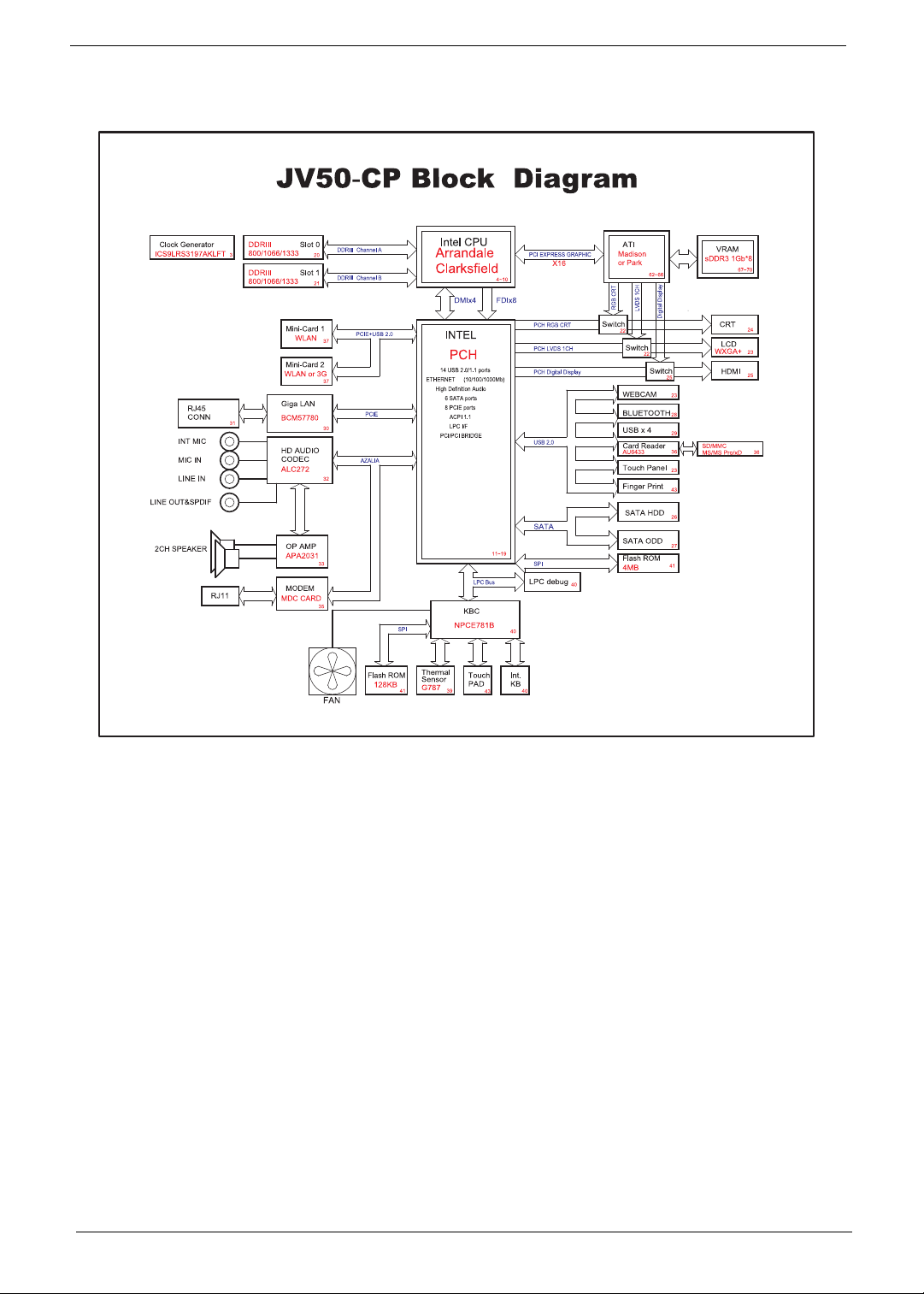
System Block Diagram
4 Chapter 1
Your Acer Notebook tour
After setting up your computer as illustrated in the Just for Starters... poster, let us show you around your new
Acer notebook.
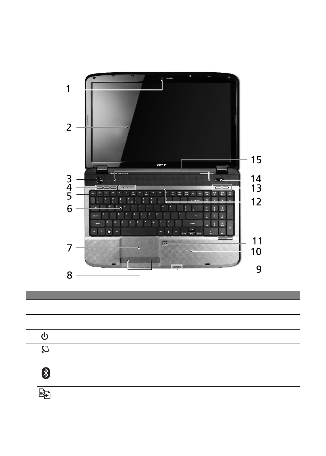
Top View
# Icon Item Description
1 Acer Crystal Eye
webcam
2 Display screen Also called Liquid-Crystal Display (LCD), displays computer output (configuration
3 Power button Turns the computer on and off.
4 Wireless LAN
communication
button/indicator
Bluetooth
communication
button/indicator
Backup key Launches Acer Backup Management for three-step data backup.
Web camera for video communication
may vary by model).
Enables/disables the wireless LAN function. Indicates the status of wireless LAN
communication.
Enables/disables the Bluetooth function. Indicates the status of Bluetooth
communication
*
.
*
.
Chapter 1 5
# Icon Item Description
5 HDD Indicates when the hard disk drive is active.
Num Lock Lights up when Num Lock is activated.
Caps Lock Lights up when Caps Lock is activated.
6 Keyboard For entering data into your computer.
7 Touchpad Touch-sensitive pointing device which functions like a computer mouse.
8 Click buttons (left
and right)
9
Power
1
The left and right buttons function like the left and right mouse buttons.
Indicates the computer's power status.
1
Battery
10 Palmrest Comfortable support area for your hands when you use the computer.
11 Touchpad toggle Turns the internal touchpad on and off.
12 Microphone Internal microphone for sound recording.
13 VOL +/- Volume Up/Volume
Down
14 P Programmable key Launch user-defined programs at a push of a button.
15 Speakers Left and right speakers deliver stereo audio output.
Indicates the computer's battery status.
1. Charging: The light shows amber when the battery is charging.
2. Fully charged: The light shows blue when in AC mode.
Increase/decrease system volume.
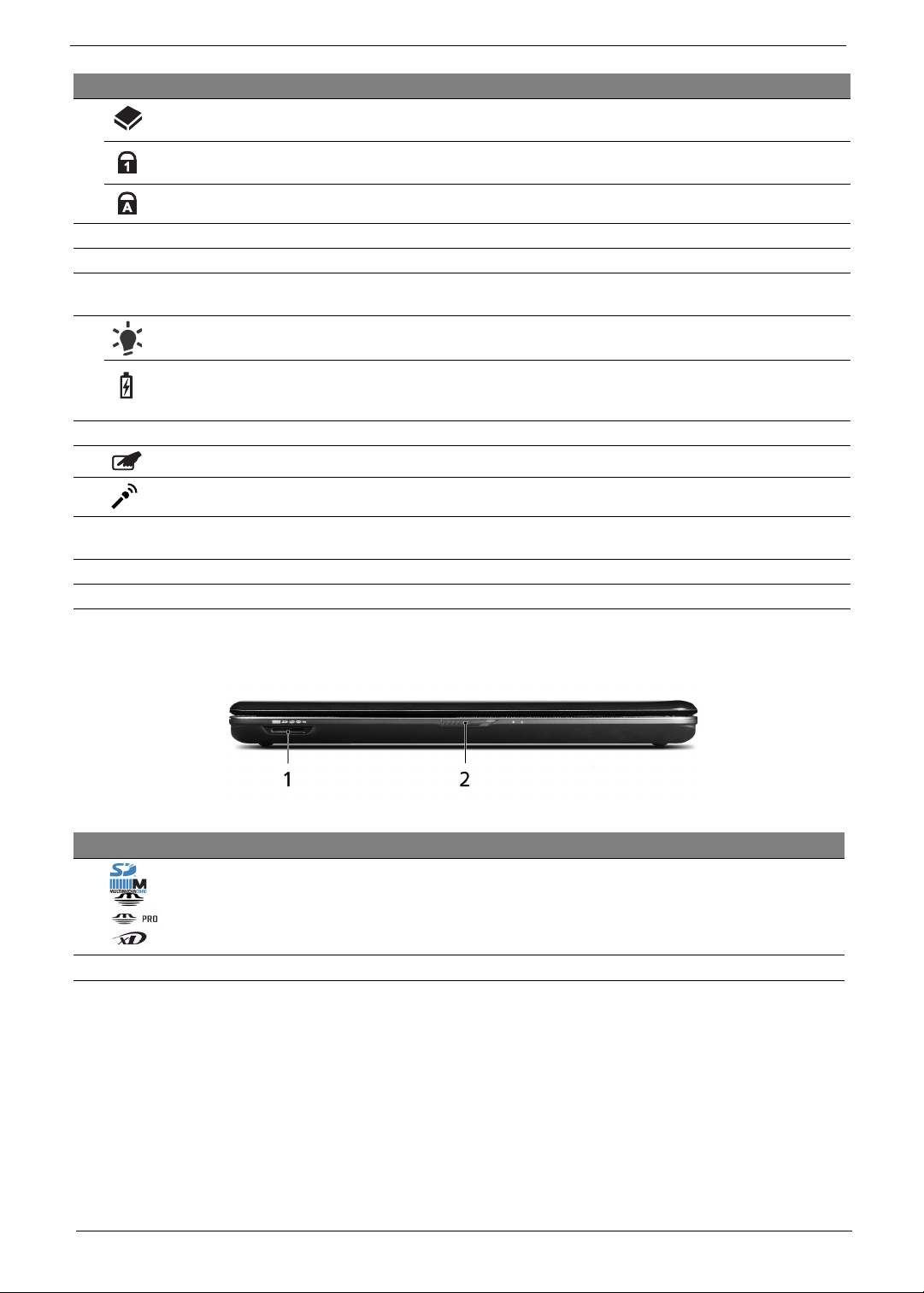
Closed front view
# Icon Item Description
1 Multi-in-1 card
reader
Accepts Secure Digital (SD), MultiMediaCard (MMC), Memory Stick
(MS), Memory Stick PRO (MS PRO), xD-Picture Card (xD).
Note: Push to remove/install the card. Only one card can operate at any
given time.
2 Latch Locks and releases the lid.
6 Chapter 1
Rear view
# Item Description
1 Ventilation slots Enable the computer to stay cool, even after prolonged use.
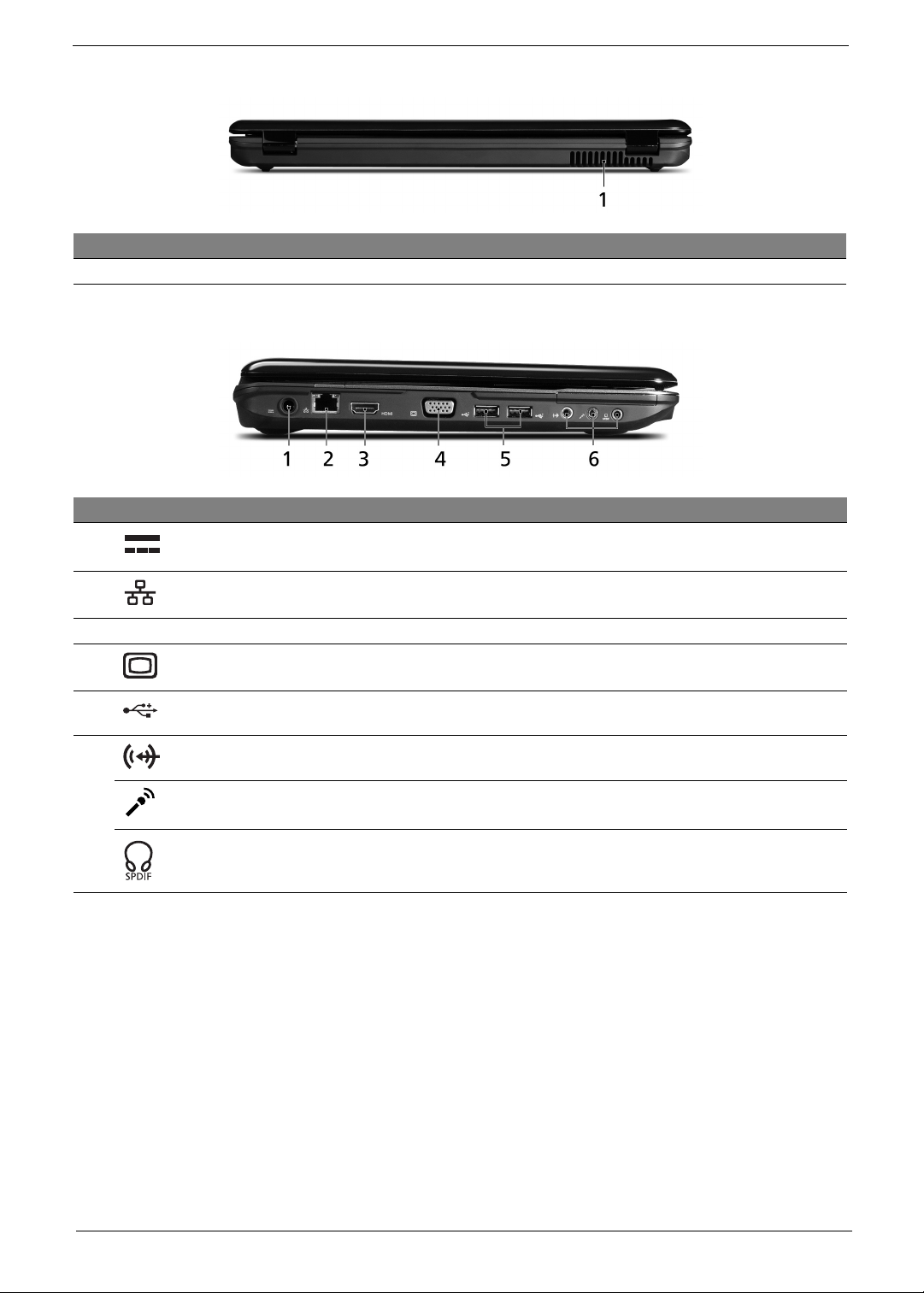
Left view
# Icon Item Description
1 DC-in jack Connects to an AC adapter.
2 Ethernet (RJ-45) port Connects to an Ethernet 10/100/1000-based network.
3 HDMI HDMI port Supports high definition digital video connections.
4 External display (VGA) port Connects to a display device (e.g., external monitor, LCD
projector).
5 USB 2.0 ports Connect to USB 2.0 devices (e.g., USB mouse, USB
camera).
6 Line-in jack Accepts audio line-in devices (e.g., audio CD player, stereo
walkman, mp3 player).
Microphone-in jack
Headphone/speaker/line-out jack
with
S/PDIF support
Accepts inputs from external microphones.
Connects to audio line-out devices
(e.g., speakers, headphones).
Chapter 1 7
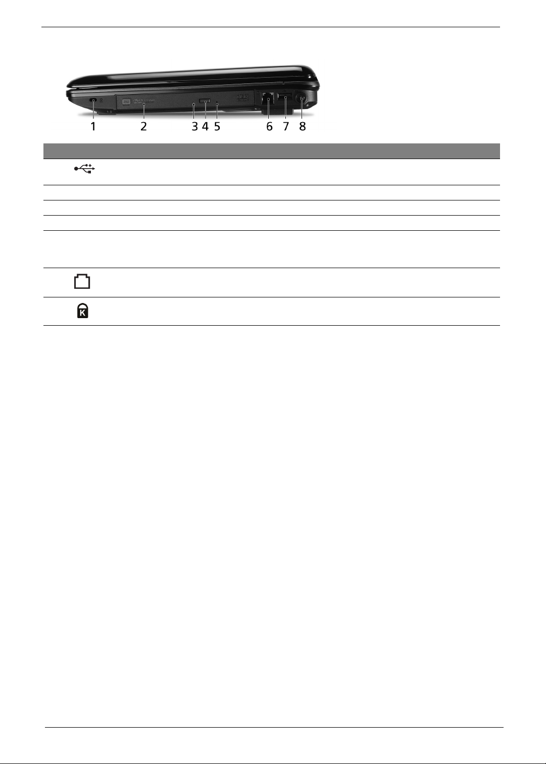
Right view
# Icon Item Description
1 USB 2.0 ports Connect to USB 2.0 devices
(e.g., USB mouse, USB camera).
2 Optical drive Internal optical drive; accepts CDs or DVDs.
3 Optical disk access indicator Lights up when the optical drive is active.
4 Optical drive eject button Ejects the optical disk from the drive.
5 Emergency eject hole Ejects the optical drive tray when the computer is turned off.
Note: Insert a paper clip to the emergency eject hole to eject
the optical drive tray when the computer is off.
6 Modem (RJ-11) port Connects to a phone line.
7 Kensington lock slot Connects to a Kensington-compatible computer security lock.
8 Chapter 1
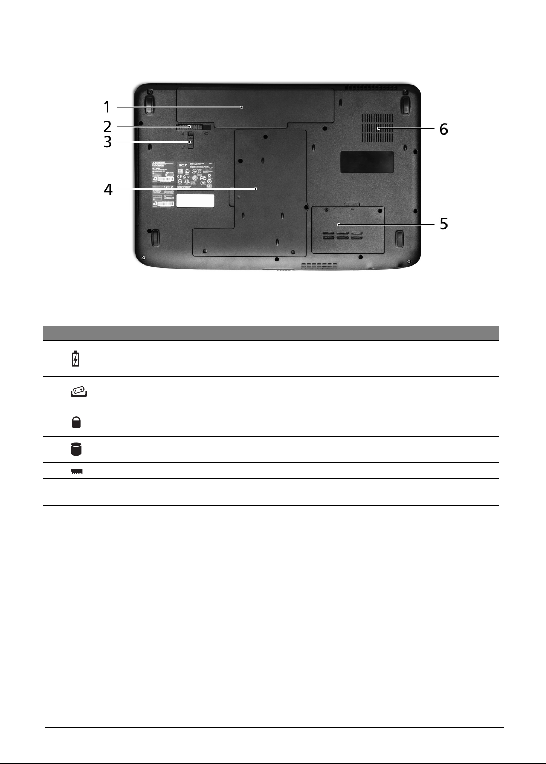
Base view
# Icon Item Description
1 Battery bay Houses the computer's battery pack.
2 Battery release latch Releases the battery for removal.
3 Battery lock Locks the battery in position.
4 Hard disk bay Houses the computer's hard disk (secured with screws).
5 Memory compartment Houses the computer's main memory.
6 Ventilation slots and cooling
fan
Enable the computer to stay cool, even after prolonged use.
Note: Do not cover or obstruct the opening of the fan.
Chapter 1 9
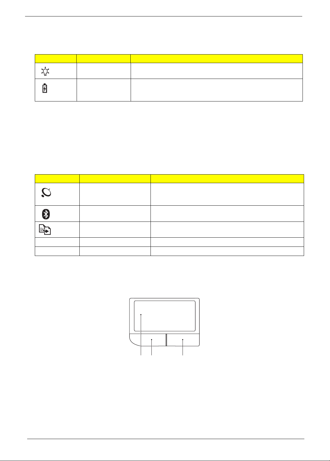
Indicators
The computer has several easy-to-read status indicators. The front panel indicators are visible even when the
computer cover is closed.
Icon Function Description
Power Indicates the computer's power status.
Battery Indicates the computer's battery status.
1. Charging: The light shows amber when the battery is charging.
2. Fully charged: The light shows blue when in AC mode.
Easy-Launch Buttons
Located above the keyboard are application buttons. These buttons are called easy-launch buttons. They are:
WLAN, Internet, email, Bluetooth, Arcade and Acer Empowering Technology.
The mail and Web browser buttons are pre-set to email and Internet programs, but can be reset by users. To
set the Web browser, mail and programmable buttons, run the Acer Launch Manager.You can access the
Launch Manager by clicking on Start, All Programs, and then Launch Manager to start the application.
Icon Function Description
Wireless LAN
communication button/
indicator
Bluetooth communication
button/indicator
Backup key Launches Acer Backup Management for three-step data
VOL+ Volume up Increases the sound volume.
VOL- Volume down Decreases the sound volume.
Enables/disables the wireless LAN function. Indicates the
status of wireless LAN communication.
Enables/disables the Bluetooth function. Indicates the status
of Bluetooth communication. (only for certain models)
backup.
Touchpad basics (with two-click buttons)
The following items show you how to use the touchpad with two-click buttons.
1 23
• Move your finger across the touchpad (1) to move the cursor.
• Press the left (2) and right (3) buttons located beneath the touchpad to perform selection and execution
functions. These two buttons are similar to the left and right buttons on a mouse. Tapping on the
touchpad is the same as clicking the left button.
10 Chapter 1
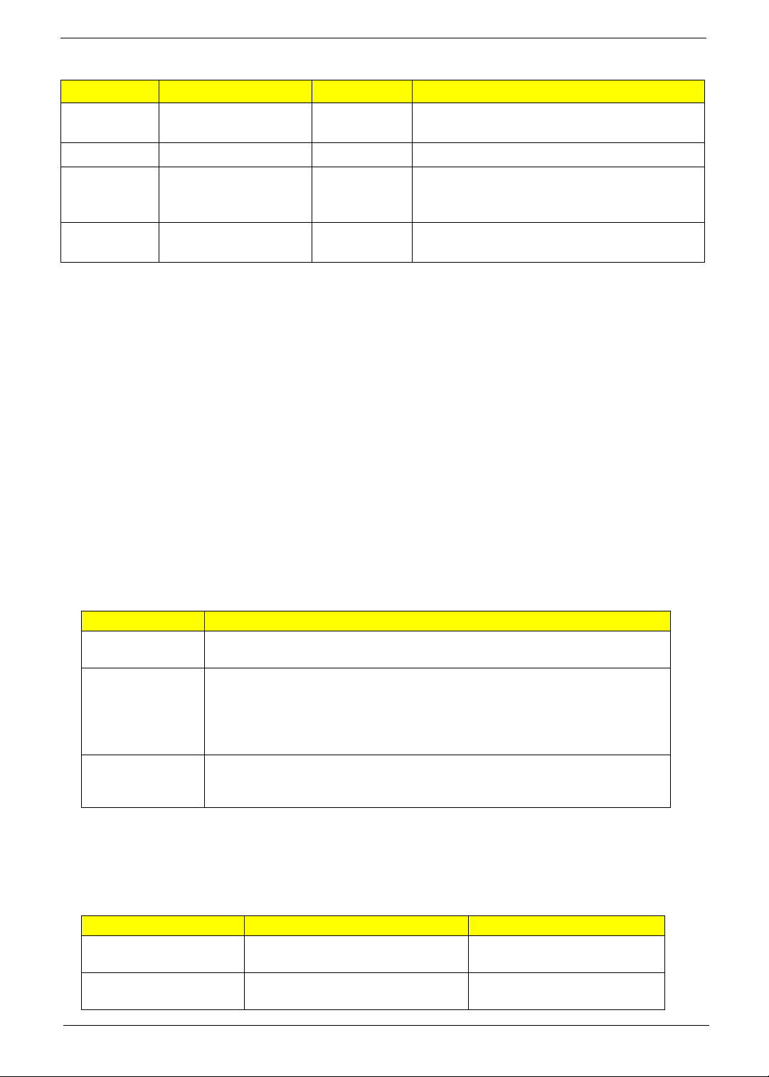
Function Left button (2) Right button (3) Main touchpad (1)
Execute Quickly click twice. Tap twice (at the same speed as double-clicking
a mouse button).
Select Click once. Tap once.
Drag Click and hold, then use
finger on the touchpad
to drag the cursor.
Access
context menu
NOTE: Illustrations are for reference only. The exact configuration of your PC depends on the model
purchased.
NOTE: When using the touchpad, keep it — and your fingers — dry and clean. The touchpad is sensitive to
finger movement; hence, the lighter the touch, the better the response. Tapping harder will not increase
the touchpad's responsiveness.
NOTE: By default, vertical and horizontal scrolling is enabled on your touchpad. It can be disabled under
Mouse settings in Windows Control Panel.
Click once.
Tap twice (at the same speed as double-clicking
a mouse button); rest your finger on the touchpad
on the second tap and drag the cursor.
Using the Keyboard
The keyboard has full-sized keys and an embedded numeric keypad, separate cursor, lock, Windows, function
and special keys.
Lock Keys and embedded numeric keypad
The keyboard has three lock keys which you can toggle on and off.
Lock key Description
Caps Lock When Caps Lock is on, all alphabetic characters typed are
in uppercase.
Num Lock
<Fn> + <F11>
Scroll Lock <Fn> +
<F12>
The embedded numeric keypad functions like a desktop numeric keypad. It is indicated by small characters
located on the upper right corner of the key caps. To simplify the keyboard legend, cursor-control key symbols
are not printed on the keys.
Desired access Num Lock on Num Lock off
Number keys on
embedded keypad
Cursor-control keys on
embedded keypad
When Num Lock is on, the embedded keypad is in numeric mode. The keys
function as a calculator (complete with the arithmetic operators +, -, *, and /).
Use this mode when you need to do a lot of numeric data entry. A better solution
would be to connect an external keypad.
NOTE: <Fn> + <F11> works only for certain models.
When Scroll Lock is on, the screen moves one line up or down when you press
the up or down arrow keys respectively. Scroll Lock does not work with some
applications.
Type numbers in a normal manner.
Hold <Shift> while using cursorcontrol keys.
Hold <Fn> while using cursorcontrol keys.
Chapter 1 11
Desired access Num Lock on Num Lock off
Main keyboard keys Hold <Fn> while typing letters on
embedded keypad.
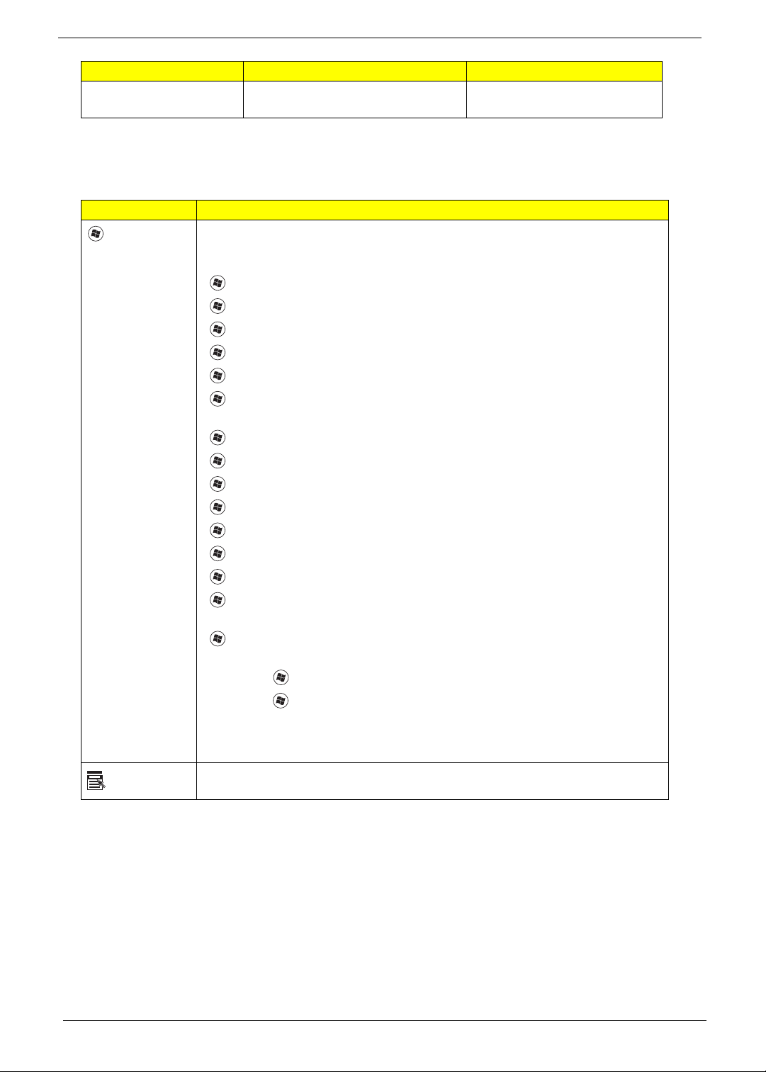
Windows Keys
The keyboard has two keys that perform Windows-specific functions.
Key Description
Windows
key
Application
key
Pressed alone, this key has the same effect as clicking on the Windows Start
button; it launches the Start menu.
It can also be used with other keys to provide a variety of functions:
< >: Open or close the Start menu
< > + <D>: Display the desktop
< > + <E>: Open Windows Explore
< > + <F>: Search for a file or folder
< > + <G>: Cycle through Sidebar gadgets
< > + <L>: Lock your computer (if you are connected to a network domain), or
switch users (if you're not connected to a network domain)
< > + <M>: Minimizes all windows
< > + <R>: Open the Run dialog box
< > + <T>: Cycle through programs on the taskbar
< > + <U>: Open Ease of Access Center
< > + <X>: Open Windows Mobility Center
< > + <BREAK>: Display the System Properties dialog box
< > + <SHIFT+M>: Restore minimized windows to the desktop
< > + <TAB>: Cycle through programs on the taskbar by using Windows Flip 3-
D
< > + <SPACEBAR>: Bring all gadgets to the front and select Windows
Sidebar
<CTRL> + < > + <F>: Search for computers (if you are on a network)
<CTRL> + < > + <TAB>: Use the arrow keys to cycle through programs on the
taskbar by using Windows Flip 3-D
Note: Depending on your edition of Windows Vista, some shortcuts may not
function as described.
This key has the same effect as clicking the right mouse button; it opens the
application's context menu.
Type the letters in a normal
manner.
12 Chapter 1
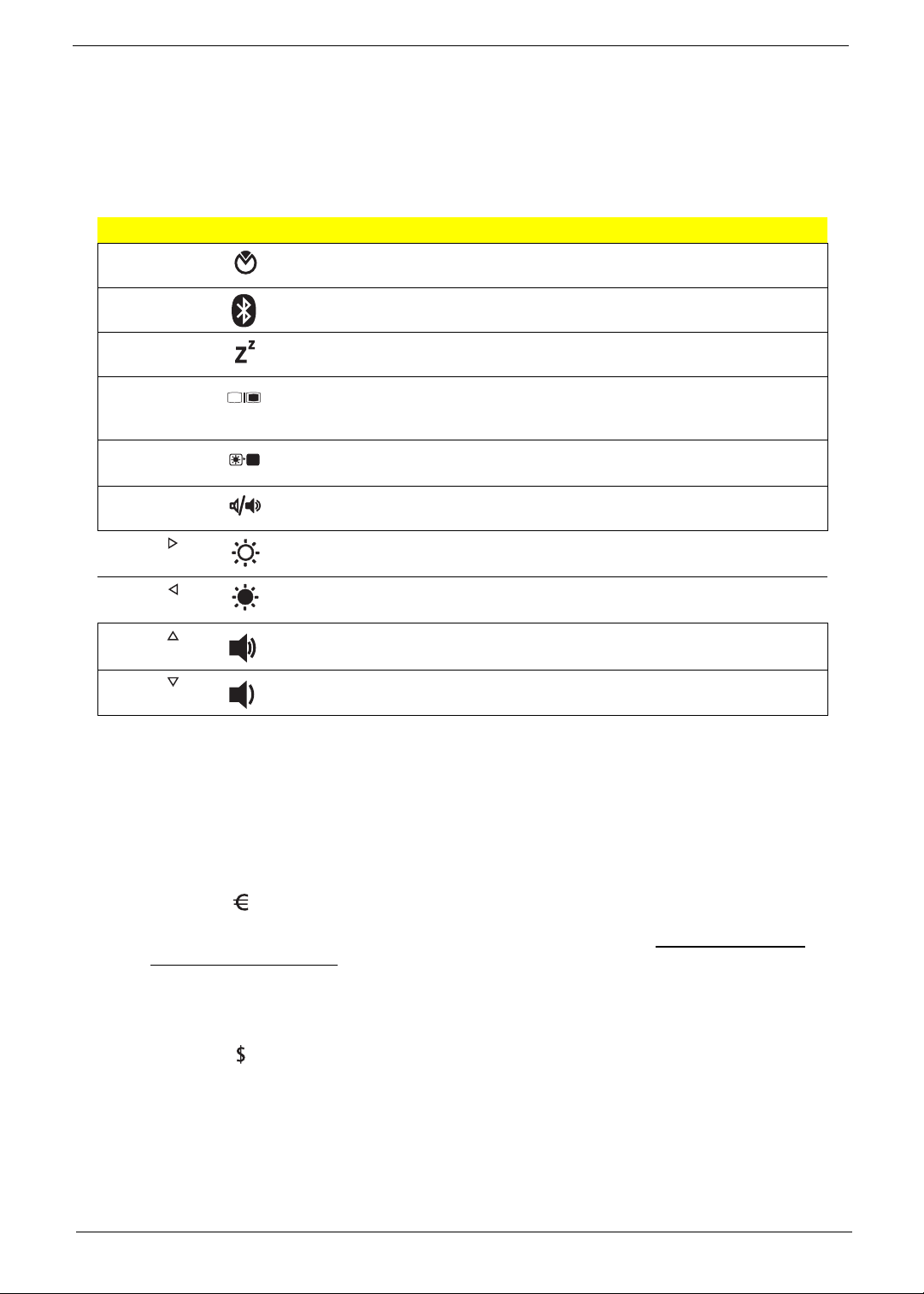
Hot Keys
The computer employs hotkeys or key combinations to access most of the computer’s controls like screen
brightness, volume output and the BIOS utility.
To activate hot keys, press and hold the <Fn> key before pressing the other key in the hotkey combination.
Hotkey Icon Function Description
<Fn> + <F2> System Properties Starts System Properties for displaying system
information.
<Fn> + <F3> Bluetooth Enables/disables the Bluetooth function.
<Fn> + <F4> Sleep Puts the computer in Sleep mode.
<Fn> + <F5> Display toggle Switches display output between the display
screen, external monitor
(if connected) and both.
<Fn> + <F6> Screen blank Turns the display screen backlight off to save
power. Press any key to return.
<Fn> + <F8> Speaker toggle Turns the speakers on and off.
<Fn> + < > Brightness up Increases the screen brightness.
<Fn> + < > Brightness down Decreases the screen brightness.
<Fn> + < > Volume up Increases the sound volume.
<Fn> + < > Volume down Decreases the sound volume.
Special Key (only for certain models)
You can locate the Euro symbol and the US dollar sign at the upper-center and/or bottom-right of your
keyboard.
The Euro symbol
1. Open a text editor or word processor.
2. Either press < > on the keyboard, or hold <Alt Gr> and then press the <5> key at the upper-center of
the keyboard.
NOTE: Some fonts and software do not support the Euro symbol. Please refer to www.microsoft.com/
typography/faq/faq12.htm for more information.
The US dollar sign
1. Open a text editor or word processor.
2. Either press < > at the bottom-right of the keyboard, or hold <Shift> and then press the <4> key at the
upper-center of the keyboard.
NOTE: This function varies according to the language settings.
Chapter 1 13
Hardware Specifications and Configurations
Processor
Item Specification
CPU type
Aspire 5740: Intel
Aspire 5740G: Intel
Intel
Intel
Core logic PCH/HM55 Express chipset
CPU package PGA 988
CPU core voltage
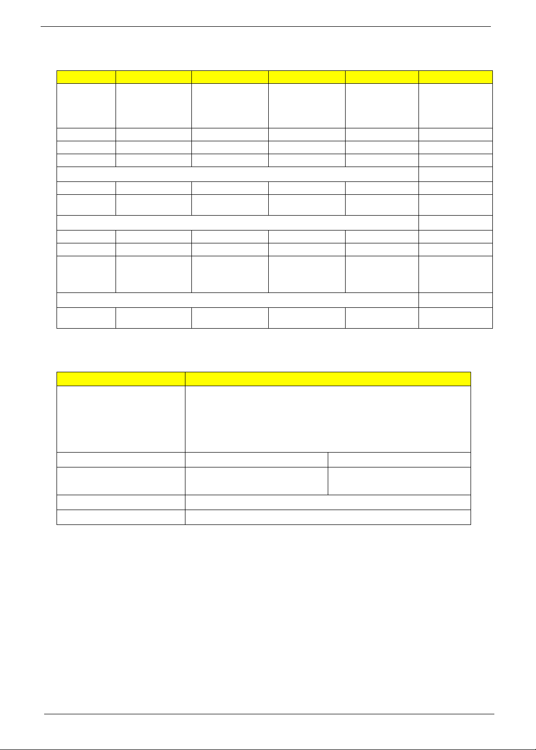
CPU Fan True Value Table
DTS(degree C) Fan Speed (rpm) Acoustic Level (dBA)
45-50 0-3000 29
55-66 0-3300 33
68-74 3300-3800 38
78-83 3800-4100 40
86-91 4100-4800 40
Throttling 50%: On= 99 C; OFF=93 C
®
Core i5 540M 2.53G 3M
®
Core i3 330M PGA 2.13G 3M
®
Core i5 520M 2.4G 3M
®
Core i5 540M 2.53G 3M
OS shut down at 105 C; H/W shot down at 110 .C
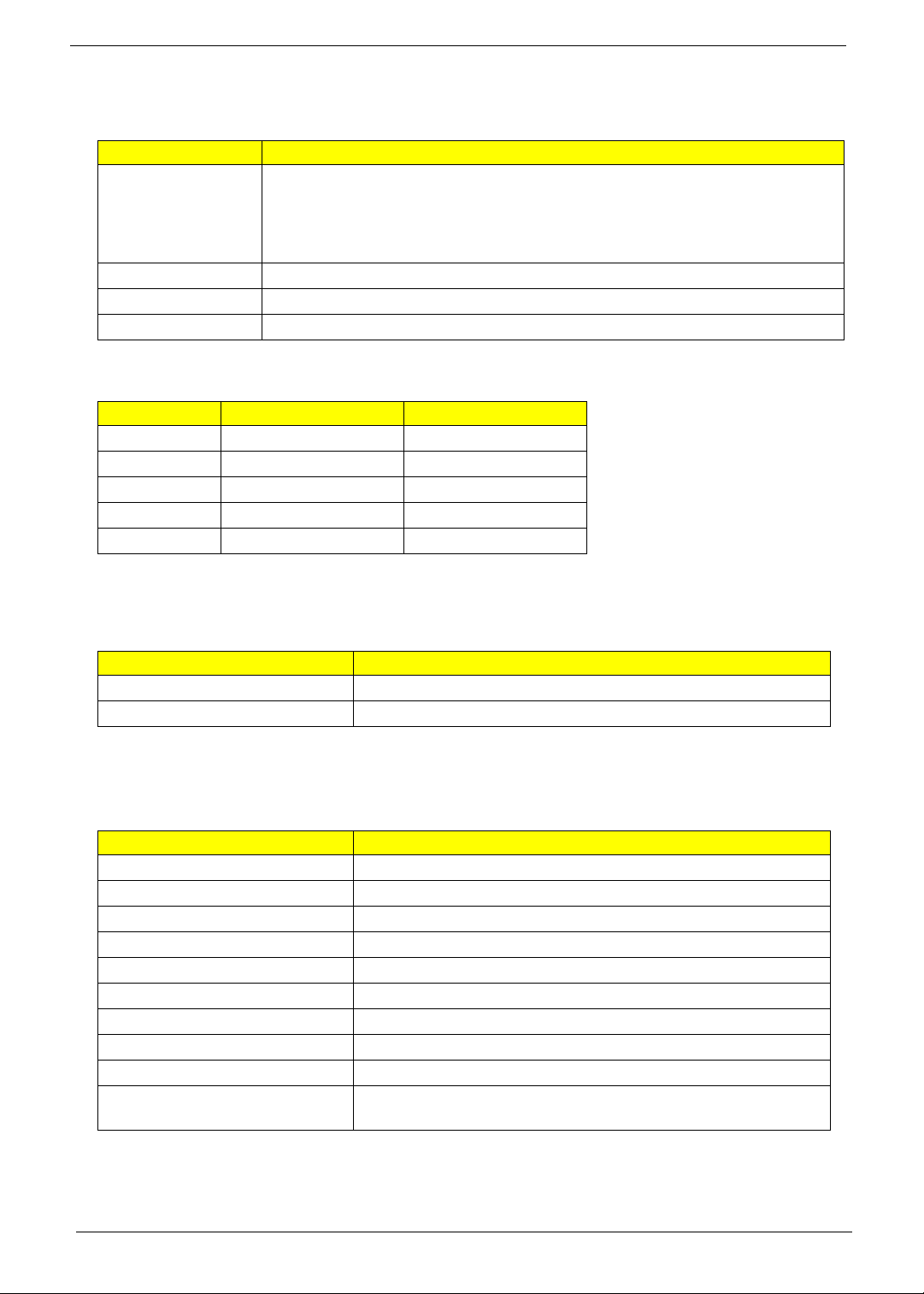
BIOS
Item Specification
BIOS vendor
BIOS Version
System Memory
Item Specification
Memory controller Built-in
Memory size 0MB (no on-board memory)
DIMM socket number 2 sockets
Supports memory size per socket 2048MB
Supports maximum memory size 4G for 64bit OS (with two 2GB SODIMM)
Supports DIMM type DDR 3 synchronous DRAM
Supports DIMM Speed 1066
Supports DIMM voltage 1.5V
Supports DIMM package 240-pin soDIMM
Memory module combinations You can install memory modules in any combinations as long as
they match the above specifications.
14 Chapter 1
Memory Combinations
Slot 1 Slot 2 Total Memory
0MB 1024MB 1024MB
0MB 2048MB 2048MB
1024MB 0MB 1024MB
1024MB 1024MB 2048MB
1024MB 2048MB 3072MB
2048MB 0MB 2048MB
2048MB 1024MB 3072MB
2048MB 2048MB 4096MB
NOTE: Above table lists some system memory configurations. You may combine DIMMs with various
capacities to form other combinations. On above table, the configuration of slot 1 and slot 2 could be
reversed.
LAN Module
Item Specification
LAN Chipset Broadcom 57780
Supports LAN protocol 10/100/1000 Mbps
LAN connector type RJ45
LAN connector location Left side
Features Integrated 10/100 BASE-T transceiver
Wake on LAN support compliant with ACPI 2.0
PCI v2.2
Bluetooth Interface
Item Specification
Chipset Foxconn Bluetooth BRM 2046 BT2.1 (T60H928.33) f/w:861
Data throughput 723 bps (full speed data rate)
Protocol Bluetooth 2.1
Interface USB 1.1
Connector type USB
Wireless Module 802.11b/g/n
Item Specification
Chipset QMI Wireless LAN Atheros HB93 1x2 BGN (HM) EM306;
LAN Intel WLAN INT1000HBG;
Foxconn Wirelss LAN Atheros HB95 1x1 BG (HM)
Data throughput 11~54 Mbps, up to 300Mbps
Protocol 802.11 b/g/n
Interface PCI Express ® mini-card rev. 1.2
Channel spacing 5MHz
Operation voltage 3.3V ± 5%
Chapter 1 15
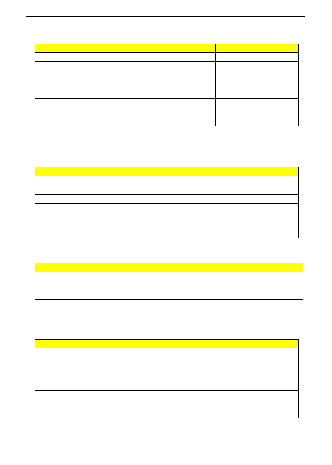
Hard Disk Drive Interface
Item
Vendor & Model
Name
Capacity (MB) 160000 250000 320000 500000 640000
Bytes per sector 512 512 512 512 512
Data heads 3/4 2 3 4
Drive Format
Disks 2 1 2 2
Spindle speed
(RPM)
Performance Specifications
Buffer size 8MB 8MB 8MB 8MB 8MB
In ter face S ATA SATA SATA SATA SATA
Max. media
transfer rate
(disk-buffer,
Mbytes/s)
DC Power Requirements
Voltage
tolerance
2.5" 5400rpm 160GB
HGST
HTS545016B9A300
WD WD1600BEVT22ZCTO
5400 RPM 5400 RPM 5400 RPM 5400 RPM 5400 rpm
540 875
5V(DC) +/- 5% 5V(DC) +/- 5% 5V(DC) +/- 5% 5V(DC) +/- 5% 5V(DC) +/- 5%
2.5" 5400rpm 250GB
HGST
HTS545025B9A300
WD WD2500BEVT22ZCT0
(Max. 3.0 Gbit/s
Buffer-host data
transfer)
2.5" 5400rpm 320GB
HGST
HTS545032B9A300
WD WD3200BEVT22ZCT0
875
(Max. 3.0 Gbit/s
Buffer-host data
transfer)
2.5" 5400rpm 500GB
HGST
HTS545050B9A300
WD WD5000BEVT22ZAT0
875
(Max. 3.0 Gbit/s
Buffer-host data
transfer)
2.5" 5400rpm 640GB
WD WD6400BEVT22A0RT0
875
(Max. 3.0 Gbit/s
Buffer-host data
transfer)
Optical Disc Drive
Item Specification
Vendor & model name HLDS Super-Multi Drive DL 8X GT30N LF
PANASONIC Super-Multi Drive DL 8X UJ890A LF
PLDS Super-Multi Drive DL 8X DS-8A4SH LF
SONY Super-Multi Drive DL 8X AD-7585H LF
TOSHIBA Super-Multi Drive DL 8X TS-L633C LF
Performance Specification With CD Diskette With DVD Diskette
Transfer rate (KB/sec) Sustained:
Max 3.6Mbytes/sec
Sustained:
Max 10.08Mbytes/sec
Buffer Memory 2MB
Interface SATA
16 Chapter 1
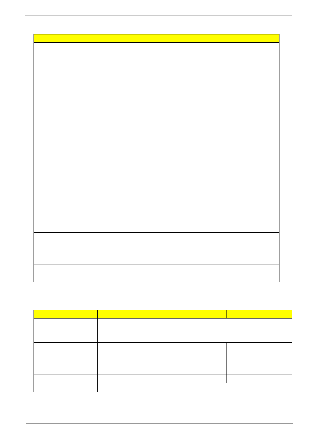
Optical Disc Drive
Item Specification
Applicable disc format Applicable disc format
CD: CD-DA, CD-ROM, CD-ROM XA, Photo CD (multi-session), Video
CD, Cd-Extra (CD+), CD-text
DVD: DVD-VIDEO, DVD-ROM, DVD-R (3.9GB, 4.7GB) DVD-R DL,
DVD-RW, DVD-RAM, DVD+R, DVD+R DL, DVD+RW
CD:
CD-DA (Red Book) - Standard Audio CD & CD-TEXT
CD-ROM (Yellow Book Mode1 & 2) - Standard Data
CD-ROM XA (Mode2 Form1 & 2) - Photo CD, Multi-Session
CD-I (Green Book, Mode2 Form1 & 2, Ready, Bridge)
CD-Extra/ CD-Plus (Blue Book) - Audio & Text/Video
Video-CD (White Book) - MPEG1 Video
CD-R (Orange Book Part)
CD-RW & HSRW (Orange Book Part Volume1 & Volume 2
Super Audio CD (SACD) Hybrid type
US & US+ RW
DVD:
DVD-ROM (Book 1.02), DVD-Dual
DVD-Video (Book 1.1)
DVD-R (Book 1.0, 3.9G)
DVD-R (Book 2.0, 4.7G) - General & Authoring
DVD+R (Version 1.0)
DVD+RW
DVD-RW (Non CPRM & CPRM)
DVD°”R Dual
Loading mechanism Load: Manual
Release: (a) Electrical Release (Release Button)
(b) Release by ATAPI command
(c) Emergency Release
Power Requirement
Input Voltage 5 V +/- 5% (Operating)
Blu-Ray Disc Drive
Item Specification
Vendor & model name HLDS BD COMBO DRIVE TRAY DL 4X CT21N LF
SONY BD COMBO DRIVE TRAY DL 4X BC-5500H LF
PLDS BD COMBO DRIVE TRAY DL 4X DS-4E1S LF
Performance
With CD Disc With DVD Disc With Blu-ray Disc
Specification
Transfer rate (KB/sec) Sustained:
Max 3.6Mbytes/sec
Sustained:
Max 10.08Mbytes/sec
Sustained:
Max 11 Mbytes/sec
Buffer Memory 2MB 4.5 MB
Interface SATA
Chapter 1 17
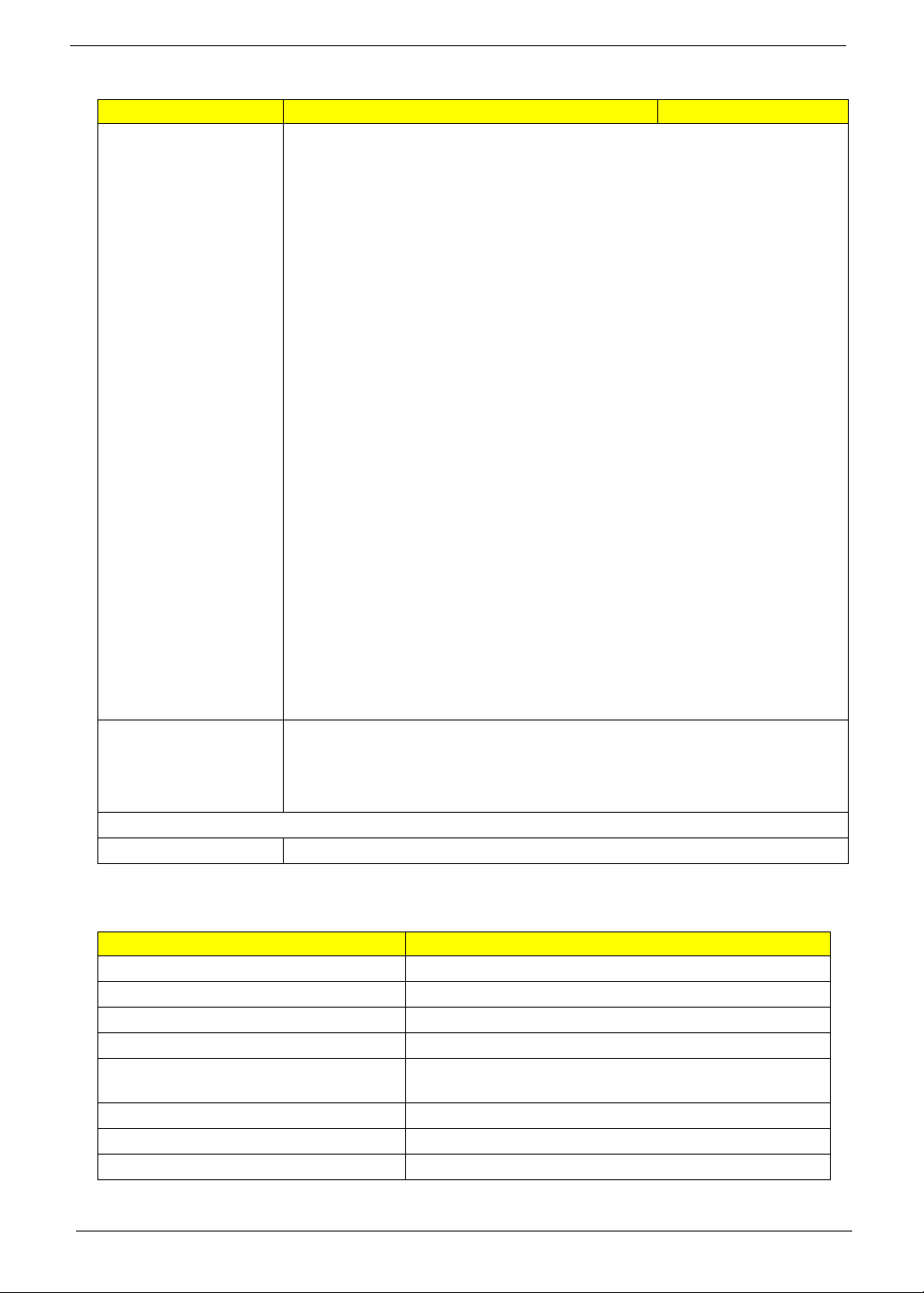
Blu-Ray Disc Drive
Item Specification
Applicable disc format Applicable disc format
CD: CD-DA, CD-ROM, CD-ROM XA, Photo CD (multi-session), Video CD, CdExtra (CD+), CD-text
DVD: DVD-VIDEO, DVD-ROM, DVD-R (3.9GB, 4.7GB) DVD-R DL, DVD-RW,
DVD-RAM, DVD+R, DVD+R DL, DVD+RW
CD:
CD-DA (Red Book) - Standard Audio CD & CD-TEXT
CD-ROM (Yellow Book Mode1 & 2) - Standard Data
CD-ROM XA (Mode2 Form1 & 2) - Photo CD, Multi-Session
CD-I (Green Book, Mode2 Form1 & 2, Ready, Bridge)
CD-Extra/ CD-Plus (Blue Book) - Audio & Text/Video
Video-CD (White Book) - MPEG1 Video
CD-R (Orange Book Part)
CD-RW & HSRW (Orange Book Part Volume1 & Volume 2
Super Audio CD (SACD) Hybrid type
US & US+ RW
DVD:
DVD-ROM (Book 1.02), DVD-Dual
DVD-Video (Book 1.1)
DVD-R (Book 1.0, 3.9G)
DVD-R (Book 2.0, 4.7G) - General & Authoring
DVD+R (Version 1.0)
DVD+RW
DVD-RW (Non CPRM & CPRM)
DVD+/-R Dual
Blu-Ray:
BD-R, BD-R DL, BD-RE, BD-RE DL
Loading mechanism Load: Manual
Release: (a) Electrical Release (Release Button)
(b) Release by ATAPI command
(c) Emergency Release
Power Requirement
Input Voltage 5 V +/- 5% (Operating)
Audio Interface
Item Specification
Audio Controller Realtek ALC272
Audio onboard or optional Built-in
Mono or Stereo Stereo
Resolution 18 bit stereo full duplex
Compatibility HD audio Interface; S/PDIF output for PCM or AC-3
content
Sampling rate 1Hz resolution VSR (Variable Sampling Rate)
Internal microphone Yes
Internal speaker / Quantity Yes/2.1 (2W speakers)
18 Chapter 1
Video
Item Specification
Chipset UMA
AMD PARK_XT 40nm 29mm*29mm M2 package
AMD MADISON_PRO 40nm 29mm*29mm M2 package
Memory size 1 GB DDR3
System Board Major Chips
Item Controller
PCH IC PCH HM55 QMNT MM#904529 B3
MODEM Foxconn Delphi-AM5 V2H 1.5_3.3V AUS T60M951.36
Lite-On Conexant -Unizion1.5_3.3V AUS B85247600G
Bluetooth Foxconn Bluetooth BCM2046 V2.11
Wireless 802.11 b/g/n Foxconn Atheros XB63
QMI Atheros HB93 1X2 BGN HM EM306
Foxconn 802.11BGN BCM 43225 BGN
5 in 1 Card Reader AU6433
Audio Codec Realtek ALC272
Keyboard
Item Specification
Keyboard controller NPCE781B
Total number of keypads 103-/104-/107-key keyboard
Windows logo key Yes
Internal & external keyboard work
Plug USB keyboard to the USB port directly: Yes
simultaneously
Battery
Item Specification
Vendor Panasonic/Sony/Sanyo/Simplo
Battery Type Li-ion
Pack capacity 6-cell 4400mAh
Number of battery cell 6
Package configuration 3 cells in series, 2 series in parallel/
LCD 15.6” inches
Item Specification
Vendor & model name AUO/CMO/LG/Samsung
Screen Diagonal (mm) 15.6 inches
Display resolution (pixels) 15.6" WXGA Glare
Pixel Pitch 0.204 x 0.204
Pixel Arrangement R.G.B. Vertical Stripe
Chapter 1 19
LCD 15.6” inches
Item Specification
Display Mode Normally White
Typical White Luminance (NIT)
220
also called Brightness
Luminance Uniformity 1.25 max.
Contrast Ratio 400 typical
Response Time msec 8
Nominal Input Voltage VDD +3.3V
Viewing Angle (degree)
Horizontal: Right/Left
Vertical: Upper/Lower
45/45
15/35
Temperature Range( C)
Operating
Storage (shipping)
0 to +50
-40 to +60
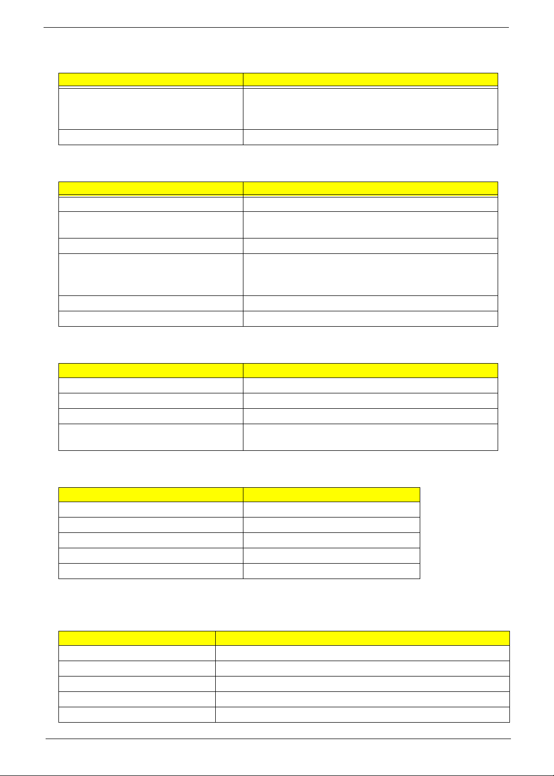
AC Adaptor
Item Specification
Input 100-240V~ 1.5A, 50-60Hz/
Output 65W 19V
System Power Management
ACPI mode Power Management
Mech. Off (G3) All devices in the system are turned off completely.
Soft Off (G2/S5) OS initiated shutdown. All devices in the system are turned
off completely.
Working (G0/S0) Individual devices such as the CPU and hard disc may be
power managed in this state.
Suspend to RAM (S3) CPU set power down
VGA Suspend
PCMCIA Suspend
Audio Power Down
Hard Disk Power Down
CD-ROM Power Down
Super I/O Low Power mode
Save to Disk (S4) Also called Hibernation Mode. System saves all system
states and data onto the disc prior to power off the whole
system.
20 Chapter 1
Chapter 2
System Utilities
BIOS Setup Utility
The BIOS Setup Utility is a hardware configuration program built into your computer’s BIOS (Basic Input/
Output System).
Your computer is already properly configured and optimized, and you do not need to run this utility. However, if
you encounter configuration problems, you may need to run Setup. Please also refer to Chapter 4
Troubleshooting when problem arises.
To activate the BIOS Utility, press F2 during POST (when “Press <F2> to enter Setup” message is prompted
on the bottom of screen).
Press F2 to enter setup. The default parameter of F12 Boot Menu is set to “disabled”. If you want to change
boot device without entering BIOS Setup Utility, please set the parameter to “enabled”.
Press <F12> during POST to enter multi-boot menu. In this menu, user can change boot device without
entering BIOS SETUP Utility.
Chapter 2 21

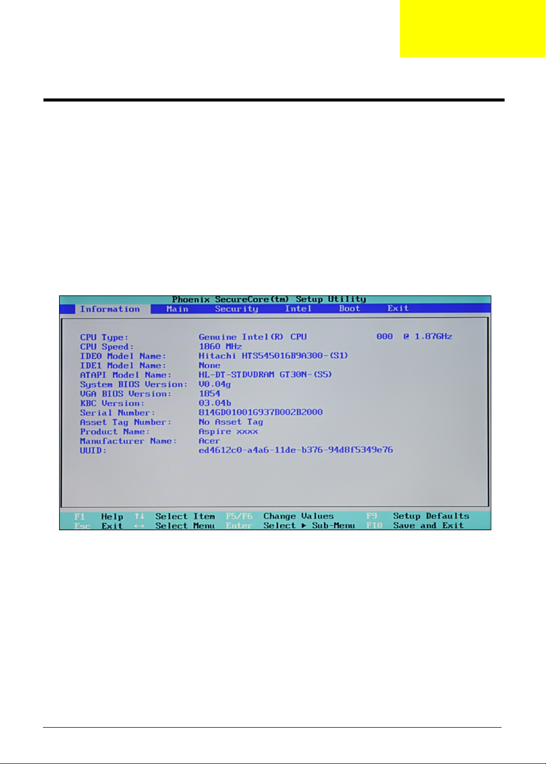
Navigating the BIOS Utility
There are five menu options: Information, Main, Security, Boot, and Exit.
Follow these instructions:
• To choose a menu, use the left and right arrow keys.
• To choose an item, use the up and down arrow keys.
• To change the value of a parameter, press F5 or F6.
• A plus sign (+) indicates the item has sub-items. Press Enter to expand this item.
• Press Esc while you are in any of the menu options to go to the Exit menu.
• In any menu, you can load default settings by pressing F9. You can also press F10 to save any
changes made and exit the BIOS Setup Utility.
NOTE: You can change the value of a parameter if it is enclosed in square brackets. Navigation keys for a
particular menu are shown on the bottom of the screen. Help for parameters are found in the Item
Specific Help part of the screen. Read this carefully when making changes to parameter values. Please
note that system information is subject to different models.
22 Chapter 2
 Loading...