


Aspire 5739 Series
Service Guide
Service guide files and updates are available
on the ACER/CSD web; for more information,
please refer to http://csd.acer.com.tw
PRINTED IN TAIWAN

Revision History
Please refer to the table below for the updates made to this service guide.
Date Chapter Updates
II

Copyright
Copyright © 2009 by Acer Incorporated. All rights reserved. No part of this publication may be reproduced,
transmitted, transcribed, stored in a retrieval system, or translated into any language or computer language, in
any form or by any means, electronic, mechanical, magnetic, optical, chemical, manual or otherwise, without
the prior written permission of Acer Incorporated.
Disclaimer
The information in this guide is subject to change without notice.
Acer Incorporated makes no representations or warranties, either expressed or implied, with respect to the
contents hereof and specifically disclaims any warranties of merchantability or fitness for any particular
purpose. Any Acer Incorporated software described in this manual is sold or licensed "as is". Should the
programs prove defective following their purchase, the buyer (and not Acer Incorporated, its distributor, or its
dealer) assumes the entire cost of all necessary servicing, repair, and any incidental or consequential
damages resulting from any defect in the software.
Acer is a registered trademark of Acer Corporation.
Intel is a registered trademark of Intel Corporation.
Pentium and Pentium II/III are trademarks of Intel Corporation.
Other brand and product names are trademarks and/or registered trademarks of their respective holders.
III

Conventions
The following conventions are used in this manual:
SCREEN MESSAGES Denotes actual messages that
NOTE Gives bits and pieces of additional
WARNING Alerts you to any damage that might
CAUTION Gives precautionary measures to
IMPORTANT Reminds you to do specific actions
appear on screen.
information related to the current
topic.
result from doing or not doing
specific actions.
avoid possible hardware or software
problems.
relevant to the accomplishment of
procedures.
IV

Preface
Before using this information and the product it supports, please read the following general information.
1. This Service Guide provides you with all technical information relating to the BASIC CONFIGURATION
decided for Acer's "global" product offering. To better fit local market requirements and enhance product
competitiveness, your regional office MAY have decided to extend the functionality of a machine (e.g.
add-on card, modem, or extra memory capability). These LOCALIZED FEATURES will NOT be covered
in this generic service guide. In such cases, please contact your regional offices or the responsible
personnel/channel to provide you with further technical details.
2. Please note WHEN ORDERING FRU PARTS, that you should check the most up-to-date information
available on your regional web or channel. If, for whatever reason, a part number change is made, it will
not be noted in the printed Service Guide. For ACER-AUTHORIZED SERVICE PROVIDERS, your Acer
office may have a DIFFERENT part number code to those given in the FRU list of this printed Service
Guide. You MUST use the list provided by your regional Acer office to order FRU parts for repair and
service of customer machines.
V

VI

Table of Contents
System Specifications 1
Features . . . . . . . . . . . . . . . . . . . . . . . . . . . . . . . . . . . . . . . . . . . . . . . . . . . . . . . . . . . .1
System Block Diagram . . . . . . . . . . . . . . . . . . . . . . . . . . . . . . . . . . . . . . . . . . . . . . . . .4
Your Acer Notebook tour . . . . . . . . . . . . . . . . . . . . . . . . . . . . . . . . . . . . . . . . . . . . . . .5
Front View . . . . . . . . . . . . . . . . . . . . . . . . . . . . . . . . . . . . . . . . . . . . . . . . . . . . . . .5
Hot Keys . . . . . . . . . . . . . . . . . . . . . . . . . . . . . . . . . . . . . . . . . . . . . . . . . . . . . . . .7
Closed Front View . . . . . . . . . . . . . . . . . . . . . . . . . . . . . . . . . . . . . . . . . . . . . . . . .7
Rear View . . . . . . . . . . . . . . . . . . . . . . . . . . . . . . . . . . . . . . . . . . . . . . . . . . . . . . .8
Left View . . . . . . . . . . . . . . . . . . . . . . . . . . . . . . . . . . . . . . . . . . . . . . . . . . . . . . . .8
Right View . . . . . . . . . . . . . . . . . . . . . . . . . . . . . . . . . . . . . . . . . . . . . . . . . . . . . . .9
Bottom View . . . . . . . . . . . . . . . . . . . . . . . . . . . . . . . . . . . . . . . . . . . . . . . . . . . .10
Touchpad Basics (with fingerprint reader) . . . . . . . . . . . . . . . . . . . . . . . . . . . . .11
Using the Keyboard . . . . . . . . . . . . . . . . . . . . . . . . . . . . . . . . . . . . . . . . . . . . . . . . . .12
Lock Keys and embedded numeric keypad . . . . . . . . . . . . . . . . . . . . . . . . . . . .12
Windows Keys . . . . . . . . . . . . . . . . . . . . . . . . . . . . . . . . . . . . . . . . . . . . . . . . . .13
Special Key . . . . . . . . . . . . . . . . . . . . . . . . . . . . . . . . . . . . . . . . . . . . . . . . . . . . .14
Using the System Utilities . . . . . . . . . . . . . . . . . . . . . . . . . . . . . . . . . . . . . . . . . . . . . .15
Acer GridVista (dual-display compatible) . . . . . . . . . . . . . . . . . . . . . . . . . . . . . .15
Hardware Specifications and Configurations . . . . . . . . . . . . . . . . . . . . . . . . . . . . . . .17
System Utilities 27
BIOS Setup Utility . . . . . . . . . . . . . . . . . . . . . . . . . . . . . . . . . . . . . . . . . . . . . . . . . . . .27
Navigating the BIOS Utility . . . . . . . . . . . . . . . . . . . . . . . . . . . . . . . . . . . . . . . . .27
Information . . . . . . . . . . . . . . . . . . . . . . . . . . . . . . . . . . . . . . . . . . . . . . . . . . . . .28
Main . . . . . . . . . . . . . . . . . . . . . . . . . . . . . . . . . . . . . . . . . . . . . . . . . . . . . . . . . .29
Security . . . . . . . . . . . . . . . . . . . . . . . . . . . . . . . . . . . . . . . . . . . . . . . . . . . . . . . .30
Boot . . . . . . . . . . . . . . . . . . . . . . . . . . . . . . . . . . . . . . . . . . . . . . . . . . . . . . . . . . .33
Exit . . . . . . . . . . . . . . . . . . . . . . . . . . . . . . . . . . . . . . . . . . . . . . . . . . . . . . . . . . .34
BIOS Flash Utility . . . . . . . . . . . . . . . . . . . . . . . . . . . . . . . . . . . . . . . . . . . . . . . . . . . .35
Using the Flash16 Utility to Update the BIOS . . . . . . . . . . . . . . . . . . . . . . . . . . .35
WinFlash Utility . . . . . . . . . . . . . . . . . . . . . . . . . . . . . . . . . . . . . . . . . . . . . . . . . .36
DOS Flash Utility . . . . . . . . . . . . . . . . . . . . . . . . . . . . . . . . . . . . . . . . . . . . . . . . .37
Remove HDD/BIOS Password Utilities . . . . . . . . . . . . . . . . . . . . . . . . . . . . . . . . . . . .40
Miscellaneous Utilities . . . . . . . . . . . . . . . . . . . . . . . . . . . . . . . . . . . . . . . . . . . . .43
Machine Disassembly and Replacement 47
Disassembly Requirements . . . . . . . . . . . . . . . . . . . . . . . . . . . . . . . . . . . . . . . . . . . .47
General Information . . . . . . . . . . . . . . . . . . . . . . . . . . . . . . . . . . . . . . . . . . . . . . . . . .48
Pre-disassembly Instructions . . . . . . . . . . . . . . . . . . . . . . . . . . . . . . . . . . . . . . .48
Disassembly Process . . . . . . . . . . . . . . . . . . . . . . . . . . . . . . . . . . . . . . . . . . . . .48
External Module Disassembly Process . . . . . . . . . . . . . . . . . . . . . . . . . . . . . . . . . . .49
External Modules Disassembly Flowchart . . . . . . . . . . . . . . . . . . . . . . . . . . . . .49
Removing the Battery Pack . . . . . . . . . . . . . . . . . . . . . . . . . . . . . . . . . . . . . . . .49
Removing the SD dummy card . . . . . . . . . . . . . . . . . . . . . . . . . . . . . . . . . . . . . .50
Removing the Lower Cover . . . . . . . . . . . . . . . . . . . . . . . . . . . . . . . . . . . . . . . .51
Removing the WLAN Module . . . . . . . . . . . . . . . . . . . . . . . . . . . . . . . . . . . . . . .52
Removing the DIMM Modules . . . . . . . . . . . . . . . . . . . . . . . . . . . . . . . . . . . . . . .53
Removing the Hard Disk Drive Module . . . . . . . . . . . . . . . . . . . . . . . . . . . . . . . .54
Removing the Optical Disk Drive Module . . . . . . . . . . . . . . . . . . . . . . . . . . . . . .55
Removing the TV Tuner . . . . . . . . . . . . . . . . . . . . . . . . . . . . . . . . . . . . . . . . . . .57
Removing the Graphics Card . . . . . . . . . . . . . . . . . . . . . . . . . . . . . . . . . . . . . . .59
Removing the RTC Battery . . . . . . . . . . . . . . . . . . . . . . . . . . . . . . . . . . . . . . . . .59
Removing the CPU . . . . . . . . . . . . . . . . . . . . . . . . . . . . . . . . . . . . . . . . . . . . . . .60
Main Unit Disassembly Process . . . . . . . . . . . . . . . . . . . . . . . . . . . . . . . . . . . . . . . . .62
VII

Table of Contents
Main Unit Disassembly Flowchart . . . . . . . . . . . . . . . . . . . . . . . . . . . . . . . . . . . .62
Removing the Hinge Covers . . . . . . . . . . . . . . . . . . . . . . . . . . . . . . . . . . . . . . . .63
Removing the Switch Cover . . . . . . . . . . . . . . . . . . . . . . . . . . . . . . . . . . . . . . . .63
Removing the Power Save Board . . . . . . . . . . . . . . . . . . . . . . . . . . . . . . . . . . . .66
Removing the Power Switch Board . . . . . . . . . . . . . . . . . . . . . . . . . . . . . . . . . .67
Removing the Keyboard . . . . . . . . . . . . . . . . . . . . . . . . . . . . . . . . . . . . . . . . . . .67
Removing the LCD Module . . . . . . . . . . . . . . . . . . . . . . . . . . . . . . . . . . . . . . . . .68
Removing the Upper Base . . . . . . . . . . . . . . . . . . . . . . . . . . . . . . . . . . . . . . . . .72
Removing the Finger Print Reader . . . . . . . . . . . . . . . . . . . . . . . . . . . . . . . . . . .75
Removing the Multifunction Board . . . . . . . . . . . . . . . . . . . . . . . . . . . . . . . . . . .77
Removing the Modem Module . . . . . . . . . . . . . . . . . . . . . . . . . . . . . . . . . . . . . .78
Removing the Bluetooth Module . . . . . . . . . . . . . . . . . . . . . . . . . . . . . . . . . . . . .80
Removing the Mainboard . . . . . . . . . . . . . . . . . . . . . . . . . . . . . . . . . . . . . . . . . .80
Removing the Thermal Module . . . . . . . . . . . . . . . . . . . . . . . . . . . . . . . . . . . . . .82
Removing the CPU (Alternate Procedure) . . . . . . . . . . . . . . . . . . . . . . . . . . . . .84
Removing the Speaker Modules . . . . . . . . . . . . . . . . . . . . . . . . . . . . . . . . . . . . .85
LCD Module Disassembly Process . . . . . . . . . . . . . . . . . . . . . . . . . . . . . . . . . . . . . .88
LCD Module Disassembly Flowchart . . . . . . . . . . . . . . . . . . . . . . . . . . . . . . . . .88
Removing the LCD Bezel . . . . . . . . . . . . . . . . . . . . . . . . . . . . . . . . . . . . . . . . . .88
Removing the Camera Module . . . . . . . . . . . . . . . . . . . . . . . . . . . . . . . . . . . . . .90
Removing the LCD Panel . . . . . . . . . . . . . . . . . . . . . . . . . . . . . . . . . . . . . . . . . .91
Removing the LCD Brackets and FPC Cable . . . . . . . . . . . . . . . . . . . . . . . . . . .92
Removing the Antennas . . . . . . . . . . . . . . . . . . . . . . . . . . . . . . . . . . . . . . . . . . .93
LCD Module Reassembly Procedure . . . . . . . . . . . . . . . . . . . . . . . . . . . . . . . . . . . . .95
Replacing the Antennas . . . . . . . . . . . . . . . . . . . . . . . . . . . . . . . . . . . . . . . . . . .95
Replacing the LCD Panel . . . . . . . . . . . . . . . . . . . . . . . . . . . . . . . . . . . . . . . . . .96
Replacing the Camera Module . . . . . . . . . . . . . . . . . . . . . . . . . . . . . . . . . . . . . .97
Replacing the LCD Bezel . . . . . . . . . . . . . . . . . . . . . . . . . . . . . . . . . . . . . . . . . .98
Main Module Reassembly Procedure . . . . . . . . . . . . . . . . . . . . . . . . . . . . . . . . . . . . .99
Replacing the Speaker Modules . . . . . . . . . . . . . . . . . . . . . . . . . . . . . . . . . . . . .99
Replacing the CPU (Alternate Procedure) . . . . . . . . . . . . . . . . . . . . . . . . . . . .100
Replacing the Thermal Module . . . . . . . . . . . . . . . . . . . . . . . . . . . . . . . . . . . . .101
Replacing the Mainboard . . . . . . . . . . . . . . . . . . . . . . . . . . . . . . . . . . . . . . . . .103
Replacing the Bluetooth Board . . . . . . . . . . . . . . . . . . . . . . . . . . . . . . . . . . . . .105
Replacing the Modem Module . . . . . . . . . . . . . . . . . . . . . . . . . . . . . . . . . . . . .107
Replacing the Finger Print Reader . . . . . . . . . . . . . . . . . . . . . . . . . . . . . . . . . .109
Replacing the Upper Cover . . . . . . . . . . . . . . . . . . . . . . . . . . . . . . . . . . . . . . . .109
Replacing the LCD Module . . . . . . . . . . . . . . . . . . . . . . . . . . . . . . . . . . . . . . . .113
Replacing the Keyboard . . . . . . . . . . . . . . . . . . . . . . . . . . . . . . . . . . . . . . . . . .116
Replacing the Power Switch Board . . . . . . . . . . . . . . . . . . . . . . . . . . . . . . . . . .116
Replacing the Power Save Board . . . . . . . . . . . . . . . . . . . . . . . . . . . . . . . . . . .117
Replacing the Switch Cover . . . . . . . . . . . . . . . . . . . . . . . . . . . . . . . . . . . . . . .118
Replacing the Hinge Covers . . . . . . . . . . . . . . . . . . . . . . . . . . . . . . . . . . . . . . .120
External Unit Reassembly Process . . . . . . . . . . . . . . . . . . . . . . . . . . . . . . . . . . . . .122
Replacing the CPU . . . . . . . . . . . . . . . . . . . . . . . . . . . . . . . . . . . . . . . . . . . . . .122
Replacing the RTC Battery . . . . . . . . . . . . . . . . . . . . . . . . . . . . . . . . . . . . . . . .123
Replacing the Graphics Card . . . . . . . . . . . . . . . . . . . . . . . . . . . . . . . . . . . . . .123
Replacing the ODD Module . . . . . . . . . . . . . . . . . . . . . . . . . . . . . . . . . . . . . . .125
Replacing the Hard Disk Drive Module . . . . . . . . . . . . . . . . . . . . . . . . . . . . . . .126
Replacing the DIMM Modules . . . . . . . . . . . . . . . . . . . . . . . . . . . . . . . . . . . . . .126
Replacing the WLAN Module . . . . . . . . . . . . . . . . . . . . . . . . . . . . . . . . . . . . . .128
Replacing the TV Tuner . . . . . . . . . . . . . . . . . . . . . . . . . . . . . . . . . . . . . . . . . .128
Replacing the Lower Cover . . . . . . . . . . . . . . . . . . . . . . . . . . . . . . . . . . . . . . . .130
Replacing the SD Card Dummy Tray . . . . . . . . . . . . . . . . . . . . . . . . . . . . . . . .130
Replacing the Battery . . . . . . . . . . . . . . . . . . . . . . . . . . . . . . . . . . . . . . . . . . . .131
VIII

Table of Contents
Troubleshooting 133
Common Problems . . . . . . . . . . . . . . . . . . . . . . . . . . . . . . . . . . . . . . . . . . . . . . . . . .133
Power On Issue . . . . . . . . . . . . . . . . . . . . . . . . . . . . . . . . . . . . . . . . . . . . . . . .134
No Display Issue . . . . . . . . . . . . . . . . . . . . . . . . . . . . . . . . . . . . . . . . . . . . . . . .136
Random Loss of BIOS Settings . . . . . . . . . . . . . . . . . . . . . . . . . . . . . . . . . . . .138
LCD Failure . . . . . . . . . . . . . . . . . . . . . . . . . . . . . . . . . . . . . . . . . . . . . . . . . . . .139
Built-In Keyboard Failure . . . . . . . . . . . . . . . . . . . . . . . . . . . . . . . . . . . . . . . . .139
Touchpad Failure . . . . . . . . . . . . . . . . . . . . . . . . . . . . . . . . . . . . . . . . . . . . . . .140
Internal Speaker Failure . . . . . . . . . . . . . . . . . . . . . . . . . . . . . . . . . . . . . . . . . .140
Internal Microphone Failure . . . . . . . . . . . . . . . . . . . . . . . . . . . . . . . . . . . . . . .142
HDD Not Operating Correctly . . . . . . . . . . . . . . . . . . . . . . . . . . . . . . . . . . . . . .144
ODD Failure . . . . . . . . . . . . . . . . . . . . . . . . . . . . . . . . . . . . . . . . . . . . . . . . . . .145
USB Failure (Rightside) . . . . . . . . . . . . . . . . . . . . . . . . . . . . . . . . . . . . . . . . . .149
Modem Function Failure . . . . . . . . . . . . . . . . . . . . . . . . . . . . . . . . . . . . . . . . . .149
Wireless Function Failure . . . . . . . . . . . . . . . . . . . . . . . . . . . . . . . . . . . . . . . . .150
Bluetooth Function Failure . . . . . . . . . . . . . . . . . . . . . . . . . . . . . . . . . . . . . . . .150
EasyTouch Button Failure . . . . . . . . . . . . . . . . . . . . . . . . . . . . . . . . . . . . . . . . .151
Media Board Failure . . . . . . . . . . . . . . . . . . . . . . . . . . . . . . . . . . . . . . . . . . . . .151
Fingerprint Reader Failure . . . . . . . . . . . . . . . . . . . . . . . . . . . . . . . . . . . . . . . .152
Thermal Unit Failure . . . . . . . . . . . . . . . . . . . . . . . . . . . . . . . . . . . . . . . . . . . . .152
External Mouse Failure . . . . . . . . . . . . . . . . . . . . . . . . . . . . . . . . . . . . . . . . . . .153
Other Failures . . . . . . . . . . . . . . . . . . . . . . . . . . . . . . . . . . . . . . . . . . . . . . . . . .153
Intermittent Problems . . . . . . . . . . . . . . . . . . . . . . . . . . . . . . . . . . . . . . . . . . . . . . . .154
Undetermined Problems . . . . . . . . . . . . . . . . . . . . . . . . . . . . . . . . . . . . . . . . . . . . . .154
POST Codes Tables . . . . . . . . . . . . . . . . . . . . . . . . . . . . . . . . . . . . . . . . . . . . . . . . .155
Sec: . . . . . . . . . . . . . . . . . . . . . . . . . . . . . . . . . . . . . . . . . . . . . . . . . . . . . . . . . .155
Memory: . . . . . . . . . . . . . . . . . . . . . . . . . . . . . . . . . . . . . . . . . . . . . . . . . . . . . .155
BDS & Specific action: . . . . . . . . . . . . . . . . . . . . . . . . . . . . . . . . . . . . . . . . . . .157
Each PEIM entry point used in 80_PORT . . . . . . . . . . . . . . . . . . . . . . . . . . . . .158
Each Driver entry point used in 80_PORT . . . . . . . . . . . . . . . . . . . . . . . . . . . .158
Each SmmDriver entry point used in 80_PORT . . . . . . . . . . . . . . . . . . . . . . . .161
Jumper and Connector Locations 163
Top View . . . . . . . . . . . . . . . . . . . . . . . . . . . . . . . . . . . . . . . . . . . . . . . . . . . . . . . . . .163
Bottom View . . . . . . . . . . . . . . . . . . . . . . . . . . . . . . . . . . . . . . . . . . . . . . . . . . . . . . .164
Clearing Password Check and BIOS Recovery . . . . . . . . . . . . . . . . . . . . . . . . . . . .165
Clearing Password Check . . . . . . . . . . . . . . . . . . . . . . . . . . . . . . . . . . . . . . . . .165
BIOS Recovery by Crisis Disk . . . . . . . . . . . . . . . . . . . . . . . . . . . . . . . . . . . . .167
FRU (Field Replaceable Unit) List 169
Aspire 5739 Exploded Diagrams . . . . . . . . . . . . . . . . . . . . . . . . . . . . . . . . . . . . . . .170
Main Module . . . . . . . . . . . . . . . . . . . . . . . . . . . . . . . . . . . . . . . . . . . . . . . . . . .170
Aspire 5739 FRU List . . . . . . . . . . . . . . . . . . . . . . . . . . . . . . . . . . . . . . . . . . . . . . . .171
Screw List . . . . . . . . . . . . . . . . . . . . . . . . . . . . . . . . . . . . . . . . . . . . . . . . . . . . .179
Model Definition and Configuration 181
Aspire 5739 Series . . . . . . . . . . . . . . . . . . . . . . . . . . . . . . . . . . . . . . . . . . . . . . . . . .181
Test Compatible Components 209
Microsoft® Windows® Vista Environment Test . . . . . . . . . . . . . . . . . . . . . . . . . . . .210
Online Support Information 215
Index 217
IX

Table of Contents
X

System Specifications
Features
Below is a brief summary of the computer’s many features:
NOTE: Items marked with * denote only selected models.
Operating System
• Genuine Windows® Vista™
Platform
• Intel® Centrino® 2 processor technology, featuring:
• Intel® Core™2 Duo processor
• Mobile Intel® PM45/GM45 Express Chipset*
• Intel® Wireless WiFi Link 5100/5300*
Chapter 1
System Memory
• Up to 2 GB of DDR3 1066 MHz memory, upgradeable
• to 4 GB using two soDIMM modules
Display
• Display
• 16:9 aspect ratio
• 14" HD 1366 x 768
TV-Tuner
• Digital TV-tuner supporting DVB-T*
Graphics
• Mobile Intel® GM45 Express Chipset*
• ATI Mobility™ Radeon HD 4570*
• NVIDIA® GeForce® GT 130M*
Storage subsystem
• 2.5" hard disk drive
• Optical drive options:
• Blu-ray Disc™/DVD-Super Multi double-layer drive*
• DVD-Super Multi double-layer drive*
• 5-in-1 card reader
Chapter 1 1

Audio
• Dolby®-optimized surround sound system with two built-in stereo speakers
• True 5.1-channel surround sound output
• High-definition audio support
• S/PDIF (Sony/Philips Digital Interface) support for digital speakers
• Acer PureZone technology with two built-in stereo microphones
• MS-Sound compatible
Communication
• Acer Video Conference, featuring:
• Integrated Acer Crystal Eye webcam*
• Acer PureZone technology
• WLAN: Intel® Wireless WiFi Link 5100/5300*
• WPAN: Bluetooth® 2.0+Enhanced Data Rate (EDR)*
• LAN: Gigabit Ethernet; Wake-on-LAN ready
• Modem: 56K ITU V.92; Wake-on-Ring ready
Dimensions and Weight
• 372 (W) x 262 (D) x 26/38.8 (H) mm(16.14 x 11.25 x 1.37/1.63 inches)
• 2.8 kg (5.07 lbs.) withone HDD and 8-cell battery pack
Privacy control
• Acer Bio-Protection fingerprint solution*
• BIOS user, supervisor, HDD passwords
• Kensington lock slot
Power subsystem
•ACPI 3.0
• • 71 W 4800 mAh*
• 48.8 W 4400 mAh
• 3-pin 65 W AC adapter*
• 3-pin 90 W AC adapter*
• ENERGY STAR®*
Special keys and controls
• 103-/104-/107-key keyboard
• Touchpad pointing device
I/O interface
• Acer Bio-Protection fingerprint reader
• 5-in-1 card reader (SD/MMC/MS/MS PRO/xD)
2 Chapter 1

• USB 2.0 ports•HDMI™ port with HDCP support
• HDMI™ port with HDCP support
• External display (VGA) port
• Consumer infrared (CIR) port
• RF-in jack*
• eSATA port
• Headphones/speaker/line-out jack with S/PDIF support
• Microphone-in jack
• Line-in jack
• Ethernet (RJ-45) port
• Modem (RJ-11) port
• DC-in jack for AC adapter
Environment
• Temperature:
• Operating: 5 °C to 35 °C
• Non-operating: -20 °C to 65 °C
• Humidity (non-condensing):
• Operating: 20% to 80%
• Non-operating: 20% to 80%
NOTE: Items marked with * denote only selected models.
NOTE: The specifications listed above are for reference only. The exact configuration of your PC depends on
the model purchased.
Chapter 1 3
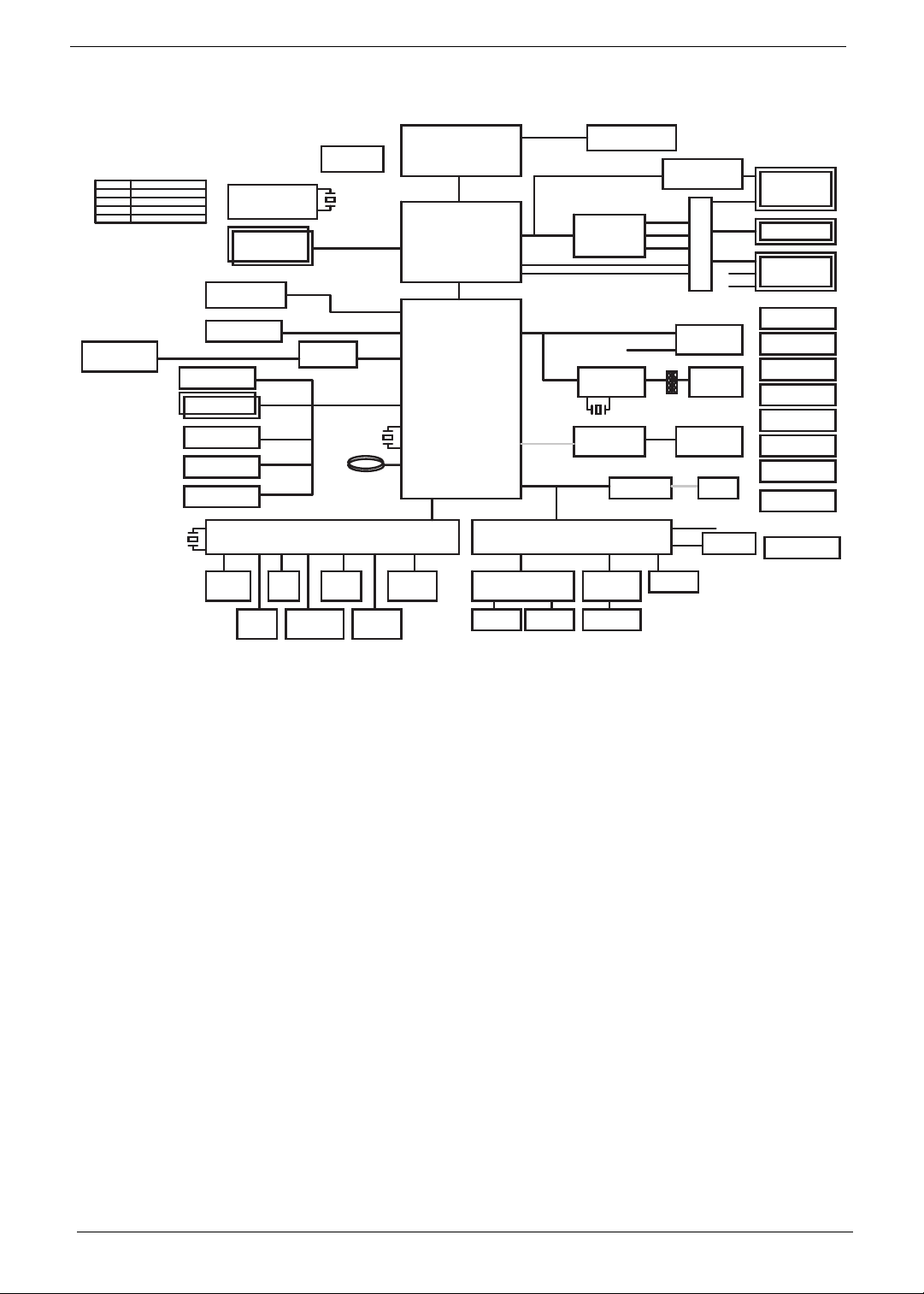
System Block Diagram
TI SN75LVCP412
Maxim 4951
Re-driver
WPC775LDG
EC
Fan Driver
X'TAL
14.318MHz
Dual Channel DDR III
800/1066 MHZ
SATA 0 & SATA 4
SATA 1
SATA 5
USB 2.0 (Port0~9)
X'TAL
32.768KHz
BATTERY
BOM Option Table
Reference
SP@
*
USB/eSATA
Description
INT VGAI@
EXT VGAE@
SPECIAL FOR EXT/INT VGA
DNI
USB-1
X'TAL
32.768KHz
SATA - HDD
SATA - ODD
CCD
USB Port x2
USB/B Con.
Bluetooth Con.
Finger Printer
SLG8SP513VTR
CLOCK GENERATOR
DDRIII-SODIMM1
DDRIII-SODIMM2
USB-6
USB-0 & USB-10
USB-4 & USB-7
USB-5
USB-9
SATA
USB
RTC
DDR SYSTEM MEMORY
PENRYN
479 uFCPGA
FSB
FSB(800/1066MHZ)
FSB
CANTIGA
NB
DMI
DMI(x4)
DMI
Intel ICH9M
SB
LPC
LPC
PCI-E
IHDA
USB
Graphics Interfaces
PCIE-2 & PCIE-4
PCIE-6
FFC cable
ALC888S-VC
AUDIO CODEC
RTS5159
Cardreader
Controller
Azalia
LM95245
Thermal Sensor
MXM 3
AR813 1
GIGA LAN
PCIE
USB-2 & USB-3
X'TAL
25MHz
MDC Con
CH7318
HDMI Level Shifter
EXT_HDMI
EXT_CRTPCI-E x16
EXT_LVDS
INT_CRT
INT_LVDS
MINI CARD
WLAN/ TV
Cardreader Con.
4 IN 1
cable
MIC
RJ45
Int. MIC
SWITCH CIRCUIT
RJ11
WIRE CONN.
MIC JACK
USB-11
Int. MIC
HDMI Con.
CRT Con.
LVDS/CCD/MIC
Con.
THERMAL
PROTECTION
2.5V/ 1.5V PWR
DISCHARGER
ISL6251
CHARGER
ISL6237
3/5V SYS PWR
ISL6262A
CPU CORE PWR
RT8202
+1.05V
ISL6263A
+1.05V_AXG
TPS5116
DDR PWR
POWER TREE
Power
Board Con.
K/B Con.
CIR
W25X16VSS1G
SPI FLASH
MMB Board
Con.
EM-6781-T3
HALL SENSOR
Touch Pad
Board Con.
AUDIO AMP
MAX9737AN12947A
SUB AMP
SpeakerHP/SPDIF
SUBWOOFER
LINE IN
4 Chapter 1
Your Acer Notebook tour
Following is a description of the functions and features available with this model.
Front View
No. Icon Item Description
1.
2.
3.
4.
5.
6.
Chapter 1 5
Acer Crystal Eye
webcam
Microphone Internal Microphone for sound recording
Display screen Also called Liquid-Crystal Display (LCD),
Power button Turns the computer on and off.
HDD Indicates when the hard disk drive is
Num Lock Lights up when Num Lock is activated.
Caps Lock Lights up when Caps Lock is activated.
Acer MediaTouch Touch sensitive controls for Acer Arcade,
Web camera for video communication (only for
certain models).
displays computer output (Configuration may
vary by models).
active.
volume (up/down) and media (play/pause,
stop, previous, next); with mute and hold keys
No. Icon Item Description
7.
8.
Keyboard For entering data into your computer.
T ouchpad T ouch-sensitive pointing device which functions
like a computer mouse.
9.
Power Indicates the computer's power status.
Battery Indicates the computer's battery status.
1. Charging: The light shows amber when the
battery is charging.
2. Fully charged: The light shows blue when in
AC mode.
10.
Click buttons
(left, center* and
right)
The left and right buttons function like the left
and right mouse buttons.
*The center button serves as Acer BioProtection fingerprint reader supporting Acer
FingerNav 4-way control function (only for
certain models).
11.
Palmrest Comfortable support area for your hands when
you use the computer.
12.
Touchpad Toggle Turns the internal touchpad on and off.
13.
14.
15.
Wireless LAN
Communication
button / Indicator
Bluetooth
Communication
button/indicator
Enables/disables the wireless LAN
function. Indicates the status of wireless
LAN communication.
Enables/disables the Bluetooth function.
Indicates the status of Bluetooth
communication. (only for certain models)
Backup key Launches Acer Backup Management for
three-step data backup.
Acer PowerSmart
key
Puts your computer into power-saving
mode.
Speakers Left and right speakers deliver stereo
audio output.
6 Chapter 1
Hot Keys
The computer employs hotkeys or key combinations to access most of the computer's controls like screen
brightness and volume output.
To activate hotkeys, press and hold the <Fn> key before pressing the other key in the hotkey combination.
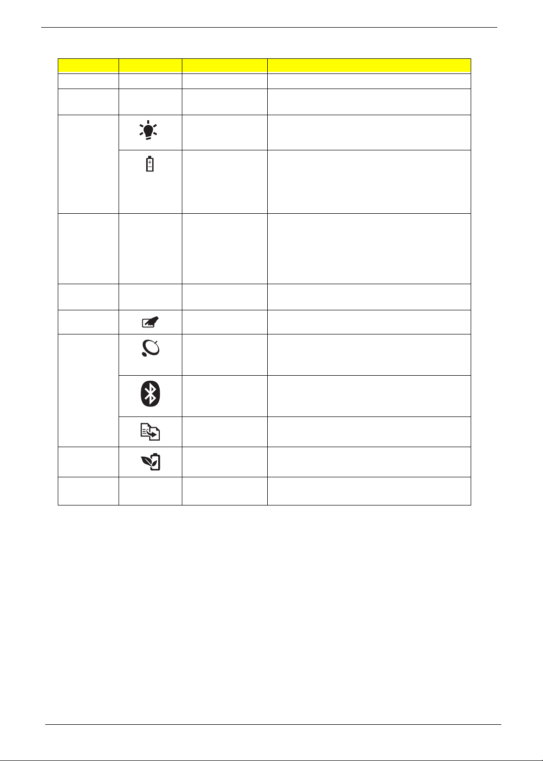
Hotkey Icon Function Description
<Fn> + <F2> System Properties Display the System Properties dialog box.
<Fn> + <F3> Bluetooth Enables/disables the Bluetooth
function. (only for certain models)
<Fn> + <F4> Sleep Puts the computer in Sleep mode.
<Fn> + <F5> Display toggle Switches display output between the display
screen, external monitor (if connected) and
both.
<Fn> + <F6> Screen blank Turns the display screen backlight off to save
power. Press any key to return.
<Fn> + <F8> Speaker toggle Turns the speakers on and off.
<Fn> + < > Brightness up Increases the screen brightness.
<Fn> + < > Brightness down Decreases the screen brightness.
<Fn> + < >
<Fn> + < >
Volume up Increases the sound volume.
Volume down Decreases the sound volume.
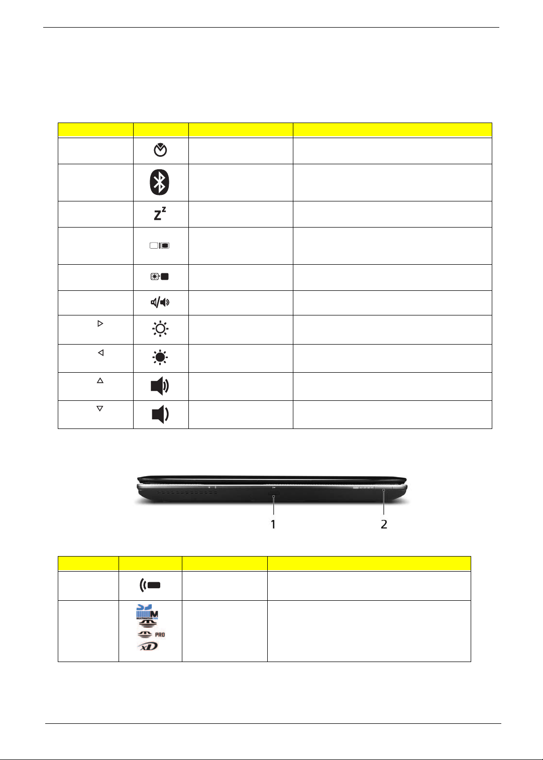
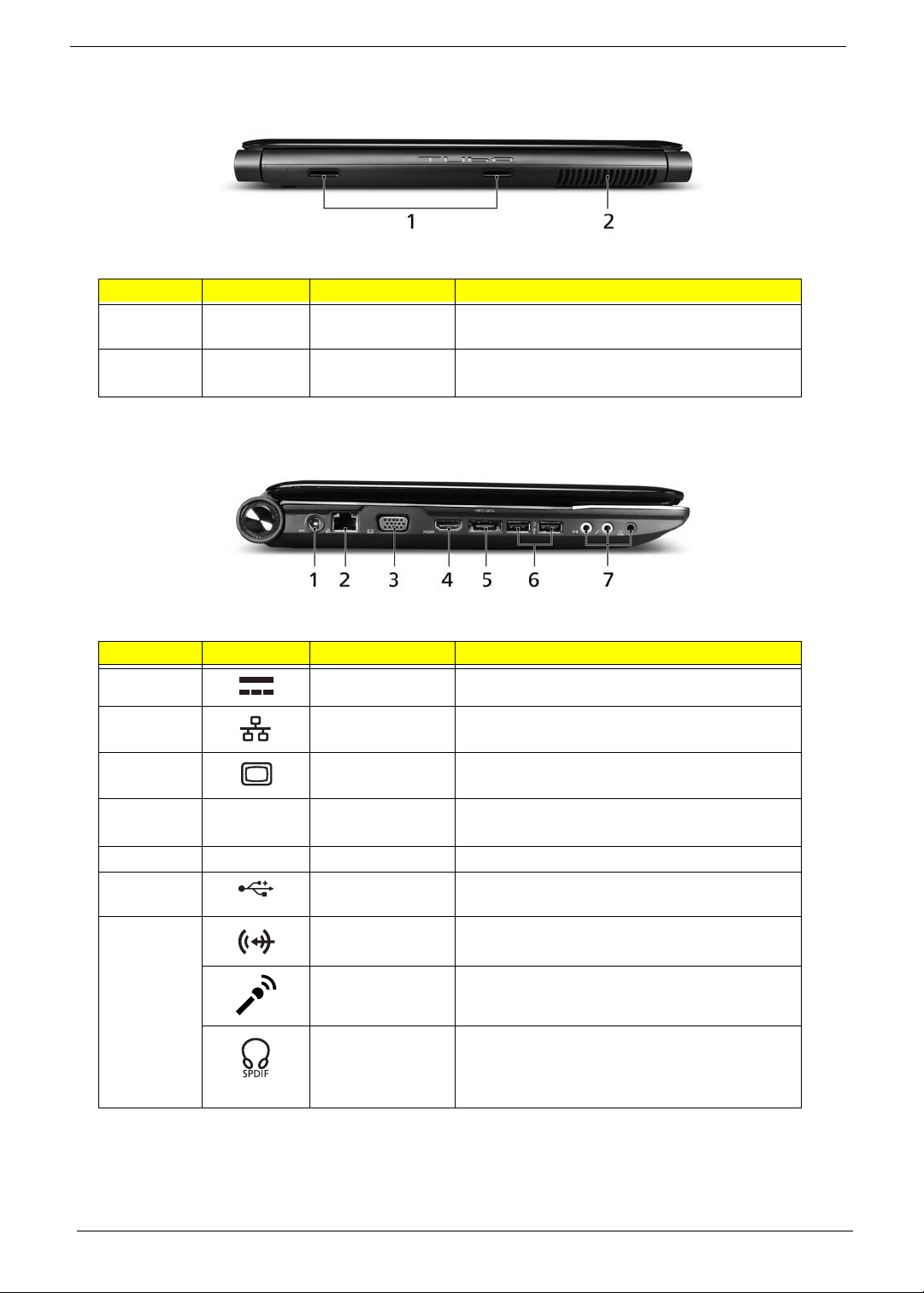
Closed Front View
No. Icon Item Description
1 CIR Receiver Receives signals from a remote
control.
2 5-in-1 card
reader
Accepts Secure Digital (SD), MultiMediaCard
(MMC), Memory Stick (MS), Memory Stick
PRO (MS PRO), xD-Picture Card (xD).
Note: Push to remove/install the card. Only
one card can operate at any given time.
Chapter 1 7
Rear View
No. Icon Item Description
1 Tuba The dedicated Tuba CineBass subwoofer
pumps out earthshaking movie-house audio.
2 Ventilation slots Allows the computer to stay cool, even after
prolonged use.
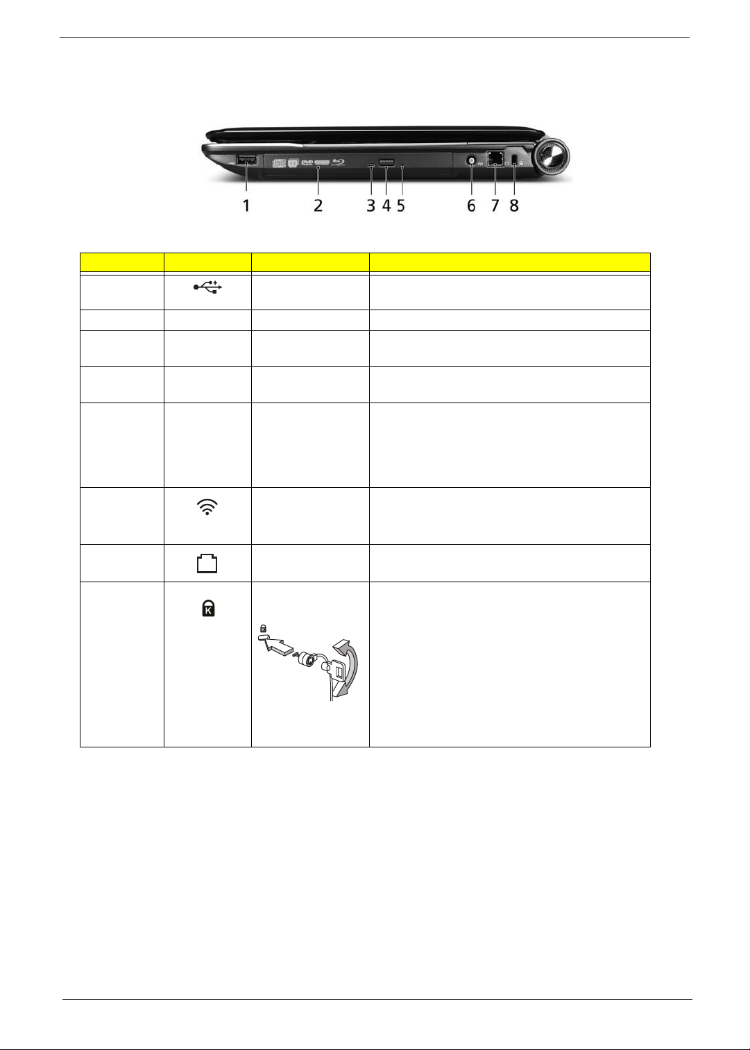
Left View
No. Icon Item Description
1 DC-In jack Connects to an AC adapter.
2 Ethernet (RJ-45)
port
3 External display
(VGA) port
HDMI HDMI port Supports high definition digital video
eSATA eSATA port Connects to eSATA devices.
4
5 Line-in jack Accepts audio line-in devices (e.g., audio CD
USB 2.0 port Connect to USB 2.0 devices (e.g. USB mouse,
Microphone jack Accepts inputs from external microphones.
Headphones/
speaker/line-out
jack with S/PDIF
support
Connects to an Ethernet 10/100/1000-based
network.
Connects to a display device
(e.g. external monitor, LCD projector).
connections.
USB camera)
player, stereo walkman, mp3 player)
Connects to audio line-out devices
(e.g., speakers, headphones).
8 Chapter 1
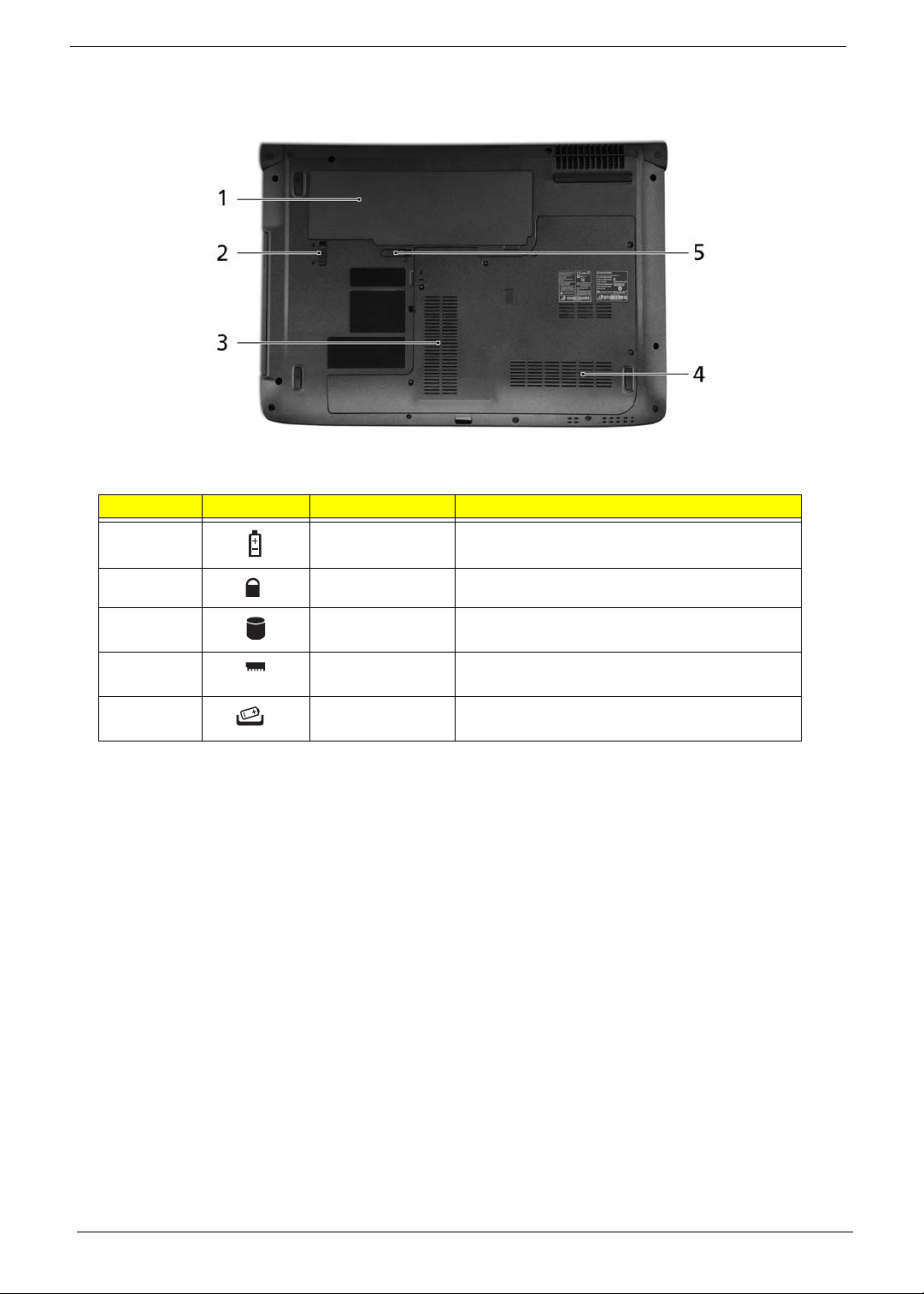
Right View
No. Icon Item Description
1 USB 2.0 port Connect to USB 2.0 devices (e.g. USB mouse,
USB camera).
2 Optical drive Internal optical drive; accepts CDs or DVDs.
3 Optical disk access
indicator
4 Optical drive eject
button
5 Emergency eject
hole
RF-in port Accepts input signals from digital TVtuner
Modem (RJ-11)
port
Kensington lock
slot
Lights up when the optical drive is active.
Ejects the optical disk from the drive.
Ejects the optical drive tray when the computer is
turned off.
Note: Insert a paper clip into the emergency eject
hole to eject the optical drive tray when the
computer is off.
devices.
(only for certain models)
Connects to a phone line.
Connects to a Kensington-compatible
computer security lock.
Note: Wrap the computer security
lock cable around an immovable
object such as a table or handle of a
locked drawer. Insert the lock into the
notch and turn the key to secure the
lock. Some keyless models are also
available.
Chapter 1 9
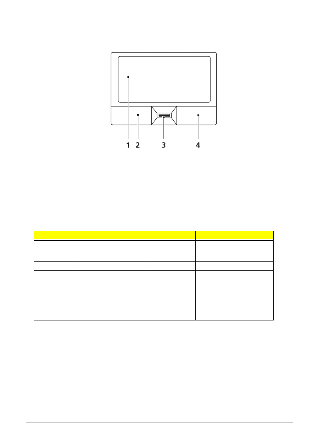
Bottom View
No. Icon Item Description
1 Battery bay Houses the computer's battery pack.
2 Battery lock Locks the battery in position.
3 Hard disk bay Houses the computer's hard disk (secured with
screws).
4 Memory
compartment
5 Battery release
latch
Houses the computer's main memory.
Releases the battery for removal.
10 Chapter 1
Touchpad Basics (with fingerprint reader)
The following items show you how to use the touchpad with Acer Bio-Protection fingerprint reader:
• Move your finger across the touchpad (1) to move the cursor.
• Press the left (2) and right (4) buttons located beneath the touchpad to perform selection and
execution functions. These two buttons are similar to the left and right buttons on a mouse.
Tapping on the touchpad is the same as clicking the left button.
• Use Acer Bio-Protection fingerprint reader (3) supporting Acer FingerNav 4-way control function
(only for certain models) or the 4-way scroll (3) button (only for certain models) to scroll up or down
and move left or right a page. This fingerprint reader or button mimics your cursor pressing on the
right scroll bar of Windows applications.
Function Left Button (2) Right Button (4) Main touc hpad (1)
Execute Quickly click twice. Tap twice (at the same speed
as double-clicking a mouse
button).
Select Click once. Tap once.
Drag Click and hold, then use
finger on the touchpad to
drag the cursor.
Tap twice (at the same speed
as double-clicking a mouse
button); rest your finger on
the touchpad on the second
tap and drag the cursor.
Access
Click once.
context menu
NOTE: When using the touchpad, keep it - and your fingers - dry and clean. The touchpad is sensitive to finger
movement; hence, the lighter the touch, the better the response. Tapping too hard will not increase the
touchpad’s responsiveness.
Chapter 1 11
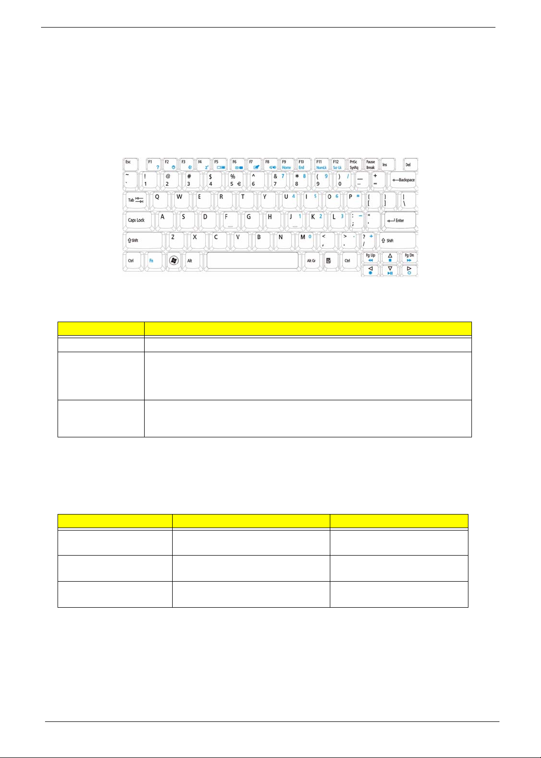
Using the Keyboard
The keyboard has full-sized keys and an embedded numeric keypad, separate cursor, lock, Windows, function
and special keys.
Lock Keys and embedded numeric keypad
The keyboard has three lock keys which you can toggle on and off.
Lock key Description
Caps Lock When Caps Lock is on, all alphabetic characters typed are in uppercase.
Num Lock
<Fn> + <F11>
Scroll Lock <Fn> +
<F12>
When Num Lock is on, the embedded keypad is in numeric mode. The keys
function as a calculator (complete with the arithmetic operators +, -, *, and /). Use
this mode when you need to do a lot of numeric data entry. A better solution
would be to connect an external keypad.
When Scroll Lock is on, the screen moves one line up or down when you press
the up or down arrow keys respectively. Scroll Lock does not work with some
applications.
The embedded numeric keypad functions like a desktop numeric keypad. It is indicated by small characters
located on the upper right corner of the keycaps. To simplify the keyboard legend, cursor-control key symbols
are not printed on the keys.
Desired access Num Lock on Num Lock off
Number keys on
embedded keypad
Cursor-control keys on
embedded keypad
Main keyboard keys Hold <Fn> while typing letters on
12 Chapter 1
Type numbers in a normal manner.
Hold <Shift> while using cursorcontrol keys.
embedded keypad.
Hold <Fn> while using cursorcontrol keys.
Type the letters in a normal
manner.
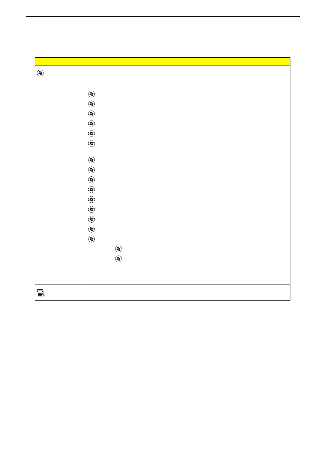
Windows Keys
The keyboard has two keys that perform Windows-specific functions.
Key Description
Windows key Pressed alone, this key has the same effect as clicking on the Windows Start button;
it launches the Start menu. It can also be used with other keys to provide a variety of
functions:
<>: Open or close the Start menu
<> + <D>: Display the desktop
<> + <E>: Open Windows Explore
<> + <F>: Search for a file or folder
<> + <G>: Cycle through Sidebar gadgets
<> + <L>: Lock your computer (if you are connected to a network domain), or
switch users (if you're not connected to a network domain)
<> + <M>: Minimizes all windows
<> + <R>: Open the Run dialog box
<> + <T>: Cycle through programs on the taskbar
<> + <U>: Open Ease of Access Center
<> + <X>: Open Windows Mobility Center
<> + <BREAK>: Display the System Properties dialog box
<> + <SHIFT+M>: Restore minimized windows to the desktop
<> + <TAB>: Cycle through programs on the taskbar by using Windows Flip 3-D
<> + <SPACEBAR>: Bring all gadgets to the front and select Windows Sidebar
Application
key
<CTRL> +
<CTRL> + <> + <TAB>: Use the arrow keys to cycle through programs on the
Note: Depending on your edition of Windows Vista, some shortcuts may not function
This key has the same effect as clicking the right mouse button; it opens the
application's context menu.
<> + <F>: Search for computers (if you are on a network)
taskbar by using Windows Flip 3-D
as described.
Chapter 1 13
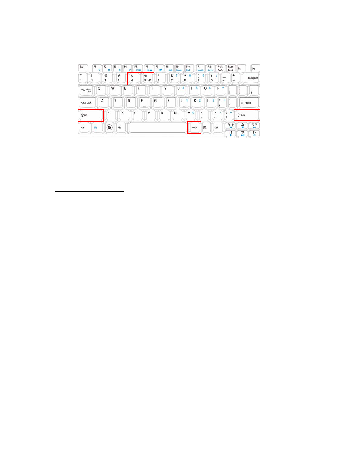
Special Key
You can locate the Euro symbol and the US dollar sign at the upper-center and/or bottom-right of your
keyboard.
The Euro symbol
1. Open a text editor or word processor.
2. Hold <Alt Gr> and then press the <5> key at the upper-center of the keyboard.
NOTE: Note: Some fonts and software do not support the Euro symbol. Please refer to www.microsoft.com/
typography/faq/faq12.htm for more information.
The US dollar sign
1. Open a text editor or word processor.
2. Hold <Shift> and then press the <4> key at the upper-center of the keyboard.
NOTE: This function varies by the operating system version.
14 Chapter 1
Using the System Utilities
Acer Bio-Protection (only for certain models) Acer Bio-Protection Fingerprint Solution is a multi-purpose
fingerprint software package integrated with the Microsoft Windows operating system. Utilizing the uniqueness
of one's fingerprint features, Acer Bio-Protection Fingerprint Solution has incorporated protection against
unauthorized access to your computer with centralized password management with Password Bank, easy
music player launching with Acer MusicLaunch, secure Internet favorites via Acer MyLaunch, and fast
application/website launching and login with Acer FingerLaunch, while Acer ProfileLaunch can launch up to
three applications/websites from a single finger swipe.
Acer Bio-Protection Fingerprint Solution also allows you to navigate through web browsers and documents
using Acer FingerNav. With Acer Bio-Protection Fingerprint Solution, you can now enjoy an extra layer of
protection for your personal computer, as well as the convenience of accessing your daily tasks with a simple
swipe of your finger!
For more information refer to the Acer Bio-Protection help files.
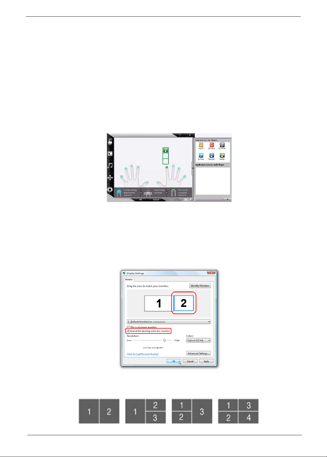
Acer GridVista (dual-display compatible)
NOTE: This feature is only available on certain models.
To enable the dual monitor feature of the notebook, first ensure that the second monitor is connected, then
select Start, Control Panel, Display and click on Settings. Select the secondary monitor (2) icon in the
display box and then click the check box Extend my windows desktop onto this monitor. Finally, click
Apply to confirm the new settings and click OK to complete the process.
Acer GridVista is a handy utility that offers four pre-defined display settings so you can view multiple windows
on the same screen. To access this function, please go to Start´ All Programs and click on Acer GridVista.
You may choose any one of the four display settings indicated below:
Chapter 1 15
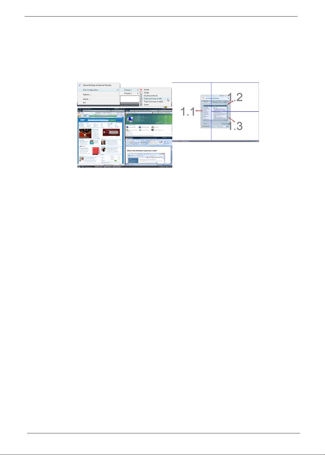
Double (vertical), Triple (primary at left), Triple (primary at right), or Quad Acer Gridvista is dual-display
compatible, allowing two displays to be partitioned independently.
Acer Gridvista is dual-display compatible, allowing two displays to be partitioned independently.
AcerGridVista is simple to set up:
1. Run Acer GridVista and select your preferred screen configuration for each display from the task bar.
2. Drag and drop each window into the appropriate grid.
3. Enjoy the convenience of a well-organized desktop.
NOTE: Please ensure that the resolution setting of the second monitor is set to the manufacturer's
recommended value.
16 Chapter 1
Hardware Specifications and Configurations
Processor
Item Specification
CPU Type INTEL Penryn processor on 45-nanometer process technology
Core Logic
CPU Package 479-ball Micro-FCBGA
• Dual-core processor for mobile with enhanced performance
• Supports Intel® architecture with IntelR Wide Dynamic Execution
• Supports L1 cache-to-cache (C2C) transfer
• On-die, primary 32-kB instruction cache and 32-kB write-back data cache in
each core
• The Penryn processor in XE, SV and LV have an On-die, up to 6-MB second-
level shared cache with Advanced Transfer Cache architecture
• The Penryn processor in ULV have an On-die, up to 3-MB second-levelshared
cache with Advanced Transfer Cache architecture
• Streaming SIMD extensions 2 (SSE2), streaming SIMD extensions 3(SSE3),
supplemental streaming SIMD extensions 3 (SSSE3) and SSE4.1instruction sets
• The Penryn processor in XE, SV and LV are offered at 667-MHz, 800-MHz and
1066-MHz source-synchronous front side bus (FSB)
• The Penryn processor in ULV are offered at 667-MHz and 800-MHz source
synchronous front side bus (FSB)
• Advanced power management features including Enhanced Intel SpeedStep®
Technology and dynamic FSB frequency switching
• Digital thermal sensor (DTS)
• IntelR 64 architecture
• Supports enhanced Intel® Virtualization Technology
• Intel® Dynamic Acceleration Technology and Enhanced Multi Threaded¡
Supports PSI2 functionality
• The Penryn processor in XE, SV are offered in Micro-FCPGA and Micro-FCBGA
packaging technologies
• The Penryn SFF processor in LV and ULV are offered in Micro-FCBGA
packaging technologies only
• Execute Disable Bit support for enhanced security
• C6 Low Power Feature with P_LVL6 I/O Support
• Support for Intel® Trusted Execution Technology
• Half ratio support (N/2) for Core to Bus ratio
Processor Specifications
Processor
#
P7450 2.4G
P8600 2.4G
P8600 2.4G
P8700 2.53G
P9500 2.53G
T6400 2.0G
T6600 2.2G
CPU
Speed
Cores
2
2
2
2
2
2
2
Bus
Speed
1066
1066
1066
1066
1066
800
800
Mfg
Tech
45 nm
45 nm
45 nm
45 nm
45 nm
45 nm
45 nm
Cache
Size
Package Power Acer P/N
3M FCBGA
3M FCBGA
3M FCBGA
3M FCBGA
6M FCBGA
3M FCBGA
2M FCBGA
Chapter 1 17
Processor
#
T9550 2.66G
T9600 2.8G
T9800 2.93G
CPU
Speed
Cores
2
2
2
Bus
Speed
1066
1066
1066
Mfg
Tech
45 nm
45 nm
45 nm
Cache
Size
6M FCBGA
6M FCBGA
6M FCBGA
System Board North / South Bridge
Item Specifications
Core logic
• Intel® ICH9M I/O controller.
• Intel CS GM45NB / Intel CS PM45NB (North Bridge)
CPU Fan True Value Table
CPU Temperature (°C) Fan Speed (rpm) SPL Spec (dBA)
40 2800 28
50 3100 31
65 3400 34
85 4000 37
105 4500 40
• Throttling 50%: On =105°C; Off=95°C
• OS Shut down: 108°C
• H/W Shut down: 110°C
BIOS ROM
Package Power Acer P/N
Item Specification
BIOS Vendor Phoenix BIOS
BIOS Version V0.3209
BIOS ROM Type Flash ROM
BIOS ROM Size 2MB
Supported Protocols SMBIOS 2.3
BIOS Password control Yes
Features
• Support Acer UI
• Support multi-boot
• Suspend to RAM (S3)/Disk (S4)
• Va rious hot-key s for system control
• Support SMBIOS 2.3, PCI2.2
• DMI utility for BIOS serial number configurable/asset tag
• Support PXE
• Support Win Flash
• Wake on LAN from S3
• Wake on LAN form S5 in AC mode
• System information
18 Chapter 1
System Memory
Item Specifications
Memory Controller Built-in
Memory Size 0MB (no on-board memory)
DIMM socket number 2
Supports Memory size
per socket
Support maximum
memory size
Support DIMM type DDR II SDRAM
Support DIMM Speed 667/800MHz
Support DIMM voltage +1.8V
Support DIMM
package
VGA Memory 64/128/256MB
Memory module
combinations
Memory Combinations
2GB
4GB
200-pin
You can install memory modules in any combinations as long as they match
the above specifications.
Slot 1 Slot 2 Total Memory
0MB 512MB 512MB
0MB 1024MB 1024MB
0MB 2048MB 2048MB
512MB 512MB 1024MB
512MB 1024MB 1536MB
512MB 2048MB 2560MB
1024MB 0MB 1024MB
1024MB 512MB 1536MB
1024MB 1024MB 2048MB
1024MB 2048MB 3072MB
2048MB 0MB 2048MB
2048MB 512MB 2560MB
2048MB 1024MB 3072MB
2048MB 2048MB 4096MB
NOTE: Above table lists some system memory configurations. You may combine DIMMs with various
capacities to form other combinations. On above table, the configuration of slot 1 and slot 2 could be
reversed.
Chapter 1 19
Hard Disk Drive Interface
Item Specifications
Vendor & Model
Name
Capacity (MB)
Hitachi
HTS545050B9A300
500 320 250 160
Hitachi
HTS545032B9A300
Bytes per sector
Data heads
4322
Drive Format
Disks
2211
Spindle speed
(RPM)
Performance Specifications
Buffer size
Interface
Internal transfer
rate (Mbits/sec,
max)
I/O data transfer
875 Mbits/s maximum 845 Mbits/s
rate
(Mbytes/sec
max)
DC Power Requirements
Voltage
Hitachi
HTS545025B9A300
512
5400
8MB
SATA
3GB/s maximum
+5.0V ± 5%.
Hitachi
HTS545016B9A300
maximum
Item Specifications
Vendor & Model
Name
Capacity (MB)
Bytes per sector
Data heads
Seagate
ST9160310AS
160 250 320 500
512 512 512 512
2244
Seagate
ST9250315AS
Drive Format
Disks
Spindle speed
1122
5400 5400 5400 5400
(RPM)
Performance Specifications
Buffer size
Interface
Internal transfer
8 MB 8 MB 8MB 8 MB
SATA SATA SATA SATA
830
1175 830 1175
rate (Mbits/sec,
max)
I/O data transfer
875 Mbits/s maximum 845 Mbits/s
rate
(Mbytes/sec
max)
DC Power Requirements
Voltage
Seagate
ST9320320AS
+5.0V ± 5%.
Seagate
ST9500325AS
maximum
20 Chapter 1
 Loading...