

Page 1

Aspire 1410/1680 Series
Service Guide
Page 2
Revision History
Please refer to the table below for the updates made on Aspire 1410/1680 service guide.
Date Chapter Updates
II
Page 3

Copyright
Copyright © 2004 by Acer Incorporated. All rights reserved. No part of this publication may be reproduced,
transmitted, transcribed, stored in a retrieval system, or translated into any language or computer language, in
any form or by any means, electronic, mechanical, magnetic, optical, chemical, manual or otherwise, without
the prior written permission of Acer Incorporated.
Disclaimer
The information in this guide is subject to change without notice.
Acer Incorporated makes no representations or warranties, either expressed or implied, with respect to the
contents hereof and specifically disclaims any warranties of merchantability or fitness for any particular
purpose. Any Acer Incorporated software described in this manual is sold or licensed "as is". Should the
programs prove defective following their purchase, the buyer (and not Acer Incorporated, its distributor, or its
dealer) assumes the entire cost of all necessary servicing, repair, and any incidental or consequential
damages resulting from any defect in the software.
Intel is a registered trademark of Intel Corporation.
Pentium and Pentium II/III are trademarks of Intel Corporation.
Other brand and product names are trademarks and/or registered trademarks of their respective holders.
III
Page 4
Conventions
The following conventions are used in this manual:
Screen messages Denotes actual messages that appear
on screen.
NOTE Gives bits and pieces of additional
information related to the current
topic.
WARNING Alerts you to any damage that might
result from doing or not doing specific
actions.
CAUTION Gives precautionary measures to
avoid possible hardware or software
problems.
IMPORTANT Reminds you to do specific actions
relevant to the accomplishment of
procedures.
IV
Page 5

Preface
Before using this information and the product it supports, please read the following general information.
1. This Service Guide provides you with all technical information relating to the BASIC CONFIGURATION
decided for Acer "global" product offering. To better fit local market requirements and enhance product
competitiveness, your regional office MAY have decided to extend the functionality of a machine (e.g.
add-on card, modem, or extra memory capability). These LOCALIZED FEATURES will NOT be covered
in this generic service guide. In such cases, please contact your regional offices or the responsible
personnel/channel to provide you with further technical details.
2. Please note WHEN ORDERING FRU PARTS, that you should check the most up-to-date information
available on your regional web or channel. If, for whatever reason, a part number change is made, it will
not be noted in the printed Service Guide. For ACER AUTHORIZED SERVICE PROVIDERS, your Acer
office may have a DIFFERENT part number code to those given in the FRU list of this printed Service
Guide. You MUST use the list provided by your regional Acer office to order FRU parts for repair and
service of customer machines.
V
Page 6

VI
Page 7
V.7 5/312004
e
4
A
4
A
4
A
A
A
4
A
A
0
A
0
0
V
V
4
V
5
V
4
V
6
V
5
V
4
-
A
)
)
)
)
)
)
/
r
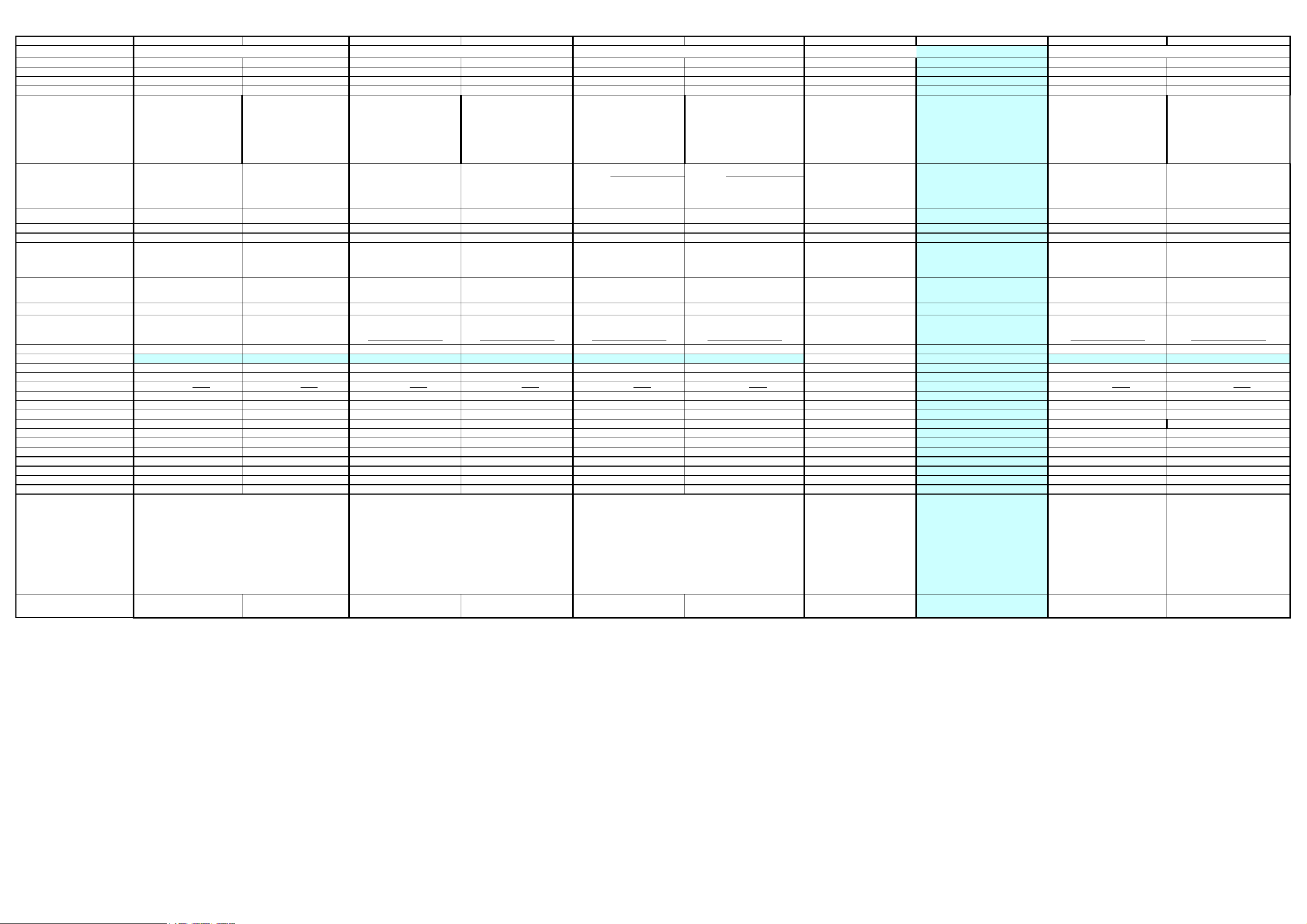
Shipping priority No. 5 No. 6 No. 4 No. 3 No. 1 on Jul.20th No. 2 End of August
Quanta Named ZL1E ???
Project Nam
Platform naming TM4500 TM4500 TM4000 TM4000
M/B VERSION A1 VERSION A2
Chipset 855GME 855GME 855GME 855GME 855GME 855GME 852GM 855GME 855GME 855GME
Kestrel-P-M11P6
ZL1 ZL1A ZL1C
Kestrel-P-UM
Kestrel / Extensa /ZL1 Series Model Comparision Table
Kestrel-M11P6
ERSION A3
Kestrel-UM
ERSION A
Kestrel-A-M11P6
S168
ERSION A
Kestrel-A-UM
S168
ERSION A
Kestrel-E-UM
TM2300 AS141
ERSION A
Kestrel-A-UM
???
Kestrel-A-M11P6
ZL1G
Extensa3000 Extensa3000
ERSION A
Kestrel-A-UM
ERSION A
Banias 1.5
Dothan 1.5G
Dothan 1.6G
Dothan 1.7G
CPU
15" XGA
LCD
VGA
Console display NO NO NO NO NO NO NO NO NO NO
Arcade windows mode NO NO NO NO YES YES NO YES NO NO
Optical
Hot swapple
HDD
wireless
WNC Bluetooth YES YES NO NO YES YES NO YES NO NO
Battery Life 5hrs(8 cells) 5hrs(8 cells) 2.5hrs(4-cells)/5hrs(8 cells
Battery cell 8 cells 8 cells 8 cells 8 cells 8 cells 8 cells 4 cells 8cells 8 cells 8 cells
Port replicator EasyPort 3 EasyPort 3 NO NO NO NO NO NO NO NO
LAN 10/100
Card reade
Smart card NO NO NO NO NO NO NO NO NO NO
DASP NO NO NO NO NO NO NO NO NO NO
Keyboard New Ergo New Ergo New Ergo New Ergo normal normal New Ergo normal normal normal
Subwoofer NO NO NO NO NO NO NO NO NO NO
SPDIF NO NO NO NO NO NO NO NO NO NO
OS XPPRO & XPHOME with SP2 XPPRO & XPHOME with SP2 XPPRO & XPHOME with SP2 XPPRO & XPHOME with SP2 XPPRO & XPHOME with SP2 XPPRO & XPHOME with SP2 XPPRO & XPHOME with SP2 XPPRO & XPHOME with SP2 XPPRO & XPHOME with SP2 XPPRO & XPHOME with SP2
Driver support W2K & NT limit support W2K & NT limit support W2K limit support W2K limit support NO NO W2K limit support NO NO NO
Disk to Disk YES YES YES YES YES YES YES YES YES YES
NB manager 2 YES YES YES YES NO NO YES NO NO NO
weight 2.86kgs 2.86kgs 2.86kgs 2.86kgs 2.86kgs 2.86kgs 2.86kgs 2.86kgs 2.86kgs 2.86kgs
15" SXGA+
15.4" WXGA
ATI 9700 with 64MB UMA ATI 9700 with 64MB UMA ATI 9700 with 64MB UMA UMA UMA ATI 9700 with 64MB UMA
Combo
DVD-SuperMulti
DVD-Dual
2nd HDD, 2nd battery,
weight saver
40GB / 60GB / 80GB 40GB / 60GB / 80GB 30/40/60/80GB 30/40/60/80GB 30/40/60/80GB 30/40/60/80GB 30/40/60/80GB 30/40/60/80GB 30/40/60/80GB 30/40/60/80GB
Intel 802.11b/g
Intel 802.11a/b/g
1000 10/100/1000 10/100/1000 10/100/1000 10/100/1000 10/100/1000 10/100 10/100 10/100/1000 10/100/1000
MMC/MS/SD MMC/MS/SD NO NO MMC/MS/SD NO NO NO MMC/MS/SD NO
Banias 1.5
Dothan 1.5G
Dothan 1.6G
Dothan 1.7G
15" XGA
15" SXGA+
15.4" WXGA
Combo
DVD-SuperMulti
DVD-Dual
2nd HDD, 2nd battery,
weight saver
Intel 802.11b/g
Intel 802.11a/b/g
Banias 1.5
Dothan 1.5G
Dothan 1.6G
14.1" XGA
15" XGA
15.4" WXGA
Combo
DVD-Dual
DVD-SuperMulti
NO NO NO NO NO NO NO NO
Intel 802.11b/g
3rd party 802.11a/b/g
Banias 1.5
Dothan 1.5G
Dothan 1.6G
14.1" XGA
15" XGA
15.4" WXGA
Combo
DVD-Dual
DVD-SuperMulti
Intel 802.11b/g
3rd party 802.11a/b/g
2.5hrs(4-cells)/5hrs(8 cells)2.5hrs(4-cells)/5hrs(8 cells
Banias 1.5
Dothan 1.5G
Dothan 1.6G
14.1" XGA
15.4" WXGA
15" XGA
Combo
DVD-SuperMulti
DVD-Dual
Intel 802.11b/g
3rd party 802.11a/b/g
Banias 1.5
Dothan 1.5G
Dothan 1.6G
14.1" XGA
15.4" WXGA
15" XGA
Combo
DVD-SuperMulti
DVD-Dual
Intel 802.11b/g
3rd party 802.11a/b/g
2.5hrs(4-cells)/5hrs(8 cells
Celeron M 320
Celeron M 330
Celeron M 340
Celeron M 350
Celeron M 360
14.1" XGA
15" XGA
15.4" WXGA
Combo
DVD-Dual
DVD-SuperMulti
mbit 802.11b/g
2hrs(4-cells) 2hrs(4-cells)/5hrs(8 cells
Combo DVD
Celeron M 320
Celeron M 330
Celeron M 340
14.1" XGA
15" XGA
15.4" WXGA
SuperMulti DVD-
Dual
Foxconn 802.11b/g(first priority)
Intel 802.11b/g
Dothan 1.5G Dothan 1.5G
15" XGA 15.4"
WXGA 15"
SXGA+(tender)
Combo
4X DVD-Dual
Intel 802.11b/g
3rd party 802.11a/b/g
2.5hrs(4-cells)/5hrs(8 cells
15" XGA 15.4"
WXGA 15"
SXGA+(tender)
Combo
4X DVD-Dual
Intel 802.11b/g
3rd party 802.11a/b/g
2.5hrs(4-cells)/5hrs(8 cells
IO Port
dimension
Three USB 2.0 ports/ IEEE 1394 port/ Ethernet (RJ-45) port/
Modem (RJ-11) port/ External display (VGA) port/ S-
Video/TV-out port/ Microphone/line-in jack
/Headphones/speaker/line-out port /Infrared (FIR) port/ PC
Card slot (one Type II)/ 3-in-1 card reader (MS/MMC/SD)/
100-pin port replicator connector/ DC-in jack for AC
adaptor
360 (W) x 273 (D) x 27/32 (H) mm360 (W) x 273 (D) x 27/32 (H)
mm
Three USB 2.0 ports/ IEEE 1394 port/ Ethernet (RJ-45)
port/ Modem (RJ-11) port/ External display (VGA) port/ S-
video/TV-out port/ Microphone/line-in jack/
Headphones/speaker/line-out port/ Infrared (FIR) port/ PC
Card slot (one Type II)/ DC-in jack for AC adaptor
360 (W) x 273 (D) x 27/32 (H) mm360 (W) x 273 (D) x 27/32 (H) mm360 (W) x 273 (D) x 27/32 (H) mm360 (W) x 273 (D) x 27/32 (H) mm360 (W) x 273 (D) x 27/32 (H)
Three USB 2.0 ports/ IEEE 1394 port/ Ethernet (RJ-45) port/
Modem (RJ-11) port/ S-video/TV-out port (NTSC/PAL)/ External
display (VGA) port/ Microphone/line-in jack/
Headphones/speaker/line-out port/ Infrared (FIR) port/ PC Card
slot (one Type II)/ DC-in jack for AC adaptor
mm 360 (W) x 273 (D) x 27/32 (H) mm
360 (W) x 273 (D) x 27/32 (H)
mm 360 (W) x 273 (D) x 27/32 (H) mm
Page 8

Table of Contents
Chapter 1 System Introduction 1
Features . . . . . . . . . . . . . . . . . . . . . . . . . . . . . . . . . . . . . . . . . . . . . . . . . . . . . . . . . . . .1
System Block Diagram . . . . . . . . . . . . . . . . . . . . . . . . . . . . . . . . . . . . . . . . . . . . . . . . .3
Board Layout . . . . . . . . . . . . . . . . . . . . . . . . . . . . . . . . . . . . . . . . . . . . . . . . . . . . . . . .4
Top View . . . . . . . . . . . . . . . . . . . . . . . . . . . . . . . . . . . . . . . . . . . . . . . . . . . . . . . .4
Bottom View . . . . . . . . . . . . . . . . . . . . . . . . . . . . . . . . . . . . . . . . . . . . . . . . . . . . .5
An Aspire Tour . . . . . . . . . . . . . . . . . . . . . . . . . . . . . . . . . . . . . . . . . . . . . . . . . . . . . . .7
Front View . . . . . . . . . . . . . . . . . . . . . . . . . . . . . . . . . . . . . . . . . . . . . . . . . . . . . . .7
Closed Front View . . . . . . . . . . . . . . . . . . . . . . . . . . . . . . . . . . . . . . . . . . . . . . . . .8
Left View . . . . . . . . . . . . . . . . . . . . . . . . . . . . . . . . . . . . . . . . . . . . . . . . . . . . . . . .9
Right View . . . . . . . . . . . . . . . . . . . . . . . . . . . . . . . . . . . . . . . . . . . . . . . . . . . . . .10
Rear Panel . . . . . . . . . . . . . . . . . . . . . . . . . . . . . . . . . . . . . . . . . . . . . . . . . . . . .11
Bottom Panel . . . . . . . . . . . . . . . . . . . . . . . . . . . . . . . . . . . . . . . . . . . . . . . . . . .12
Indicators . . . . . . . . . . . . . . . . . . . . . . . . . . . . . . . . . . . . . . . . . . . . . . . . . . . . . .13
Using the Keyboard . . . . . . . . . . . . . . . . . . . . . . . . . . . . . . . . . . . . . . . . . . . . . . . . . .15
Lock Keys . . . . . . . . . . . . . . . . . . . . . . . . . . . . . . . . . . . . . . . . . . . . . . . . . . . . . .15
Embedded Numeric Keypad . . . . . . . . . . . . . . . . . . . . . . . . . . . . . . . . . . . . . . . .16
Windows Keys . . . . . . . . . . . . . . . . . . . . . . . . . . . . . . . . . . . . . . . . . . . . . . . . . .17
Hot Keys . . . . . . . . . . . . . . . . . . . . . . . . . . . . . . . . . . . . . . . . . . . . . . . . . . . . . . .18
Special Key . . . . . . . . . . . . . . . . . . . . . . . . . . . . . . . . . . . . . . . . . . . . . . . . . . . . .20
Launch Keys . . . . . . . . . . . . . . . . . . . . . . . . . . . . . . . . . . . . . . . . . . . . . . . . . . . .21
Touchpad . . . . . . . . . . . . . . . . . . . . . . . . . . . . . . . . . . . . . . . . . . . . . . . . . . . . . .23
Touchpad Basics . . . . . . . . . . . . . . . . . . . . . . . . . . . . . . . . . . . . . . . . . . . . . . . .23
Hardware Specifications and Configurations . . . . . . . . . . . . . . . . . . . . . . . . . . . . . . .25
Chapter 2 System Utilities 36
BIOS Setup Utility . . . . . . . . . . . . . . . . . . . . . . . . . . . . . . . . . . . . . . . . . . . . . . . . . . . .36
Navigating the BIOS Utility . . . . . . . . . . . . . . . . . . . . . . . . . . . . . . . . . . . . . . . . .37
Information . . . . . . . . . . . . . . . . . . . . . . . . . . . . . . . . . . . . . . . . . . . . . . . . . . . . .38
Main . . . . . . . . . . . . . . . . . . . . . . . . . . . . . . . . . . . . . . . . . . . . . . . . . . . . . . . . . .39
Advanced . . . . . . . . . . . . . . . . . . . . . . . . . . . . . . . . . . . . . . . . . . . . . . . . . . . . . .41
Security . . . . . . . . . . . . . . . . . . . . . . . . . . . . . . . . . . . . . . . . . . . . . . . . . . . . . . . .43
Boot . . . . . . . . . . . . . . . . . . . . . . . . . . . . . . . . . . . . . . . . . . . . . . . . . . . . . . . . . . .47
Exit . . . . . . . . . . . . . . . . . . . . . . . . . . . . . . . . . . . . . . . . . . . . . . . . . . . . . . . . . . .48
BIOS Flash Utility . . . . . . . . . . . . . . . . . . . . . . . . . . . . . . . . . . . . . . . . . . . . . . . . . . . .49
Chapter 3 Machine Disassembly and Replacement 50
General Information . . . . . . . . . . . . . . . . . . . . . . . . . . . . . . . . . . . . . . . . . . . . . . . . . .51
Before You Begin . . . . . . . . . . . . . . . . . . . . . . . . . . . . . . . . . . . . . . . . . . . . . . . .51
Disassembly Procedure Flowchart . . . . . . . . . . . . . . . . . . . . . . . . . . . . . . . . . . . . . . .53
Removing the Battery Pack . . . . . . . . . . . . . . . . . . . . . . . . . . . . . . . . . . . . . . . . . . . .55
Removing the HDD Module/the Memory and the Wireless LAN Card/the Thermal Module
and the CPU/ODD Module and LCD Module . . . . . . . . . . . . . . . . . . . . . . . . . . . . . . .56
Removing the HDD Module . . . . . . . . . . . . . . . . . . . . . . . . . . . . . . . . . . . . . . . .56
Removing the Memory and the Wireless LAN Card . . . . . . . . . . . . . . . . . . . . . .56
Removing the Thermal Module and CPU . . . . . . . . . . . . . . . . . . . . . . . . . . . . . .56
Removing the ODD Module . . . . . . . . . . . . . . . . . . . . . . . . . . . . . . . . . . . . . . . .58
Removing the LCD Module . . . . . . . . . . . . . . . . . . . . . . . . . . . . . . . . . . . . . . . . .58
Disassembling the Main Unit . . . . . . . . . . . . . . . . . . . . . . . . . . . . . . . . . . . . . . . . . . .60
Separate the Main Unit Into the Upper and the Lower Case Assembly . . . . . . .60
Disassembling the Upper Case Assembly . . . . . . . . . . . . . . . . . . . . . . . . . . . . .60
Disassembling the Lower Case Assembly . . . . . . . . . . . . . . . . . . . . . . . . . . . . .61
VII
Page 9

Table of Contents
Disassembling the LCD Module . . . . . . . . . . . . . . . . . . . . . . . . . . . . . . . . . . . . . . . . .64
Disassembling the External Modules . . . . . . . . . . . . . . . . . . . . . . . . . . . . . . . . . . . . .66
Disassembling the Optical Drive Module . . . . . . . . . . . . . . . . . . . . . . . . . . . . . .66
Chapter 4 Troubleshooting 68
System Check Procedures . . . . . . . . . . . . . . . . . . . . . . . . . . . . . . . . . . . . . . . . . . . . .69
External Diskette Drive Check . . . . . . . . . . . . . . . . . . . . . . . . . . . . . . . . . . . . . .69
External CD-ROM Drive Check . . . . . . . . . . . . . . . . . . . . . . . . . . . . . . . . . . . . .69
Keyboard or Auxiliary Input Device Check . . . . . . . . . . . . . . . . . . . . . . . . . . . . .69
Memory check . . . . . . . . . . . . . . . . . . . . . . . . . . . . . . . . . . . . . . . . . . . . . . . . . . .70
Power System Check . . . . . . . . . . . . . . . . . . . . . . . . . . . . . . . . . . . . . . . . . . . . .70
Touchpad Check . . . . . . . . . . . . . . . . . . . . . . . . . . . . . . . . . . . . . . . . . . . . . . . . .72
Power-On Self-Test (POST) Error Message . . . . . . . . . . . . . . . . . . . . . . . . . . . . . . .73
Index of Error Messages . . . . . . . . . . . . . . . . . . . . . . . . . . . . . . . . . . . . . . . . . . . . . . .74
POST Code . . . . . . . . . . . . . . . . . . . . . . . . . . . . . . . . . . . . . . . . . . . . . . . . . . . . . . . .77
Index of Symptom-to-FRU Error Message . . . . . . . . . . . . . . . . . . . . . . . . . . . . . . . . .78
Intermittent Problems . . . . . . . . . . . . . . . . . . . . . . . . . . . . . . . . . . . . . . . . . . . . . . . . .81
Undetermined Problems . . . . . . . . . . . . . . . . . . . . . . . . . . . . . . . . . . . . . . . . . . . . . . .82
Use NAPP CD to Build Master Hard Disc Drive . . . . . . . . . . . . . . . . . . . . . . . . . . . . .83
CD to Disk Recovery . . . . . . . . . . . . . . . . . . . . . . . . . . . . . . . . . . . . . . . . . . . . . .83
Disk to Disk Recovery . . . . . . . . . . . . . . . . . . . . . . . . . . . . . . . . . . . . . . . . . . . . .86
Chapter 5 Jumper and Connector Locations 90
Top View . . . . . . . . . . . . . . . . . . . . . . . . . . . . . . . . . . . . . . . . . . . . . . . . . . . . . . .90
Bottom View . . . . . . . . . . . . . . . . . . . . . . . . . . . . . . . . . . . . . . . . . . . . . . . . . . . .92
Chapter 6 FRU (Field Replaceable Unit) List 94
Exploded Diagram . . . . . . . . . . . . . . . . . . . . . . . . . . . . . . . . . . . . . . . . . . . . . . . . . . .95
Appendix A Model Definition and Configuration 108
Model Name Definition . . . . . . . . . . . . . . . . . . . . . . . . . . . . . . . . . . . . . . . . . . . . . . .108
Appendix B Test Compatible Components 110
Microsoft Windows XP Environment Test . . . . . . . . . . . . . . . . . . . . . . . . . . . . . . . . .111
Appendix C Online Support Information 116
Index 118
VIII
Page 10

IX
Page 11

System Introduction
Features
Below is a brief summary of the computer’s many feature:
Performance
T Intel
T Intel
T 256/512 MB of DDR333 SDRAM standard, upgradeable to 2048 MB with dual soDimm modules
T 30 GB and above high-capacity, Enhanced-IDE hard disk
T Advanced Configuration Power Interface (ACPI) power management system.
T Internal removable optical drive (AcerMedia bay)
T Li-ion main battery pack
Display
T The TFT LCD panel providing a lare viewing area for maximum efficiency and ease-of-use:
T ATI MOBI L I T Y
T 3D graphics support
T Simultaneous display on LCD and CRT monitor, and other display devices like projector support
T “Automatic LCD dim” feature that automatically decides the best settings for your display and
T Dual indenpendent display
®
Pentium M® processor 705, 715, 725, 735, 745, 755 or Intel® Celeron M® processor
320,330
®
855GME or 852 GM chipset (manufacturing option)
t14.1” XGA (1024x768) resolution
t15.0” XGA (1024x768) or SXGA+ (1400x1050) resolution
t15.4” WXGA (1200x800) or WSXGA+ (1680x1050) resolution
TM
RADEONTM 9700 with 64MB of video memory (manufacturing option)
conserves pwer
Chapter 1
Multimedia
T High-speed drive: DVD/CD-RW Combo, DVD-Dual or DVD-Super Multi
T 16-bit high-fidelity AC’97 stereo audio
T Built-in microphone and dual speakers
Connectivity
T Built-in 56Kbps fax/data modem
T Integrated 10/100/1000 Mbps Fast Ethernet connection (manufacturing option)
T Fast infrared wireless communication (manufacturing option)
T Three Universal Serial Bus (USB) 2.0 ports
T IEEE 1394 port (manufacturing option)
T Invilink
T Bluetooth
Chapter 1 1
TM
802.11b/g dual -band Wireless LAN (manufacturing option)
®
(manufacturing option)
Page 12

T SD/MMC/MS memory card reader (manufacturing option)
Human-centric design and ergonomics
T Rugged, yet extremely portable design
T Stylish appearance
T Full-size keyboard with four programmable launch keys
T Ergonomically-centered touchpad pointing device
T Internet 4-way scroll button
Keyboard and Pointing Device
T 88/89-key Windows keyboard
T Ergonomically-centered touchpad pointing device with scroll function
Expansion
T One Type II CardBus PC Card slot
T Upgradeable memory modules
I/O Ports
T One Type II PC Card slot
T One RJ-11 phone jack (V.92, 56Kbps modem)
T One RJ-45 network jack
T One DC-in jac (AC adapter)
T One external monitor port
T One speaker/headphone-out jack (3.5mm mini jack)
T One audio line-in jack (3.5mm mini jack)
T One microphone-in jack (3.5mm mini jack)
T One Infrared (FIR) port (manufacturing option)
T One IEEE 1394 port (manufacturing option)
T One S-video TV-out port (manufacturing option)
T Three USB 2.0 ports
T 3-in-1 (MS/MMC/SD) memory card reader (manufacturing option)
2 Chapter 1
Page 13
System Block Diagram
1
2
3
REQ2# / GNT2#
REQ3# / GNT3#
4
AD23
AD22
INTE#,INTF#,INTG#
D D
Page:13
Page:13Page:13
Page:13
Page:12
PCI ROUTING TABLE
REQ0# / GNT0#
REQ1# / GNT1#
AD20
INTB# , INTC#
AD18
INTD#
INTA# M11
Page:16
IDSEL
Page:16Page:15
INTERUPT
IN
OUT
RJ11
PS2
Touchpad
Keyboard
MIC IN
LINE
SPEKER
LINE
DOCKING
MAX9750
Page:14
20493-21
Page:14
Page : 18
CONEXANT
Page : 10
BATTERY
SELECT
AMP
Page:13
MODEM
KBC(97551)
LPC
NS
C C
Page : 10
BATTERY
CHARGER
AUDIO CODEC
CONEXANT
20468-31
Page : 6 ~ 7
VGA CORE/VRAM
Page : 10
VGA_CORE
2.5V_VGA
MEDIA BAY
Page:16
ATA 66/100
AC97
82801DBM
421 BGA
Page : 10
CPU CORE
VCC_CORE
Page:16
IDE-ODD
ATA 66/100
ICH4-M
HUB I/F 66(266)MHz
Page:16
IDE - HDD
VTT
1.2VCCT
B B
Page : 10
1.5V / 1.2V
AGP_VCC (+1.5V)
+1.5V
SMDDR_VTERM
1.5V_S5
DDR-SODIMM2
Page:8~9
Page : 4 ~ 5
2.5V / 1.25V / 1.8V
Page : 10
+2.5V
2.5VSUS
+1.8V
MVREF_DM
DDR-SODIMM1
Page:8~9
CLK_SDRAM0~5,
CLK_SDRAM0~5#
333MHZ DDR
Montara-GME
732 Micro-FCBGA
82855GME
5VSUS
Page : 10
HOST BUS 400MHz
3VSUS
*IC91718
A A
5V_S5
CLOCK S/S
ICS
5V / 3.3V / 12V
Page : 10
3V_ALWAYS
+12V
3V_S5
+5V
CLOCK GEN
Page : 10
CYPRESS
CY28346-2
INTEL Mobile_479 CPU
BANIAS DORTHAN
CELEROM-M
Centrino
Page : 2 , 3
1
5VPCU
2
3
4
5
MINI-PCI
TI 7411
6
Size Document Number Rev
Date: Sheet
7
BLOCK DIAGRAM
Acer Incorporated
8
135Friday, June 04, 2004
of
A1A
Page:16
IrDA
SIO (87383)
Print Port
Page:16
DEVICE
BROADCOM LAN
COM Port
Page:16
Page : 15
USB2,3,5
Page : 15
USB0,1
DOCKING
DOCKING
SYSTEM 3
USB PORT
DOCKING 2
USB PORT
Page : 18
Page:12
5788M
PROJECT:Kestrel Series
MINI-USB
Page: 15
USB4
TRANSFORMER
Page:12
NS
BROADCOM
1G LAN
BOTHHAND
RJ45
Page : 15
Wireless LAN
Modem/LAN
USB 2.0
MINI-PCI
1394
Page: 11
PCI7411
Page: 11
Page: 11
+3 IN 1
PCI BUS
PCMCIA+1394
TI
PCMCIA
Page: 11
3 IN 1
DVO
CHRONTEL
CH7011A
Page : 4 ~ 5
INT_TV-OUT
Page:17
RGB
INT_CRT
TV-OUT
Page:17
LVDS
Page : 4 ~ 5
128M
INT_LVDS
LVDS
Page:17
64M /
EXT_TV-OUT
CIRCUIT
CRT
AGP BUS
ATI
M11-P
EXT_CRT
SWITCH
5
6
EXT_LVDS
7
8
Chapter 1 3
Page 14
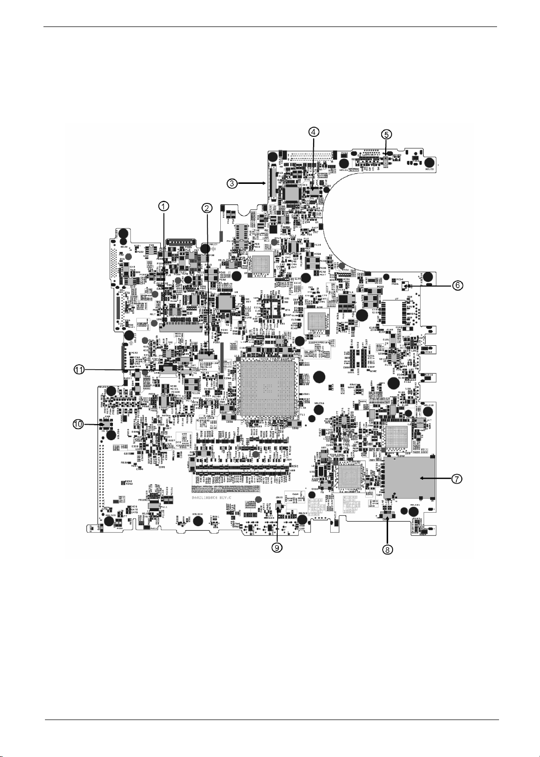
Board Layout
Top Vi e w
1 Keyboard Connector 7 3 in 1 Connector
2 Bluetooth Board Connector 8 Speaker Connector
3 LCD Cable Connector 9 Internal Microphone Connector
4 LED Board Connector 10 Modem Board Connector
5 Lid Switch 11 Touchpad Board Connector
6 Modem Cable Connector
4 Chapter 1
Page 15
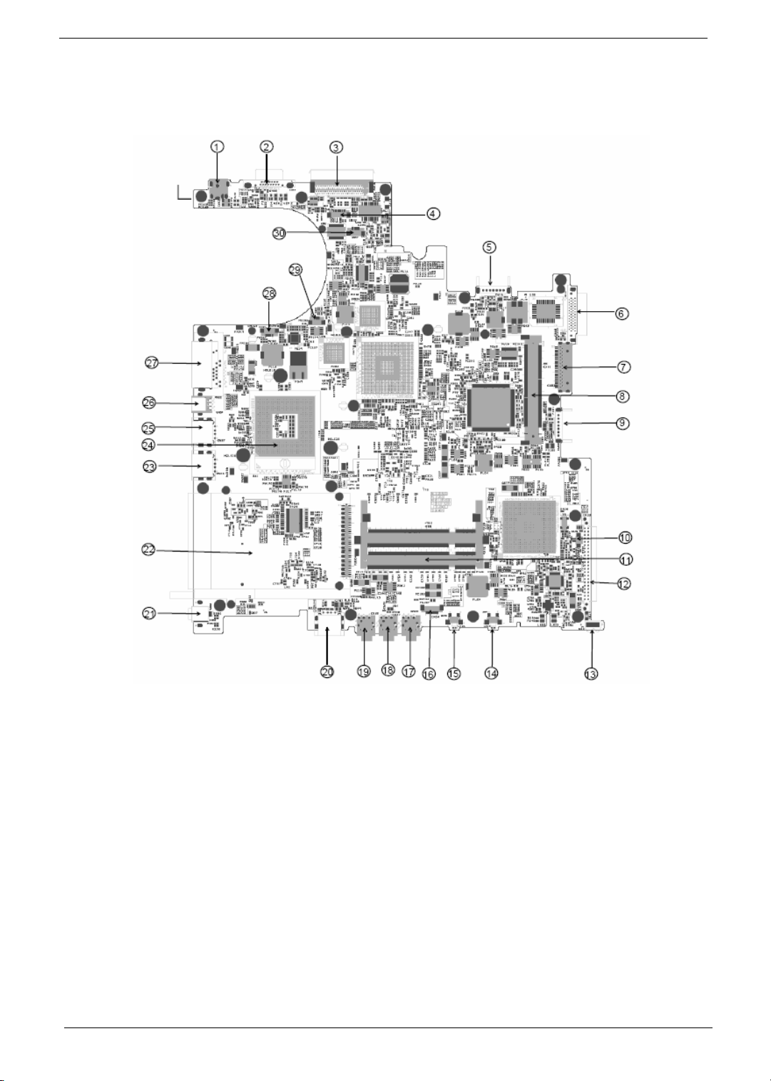
Bottom View
1 Power Jack 16 Audio Cable Connector
2 CRT 17 Line-in Connector
3 Docking 18 Headphone Out Connector
4 Audio Cable Connector 19 Microphone-in Connector
5 Main Battery Connector 20 USB Connector
6 ODD Connector 21 IEEE 1394 Connector
7 Media Bay Connector 22 PCMCIA
8 Mini PCI Slot 23 USB Connector
9 Second Battery Connector 24 CPU Socket
10 RTC Battery Connector 25 USB Connector
11 DDR DIMM Connector 26 S-Video
12 HDD Connector 27 RJ45 and RJ11 Connector
Chapter 1 5
Page 16

13 IR 28 LAN Cable Connector
14 Bluetooth Switch 29 FAN Connector
15 Wireless Switch 30 LAN Cable Connector
6 Chapter 1
Page 17
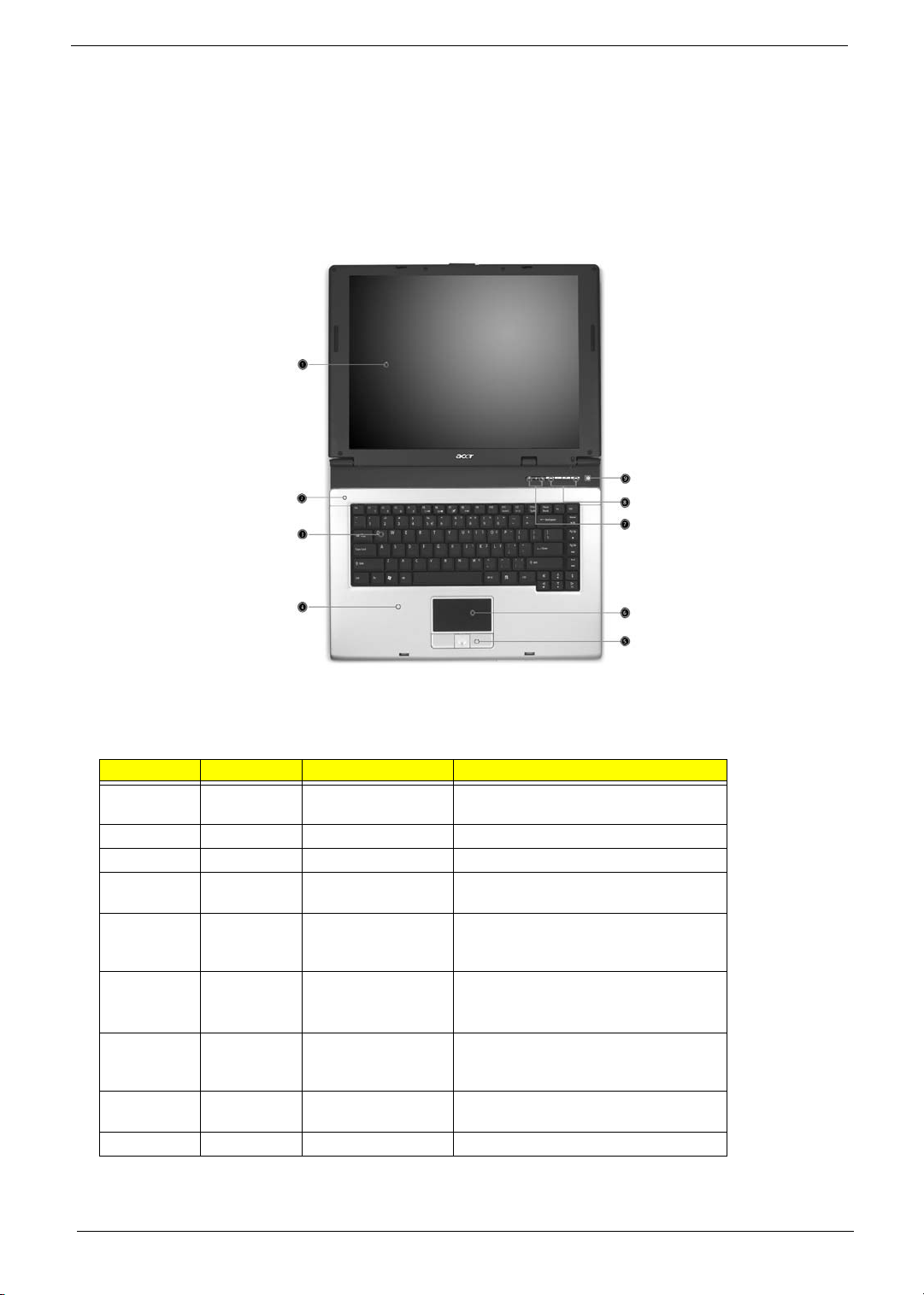
An Aspire Tour
After knowing your computer features, let us show you around your new Aspire computer.
Front View
# Icon Item Description
1 Display screen Also called LCD (liquid-crystal display),
2 Microphone Internal microphone for sound recording.
3 Keyboard Inputs data into your computer.
4 Palmrest Comfortable support area for our hands
5 Click buttons (Left,
center and right)
6 Touchpad Touch-sensitive pointing device which
7 Status indicators Light-Emitting Diodes (LEDs) that turn on
8 Launch keys Buttons for launching frequently used
9 Power button Turns the computer on and off.
displays computer output.
when you use the computer.
The left and right buttons function like the
left and right mouse buttons; the center
button serves as a 4-way scroll button.
functions like a computer mouse.
Turns on the computer power.
and off to show the status of the
computer’s function and components.
programs.
Chapter 1 7
Page 18
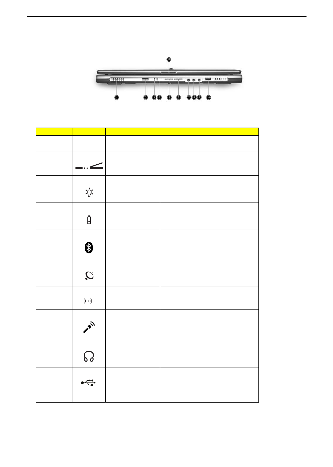
Closed Front View
# Icon Item Description
1 Speakers Left and right speakers deliver stereo audio
2 Infrared port
output.
Interfaces with infrared devices (e.g., infrared printer, IR-aware computer).
3 Power indicator
4 Battery indicator
5
6 Wireless
7 Line-in/Mic-in jack
8 Line-in/MIc-in jack
9 Speaker/Line-Out/
Bluetooth
communications
communication
Headphone jack
®
Lights when the computer is on.
Lights when the battery is being charged
Indicates that (optional) Bluetooth is
enabled.
Indicates status of wireless LAN communication.
Accepts audio line-in devices (e.g., audio
CD player, stereo walkman).
Accepts audio line-in devices (e.g., audio
CD player, stereo walkman).
Connects to audio line-out devices (e.g.,
speakers, headphones).
10 USB 2.0 port
11 Latch
Connects to Universal Serial Bus (USB) 2.0
devices (e.g., USB mouse, USB camera).
Locks and releases the lid.
NOTE: The Bluetooth and Wireless buttons and indicators only work on models with Bluetooth and Wireless
features, respectively.
8 Chapter 1
Page 19
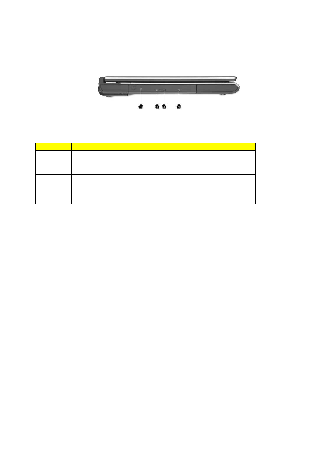
Left View
# Icon Item Description
1 Optical drive Internal optical drive; accepts CDs or DVDs
2 LED indicator Lights up when the optical drive is active.
3 Optical drive eject
4 Emergency eject hole Ejects the optical drive tray when the
depending on the optical drive type.
Ejects the optical drive is active.
button
computer is turned off.
Chapter 1 9
Page 20
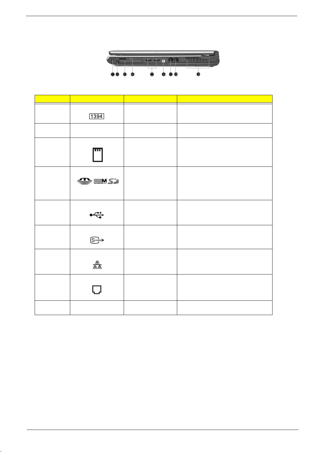
Right View
# Icon Item Description
1 IEEE 1394 port
(Manufacturing option)
Connects to IEEE 1394 devices.
2 PC Card slot eject
button
3 PC Card slot Connects to one Type II CardBus PC Card.
4 3-in-1 card reader Accepts MS, MMC and SD card.
5 Two USB 2.0 ports Connects to Universal Serial Bus (USB) 2.0
6 S-video port
(Manufacturing option)
7 Network jack Connect to an Ethernet 10/100-based
8 Modem jack
Ejects the PC Card from the slot.
Note: The 3-in-1 card reader is a
manufacturing option, subject to
configuration. Only one card can operate at
any given time.
devices (e.g., USB mouse, USB camera).
Connects to a television or display device
with S-video input.
network.
Connects to a phone line.
9 Ventilation slots Enable the computer to stay cool, even
after prolonged use.
10 Chapter 1
Page 21
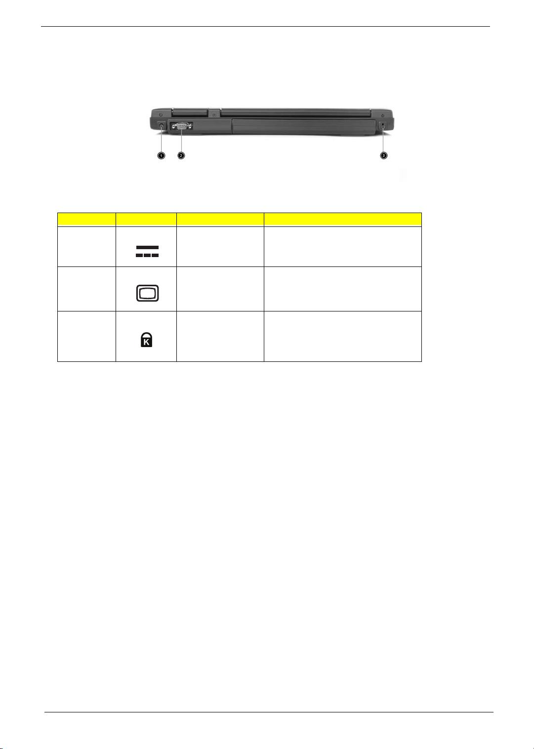
Rear Panel
# Icon Item Description
1 Power jace Connects to an AC adapter.
2 External display port Connects a display device (e.g., external
3 Security keylock Connects to a Kensington-compatible
monitor, LCD projector).
computer security lock.
Chapter 1 11
Page 22
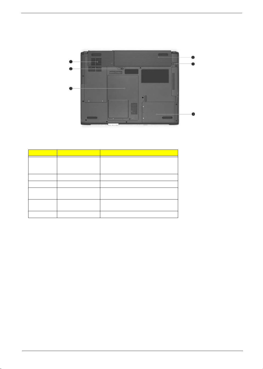
Bottom Panel
# Item Description
1 Cooling fan Helps keep the computer cool.
2 Battery lock Locks the battery in place.
3 Memory compartment Houses the computer’s main memory.
4 Hard disk bay Houses the computer’s hard disk (secured
6 Battery release latch Unlatches the battery to remove the battery
7 Battery bay Houses the computer’s battery pack.
Note: Do not cover or obstruct the opening
of the fan.
by a screw).
pack.
12 Chapter 1
Page 23
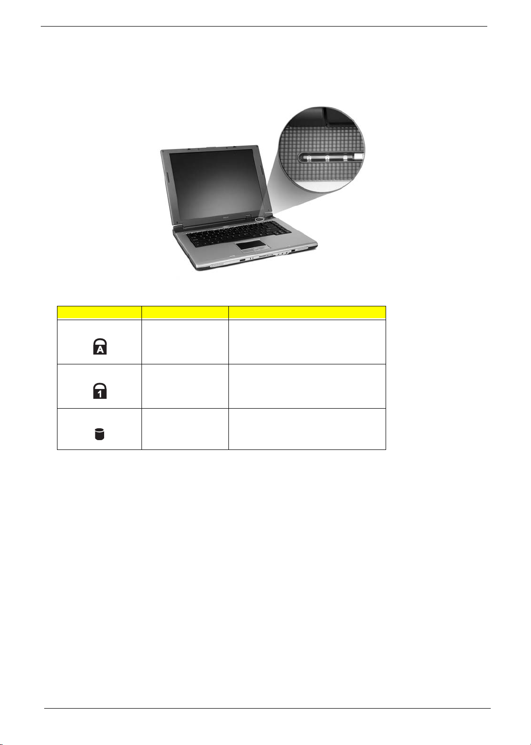
Indicators
The computer has three easy-to-read status icons on the upper-right above the keyboard.
Icon Function Description
Caps lock Lights when Caps Lock is activated.
Num lock Lights when Num Lock is activated.
Media Activity Lights when the hard disk or optical drive is
active.
Chapter 1 13
Page 24
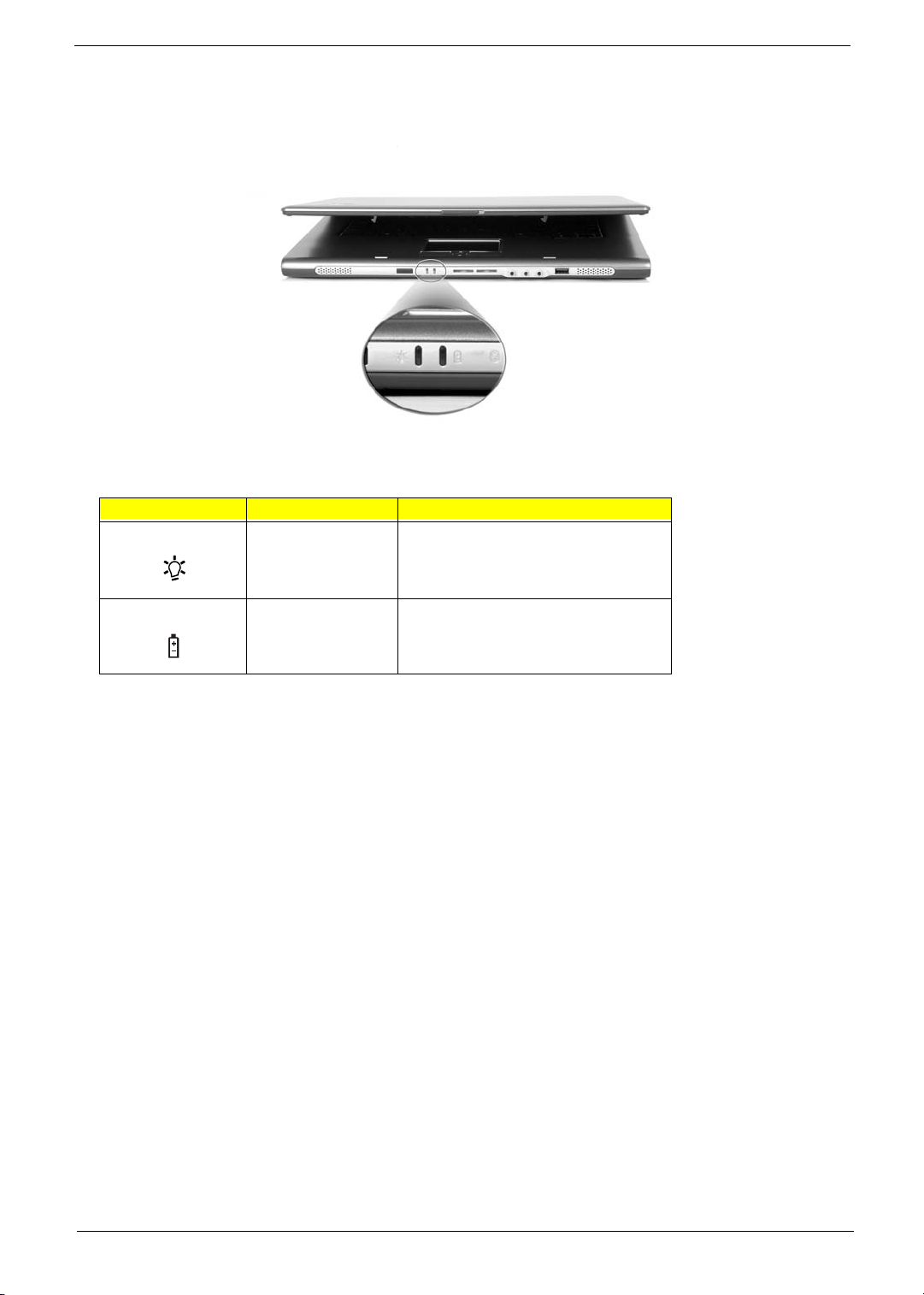
In addition, there are two indicators at the front panel. Even when the cover is closed, the state or features can
still be seen.
Icon Function Description
Power Lights when the computer is on.
Battery indicator Lights when the battery is being charged.
14 Chapter 1
Page 25
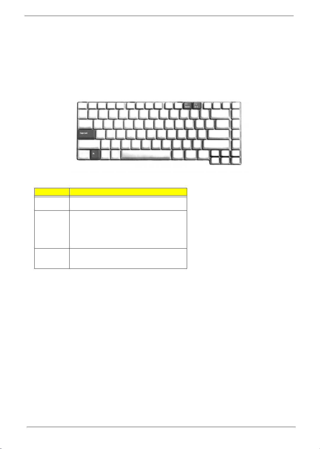
Using the Keyboard
The keyboard has full-sized keys and an embedded keypad, separate cursor keys, two Windows keys and
twelve function keys.
Lock Keys
The keyboard has three lock keys which you can toggle on and off.
Lock Key Description
Caps Lock When Caps Lock is on, all alphabetic characters typed
are in uppercase.
Num lock
(Fn-F11)
Scroll lock
(Fn-F12)
When Num Lock is on, the embedded keypad is in
numeric mode. The keys function as a calculator
(complete with the arithmetic operators +, -, *, and /).
Use this mode when you need to do a lot of numeric
data entry. A better solution would be to connect an
external keypad.
When Scroll Lock is on, the screen moves one line up
or down when you press w and y respectively.
Scroll Lock does not work with some applications.
Chapter 1 15
Page 26
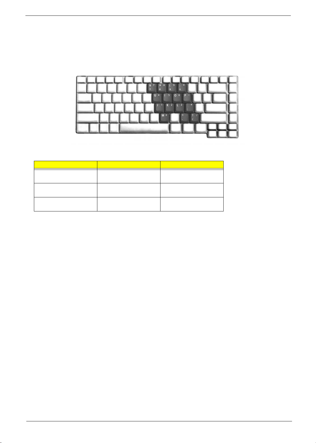
Embedded Numeric Keypad
The embedded numeric keypad functions like a desktop numeric keypad. It is indicated by small characters
located on the upper right corner of the keycaps. To simplify the keyboard legend, cursor-control key symbols
are not printed on the keys.
Desired Access Num Lock On Num Lock Off
Number keys on embedded
keypad
Cursor-control keys on
embedded keypad
Main keyboard keys Hold Fn while typing letters
Type numbers in a normal
manner.
Hold j while using
cursor-control keys.
on embedded keypad.
Hold Fn while using cursorcontrol keys.
Type the letters in a normal
manner.
16 Chapter 1
Page 27
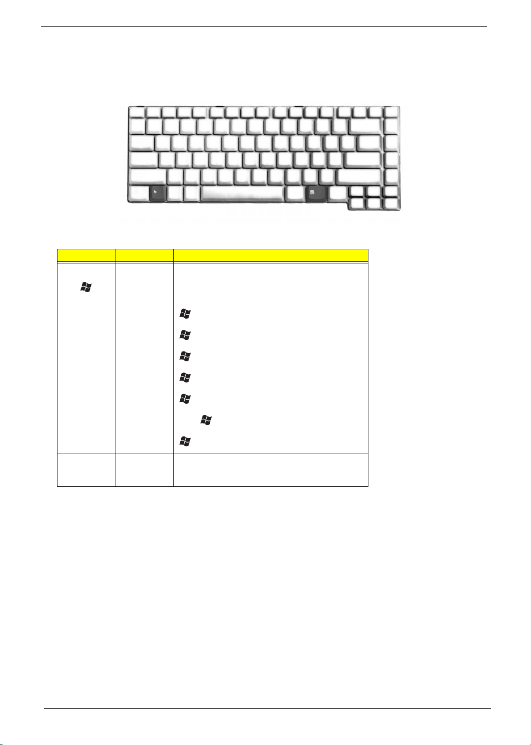
Windows Keys
The keyboard has two keys that perform Windows-specific functions.
Key Icon Description
Windows key Pressed alone, this key has the same effect as
clicking on the Windows Start button; it launches the
Start menu. It can also be used with other keys to
provide a variety of function:
+ Tab (Activates next taskbar button)
Application
key
+ E (Explores My Computer)
+ F1 (Opens Help and Support)
+ F (Opens the Find: All Files dialog box
+ M (Minimizes all windows)
j + + M (Undoes the minimize all windows)
+ R (Displays the Run... dialog box)
This key has the same effect as clicking the right
mouse button; it opens the application’s context
menu.
Chapter 1 17
Page 28
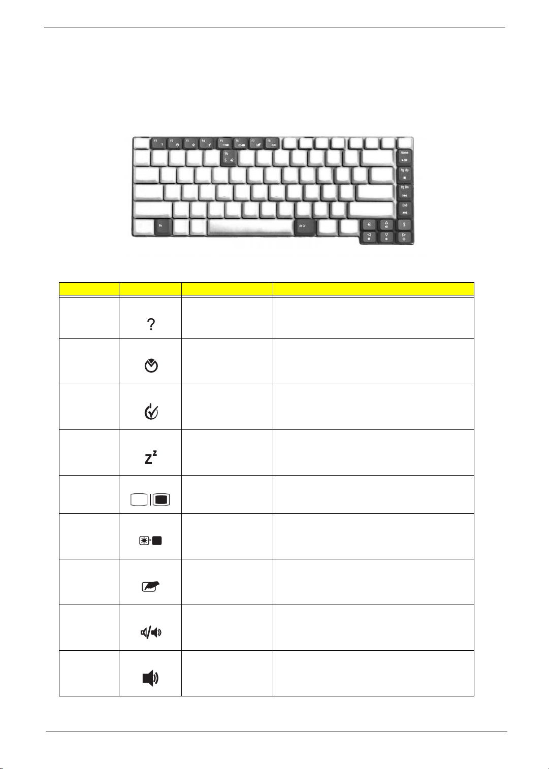
Hot Keys
The computer employs hot keys or key combinations to access most of the computer’s controls like sreen
brightness, volume output and the BIOS utility.
To activate hot keys, press and hold the Fn key before pressing the other key in the hot key combination.
Hot Key Icon Function Description
Fn-F1 Hot key help Displays help on hot keys.
Fn-F2 Acer eSetting Launches the Acer eSetting in the Acer eManager set
by the Acer Empowering key.
Fn-F3 Acer
ePowerManagement
Fn-F4 Sleep Puts the computer in Sleep mode.
Fn-F5 Display toggle Switches display output between the display screen,
Fn-F6 Screen blank Turns the display screen backlight off to save power.
Fn-F7 Touchpad toggle Turns the internal touchpad on and off.
Fn-F8 Speaker toggle Turns the speakers on and off.
Fn-w Volume up Increases the speaker volume.
Launches the Acer ePowerManagement in the Acer
eManager set by the Acer Empowering key.
external monitor (if connected) and both the display
screen and external monitor.
Press any key to return.
18 Chapter 1
Page 29
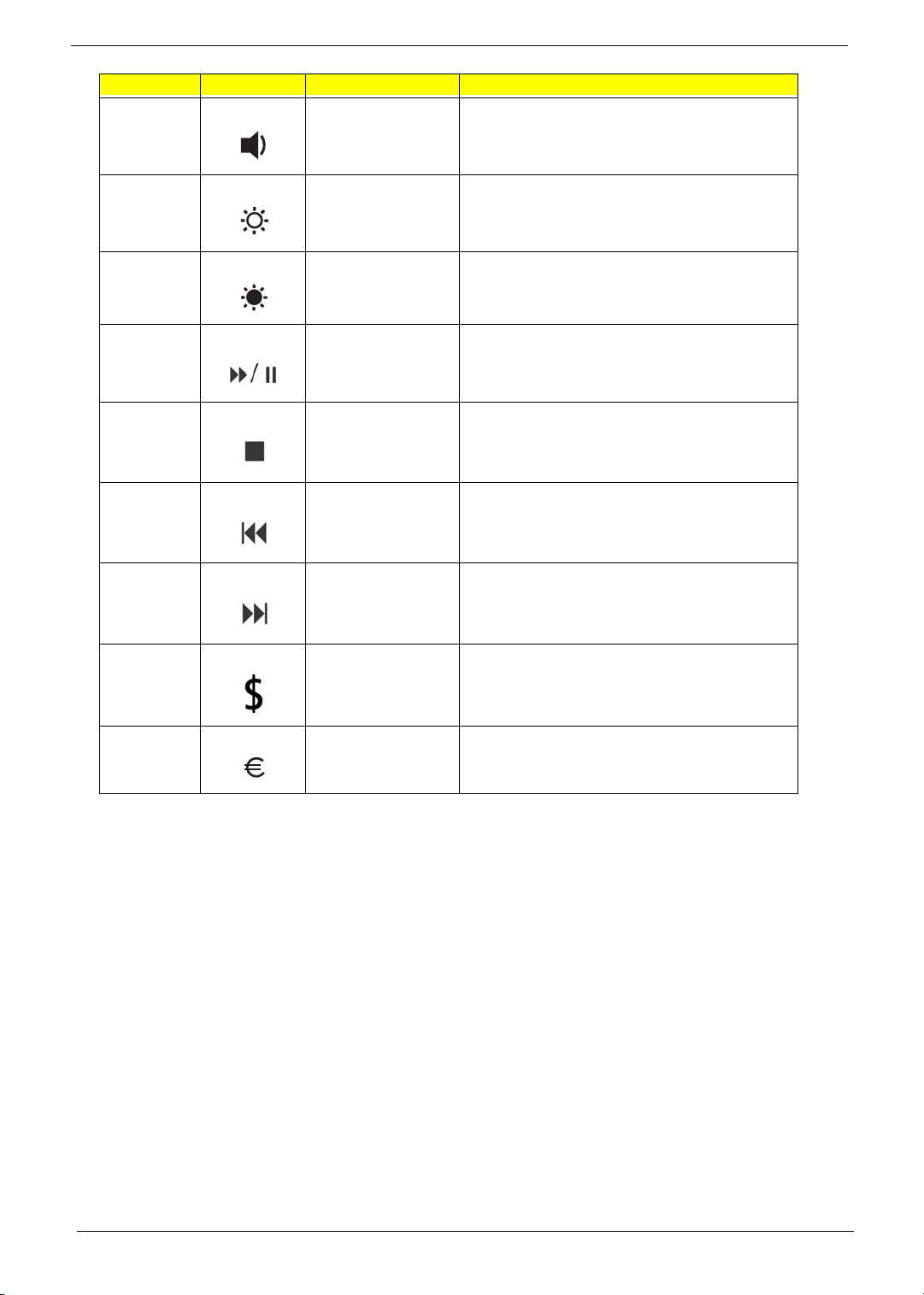
Hot Key Icon Function Description
Fn-y Volume down Decreases the speaker volume.
Fn-x Brightness up Increases the screen brightness.
Fn-z Brightness down Decreases the screen brightness
Fn-Home Play/Pause Press to start playing the audio track or video file.
Fn-Pg Up Stop Press to stop playing the audio track or video file.
Fn-Pg Dn Backwards Press to skip backward to the previous track or video
Fn-End Forward Press to skip forward to the next track or video file.
Alt Gr-$ US dollar Types the US dollar sign.
Alt Gr-Euro Euro Types the Euro symbol.
Press again to pause.
file and start playing.
Chapter 1 19
Page 30
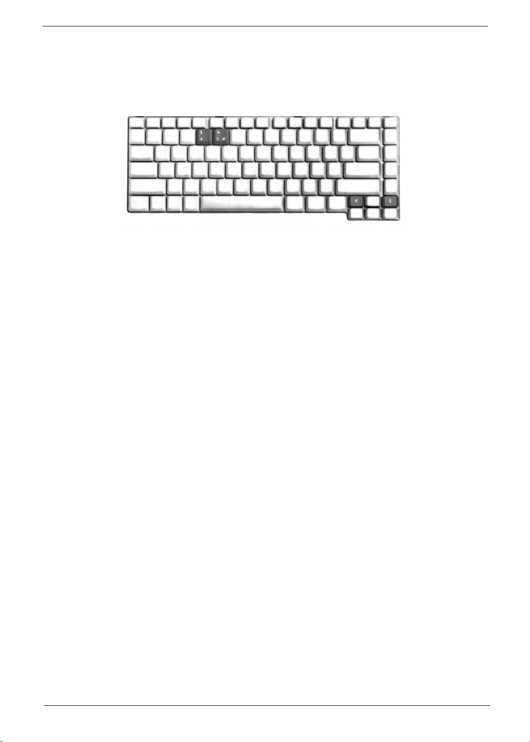
Special Key
You can locate the Euro symbol and US dollar sign at the upper-center and/or bottom-right of your keyboard.
To t y pe :
The Euro symbol
1. Open a text editor or word processor.
2. Either directly press the Euro symbol at the bottom-right of the keyboard, or hold Alt Gr and then press
the Euro symbol at the upper-center of the keyboard.
The US dollar sign
1. Open a text editor or word processor.
2. Either directly press the dollar sign at the bottom-right of the keyboard, or hold Alt Gr and then press the
dollar sign at the upper-center of the keyboard.
NOTE: This function varies by the operating system version.
20 Chapter 1
Page 31
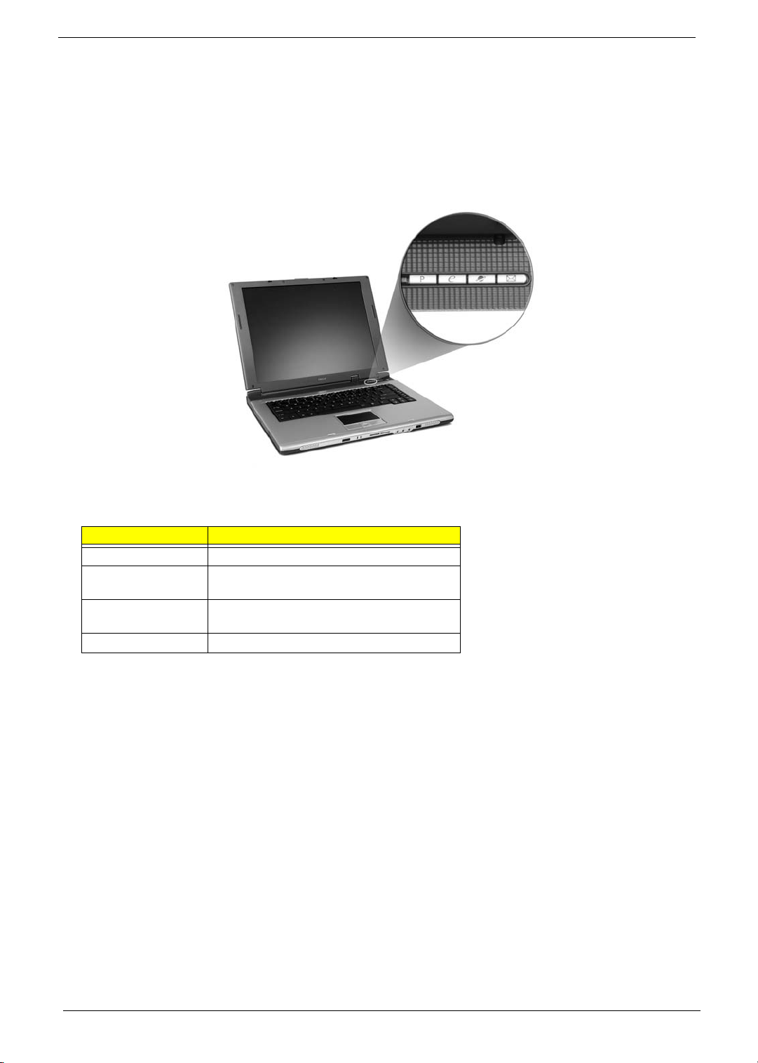
Launch Keys
Located at the upper-right above the keyboard are four buttons. These buttons are called launch keys. They
are designated as the mail, Web browser, Empowering and programmable keys.
Press the Acer Empowering Key to run the Acer EManager. The mail and Web browser are default for Email
and Internet programs, but can be reset by users. To set the mail, Web browser and programmable keys, run
the acer Launch Manager.
Launch Key Default application
Mail Email application (user-programmable)
Web browser Internet browser application (user
programmable)
e Acer eManager application (user-
programmable)
P User-programmable
Chapter 1 21
Page 32
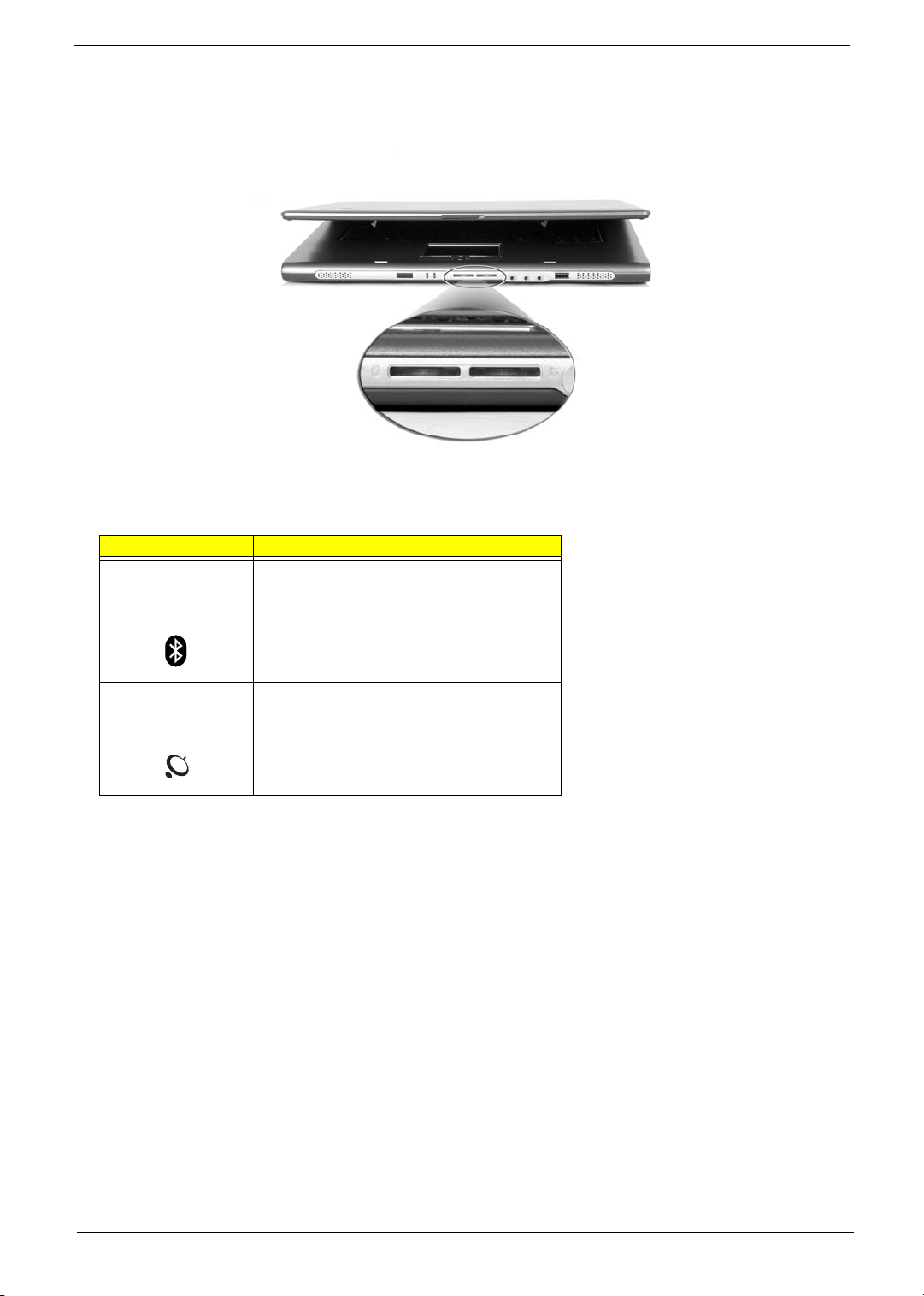
In addition, there are two launch keys at the front panel. Even when the cover is closed, you can easily access
the features of Wireless and Bluetooth
Description Default application
Bluetooth
communications
®
Lights to indicate the status of Bluetooth
(optional) communications.
®
. However, the Wireless and Bluetooth keys cannot be set by users.
Wireless
communications
Lights to indicate the status of wireless LAN
(optional) communications.
22 Chapter 1
Page 33
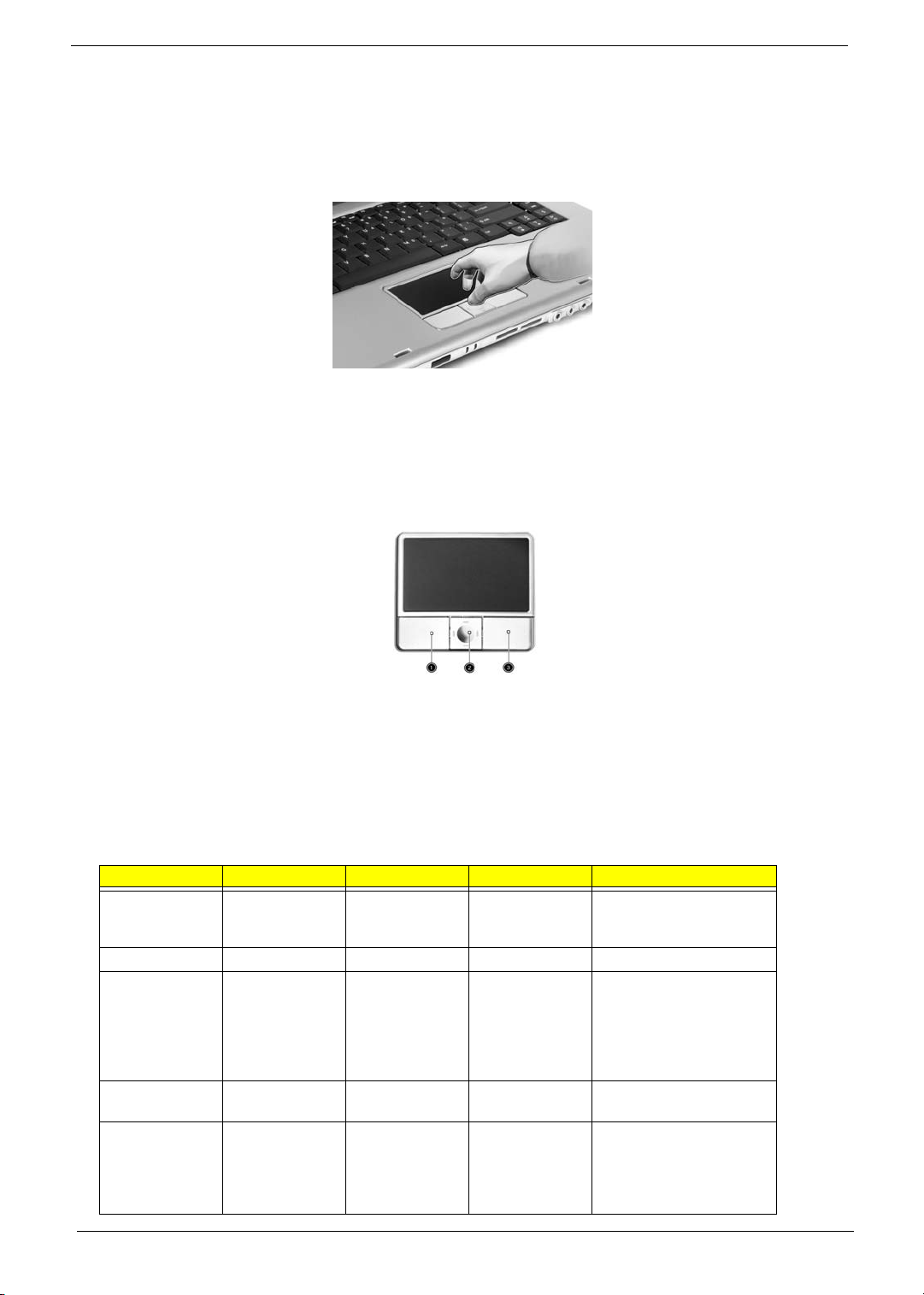
To u c h p a d
The built-in touchpad is a PS/2-compatible pointing device that senses movement on its surface. This means
the cursor responds as you move your finger on the surface of the touchpad. The central location on the
palmrest provides optimum comfort and support.
NOTE: If you are using an external USB or serial mouse, you can press Fn-F7 to disable the touchpad.
Touch pa d B asics
The following teaches you how to use the touchpad:
T Move your finger across the touchpad to move the cursor.
T Press the left (1) and right (3) buttons located on the edge of the touchpad to do selection and
execution functions. These two buttons are similar to the left and right buttons on a mouse.
Tapping on the touchpad produces similar results.
T Use the 4-way scroll (2) button (top/bottom/left/and right) to scroll.
Function Left Button Right Button Scroll Button Tap
Execute Click twice
quickly
Select Click once Tap once
Drag Click and hold,
then use finger
to drag the
cursor on the
touchpad
Access context
menu
Scroll Click and hold
Click once
the button in the
desired
direction (up/
down/left/right)
Tap twice (at the same
speed as double-clicking
the mouse button)
Tap twice (at the same
speed as double-clicking
a mouse button) then hold
finger to the touchpad on
the second tap to drag the
cursor
Chapter 1 23
Page 34

NOTE: Keep your fingers dry and clean when using the touchpad. Also keep the touchpad dry and clean. The
touchpad is sensitive to finger movements. Hence, the lighter the touch, the better the response.
Tapping too hard will not increase the touchpad’s responsiveness.
24 Chapter 1
Page 35
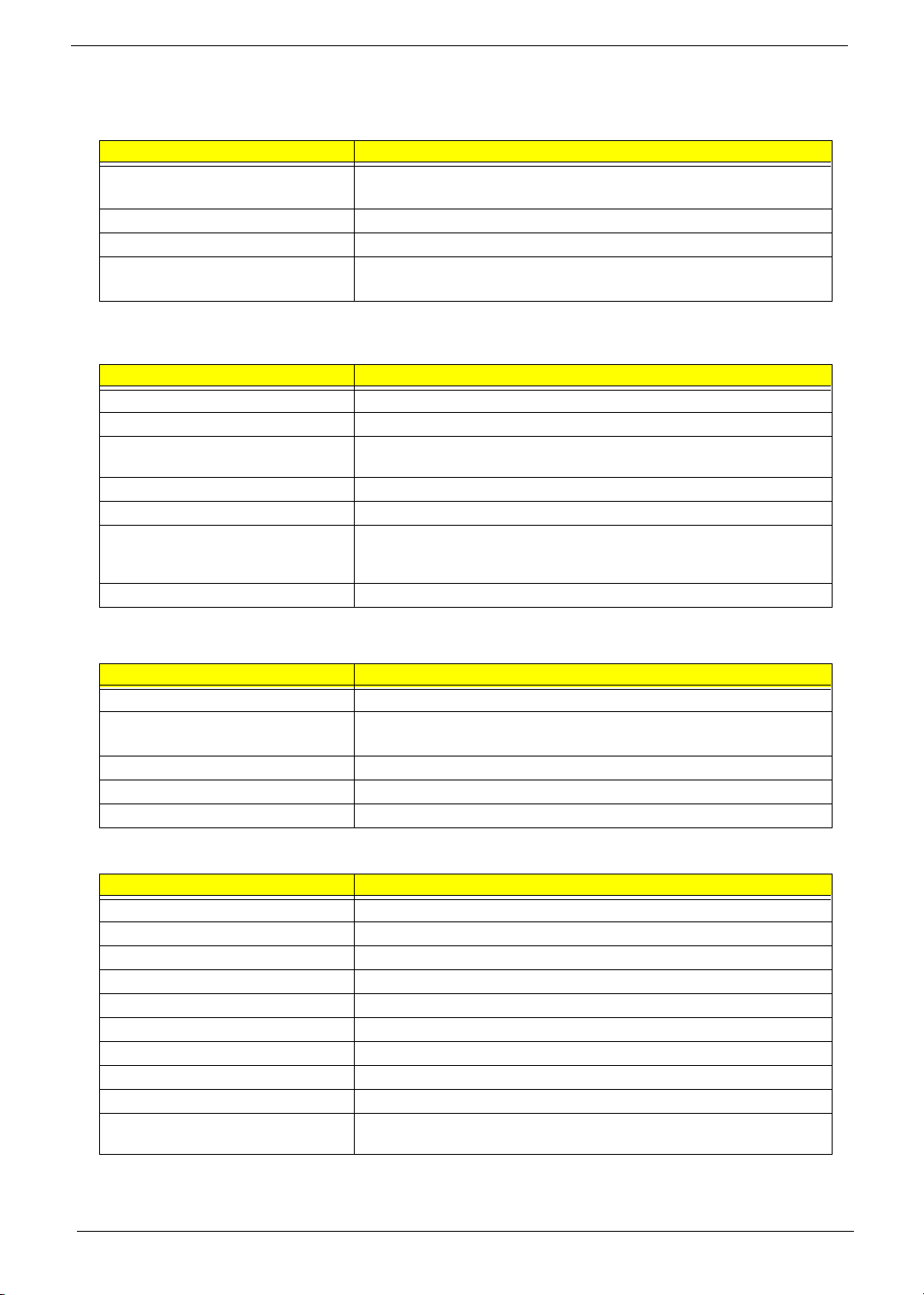
Hardware Specifications and Configurations
Processor
Item Specification
CPU type Intel Celeron M processor at 1.3GHz~1.4GHZ for Aspire 1410
Intel Pentim M processor at 1.5GHz~1.6GHz (Dothan) for Aspire 1680
Core logic Intel 855GME+ICH4
CPU package Intel socketable 478pin Micro-BGA
CPU core voltage 1.308V (highest frequency mode) to 0.956V (low frequency mode)
0.748V (deeper sleep mode)
BIOS
Item Specification
BIOS vendor Phneoix
BIOS Version 3A03
BIOS ROM type SST 39SF040A, 512KX8 CMOS Boot Block Flash Memory (the difference
with Flash ROM?)
BIOS ROM size 512KB
BIOS package 32-pin PLCC
Supported protocols ACPI 1.0b, PC Card 95, SM BIOS 2.3, IEEE1284-ECP/EPP, PCI 2.2, PnP
1.0a, DMI 2.0, PS/2 keyboard and mouse, USB 2.0, VGA BIOS, CD-ROM
bootable, IEEE 1394
BIOS password control Set by setup manual
Second Level Cache
Item Specification
Cache controller Built-in CPU
Cache size 512K for Intel Celeron M processor at 1.3~1.4GHz-Aspire 1410
2MB for Intel Pentium M processor at 1.5~1.6GHz (Dothan)-Aspire 1680
1st level cache control Always enabled
2st level cache control Always enabled
Cache scheme control Fixed in write-back
System Memory
Item Specification
Memory controller Intel 855GME built-in
Memory size 0MB (no on-board memory)
DIMM socket number 2 sockets
Supports memory size per socket 1024MB
Supports maximum memory size 2G (by two 1024MB SO-DIMM module)
Supports DIMM type DDR Synchronous DRAM
Supports DIMM Speed 333 MHz
Supports DIMM voltage 2.5V and 1.25V
Supports DIMM package 200-pin soDIMM
Memory module combinations You can install memory modules in any combinations as long as they
match the above specifications.
Chapter 1 25
Page 36
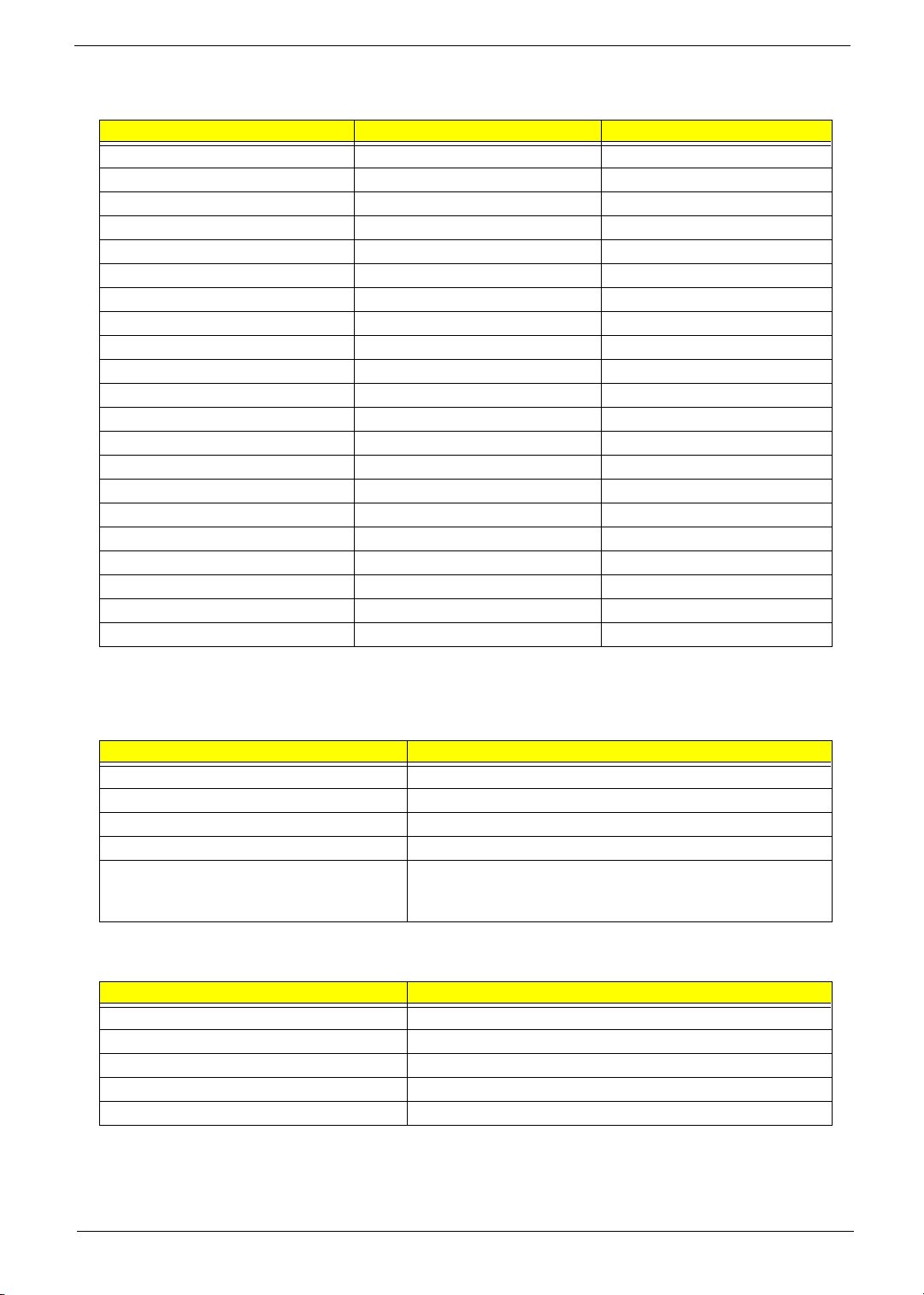
Memory Combinations
Slot 1 Slot 2 Total Memory
0MB 128MB 128MB
0MB 256MB 256MB
0MB 512MB 512MB
0MB 1024MB 1024MB
128MB 128MB 256MB
128MB 256MB 384MB
128MB 512MB 640MB
128MB 1024MB 1152MB
256MB 128MB 384MB
256MB 256MB 512MB
256MB 512MB 768MB
256MB 1024MB 1280MB
512MB 128MB 640MB
512MB 256MB 768MB
512MB 512MB 1024MB
512MB 1024MB 1536MB
1024MB 0MB 1024MB
1024MB 128MB 1125MB
1024MB 256MB 1280MB
1024MB 512MB 1536MB
1024MB 1024MB 2048MB
NOTE: Above table lists some system memory configurations. You may combine DIMMs with various
capacities to form other combinations. On above table, the configuration of slot 1 and slot 2 could be
reversed.
LAN Interface
Item Specification
Chipset Broadcom BCM4401 (10/100M); BroadCom BCM5788M (1G)
Supports LAN protocol 10/100/1000Mbps
LAN connector type RJ45
LAN connector location Right panel
Features Integrated 10/100 BASE-T transceiver
Wake on LAN support compliant with ACPI 2.0
PCI v2.2
IR Interface
Item Specification
Chipset
Part name VISHAY TFU6102F
Package 8-pin SMT type
Performance 4Mbit/s
Compliant IrDA 1.1
26 Chapter 1
Page 37
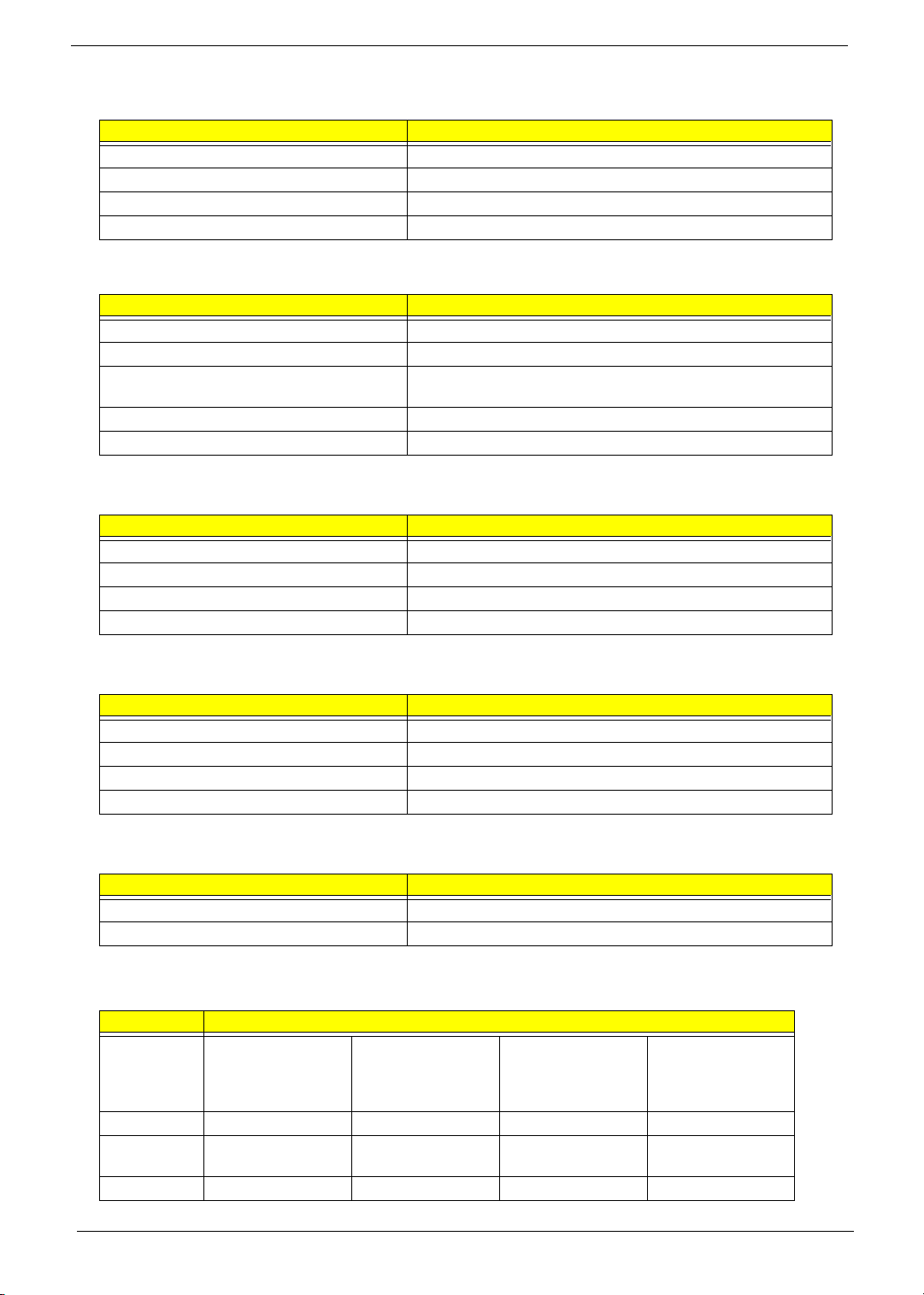
Modem Interface
Item Specification
Data modem data baud rate (bps) 56K
Supports modem protocol V.90/V.92
Modem connector type RJ11
Modem connector location Right panel
Bluetooth Interface
Item Specification
Chipset Broadcom BCM2035
Data throughput 723 bps(full speed data rate)
Protocol Bluetooth 1.1 (Upgradeable to Bluetooth 1.2 when SIG
specification is ratified).
Interface USB 1.1
Connector type Mini-USB
Wireless Module 802.11b/g (optional device)
Item Specification
Chipset Intel
Data throughput 11~54 Mbps
Protocol 802.11b+g
Interface Mini-PCI type II
Wireless Module 802.11a/b/g (optional device)
Item Specification
Chipset Intel
Data throughput 11~54 Mbps
Protocol 802.11 a+b+g
Interface Mini-PCI type II
3-in-1 card reader
Item Specification
Chipset TI PC7411
Protocol support Smart Media, Multi-Media Card and Security Digital
Hard Disk Drive Interface
Item Specification
Vendor &
Model Name
Capacity (MB) 30000 40000 60000 80000
Bytes per
sector
Data heads 2 2 3/4 (for Toshiba) 4
HGST
HTS424030M9AT00/
Toshiba Pluto
MK3025GAS/
512 512 512 512
HGST
HTS424040M9AT00/
Toshiba Pluto
MK4025GAS/
HGST MORAGA
IC25N060ATMR04-0
Toshiba Pluto
MK6025GAS
HGST MORAGA
IC25N080ATMR04-0
Toshiba Pluto
MK8025GAS
Chapter 1 27
Page 38
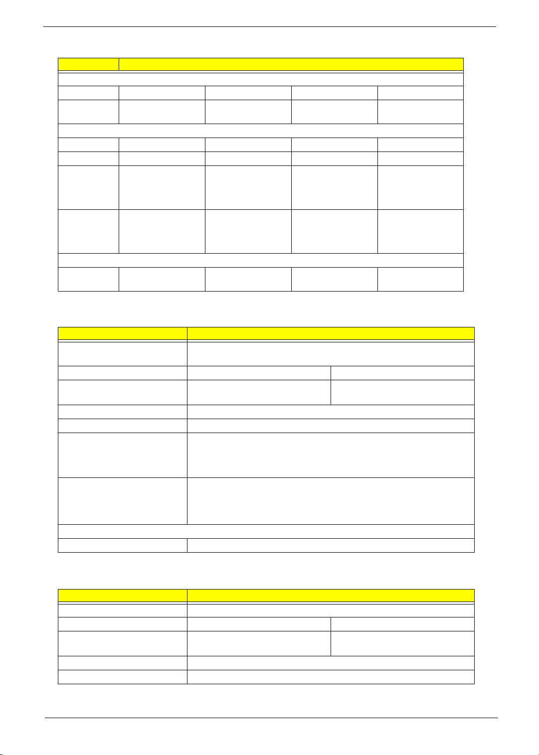
Hard Disk Drive Interface
Item Specification
Drive Format
Disks 1 1 2 2
Spindle speed
(RPM)
Performance Specifications
Buffer size 2048KB/ 2048KB 8192KB 8192KB
Interface ATA/ATAPI-6; ATA-6 ATA/ATAPI-6; ATA-6 ATA/ATAPI-6; ATA-6 ATA/ATA-6; ATA-6
Max. media
transfer rate
(disk-buffer,
Mbytes/s)
Data transfer
rate
(host~buffer,
Mbytes/s)
DC Power Requirements
Voltage
tolerance
4200 RPM 4200 RPM 4200 RPM 4200 RPM
372 372 350 350
100 MB/Sec.
Ultra DMA mode-5
5V(DC) +/- 5% 5V(DC) +/- 5% 5V(DC) +/- 5% 5V(DC) +/- 5%
100 MB/Sec.
Ultra DMA mode-5
100 MB/Sec.
Ultra DMA mode-5
100 MB/Sec.
Ultra DMA mode-5
Combo Drive Interface
Item Specification
Vendor & model name DVD/CDRW KME UIDA760 (24x24x8x24x)
DVD/CDRW QSI SBW-242C (24x24x8x24x)
Performance Specification With CD Diskette With DVD Diskette
Transfer rate (KB/sec) Sustained:
Max 3.6Mbytes/sec
Buffer Memory 2MB
Interface Enhanced IDE(ATAPI) compatible
Applicable disc format DVD: DVD-ROM, (DVD-5, DVD-9, DVD-10, DVD-18),DVD-R (read, single
border), DVD-RW, DVD-RAM (2.6GB, 4.7GB)
CD: CD-DA, CD-ROM, CD-ROM XA, CD-R, CD-RW Photo (Multisession)
Video CD, CD-Extra, (CD+), CD-test
Loading mechanism Load: Manual
Release: (a) Electrical Release (Release Button)
(b) Release by ATAPI command
(c) Emergency Release
Power Requirement
Input Voltage 5 V +/- 5 % (Operating)
Sustained:
Max 10.8Mbytes/sec
DVD-Dual Interface
Item Specification
Vendor & model name DVD Dual HLDS GWA-4040N
Performance Specification With CD Diskette With DVD Diskette
Transfer rate (KB/sec) Sustained:
Max 3.6Mbytes/sec
Buffer Memory 2MB
Interface Enhanced IDE(ATAPI) compatible
Sustained:
Max 10.8Mbytes/sec
28 Chapter 1
Page 39
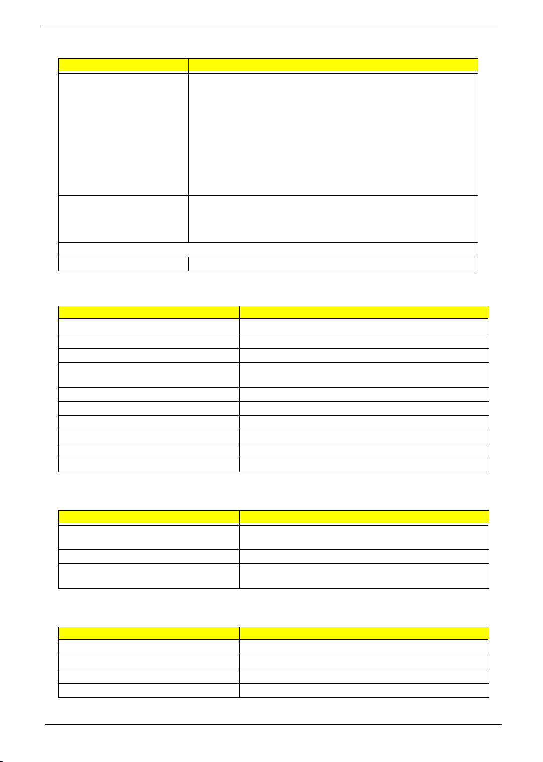
DVD-Dual Interface
Item Specification
Applicable disc format Support disc formats
1. Reads data in each CD-ROM, CD-ROM XA, CD-1, Video CD, CD-Extra and
CD-Text
2. Reads data in Photo CD (single and Multi-session)
3. Reads standard CD-DA
4. Reads and writes CD-R discs
5. Reads and writes CD-RW discs
6. Reads and writes in each dVD+R/RW (Ver. 1.1)
7. Reads data in each DVD-ROM and DVD-R (Ver. 2.0 for Authoring)
8. Reads and writes in each DVD-R (Ver. 2.0 for general), DVD-RW and
DVD+R/RW (Ver1.1)
Loading mechanism Load: Manual
Release: (a) Electrical Release (Release Button)
(b) Release by ATAPI command
(c) Emergency Release
Power Requirement
Input Voltage 5 V +/- 5 % (Operating)
Audio Interface
Item Specification
Audio Controller Conexant CX20468-31
Audio onboard or optional Built-in
Mono or Stereo Stereo
Resolution 18 bit stereo Digital to analog converter
18 bit stereo Analog to Ditial converter
Compatibility AC97
Mixed sound source Line-in, CD
Voice channel 8/16-bit, mono/stereo
Sampling rate 44,1 KHz (48K byte for AC97 interface)
Internal microphone Yes
Internal speaker / Quantity Yes/2
Audio Jack
Item Specification
Number of audio jack Internal: 2
External:3
Rated input 1W
Connector type Internal: two 1W speakers
External: Headphone out, microphone in and line-in
Video Interface
Item Specification
Chipset ATI Mobility RADEON 9700
Package MBGA 708 pin
Interface AGP8X
Supports ZV (Zoomed Video) port Yes
Chapter 1 29
Page 40
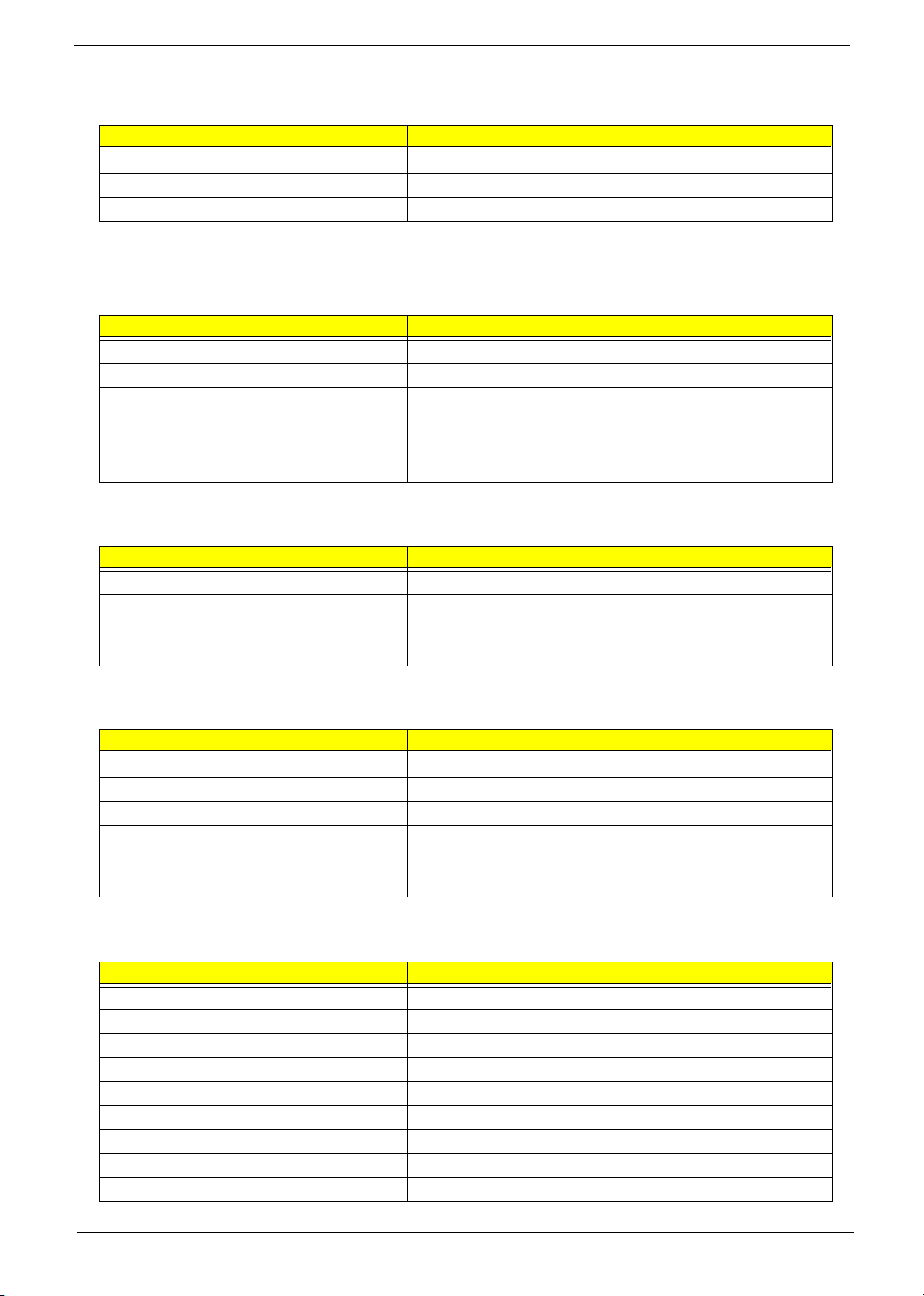
Video Memory
Item Specification
Chipset Intel 855GME/ATI M11P (ATI Mobility RADEON 9700)
Memory size UMA 16/32/64MB, discrete 64MB
Interface DDR
USB Port
Item Specification
Chipset ICH4-M
USB Compliancy Level 2.0
OHCI USB 1.1 and USB 2.0 Host controller
Number of USB port 3
Location two on the right side; one on the front side
Serial port function control Enable/Disable by BIOS Setup
IEEE 1394 Port
Item Specification
Chipset TI PC7411
Number of IEEE 1394 port 1
Location Right side
Connector type IEEE 1394
PCMCIA Port
Item Specification
PCMCIA controller TI PC7411
Supports card type Type-II
Number of slots One type-II
Access location Right panel
Supports ZV (Zoomed Video) port No ZV support
Supports 32 bit CardBus Yes
System Board Major Chips
Item Controller
Core logic Intel 855GME+ICH4
VGA ATI Mobility RADEON 9700
LAN BroadCom BCM4401 (10/100M); BCM5788M(1G)
IEEE 1394 TI PC7411
USB 2.0 ICH4-M
Super I/O controller NS 87383
MODEM Conexant CX20468-31
Bluetooth Broadcom BCM2035
Wireless 802.11 b Intel
30 Chapter 1
Page 41
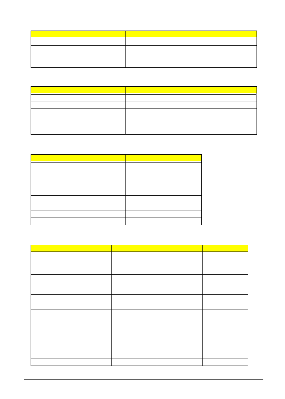
System Board Major Chips
Item Controller
Wireless 802.11 b+g Intel
PCMCIA TI PC7411
Audio Conexant RD01-D620
3-in-1 card reader TI PC7411
Keyboard
Item Specification
Keyboard controller NS PC97551
Total number of keypads 88-/89-key
Windows logo key Yes
Internal & external keyboard work
simultaneously
1. Plug USB keyboard to the USB port directly: Yes
2. Use port replicator then plug a USB/PS 2 keyboard to the USB
port/PS 2 port on the port replicator: Yes
Battery
Item Specification
Vendor & model name Sanyo 4UR18650F-2-QC140
Panasonic CGR-B/8B5AE
Simplo 916-3020
Battery Type Li-ion
Pack capacity 4400 mAh
Number of battery cell 8
Package configuration 4 cells in series, 2 series in parallel
Normal voltage 14.4V
Charge voltage 16.8+-0.2v
LCD 14.1 inch for Aspire 1410
Item Specification
Vendor & model name AU B141XG05 CMO N141XB-L01 QDI QD141XLH12
Screen Diagonal (mm) 357(14.1inch) 14inch 360(14.1inch)
Active Area (mm) 285.7(H)x214.3(V) 285.7(H)x214.3(V) 285.7(H)x214.3(V)
Display resolution (pixels) XGA (1024x768) XGA (1024x768) XGA (1024x768)
Pixel Pitch 0.279(H)x0.279(H)mm0.279(H)x0.279(H)
mm
Pixel Arrangement RGB vertical stripe RGB vertical stripe RGB vertical stripe
Display Mode Normally white Normally white Normally white
Typical White Luminance (cd/m
also called Brightness
Luminance Uniformity 1.2(5 points)
Contrast Ratio 250 (min)/ 300 (typ) 300(min)/450(typ) 300(min)
Response Time (Optical Rise Time/Fall
Time)msec
Nominal Input Voltage VDD +3.3V not show +3.3V
2
)
150
1.5(13 points)
15/10 6/17(typ)
130(min)/160(typ)
not show 1.45(5 points)
10/25(max)
0.279(H)x0.279(H)
mm
120
2(13 points)
12.5/22.5
Chapter 1 31
Page 42
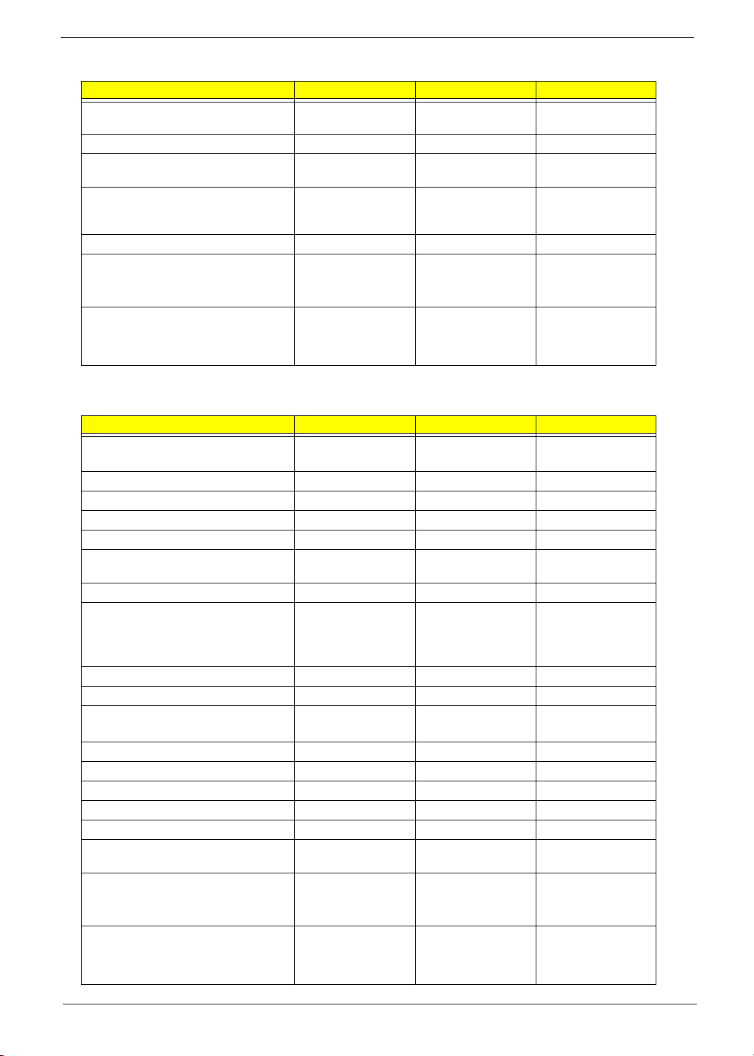
LCD 14.1 inch for Aspire 1410
Item Specification
Typical Power Consumption (watt) 5.3 4.03 (for backlight
unit)
Weight 400g (w/o inverter) 420g 460g
Physical Size(mm) 299(W)x228(H)x5.5
Electrical Interface R/G/B Data, 3Sync,
Support Color Native 262K colours 262K colours 262K colours
Viewing Angle (degree)
Horizontal: Right/Left
Vertial: Upper/Lower
Temperature Range( C)
Operating
Storage (shipping)
°
(D)
Signals, Clock (4
pairs LVDS)
45/45
15/35
0 to +50
-20 to +60
299(W)x228(H)x5.2
(D)
1 channel LVDS 1 channel LVDS
45/45
15/35
0 to +50
-20 to +60
N/A
299(W)x228(H)x6.2
(D)
40/40
10/30
0 to +50
-25 to +60
LCD 15 inch
Item Specification
Vendor & model name AU:
B150XG01
Screen Diagonal (mm) 381 15.0 inches 15.0 inches
Active Area (mm) 304.1x228.1 304.1x228.1 304.1x228.1
Display resolution (pixels) 1024x768 XGA 1024x768 XGA 1024x768 XGA
Pixel Pitch 0.297x0.297 0.099x0.297 0.297x0.297
Pixel Arrangement R.G.B. Vertical
Stripe
Display Mode Normally White Normally White Normally White
2
Typical White Luminance (cd/m
also called Brightness
Luminance Uniformity N/A N/A 70
Contrast Ratio 300 300 250
Response Time (Optical Rise Time/Fall
Time)msec
Nominal Input Voltage VDD +3.3V Typ. +3.3V 3.3V
Typical Power Consumption (watt) 5.6/5.7 3.96 N/A
Weight 550 570 600
Physical Size(mm) 317.3x242.0x6.0 317.3x242.0x5.9 317.3x242.0x6.5
Electrical Interface 1 channel LVDS 1 channel LVDS 1 channel LVDS
Support Color 262K colors (RGB
Viewing Angle (degree)
Horizontal: Right/Left
Vertial: Upper/Lower
Temperature Range( C)
Operating
Storage (shipping)
°
)
180 (5 point
average)
150 (5 point
average)
24/11
15/35
6-bit data driver)
40/40
10/30
0 to +50
-20 to +60
QDI
QD15XL06-01
R.G.B. Vertical
Stripe
160 150
8/17 10/25
262,144 262,144
45/45
15/35
0 to +50
-25 to +60
Hannstar
HSD150PX14-A07
R.G.B. Vertical
Stripe
40/40
20/40
0 to +50
-20 to +60
32 Chapter 1
Page 43
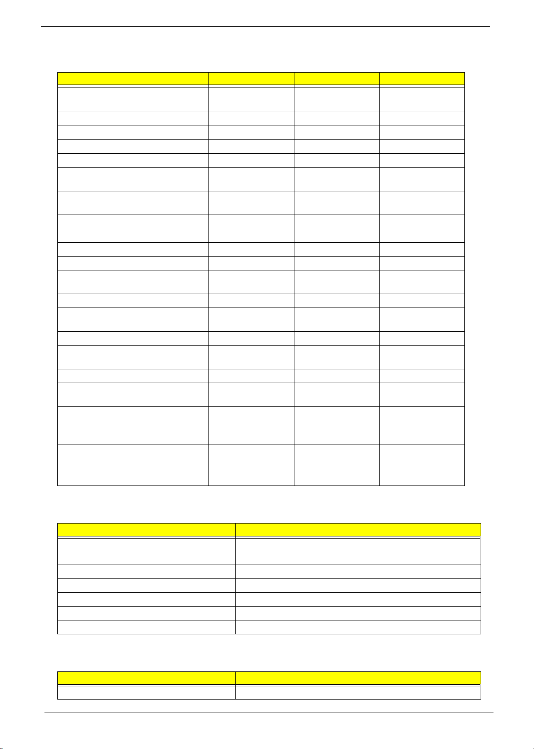
LCD 15 inch and 15.4 inch
Item Specification
Vendor & model name SAMSUNG
LTN150XB-L03
Screen Diagonal (mm) 15.0 inches, 381 390.1
Active Area (mm) 304.1x228.1 304.1x228.1 331.2x207.0
Display resolution (pixels) 1024x768 XGA 1024x768 XGA 1280x800 WXGA
Pixel Pitch 0.297x0.297 0.297x0.297 0.2588x0.2588
Pixel Arrangement R.G.B. Vertical
Stripe
Display Mode Normally White Transmissive &
Typical White Luminance (cd/m
also called Brightness
Luminance Uniformity N/A 40 1.4 (5pts)
Contrast Ratio 200 200 400
Response Time (Optical Rise Time/Fall
Time)msec
Nominal Input Voltage VDD +3.3V +3.3V +3.3V Typ.
Typical Power Consumption (watt) 4.6 for backlight unit
Weight 585 580 585
Physical Size(mm) 317.3x242.1x6.0 317.3x242.1x6.0 344x222.0x6.35
Electrical Interface 1 channel LVDS 1 channel LVDS 1 channel LVDS
Support Color 262K 262K 262K colors (RGB
Viewing Angle (degree)
Horizontal: Right/Left
Vertial: Upper/Lower
Temperature Range( C)
Operating
Storage (shipping)
°
2
)
160 170 185
10/30(typ) 30/30 5/20
only
45/45
25/45
N/A
Hitachi
TX38D81VC1CAB
R.G.B. Vertical
Stripe
normally White
N/A 4.38
40/40
20/40
0 to +40
-20 to +60
LCD 15.4" WXGA
QDI
R.G.B. Vertical
Stripe
Normally White
max
6-bit data driver)
15/35
45/45
0 to +50
-25 to +60
LCD Inverter
Item Specification
Vendor & model name SUMIDA TWS-449-147
Brightness conditions Vadj=3.3V
Input voltage (V) 8~20
Input current (mA) 350 (max)
Output voltage (V, rms) 1600 (no load)
Output current (mA, rms) 5.6~5.4
Output voltage frequency (k Hz) 55~58K Hz
AC Adaptor
Item Specification
Input rating 90V AC to 264V AC, 47Hz to 63Hz
Chapter 1 33
Page 44
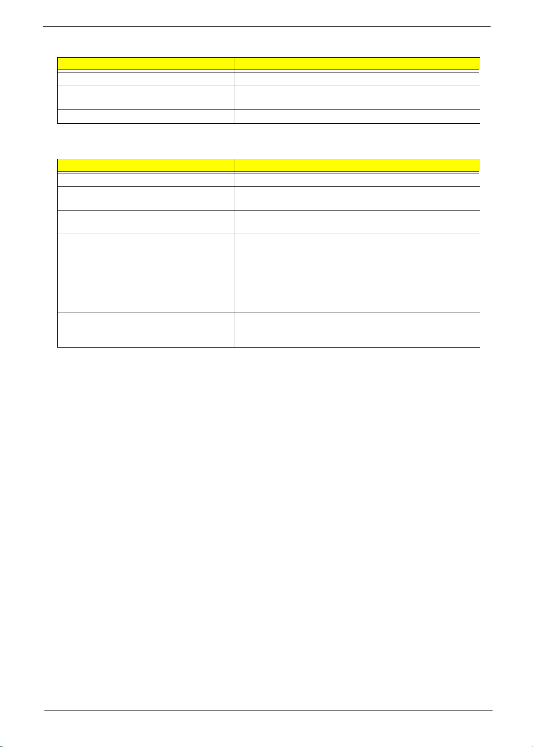
AC Adaptor
Item Specification
Maximum input AC current 3.42A
Inrush current 220A@115VAC
220A@230VAC
Efficiency 82% min. @115VAC input full load
System Power Management
ACPI mode Power Management
Mech. Off (G3) All devices in the system are turned off completely.
Soft Off (G2/S5) OS initiated shutdown. All devices in the system are turned off
completely.
Working (G0/S0) Individual devices such as the CPU and hard disc may be power
managed in this state.
Suspend to RAM (S3) CPU set power down
VGA Suspend
PCMCIA Suspend
Audio Power Down
Hard Disk Power Down
CD-ROM Power Down
Super I/O Low Power mode
Save to Disk (S4) Hibernation Mode
Also called Hibernate state. System saves all system states and
data onto the disc prior to power off the whole system.
34 Chapter 1
Page 45

Chapter 1 35
Page 46

→
Chapter 2
System Utilities
BIOS Setup Utility
The BIOS Setup Utility is a hardware configuration program built into your computer’s BIOS (Basic Input/
Output System).
Your computer is already properly configured and optimized, and you do not need to run this utility. However, if
you encounter configuration problems, you may need to run Setup. Please also refer to Chapter 4
Troubleshooting when problem arises.
To activate the BIOS Utility, press
on the bottom of screen).
Press m to enter setup. The default parameter of F12 Boot Menu is set to “disabled”. If you want to change
boot device without entering BIOS Setup Utility, please set the parameter to “enabled”.
Press <F12> during POST to enter multi-boot menu. In this menu, user can change boot device without
entering BIOS SETUP Utility.
. Info. Main Advanced Security Boot Exit
CPU Type: Intel (R) Pentium (R) M processor 1.70Ghz
CPU Speed:
HDD1 Model Name:
HDD1 Serial Number:
HDD2 Model Name:
HDD2 Serial Number:
ATAPI Device:
System BIOS Ver:
VGA BIOS Ver:
KBC Ver:
Serial Number
Asset Tag Number: 1234567890
Product Aspire1680
Manufacturer Name: Acer
UUID:
F1 Help ↑↓ Select Item F5/F6 Change Values F9 Setup Defaults
Esc Exit ←
1700 MHz
IC25N080ATMR04-0
MPAA01Q2G0746A
MATSHITADVD-RAM UJ-825S
3A01
Montara-GME3360
PQ1A24
1234567890123456789012
xxxxxxxxxxxxxxxxxxxxxxxxxxxxxxxx
Select Menu Enter Select 4Sub-Menu F10 Save and Exit
m during POST (when “Press <F2> to enter Setup” message is prompted
PhoenixBIOS Setup Utility
Chapter 2 36
Page 47

Navigating the BIOS Utility
There are six menu options: Info., Main, System Devices, Security, Boot, and Exit.
Follow these instructions:
T To choose a menu, use the cursor left/right keys (zx).
T To choose a parameter, use the cursor up/down keys ( wy).
T To change the value of a parameter, press por q.
T A plus sign (+) indicates the item has sub-items. Press e to expand this item.
T Press ^ while you are in any of the menu options to go to the Exit menu.
T In any menu, you can load default settings by pressing t. You can also press u to save any
changes made and exit the BIOS Setup Utility.
NOTE: You can change the value of a parameter if it is enclosed in square brackets. Navigation keys for a
particular menu are shown on the bottom of the screen. Help for parameters are found in the Item
Specific Help part of the screen. Read this carefully when making changes to parameter values. Please
note that system information vary in models.
37 Chapter 2
Page 48
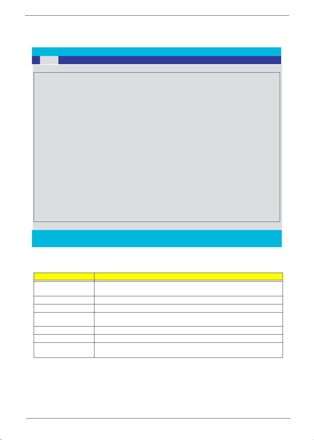
Information
→
PhoenixBIOS Setup Utility
. Info. Main Advanced Security Boot Exit
CPU Type: Intel (R) Pentium (R) M processor 1.70Ghz
CPU Speed:
HDD1 Model Name:
HDD1 Serial Number:
HDD2 Model Name:
HDD2 Serial Number:
ATAPI Device:
System BIOS Ver:
VGA BIOS Ver:
KBC Ver:
Serial Number
Asset Tag Number: 1234567890
Product Aspire1680
Manufacturer Name: Acer
UUID:
F1 Help ↑↓ Select Item F5/F6 Change Values F9 Setup Defaults
Esc Exit ←
1700 MHz
IC25N080ATMR04-0
MPAA01Q2G0746A
MATSHITADVD-RAM UJ-825S
3A01
Montara-GME3360
PQ1A24
1234567890123456789012
xxxxxxxxxxxxxxxxxxxxxxxxxxxxxxxx
Select Menu Enter Select 4Sub-Menu F10 Save and Exit
NOTE: The system information is subject to different models.
Parameter Description
Floppy Disk Drive Shows floppy drive type informaiton only when this model has floppy disk drive.
HDD Model Name This field shows the model name of HDD installed on primary IDE master.
HDD Serial Number This field displays the serial number of HDD installed on primary IDE master.
ATAPI Model Name This field displays the mofel name of devices installed on secondary IDE master. The hard
disk drive or optical drive model name is automatically detected by the system.
ATAPI Serial Number This field shows the serial number of devices installed on secondary IDE master.
Serial Number This field displays the serial number of this unit.
UUID Number This will be visible only when an internal LAN device is presenting.
UUID=32bytes
Chapter 2 38
Page 49
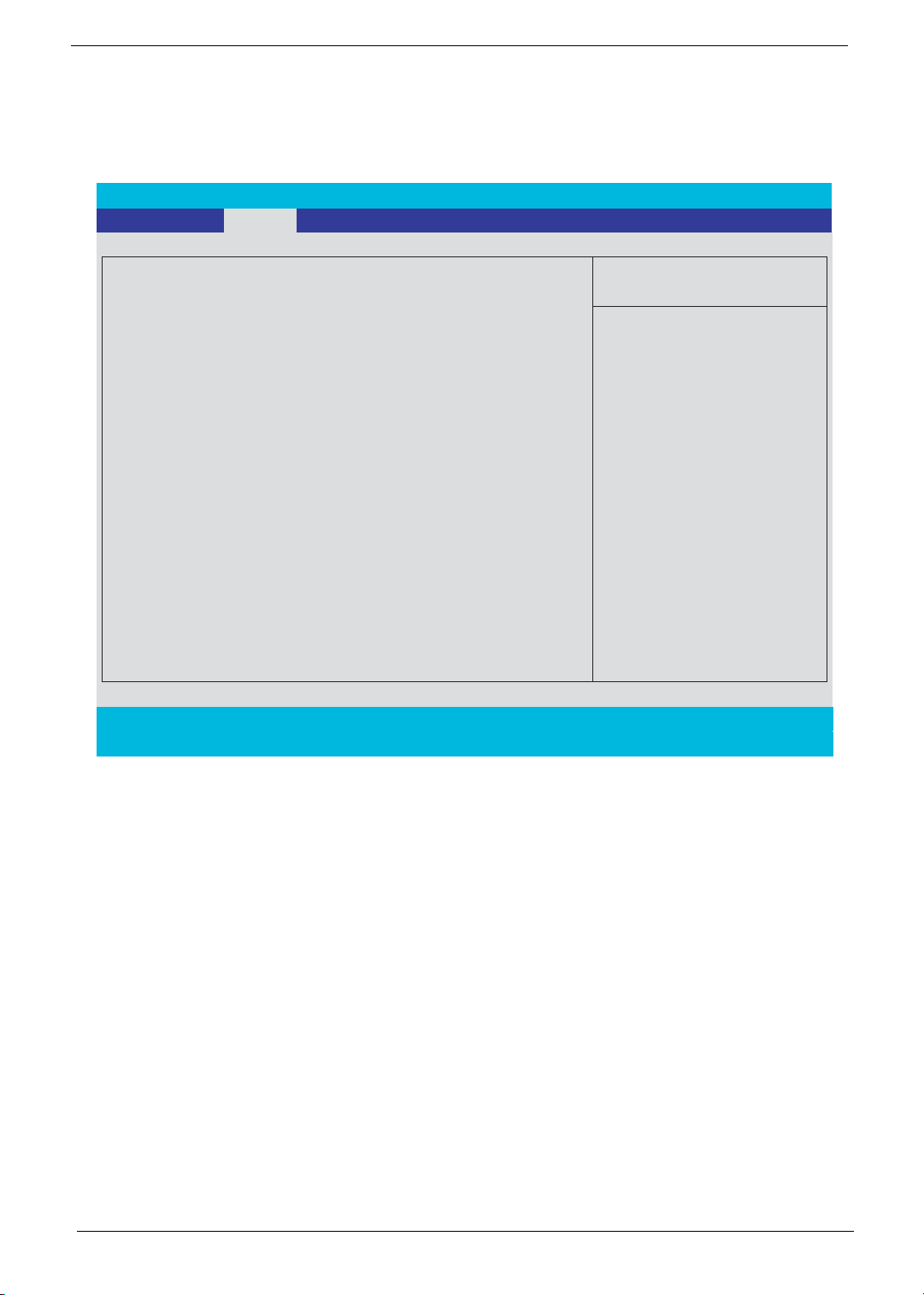
Main
The Main screen displays a summary of your computer hardware information, and also includes basic setup
parameters. It allows the user to specify standard IBM PC AT system parameters.
PhoenixBIOS Setup Utility
Info.
Main
Advanced Security Boot Exit
Item Specific Help
System Time: [05:34:07]
System Date: [07/23/2004]
System Memory: 640 KB
Extended Memory: 238MB
Video Memory [16MB]
Shows system base memory size
Shows extended memory size
VGA memory size
<Tab>, <Shift-Tab>, or
<Enter> selects field.
Quiet Boot: [Enabled]
Power on Display: [Auto ]
Network boot:
F12 Boot Menu:
D2D recovery:
[Enabled]
[Disabled]
[Enabled]
F1 Help ↑↓ Select Item F5/F6 Change Values F9 Setup Defaults
Esc Exit ← → Select Menu Enter Select 4Sub-Menu F10 Save and Exit
NOTE: The screen above is for reference only. Actual values may differ.
39 Chapter 2
Page 50
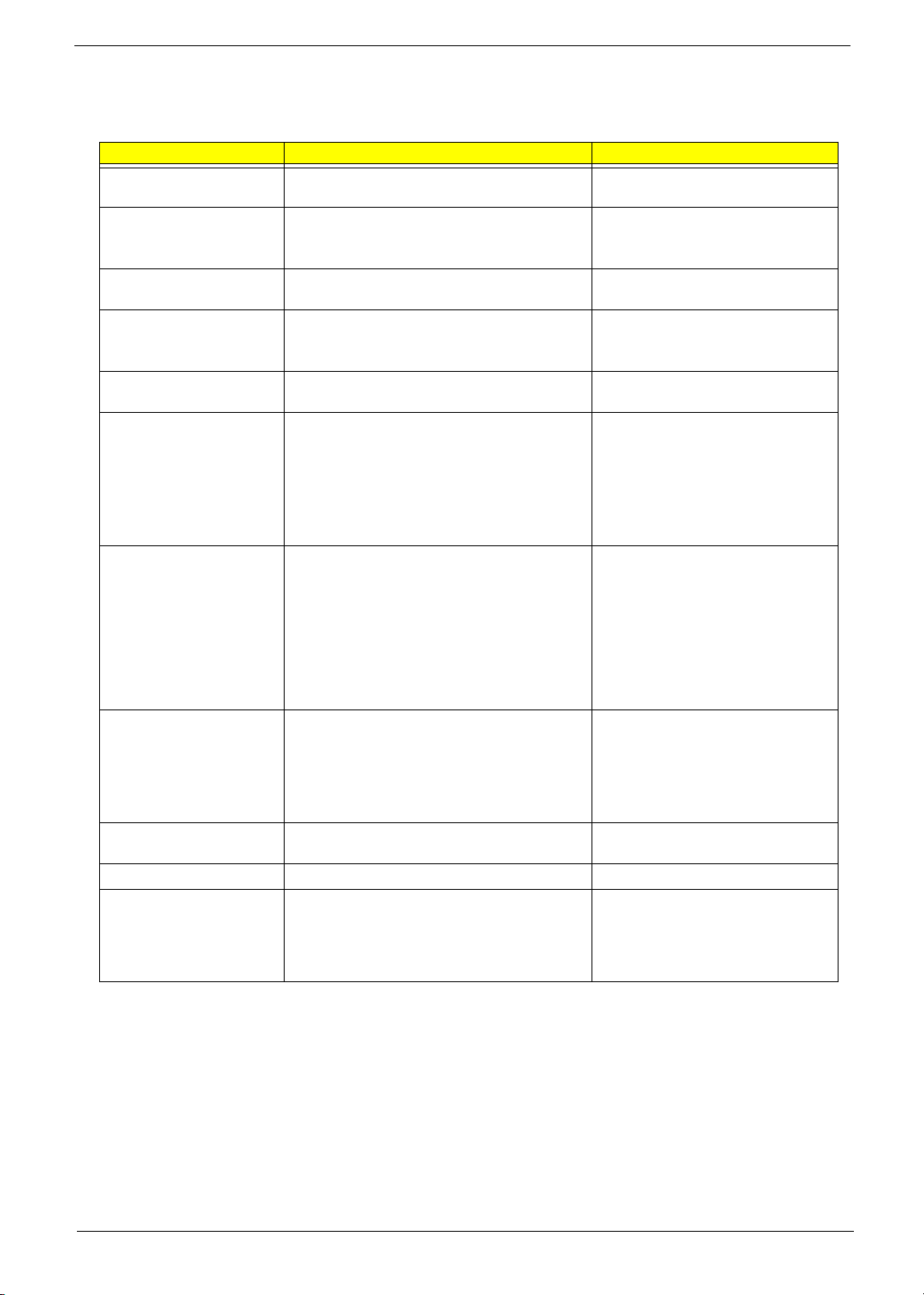
The table below describes the parameters in this screen. Settings in boldface are the default and suggested
parameter settings.
Parameter Description Format/Option
System Time Sets the system time. The hours are displayed
with 24-hour format.
System Date Sets the system date. Format MM/DD/YYYY (month/day/
System Memory This field reports the memory size of the system.
Memory size is fixed to 640MB
Extended Memory This field reports the memory size of the
extended memory in the system.
Extended Memory size=Total memory size-1MB
VGA Memory Shows the VGA memory size. VGA Memory
size=64/128MB
Fast Boot Determines if Customer Logo will be displayed or
not; shows Summary Screen is disabled or
enabled.
Enabled: Customer Logo is displayed, and
Summary Screen is disabled.
Disabled: Customer Logo is not displayed, and
Summary Screen is enabled.
Power on display Auto: During power process, the system will
detect if any display device is connected on
external video port. If any external display device
is connected, the power on display will be in CRT
(or projector) only mode. Otherwise it will be in
LCD only mode.
Both: Simultaneously enable both the integrated
LCD screen and the system’s external video port
(for an external CRT or projector).
LCD Auto Dim Determines if the system will automatically dim
the LCD brightness in order to save power when
AC is not present.
The system will support an automatic dimming of
the LCD backlight when the AC power is NOT
available (running on battery power).
Network Boot Enables, disables the system boot from LAN
(remote server).
F12 Boot Menu Enables, disables Boot Menu during POST.
D2D Recovery Enables, disables D2D Recovery function. The
function allows the user to create a hidden
partition on hard disc drive to store operation
system and restore the system to factory
defaults.
Format: HH:MM:SS
(hour:minute:second) System Time
year)
System Date
Option: Enabled or Disabled
Option:
Auto or Both
Option:
Enabled or Disabled
Enabled or Disabled
Option:
Option:
Disabled or Enabled
Option:
Enabled or Disabled
NOTE: The sub-items under each device will not be shown if the device control is set to disable or auto. This is
because the user is not allowed to control the settings in these cases.
Chapter 2 40
Page 51
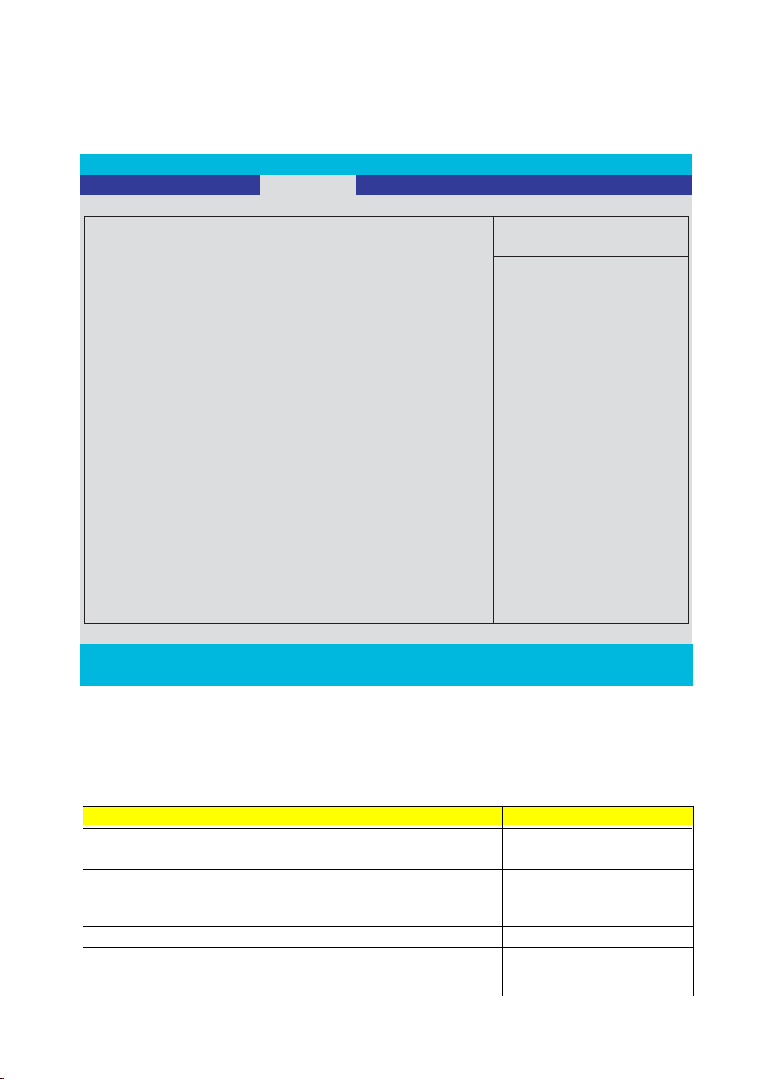
Advanced
The Advanced menu screen contains parameters involving your hardware devices. It also provides advanced
settings of the system.
PhoenixBIOS Setup Utility
Info. Main Advanced Security Boot Exit
Item Specific Help
Internal Touchpad:
Infrared Port (FIR):
[Both]
[Enabled]
Configure Infrared Port
using options:
[Disable]
No configuration
[Enabled]
User configuration
[Auto]
BIOS or OS chooses
configuration
(OS Controlled)
Displayed when controlled
by OS
F1 Help ↑↓ Select Item F5/F6 Change Values F9 Setup Defaults
Esc Exit ← → Select Menu Enter Select 4Sub-Menu F10 Save and Exit
The table below describes the parameters in the screen. Settings in boldface are the default and suggested
parameter settings.
.
Parameter Description Options
Infrared Port Enables, disables or auto detects the infrared port.
Parallel Port Enables, disables or auto detects the parallel port.
Mode Sets the operation mode of the parallel port.
Base I/O address Sets the I/O address of the parallel port.
Interrupt Sets the interrupt request of the parallel port.
DMA channel Sets a DMA channel for the printer to operate in
ECP mode. This parameter is enabled only if Mode
is set to ECP.
41 Chapter 2
Disabled/Disabled/Auto
Enabled/Disabled/Auto
ECP, EPP, Output only or Bi-
directional
378/278
IRQ7/IRQ5
DMA3/DMA1
Page 52
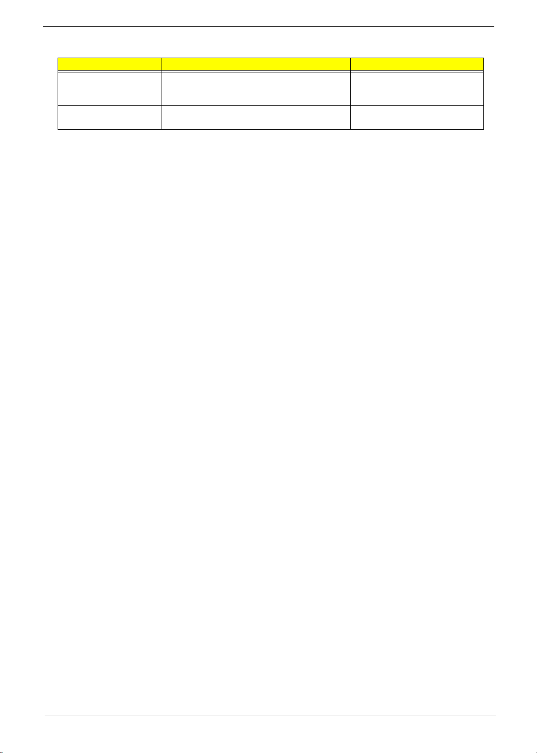
Parameter Description Options
Legacy USB Support Enables, disables USB interface devices support.
(Enable for use with a non-USB aware Operating
System such as DOS or UNIX).
Hard Disk Recovery Enables or disables Hard Disk to Hard Disk system
Recovery by pressing Fn+F10 key during POST.
Option:
Option:
Disabled or Enabled
Disabled or Enabled
Chapter 2 42
Page 53
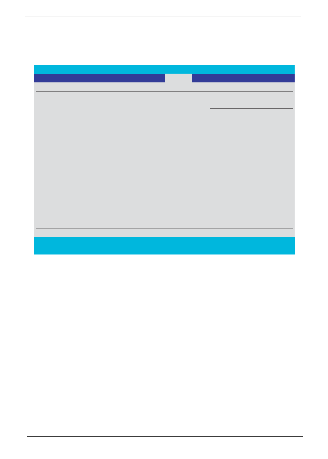
Security
The Security screen contains parameters that help safeguard and protect your computer from unauthorized
use.
PhoenixBIOS Setup Utility
Info. Main Advanced Boot
Security
Item Specific Help
Exit
Supervisor Password Is: Clear
User Password Is: Clear
Primary HardDisk Security:
HDD Master ID:
Set Supervisor Password
Set User Passord
Set HDD Password
Clear
43883445
[Enter]
[Enter]
[Enter]
When shown as [Locked],
the hard drive password
currently can not be changed
or disabled.
To change or disable it, turn
off the system and enter Setup
immediately after turning it
Password on Boot
[Disabled]
back on.
Press [Enter] to input, change,
or disable hard drive
passwords.
F1 Help ↑↓ Select Item F5/F6 Change Values F9 Setup Defaults
Esc Exit ← → Select Menu Enter Select 4Sub-Menu F10 Save and Exit
43 Chapter 2
Page 54
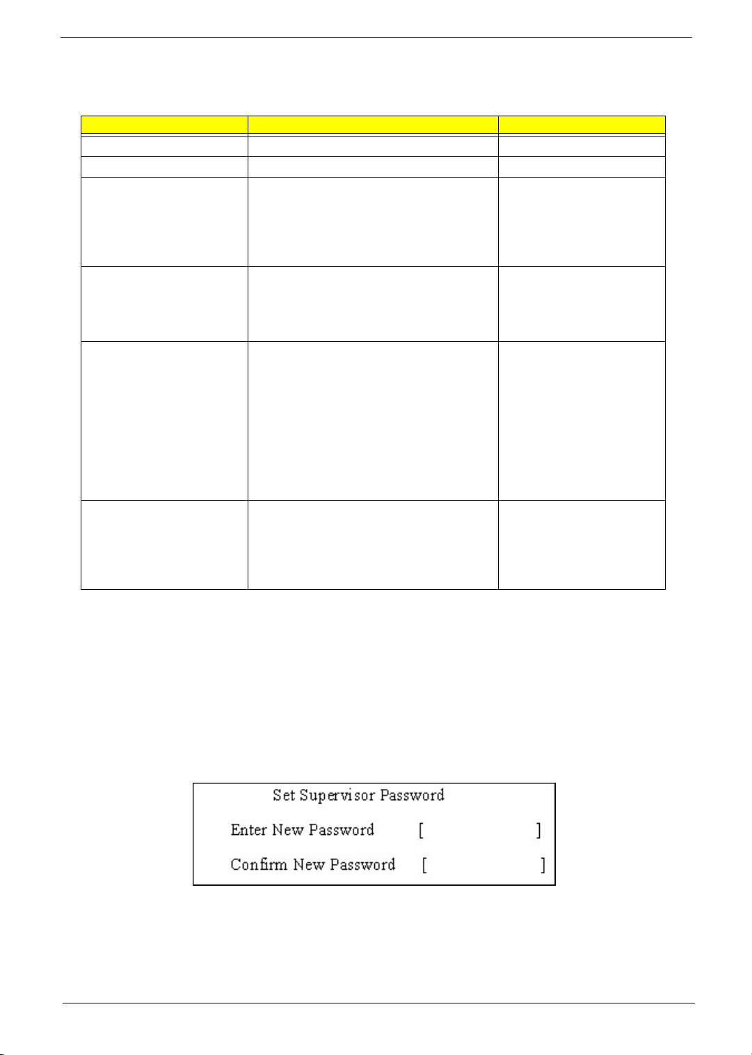
The table below describes the parameters in this screen. Settings in boldface are the default and suggested
parameter settings.
Parameter Description Option
User Password is Shows the setting of the user password.
Supervisor Password is Shows the setting of the Supervisor password
Set User Password Press Enter to set the user password. When
user password is set, this password protects
the BIOS Setup Utility from unauthorized
access. The user can enter Setup menu only
and does not have right to change the value of
parameters.
Set Supervisor Password Press Enter to set the supervisor password.
When set, this password protects the BIOS
Setup Utility from unauthorized access. The
user can not either enter the Setup menu nor
change the value of parameters.
Primary Harddisk Security This feature is available to user when
Supervisor password is set. Password can be
written on HDD only when Supervisor
password or user password is set and
password on HDD is set to enabled.
Supervisor Password is written to HDD only
when Supervisor password is being set. User
password is written to HDD when both
passwords are set. When both Supervisor and
user password are present, both passwords
can unlock the HDD.
Password on Boot Defines whether a password is required or not
while the events defined in this group
happened. The following sub-options are all
requires the Supervisor password for changes
and should be grayed out if the user password
was used to enter setup.
Clear or Set
Clear or Set
Disabled or Enabled
Disabled or Enabled
NOTE: When you are prompted to enter a password, you have three tries before the system halts. Don’t forget
your password. If you forget your password, you may have to return your notebook computer to your
dealer to reset it.
Setting a Password
Follow these steps as you set the user or the supervisor password:
1. Use the w andy keys to highlight the Set Supervisor Password parameter and press the e key. The
Set Supervisor Password box appears:
2. Type a password in the “Enter New Password” field. The password length can not exceeds 8
alphanumeric characters (A-Z, a-z, 0-9, not case sensitive). Retype the password in the “Confirm New
Password” field.
IMPORTANT:Be very careful when typing your password because the characters do not appear on the screen.
Chapter 2 44
Page 55
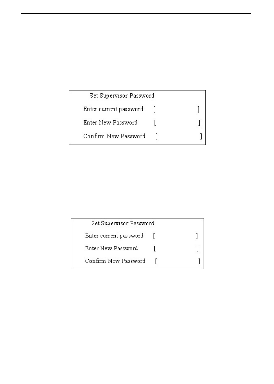
3. Press e.
After setting the password, the computer sets the User Password parameter to “Set”.
4. If desired, you can opt to enable the Password on boot parameter.
5. When you are done, press u to save the changes and exit the BIOS Setup Utility.
Removing a Password
Follow these steps:
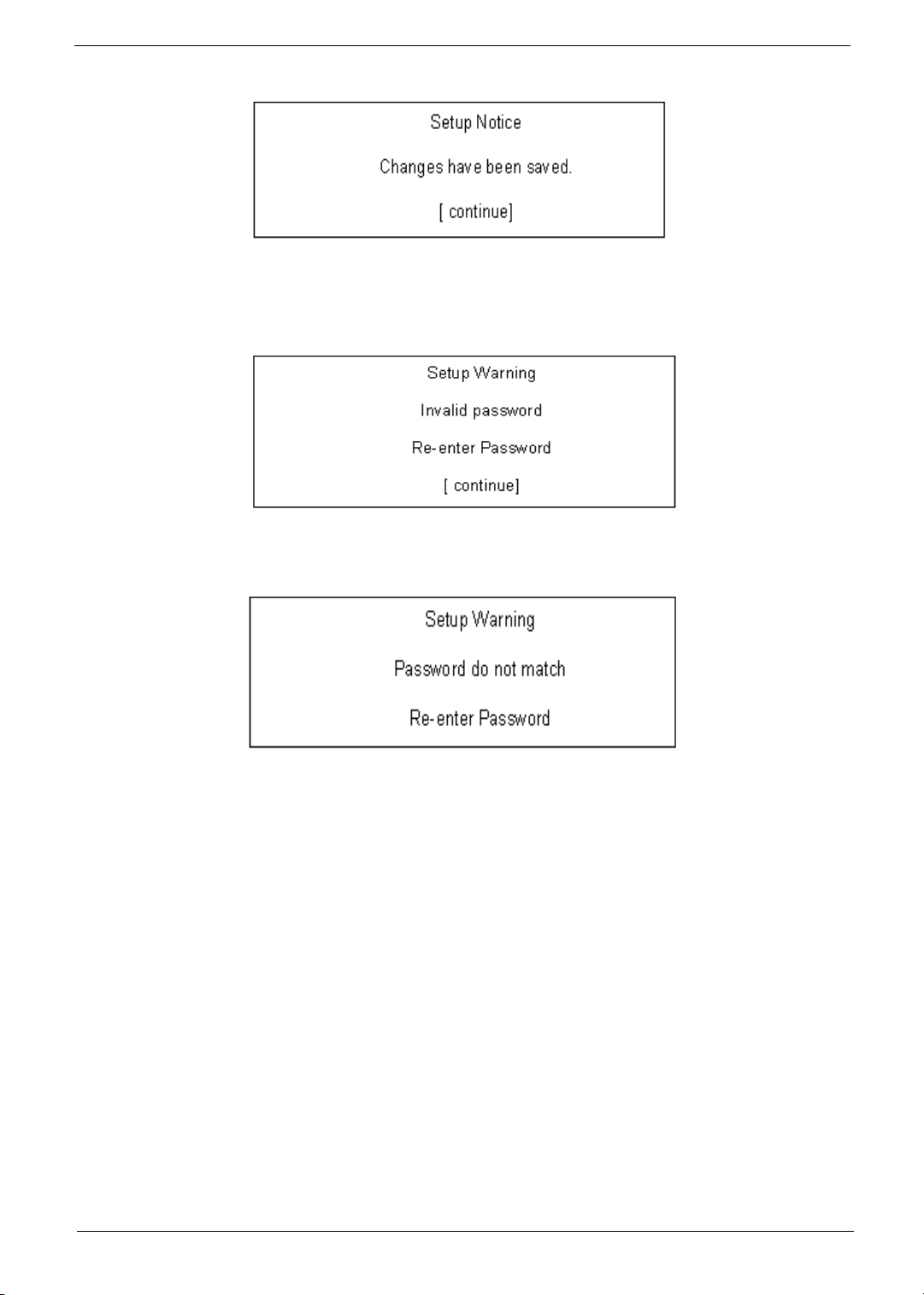
1. Use the w and y keys to highlight the Set Supervisor Password parameter and press the e key. The
Set Password box appears:
2. Type the current password in the Enter Current Password field and press e.
3. Press e twice without typing anything in the Enter New Password and Confirm New Password fields.
The computer then sets the Supervisor Password parameter to “Clear”.
4. When you have changed the settings, press u to save the changes and exit the BIOS Setup Utility.
Changing a Password
1. Use the w and y keys to highlight the Set Supervisor Password parameter and press the e key. The
Set Password box appears:
2. Type the current password in the Enter Current Password field and press e.
3. Type a password in the Enter New Password field. Retype the password in the Confirm New Password
field.
4. Press e. After setting the password, the computer sets the User Password parameter to “Set”.
5. If desired, you can enable the Password on boot parameter.
6. When you are done, press u to save the changes and exit the BIOS Setup Utility.
45 Chapter 2
Page 56
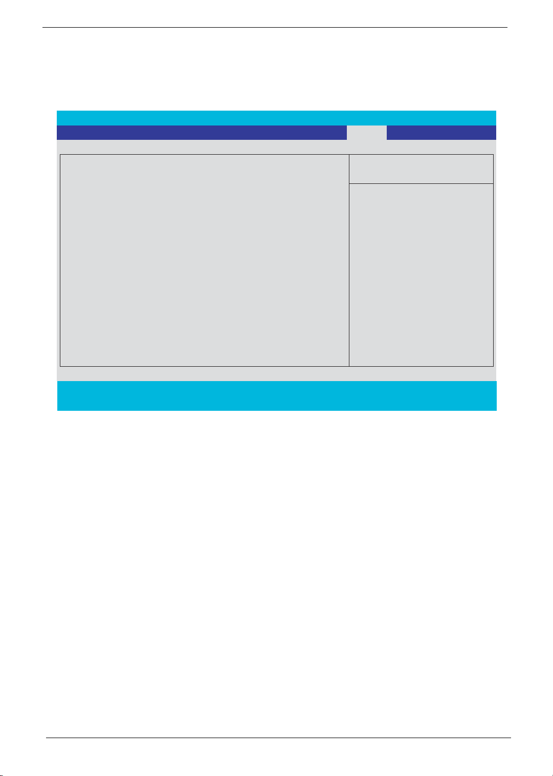
If the verification is OK, the screen will display as following.
The password setting is complete after the user presses u.
If the current password entered does not match the actual current password, the screen will show you the
Setup Warning.
If the new password and confirm new password strings do not match, the screen will display the following
message.
Chapter 2 46
Page 57
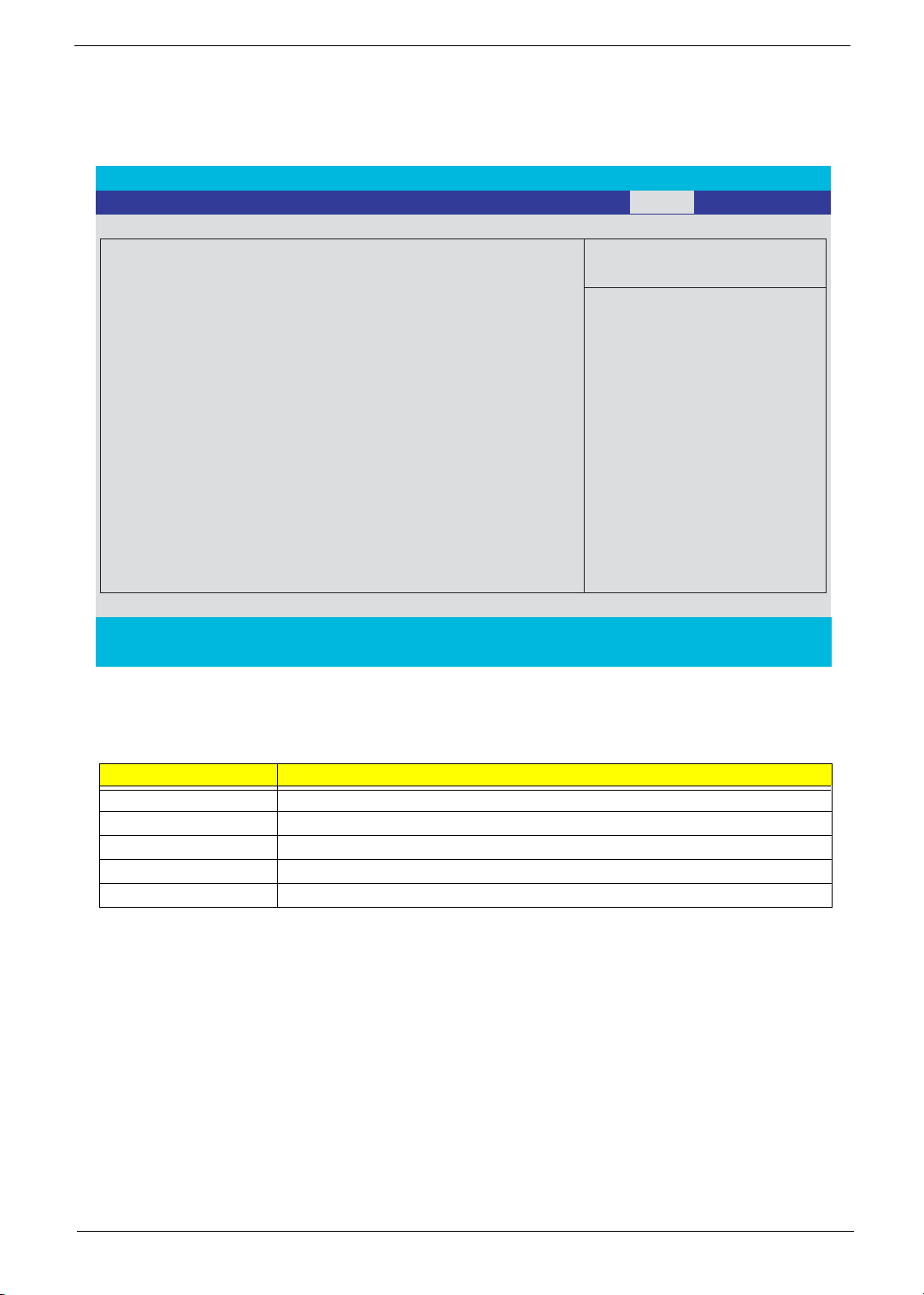
Boot
This menu allows the user to decide the order of boot devices to load the operating system. Bootable devices
includes the distette drive in module bay, the onboard hard disk drive and the CD-ROM in module bay.
PhoenixBIOS Setup Utility
Info. Main Advanced Security Exit
Boot
Item Specific Help
CD-ROM/DVD Drive
Floppy Devices
+Hard Drive
Network Boot
+ and - indicate device
categories. Use <Enter> to
expand/collapses.
Boot order is top-down using
only the top device in each
category.
Use <F6> and <F5> to move
highlighted item up and down.
F1 Help ↑↓ Select Item F5/F6 Change Values F9 Setup Defaults
Esc Exit ← → Select Menu Enter Select 4Sub-Menu F10 Save and Exit
47 Chapter 2
Page 58
Exit
The Exit screen contains parameters that help safeguard and protect your computer from unauthorized use.
PhoenixBIOS Setup Utility
Info. Main Advanced Security Boot
Exit Saving Changes
Exit Dicarding Changes
Load Setup Defaults
Discard Changes
Save Changes
Exit System Setup and save
your changes to CMOS.
Exit
Item Specific Help
F1 Help ↑↓ Select Item F5/F6 Change Values F9 Setup Defaults
Esc Exit ← → Select Menu Enter Select 4Sub-Menu F10 Save and Exit
The table below describes the parameters in this screen.
Parameter Description
Exit Saving Changes Exit System Setup and save your changes to CMOS.
Exit Discarding Changes Exit utility without saving setup data to CMOS.
Load Setup Default Load default values for all SETUP item.
Discard Changes Load previous values from CMOS for all SETUP items.
Save Changes Save Setup Data to CMOS.
Chapter 2 48
Page 59

BIOS Flash Utility
The BIOS flash memory update is required for the following conditions:
T New versions of system programs
T New features or options
T Restore a BIOS when it becomes corrupted.
Use the Phlash utility to update the system BIOS flash ROM.
NOTE: If you do not have a crisis recovery diskette at hand, then you should create a Crisis Recovery
Diskette before you use the Phlash utility.
NOTE: Do not install memory-related drivers (XMS, EMS, DPMI) when you use the Phlash.
NOTE: Please use the AC adaptor power supply when you run the Phlash utility. If the battery pack does not
contain enough power to finish BIOS flash, you may not boot the system because the BIOS is not
completely loaded.
Fellow the steps below to run the Phlash.
1. Prepare a bootable diskette.
2. Copy the Phlash utilities to the bootable diskette.
3. Then boot the system from the bootable diskette. The Phlash utility has auto-execution function.
49 Chapter 2
Page 60

Machine Disassembly and Replacement
This chapter contains step-by-step procedures on how to disassemble the notebook computer for
maintenance and troubleshooting.
To disassemble the computer, you need the following tools:
T Wrist grounding strap and conductive mat for preventing electrostatic discharge
T Small Philips screw driver
T Philips screwdriver
T Plastic flat head screw driver
T Twe ezer s
NOTE: The screws for the different components vary in size. During the disassembly process, group the
screws with the corresponding components to avoid mismatch when putting back the components.
When you remove the stripe cover, please be careful not to scrape the cover.
Chapter 3
Chapter 3 50
Page 61
General Information
Before You Begin
Before proceeding with the disassembly procedure, make sure that you do the following:
1. Turn off the power to the system and all peripherals.
2. Unplug the AC adapter and all power and signal cables from the system.
3. Remove the battery pack.
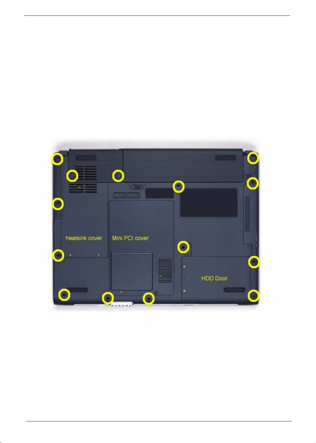
NOTE: The screws used to secure bottom case and upper case are more than one type. Please group same
type of screw together as you disassemble the system for service purpose. The image below is for your
reference. Please pay attention to the explanation below.
IO Bezel
Battery
The screws that secure heatsink cover, MIni PCI cover and HDD cover are with the covers. There is no need
to worry about mix them up. However, please notice that you have to group the screws on the following
locations together. There are twenty screws holding the bottom case to upper case but some screws are inside
the system. You may have to remove the HDD, the heatsink cover to see these screws. Mini PCI cover here
also called RAM/Wireless cover.
51 Chapter 3
Page 62
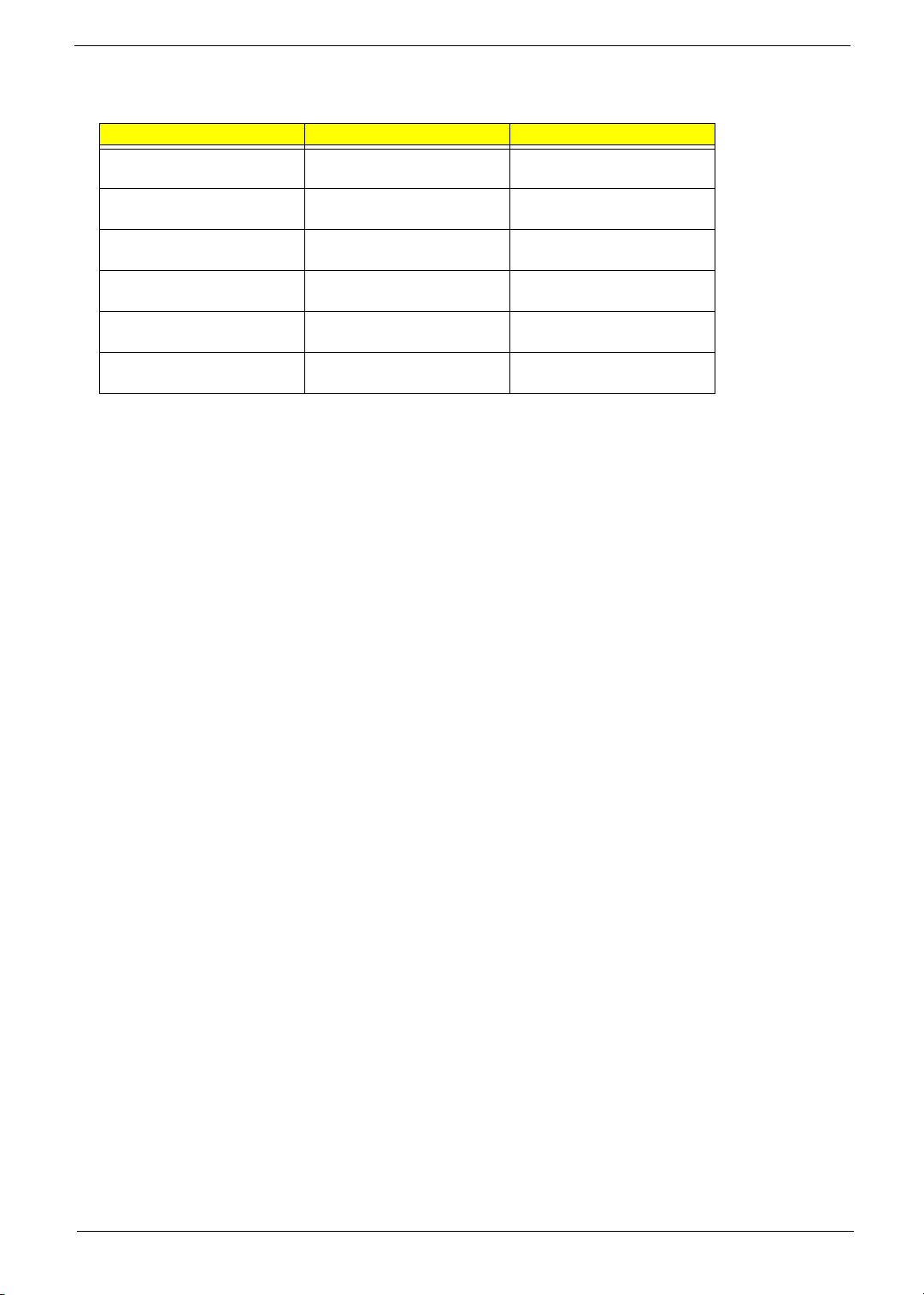
Screw Type Location Quantity
M2.5*6 Bottom case and IO bezel
(hightlight with yellow circle)
M2.5*6 Remove the IO bezel then
you will see.
M2.5*6 Remove the heatsink cover
then you will see.
M2.5*6 Remove the HDD cover then
you will see.
M2.5*3 Detach the HDD module
then you will see.
M2.5*3 Remove the battery then you
will see.
14
2
1
1
1
1
Chapter 3 52
Page 63
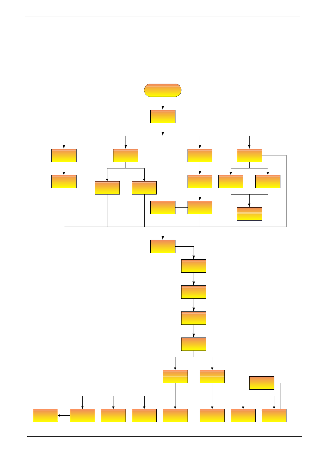
Disassembly Procedure Flowchart
The flowchart on the succeeding page gives you a graphic representation on the entire disassembly sequence
and instructs you on the components that need to be removed during servicing. For example, if you want to
remove the system board, you must first remove the keyboard, then disassemble the inside assembly frame in
that order.
Start
Battery
K*2
HDD Cover ODD Module
HDD Module
Wireless LAN
Card
E*2
RAM/Wireless
Cover
Memory
CPU
*3
Middle Cover
LCD Module
Switch Board
*2
IO Bezel
Heatsink
Cover
Thermal
Module
*2
Keyboard
(right and left hinges)
*2
*2
*2
ODD
Connector
Board
ODD Drive
*4
*6
ODD Holder
*5
*18
Lower and
Upper Case
Assembly
Upper Case
Assembly
Touchpad
Bracket
Bluetooth
Module
Touchpad
Touchpad
Board
VGA Heatsink
*3
*2 screw nuts
Main Board
*2
3-in-1 Cover Speaker Set Modem Board
*4
Lower Case
Assembly
*2
53 Chapter 3
Page 64
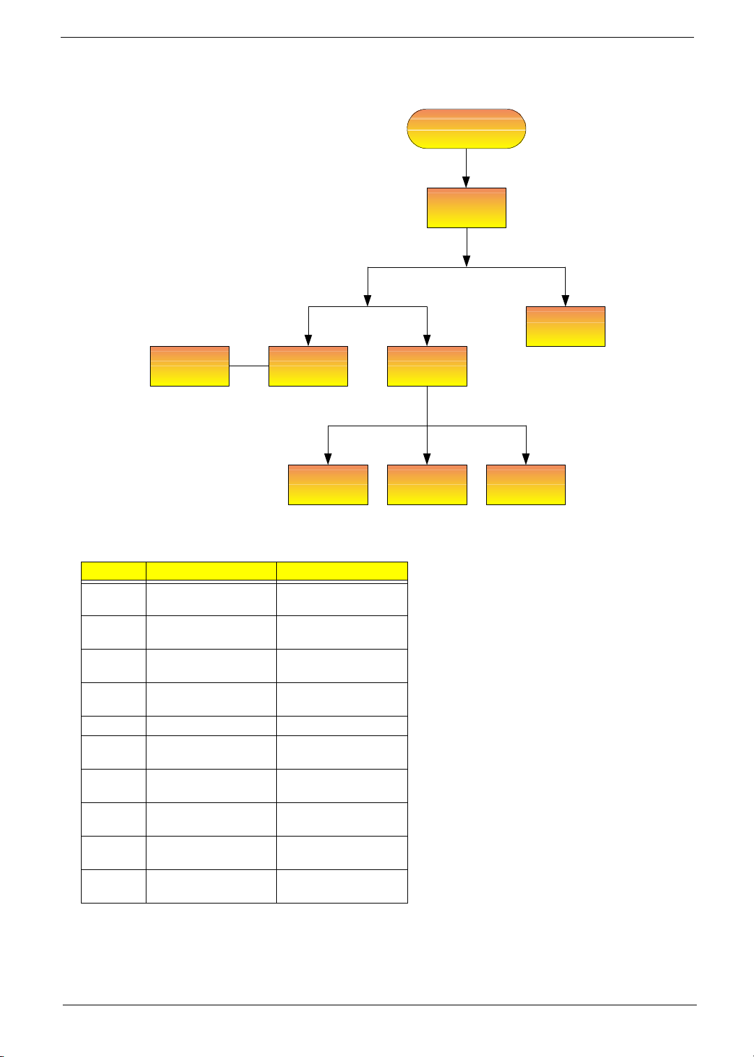
*6 hinges
*2 brackets
LCD Module
4 screw pads
M*4
LCD Bezel
LCD Inverter
Antenna set
Screw List
Item Description
SCREW M2.0X3.0-I-NINYLOK
SCREW I2.5*3MBNIH(M2.5L3)
SCREW M2.5*4L-BZNNYLOK
SCREW M2.0X5-I-NINYLOK
SCREW MM25060IL69
SCREW M2.0*5I(NI)(NYLOK)
SCREW M2.0X2.5-I-NINYLOK
SCREW I2*3M-NIHY
(M2L3)
SCREW M1.7*3.0-I
(BK)
SCREW I3*3.5MNIH(M3L3.5)
LCD Cover
LCD LCD Cable LCD Brackets
86.A03V7.012
86.T25V7.012
86.A03V7.006
86.T23V7.006
86.A08V7.004
86.T23V7.010
86.A03V7.007
86.T25V7.008
86.T50V7.001
86.A03V7.011
LCD
Assembly
*4
Chapter 3 54
Page 65
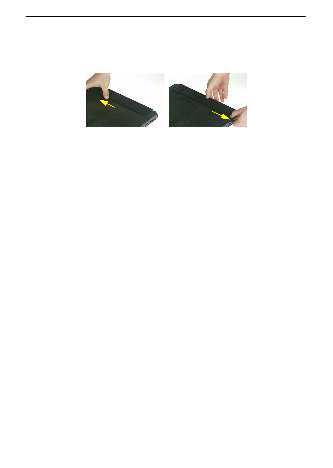
Removing the Battery Pack
1. Unlock the battery lock.
2. Slide the battery latch as shown then remove the battery pack.
55 Chapter 3
Page 66
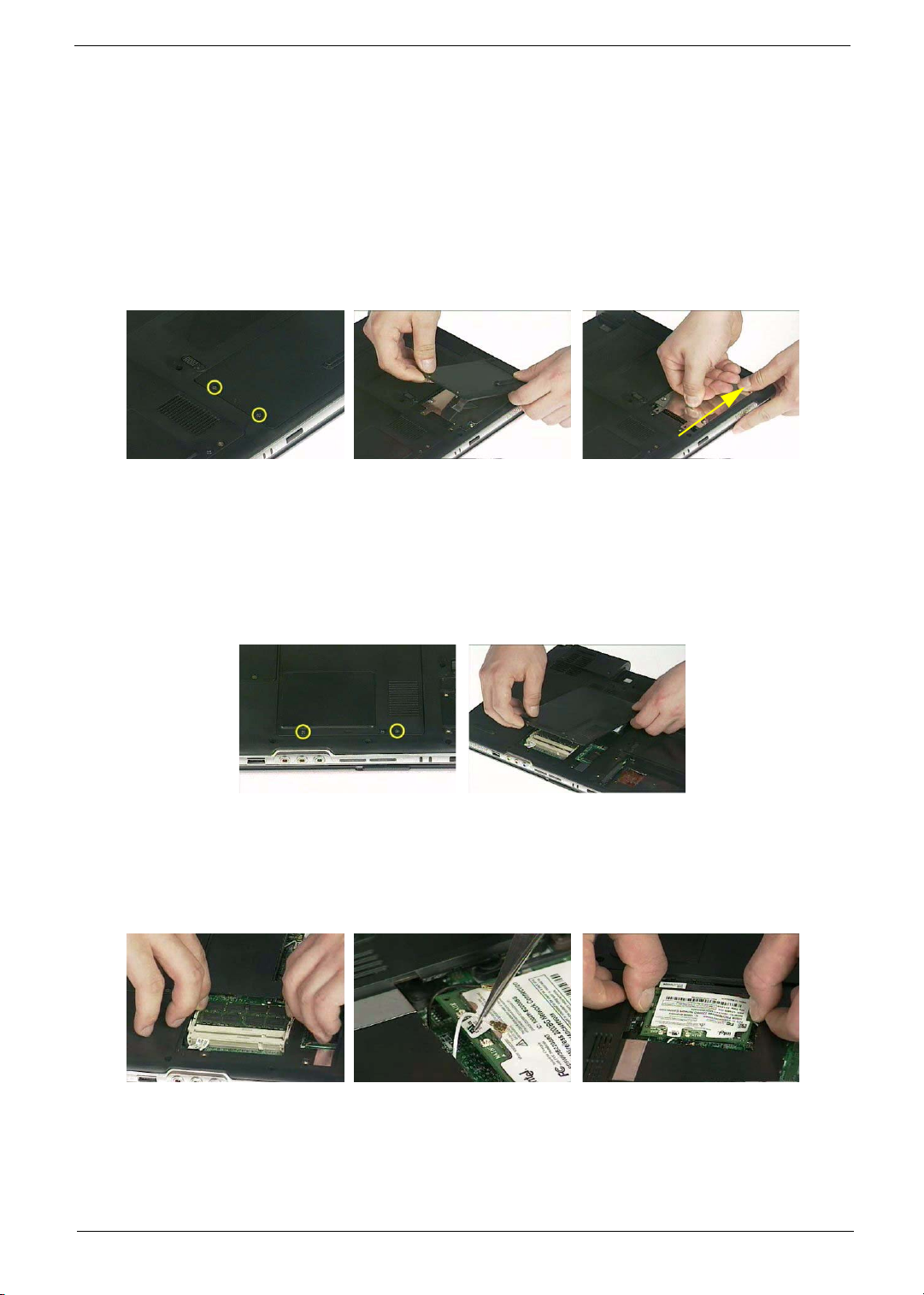
Removing the HDD Module/the Memory and the Wireless LAN Card/
the Thermal Module and the CPU/ODD Module and LCD Module
Removing the HDD Module
1. Remove the two screws holding the HDD cover.
2. Remove the HDD cover.
3. Detach the HDD module then remove it.
Removing the Memory and the Wireless LAN Card
1. Remove the two screws that secure the RAM/Wireless cover.
2. Remove the RAM/Wireless cover.
3. Pop up the memory then remove it.
4. Disconnect the auxiliary and the main wireless antennae.
5. Pop the wireless LAN card then remove it.
.
Removing the Thermal Module and CPU
1. Remove the two screws holding the IO bezel.
Chapter 3 56
Page 67
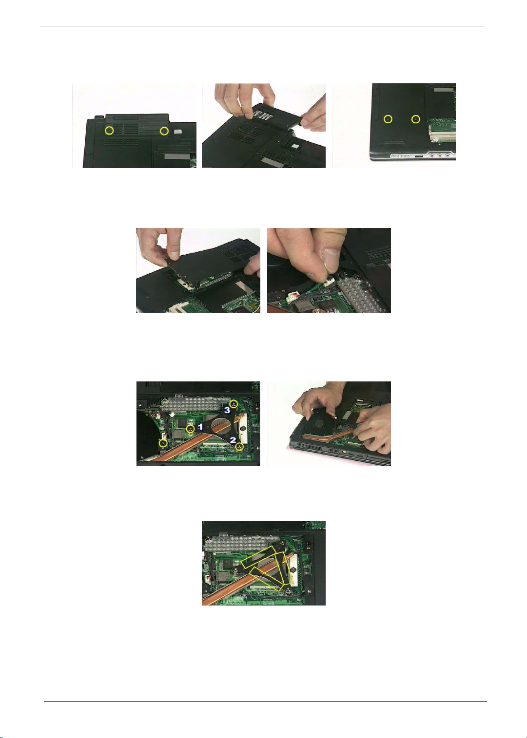
2. Then remove the IO bezel.
3. Remove the two screws that secure the heatsink cover.
4. Remove the heatsink cover from the main unit.
5. Disconnect the fan cable.
6. Remove the four screws that secure the thermal module.
7. Pull the thermal module outwards then remove it.
NOTE: The edge of the thermal module as shown is very sharp. Be very careful as you remove the thermal
module.
8. Use a flat-bladed screwdriver to release the CPU lock.
9. Remove the CPU from the socket carefully.
57 Chapter 3
Page 68
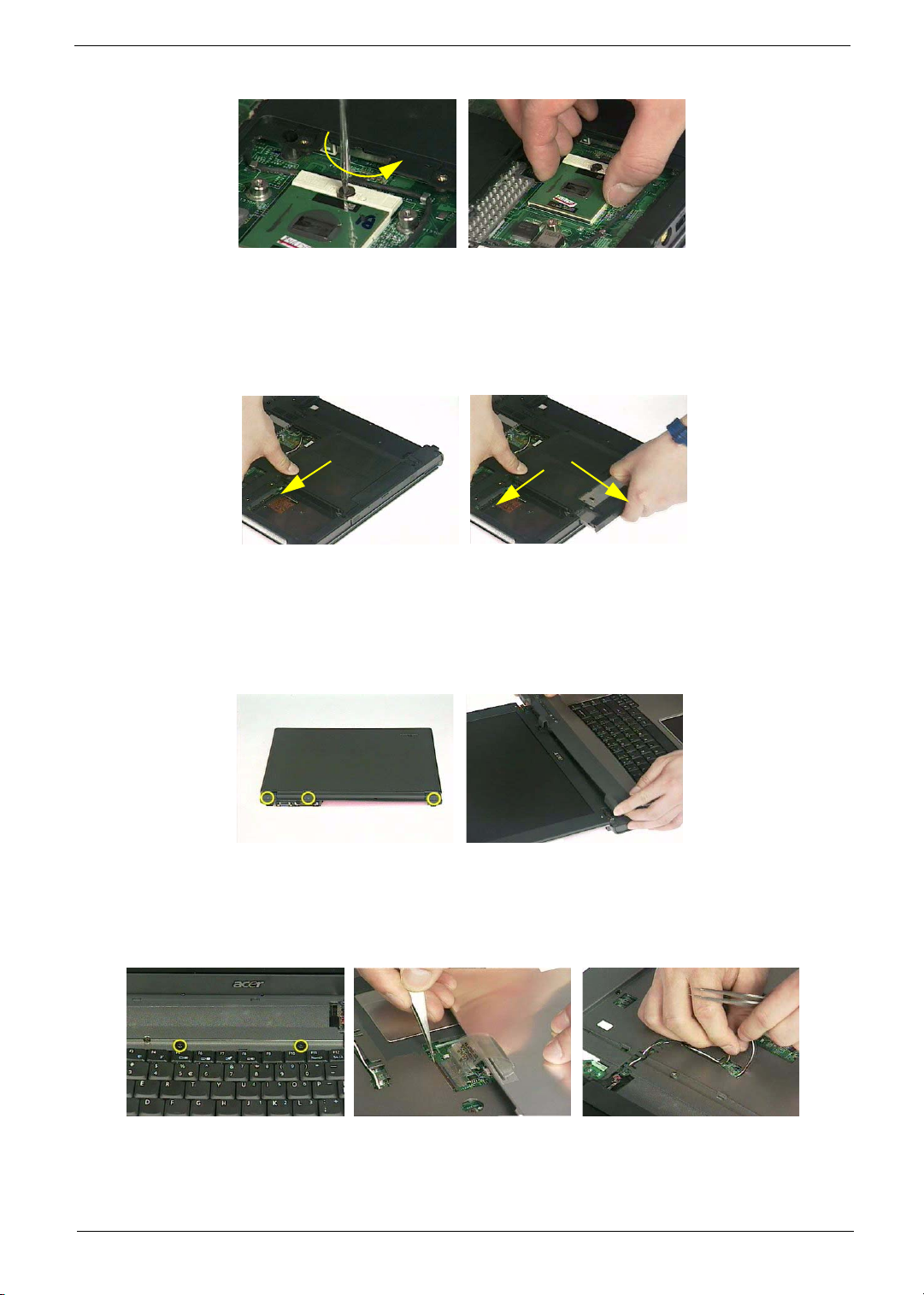
Removing the ODD Module
1. Release the ODD latch.
2. Remove the ODD module from the main unit.
.
Removing the LCD Module
1. Remove the three screws holding the keyboard cover.
2. Open the LCD module as the picture shown then detach the keyboard cover from the main unit.
.
3. Remove the two screws that secure the keyboard as shown.
4. Turn over the keyboard as shown and disconnect the keyboard cable then remove the keyboard.
5. Pull out the antenna set with a tweezers then take out the antenna set from the main unit.
.
6. Disconnect the LCD coaxial cable.
7. Remove the four screws holding the right and the left hinge. Two on each side.
Chapter 3 58
Page 69
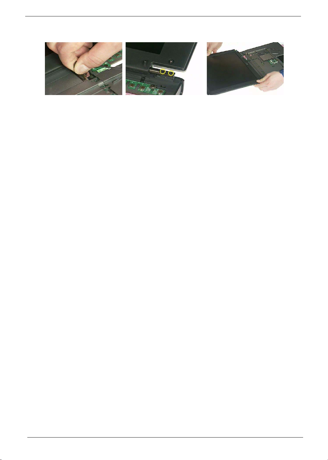
8. Then detach the LCD module from the main unit.
.
59 Chapter 3
Page 70
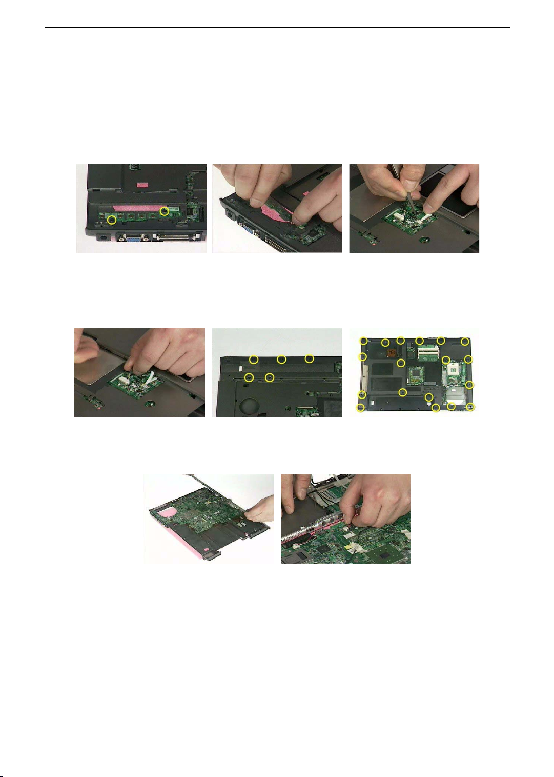
Disassembling the Main Unit
Separate the Main Unit Into the Upper and the Lower Case Assembly
1. Remove the two screws holding the switch board.
2. Remove the switch board.
3. Disconnect the touchpad FFC from the main board.
4. Disconnect the bluetooth cable.
5. Remove the five screws that secure the upper case.
6. Remove the eighteen screws on the bottom as shown.
7. Detach the upper case assembly and place it next to the lower case assembly.
8. Disconnect the microphone cable then remove the upper case assembly.
Disassembling the Upper Case Assembly
1. Disconnect the touchpad board to touchpad FFC.
2. Disconnect the touchpad board to main board FFC.
3. Then detach the touchpad board to main board FFC from the touchpad board.
Chapter 3 60
Page 71
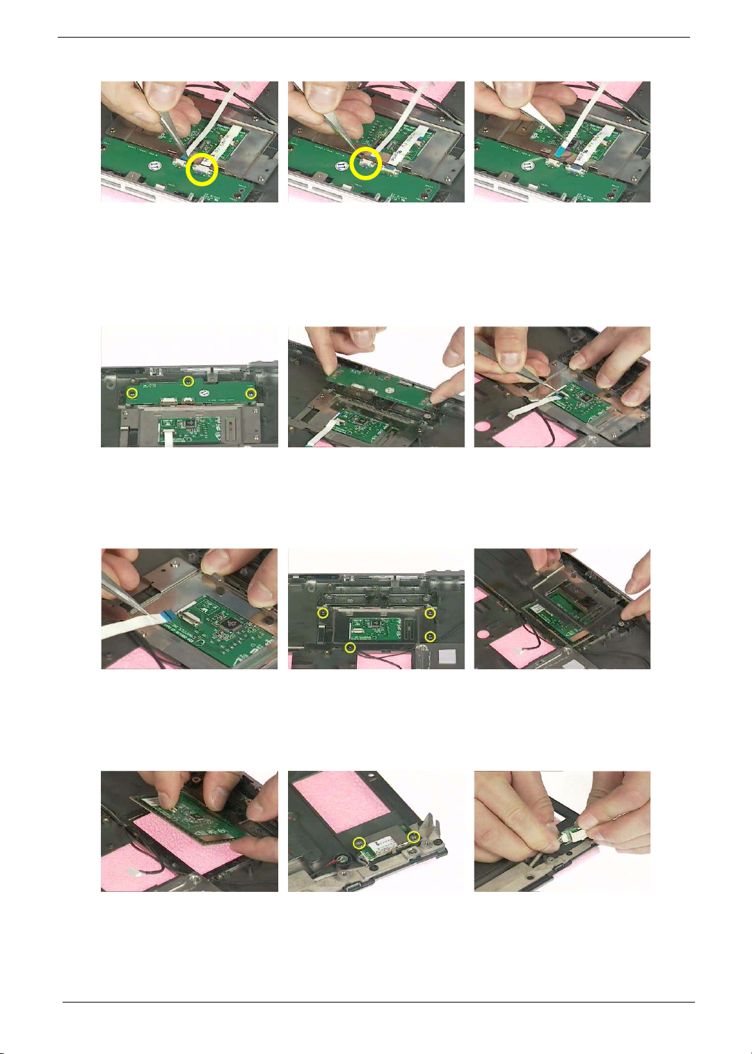
4. Remove the three screws that secure the touchpad board.
5. Remove the touchpad board from the upper case.
6. Disconnect the touchpad board to touchpad FFC.
7. Remove the touchpad board to touchpad FFC from the uppwer case assembly.
8. Remove the four screws holding the touchpad bracket.
9. Detach the touchpad bracket from the upper case assembly.
10. Remove the touchpad from the upper case.
11. Remove the two screws that secure the bluetooth module.
12. Disconnect the bluetooth module then remove it.
Disassembling the Lower Case Assembly
61 Chapter 3
Page 72
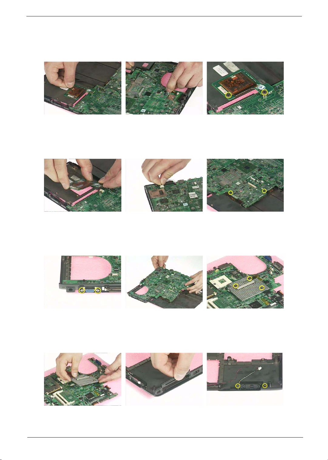
1. Disconnect the MDC cable from the modem board.
2. Detach the MDC cable from the main board.
3. Remove the two screws holding the modem board.
4. Remove the modem board from the lower case.
5. Disconnect the speaker cable from the main board.
6. Remove the two screws that secure the main board.
7. Remove the two screw nuts as shown.
8. The you can detach the main board from the upper case.
9. Remove the three screws that secure the VGA heatsink.
10. Remove the VGA heatsink from the main board as shown.
11. Remove the three in one cover from the lower case.
12. Remove the two screws that secure the speaker set on one side.
13. Then remove another two screws holding the speaker set on the other side.
14. Then take out the speaker set from the lower case.
Chapter 3 62
Page 73
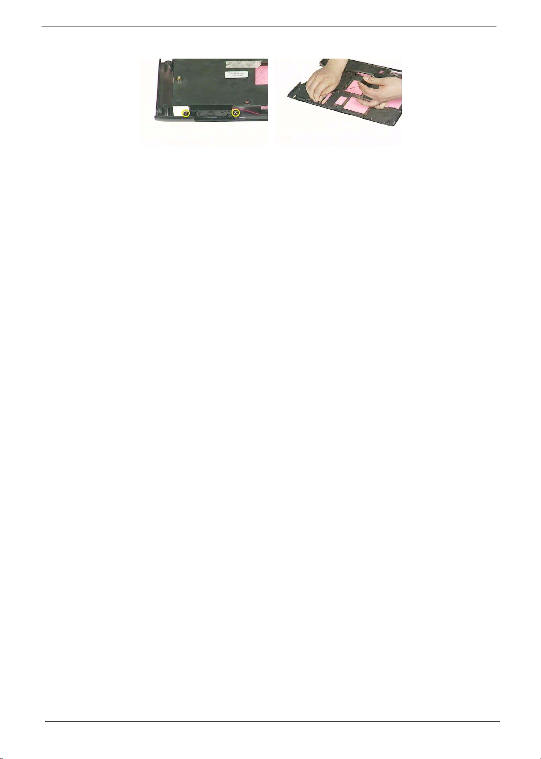
63 Chapter 3
Page 74
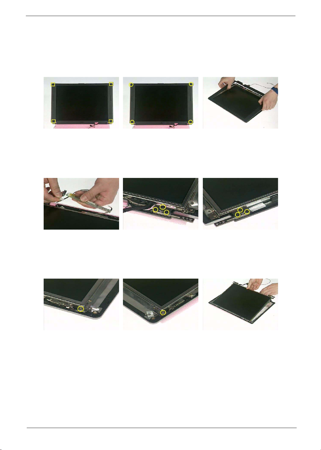
Disassembling the LCD Module
1. Remove the four screw caps as shown.
2. Remove the four screws holding the LCD bezel.
3. Then detach the LCD bezel from the LCD module.
4. Disconnect the inverter board then remove it.
5. Remove the three screws holding the right hinge.
6. Then remove the three screws that secure the left hinge.
7. Remove one screw that secure the LCD bracket.
8. Remove another screw holding the LCD bracket on the other side.
9. Then detach the LCD panel from the LCD cover carefully.
.
10. Remove the two screws holding the right bracket.
11. Then remove the right bracket.
12. Remove another two screws that tighten the left bracket.
Chapter 3 64
Page 75
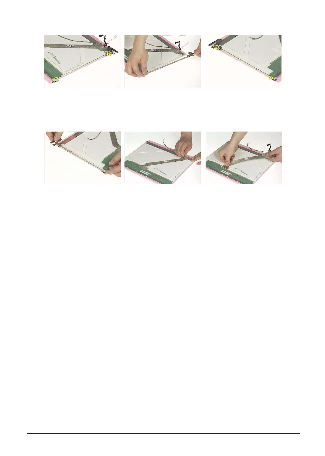
13. Remove the left bracket as the picture shows.
14. Tear off the tape fastening the LCD cable.
15. Tear off the the LCD cable fastening the LCD cable, then remove it..
65 Chapter 3
Page 76
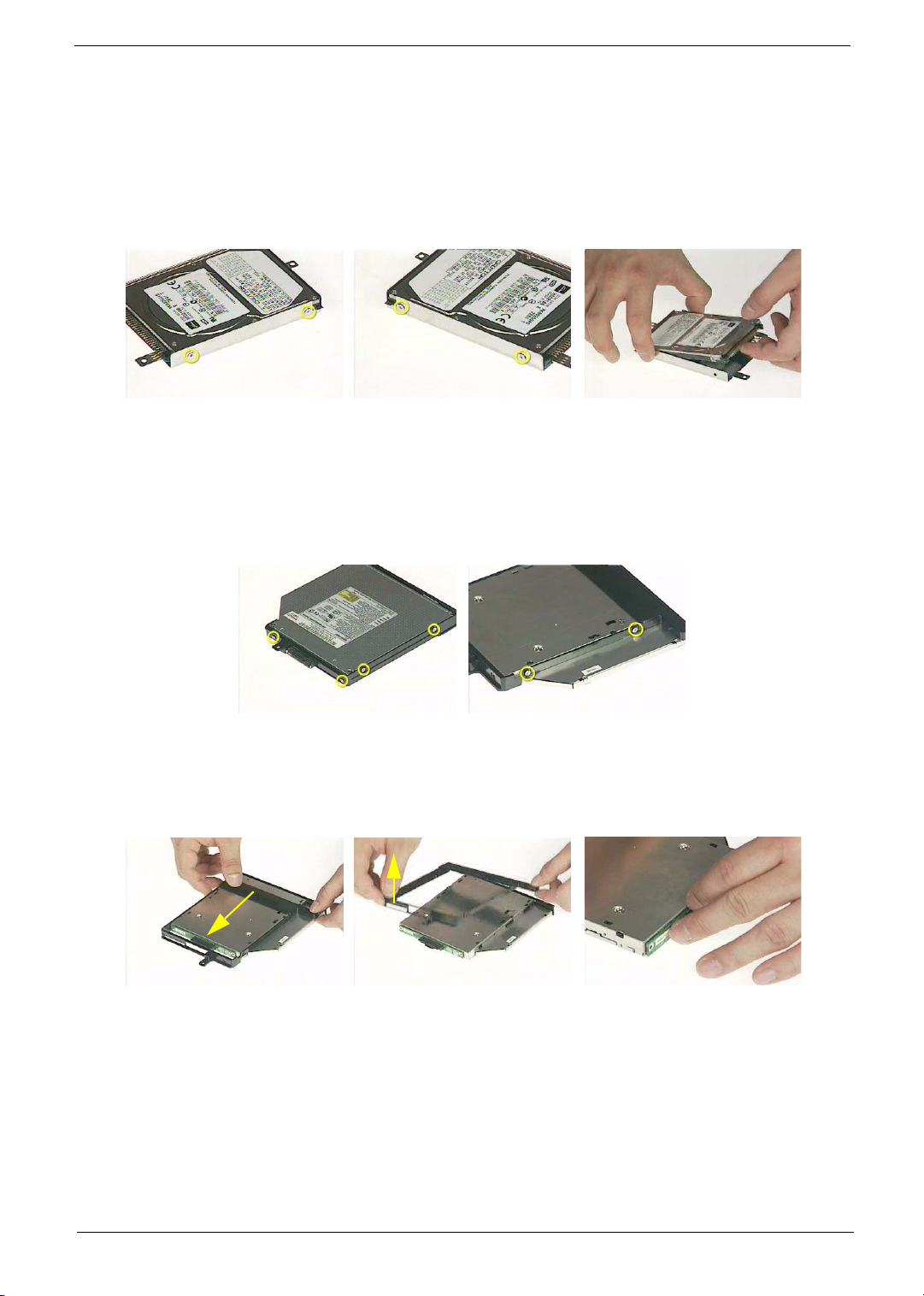
Disassembling the External Modules
Disassembling the HDD Module
1. Remove the two screws holding the HDD bracket on one side.
2. Remove another two screws holding the HDD bracket on the other side.
3. Then take the hard disc drive out from the HDD bracket.
Disassembling the Optical Drive Module
1. Remove the four screws as the picture shows.
2. Remove the two screws that secure the optical disc drive and the ODD holder.
3. Push the ODD holder as shown.
4. Detach the ODD holder.
5. Disconnect the ODD connector board then remove it.
Chapter 3 66
Page 77

67 Chapter 3
Page 78
Troubleshooting
Use the following procedure as a guide for computer problems.
NOTE: The diagnostic tests are intended to test only Acer products. Non-Acer products, prototype cards, or
modified options can give false errors and invalid system responses.
1. Obtain the failing symptoms in as much detail as possible.
2. Verify the symptoms by attempting to re-create the failure by running the diagnostic test or by repeating
the same operation.
3. Use the following table with the verified symptom to determine which page to go to.
Symptoms (Verified) Go To
Power failure. (The power indicator does not go
on or stay on.)
POST does not complete. No beep or error
codes are indicated.
POST detects an error and displayed messages
on screen.
Other symptoms (i.e. LCD display problems or
others).
Symptoms cannot be re-created (intermittent
problems).
“Power System Check” on page 70.
“Power-On Self-Test (POST) Error Message” on
page 73
“Undetermined Problems” on page 82
“Error Message List” on page 74
“Power-On Self-Test (POST) Error Message” on
page 73
Use the customer-reported symptoms and go to
“Power-On Self-Test (POST) Error Message” on
page 73
“Intermittent Problems” on page 81
“Undetermined Problems” on page 82
Chapter 4
Chapter 4 68
Page 79

System Check Procedures
External Diskette Drive Check
Do the following to isolate the problem to a controller, driver, or diskette. A write-enabled, diagnostic diskette is
required.
NOTE: Make sure that the diskette does not have more than one label attached to it. Multiple labels can cause
damage to the drive or cause the drive to fail.
Do the following to select the test device.
1. Boot from the diagnostics diskette and start the diagnostics program.
2. See if FDD Test is passed as the program runs to FDD Test.
3. Follow the instructions in the message window.
If an error occurs with the internal diskette drive, reconnect the diskette connector on the system board.
If the error still remains:
1. Reconnect the external diskette drive/DVD-ROM module.
2. Replace the external diskette drive/CD-ROM module.
3. Replace the main board.
External CD-ROM Drive Check
Do the following to isolate the problem to a controller, drive, or CD-ROM. Make sure that the CD-ROM does
not have any label attached to it. The label can cause damage to the drive or can cause the drive to fail.
Do the following to select the test device:
1. Boot from the diagnostics diskette and start the diagnostics program.
2. See if CD-ROM Test is passed when the program runs to CD-ROM Test.
3. Follow the instructions in the message window.
If an error occurs, reconnect the connector on the System board. If the error still remains:
1. Reconnect the external diskette drive/CD-ROM module.
2. Replace the external diskette drive/CD-ROM module.
3. Replace the main board.
Keyboard or Auxiliary Input Device Check
Remove the external keyboard if the internal keyboard is to be tested.
If the internal keyboard does not work or an unexpected character appears, make sure that the flexible cable
extending from the keyboard is correctly seated in the connector on the system board.
If the keyboard cable connection is correct, run the Keyboard Test.
If the tests detect a keyboard problem, do the following one at a time to correct the problem. Do not replace a
non-defective FRU:
1. Reconnect the keyboard cables.
2. Replace the keyboard.
3. Replace the main board.
The following auxiliary input devices are supported by this computer:
T Numeric keypad
T External keyboard
69 Chapter 4
Page 80

If any of these devices do not work, reconnect the cable connector and repeat the failing operation.
Memory check
Memory errors might stop system operations, show error messages on the screen, or hang the system.
1. Boot from the diagnostics diskette and start the doagmpstotics program (please refer to main board.
2. Go to the diagnostic memory in the test items.
3. Press F2 in the test items.
4. Follow the instructions in the message window.
NOTE: Make sure that the DIMM is fully installed into the connector. A loose connection can cause an error.
Power System Check
To verify the symptom of the problem, power on the computer using each of the following power sources:
1. Remove the battery pack.
2. Connect the power adapter and check that power is supplied.
3. Disconnect the power adapter and install the charged battery pack; then check that power is supplied by
the battery pack.
If you suspect a power problem, see the appropriate power supply check in the following list:
T “Check the Power Adapter” on page 71
T “Check the Battery Pack” on page 72
Chapter 4 70
Page 81

Check the Power Adapter
Unplug the power adapter cable from the computer and measure the output voltage at the plug of the power
adapter cable. See the following figure
Pin 1: +19 to +20.5V
Pin 2: 0V, Ground
1. If the voltage is not correct, replace the power adapter.
2. If the voltage is within the range, do the following:
T Replace the System board.
T If the problem is not corrected, see “Undetermined Problems” on page 82.
T If the voltage is not correct, go to the next step.
NOTE: An audible noise from the power adapter does not always indicate a defect.
3. If the power-on indicator does not light up, check the power cord of the power adapter for correct
continuity and installation.
4. If the operational charge does not work, see “Check the Battery Pack” on page 72.
71 Chapter 4
Page 82
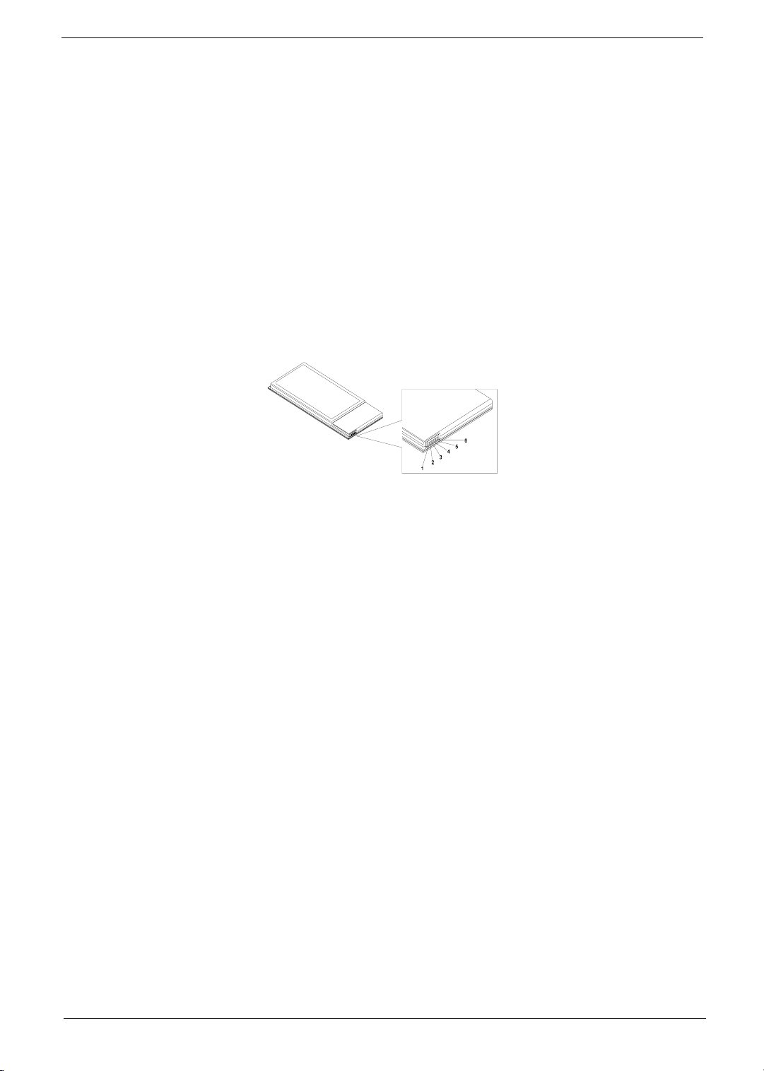
Check the Battery Pack
To check the battery pack, do the following:
From Software:
1. Check out the Power Management in control Panel
2. In Power Meter, confirm that if the parameters shown in the screen for Current Power Source and Total
Battery Power Remaining are correct.
3. Repeat the steps 1 and 2, for both battery and adapter.
4. This helps you identify first the problem is on recharging or discharging.
From Hardware:
1. Power off the computer.
2. Remove the battery pack and measure the voltage between battery terminals 1(+) and 6(ground). See the
following figure
3. If the voltage is still less than 7.5 Vdc after recharging, replace the battery.
To check the battery charge operation, use a discharged battery pack or a battery pack that has less than 50%
of the total power remaining when installed in the computer.
If the battery status indicator does not light up, remove the battery pack and let it return to room temperature.
Re-install the battery pack.
If the charge indicator still does not light up, replace the battery pack. If the charge indicator still does not light
up, replace the DC/DC charger board.
Touch pa d C h eck
If the touchpad doesn’t work, do the following actions one at a time to correct the problem. Do not replace a
non-defective FRU:
1. Reconnect the touchpad cables.
2. Replace the touchpad.
3. Replace the system board.
After you use the touchpad, the pointer drifts on the screen for a short time. This self-acting pointer movement
can occur when a slight, steady pressure is applied to the touchpad pointer. This symptom is not a hardware
problem. No service actions are necessary if the pointer movement stops in a short period of time.
Chapter 4 72
Page 83

Power-On Self-Test (POST) Error Message
The POST error message index lists the error message and their possible causes. The most likely cause is
listed first.
NOTE: Perform the FRU replacement or actions in the sequence shown in FRU/Action column, if the FRU
replacement does not solve the problem, put the original part back in the computer. Do not replace a
non-defective FRU.
This index can also help you determine the next possible FRU to be replaced when servicing a computer.
If the symptom is not listed, see “Undetermined Problems” on page 82.
The following lists the error messages that the BIOS displays on the screen and the error symptoms classified
by function.
NOTE: Most of the error messages occur during POST. Some of them display information about a hardware
device, e.g., the amount of memory installed. Others may indicate a problem with a device, such as the
way it has been configured.
NOTE: If the system fails after you make changes in the BIOS Setup Utility menus, reset the computer, enter
Setup and install Setup defaults or correct the error.
73 Chapter 4
Page 84
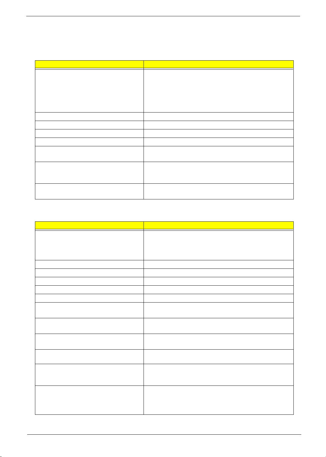
Index of Error Messages
Error Code List
Error Codes Error Messages
006 Equipment Configuration Error
Causes:
1. CPU BIOS Update Code Mismatch
2. IDE Primary Channel Master Drive Error
(THe causes will be shown before “Equipment Configuration
Error”)
010 Memory Error at xxxx:xxxx:xxxxh (R:xxxxh, W:xxxxh)
070 Real Time Clock Error
071 CMOS Battery Bad
072 CMOS Checksum Error
110 System disabled.
Incorrect password is specified.
<No error code> Battery critical LOW
In this situation BIOS will issue 4 short beeps then shut down
system, no message will show.
<No error code> Thermal critical High
In this situation BIOS will shut down system, not show message.
Error Message List
Error Messages FRU/Action in Sequence
Failure Fixed Disk Reconnect hard disk drive connector.
“Load Default Settings” in BIOS Setup Utility.
Hard disk drive
System board
Stuck Key see “Keyboard or Auxiliary Input Device Check” on page 69.
Keyboard error see “Keyboard or Auxiliary Input Device Check” on page 69.
Keyboard Controller Failed see “Keyboard or Auxiliary Input Device Check” on page 69.
Keyboard locked - Unlock key switch Unlock external keyboard
Monitor type does not match CMOS - Run Setup Run “Load Default Settings” in BIOS Setup Utility.
Shadow RAM Failed at offset: nnnn BIOS ROM
System board
System RAM Failed at offset: nnnn DIMM
System board
Extended RAM Failed at offset: nnnn DIMM
System board
System battery is dead - Replace and run Setup Replace RTC battery and Run BIOS Setup Utility to reconfigure
System CMOS checksum bad - Default
configuration used
System timer error RTC battery
system time, then reboot system.
RTC battery
Run BIOS Setup Utility to reconfigure system time, then reboot
system.
Run BIOS Setup Utility to reconfigure system time, then reboot
system.
System board
Chapter 4 74
Page 85
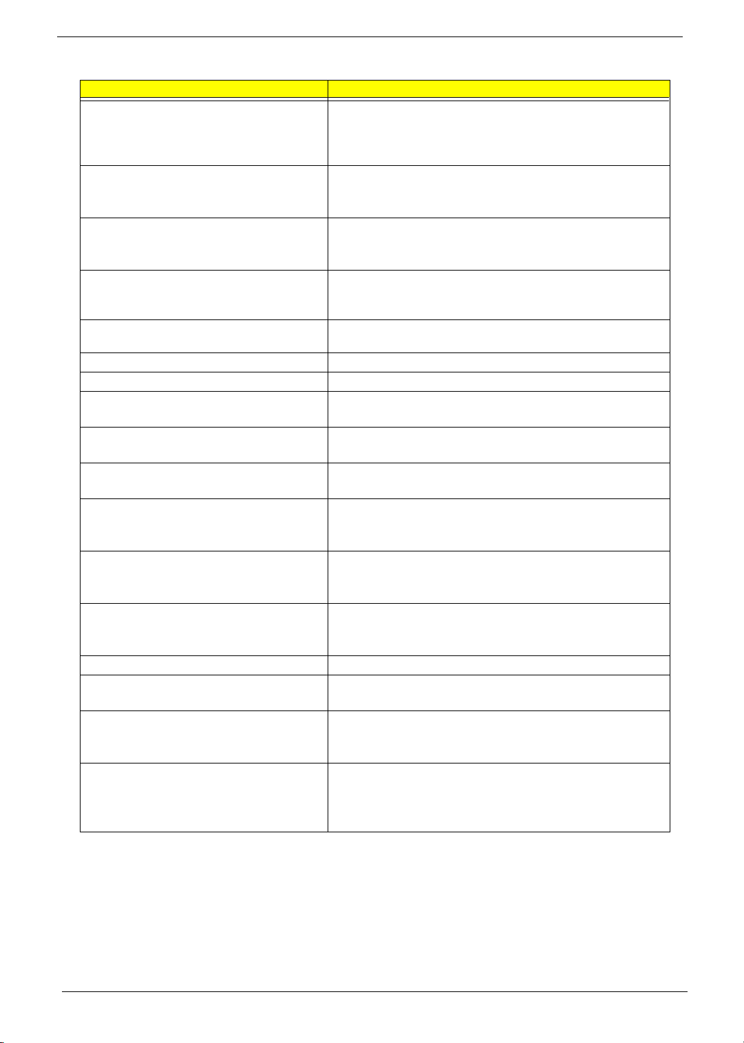
Error Message List
Error Messages FRU/Action in Sequence
Real time clock error RTC battery
Run BIOS Setup Utility to reconfigure system time, then reboot
system.
System board
Previous boot incomplete - Default configuration
used
Memory size found by POST differed from
CMOS
Diskette drive A error Check the drive is defined with the proper diskette type in BIOS
Incorrect Drive A type - run SETUP Check the drive is defined with the proper diskette type in BIOS
System cache error - Cache disabled System board
CPU ID: System board
DMA Test Failed DIMM
Software NMI Failed DIMM
Fail-Safe Timer NMI Failed DIMM
Device Address Conflict Run “Load Default Settings” in BIOS Setup Utility.
Allocation Error for device Run “Load Default Settings” in BIOS Setup Utility.
Failing Bits: nnnn DIMM
Fixed Disk n None
Invalid System Configuration Data BIOS ROM
I/O device IRQ conflict Run “Load Default Settings” in BIOS Setup Utility.
Operating system not found Enter Setup and see if fixed disk and drive A: are properly identified.
Run “Load Default Settings” in BIOS Setup Utility.
RTC battery
System board
Run “Load Default Settings” in BIOS Setup Utility.
DIMM
System board
Setup Utility
See “External Diskette Drive Check” on page 69.
Setup Utility
System board
System board
System board
RTC battery
System board
RTC battery
System board
BIOS ROM
System board
System board
RTC battery
System board
Diskette drive
Hard disk drive
System board
75 Chapter 4
Page 86
Error Message List
No beep Error Messages FRU/Action in Sequence
No beep, power-on indicator turns off and LCD is
blank.
No beep, power-on indicator turns on and LCD is
blank.
No beep, power-on indicator turns on and LCD is
blank. But you can see POST on an external
CRT.
No beep, power-on indicator turns on and a
blinking cursor shown on LCD during POST.
No beep during POST but system runs correctly. Speaker
Power source (battery pack and power adapter). See “Power
System Check” on page 70.
Ensure every connector is connected tightly and correctly.
Reconnect the DIMM.
LED board.
System board.
Power source (battery pack and power adapter). See “Power
System Check” on page 70.
Reconnect the LCD connector
Hard disk drive
LCD inverter ID
LCD cable
LCD Inverter
LCD
System board
Reconnect the LCD connectors.
LCD inverter ID
LCD cable
LCD inverter
LCD
System board
Ensure every connector is connected tightly and correctly.
System board
System board
Chapter 4 76
Page 87
POST Code
Code Beeps For Boot Block in Flash ROM
E0h Initialize the chipset
E1h Initialize the bridge
E2h Initialize the CPU
E3h Initialize the system timer
E4h Initialize system I/O
E5h Check force recovery boot
E6h Checksum BIOS ROM
E7h Go to BIOS
E8h Set Huge Segment
E9h Initialize Multi Processor
EAh Initialize OEM special code
EBh Initialize PIC and DMA
ECh Initialize Memory type
EDh Initialize Memory size
EEh Shadow Boot Block
EFh System memory test
F0h Initialize interrupt vectors
F1h Initialize Run Time Clock
F2h Initialize video
F3h Initialize System Management Mode
F4h 1 Output one beep before boot
F5h Boot to Mini DOS
F6h Clear Huge Segment
F7h Boot to Full DOS
77 Chapter 4
Page 88
Index of Symptom-to-FRU Error Message
LCD-Related Symptoms
Symptom / Error Action in Sequence
LCD backlight doesn't work
LCD is too dark
LCD brightness cannot be adjusted
LCD contrast cannot be adjusted
Unreadable LCD screen
Missing pels in characters
Abnormal screen
Wrong color displayed
LCD has extra horizontal or vertical lines
displayed.
Enter BIOS Utility to execute “Load Setup Default Settings”, then
reboot system.
Reconnect the LCD connectors.
Keyboard (if contrast and brightness function key doesn't work).
LCD inverter ID
LCD cable
LCD inverter
LCD
System board
Reconnect the LCD connector
LCD inverter ID
LCD cable
LCD inverter
LCD
System board
LCD inverter ID
LCD inverter
LCD cable
LCD
System board
Indicator-Related Symptoms
Symptom / Error Action in Sequence
Indicator incorrectly remains off or on, but system
runs correctly
Reconnect the inverter board
Inverter board
System board
Power-Related Symptoms
Symptom / Error Action in Sequence
Power shuts down during operation Power source (battery pack and power adapter). See “Power
The system doesn’t power-on. Power source (battery pack and power adapter). See “Power
The system doesn’t power-off. Power source (battery pack and power adapter). See “Power
System Check” on page 70.
Battery pack
Power adapter
Hard drive & battery connection board
System board
System Check” on page 70.
Battery pack
Power adapter
Hard drive & battery connection board
System board
System Check” on page 70.
Hold and press the power switch for more than 4 seconds.
System board
Chapter 4 78
Page 89
Power-Related Symptoms
Symptom / Error Action in Sequence
Battery can’t be charged See “Check the Battery Pack” on page 72.
Battery pack
System board
PCMCIA-Related Symptoms
Symptom / Error Action in Sequence
System cannot detect the PC Card (PCMCIA) PCMCIA slot assembly
System board
PCMCIA slot pin is damaged. PCMCIA slot assembly
Memory-Related Symptoms
Symptom / Error Action in Sequence
Memory count (size) appears different from
actual size.
Enter BIOS Setup Utility to execute “Load Default Settings, then
reboot system.
DIMM
System board
Speaker-Related Symptoms
Symptom / Error Action in Sequence
In Windows, multimedia programs, no sound
comes from the computer.
Internal speakers make noise or emit no sound. Speaker
Audio driver
Speaker
System board
System board
Power Management-Related Symptoms
Symptom / Error Action in Sequence
The system will not enter hibernation Keyboard (if control is from the keyboard)
Hard disk drive
System board
The system doesn't enter hibernation mode and
four short beeps every minute.
The system doesn’t enter standby mode after
closing the LCD
The system doesn't resume from hibernation
mode.
The system doesn't resume from standby mode
after opening the LCD.
See “Hibernation Mode” on page 34.
Press Fn+
Touchpad
Keyboard
Hard disk connection board
Hard disk drive
System board
See “Hibernation Mode” on page 34.
LCD cover switch
System board
See “Hibernation Mode” on page 34.
Hard disk connection board
Hard disk drive
System board
See “Hibernation Mode” on page 34.
LCD cover switch
System board
oand see if the computer enters hibernation mode.
79 Chapter 4
Page 90
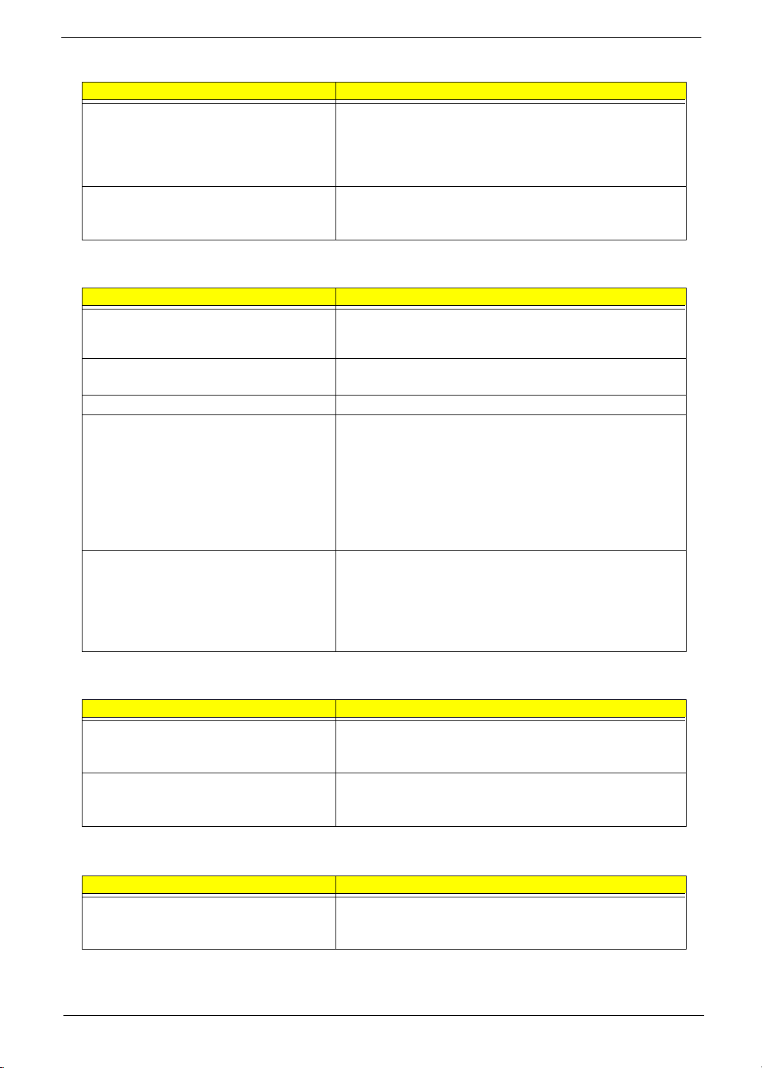
Power Management-Related Symptoms
Symptom / Error Action in Sequence
Battery fuel gauge in Windows doesn’t go higher
than 90%.
System hangs intermittently. Reconnect hard disk/CD-ROM drives.
Remove battery pack and let it cool for 2 hours.
Refresh battery (continue use battery until power off, then charge
battery).
Battery pack
System board
Hard disk connection board
System board
Peripheral-Related Symptoms
Symptom / Error Action in Sequence
System configuration does not match the
installed devices.
External display does not work correctly. Press Fn+F5, LCD/CRT/Both display switching
USB does not work correctly System board
Print problems. Ensure the “Parallel Port” in the “Onboard Devices Configuration” of
Serial or parallel port device problems. Ensure the “Serial Port” in the Devices Configuration” of BIOS Setup
Enter BIOS Setup Utility to execute “Load Default Settings”, then
reboot system.
Reconnect hard disk/CD-ROM/diskette drives.
System board
BIOS Setup Utility is set to Enabled.
Onboard Devices Configuration
Run printer self-test.
Printer driver
Printer cable
Printer
System Board
Utility is set to Enabled.
Device driver
Device cable
Device
System board
Keyboard/Touchpad-Related Symptoms
Symptom / Error Action in Sequence
Keyboard (one or more keys) does not work. Reconnect the keyboard cable.
Keyboard
System board
Touchpad does not work. Reconnect touchpad cable.
Touchpad board
System board
Modem-Related Symptoms
Symptom / Error Action in Sequence
Internal modem does not work correctly. Modem phone port
modem combo board
System board
NOTE: If you cannot find a symptom or an error in this list and the problem remains, see “Undetermined
Problems” on page 82.
Chapter 4 80
Page 91

Intermittent Problems
Intermittent system hang problems can be caused by a variety of reasons that have nothing to do with a
hardware defect, such as: cosmic radiation, electrostatic discharge, or software errors. FRU replacement
should be considered only when a recurring problem exists.
When analyzing an intermittent problem, do the following:
1. Run the advanced diagnostic test for the system board in loop mode at least 10 times.
2. If no error is detected, do not replace any FRU.
3. If any error is detected, replace the FRU. Rerun the test to verify that there are no more errors.
81 Chapter 4
Page 92

Undetermined Problems
The diagnostic problems does not identify which adapter or device failed, which installed devices are incorrect,
whether a short circuit is suspected, or whether the system is inoperative.
Follow these procedures to isolate the failing FRU (do not isolate non-defective FRU).
NOTE: Verify that all attached devices are supported by the computer.
NOTE: Verify that the power supply being used at the time of the failure is operating correctly. (See “Power
System Check” on page 70):
1. Power-off the computer.
2. Visually check them for damage. If any problems are found, replace the FRU.
3. Remove or disconnect all of the following devices:
T Non-Acer devices
T Printer, mouse, and other external devices
T Battery pack
T Hard disk drive
T DIMM
T CD-ROM/Diskette drive Module
T PC Cards
4. Power-on the computer.
5. Determine if the problem has changed.
6. If the problem does not recur, reconnect the removed devices one at a time until you find the failing FRU.
7. If the problem remains, replace the following FRU one at a time. Do not replace a non-defective FRU:
T System board
T LCD assembly
Chapter 4 82
Page 93
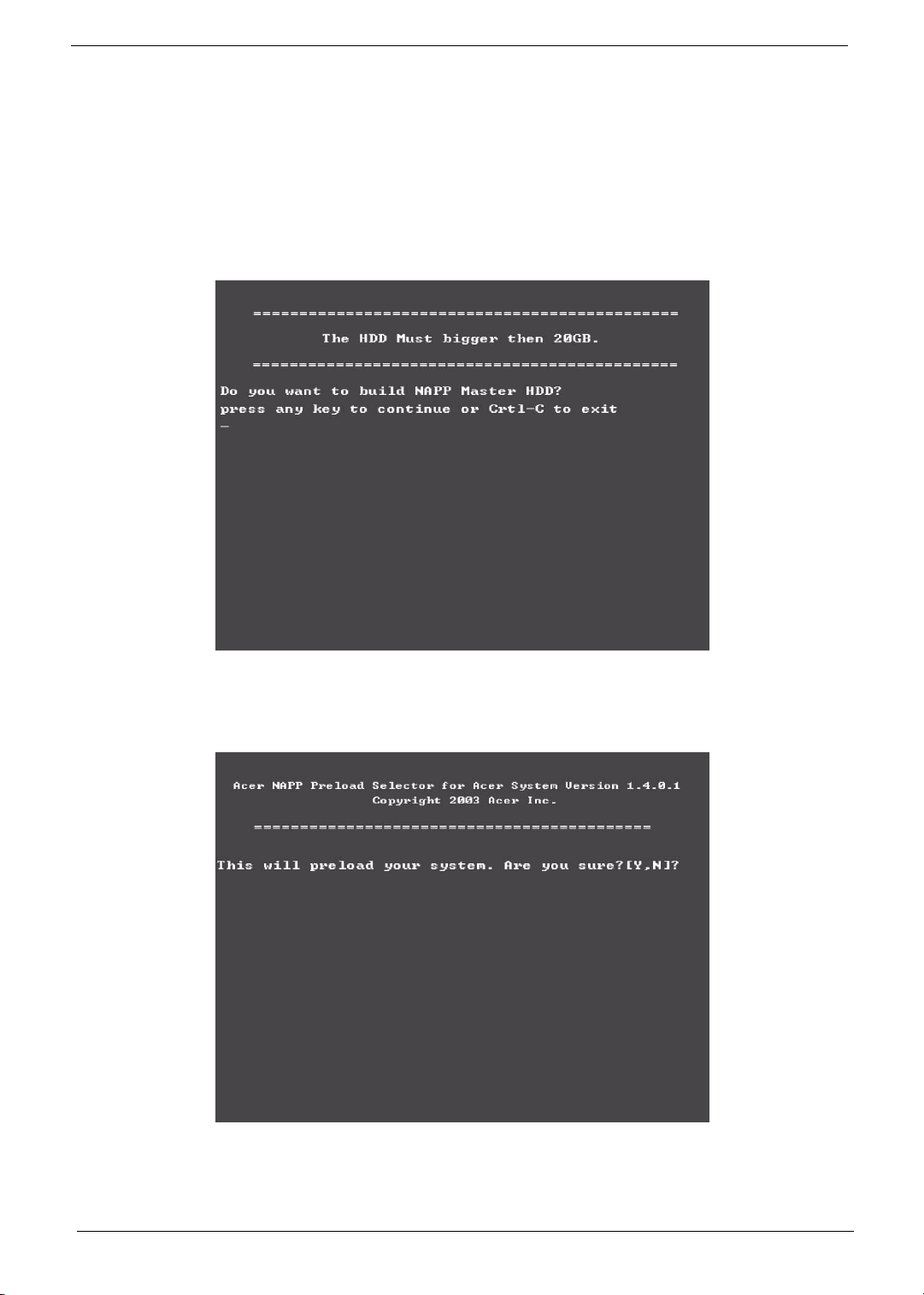
Use NAPP CD to Build Master Hard Disc Drive
CD to Disk Recovery
1. Prepare NAPP CD, Recovery CD and System CD.
2. Put NAPP CD into the optical drive. Then boot up the system.
3. The system will ask you if you want to build NAPP Master HDD. Please press any key to continue.
4. NAPP CD will start to preload the system, please click [Y].
5. Select CD to Disk Revocery.
83 Chapter 4
Page 94
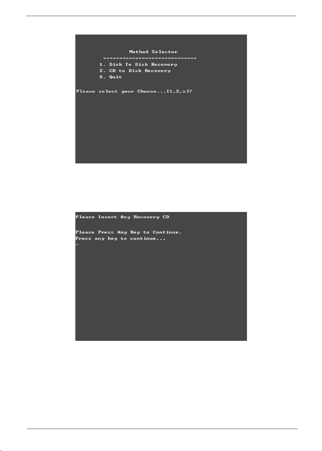
6. Put the Recovery CD to the optical drive. This step is to create image files to the system, you do not have
to put the Recovery CD to the optical drive in order. Place one Recovery CD to the drive at one time till
you finish all Recovery CDs.
After you place the Recovery CD to the optical drive, you will see the display below.
Chapter 4 84
Page 95
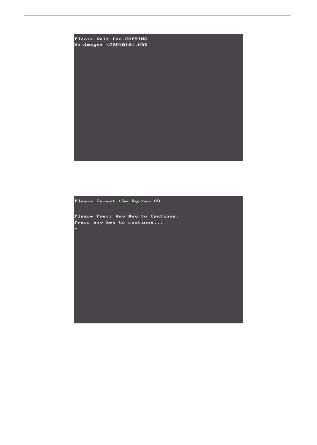
7. Then insert the System CD to the optical drive.
8. You will see the screen displaying “PASS” when the system has buit NAPP Master hard disc drive.
85 Chapter 4
Page 96
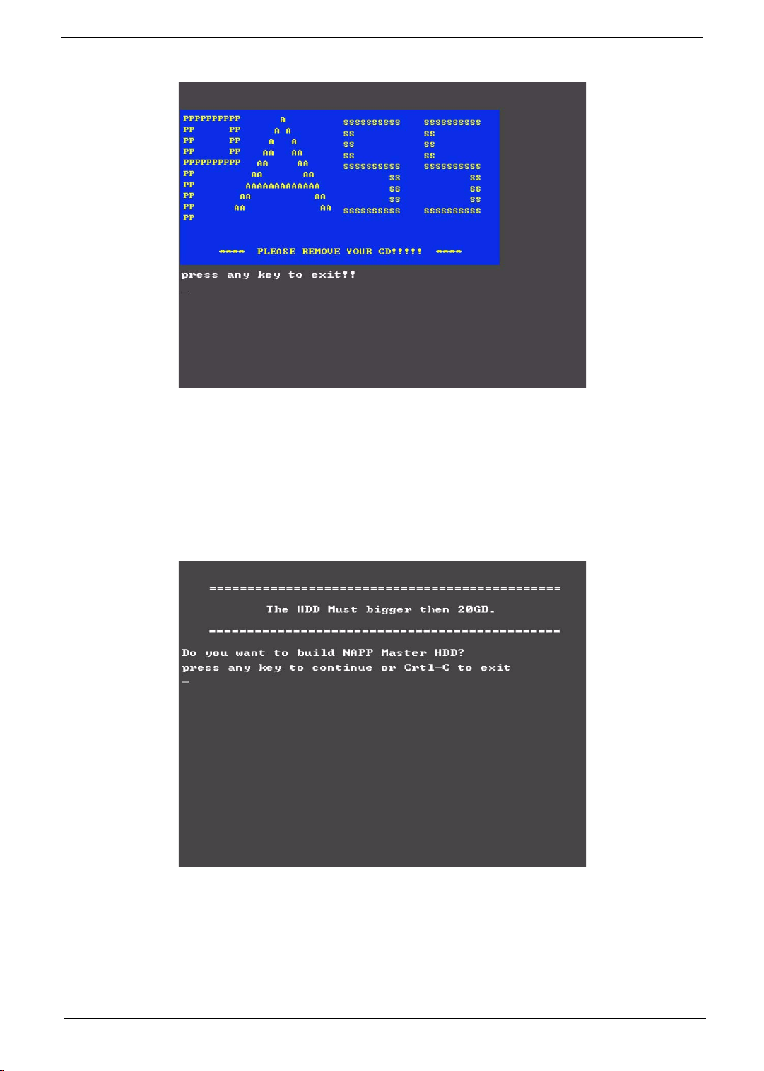
Disk to Disk Recovery
1. Prepare NAPP CD, Recovery CD and System CD.
2. Put NAPP CD into the optical drive. Then boot up the system.
3. The system will ask you if you want to build NAPP Master HDD. Please press any key to continue.
4. NAPP CD will start to preload the system, please click [Y].
Chapter 4 86
Page 97
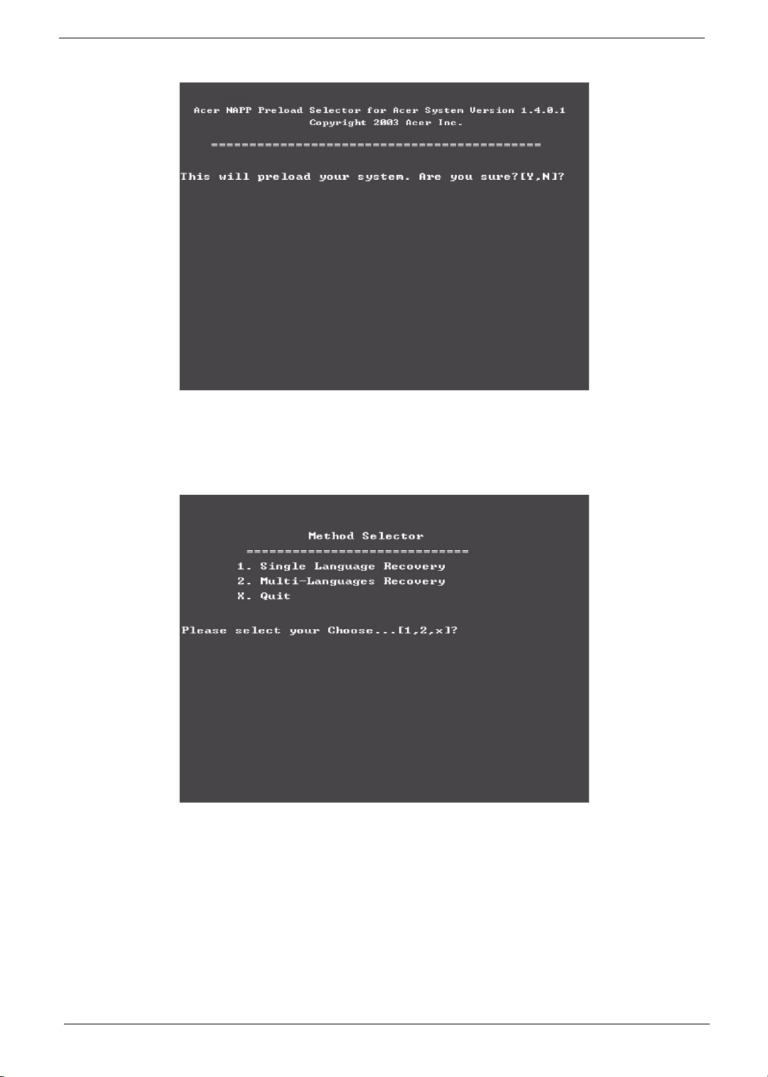
5. Select Disk to Disk Recovery. Then choose Single Language or Multi-Languages Recovery.
NOTE: For Multi-Languages Recovery, not more than five languages could be loaded to the system.
6. Put the Recovery CD to the optical drive. This step is to create image files to the system, you do not have
to put the Recovery CD to the optical drive in order. Place one Recovery CD to the drive at one time till
you finish all Recovery CDs.
87 Chapter 4
Page 98
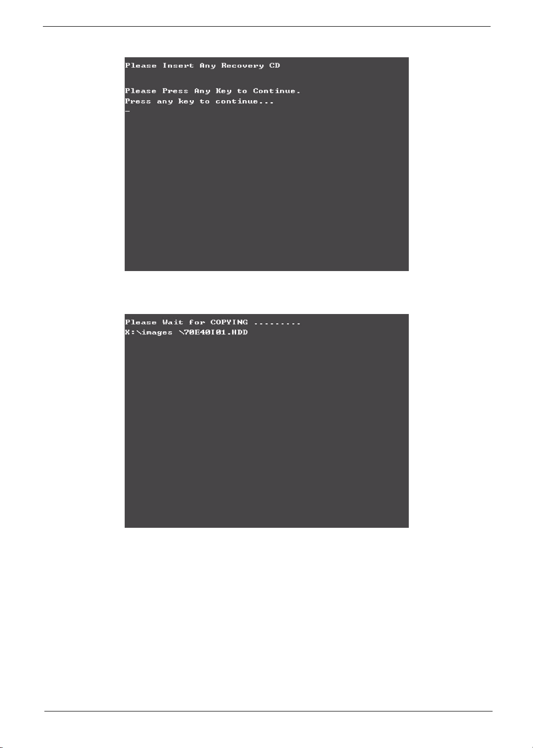
After you place the Recovery CD to the optical drive, you will see the display below.
7. Then insert the System CD to the optical drive.
Chapter 4 88
Page 99
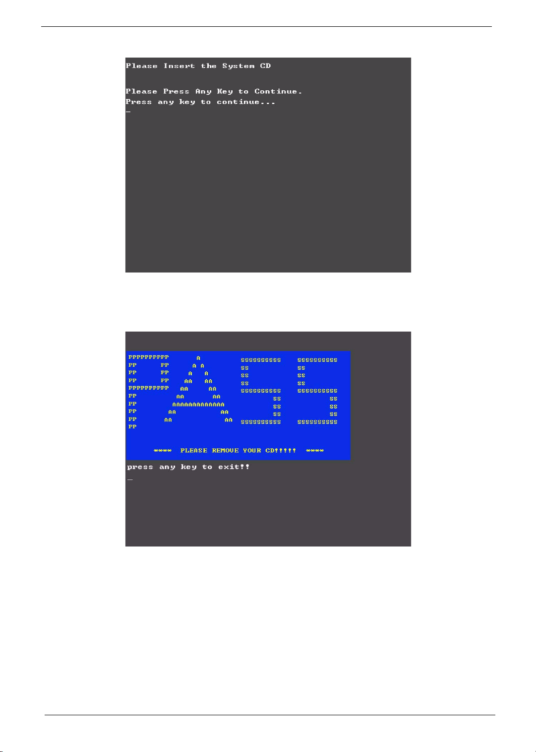
8. You will see the screen displaying “PASS” when the system has buit NAPP Master hard disc drive.
89 Chapter 4
Page 100
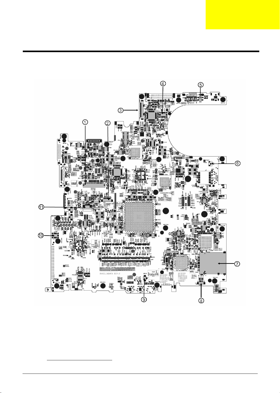
Jumper and Connector Locations
Top Vi e w
Chapter 5
1 Keyboard Connector CN5 7 3 in 1 Connector CN10
2 Bluetooth Board Connector CN6 8 Speaker Connector CN12
3 LCD Cable Connector CN2 9 Internal Microphone Connector CN11
Chapter 5 90
 Loading...