


Aspire 1360/1520 Series
Service Guide
PRINTED IN TAIWAN

Revision History
Please refer to the table below for the updates made on Aspire 1360/1520 service guide.
Date Chapter Updates
2004/10/20 Chapter 1 Add the most up-to-date system block diagram on page 3.
Change the memory controller to “built-in CPU” on page 18.
II

Copyright
Copyright © 2004 by Acer Incorporated. All rights reserved. No part of this publication may be reproduced,
transmitted, transcribed, stored in a retrieval system, or translated into any language or computer language, in
any form or by any means, electronic, mechanical, magnetic, optical, chemical, manual or otherwise, without
the prior written permission of Acer Incorporated.
Disclaimer
The information in this guide is subject to change without notice.
Acer Incorporated makes no representations or warranties, either expressed or implied, with respect to the
contents hereof and specifically disclaims any warranties of merchantability or fitness for any particular
purpose. Any Acer Incorporated software described in this manual is sold or licensed "as is". Should the
programs prove defective following their purchase, the buyer (and not Acer Incorporated, its distributor, or its
dealer) assumes the entire cost of all necessary servicing, repair, and any incidental or consequential
damages resulting from any defect in the software.
Intel is a registered trademark of Intel Corporation.
Pentium and Pentium II/III are trademarks of Intel Corporation.
Other brand and product names are trademarks and/or registered trademarks of their respective holders.
III
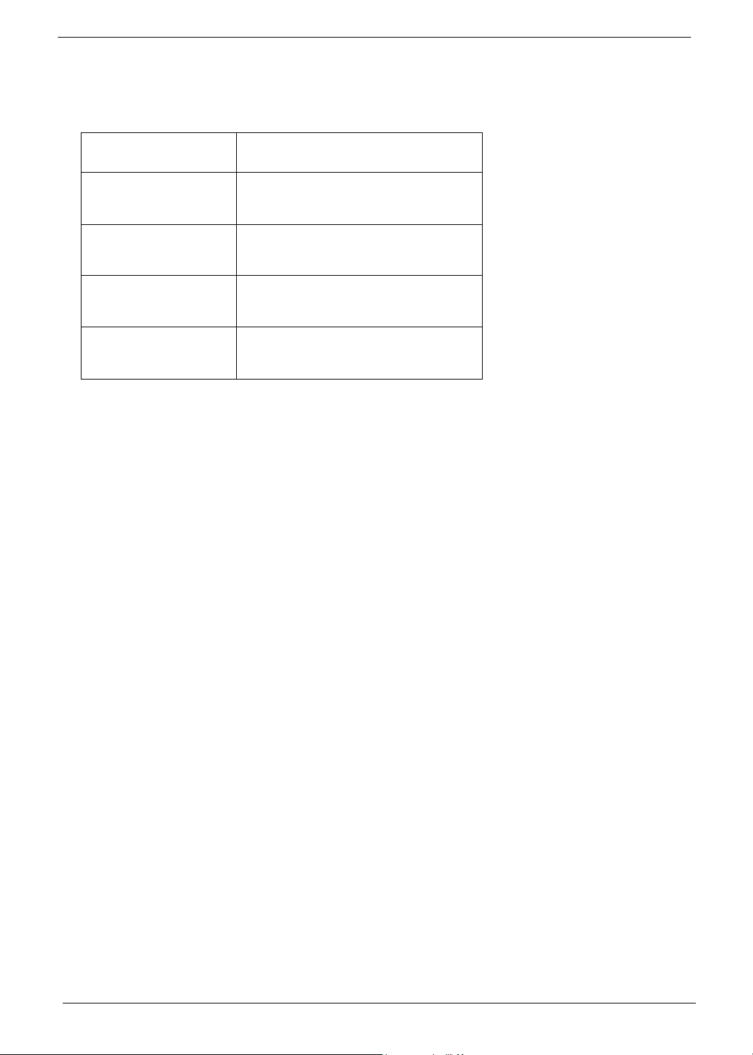
Conventions
The following conventions are used in this manual:
Screen messages Denotes actual messages that appear
on screen.
NOTE Gives bits and pieces of additional
information related to the current
topic.
WARNING Alerts you to any damage that might
result from doing or not doing specific
actions.
CAUTION Gives precautionary measures to
avoid possible hardware or software
problems.
IMPORTANT Reminds you to do specific actions
relevant to the accomplishment of
procedures.
IV

Preface
Before using this information and the product it supports, please read the following general information.
1. This Service Guide provides you with all technical information relating to the BASIC CONFIGURATION
decided for Acer "global" product offering. To better fit local market requirements and enhance product
competitiveness, your regional office MAY have decided to extend the functionality of a machine (e.g.
add-on card, modem, or extra memory capability). These LOCALIZED FEATURES will NOT be covered
in this generic service guide. In such cases, please contact your regional offices or the responsible
personnel/channel to provide you with further technical details.
2. Please note WHEN ORDERING FRU PARTS, that you should check the most up-to-date information
available on your regional web or channel. If, for whatever reason, a part number change is made, it will
not be noted in the printed Service Guide. For ACER AUTHORIZED SERVICE PROVIDERS, your Acer
office may have a DIFFERENT part number code to those given in the FRU list of this printed Service
Guide. You MUST use the list provided by your regional Acer office to order FRU parts for repair and
service of customer machines.
V

VI

Table of Contents
Chapter 1 System Introduction 1
Features . . . . . . . . . . . . . . . . . . . . . . . . . . . . . . . . . . . . . . . . . . . . . . . . . . . . . . . . . . . .1
System Block Diagram . . . . . . . . . . . . . . . . . . . . . . . . . . . . . . . . . . . . . . . . . . . . . . . . .3
Board Layout . . . . . . . . . . . . . . . . . . . . . . . . . . . . . . . . . . . . . . . . . . . . . . . . . . . . . . . .4
Top View . . . . . . . . . . . . . . . . . . . . . . . . . . . . . . . . . . . . . . . . . . . . . . . . . . . . . . . .4
Bottom View . . . . . . . . . . . . . . . . . . . . . . . . . . . . . . . . . . . . . . . . . . . . . . . . . . . . .5
Panel . . . . . . . . . . . . . . . . . . . . . . . . . . . . . . . . . . . . . . . . . . . . . . . . . . . . . . . . . . . . . . .6
Front View . . . . . . . . . . . . . . . . . . . . . . . . . . . . . . . . . . . . . . . . . . . . . . . . . . . . . . .6
Left view . . . . . . . . . . . . . . . . . . . . . . . . . . . . . . . . . . . . . . . . . . . . . . . . . . . . . . . .7
Right View . . . . . . . . . . . . . . . . . . . . . . . . . . . . . . . . . . . . . . . . . . . . . . . . . . . . . . .8
Rear Panel . . . . . . . . . . . . . . . . . . . . . . . . . . . . . . . . . . . . . . . . . . . . . . . . . . . . . .9
Bottom View . . . . . . . . . . . . . . . . . . . . . . . . . . . . . . . . . . . . . . . . . . . . . . . . . . . .10
Indicators . . . . . . . . . . . . . . . . . . . . . . . . . . . . . . . . . . . . . . . . . . . . . . . . . . . . . . . . . .11
Keyboard . . . . . . . . . . . . . . . . . . . . . . . . . . . . . . . . . . . . . . . . . . . . . . . . . . . . . . . . . .12
Special keys . . . . . . . . . . . . . . . . . . . . . . . . . . . . . . . . . . . . . . . . . . . . . . . . . . . .12
Hot Keys . . . . . . . . . . . . . . . . . . . . . . . . . . . . . . . . . . . . . . . . . . . . . . . . . . . . . . . . . . .15
Hardware Specifications and Configurations . . . . . . . . . . . . . . . . . . . . . . . . . . . . . . .18
Chapter 2 System Utilities 32
BIOS Setup Utility . . . . . . . . . . . . . . . . . . . . . . . . . . . . . . . . . . . . . . . . . . . . . . . . . . . .32
Navigating the BIOS Utility . . . . . . . . . . . . . . . . . . . . . . . . . . . . . . . . . . . . . . . . .33
Information . . . . . . . . . . . . . . . . . . . . . . . . . . . . . . . . . . . . . . . . . . . . . . . . . . . . .34
Main . . . . . . . . . . . . . . . . . . . . . . . . . . . . . . . . . . . . . . . . . . . . . . . . . . . . . . . . . .35
Advanced . . . . . . . . . . . . . . . . . . . . . . . . . . . . . . . . . . . . . . . . . . . . . . . . . . . . . .37
Security . . . . . . . . . . . . . . . . . . . . . . . . . . . . . . . . . . . . . . . . . . . . . . . . . . . . . . . .39
Boot . . . . . . . . . . . . . . . . . . . . . . . . . . . . . . . . . . . . . . . . . . . . . . . . . . . . . . . . . . .43
Exit . . . . . . . . . . . . . . . . . . . . . . . . . . . . . . . . . . . . . . . . . . . . . . . . . . . . . . . . . . .44
BIOS Flash Utility . . . . . . . . . . . . . . . . . . . . . . . . . . . . . . . . . . . . . . . . . . . . . . . . . . . .45
Chapter 3 Machine Disassembly and Replacement 46
General Information . . . . . . . . . . . . . . . . . . . . . . . . . . . . . . . . . . . . . . . . . . . . . . . . . .47
Before You Begin . . . . . . . . . . . . . . . . . . . . . . . . . . . . . . . . . . . . . . . . . . . . . . . .47
Disassembly Procedure Flowchart . . . . . . . . . . . . . . . . . . . . . . . . . . . . . . . . . . . . . . .48
Removing the Battery . . . . . . . . . . . . . . . . . . . . . . . . . . . . . . . . . . . . . . . . . . . . . . . . .50
Removing the Memory Module . . . . . . . . . . . . . . . . . . . . . . . . . . . . . . . . . . . . . . . . . .51
Removing the Wireless LAN Board and the Modem Board . . . . . . . . . . . . . . . . . . . .52
Removing the Hard Disk Drive Module . . . . . . . . . . . . . . . . . . . . . . . . . . . . . . . . . . . .53
Disassembling the Hard Disk Drive Module . . . . . . . . . . . . . . . . . . . . . . . . . . . .53
Removing the LCD Module . . . . . . . . . . . . . . . . . . . . . . . . . . . . . . . . . . . . . . . . . . . . .54
Removing the Middle Cover . . . . . . . . . . . . . . . . . . . . . . . . . . . . . . . . . . . . . . . .54
Removing the Launch Board . . . . . . . . . . . . . . . . . . . . . . . . . . . . . . . . . . . . . . .54
Removing the LCD Module . . . . . . . . . . . . . . . . . . . . . . . . . . . . . . . . . . . . . . . . .55
Disassembling the LCD Module . . . . . . . . . . . . . . . . . . . . . . . . . . . . . . . . . . . . . . . . .57
Removing the LCD Bezel . . . . . . . . . . . . . . . . . . . . . . . . . . . . . . . . . . . . . . . . . .57
Removing the Inverter Board (15” LCD) . . . . . . . . . . . . . . . . . . . . . . . . . . . . . . .57
Removing the 15” TFT LCD . . . . . . . . . . . . . . . . . . . . . . . . . . . . . . . . . . . . . . . .58
Removing the LCD Brackets . . . . . . . . . . . . . . . . . . . . . . . . . . . . . . . . . . . . . . . .59
Removing the LCD Coaxial Cable . . . . . . . . . . . . . . . . . . . . . . . . . . . . . . . . . . .59
Removing the LCD Hinges . . . . . . . . . . . . . . . . . . . . . . . . . . . . . . . . . . . . . . . . .60
Disassembling the Main Unit . . . . . . . . . . . . . . . . . . . . . . . . . . . . . . . . . . . . . . . . . . .61
Removing the Keyboard . . . . . . . . . . . . . . . . . . . . . . . . . . . . . . . . . . . . . . . . . . .61
Removing the RTC Battery . . . . . . . . . . . . . . . . . . . . . . . . . . . . . . . . . . . . . . . . .61
VII

Table of Contents
Removing the Fan . . . . . . . . . . . . . . . . . . . . . . . . . . . . . . . . . . . . . . . . . . . . . . . .61
Removing the Thermal Module . . . . . . . . . . . . . . . . . . . . . . . . . . . . . . . . . . . . . .62
Removing the Processor . . . . . . . . . . . . . . . . . . . . . . . . . . . . . . . . . . . . . . . . . . .62
Installing the Processor . . . . . . . . . . . . . . . . . . . . . . . . . . . . . . . . . . . . . . . . . . . .63
Removing the Upper Case Assemly . . . . . . . . . . . . . . . . . . . . . . . . . . . . . . . . . .63
Removing the Touchpad Board . . . . . . . . . . . . . . . . . . . . . . . . . . . . . . . . . . . . .64
Removing the Touchpad Cable . . . . . . . . . . . . . . . . . . . . . . . . . . . . . . . . . . . . .64
Removing the VGA Thermal Plate . . . . . . . . . . . . . . . . . . . . . . . . . . . . . . . . . . .65
Removing the CPU Heatsink Plate . . . . . . . . . . . . . . . . . . . . . . . . . . . . . . . . . . .65
Removing the Second Fan Bracket . . . . . . . . . . . . . . . . . . . . . . . . . . . . . . . . . .66
Removing the ODD Module(1) . . . . . . . . . . . . . . . . . . . . . . . . . . . . . . . . . . . . . .66
Removing the ODD Module(2) . . . . . . . . . . . . . . . . . . . . . . . . . . . . . . . . . . . . . .66
Removing the HDD Bracket . . . . . . . . . . . . . . . . . . . . . . . . . . . . . . . . . . . . . . . .67
Removing the Main Board . . . . . . . . . . . . . . . . . . . . . . . . . . . . . . . . . . . . . . . . .67
Removing the DC Board . . . . . . . . . . . . . . . . . . . . . . . . . . . . . . . . . . . . . . . . . . .68
Removing the I/O Port Bracket . . . . . . . . . . . . . . . . . . . . . . . . . . . . . . . . . . . . . .68
Removing the PCMCIA Slot . . . . . . . . . . . . . . . . . . . . . . . . . . . . . . . . . . . . . . . .69
Removing the Speaker Set . . . . . . . . . . . . . . . . . . . . . . . . . . . . . . . . . . . . . . . . .70
System Upgrade Procedure . . . . . . . . . . . . . . . . . . . . . . . . . . . . . . . . . . . . . . . . . . . .71
Base Unit to Wireless Unit . . . . . . . . . . . . . . . . . . . . . . . . . . . . . . . . . . . . . . . . .71
Chapter 4 Troubleshooting 72
System Check Procedures . . . . . . . . . . . . . . . . . . . . . . . . . . . . . . . . . . . . . . . . . . . . .73
External Diskette Drive Check . . . . . . . . . . . . . . . . . . . . . . . . . . . . . . . . . . . . . .73
External CD-ROM Drive Check . . . . . . . . . . . . . . . . . . . . . . . . . . . . . . . . . . . . .73
Keyboard or Auxiliary Input Device Check . . . . . . . . . . . . . . . . . . . . . . . . . . . . .73
Memory check . . . . . . . . . . . . . . . . . . . . . . . . . . . . . . . . . . . . . . . . . . . . . . . . . . .74
Power System Check . . . . . . . . . . . . . . . . . . . . . . . . . . . . . . . . . . . . . . . . . . . . .74
Touchpad Check . . . . . . . . . . . . . . . . . . . . . . . . . . . . . . . . . . . . . . . . . . . . . . . . .76
Power-On Self-Test (POST) Error Message . . . . . . . . . . . . . . . . . . . . . . . . . . . . . . .77
Index of Error Messages . . . . . . . . . . . . . . . . . . . . . . . . . . . . . . . . . . . . . . . . . . . . . . .78
POST Code . . . . . . . . . . . . . . . . . . . . . . . . . . . . . . . . . . . . . . . . . . . . . . . . . . . . . . . .81
Index of Symptom-to-FRU Error Message . . . . . . . . . . . . . . . . . . . . . . . . . . . . . . . . .85
Intermittent Problems . . . . . . . . . . . . . . . . . . . . . . . . . . . . . . . . . . . . . . . . . . . . . . . . .88
Undetermined Problems . . . . . . . . . . . . . . . . . . . . . . . . . . . . . . . . . . . . . . . . . . . . . . .89
How to Build NAPP Master Hard Disc Drive . . . . . . . . . . . . . . . . . . . . . . . . . . . . . . . .90
CD to Disk Recovery . . . . . . . . . . . . . . . . . . . . . . . . . . . . . . . . . . . . . . . . . . . . . .90
Disk to Disk Recovery . . . . . . . . . . . . . . . . . . . . . . . . . . . . . . . . . . . . . . . . . . . . .93
Chapter 5 Jumper and Connector Locations 98
Top View . . . . . . . . . . . . . . . . . . . . . . . . . . . . . . . . . . . . . . . . . . . . . . . . . . . . . . .98
Bottom View . . . . . . . . . . . . . . . . . . . . . . . . . . . . . . . . . . . . . . . . . . . . . . . . . . . .99
Chapter 6 FRU (Field Replaceable Unit) List 100
Aspire 1660 Exploded Diagram . . . . . . . . . . . . . . . . . . . . . . . . . . . . . . . . . . . . . . . .101
Appendix A Model Definition and Configuration 112
Model Name Definition . . . . . . . . . . . . . . . . . . . . . . . . . . . . . . . . . . . . . . . . . . . . . . .112
Appendix B Test Compatible Components 114
Microsoft Windows XP Environment Test . . . . . . . . . . . . . . . . . . . . . . . . . . . . . . . . .115
Appendix C Online Support Information 120
VIII

IX

System Introduction
Features
This computer was designed with the user in mind. Here are just a few of its many features:
Performance
T Mobile AMD Sempron
supporting AMD Power Now! Technology and HyperTransport technology (for Aspire 1360 only)
T AMD Athlon 64 processor 3000+ to 3400+ or higher with 1 MB cache, supporting HyperTransport
technology (for Aspire 1520 only)
T VIA Chipset-integrated Unichrome PRO graphics core, with up to 64MB of shared memory
T 256/512MB of DDR333 SDRAM, upgradeable to 2048MB with dual soDIMM modules
T 30GB and above high-capacity, Enhanced-IED hard disk (for Aspire 1360 only)
T 40GB and above high-capacity, Enhanced-IDE hard disk (for Aspire 1520 only)
T Advanced Configuration Power Interface (ACPI) power management system
Display
T The TFT LCD panel providing a large viewing area for maximum efficiency and ease-of-use:
-- 14.1” XGA (1024x768) resolution (for Aspire 1360 only)
-- 15.0” XGA (1024x768) or SXGA+ (1400x1050) resolution
-- 15.4” WXGA (1280x800)
T NVIDIA GeForce4 448 Go with 64MB of video memory (manufacturing option)
T NVIDIA GeForce FX Go5200 with 64MB of video memory (manufacturing option)
T NVIDIA GeForce FX Go5700 with 64MB of video memory (manufacturing option)
T 3D graphics support
T Support simultanesous display between LCD and CRT
T S-video for output to a television or display device that supports S-video input
T “Automatic LCD dim” feature, automatically selecting the best setting for the display in order to
conserve power
T DualView
TM
support
TM
processor 2600+ to 3300+ or higher with 128/256 KB L2 cache,
Chapter 1
Multimedia
T High-speed built-in optical drive:
DVD/CD-RW Combo, or DVD-Dual or DVD Super-Multi
T MS DirectSound compatible
T Built-in dual speakers
Connectivity
T Integrated 10/100 Mbps Fast Ethernet connection (for Aspire 1360 only)
T Integrated 10/100/1000 Mbps Fast Ethernet connection (for Aspire 1520 only)
T Built-in 56Kbps fax/data modem
Chapter 1 1

T Four Universal Serial Bus (USB) 2.0 ports
T One IEEE 1394 port
T IEEE 802.11b/g Wireless LAN (manufacturing option)
T Bluetooth
Expansion
T One Type III or two Type II CardBus PC Card slots
T Upgradeable hard disk and memory modules
Human-centric design
T Rugged, yet extremely portable, construction
T Stylish appearance
T Full-size keyboard with four programmable launch keys
T Comfortable palm rest area with well-positioned touchpad
I/O Ports
T Two Type II or one Type III PC CardBus (PCMCIA) slot
T One IEEE 1394 port
T One FIR port
T One RJ-11 modem jack (V.92, 56K)
T One RJ-45 network jack(Ethernet 10/100 Base-T)
T One DC-in jack
T One parallel port (ECP/EPP)
T One S-video port
T One external monitor port
T One microphone-in jack (3.5mm mini jack)
T One headphone jack (3.5mm mini jack)
T Four USB 2.0 ports
®
(manufacturing option)
2 Chapter 1
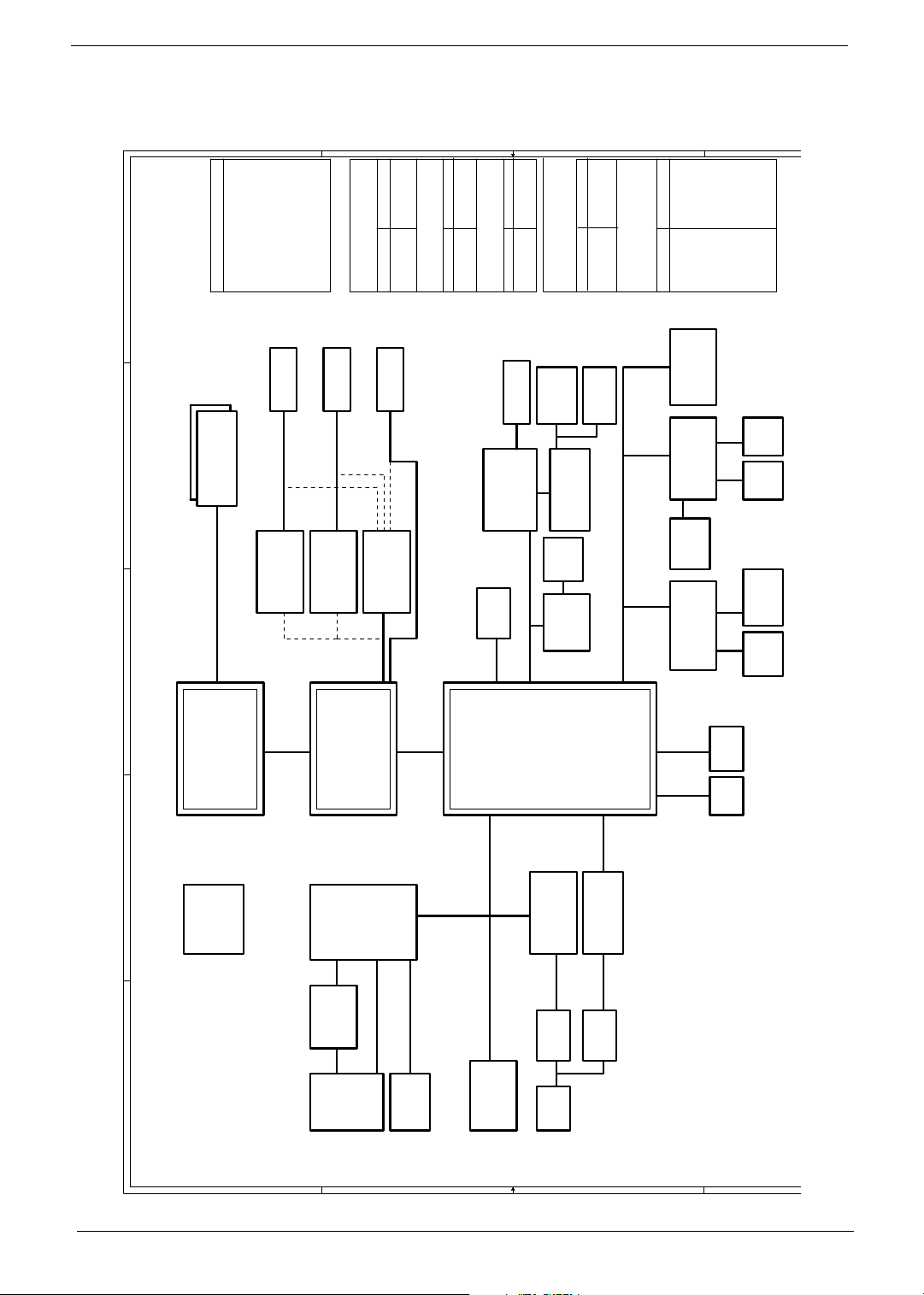
System Block Diagram
L1: Signal 1
L2: GND
PCB Layer Stackup
8,9,10
DDR x2
200-PIN DDR SODIMM
DDR 333/400
L3: Signal 2
L4: Signal 3
L5: VCC
17
TVOUT
SVIDEO/COMP
14
VIA VT1623M
TV Encoder
46
L6: Signal 4
Battery Charger
18
LCD
LVDS
15
VIA VT1631
LVDS Transmitter
43
OUTPUTS
DCBATOUT
MAX1645BEEI
AD+
BAT+
INPUTS
17
CRT
RGB CRT
16
AGP 8X
Graphic CONN.
AGP 8x
44
OUTPUT
5V_S5 ,
3D3V_S5
SYSTEM DC/DC
INPUT
DCBATOUT
TPS5110
MAX1999
SYSTEM DC/DC
AC'97 CODEC
24
USB x 4
OUTPUT
2D5V_S3
INPUT
DCBATOUT
32
Line In
VT1612A
1D5V_S0
2D5V_S3
MIC In
31
AC LINK
41,42
VCC_CORE_S0
OUTPUT
ISL6559CR
CPU V_CORE
INPUT
DCBATOUT
32
Int. SPKR
Line Out
(SPDIF)
3224
OP AMP
APA2020
29
RJ11
CONN
MDC Card
MODEM
44,45
OUTPUT
2D5V_S5
5V_S0
SYSTEM POWER
INPUT
FDD6035AL/FDS9412-U
APL5508-18VC/APL5308-25AC
FDS9412-U/SI4892DY/LP2951ACM
32
FWH
KBC
LPC Bus / 33MHz
Thermal
NS SIO
3D3V_S3
3D3V_S0
3D3V_LAN_S3
5V_S3
3D3V_S5
3D3V_S3
3D3V_S0
3533
SST-49LF040
M38859
22
& Fan
G791
36
PC87392
1D8V_S0
+5V_AUX_S5
+5V_UP_S5
DCBATOUT
2D5V_S0
Int.
Touch
FIRParallel
KB
34 34
Pad
36
TFDU6101E
37
port
VIA
K8N800
AGTL+ CPU I/F + UMA
11,12,13
4,5,6,7
AMD CPU
Claw Hammer K8
HyperTransport
6.4GB/S 16b/8b
EGRET Block Diagram
3
ICS
CLK GEN
ICS950405
A B C D E
4 4
TI
2* Slot Cardbus
PCI 7420
27
PWR SW
TPS2224AP
PCMCIA
SLOT
1* 1394
PCMCIA I/F
27
Support
TypeII
8 bit V-LINK
66MHZ
8x/4x/2x
25,26
27
1394
Conn
3 3
6xUSB 2.0
VIA
VT8235CE
ACPI 2.0
PCI Bus / 33MHz
Mini-PCI
LPC I/F
MII
LAN PHY29VIA VT6103L
10/100Mb
29
TXFM
2 2
19,20,21
ATA 133
SIDE
PIDE
DVD/
HDD
23
CD-RW
23
6-CH
AC97 2.2
PCI
28
PCI GIGA LAN
Realtek
RTL8110SBL
1000Mb
29
TXFM
30
29
802.11a/b/g
RJ45
Chapter 1 3
Board Layout
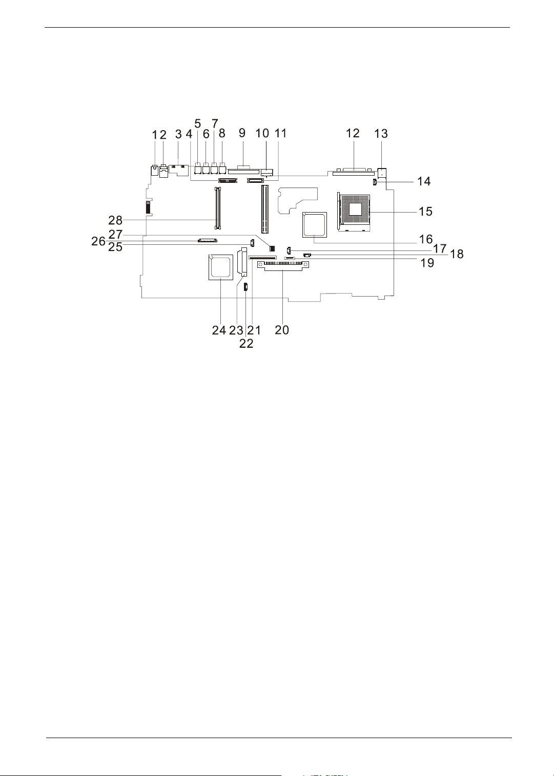
Top Vi e w
1 Line-in Port 15 CPU Socket
2 Line-out Port 16 North Bridge
3 RJ45+RJ11 17 Fan Connector
4 LCD Inverter Cable Connector 18 Note: There is no 18 on this main board.
5 USB Port 19 Touchpad Cable Connector
6 USB Port 20 HDD Connector
7 USB Port 21 Keyboard Connector
8 USB Port 22 Speaker Cable Connector
9 VGA Port 23 Optical Drive Connector
10 S-Video Port 24 South Bridge
11 LCD Coaxial Cable Connector 25 RTC Battery Connector
12 Parallel Port 26 Launch Board Cable Connector
13 DC-in Port 27 SW1 (Please see Chapter 5 for its settings)
14 LCD Lid Switch 28 PCMCIA Slot
4 Chapter 1
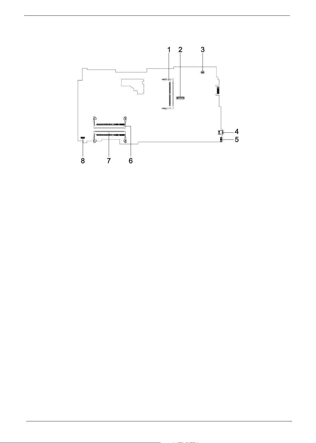
Bottom View
1 Wireless LAN Card Connector 5 FIR Port
2 Modem Board Connector 6 DIMM Socket 1
3 Modem Cable Connector 7 DIMM Socket 2
4 IEEE 1394 Port 8 DC Charger Board Connector
Chapter 1 5
Panel
Ports allow you to connect peripheral devices to your computer as you would with a desktop PC.
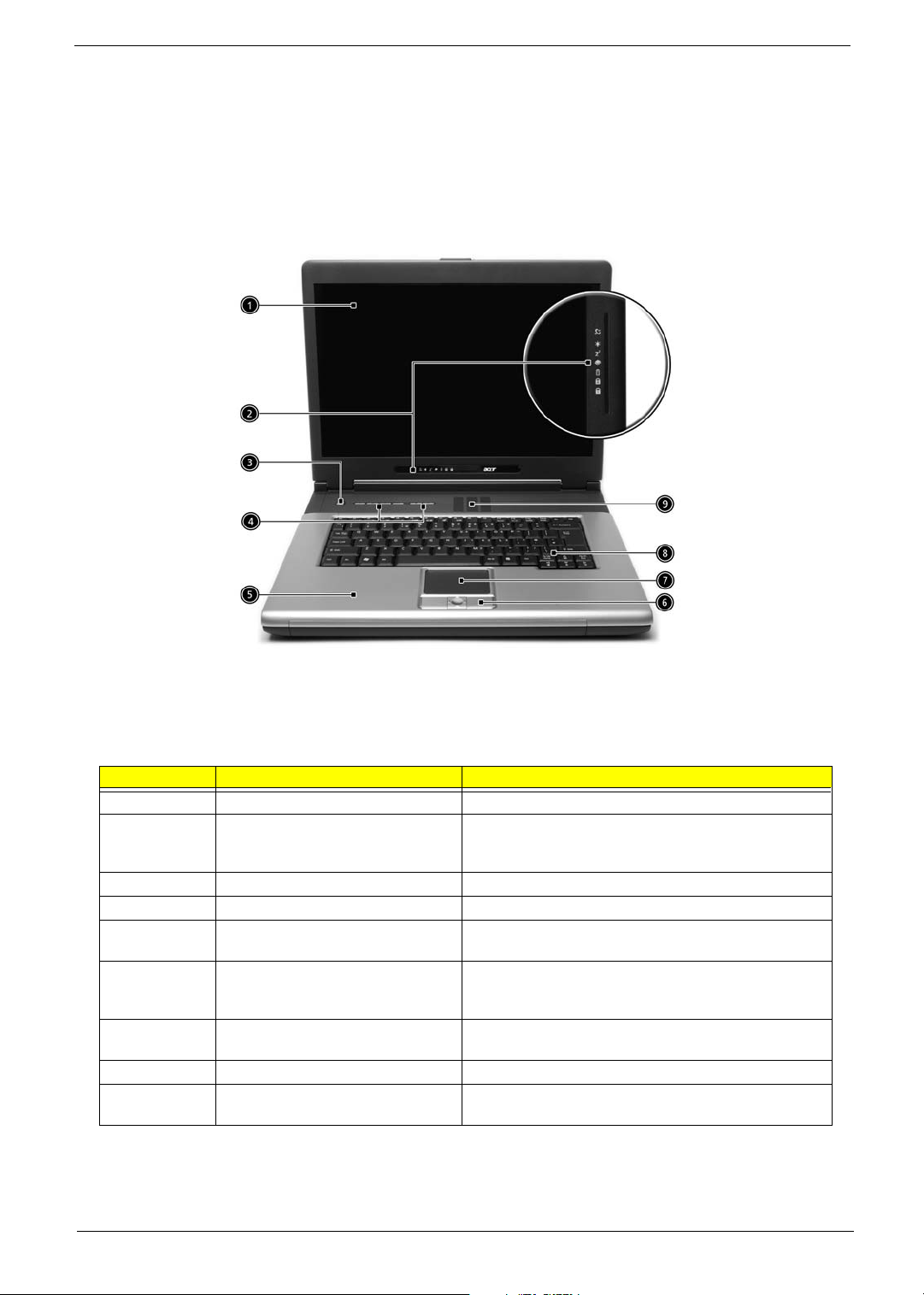
Front View
# Item Description
1 Display screen Liquid-Crystal Display (LCD) provides visual output.
2 Status indicators LEDs (Light Emitting Diodes) that turn on and off to show
3 Power button Turns the computer on and off.
4 Launch Keys Buttons for launching frequently used programs.
5 Palmrest Comfortable support area for your hands when you use the
6 Click buttons & 4-way scroll key The left and right buttons function like the left and right
7 Touchpad Touch-sensitive pointing device which functions like a
8 Keyboard Inputs data into your computer.
9 Ventilation Slot Enables the computer to stay cool, even after the
the status of the computer and its functions and
components.
computer.
mouse buttons, the center button serves as a scroll up/
down button.
computer mouse.
prolonged use.
6 Chapter 1
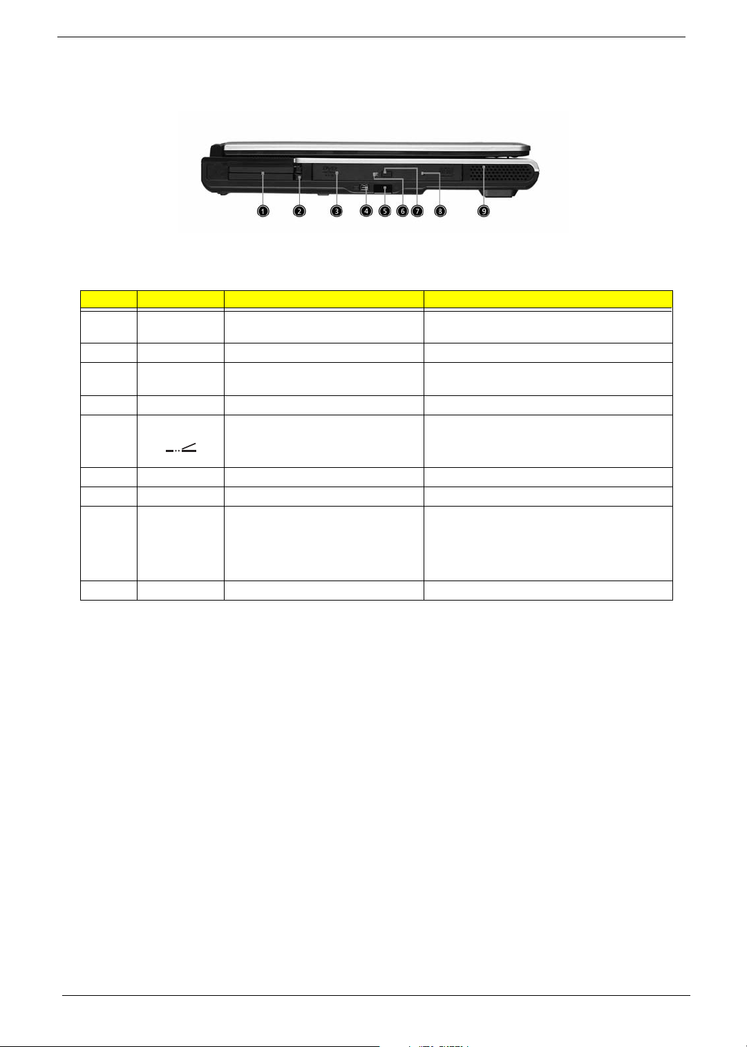
Left view
# Icon Item/ Port Description
1 PC Card slots Supports two Type II or one Type III CardBus PC
2 Eject button Eject PC cards from the card slots.
3 Optical drive Internal optical drive; accepts CDs or DVDs
4 IEEE 1394 port Connects to IEEE 1394 devices.
5 Infrared port Interfaces with infrared devices (e.g., infrared
Card(s).
depending on the optical drive type.
printer, IR-aware computer).
6 LED indicator Lights up when the optical drive is active.
7 Eject button Ejects the optical drive tray from the drive.
8 Emergency eject slot Ejects the optical drive tray when the computer is
9 Speaker Delivers stereo audio output.
turned off. There is a mechancial eject button on
the CD-ROM or DVD-ROM drive. Simply insert
the tip of a pen or paperclip and push to eject the
tray.
Chapter 1 7
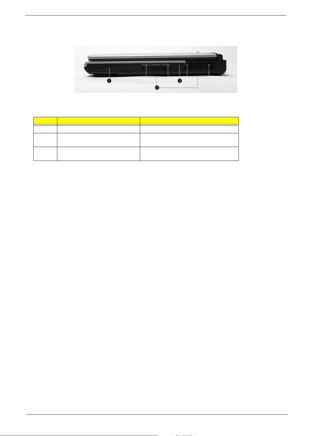
Right View
# Item/ Port Description
1 Speaker Delivers stereo audio output.
2 Ventilation slots Enable the computer to stay cool, even after
prolonged use.
3 Security keylock Connects to a Kensington-compatible
computer security lock.
8 Chapter 1
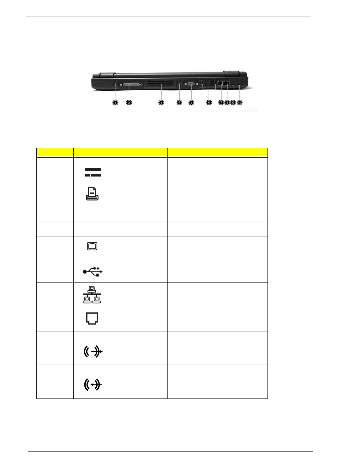
Rear Panel
l
# Icon Port Description
1 Power Jack Connects to an AC adapter
2 Parallel port Connects to a parallel device (e.g., parallel
3 Ventilation slots Enable the computer to stay cool, even
4 S-video port Connects to a television or display device
5 External display port Connects to a display device (e.g., external
6 Four USB 2.0 ports Connects to any Universal Serial Bus
7 Network jack Connects to an Ethernet LAN network
8 Modem jack Connects to the phone line
9 Speaker/line-out/
headphone jack
printer)
after prolonged use.
with S-video input.
monitor, LCD projector).
devices(e.g., USB mouse, USB camera).
Connects to audio line-out devices (e.g.,
speakers and headphones).
10 Line-in/mic-in jack Accepts audio line-in devices (e.g., audio
CD player and stereo walkman).
Chapter 1 9
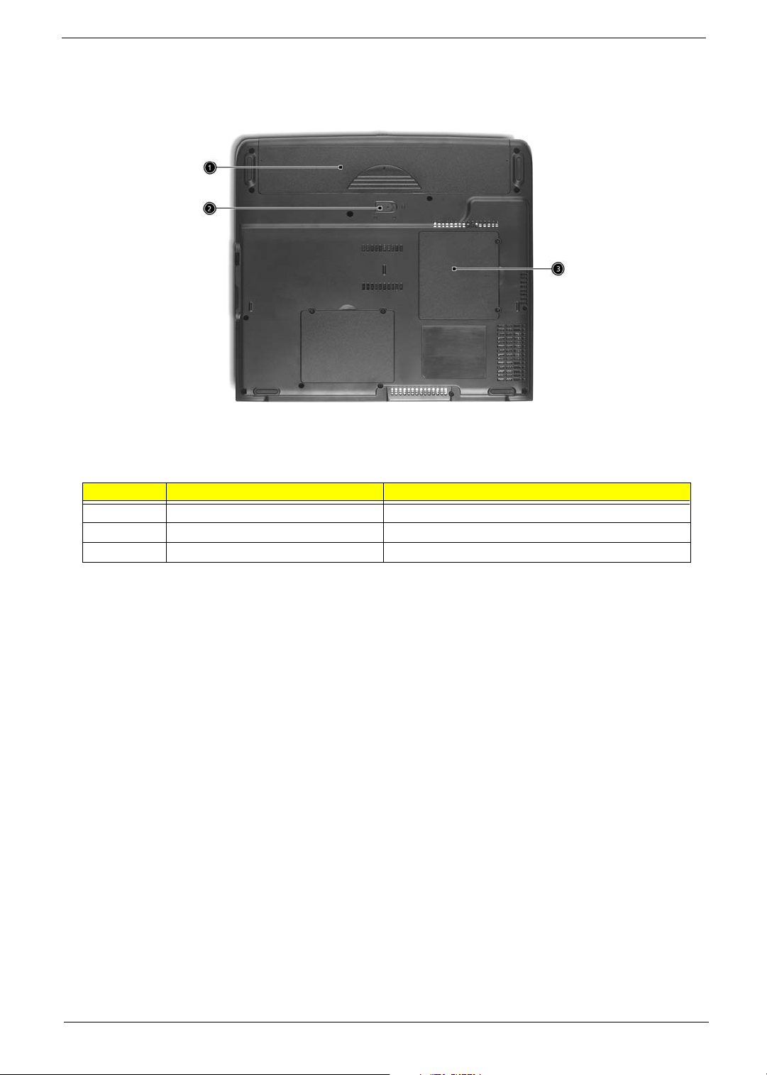
Bottom View
# Item Description
1 Battery bay Houses the computer’s battery pack.
2 Battery release latch Unlatches the battery to remove the battery pack.
3 Memory compartment Houses the computer’s main memory.
10 Chapter 1
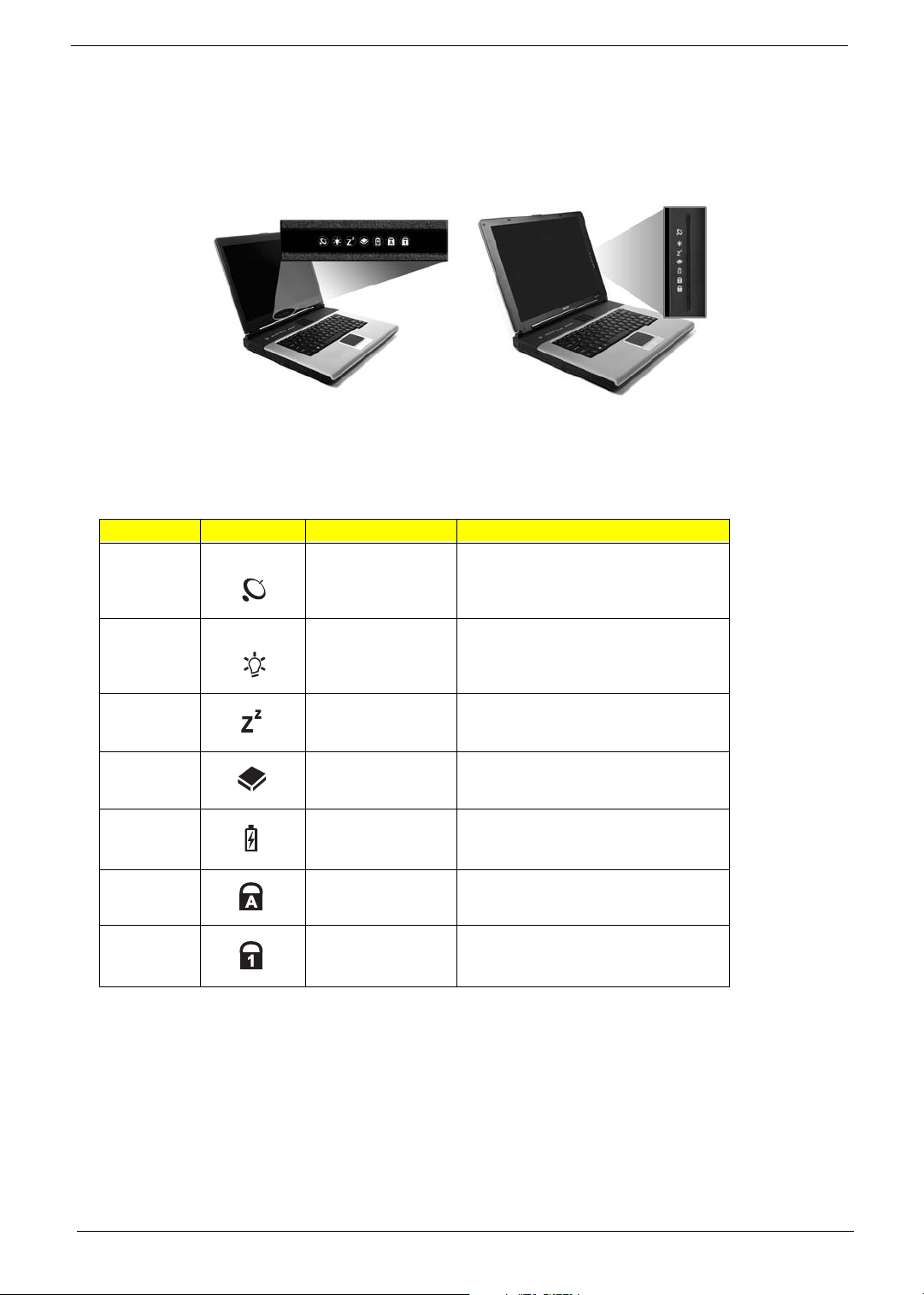
Indicators
The computer provides an array of seven indicators located below the display screen, showing the status of
the computer and its components.
The Power and Sleep status icons are visible even when you close the display cover so you can see the status
of the computer while the cover is closed.
# Icon Function Description
InviLink Indicates status of wireless or Bluetooth
(optional) communications.
Orange--WLAN; Blue--Bluetooth
1 Power Lights when the computer is on.
2 Sleep Lights when the computer enters Standby
3 Media Activity Lights when the floppy drive, hard disk or
4 Battery Charge Lights when the battery is being charged.
5 Caps Lock Lights when Caps Lock is activated.
6 Num Lock Lights when Numeric Lock is activated.
mode and blinks when it enters into or
resumes from hibernation mode.
optical drive is active.
Chapter 1 11
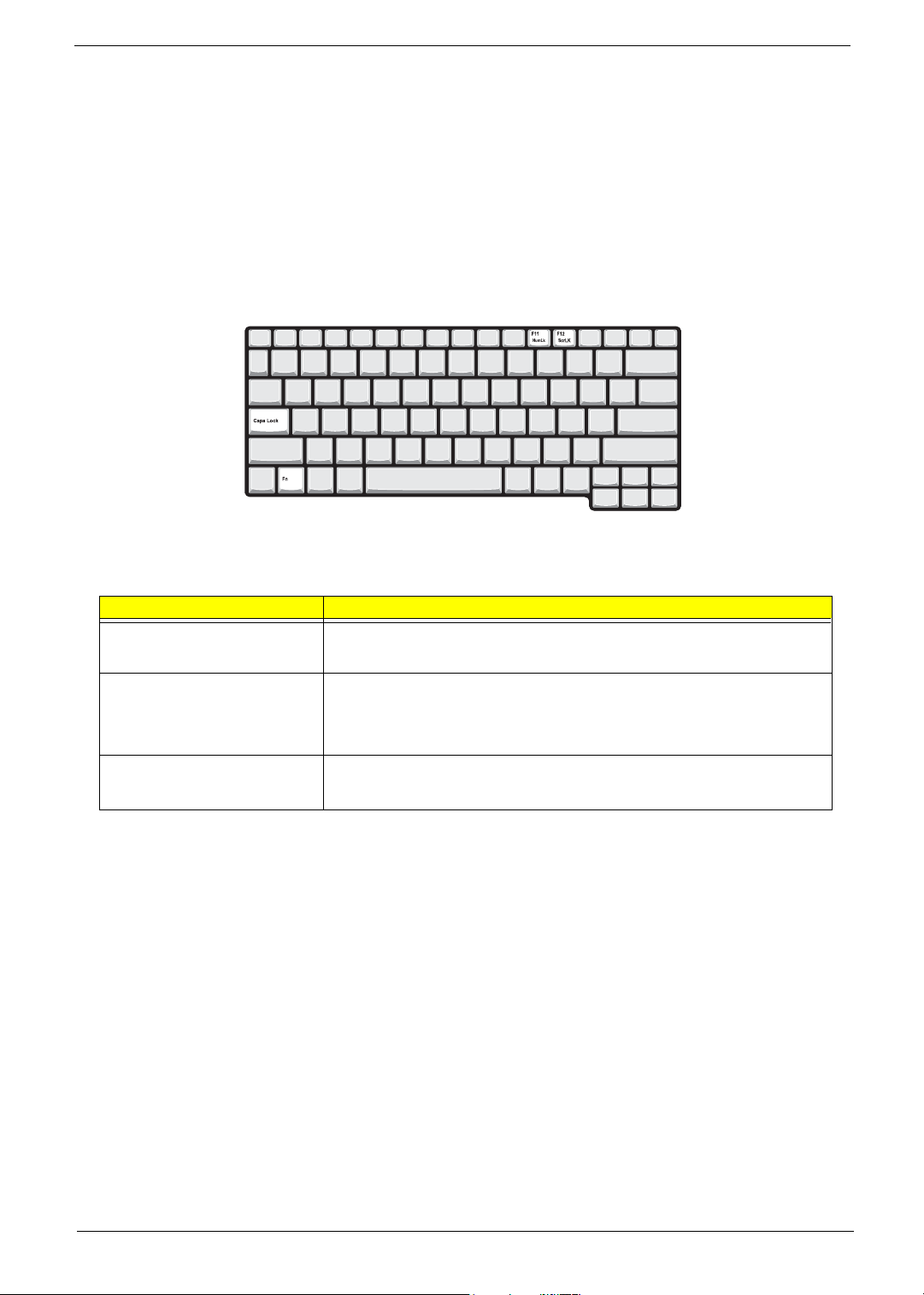
Key bo ar d
The keyboard has full-sized keys and an embedded keypad, separate cursor keys, two Windows keys and
twelve function keys.
Special keys
Lock keys
The keyboard has three lock keys which you can toggle on and off.
Lock key Description
Caps Lock
@
Num Lock (Fn-F11)
]
Scroll Lock (Fn-F12)
[
When @is on, all alphabetic characters typed are in uppercase.
When ] is on, the embedded keypad is in numeric mode. The keys function
as a calculator (complete with the arithmetic operators ), -, *, and /). Use this mode
when you need to do a lot of numeric data entry. A better solution would be to
connect an external keypad.
When [ is on, the screen moves one line up or down when you press the up
or down arrow keys respectively.
[ does not work with some applications.
12 Chapter 1
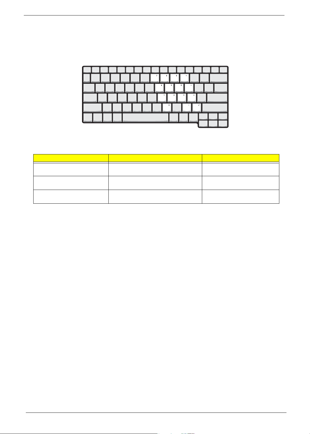
Embedded numeric keypad
The embedded numeric keypad functions like a desktop numeric keypad. It is indicated by small characters
located on the upper right corner of the keycaps. To simplify the keyboard legend, cursor-control key symbols
are not printed on the keys.
Desired access Num lock on Num lock off
Number keys on embedded
keypad
Cursor-control keys on embedded
keypad
Main keyboard keys Hold Fn while typing letters on embedded
Type numbers using embedded keypad in a
normal manner.
Hold Shift while using cursor-control keys. Hold Fn while using cursor-control
keys.
Type the letters in a normal manner.
keypad.
Chapter 1 13
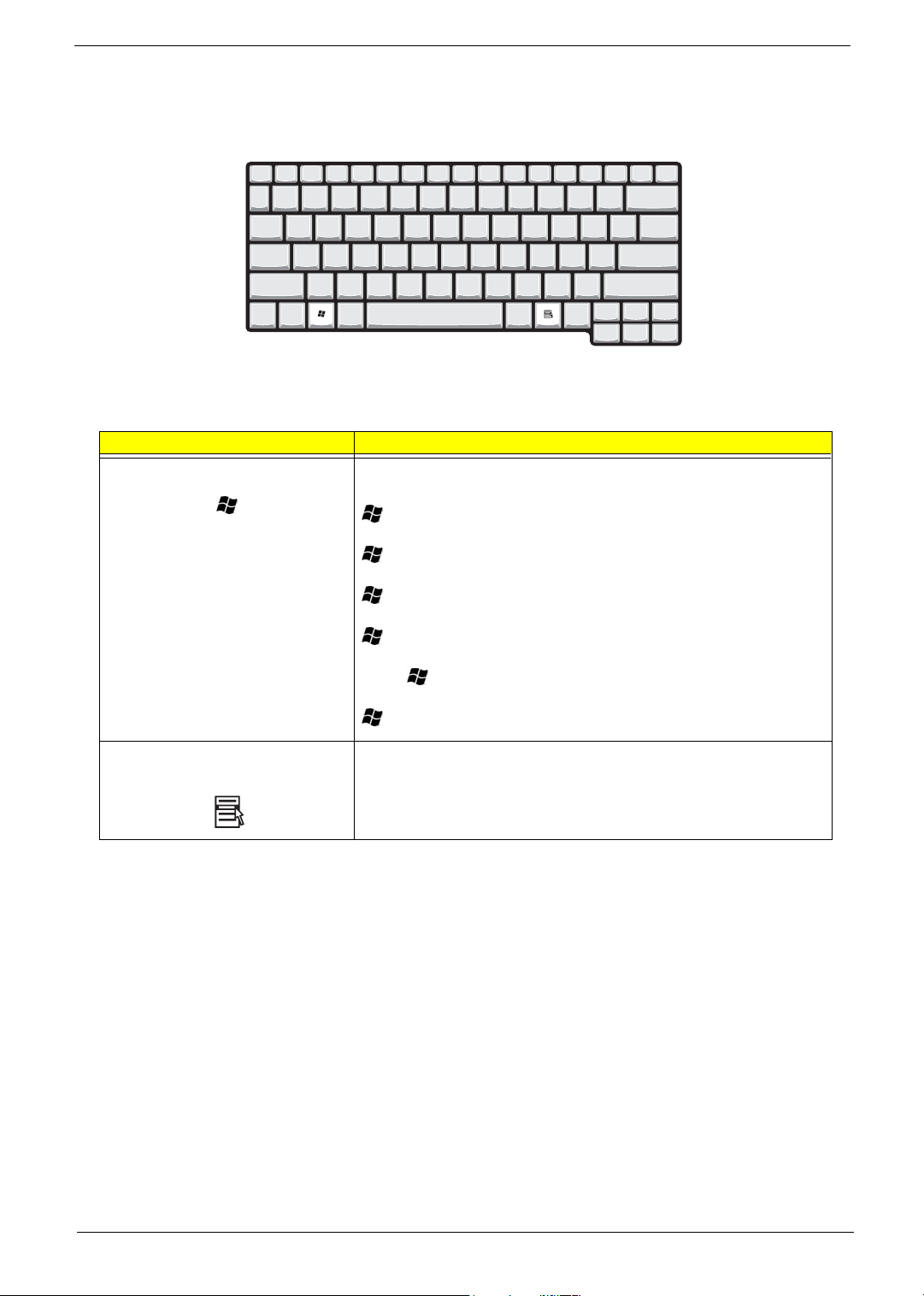
Windows keys
The keyboard has two keys that perform Windows-specific functions.
Keys Description
Windows logo key
Start button. Combinations with this key perform shortcut functions. Below
are a few examples:
+ Tab (Activates next taskbar button)
+ E (Explores My Computer)
+ F (Finds Document)
+ M (Minimizes All)
j+ + M (Undoes Minimize All)
+ R (Displays the Run... dialog box)
Application key Opens a context menu (same as a right-click).
14 Chapter 1
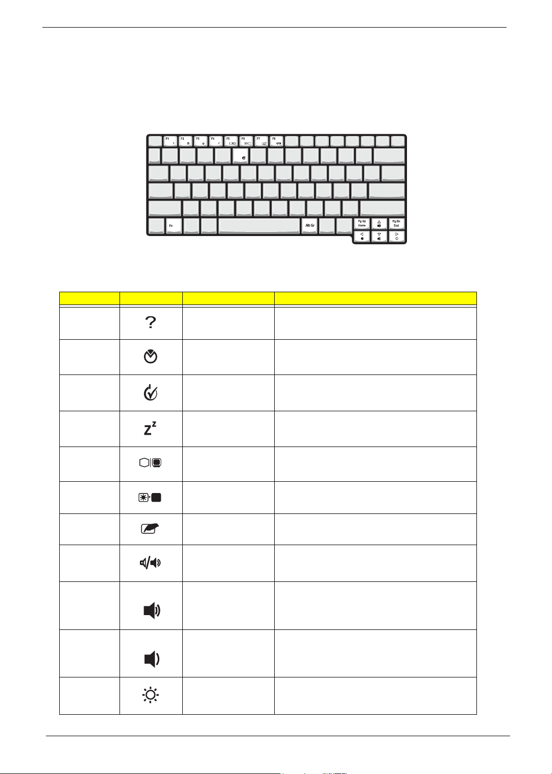
Hot Keys
The computer employs hot keys or key combinations to access most of the computer’s controls like screen
contrast and brightness, volume output and the BIOS Utility.
To activate hot keys, press and hold the Fn key before pressing the other key in the hot key combination.
Hot Key Icon Function Description
Fn-
l
Hotkey help Displays a list of the hotkeys and their functions.
Fn-
Fn-
Fn-
Fn-
Fn-
Fn-
Fn-
Fn-
Fn-
m
n
o
p
q
r
s
w
y
Setup Accesses the notebook configuration utility.
Power Management
Scheme Toggle
Sleep Puts the computer in Sleep mode.
Display toggle Switches display output between the display screen,
Screen blank Turns the display screen backlight off to save power.
Touchpad toggle Turns the internal touchpad on and off.
Speaker toggle Turns the speakers on and off; mutes the sound.
Volume up Increases the sound volume.
Volume down Decreases the sound volume.
Switches the power management scheme used by the
computer (function available if supported by operating
system).
external monitor (if connected) and both the display
screen and external monitor.
Press any key to return.
Fn-
x
Chapter 1 15
Brightness up Increases the screen brightness.
Hot Key Icon Function Description
Fn-
¨
z
Brightness down Decreases the screen brightness.
{
Fn-
}
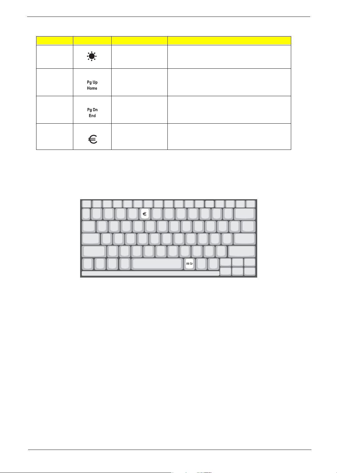
Fn-
aGr-Euro
The Euro symbol
If your keyboard layout is set to United States-International or United Kingdom or if you have a keyboard with a
European layout, you can type the Euro symbol on your keyboard.
Home
End
Euro Types the Euro symbol.
Functions as the
Functions as the
g key.
d key.
NOTE: for US keyboard users: The keyboard layout is set when you first set up Windows. For the Euro
symbol to work, the keyboard layout has to be set to United States-international.
To verify the keyboard type:
1. Click on Start, Control Panel.
2. Double-click on Regional and Language Options.
3. Click on the Language tab and click on Details.
4. Verify that the keyboard layout used for “En English (United States) is set to United States-International.
If not, select and click on ADD; then select United States-International and click on OK.
5. Click on OK.
To type the Euro symbol:
1. Locate the Euro symbol on your keyboard.
2. Open a text editor or word processor.
3. Hold
16 Chapter 1
aGr and press the Euro symbol.
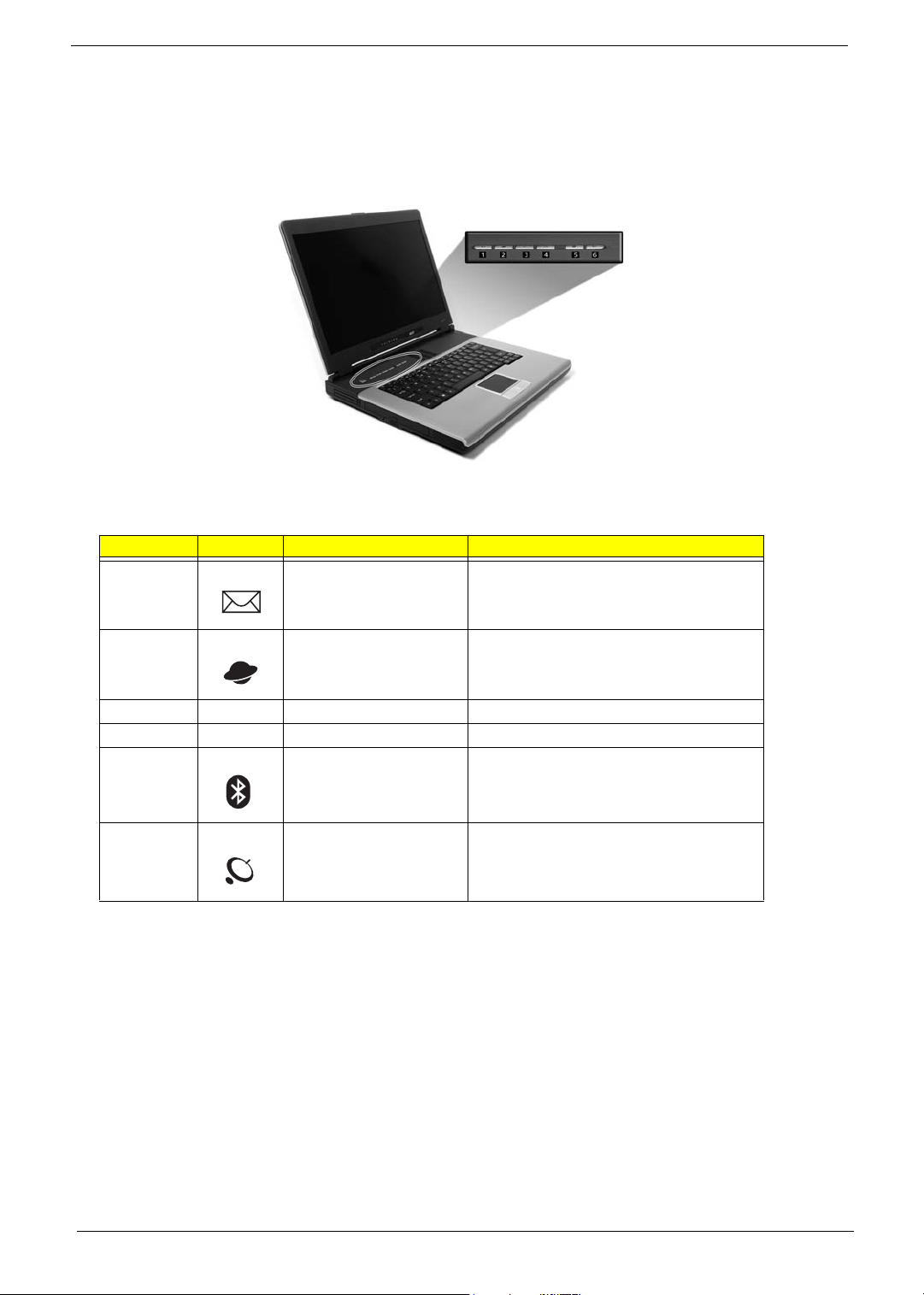
Launch Keys
Located at the top of the keyboard are six buttons. These buttons are called lauch keys. They are designated
as mail button, Web browser button, P1, P2, Bluetooth and Wireless buttons. The Wireless and Bluetooth
buttons cannot be set by the user. To set the other four launch keys, run the Acer Launch Manager.
# Icon Function Description
1 Mail Launches email application
2 Web browser Launches Internet browser application
3 e User-programmable
4 P User-programmable
5 Bluetooth (optional) Enables your Bluetooth
6 Wireless (optional) Enables your 802.11b/g Wireless LAN.
Chapter 1 17
Hardware Specifications and Configurations
System Board Major Chips
Item Controller
System core logic VIA K8N800+VIA VT8235CE
Super I/O controller NS PC87392
Audio controller VIA VT1612A
Video controller
Hard disk drive controller Embedded in VT8235CE
Keyboard controller Mitsubish LPC keyboard controller M38857
CardBus Controller TI PCI 7420
RTC Embedded in VT8235CE
LAN Controller/Chipset 10/100: VIA 6103L; Giga LAN: Realtek 8110SB-32
Memory Controller Built-in CPU
Bluetooth Controller/Chipset (Does this
chipset support voice function??)
Modem Controller/Chipset
HDD Controller Embedded in VT8235CE
ODD Controller Embedded in VT8235CE
Parallel Port Controller NS PC87392
USB Controller Embedded in VT8235CE
PCMCIA Controller TI PCI 7420
NVIDIA
NVIDIA
®
GeForceTM FX Go5200 for Aspire 1360 Series
®
GeForceTM FX Go5700 for Aspire 1520 Series
Processor
Item Specification
CPU type Mobile AMD Sempron processor 2600+ to 3000+ or higher (for Aspire 1360)
AMD Athlon 64 processor 3000+ to 3400+ or higher (for Aspire 1520)
CPU package uOG uOG 754 pin
CPU core voltage 1.5V
CPU I/O voltage High speed: 1.2V => for RAM 2.5V
Low speed: 1.2V =>for Hypertransport 1.2V
BIOS
Item Specification
BIOS vendor Phoenix BIOS
BIOS Version 1.0
BIOS ROM type Flash ROM
BIOS ROM size 512KB
BIOS package 32 Pin PLCC
Supported protocols ACPI 2.0, SMBIOS 2.3, PCI 2.3, Boot Block, PXE 2.0, Mobile PC2001,
BIOS password control Set by switch, see SW1 settings on chapter 5
Hard Disk Password, INT 13h Extensions, PCI Bus Power Management
interface Specification, EI Torito-Bootable CD-ROM Format Specification
V1.0, Simple Boot Flag 1.0
18 Chapter 1
Second Level Cache
Item Specification
Cache controller Built-in CPU
Cache size 128KB or 256KB for AMD Sempron CPU
1MB for AMD Athlon 64 DTR CPU
1st level cache control Always Enabled
2nd level cache control Always Enabled
Cache scheme control Fixed-in write back
System Memory
Item Specification
Memory controller VIA K8N800
Onboard memory size 0MB
DIMM socket number 2 Sockets
Supports memory size per socket 256/512/1024MB (if available)
Supports maximum memory size 2048MB (Please confirm if 1024MB has passed the test or not)
Supports DIMM type DDR-DRAM
Supports DIMM Speed 333 MHz
Supports DIMM voltage 2.5 V
Supports DIMM package 200-pin so-DIMM
Memory module combinations You can install memory modules in any combinations as long as they
match the above specifications.
Memory Combinations
Slot 1 Slot 2 Tota l Memory
0MB 128MB 128 MB
128MB 0MB 128 MB
128MB 128MB 256 MB
256MB 0MB 256MB
0MB 256MB 256MB
256MB 128MB 384MB
128MB 256MB 384MB
256MB 256MB 512MB
0MB 512MB 512MB
512MB 128MB 640MB
256MB 512MB 768MB
128MB 512MB 640MB
512MB 256MB 768MB
256MB 128MB 384MB
512MB 512MB 1024MB
Above table lists some system memory configurations. You may combine DIMMs with various capacities to
form other combinations.
LAN Interface
Item Specification
Chipset 10/100Mbps: VIA 6103L; Giga LAN: 8110SB-32
Chapter 1 19
LAN Interface
Item Specification
Supports LAN protocol 10/100Mbps for Aspire 1360; 10/100/1000Mbps for Aspire 1520
LAN connector type RJ45
LAN connector location Rear side
PXE Version 2.0
Modem Interface
Item Specification
Chipset VIA VT8235CE
Fax modem data baud rate (bps) 14.4K
Data modem data baud rate (bps) 56K
Supports modem protocol V.90/V.92MDC
Modem connector type RJ11
Modem connector location Rear side
.
Hard Disk Drive Interface
Item
Vendor & Model
Name
Capacity (MB) 30000 40000 60000
Bytes per sector 512 512 512
Logical heads 16 16 16
Logical sectors 63 63 63
Drive Format
Logical cylinders 16383 16383 16383
Physical read/write
heads
Disks 1/Not show/1 1/Not show/1/1 2
Spindle speed (RPM) 4200RPM 4200RPM 4200RPM
Performance Specifications
Buffer size 2MB 2MB/8MB for Toshiba 2MB/8MB for HGST
Interface ATA-5 for other vendors /ATA-
Data transfer rate
(disk-buffer, Mbytes/
s)
Data transfer, rate
(host~buffer, Mbytes/
s)
DC Power Requirements
Voltage tolerance 5 +/- 5% 5 +/- 5% 5 +/- 5%
HGST Moraga
IC25N030ATMR04
Fujitsu V-40 MHT2030AT
Seagate N1 ST93015A
2/Not show/2 2/Not show/2/2 3/4
6 for HGST and Toshiba
350 350 350
100 MB/Sec 100 MB/Sec 100MB/Sec
HGST Moraga
IC25N040ATMR04-
TOSHIBA Pluto 40G
MK4025GAS
Fujitsu V40+ MHT2040AT
Seagate N1 ST94019A
ATA-5 for other vendors /ATA6 for HGST
HGST Moraga
IC25N060ATMR04-0
TOSHIBA Neptune
MK6021GAS
ATA- 5 /ATA-6 f o r HGST
20 Chapter 1
CD-ROM Interface
Items Specification
Vendor & Model Name QSI SCR242
Mitsumi SR244W1
Performance Specification
Brust Data Transfer rate PIO mode 4:
16.7 MB/sec Max. (Mode 0~4)
Multi-word DMA mode 2:
16.7 MB/sec Max. (Mode 0~2)
Ultra DMA mode 2:
33.3MB/sec Max.
Access time (typ.) QSI-
Random: 90 ms
Full Stroke: 180 ms
Mitsumi-
Random: 100 ms
Full Stroke: 240 ms
Rotation speed 5100 rpm for QSI
5400 rpm for Mitsumi 24X CAV mode
Data Buffer Capacity 128 KB (built-in)
Interface Compliant to ATA/ATAPI-6
Applicable disc format QSI:
CD-DA, CD-ROM Mode-1, CD-ROM/XA Mode-2, Form-1 and Mode-2 Form-2, CD-i
Ready, Video-CD (MPEG-1), Karaoke CD, Photo-CD, Enhanced CD, CD Plus, CD
Extra, i-trax CD, CD-Text, CD-R and CD-RW
Mitsumi:
CD-DA, CD-ROM (Mode 1 and Mode2) CD-ROM XA (Mode 2 Form 1 and Form2),
CD-I (Mode2 Form 1 and Form 2), CD-I Bridge (Photo CD, CD EXTRA), Enhanced
CD, CD-RW, CD-R, CD-TEXT
Loading mechanism Drawer with soft eject and emergency eject hole
Power Requirement
Input Voltage +5V[DC]+/-5%
DVD-ROM Interface
Item Specification
Vendor & model name MKE SR-8177
Performance Specification With CD Diskette With DVD Diskette
Transfer rate (KB/sec) Average Sustained:
CAV mode
775~1800 blocks/sec
(10.3X to 24X)
1550~3600kBytes/sec (Mode 1)
1768~4106 kBytes/sec (Mode 2)
DVD-5:
Normal Speed (1X) 11.08 Mbits/sec
CAV mode 36.67~88.64 Mbits/sec
DVD-9/DVD-R:
Normal Speed (1X) 11.08 Mbits/sec
CAV mode 36.67~88.64 Mbits/sec
Chapter 1 21
 Loading...