

Page 1

Machine Disassembly and Replacement
This chapter contains step-by-step procedures on how to disassemble the notebook computer for
maintenance and troubleshooting.
To disassemble the computer,you need the following tools:
❑ Wrist grounding strap and conductive mat for preventing electrostatic discharge
❑ plastic screw driver
❑ FPC fixture
❑ Tweezers
❑ Flat-bladed screw driver or plastic stick
❑ hex screw driver
❑ plastic tool that can prize stripe cover
NOTE: The screws for the different components vary in size. During the disassembly process, group the
screws with the corresponding components to avoid mismatch when putting back the components.
When you remove the stripe cover, please be careful not to scrape the cover.
Chapter 3
Chapter 3 51
Page 2

General Information
Before You Begin
Before proceeding with the disassembly procedure, make sure that you do the following:
1. Turn off the power to the system and all peripherals.
2. Unplug the AC adapter and all power and signal cables from the system.
3. Remove the battery pack.
NOTE: Aspire 1200 uses mylar or tape to fasten the FFC/FPC/connectors, you may need to tear the tape or
mylar before you disconnect different FFC/FPC/connectors.
52 Chapter 3
Page 3
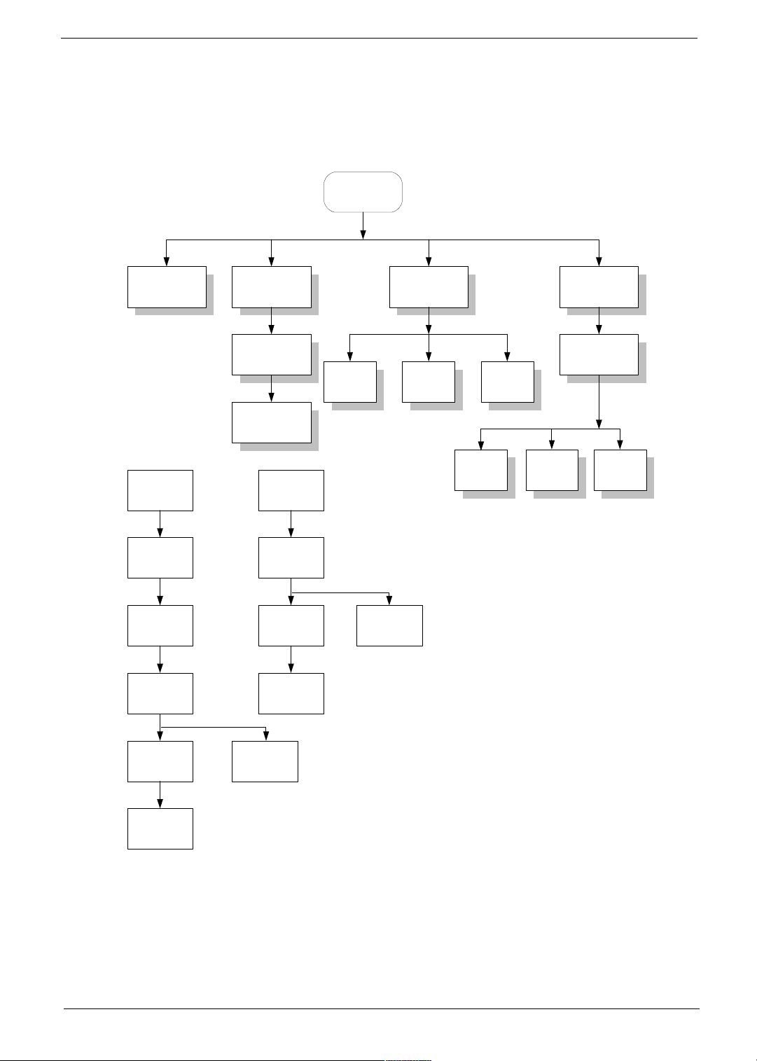
Disassembly Procedure Flowchart
The flowchartonthesucceedingpage gives you a graphic representationon the entire disassembly sequence
and instructs you on the components that need to be removed during servicing. For example, if you want to
remove the system board, you must first remove the keyboard, then disassemble the inside assembly frame in
that order.
Start
Ax2
Bx3
Battery HDD Module RAM Door
HDD
Connector
Thermal
Module
Module
HDD
15.0" LCD
Module
Fx4
LCD B ezel
LCD Latch
14.1" LCD
Module
Fx4
LCD Bezel
Fx2
Inverter
Board
Gx4
LCD FPC
RAM
Cx1
System
Window
DVDROM
Key-
board
Main Unit
(see next
page)
Bx2
Stripe C over
Dx2
Ex2
LCD
Module
LCD P anel
LCD FPC
Fx4
Hx2
LCD
Bracketsx2
Fx2
Inverter
Board
LCD
Bracketsx2
Chapter 3 53
Page 4
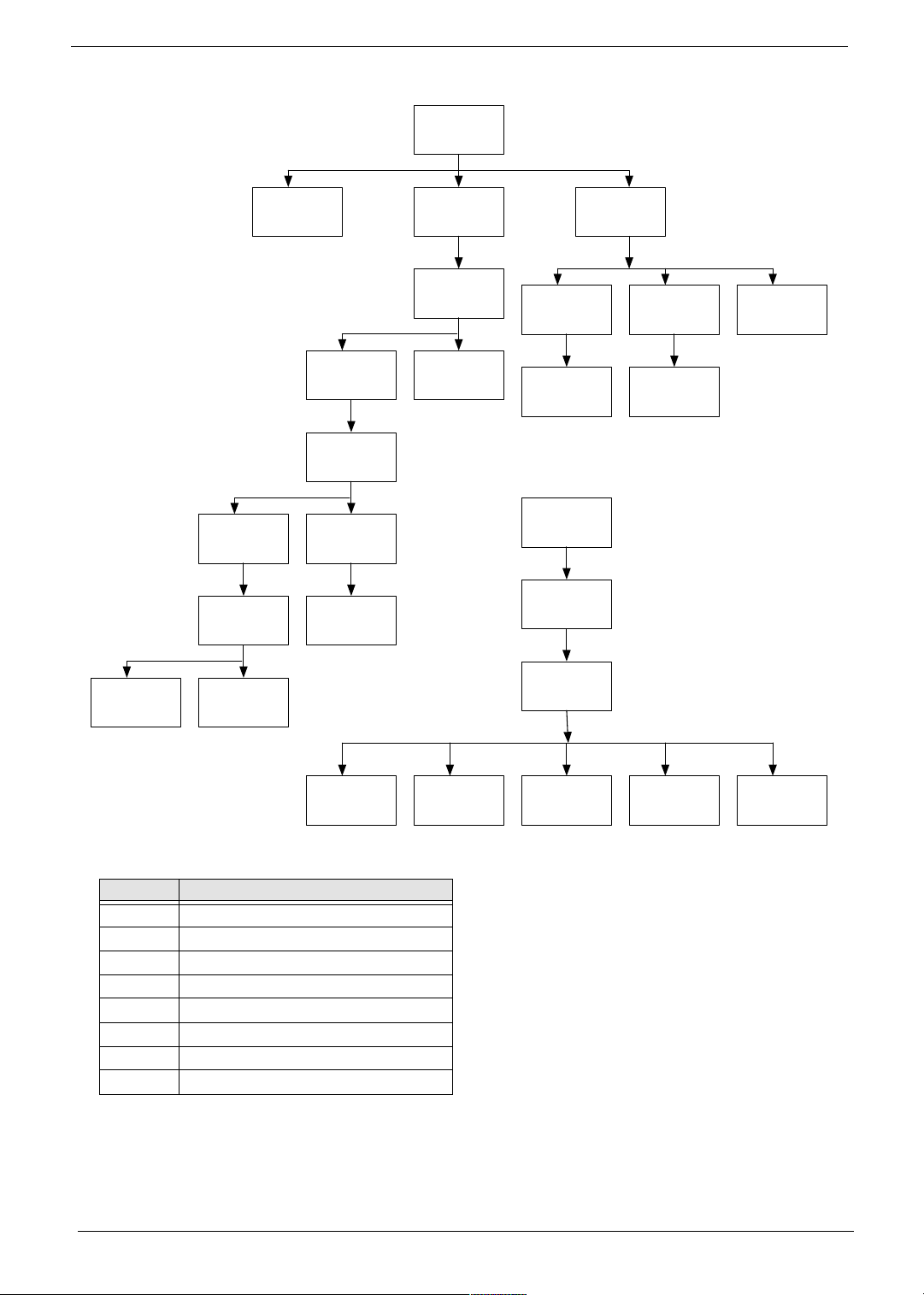
Main Unit
Touch Pad
Logic Lower
Upper
Shielding
Touchpad
Bracket
Switch
Board
(below)
Audio Board
FPC
Audio Board
Module
Audio Board
Shielding
Audio Board
Right/Left
Hinge
Saddles
Speakers
Stripe CoverLogic Upper
Keyboard
FFC
Keyboard
Logic Lower
Floppy Disk
Drive
Module
Main Board
System
Window
FFC
System
Window
LCD Module
Thermal
Support
DVD Carrier
System
Window
FPC
PCMCIA
Card
LAN/
Modem
Card
Screw List
Item Description
A Screw M2.5 X 0.45+8FD-ZK
B Screw M2.5 X 4.5P+3FP-ZK
C Screw M2.5 X 0.45P+4FP-NI(NL)
D Screw M2.5 X 0.45+8FP-NI(NL)
E Screw M2.5 X 0.45+18FP-ZK(NL)
F Screw M2.5 X 0.45P+5K-2K(NL)
G Screw M2.0 X 0.4P+2.3(NL)
H Screw M2.0 X 0.4P+3FP-ZK(NL)
54 Chapter 3
Page 5

Removing the Battery Pack
1. Press the battery lock.
2. Push the release button forward then remove the battery pack.
Chapter 3 55
Page 6

Removing the HDD Module/Thermal Module/CPU and DVD-ROM
1. Remove the two screws of the HDD module, then remove the HDD module from the logic lower.
2. Unscrew the three screws on the ram door.Then remove the ram door. Next, disconnect the thermal
connector. Then, remove the four screws on the thermal module and remove the thermal module.
3. Use the CPU fixture and the flat-bladed screw driver to remove the CPU.
4. Remove the screw on the DVD-ROM bracket and push the DVD-ROM bracket. Then remove this module.
56 Chapter 3
Page 7

Chapter 3 57
Page 8

Removing the LCD Module/the Keyboard and the System Window
Removing the LCD Module
1. Remove the two (one on each side) screws holding the LCD stripe cover. Then prize the stripe cover with
the plastic flat-bladed tool.
2. Unscrew the four screws (two on each side) holding the LCD module to the main unit. Then, Disconnect
LCD FPC and remove the LCD module.
Removing the keyboard
1. Remove the four (two on each side) screws holding the keyboard.
2. Disconnect the keyboard connector. After disconnect the keyboard connector then remove the keyboard.
Removing the system window
1. Disconnect system window FPC.
2. Unscrew the two screws holding the system window.Then remvoe the system window.
58 Chapter 3
Page 9

Disassembling the Main Unit
Separate the main unit into the logic upper and the logic lower assembly
1. Remove the four screw locks from I/O port.
2. Then remove the two screws as the picture shows.
3. Remove the eight screws on the logic lower.
4. Disconnect switch board FPC.
5. Remove the logic upper from the main unit.
Disassembling the logic upper
1. Unscrew the five screws holding the right and the left hinge saddles.
2. Remove the right and the left hinge saddles.
3. Tear the mylar from logic upper assembly.
4. Remove the two screws holding the audio board.
5. Remove the audio board shielding.
6. Disconnect audio board FPC
Chapter 3 59
Page 10

.
7. Remove the four screws holding the upper shielding.
8. Release the two locks.
9. Then remove the upper shielding from the logic upper assembly.
10. Disconnect the two speakers wires (one on each side).
11. Remove the two screws holding the speakers on each side. Then remove the speakers.
.
12. Disconnect touchpad FFC from the touch pad.
13. Remove the touchpad bracket as the pictures show. Please see the yellow arrows.
14. Remove the touchpad.
15. Disconnect the touchpad FFC and then remove it.
60 Chapter 3
Page 11

16. Remove the two screws that hold switchboard on the logic upper.One is on the right; the other is on the
left.
17. Disconnect the audio board FPC from the switchboard.
18. Disconnect the switchboard FPC.
19. These are complete steps for logic upper disassembly.
Disassembling the logic lower
1. Remove the two screws holding the floppy disk drive bracket.
2. Disconnect the floppy disk drive FFC.
3. Disconnect the system window FPC.
4. Remove the two screws holding the mainboard.
5. Then remove the mainboard carefully.
Chapter 3 61
Page 12

6. Unscrew the three screws that holds the DVD-ROM bracket.
7. Remove the DVD-ROM bracket.
8. Remove the four screws holding the thermal support.
9. Remove the thermal support.
10. Tear the tape on LAN/Modem card.
11. Disconnect the LAN/Modem card from mini PCD.
12. Disconnect LAN/Modem wires from the LAN/Modem card.
13. These are complete steps for logic lower disassembly.
62 Chapter 3
Page 13

Disassembling the LCD Module-15 Inch
1. First remove the two screw pads then remove the two screws.
2. Disattach the LCD bezel carefully. Please note that you have to push forward at the two indentations.
3. Unscrew the two screws then remove the latch.
4. Unscrew the two screws on the inverter board.
5. Remove the four screws holding the right and left hinges. There are two screws on each side.
6. Remove the right and the left hinge.
7. Dettach the EMI tape and then remove LCD from the cover carefully.
8. Disconnect the inverter board from LCD FPC.
9. Disconnect the LCD power connector.
10. Disconnect the LCD FPC.
11. Unscrew the eight screws on the brackets. There are four on each side then remove the brackets.
Chapter 3 63
Page 14

64 Chapter 3
Page 15

Disassembling the External Modules
Disassembling the HDD Module
1. Remove the four screws on HDD carrier.
2. Remove the hard disk drive from the carrier.
3. Disconnect the hard disk connector.
Disassembling the Floppy Disk Drive Module
1. Disconnect the floppy disk drive FFC.
2. Unscrew the two screw holding the bracket.
3. Unscrew the screw holding the bracket.
4. Remove the right and the left brakets.
5. Press the FDD latch with the fixture and remove the FDD panel.
.
Disassembling the DVD-ROM Module
1. Unscrew the two screws holding the support plate.
2. Then remove the support plate.
Chapter 3 65
Page 16

66 Chapter 3
 Loading...