

Page 1

Altos S700 Series
User’s Guide
Page 2

Copyright © 2002 Acer Incorporated
All Rights Reserved.
Altos S700 Series
User’s Guide
Changes may be made periodically to the information in this publication without obligation
to notify any person of such revision or changes. Such changes will be incorporated in new
editions of this manual or supplementary documents and publications. This company makes
no representations or warranties, either expressed or implied, with respect to the contents
hereof and specifically disclaims the implied warranties of merchantability or fitness for a
particular purpose.
Record the model number, serial number, purchase date, and place of purchase information in
the space provided below. The serial number and model number are recorded on the label
affixed to your computer. All correspondense concerning your unit should include the serial
number, model number, and purchase information.
No part of this publication may be reproduced, stored in a retrieval system, or transmitted, in
any form or by any means, electronic, mechanical, photocopy, recording, or otherwise,
without the prior written permission of Acer Incorporated.
Model Number : _________________________________
Serial Number: ___________________________________
Purchase Date: ___________________________________
Place of Purchase: ________________________________
Acer and the Acer logo are registered trademarks of Acer Inc. Other company’s product
names or trademarks are used herein for identification purposes only and belong to their
respective companies.
Page 3

Preface vii
Audience vii
Conventions Used In This User Guide vii
European Community Statement xv
Introduction 3
Features 4
Disk Drive Carrier 4
Power Supplies 4
Cooling System 5
I/O Option Modules 6
Safety Statements 13
Unpacking and Initial Setup 15
Installing the System in an Equipment Rack 16
Ambient Temperature 16
Air Flow 16
Mechanical Loading 16
Electrical Considerations 18
Circuit Overloading 18
Setting Fibre Channel Loop Speed (2Gb or 1Gb) 19
2Gb Operation 19
1Gb Operation 19
Split Fibre Channel Loop Operation (Quad Loop) 21
Setting Up Split Loop Operation 21
Removing Split Loop Operation 21
Configuration Rules 23
Supported Host Bus Adapters 24
Supported Cables 25
Copper Cables 25
Optical Cables 26
Setting the Enclosure ID 29
Configurations 32
JBOD Configurations 33
Dual FC Loop Configuration 33
Quad Loop Configuration 35
Connecting a Power Source 37
Connecting an AC Power Source 37
Disk Drive Spin Up Sequence 38
Altos S700 Series RAID Controller Introduction 41
RAID Controller Circuit Boards 43
Controller Circuit Board 43
I/O Circuit Board 43
RS232 Serial Port 44
RAID Controller Location 45
Contents
Page 4

RAID Controller Status LEDs 46
RAID Controller Configurations 47
Setting the Enclosure ID 48
Configurations 51
Single RAID Controller Configuration 51
Dual RAID Controller Configuration 54
Connecting a Power Source 57
Connecting an AC Power Source 57
Disk Drive Spin Up Sequence 58
Overview 61
LS Module 62
LS Module Features 62
Altos S700 Enclosure LEDs 63
Disk Drive LEDs 65
Power Supply LEDs 67
Advanced Cooling Module (ACM) LEDs 68
RAID Controller LEDs 69
Location of the Components 73
Installing and Removing a Disk Drive Carrier 74
Installing a Disk Drive Carrier 74
Removing a Disk Drive Carrier 74
Installing and Removing an LS Module 76
Installing an LS Module 76
Removing an LS Module 76
Installing and Removing a Power Supply 78
Installing a Power Supply 78
Removing a Power Supply 78
Installing and Removing an Advanced Cooling Module 79
Installing an Advanced Cooling Module 79
Removing an Advanced Cooling Module 79
Installing and Removing an I/O Module/RAID Controller 80
Installing an I/O Module/RAID Controller 80
Removing an I/O Module/RAID Controller 80
Caution: 82
Warning 88
Technical Specifications 90
Host Interface 90
Disk Drive Interface 90
System 90
Redundant, Hot Swappable Components 90
Physical Dimensions 90
Warranty 91
Monitoring 91
Failure Notification 91
Contentsiv
Page 5

Disk Drives 92
Power Supply 92
Temperature 92
Humidity 92
Altitude 92
Operational Shock 93
Operational Vibration 93
Regulatory Agency Compliance 93
Equipment and parts necessary for upgrade 103
Upgrading from JBOD to RAID 103
Installing the Battery Backup Unit 104
v
Page 6

Contentsvi
Page 7
vii
Preface
This Installation Guide describes the installation and operation of the
Altos S700 Series. The following products are covered: AS.S7001.001,
AS.S7001.002, AS.S7001.003, AS.S7001.004, AS.S7001.005,
AS.S7001.006.
Audience
This Installation Guide is intended for use by the person installing and
operating the Altos S700 Series. This Installation Guide describes the
operation of the Altos S700 Series only. For details relating to the host
system, refer to the documentation supplied with the host system.
Conventions Used In This User Guide
The following conventions are used throughout this Installation Guide.
A NOTE gives general information, such as helpful tips and
references to related information.
A CAUTION means take care. There is a risk of causing damage to
the equipment or losing data.
A WARNING means beware. There is a risk of electric shock
or personal injury. Before working on the enclosure be
aware of the hazards that exist.
Page 8

viii
Notices
FCC notice
This device has been tested and found to comply with the limits for a Class B
digital device pursuant to Part 15 of the FCC Rules. These limits are designed to
provide reasonable protection against harmful interference in a residential
installation. This device generates, uses, and can radiate radio frequency
energy, and if not installed and used in accordance with the instructions, may
cause harmful interference to radio communications.
However, there is no guarantee that interference will not occur in a particular
installation. If this device does cause harmful interference to radio or television
reception, which can be determined by turning the device off and on, the user
is encouraged to try to correct the interference by one or more of the following
measures:
• Reorient or relocate the receiving antenna
• Increase the separation between the device and receiver
• Connect the device into an outlet on a circuit different from that to which
the receiver is connected
• Consult the dealer or an experienced radio/television technician for help
Notice: Shield cables
All connections to other computing devices must be made using shielded cables
to maintain compliance with FCC regulations.
Notice: Peripheral devices
Only peripherals (input/output devices, terminals, printers, etc.) certified to
comply with the Class B limits may be attached to this equipment. Operation
with noncertified peripherals is likely to result in interference to radio and TV
reception.
Caution! Changes or modifications not expressly approved by
the manufacturer could void the user’s authority, which is granted
by the Federal Communications Commission, to operate this
computer.
Page 9

Use conditions
This part complies with Part 15 of the FCC Rules. Operation is subject to the
following two conditions: (1) this device may not cause harmful interference,
and (2) this device must accept any interference received, including interference
that may cause undesired operation.
Notice: Canadian users
This Class B digital apparatus meets all requirements of the Canadian
Interference-Causing Equipment Regulations.
Remarque à l’intention des utilisateurs canadiens
Cet appareil numérique de la classe B respected toutes les exigences du
Règlement sur le matériel brouilleur du Canada
.
ix
Page 10

x
Important safety information
Only a technically qualified person shall access, integrate, configure, and service
this product.
Intended application uses
This product was evaluated as Information Technology Equipment (ITE), which
may be installed in offices, schools, computer rooms, and similar commercial
type locations. The suitability of this product for other Product Categories and
Environments (such as medical, industrial, alarm systems, and test equipment),
other than an ITE application, may require further evaluation.
Checking the power cords
Warning! To avoid electrical shock, do not attempt to
modify or use the supplied AC power cord(s), if they are
not the exact type required.
If a power cord(s) supplied is not compatible with the AC wall outlet in your
region, get one that meets the following criteria:
• The power cord must be properly rated for the AC voltage in your region.
• The power cord plug cap must have an electrical current rating that is at
least 125% of the electrical current rating of the product.
• The power cord plug cap that plugs into the wall socket-outlet must have a
grounding-type male plug designed for use in your region.
• The power cord must have safety certifications for your region, and shall
be marked with the certification markings.
• The power cord plug cap that plugs into the AC receptacle on the power
supply must be an IEC 320, sheet C13, type female connector.
• In Europe, the power cord must be less than 4.5 meters (14.76 feet) long,
and it must be flexible <HAR> (harmonized) or VDE certified cordage to
comply with the chassis' safety certifications.
• The power supply cord(s) is the main disconnect device to AC power. The
socket outlet(s) shall be near the equipment and shall be readily accessible
for disconnection.
Page 11

Multiple power cords
Warning! To avoid electrical shock, disconnect all AC power cords before
accessing inside the system.
Earth grounded socket-outlets
Warning! To avoid electrical shock, the system power cord(s) must be plugged
into socket-outlet(s) that is provided with a suitable earth ground.
Precautionary reminders
• Over current protection
The system is designed to operate on a 20A AC voltage source that is
provided with 20A over current protection. If the AC source for the rack
exceeds 20A over current protection, each system must be provided with
20A or less over current supplemental protection. The supplementary over
current protection must have the appropriate regional safety certifications
for the over current application.
• Power supply modules
Power supply modules have double-pole/neutral fusing.
• Ventilation considerations
The equipment rack must provide sufficient airflow to the front of the
system to maintain proper cooling. The rack selected and the ventilation
provided must be suitable to the environment in which the system will be
used.
•Fans
To avoid injury do not touch moving fan blades.
• Cooling and airflow
For proper cooling and airflow, always install all access covers before
turning on the system. Operating the system for longer than five minutes
without the covers in place can cause overheating and damage to system
components.
• Temperature limits
• The operating temperature of the system, when installed in the rack, must
not go below 10 °C (50 °F) or rise above 35 °C (95 °F). Extreme fluctuations
in temperature may cause a variety of problems in system, and safety limits
may be broken.
• Lifting and Moving
Do not attempt to lift or move the server by the handles on the power
supplies.
xi
Page 12

xii
Equipment rack precautions
Follow the rack manufacturer's safety and installation instructions for proper
rack installation.
The following additional rack safety installation measures shall be considered:
• Anchor the equipment rack
The equipment rack must be anchored to an unmovable suitable support
to prevent the rack from falling over when one or more systems are fully
extended out of the rack assembly. You must also consider the weight of
any other devices installed in the rack assembly. The equipment rack must
be installed according to the manufacturer's instructions.
• Main AC power disconnect
You are responsible for installing an AC power disconnect for the entire
rack unit. This main disconnect must be readily accessible, and it must be
labeled as controlling power to the entire unit, not just to the system(s).
• Grounding the rack installation
To avoid the potential for an electrical shock hazard, the rack assembly
itself must be suitably earth grounded, according to your local regional
electrical codes. This typically will require the rack to have its own separate
earth ground. We recommend you consult your local approved electrician.
Page 13

xiii
Important safety instructions
Read these instructions carefully. Save these instructions for future reference.
1 Follow all warnings and instructions marked on the product.
2 Unplug this product from the wall outlet before cleaning. Do not use
liquid cleaners or aerosol cleaners. Use a damp cloth for cleaning.
3 Do not use this product near water.
4 Do not place this product on an unstable cart, stand, or table. The product
may fall, causing serious damage to the product.
5 Slots and openings in the cabinet and the back or bottom are provided for
ventilation; to ensure reliable operation of the product and to protect it
from overheating, these openings must not be blocked or covered. The
openings should never be blocked by placing the product on a bed, sofa,
rug, or other similar surface. This product should never be placed near or
over a radiator or heat register, or in a built-in installation unless proper
ventilation is provided.
6 This product should be operated from the type of power indicated on the
marking label. If you are not sure of the type of power available, consult
your dealer or local power company.
7 Do not allow anything to rest on the power cord. Do not locate this
product where persons will walk on the cord.
8 If an extension cord is used with this product, make sure that the total
ampere rating of the equipment plugged into the extension cord does not
exceed the extension cord ampere rating. Also, make sure that the total
rating of all products plugged into the wall outlet does not exceed the fuse
rating.
9 Never push objects of any kind into this product through cabinet slots as
they may touch dangerous voltage points or short out parts that could
result in a fire or electric shock. Never spill liquid of any kind on the
product.
10 Do not attempt to service this product yourself, as opening or removing
covers may expose you to dangerous voltage points or other risks. Refer all
servicing to qualified service personnel.
11 Unplug this product from the wall outlet and refer servicing to qualified
service personnel under the following conditions:
a When the power cord or plug is damaged or frayed
b If liquid has been spilled into the product
c If the product has been exposed to rain or water
Page 14

xiv
d If the product does not operate normally when the operating
instructions are followed. Adjust only those controls that are covered
by the operating instructions since improper adjustment of other
controls may result in damage and will often require extensive work
by a qualified technician to restore the product to normal condition.
e If the product has been dropped or the cabinet has been damaged
f If the product exhibits a distinct change in performance, indicating a
need for service.
12 Replace the battery with the same type as the product's battery we
recommend. Use of another battery may present a risk of fire or explosion.
Refer battery replacement to a qualified serviceman.
13 Warning! Batteries may explode if not handled properly. Do not
disassemble or dispose of them in fire. Keep them away from children and
dispose of used batteries promptly. Dispose of used batteries according to
manufacturer's instructions.
14 Use only the proper type of power supply cord set (provided in your
accessories box) for this unit. It should be a detachable type: UL listed/CSA
certified, type SPT-2, rated 7A 125V minimum, VDE approved or its
equivalent. Maximum length is 15 feet (4.6 meters).
Page 15

European Community Statement
This equipment complies with the following European directives:
EMC Directive 89/336/EEC and amending Directives 92/31/EEC and 93/
68/EEC Low Voltage Directive 73/23/EEC.
xv
Page 16

xvi
Page 17

Chapter 1
Introduction
Page 18

This Chapter introduces the Altos S700 Series. The main
features of the Series are described along with a list of the
models that are available.
Page 19

Introduction
The Altos S700 Series provides a highly flexible, high performance
storage solution that evolves to meet your changing needs. Based on a
modular, “building block” enclosure design, the Altos S700 Series
offers exceptional scalability. Each enclosure supports up to 14 disk
drives, in a dense 3U form factor. As your storage needs grow, simply
add Altos S700 enclosures dynamically - up to a total of 8 enclosures.
The Altos S700 Series can be scaled in multiple dimensions, enabling
flexible configuration of capacity, performance and functionality, to
match and grow with virtually any application or IT environment. The
enclosure is available with your choice of copper, or optical I/O
modules, with RAID Controller option, and is downward compatible to
1Gbps, protecting your investment. A high performance, industry first
Quad Loop
700 MB/s from a single enclosure. 2Gb Fibre Channel connectivity
provides simplified cabling and extremely high bandwidth, for
outstanding performance in demanding applications.
1
(4 FCAL loops on one enclosure) capability provides over
1
Quad Loop functionality is only available on JBOD systems.
3
Page 20

Chapter 1 Introduction4
Features
• Redundant data paths with dual-ported fibre drives and dual
(200MB/s) fibre channel loops for a total of 400 MB/s.
• Quad Loop feature, provides over 700MB/s from a single enclosure.
• RAID controller option to give RAID functionality.
• Downward compatible to 1Gbps.
• Dense enclosure with 14 drives in a 3U form factor.
• Scalable to 112 drives, support for 15K rpm drives.
• Enhanced enclosure services (SES) monitoring and reporting.
• No single point of failure, with redundant, hot-swappable
components.
• Intuitive, comprehensive management with Spheras Storage
Manager.
• User installable, configurable and on-line maintainable.
• Industry-standard 19-inch rackmount or deskside configuration.
• Dual AC power supplies.
Disk Drive Carrier
The disk drive carrier supports one inch, SCA-2 direct attach disk drives.
The Altos S700 Series can hold up to fourteen disk drive carriers. The
disk drives can be hot swapped and the disk drive carriers provide for
blind mating.
Power Supplies
The Altos S700 Series uses two AC power supplies for normal
operation, providing redundancy of the power system. The power
supplies can be hot swapped. The AC power supplies provide 673 Watts
continuous output power and 853 Watts peak output power. The
power supplies provide active current sharing, power factor correction,
over current and over voltage protection is also provided. The power
supplies have individual power inputs.
Page 21
5
Caution: Power supply cords shall have conductors with a crosssectional area not less than 4mm
corresponds to a minimum 10AWG wire.
2
. This cross-sectional area
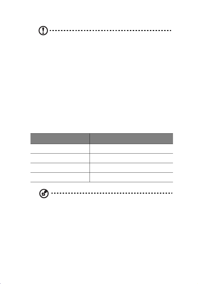
Cooling System
Cooling is provided by the two Advanced Cooling Modules (ACMs)
located at the rear of the enclosure. Each of the ACM units contain two
variable speed fans. The enclosure requires four fans for normal
operation, but will operate correctly with one fan failed (redundancy is
lost if one fan is failed in either ACM), however, it is recommended
that the failed fan be replaced as soon as possible. The ACM units can
be hot swapped. The LS Module monitors and controls the speed of
each fan. The speed is set depending on the ambient temperature and
failed status. The fans are set to full speed if one fan is failed. The
following table shows how the fan speed relates to temperature
change.
ACM Speed
Speed 1 0 to 26
Speed 2 26 to 28
Speed 3 28 to 30
Ambient Temp (oC)
Full Speed 30 +
Note: All fans in an enclosure are set to the same speed.
Page 22
Chapter 1 Introduction6
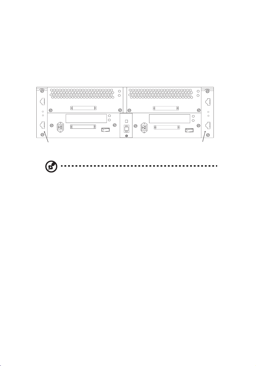
I/O Option Modules
The two rear I/O option slots (A and B) can contain a range of different
option modules. The LS module will detect the type of option module
installed.
I/O Option
Slot B
1
2
0
I
0
I
1
2
I/O Option
Slot A
Note: The above illustration shows the copper/copper I/O option
modules.
The available option modules are:
I/O Expansion Module - Copper/Copper
This 2Gb FC expansion module has two HSSDC connectors. The top
connector is the primary FC loop input port and the bottom connector
is available for FC loop expansion / input. A fibre channel loop back
terminator is not required.
I/O Expansion Module - Optical/Copper
This 2Gb FC expansion module has the SFF LC optical connector as the
FC Loop Input port. The FC loop expansion is carried out by the HSSDC
connector. A loop back terminator is not required.
Page 23

I/O Expansion Module- Optical/Optical
This 2Gb FC expansion module has two SFF LC optical connectors. The
top connector is the FC Loop Input port and the bottom connector is
for FC Loop Expansion. A loop back terminator is not required.
Altos S700 RAID Controller
The Altos S700 RAID Controller is a high performance controller,
providing two host fibre channel
interfaces. It is an intelligent, caching controller that supports
RAID levels 0, 1, 3, 5, 0+1, and JBOD. The controller enables
multiple hosts to access an array of disk drives, which can be
configured as one or more virtual storage devices (logical units).
and two device fibre channel
7
Page 24
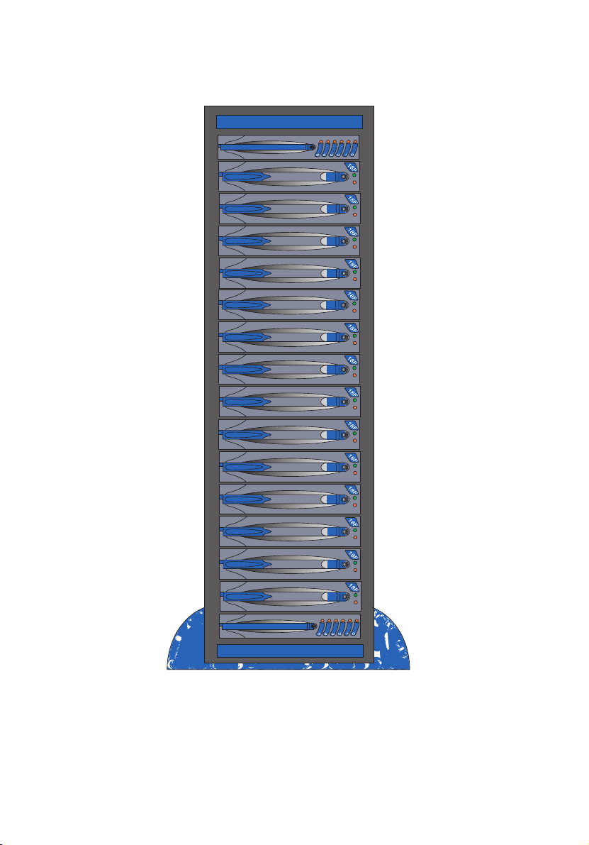
Figure 1-1: Altos S700 Series Tower Model
Chapter 1 Introduction8
Page 25
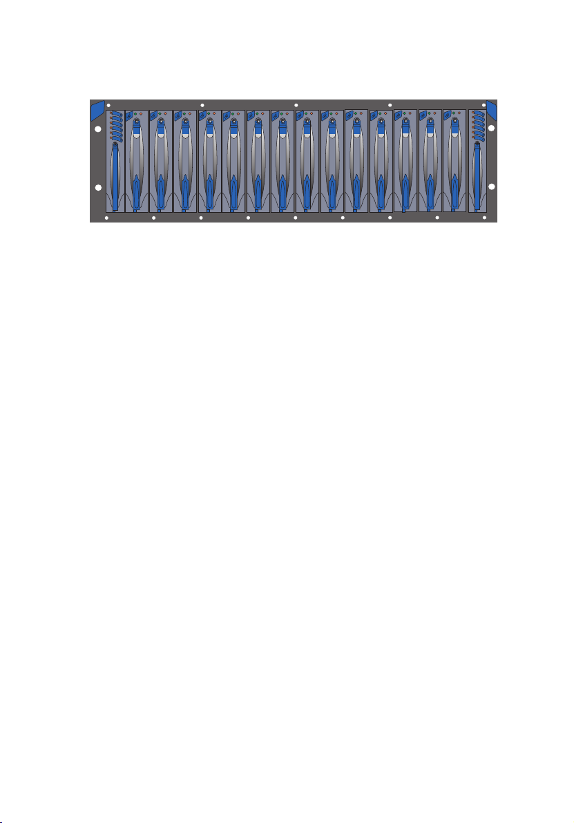
Figure 1-2: Altos S700 Series Rack Model
9
Page 26

Chapter 1 Introduction10
Page 27

Chapter 2
Installation and Setup
Page 28

This Chapter describes the installation and set up of the Altos S700 Series.
Important safety instructions are discussed along with the electrical,
mechanical and environmental precautions that need to be taken. Items
that need to be set prior to operating the Altos S700 enclosure are also
described here.
Note: Please read this Chapter carefully before attempting to install
or operate the Altos S700 Series enclosure.
Page 29
Safety Statements
The following safety statements must be read before you install or
operate the Altos S700 Series. For language translations of these
statements refer to Appendix B.
Caution: This equipment is intended only for installation in a
restricted access location.
Caution: Before attempting to install or remove any of the
components, ensure that anti-static precautions are taken. The
minimum requirement is, a properly grounded anti-static wrist
strap and ground wire.
Caution: If any of the components are removed the resulting hole
must be blocked, by installing a component blank or replacing the
component. Failure to do so can seriously restrict air flow and
cooling.
13
Caution: This device should be connected to a power source
which carries a fuse or circuit breaker that is greater than the
rating of the shelf, but also complies with national wiring
standards.
Caution: Allow disk drives and power supplies to reach room
ambient temperature before powering on the shelf.
Caution: It is recommended that, if interconnecting equipment
resides within more than one equipment rack cabinets, these
equipment racks should be at the same ground potential.
Page 30

Chapter 2 Installation and Setup14
Warning: A possible shock hazard may exist in the area of
the fan connection.
Warning: Disconnect the power cords before removing a
power supply from the enclosure.
Page 31

15
Unpacking and Initial Setup
When you receive your system, visually inspect the exterior of the
packaging for any signs of damage. If any damage is found the carrier
and Acer should be informed immediately, and they will advise you of
the appropriate action. The cartons are sealed using packaging tape
which should be cut open in the normal manner. Exercise caution when
lifting out the components. At this point the contents should be
verified against the packing list and Acer should again be notified if
any discrepancies exist. Anti-static precautions must be observed
before removing any of the components.
Page 32

Chapter 2 Installation and Setup16
Installing the System in an Equipment Rack
Before installing the Altos S700 Series in an equipment rack, it is
essential that the following guidelines are complied with, to ensure
the safe and efficient operation of the system. The Altos S700 Series
can be installed in open or closed equipment racks, with a front width
of 19”, by observing the environmental, electrical, and mechanical
precautions described below.
Ambient Temperature
Installation of the rack system in a standard 19” cabinet may lead to a
differential between the room ambient temperature and the internal
ambient temperature of the rack environment. The operating
temperature of the Altos S700 Series is between 5
it is not recommended that the system be continuously run at these
extreme temperatures. Consideration should therefore be given to
ensure that the room ambient temperature is compatible with these
specifications.
o
C to 40oC. However,
Air Flow
To ensure that the internal heat build up is properly dissipated into the
room environment, air flow should in no way be restricted. It is
essential that no air vents are blocked, and that the system is a
minimum of one meter from a solid surface such as a wall or partition.
Air flow through the Altos S700 Series is from front to rear.
Mechanical Loading
Consideration should be given to the loading of any equipment racks.
To maintain a low centre of gravity (thus reducing the likelihood of
instability) racks should be loaded (where possible) from the bottom of
the equipment rack upwards. This is recommended to ensure personal
safety.
Caution: When installing or removing a rack mount enclosure,
remove all disk drives. It is recommended that you work with at
Page 33

least one other person when installing an enclosure. This is
necessary to prevent personal injury and damage to the enclosure.
17
Page 34

Chapter 2 Installation and Setup18
Electrical Considerations
When installing the Altos S700 Series the following electrical
considerations must be applied.
Circuit Overloading
Care should be taken to ensure that the current does not exceed the
rating of the power source circuitry. This includes cabling, power
distribution units, filters and any other devices through which the main
current flows. The electrical power rating of the enclosure is 100 - 240
VAC, 10 - 5 Amps (50/60 Hz), and this must be added to the power
demands of any other electrical devices installed in the equipment rack
to arrive at a total power consumption figure. In addition, surge
currents must be catered for. Disk drives may consume twice the
amount of current at start-up time as they do during steady state
operation.
Page 35

19
Setting Fibre Channel Loop Speed (2Gb or 1Gb)
The Altos S700 Series can be operated with fibre channel loop speeds
of either 2Gb (default) or 1Gb. The loop speed is set through the use of
a jumper (JP2) located on the LS Module.
Note: If the enclosure has dual LS modules the following
procedures must be applied to both LS modules.
2Gb Operation
To set the fibre channel loop speed to 2Gb operation:
1 Remove the LS Module from the front of the enclosure.
2 On the LS Module locate the jumper position JP2 (Figure 2-1).
3 Install a jumper at JP2.
4 Replace the LS module.
1Gb Operation
To set the fibre channel loop speed to 1Gb operation:
1 Remove the LS module from the front of the enclosure.
2 On the LS Module locate the jumper position JP2 (Figure 2-1).
3 For 1Gb operation there should be no jumper installed at JP2. If
one is installed, remove it.
4 Replace the LS module.
Page 36

Chapter 2 Installation and Setup20
Figure 2-1 Location of Jumpers on LS Module
Page 37

21
Split Fibre Channel Loop Operation (Quad Loop)
Note: Quad Loop is only available on JBOD systems
The Altos S700 Series LS module allows for split FC Loop operation,
with two dual fibre channel loops of seven disk drives each. In this split
loop mode the primary port (I/O Slot A) will form a loop using the first
seven drives, 1 to 7 (from right hand side of rackmount systems). The
expansion port (I/O Slot B) will form a second loop using the remaining
7 drives, 8 to 14 (from right hand side of rackmount systems). Default
is Single Loop (no jumper).
Note: If the enclosure has dual LS modules the following
procedures must be applied to both LS modules.
Caution: Enclosures operating in split loop mode can not be daisy
chained to other enclosures.
Setting Up Split Loop Operation
To operate the Altos S700 Series enclosure in split fibre channel loop
mode, follow this procedure:
1 Remove the LS module from the front of the enclosure.
2 On the LS Module locate the jumper position JP3 (Figure 2-1).
3 To operate in split loop mode, install a jumper at JP3.
4 Replace the LS module.
Removing Split Loop Operation
To remove split fibre channel loop operation from the Altos S700 Series
enclosure, follow this procedure:
1 Remove the LS module from the enclosure and locate jumper JP3
(Figure 2-1).
2 To remove split loop operation, remove jumper JP3.
Page 38

3 Replace the LS module.
Chapter 2 Installation and Setup22
Page 39

Configuration Rules
These rules must be applied when implementing the Altos S700 Series
configurations:
• When daisy chaining, both 2Gb enclosures must be configured
identically.
• 1Gb and 2Gb systems cannot be daisy chained together.
• Two LS modules and two I/O modules are required for dual drive
loops.
• Cannot mix optical and copper I/O modules in the same enclosure
(both I/O Modules must be the same).
• Cannot mix 1Gb and 2Gb LS and I/O modules, and 1Gb and 2Gb
cables.
• 2Gb JBOD and RAID enclosures require 2Gb cables.
• 2Gb JBOD enclosures require 2Gb disk drives.
• Disk drive blanks must be ordered for any empty drive slots.
• 2Gb copper JBOD expansion configurations must be the same as
the RAID configuration.
• 2Gb optical JBOD cannot be expansion enclosure for 2Gb RAID
configuration.
• 2Gb RAID controller has two SFF LC host connectors, an HSSDC
outpur connector and a RS232 port
• 2Gb RAID requires two LSMs.
• 2Gb RAID supports autonegiotate - operates at 1Gb or 2Gb.
23
Page 40

Chapter 2 Installation and Setup24
Supported Host Bus Adapters
Contact your sales person for a list of approved Host Bus Adapters.
Page 41

25
Supported Cables
Warning: Only the following APPROVED cables must be
used with the Altos S700 Series enclosures.
This section lists the cables that must be used with the Altos S700 Series
enclosure. Failure to adhere to these guidelines may cause the
enclosure to operate incorrectly.
Copper Cables
Only the following AMPHENOL copper Fibre Channel cables must be
used with the Altos S700 Series enclosure (copper applications).
Amphenol Cable Model Numbers:
Model No. Description
CA.S7002.001 .3m 2Gb Fibre Channel, copper cable, non-equalized,
CA.S7002.002 1m 2Gb Fibre Channel, copper cable, non-equalized,
CA.S7002.003 3m 2Gb Fibre Channel, copper cable, non-equalized,
CA.S7002.004 6m 2Gb Fibre Channel, copper cable, non-equalized,
HSSDC-HSSDC
HSSDC-HSSDC
HSSDC-HSSDC
HSSDC-HSSDC
Page 42

Chapter 2 Installation and Setup26
Optical Cables
The following Fibre Channel Optical cables are available from Acer.
Please contact your sales person for more details of approved cables:
• CA.S7002.005 : 0.3m, 2Gb FC optical cable
• CA.S7002.006 : 10m, 2Gb FC optical cable
• CA.S7002.007 : 30m, 2Gb FC optical cable
• CA.S7002.008 : 150m, 2Gb FC optical cable
Page 43

Chapter 3
JBOD Configurations
Page 44

This Chapter describes the procedure for connecting your Altos S700
Series JBOD system to a host computer(s). Detailed information on
how to configure and daisy chain enclosures is also provided along
with instructions on how to set the enclosure ID.
Page 45

Setting the Enclosure ID
Each of the fourteen disk drive slots of the Altos S700 Series has a
unique identifier assigned to it. This identifier is assigned using a
combination of the slot number and the enclosure ID.
The enclosure ID is set using the enclosure ID switch, located on the
rear of the Altos S700 (see Figure 3-1).
Note: The enclosure ID must be set prior to powering on the
enclosure.
Note: Each enclosure must have a separate ID when daisy chained
together.
Note: 2Gb Amphenol cables must be used if 2Gb operation is
required.
29
Note: Contact your sales person for a list of approved HBA’s.
Page 46

Figure 3-1 Location of Enclosure ID Switch
Chapter 3 JBOD Configurations30
1
2
0
I
Enclosure ID
Switch
1
This enclosure ID switch can be set to 0 through 7.
The graphic below shows the slot number and location.
Slot location when viewed from the front of the enclosure
1
2
0
I
LSM
Slot 12
Slot 13
Slot 11
Slot 9
Slot 10
Slot 7
Slot 8
Slot 5
Slot 6
Slot 3
Slot 4
Slot 1
Slot 2
Slot 0
LSM
Page 47

The fourteen disk drive slots (0 to 13), will be assigned an identifier
based on the enclosure ID and the slot number as shown below.
Enclosure ID
Drive Slot
Slot 0 3 18 33 48 63 78 93 108
Slot 1 4 19 34 49 64 79 94 109
Slot 2 5 20 35 50 65 80 95 110
Slot 3 6 21 36 51 66 81 96 111
Slot 4 7 22 37 52 67 82 97 112
Slot 5 8 23 38 53 68 83 98 113
Slot 6 9 24 39 54 69 84 99 114
Slot 7 102540557085100115
Slot 8 112641567186101116
Slot 9 122742577287102117
0 1 2 3 4 5 6 7
31
Slot 10 13 28 43 58 73 88 103 118
Slot 11 14 29 44 59 74 89 104 119
Slot 12 15 30 45 60 75 90 105 120
Slot 13 16 31 46 61 76 91 106 121
Page 48

Chapter 3 JBOD Configurations32
Configurations
This section describes the procedures for cabling the main
configurations of the Altos S700 Series JBOD.
Note: The following configuration procedures refer to connecting
the Altos S700 Series directly to the host system. It is also possible
to connect the system using a Hub/Switch.
Caution: Before working on the enclosure, ensure that anti-static
precautions have been taken. The minimum requirement is an
anti-static wrist strap and grounding wire.
Page 49

JBOD Configurations
There are two JBOD configurations covered in this Installation Guide:
• Dual FC Loop mode (including how to daisy chain enclosures)
• Quad Loop (single enclosure with 4 FCAL loops)
Note: The following examples show the Copper/Copper I/O
Module option for illustration purposes. The configuration
procedures are identical for all I/O Module options.
Dual FC Loop Configuration
Note: For dual FC Loop enclosures there must be two LS modules
installed in the enclosure.
This section describes the procedure for connecting a dual FC Loop
configuration to your host computer, and how to daisy chain these
enclosures together.
To connect the dual FC Loop enclosure to the host:
33
Note: You will need two HBA’s in your host system, or a single
HBA with support for two connections. A hub, switch or two hosts
with HBA may also be used.
1 Insert the connector on the first cable, into the top connector on
the first I/O module (see Figure 3-2).
2 Insert the other end of this cable into the connector on your HBA.
3 Insert the connector on the second cable, into the top connector
on the second I/O module (see Figure 3-2).
4 Insert the other end of this cable into the connector on your HBA.
Note: For details on your host and/or HBA refer to the
documentation that was supplied with the host / HBA.
Page 50

Chapter 3 JBOD Configurations34
T
Figure 3-2 Connecting dual FC Loop configuration to a host
o HBA
1
2
0
I
To HBA
1
2
0
I
See Appendix C for Loop Diagram.
To daisy chain enclosures together, connect link cables from the
bottom connectors on the I/O modules of the first enclosure to the top
connectors of the I/O modules on the next enclosure (see Figure 3-3).
Note: A maximum of eight enclosures may be daisy chained
together.
Page 51

Figure 3-3 Daisy chaining dual FC Loop enclosures
e
t
re
35
To HBA
To next
nclosure
To HBA
1
2
0
I
1
2
0
I
1
2
0
I
1
2
0
I
To nex
enclosu
See Appendix C for Loop Diagram.
Caution: When daisy chaining enclosures, you must ensure that
each enclosure has a unique Enclosure ID.
Quad Loop Configuration
Note: Quad loop configuration requires that the enclosure be
configured in split loop mode. To set split loop mode, a jumper
must be installed at jumper location JP3 on each LS module in the
enclosure.
Page 52

Chapter 3 JBOD Configurations36
4
D
This section describes the procedure for connecting the enclosure in
quad loop mode. For this configuration there must be two LS modules
and two I/O modules installed in the enclosure.
1 Remove both LS modules from the enclosure and install a jumper,
at jumper location JP3 if one is not already installed. This sets the
enclosure to operate in split loop mode.
2 Attach cables to the top and bottom connector of both I/O
modules (see Figure 3-4).
3 Attach the other end of these four cables to your host systems.
Figure 3-4 Cabling the Quad Loop Configuration
rives 1-7
Drives 1-7
1
2
Loop B
0
I
Drives 8-14
Drive 10
Drive 11
Drive 12
Drive 13
Drive 14
LSM
Drive 6
Drive 8
Drive 5
Drive 7
Drive 9
Drive 1
Drive 2
Drive 3
Drive 4
LSM
1
2
Loop A
0
I
Drives 8-1
Page 53

Connecting a Power Source
The Altos S700 enclosure supports dual AC power supplies. Only one
power supply is required for normal operation. However, a second,
optional power supply may be added to provide a redundant power
system. Each power supply has its own AC power inlet.
37
Caution: Power supply cords shall have conductors with a cross-
2
sectional area not less than 4mm
. This cross-sectional area
corresponds to a minimum 10AWG wire.
Connecting an AC Power Source
1 Ensure all cables have been attached as described in the preceding
sections.
2 Attach the AC power cords to the power supplies and turn the
power supply switches to the On (-) position (see Figure 3-5).
Figure 3-5 Attaching the AC power cords
1
2
0
I
Insert Power cords into
power connectors
Warning: This equipment must be connected to an earthed
mains socket outlet. Ensure the power cabling provides
earthing continuity to the equipment.
1
2
0
I
Page 54

Chapter 3 JBOD Configurations38
Disk Drive Spin Up Sequence
At power on, the LS module will perform its internal start up
initialization routine. Then the LS module will assert the disk drive
START_1 and START_2 motor start signals low for disk drive slots 7
through 13, which will spin up the first 7 disk drives immediately. The
LS module will then assert the disk drive START_2 motor start signal
low and leave the START_1 motor start signal high for disk drive slots 0
through 6 which will command the second seven disk drives to spin up
after a delay of 12 seconds times the modulo 8 value of the numeric
SEL_ID of the disk drive.
Once the enclosure is powered up and all 14 drives are spun up as
depicted above, the enclosure will support immediate drive spin up
with two power supplies present.
Modulo 8
The drive spin up sequence above uses modulo 8 to calculate the spin
up delay. Modulo 8 is determined by:
(SHELF ID x DRIVE NUMBER)/8 = NUMBER + REMAINDER
It is the REMAINDER value that is used for the calculation as it is
always between 0 and 7 (hence modulo 8). The drive spin up time can
then be calculated as follows:
REMAINDER x MODE PAGE SETTING = SPIN UP DELAY (Seconds)
EXAMPLE:
Spin Up Delay would be 7 x 12, or 84 seconds.
A typical Mode Page Setting is 12, so if the Remainder = 7, the
Page 55

Chapter 4
RAID Configurations
Page 56

This chapter describes how to set up, configure and use the
Altos S700 Series RAID Controller. Some general information
about the RAID controller is also provided.
Page 57

41
Altos S700 Series RAID Controller Introduction
The Altos S700 RAID Controller is a high performance controller,
providing two host fibre channel
interfaces. It is an intelligent, caching controller that supports
RAID levels 0, 1, 3, 5, 0+1, and JBOD. The controller enables
multiple hosts to access an array of disk drives, which can be
configured as one or more virtual storage devices (logical units).
The controller provides continuous access to data in the event of a disk
drive failure. When configured in a dual-active controller system, the
RAID controller also provides continuous access to data in the event of
a controller failure. This dual-active controller system is one in which
two controllers share
access to the same array of disk drives. In the
event of a controller failure, controller operations are assumed
by the surviving controller through a failover process. The failed
controller can then be removed and replaced while the system
is online. The new controller resumes processing array
operations in a failback process. During failover and failback,
write cache coherency is maintained with the disk drives.
Three circuit boards make up the RAID Controller:
• Controller: The controller circuit board contains the main
controller and peripheral functions, including processor, controlstore memory, XOR engine and cache controller, and host and
device fibre channel input/output processors (IOPs).
• I/O: The I/O circuit board provides the interface to the disk drive
enclosure (device) and host as well as general support functions. It
also contains the switching power supply, which generates +3.3
Vdc and +2.5 Vdc from +5 Vdc, hot-swap circuits, and battery
backup unit (BBU) circuits.
1
• Ethernet
interface to the controller, and connections for debug and out-ofband service to the host and device PCI busses.
: The ethernet circuit board provides an ethernet
and two device fibre channel
The RAID Controller requires a minimum of two circuit boards: the
controller and I/O. The controller and I/O
circuit boards are
connected using two 38-pin controlled impedance connectors.
1
This option is not yet available. Please contact your sales person for availability information.
Page 58

Chapter 4 RAID Configurations42
The controller, I/O, and ethernet circuit boards are assembled
into a stack with the controller and ethernet boards mounted
to a controller cover plate and the I/O board mounted to the
controller board. When the ethernet circuit board is used, it is
mounted to the controller circuit board. Figure 4-1 shows the
three circuit boards in their relative positions.
Figure 4-1 RAID Controller Circuit Boards
Features of the RAID Controller include:
• Main processor coupled with a companion chip
• Proprietary XOR engine ASIC that provides data processing XOR
function and data cache SDRAM control
• Four 2Gb-capable fibre protocol chips for the device and host ports
• Dual internal 528 MB/s, 64-bit, 66 MHz PCI buses
• Separate memory areas for processor and user data
• Scalable data cache memory: 128, 256, 512 MB DIMMs
• 128 KB NVRAM configuration memory
• Real Time Clock
• 4 MB Flash PROM
• Transparent failover/failback with multiple target ID support
The I/O circuit board includes a Battery Backup Unit (BBU) that
maintains memory content in case of AC power failure. Power for the
BBU is provided by a battery pack mounted in the fan module of the
enclosure.
Page 59

43
RAID Controller Circuit Boards
This section gives a brief description of the RAID controller circuit
boards that are inside the RAID controller module.
Caution: The description of the RAID controller circuit boards
provided below is for information only. Only qualified service
personnel should open the RAID Controller module.
Controller Circuit Board
The controller circuit board oversees and regulates the flow of data
from a host through the I/O circuit board to the disk arrays in the Altos
S700 enclosure. The controller circuit board performs these operations
with a proprietary architecture, using the following components:
• Main microprocessor and companion chip
• Control-store memory
• Memory Controller/Hardware XOR Engine ASIC (XOR ASIC)
• Flash PROM
• Non-volatile RAM (NVRAM)
• Dual universal asynchronous receiver/transmitter (DUART)
• Fibre Channel I/O processors
• Cache DIMM memory
I/O Circuit Board
The I/O circuit board provides the interface between the enclosure and
a host, as well as general support functions. The I/O circuit board
provides the following:
• Connections to the host
• Connections to the enclosure
• Dual switching power supply for +3.3 V and +2.5 V
• Hot pluggability for the controller
• Support for the BBU
Page 60

Chapter 4 RAID Configurations44
The I/O circuit board has two SFF optical transceivers supporting
shortwave multimode fibre on the host side and a 90-pin controlled
impedance (50 Ohm) connector on the device side. An HSSDC
connector with repeaters on the expansion loop provides for a copper
connection between one of the device channels and an expansion
module. Port bypass circuitry on the I/O circuit board enables quadplex
operation on a second host loop. The I/O board has seven LEDs to
indicate subsystem status.
RS232 Serial Port
The 3-pin, RS232 Serial Port is located on the RAID controller and
provides VT100 terminal emulation capabilities. It can be used to
configure and manage the storage array. This RS232 port applicable
when attaching to operating systems that are not supported by Acer’s
management software, or for using a CLI to create scripts.
Page 61

RAID Controller Location
er
R
or
The RAID controller is installed in the rear of the enclosure in the
location shown in Figure 4-2.
Figure 4-2 RAID Controller location
AID Controller
1
2
RAID Controll
1
2
45
1
2
3
4
5
6
7
0
I
1
2
3
4
5
6
7
0
I
The above illustration shows a dual RAID configuration.
The main parts of the RAID Controller are described in Figure 4-3.
Figure 4-3 Main components of RAID controller
HSSDC Connect
RS232
FC Host Connectors (SSF optical)
1
2
3
Status LEDs
4
5
6
7
Page 62

Chapter 4 RAID Configurations46
RAID Controller Status LEDs
The RAID controller has 7 Status LEDs as shown above. describes what
these LEDs signify.
Controller Status LEDs
LED Description
1 Yellow - Not Ready. Normally Off. Goes On during power up
2 Green - Ready. Normally On
3 Green - Dirty Cache. On when there is data in cache.
4 Yellow - BBU Fault. Normally Off.
5 Green - Partner Fail. Normally Off
6 Green - Device Activity i.e. on drive channels. Flashes with
7 Green - Host Activity. Flashes with activity.
sequence.
activity.
Page 63

47
RAID Controller Configurations
This section describes how to cable the two standard RAID controller
configurations: Single RAID Controller and Dual RAID Controller (dual
active). The procedure for daisy chaining these standard configurations
to expansions enclosures is also described. This section also describes
how to set the enclosure ID.
Page 64

Chapter 4 RAID Configurations48
Setting the Enclosure ID
Each of the fourteen disk drive slots of the Altos S700Altos S700 Series
has a unique identifier assigned to it. This identifier is assigned using a
combination of the Slot number and the enclosure ID.
The enclosure ID is set, using the enclosure ID switch, located on the
rear of the Altos S700 (see Figure 4-4).
Note: The enclosure ID must be set prior to powering on the
enclosure.
Note: Each enclosure must have a separate ID when daisy chained
together.
Figure 4-4 Location of Enclosure ID Switch
1
2
1
2
3
4
5
6
7
0
I
Enclosure ID
Switch
1
This enclosure ID switch can be set to 0 through 7.
1
2
1
2
3
4
5
6
7
0
I
Page 65

The graphic below shows the slot number and location.
o
Slot location when viewed from the front of the encl
LSM
Slot 13
Slot 1
Slot 2
Slot 0
LSM
Slot 3
Slot 4
Slot 5
Slot 6
Slot 7
Slot 8
Slot 9
Slot 10
Slot 11
Slot 12
The fourteen disk drive slots (0 to 13), will be assigned an identifier
based on the enclosure ID and the slot number as shown in .
Disk Drive Identifier Table
49
Enclosure ID
Drive Slot
Slot 0 3 18 33 48 63 78 93 108
Slot 1 4 19 34 49 64 79 94 109
Slot 2 5 20 35 50 65 80 95 110
Slot 3 6 21 36 51 66 81 96 111
Slot 4 7 22 37 52 67 82 97 112
Slot 5 8 23 38 53 68 83 98 113
Slot 6 9 24 39 54 69 84 99 114
Slot 7 102540557085100115
Slot 8 112641567186101116
Slot 9 122742577287102117
Slot 10 13 28 43 58 73 88 103 118
Slot 11 14 29 44 59 74 89 104 119
Slot 12 15 30 45 60 75 90 105 120
0 1 2 3 4 5 6
7
Page 66

Chapter 4 RAID Configurations50
Enclosure ID
Drive Slot
Slot 13 16 31 46 61 76 91 106 121
0 1 2 3 4 5 6
7
Page 67

51
Configurations
This section shows how to connect the RAID enclosures to a host
system(s). The procedure for daisy chaining the enclosures together is
also described.
Single RAID Controller Configuration
In this configuration only one RAID controller is installed in the
enclosure’s I/O slot. The second I/O slot must contain an I/O module or a
blank plate.
Caution: For all RAID configurations, there must be two LS
modules installed in the enclosure.
Note: The following configuration procedures refer to connecting
the Altos S700 Series directly to the host system. It is also possible
to connect the system using a Hub/Switch.
Caution: Before working on the enclosure, ensure that anti-static
precautions have been taken. The minimum requirement is an
anti-static wrist strap and grounding wire.
To connect this configuration to a host system, follow this procedure:
Connecting a Single RAID Controller to a Host
1 Plug both host cables into the host connectors on the RAID
controller (see Figure 4-5).
Note: For single HBA configurations only one host connector will
need to be used.
2 Connect the opposite ends of these host cables, to the HBA’s of the
host system.
Note: For details on your host and/or HBA refer to the
documentation that was supplied with the host / HBA.
Page 68

Chapter 4 RAID Configurations52
Figure 4-5 Single RAID Controller to Host Connector
1
2
0
I
1
2
HBA 1
1
2
HBA 2
3
4
5
6
0
I
7
Daisy Chaining a Single Controller Enclosure
To daisy chain the RAID enclosure to an expansion enclosure, connect
link cables from the RAID controller to the top connectors of the I/O
modules of the expansion enclosure (see Figure 4-6).
Note: A maximum of eight enclosures may be daisy chained
together.
Page 69

Figure 4-6 Daisy Chaining Single Controller Enclosure
L
53
ink Cable
I/O Module
1
2
0
I
Connect this
To next
enclosure
cable for dual
loop operation
1
2
0
I
Total of 8 enclosures may be daisy chained together.
Link Cable
Caution: When daisy chaining enclosures, you must ensure that
each enclosure has a unique Enclosure ID.
RAID Controller
1
2
0
I
1
2
0
I
To next
enclosure
HBA 1
1
2
HBA 2
3
4
5
6
7
Page 70

Chapter 4 RAID Configurations54
Dual RAID Controller Configuration
In this configuration two RAID Controllers are installed in the
enclosures I/O slots.
Note: The following configuration procedures refer to connecting
the Altos S700 Series directly to the host system. It is also possible
to connect the system using a Hub/Switch.
Caution: Before working on the enclosure, ensure that anti-static
precautions have been taken. The minimum requirement is an
anti-static wrist strap and grounding wire.
To connect this configuration to a host system, follow this procedure:
Connecting Dual RAID Controllers to a Host System
Note: This example configuration assumes that the RAID
enclosure is being attached to two separate host systems, each
containing two HBA’s. Other configurations, such as one host with
4 HBA’s are also possible.
1 Plug two host cables in to the host connectors of the first RAID
controller (one cable into each FC connector).
2 Plug the opposite ends of these cables into the HBA’s of the first
host system (see Figure 4-7)
3 Plug two host cables in to the host connectors of the second RAID
controller (one cable into each FC connector).
4 Plug the opposite ends of these cables into the HBA’s of the second
host system (see Figure 4-7)
Page 71

Figure 4-7 Dual RAID Controller Configuration
55
Host B
HBA 1
HBA 2
1
2
1
2
3
4
5
6
7
0
I
1
2
Host A
HBA 1
1
2
HBA 2
3
4
5
6
7
0
I
Daisy Chaining a Dual Controller Enclosure
To daisy chain the RAID enclosure to an expansion enclosure, connect
link cables from the RAID enclosure to the top connectors of the I/O
modules of the expansion enclosure (see Figure 4-8).
Note: A maximum of eight enclosures may be daisy chained
together.
Page 72

Chapter 4 RAID Configurations56
Figure 4-8 Daisy Chaining a Dual Controller Enclosure
Host B
HBA 1
HBA 2
1
2
1
2
3
4
5
To next
enclosure
6
7
Link Cable
Total of 8 enclosures may be daisy chained together.
0
I
Link Cable
1
2
0
I
Caution: When daisy chaining enclosures, you must ensure that
each enclosure has a unique Enclosure ID.
I
I
1
2
0
1
2
0
enclosure
To next
Host A
HBA 1
1
2
HBA 2
3
4
5
6
7
Page 73

Connecting a Power Source
The Altos S700 enclosure supports dual AC power supplies. Only one
power supply is required for normal operation. However, a second,
optional, power supply may be added to provide a redundant power
system. Each power supply has its own AC power inlet.
57
Caution: Power supply cords shall have conductors with a cross-
2
sectional area not less than 4mm
. This cross-sectional area
corresponds to a minimum 10AWG wire.
Connecting an AC Power Source
1 Ensure all cables have been attached as described in the preceding
sections.
2 Attach the AC power cords to the power supplies and turn the
power supply switches to the On (-) position (see Figure 4-9).
Figure 4-9 Attaching the AC power cords
1
2
1
2
3
4
5
6
7
0
I
Insert Power cords into
power connectors
Warning: This equipment must be connected to an earthed
mains socket outlet. Ensure the power cabling provides
earthing continuity to the equipment.
1
2
1
2
3
4
5
6
0
I
7
Page 74

Chapter 4 RAID Configurations58
Disk Drive Spin Up Sequence
At power on, the LS module will perform its internal start up
initialization routine. Then the LS module will assert the disk drive
START_1 and START_2 motor start signals low for disk drive slots 7
through 13, which will spin up the first 7 disk drives immediately. The
LS module will then assert the disk drive START_2 motor start signal
low and leave the START_1 motor start signal high for disk drive slots 0
through 6 which will command the second seven disk drives to spin up
after a delay of 12 seconds times the modulo 8 value of the numeric
SEL_ID of the disk drive.
Once the enclosure is powered up and all 14 drives are spun up as
depicted above, the enclosure will support immediate drive spin up
with two power supplies present.
Modulo 8
The drive spin up sequence above uses modulo 8 to calculate the spin
up delay. Modulo 8 is determined by:
(SHELF ID x DRIVE NUMBER)/8 = NUMBER + REMAINDER
It is the REMAINDER value that is used for the calculation as it is
always between 0 and 7 (hence modulo 8). The drive spin up time can
then be calculated as follows:
REMAINDER x MODE PAGE SETTING = SPIN UP DELAY (Seconds)
EXAMPLE:
Spin Up Delay would be 7 x 12, or 84 seconds.
A typical Mode Page Setting is 12, so if the Remainder = 7, the
Page 75

Chapter 5
System Monitoring
Page 76

This Chapter describes the devices used to monitor the Altos
S700 Series. The location of the monitoring LEDs and how to
interpret them is described.
Page 77

61
Overview
The front mounted LS module is the main monitoring device of the
Altos S700 Series. This module is complemented by status and fault
LEDs, mounted on all the major components of the enclosure, such as,
disk drives, power supplies, Advanced Cooling Modules (ACMs), and
RAID Controller. All these monitoring devices are discussed in the
following sections.
Page 78

Chapter 5 System Monitoring62
LS Module
The LS Module (Loop Resiliency and SES Module) provides monitoring
and control for the Altos S700 Series. The module reports status and
receives control information over the Enclosure Services Interface (ESI)
port of any of the fourteen disk drives installed in the enclosure. The LS
Module also provides loop resiliency for the Fibre Channel loop (in the
form of Port Bypass Circuits).
1
The Altos S700 Series contains one LS Module
second optional LS Module is available to provide active/passive failover for the enclosure services communication, and to provide a
second Fibre Channel Loop. Only one LS Module communicates (using
ESI communication) with the host system at any one time, but both LS
modules will continuously monitor the system. If the active LS Module
fails, then the ESI communication with the host system will be taken
over by the passive LS Module.
LS Module Features
• Monitoring/Control for 2 Power Supplies and 2 ACMs
• Reports status and receives control information via the FC loop
• Microcontroller for data processing, control and communications
• Volatile and non-volatile memory for the microcontroller
• Temperature sensor
• Audible alarm with manual and software disable
• FC link monitoring and status information
• Firmware download capability
• Reporting of PSU, LS module, I/O module, and backplane serial
number and revision
• I/O module and backplane type reporting
• Control of 6 front LEDs for enclosure and module status
• I/O option slot status monitoring
1
For RAID configurations, there must be two LS modules installed.
as standard. However, a
Page 79

63
L
L
L
L
L
L
Altos S700 Enclosure LEDs
The Altos S700 Series has six LEDs located on each of the front
mounted LS Modules. These LEDs show the status of the enclosure
power, Fibre Channel Loops, LS Module status and the operating mode
of the enclosure (1GB or 2Gb operation). Figure 5-1 shows the location
of the LEDs
Figure 5-1 Location of Altos S700 Enclosure LEDs
ED 0
ED 1
ED 2
ED 3
ED 4
ED 5
0
1
2
3
4
5
Page 80

Chapter 5 System Monitoring64
The table below shows the meaning of each of the LEDs, and how to
interpret them.
Description Color Indication
LED 0 Power On Green Normally ON, indicates power is applied.
LED 1 Shelf Fault Amber Normally OFF indicates no faults exist in
LED 2 FC Loop A Green ON indicates FC Loop A closed. OFF
LED 3 FC Loop B Green ON indicates FC Loop B closed. OFF
LED 4 LS Fault Amber Normally OFF indicating that the LS
LED 5 2Gb Operation Green ON indicates the FC loop is operating at
OFF indicates no power.
the enclosure. ON indicates a fault.
Flashing of this LED indicates the both a
1GB and a 2Gb I/O module has been
detected.
indicates FC Loop A open
indicates FC Loop B open.
Module has no fault. ON indicates an LS
Module fault. Flashing of this LED
indicates that the LS is a 1GB LS module in
a 2Gb system.
2Gb/Sec speed. OFF indicates the FC Loop
is operating at 1GB/Sec Speed. Flashing
of this LED indicates that the LS module is
set to an incorrect speed.
Note: If enabled, the audible alarm will sound when an error is
detected.
Caution: If 1GB and 2Gb hardware is mixed in an enclosure at
power up, and the enclosure is set to 2Gb, the drives will not spin
up and LEDs 1 and 5 will be flashing.
Page 81

65
Disk Drive LEDs
Each disk drive carrier has two LED indicators visible from the front of
the Altos S700 enclosure. The green disk drive ready LED is controlled
by the disk drive, and the bi-colour LED is controlled by the LS Module.
The following table shows how to interpret these LEDs.
Drive Ready
Green LED
Drive Controlled Off Off Slot empty, ready for insert
Drive Controlled On Off Drive online, ready for
Drive Controlled ON 125ms
Drive Controlled ON 250ms
Drive Controlled On 500ms
Drive Controlled Off On 125ms
Drive Controlled Off
a.
The shelf fault Amber LED is On. This is visible from the front of the enclosure
Bicolor LED
Green
Off 125ms
Off 250ms
Off 125ms
Off
Bicolor LED
Amber
Off
Off
Off
Off
Off
Off
Off 125ms
On 125ms
Off 750ms
Condition
operation
Drive Identify (POD)
Prepare for removal
Drive Rebuild
Drive Fail
Drive off-line, Loop A or
a
Loop B
Note: If enabled, the audible alarm will sound when an error is
detected.
Page 82

Figure 5-2 Disk Drive Carrier LEDs
Chapter 5 System Monitoring66
Disk Drive Ready
(Green)
BiColor LED
(Green/Amber)
18F
Page 83

67
Power Supply LEDs
The Altos S700 Series uses two AC power supplies. The AC power
supplies provide 853W peak output power and 673W continuous
output power.
The Altos S700 Series power supply has two LED indicators on it, which
are visible from the rear of the enclosure. The green Power OK LED is
on when the power supply is operating normally. This green LED is
driven by the power supply, and indicates that the power supply
output voltages are operating normally. The power supply amber Fault
LED is driven by the LS Module and power supply. This amber LED is ON
when the LS Module detects a power supply fault, or it will flash, when
the power supply Locate feature is selected.
Note: If enabled, the audible alarm will sound when an error is
detected
Figure 5-3 Power Supply LEDs
Fault LED
Power OK
0
I
Page 84

Chapter 5 System Monitoring68
Advanced Cooling Module (ACM) LEDs
The Altos S700 Series has two variable speed fans per advanced cooling
module. Each of the two ACMs on the rear of the Altos S700 Series
enclosure has two fault LEDs visible from the rear of the enclosure. The
LEDs are labeled “1” and “2” to correspond with the two fans inside
the ACM assembly. These LEDs are normally off and will only be on
when a fault is detected in a fan by the LS Module.
Note: The audible alarm will sound when an error is detected.
Figure 5-4 Advanced Cooling Module LEDs
Fan2
Fan1
1
2
Fan1 Fault
Fan2 Fault
Page 85

RAID Controller LEDs
or
The RAID controller has 7 LEDs located and numbered as shown.
Figure 5-5 RAID controller LEDs
HSSDC Connect
69
RS232
FC Host Connectors (SSF optical)
1
2
3
4
5
6
7
Status LEDs
The table below describes the LEDs meaning.
Controller Status LEDs
LED Description
1 Yellow - Not Ready. Normally Off. Goes On during power up
sequence.
2 Green - Ready. Normally On
3 Green - Dirty Cache. On when there is data in cache.
4 Yellow - BBU Fault. Normally Off.
5 Green - Partner Fail. Normally Off
6 Green - Device Activity i.e. on drive channels. Flashes with
activity.
7 Green - Host Activity. Flashes with activity.
Page 86

Chapter 5 System Monitoring70
Page 87

Chapter 6
Installing and
Removing Components
Page 88

This Chapter describes the procedures for installing and removing
the replaceable components in the Altos S700 Series.
Warning: The module handles are to facilitate the easy
insertion and removal of the modules, they should not
be used to lift and/or carry the enclosure.
Page 89

Location of the Components
r
Disk Drives
Module
ACMs
73
LS
Module
I/O Module/
RAID Controller
1
2
0
I
Power Supplies
1
2
0
I
I/O Module/
RAID Controlle
Page 90

Chapter 6 Installing and Removing Components74
Installing and Removing a Disk Drive Carrier
The disk drive carriers are located in the front of the enclosure. Follow
these procedures to install and remove the disk drive carrier.
Installing a Disk Drive Carrier
1 Select the disk drive slot into which the disk drive carrier is to be
installed and remove the carrier blank if there is one installed.
2 Orient the disk drive carrier such that the LEDs are on the top (on
the right for desk side systems).
3 With the cam lever fully open slide the carrier into the slot until
the lever starts to close.
4 Fully close the cam lever. The lever is fully closed, and the drive
locked in place, when the lever “clicks” into position.
Removing a Disk Drive Carrier
1 Using your finger, release the locking tab by pressing it in the
direction shown in Figure 5-1, and pull the cam lever towards you.
2 Fully open the cam lever. (approx. 90
3 With the cam lever open wait for at least one minute to allow the
disk drive to spin down fully before removing it.
4 Gently, pull the disk drive carrier out of the enclosure.
o
to enclosure).
Caution: Immediately replace the disk drive carrier or install a
disk drive carrier blank to maintain correct airflow.
Page 91

Figure 6-1 Disk Drive Carrier
Push locking tab in this direction to open
18F
75
Cam Lever
Page 92

Chapter 6 Installing and Removing Components76
Installing and Removing an LS Module
The LS Modules are located in the front of the enclosure. Follow these
procedures to install and remove the LS Modules.
Installing an LS Module
1 Select the LS Module slot in to which the LS Module is to be
inserted and remove the LS blank if one is installed.
2 Orient the LS Module such that the LEDs are on the top (on the
right for deskside systems).
3 With the cam lever fully open slide the LS Module into the slot
until the lever starts to close.
4 Fully close the cam lever. The lever is fully closed, and the LS
Module locked in place, when the lever “clicks” into position.
Removing an LS Module
1 Using your finger, release the locking tab by pressing it in the
direction shown in Figure 5-2, and pull the cam lever towards you.
2 Fully open the cam lever (approx. 90
3 Gently, pull the LS Module out of the enclosure.
o
to enclosure).
Caution: Immediately replace the LS Module to maintain correct
airflow.
Page 93

Figure 6-2 LS Module
Push locking tab in this direction to open
77
0
1
2
3
4
5
Cam Lever
Page 94

Chapter 6 Installing and Removing Components78
Installing and Removing a Power Supply
The power supplies are located in the rear of the enclosure. Follow
these procedures to install and remove the power supplies.
Installing a Power Supply
1 Select the power supply slot into which the power supply is to be
inserted and remove the carrier blank if there is one installed.
2 Orient the power supply, such that the LEDs are on the top (on the
right hand side for rack mount systems).
3 Gently slide the power supply into the empty power supply slot.
4 Secure in place using the two fixing screws (torque setting 0.3Nm).
5 Install the power cable.
Removing a Power Supply
1 Turn off the power supply, and remove the power cable.
2 Loosen the two fixing screws.
3 Using the power supply handle, gently slide it out of the enclosure.
Caution: Immediately replace the power supply carrier or install a
power supply carrier blank to maintain correct airflow.
Figure 6-3 Power Supply
Inlet
AC
Handle
0
I
Switch
On/Off
Page 95

79
Installing and Removing an Advanced Cooling Module
The advanced cooling modules are located in the rear of the enclosure.
Follow these procedures to install and remove the advanced cooling
modules.
Installing an Advanced Cooling Module
1 Select the advanced cooling module slot into which the module is
to be installed.
2 Orient the module, such that the LEDs are on the top (on the right
hand side for rack mount systems).
3 Gently slide the ACM into the empty ACM slot.
4 Secure in place using the two fixing screws (torque setting 0.3Nm).
Removing an Advanced Cooling Module
1 Loosen the two fixing screws.
2 Using the advanced cooling module handle, gently slide it out of
the enclosure.
Caution: Immediately replace the ACM to maintain correct
airflow.
Figure 6-4 Advanced Cooling Module
Handle
LEDs
1
2
Page 96

Chapter 6 Installing and Removing Components80
Installing and Removing an I/O Module/RAID Controller
Note: In the following section, “I/O Module” is taken to include
the RAID Controller in addition to the I/O Module.
The I/O module is located in the rear of the enclosure. Follow these
procedures to install and remove the I/O module.
Installing an I/O Module/RAID Controller
1 Remove the I/O module blank if there is one installed.
2 Gently insert the I/O module into the slot.
3 Secure in place using the two fixing screws (torque setting 0.3Nm).
4 Connect the cables as described in Chapter 3.
Removing an I/O Module/RAID Controller
1 Remove all cables.
2 Loosen the two fixing screws.
3 Using the module handle, gently slide the I/O Module out of the
slot.
Caution: Immediately replace the carrier or install an I/O module
blank to maintain correct airflow.
Page 97

Appendix A
Safety Statement
Translations
Page 98

Caution:
This equipment is intended only for installation in a restricted
access location.
Caution: Dieses Gerät sollte nur an einem Ort mit
Zugangskontrolle installiert werden.
Denna utrustning får endast installeras på ställe med begränsad
åtkomst.
Laitteisto on tarkoitettu asennettavaksi ainoastaan sivullisilta
suojattuun paikkaan.
Dette udstyr er kun beregnet til installation i et område med
begrænset adgang.
Appendix A Safety Statement Translations82
Dette utstyret er bare beregnet for installering på steder med
adgangsbegrensning.
Allow disk drives and power supplies to reach room ambient
temperature before powering on the shelf.
Ehe Laufwerke und Netzteile an die Stromversorgung
angeschlossen werden, sollten sie sich an die Raumtemperatur
angepasst haben.
Page 99

Låt skivdrivenheter och strömtillförsel nå rumstemperatur innan
strömförsörjningen slås på.
Ennen kuin kytket virran hyllyyn sijoitettuihin levyasemiin ja
teholähteisiin, odota, että laitteet saavuttavat huoneiston
lämpötilan.
Sørg for, at drev og strømforsyninger har opnået
rumtemperaturer, før strømmen tilsluttes hylden.
La diskstasjoner og strømforsyninger nå romtemperatur før du
slår på strømmen til hyllen.
It is recommended that if interconnecting equipment resides
within more than one equipment rack cabinet, these rack cabinets
should be at the same ground potential.
83
: Befinden sich Verbindungselemente in mehr als einem RackGehäuse, sollten die Racks dasselbe Massepotential aufweisen.
Vi rekommenderar, om förbindelseutrustning finns i mer än ett
utrustningshyllskåp, att dessa hyllskåp ligger på samma
jordpotential.
Jos toisiinsa yhdistettyjä laitteita sijaitsee useammassa kuin
yhdessä kehyksessä, on suositeltavaa sijoittaa kyseiset kehykset
samalle tasolle.
Page 100

Appendix A Safety Statement Translations84
Hvis der i mere end ét udstyrsrackkabinet er indbyrdes forbundet
udstyr, bør disse kabinetter have samme grundspænding.
Dersom sammenkoblingsutstyr er montert i mer enn ett kabinett i
utstyrsrack, anbefales det at kabinettene blir montert slik at de
har samme jordingspotensial.
Before attempting to install or remove any of the components,
ensure that anti-static precautions have been taken. The minimum
requirement is a properly grounded anti-static wrist strap and
grounding wire.
Vor dem Entfernen oder Installieren einer Komponente sollte
sichergestellt werden, dass antistatische Vorsichtsmaßnahmen
ergriffen wurden. Mindestanforderung sind ein ordnungsgemäß
geerdetes Antistatik-Armband und ein Erdungskabel.
Se till att antistatiska åtgärder vidtages innan någon av
komponenterna installeras eller avlägsnas. Minimikravet är ett
ordentligt jordat antistatiskt armband och jordledning.
Ennen komponenttien asentamista tai poistamista varmista, että
antistaattisista varotoimenpiteistä on huolehdittu.
Vähimmäisvaatimuksina on asianmukaisesti maadoitettu
antistaattinen rannehihna ja maadoitusjohto.
Før du forsøger at installere eller fjerne en af komponenterne,
skal du tage antistatiske forholdsregler. Minimumskravet er en
korrekt jordet, antistatisk håndledsrem og en afleder.
 Loading...