

Page 1

Acer Altos R920 Series
User’s Guide
Page 2

Copyright © 2007 Acer Incorporated
All Rights Reserved.
Acer Altos R920 Series
User’s Guide
Changes may be made periodically to the information in this publication without obligation
to notify any person of such revision or changes. Such changes will be incorporated in new
editions of this manual or supplementary documents and publications. This company makes
no representations or warranties, either expressed or implied, with respect to the contents
hereof and specifically disclaims the implied warranties of merchantability or fitness for a
particular purpose.
Record the model number, serial number, purchase date, and place of purchase information in
the space provided below. The serial number and model number are recorded on the label
affixed to your server. All correspondence concerning your unit should include the serial
number, model number, and purchase information.
No part of this publication may be reproduced, stored in a retrieval system, or transmitted, in
any form or by any means, electronic, mechanical, photocopy, recording, or otherwise,
without the prior written permission of Acer Incorporated.
Acer Altos R920 Series
Model Name : R920
Part Number: MU.R2900.001
Purchase Date:
Place of Purchase:
Acer and the Acer logo are registered trademarks of Acer Inc. Other company’s product names
or trademarks are used herein for identification purposes only and belong to their respective
companies.
Page 3

iii
Notices
FCC declaration of conformity
This device complies with Part 15 of the FCC Rules. Operation is subject to the
following two conditions: (1) this device may not cause harmful interference,
and (2) this device must accept any interference received, including interference
that may cause undesired operation.
The following local manufacturer/importer is responsible for this declaration:
Product:
Model number:
Name of responsible party:
Address of responsible party:
Contact person:
Phone number:
Fax number:
Server
R920
Acer America Corporation
333 West San Carlos St., San Jose,
CA 95110, U. S. A.
Acer Representative
1-254-298-4000
1-254-298-4147
FCC notice
Class A devices do not have an FCC logo or FCC IDE on the label. Class B devices
have an FCC logo or FCC IDE on the label. Once the class of the device is
determined, refer to the following corresponding statement.
Class A equipment
This device has been tested and found to comply with the limits for a Class A
digital device pursuant to Part 15 of the FCC Rules. These limits are designed to
provide reasonable protection against harmful interference when the
equipment is operated in a commercial environment. This equipment
generates, uses, and can radiate radio frequency energy, and if not installed
and used in accordance with the instructions, may cause harmful interference to
radio communications. Operation of this equipment in a residential area is
likely to cause harmful interference, in which case the user will be required to
correct the interference at personal expense.
Page 4

iv
However, there is no guarantee that interference will not occur in a particular
installation. If this device does cause harmful interference to radio or television
reception, which can be determined by turning the device off and on, the user
is encouraged to try to correct the interference by one or more of the following
measures:
• Reorient or relocate the receiving antenna
• Increase the separation between the device and receiver
• Connect the device into an outlet on a circuit different from that to which
the receiver is connected
• Consult the dealer or an experienced radio/television technician for help
Notice: Shielded cables
All connections to other computing devices must be made using shielded cables
to maintain compliance with FCC regulations.
Notice: Peripheral devices
Only peripherals (input/output devices, terminals, printers, etc.) certified to
comply with the Class A limits may be attached to this equipment. Operation
with noncertified peripherals is likely to result in interference to radio and TV
reception.
Caution: Changes or modifications not expressly approved by the
manufacturer could void the user’s authority, which is granted by
the Federal Communications Commission, to operate this server.
Use conditions
This part complies with Part 15 of the FCC Rules. Operation is subject to the
following two conditions: (1) this device may not cause harmful interference,
and (2) this device must accept any interference received, including interference
that may cause undesired operation.
Notice: Canadian users
This Class A digital apparatus meets all requirements of the Canadian
Interference-Causing Equipment Regulations.
Page 5

Remarque à l'intention des utilisateurs canadiens
Cet appareil numérique de la classe A est conforme a la norme NMB-003 du
Canada.
Laser compliance statement
The CD or DVD drive used with this computer is a laser product. The CD or DVD
drive's classification label (shown below) is located on the drive.
CLASS 1 LASER PRODUCT
CAUTION: INVISIBLE LASER RADIATION WHEN OPEN. AVOID EXPOSURE TO
BEAM.
APPAREIL A LASER DE CLASSE 1 PRODUIT
LASERATTENTION: RADIATION DU FAISCEAU LASER INVISIBLE EN CAS
D'OUVERTURE. EVITTER TOUTE EXPOSITION AUX RAYONS.
LUOKAN 1 LASERLAITE LASER KLASSE 1
VORSICHT: UNSICHTBARE LASERSTRAHLUNG, WENN ABDECKUNG GEÖFFNET
NICHT DEM STRAHLL AUSSETZEN.
PRODUCTO LÁSER DE LA CLASE I
ADVERTENCIA: RADIACIÓN LÁSER INVISIBLE AL SER ABIERTO. EVITE
EXPONERSE A LOS RAYOS.
ADVARSEL: LASERSTRÅLING VEDÅBNING SE IKKE IND I STRÅLEN.
VARO: LAVATTAESSA OLET ALTTINA LASERSÅTEILYLLE.
VARNING: LASERSTRÅLNING NÅR DENNA DEL ÅR ÖPPNAD ÅLÅ TUIJOTA
SÅTEESEENSTIRRA EJ IN I STRÅLEN.
VARNING: LASERSTRÅLNING NAR DENNA DEL ÅR ÖPPNADSTIRRA EJ IN I
STRÅLEN.
ADVARSEL: LASERSTRÅLING NAR DEKSEL ÅPNESSTIRR IKKE INN I STRÅLEN.
v
Macrovision copyright protection notice
"U.S Patent Nos. 4,631,603; 4,819,098; 4,907,093; 5,315,448; and 6,516,132."
This product incorporates copyright protection technology that is protected by
U.S. patents and other intellectual property rights. Use of this copyright
protection technology must be authorized by Macrovision, and is intended for
home and other limited viewing uses only unless otherwise authorized by
Macrovision. Reverse engineering or disassembly is prohibited.
Page 6

vi
CE Declaration of conformity
We,
Acer Computer (Shanghai) Limited
3F, No. 168 Xizang Medium Road, Huangpu District,
Shanghai, China
Contact Person: Mr. Easy Lai
Tel: 886-2-8691-3089
Fax: 886-2-8691-3120
E-mail: easy_lai@acer.com.tw
Hereby declare that:
Product:
Trade name:
Model number:
SKU number:
Is compliant with the essential requirements and other relevant provisions of
the following EC directives, and that all the necessary steps have been taken
and are in force to assure that production units of the same product will
continue to comply with these requirements.
• EMC Directive 2004/108/EC, amended by conformity with the
following harmonized standards:
• EN55022:1998 + A1:2000 + A2:2003, AS/NZS CISPR22:2002, Class
• EN55024:1998 + A1:2001 + A2:2003
• EN61000-3-2:2000 + A2:2005, Class D
• EN61000-3-3:1995 + A1:2001
• Low Voltage Directive 2006/95/EC as attested by conformity with
the following harmonized standard:
• EN60950-1:2001 + A11:2004
• RoHS Directive 2002/95/EC on the Restriction of the Use of certain
Hazardous Substances in Electrical and Electronic Equipment
Director, Acer Computer (Shanghai) Limited
Server
Acer
R920
R920xx ("x" = 0~9, a~z, A~Z or blank)
A
Page 7

Declaration of conformity for EU countries
Hereby, Acer, declares that this PC series is in compliance with the essential
requirements and other relevant provisions of Directive 1999/5/EC.
Russian regulatory certification compliance
vii
Page 8

viii
Information for your safety and comfort
Safety instructions
Read these instructions carefully. Keep this document for future reference.
Follow all warnings and instructions marked on the product.
Turning the product off before cleaning
Unplug this product from the wall outlet before cleaning. Do not use liquid
cleaners or aerosol cleaners. Use a damp cloth for cleaning.
CAUTION for plug as disconnecting device
Observe the following guidelines when connecting and disconnecting power to
the power supply unit:
• Install the power supply unit before connecting the power cord to the AC
power outlet.
• Unplug the power cord before removing the power supply unit from the
server.
• If the system has multiple sources of power, disconnect power from the
system by unplugging all power cords from the power supplies.
CAUTION for accessibility
Be sure that the power outlet you plug the power cord into is easily accessible
and located as close to the equipment operator as possible. When you need to
disconnect power to the equipment, be sure to unplug the power cord from the
electrical outlet.
Usage warnings
• Do not use this product near water. Never spill liquid of any kind onto or
into the product.
• Do not place this product on an unstable cart, stand or table. If the product
falls, it could be seriously damaged.
• Slots and openings are provided for ventilation to ensure reliable
operation of the product and to protect it from overheating. These
openings must not be blocked or covered. The openings should never be
blocked by placing the product on a bed, sofa, rug or other similar surface.
This product should never be placed near or over a radiator or heat
register, or in a built-in installation unless proper ventilation is provided.
Page 9

• Never push objects of any kind into this product through cabinet slots as
they may touch dangerous voltage points or short-out parts that could
result in a fire or electric shock.
• To avoid damage of internal components and to prevent battery leakage,
do not place the product on a vibrating surface.
• Never use it under sporting, exercising, or any vibrating environment
which will probably cause unexpected short current or damage rotor
devices, hard drives, optical drives, and even exposure risk from lithium
battery pack.
Using electrical power
• This product should be operated from the type of power indicated on the
marking label. If you are not sure of the type of power available, consult
your dealer or local power company.
• Do not allow anything to rest on the power cord. Do not locate this
product where people will walk on the cord.
• If an extension cord is used with this product, make sure that the total
ampere rating of the equipment plugged into the extension cord does not
exceed the extension cord ampere rating. Also, make sure that the total
rating of all products plugged into the wall outlet does not exceed the fuse
rating.
• Do not overload a power outlet, strip or receptacle by plugging in too
many devices. The overall system load must not exceed 80% of the branch
circuit rating. If power strips are used, the load should not exceed 80% of
the power strip's input rating.
• This product's power supply is equipped with a three-wire grounded plug.
The plug only fits in a grounded power outlet. Make sure the power outlet
is properly grounded before inserting the power supply plug. Do not insert
the plug into a non-grounded power outlet. Contact your electrician for
details.
ix
Warning! The grounding pin is a safety feature. Using a
power outlet that is not properly grounded may result in
electric shock and/or injury.
Note: The grounding pin also provides good protection from
unexpected noise produced by other nearby electrical devices that
may interfere with the performance of this product.
Page 10

x
• Use the product only with the supplied power supply cord set. If you need
to replace the power cord set, make sure that the new power cord meets
the following requirements: detachable type, UL listed/CSA certified, type
SPT-2, rated 7 A 125 V minimum, VDE approved or its equivalent, 4.6
meters (15 feet) maximum length.
Safe listening
Follow these instructions, suggested by hearing experts, to protect your
hearing.
• Gradually increase the volume until you can hear it clearly and comfortably
and without distortion.
• After setting the volume level, do not increase it after your ears adjust.
• Limit the amount of time listening to music at high volume.
• Avoid turning up the volume to block out noisy surroundings.
• Turn the volume down if you can't hear people speaking near you.
Product servicing
Do not attempt to service this product yourself, as opening or removing covers
may expose you to dangerous voltage points or other risks. Refer all servicing to
qualified service personnel.
Unplug this product from the wall outlet and refer servicing to qualified service
personnel when:
• the power cord or plug is damaged, cut or frayed
• liquid was spilled into the product
• the product was exposed to rain or water
• the product has been dropped or the case has been damaged
• the product exhibits a distinct change in performance, indicating a need
for service
• the product does not operate normally after following the operating
instructions
Note: Adjust only those controls that are covered by the
operating instructions, since improper adjustment of other
controls may result in damage and will often require extensive
work by a qualified technician to restore the product to normal
condition.
Page 11

Disposal instructions
Do not throw this electronic device into the trash when discarding. To minimize
pollution and ensure utmost protection of the global environment, please
recycle. For more information on the Waste from Electrical and Electronics
Equipment (WEEE) regulations, visit
http://global.acer.com/about/sustainability.htm.
xi
Page 12

xii
Tips and information for comfortable use
Computer users may complain of eyestrain and headaches after prolonged use.
Users are also at risk of physical injury after long hours of working in front of a
computer. Long work periods, bad posture, poor work habits, stress, inadequate
working conditions, personal health and other factors greatly increase the risk
of physical injury.
Incorrect computer usage may lead to carpal tunnel syndrome, tendonitis,
tenosynovitis or other musculoskeletal disorders. The following symptoms may
appear in the hands, wrists, arms, shoulders, neck or back:
• numbness, or a burning or tingling sensation
• aching, soreness or tenderness
• pain, swelling or throbbing
• stiffness or tightness
• coldness or weakness
If you have these symptoms, or any other recurring or persistent discomfort
and/or pain related to computer use, consult a physician immediately and
inform your company's health and safety department.
The following sections provide tips for more comfortable computer use.
Finding your comfort zone
Find your comfort zone by adjusting the viewing angle of the monitor, using a
footrest, or raising your sitting height to achieve maximum comfort. Observe
the following tips:
• Refrain from staying too long in one fixed posture.
• Avoid slouching forward and/or leaning backward.
• Stand up and walk around regularly to remove the strain on your leg
muscles.
• Take short rests to relax your neck and shoulders.
• Avoid tensing your muscles or shrugging your shoulders.
• Install the external display, keyboard and mouse properly and within
comfortable reach.
• If you view your monitor more than your documents, place the display at
the center of your desk to minimize neck strain.
Page 13

xiii
Taking care of your vision
Long viewing hours, wearing incorrect glasses or contact lenses, glare, excessive
room lighting, poorly focused screens, very small typefaces and low-contrast
displays could stress your eyes. The following items provide suggestions on how
to reduce eyestrain.
•Eyes
• Rest your eyes frequently.
• Give your eyes regular breaks by looking away from the monitor and
focusing on a distant point.
• Blink frequently to keep your eyes from drying out.
•Display
• Keep your display clean.
• Keep your head at a higher level than the top edge of the display so
your eyes point downward when looking at the middle of the display.
• Adjust the display brightness and/or contrast to a comfortable level
for enhanced text readability and graphics clarity.
• Eliminate glare and reflections by:
– placing your display in such a way that the side faces the window or
any light source
– minimizing room light by using drapes, shades or blinds
– using a task light
– changing the display's viewing angle
– using a glare-reduction filter
– using a display visor, such as a piece of cardboard extended from
the display's top front edge
• Avoid adjusting your display to an awkward viewing angle.
• Avoid looking at bright light sources, such as open windows, for
extended periods of time.
Page 14

xiv
Developing good work habits
Develop the following work habits to make your computer use more relaxing
and productive:
• Take short breaks regularly and often.
• Perform some stretching exercises.
• Breathe fresh air as often as possible.
• Exercise regularly and maintain a healthy body.
Warning! We do not recommend using the computer on a
couch or bed. If this is unavoidable, work for only short
periods, take breaks regularly, and do some stretching
exercises.
Page 15

Notices iii
FCC declaration of conformity iii
Laser compliance statement v
Macrovision copyright protection notice v
CE Declaration of conformity vi
Declaration of conformity for EU countries vii
Russian regulatory certification compliance vii
Information for your safety and comfort viii
Safety instructions viii
Tips and information for comfortable use xii
1 System tour 1
Features summary 3
External and internal structure 8
Front bezel 8
Front panel 9
Rear panel 10
Internal components 11
System boards 12
Mainboard 12
Memory board 14
Control panel 15
Button control panel 16
LCD control panel (optional) 17
System LED indicators 19
Control panel LED indicators 20
Hot-plug HDD carrier LED indicators 22
Hot-swap fan module LED indicators 23
Hot-plug power supply module LED indicators 24
LAN port LED indicators 25
Hot-plug PCI Express slot LED indicators 25
Memory board LED indicators 26
System jumpers 27
Contents
2 System setup 29
Setting up the system 31
Pre-installation requirements 31
Connecting peripherals 32
Turning on the system 33
Power-on problems 34
Configuring the system OS 35
Turning off the system 36
Page 16

xvi
3 System upgrade 37
Installation precautions 39
ESD precautions 39
Pre-installation instructions 40
Post-installation instructions 40
Opening the server 41
Removing and installing the front bezel 41
Removing and installing the top cover 43
Removing and installing the processor air baffle 45
Configuring hot-pluggable components 48
Removing and installing a hard disk drive 49
Removing and installing the system fan 52
Removing and installing a power supply 56
Removing and installing a PCI card 59
Configuring cold-pluggable components 63
Removing and installing the DVD drive 64
Installing a 5.25-inch drive 66
Upgrading the processor 68
Removing and installing a memory board assembly 74
Installing and removing DIMM modules 77
Removing and installing a non-hot-plug PCI card 82
Configuring server management components 83
Installing and removing the I/O expansion module 83
Installing and removing the ARMC/3 R2 module 86
Configuring the hardware RAID components 89
Installing and removing the SAS module 89
Installing and removing the RAID activation key
and RAID cache 93
Installing and removing the RAID BBU 95
4 System BIOS 97
BIOS overview 99
Entering BIOS setup 100
BIOS setup menus 100
BIOS setup keyboard commands 101
Main menu 102
Advanced menu 104
Processor Configuration 105
Memory Configuration 107
Mass Storage Controller Configuration 111
Serial Port Configuration 112
USB Configuration 113
PCI Configuration 115
Page 17

LAN Configuration 117
System Acoustic and Performance Configuration 119
Security menu 120
Server Management menu 123
Console Redirection 125
System Information 127
Intel Remote Management Module Information 128
Boot Options menu 129
Boot Manager menu 130
Error Manager menu 131
Exit menu 132
Upgrading the BIOS 134
5 System troubleshooting 135
Troubleshooting 137
Resetting the system 137
Problems following initial system installation 137
First steps checklist 138
Hardware diagnostic testing 139
Verifying proper operation of key system lights 139
Specific problems and corrective actions 140
Appendix A: Rack mount configuration 149
Rack installation information 151
Rack mount configuration 153
Vertical mounting hole pattern 154
Installing the system into the rack 155
xvii
Appendix B: Memory configuration 163
Introduction 165
Memory board installation order 166
FBDIMM module population order 167
Memory configuration 171
Dual-channel mode 171
Single-channel mode 172
Memory sparing mode 173
Memory mirroring mode 175
Appendix C: SAS and SAS RAID
configuration utilities 177
Overview 179
Page 18

xviii
SAS configuration utility 180
SAS RAID configuration utility 182
Index 185
Page 19

1 System tour
Page 20

The Altos R920 is a powerful, feature-rich platform
designed to deliver superior performance,
scalability, and flexibility to meet the needs of
various network environments. It is specially suited
for minimizing system downtime and maintaining
mission critical applications accessible.
Page 21

Features summary
This section lists the impressive computing features of the Altos R920
system.
Processor
• Supports one to four physical processors
• Quad-core Intel
• Dual-core Intel
• 64-bit Intel
• 1066 MHz front side bus
• Support for the following Intel technologies1:
• Extended Memory 64-bit Technology
• Enhanced Intel SpeedStep Technology
• Demand-Based Switching for power savings
• Execute-disable bit for hardware support of security features
• Intel Virtualization Technology
• Enhanced power and thermal management
®
Xeon™ processors 7300 series
®
Xeon™ processors 7200 series
®
Xeon™ processors with 2 x 4 MB L2 cache
3
Chipset
• Intel 7300 Chipset Memory Controller Hub (north bridge)
• Intel Enterprise South Bridge 2 (ESB2) I/O Controller (south bridge)
Memory subsystem
• Supports up to 128 GB of DDR2-667 MHz (PC2-5300) fully buffered
DIMM (FBDIMM) memory modules
• Supports one to four removable memory boards
• Each memory board supports:
- Eight FBDIMM slots
- A fault LED to report DIMM failures and error conditions
- Connection through x16 PCI-Express slots
1 For more information on these Intel technologies, visit the Intel Xeon web
site at http://www.intel.com/products/processor/xeon7000/index.htm
.
Page 22

4
• Memory reliability, availability, and serviceability (RAS)
features
- Memory scrub engine
- Memory mirroring
- Memory sparing
Note: For more information on system RAS features, refer to
“Appendix B: Memory configuration” on page 163.
Media storage
• One 5.25-inch device bay supports:
• DAT 160 tape drive
• AIT-2 tape drive
• LT0-3 half-height tape drive
• Up to eight hot-plug drive carriers
• 2.5-inch SAS hard disk drives
SAS controller
• LSI 1078 SAS controller
• Supports RAID levels 0, and 1
1 System tour
Integrated hardware RAID (optional)
• Supports RAID levels 0, 1, 5, 6, 10, 50, and 60 with installation of
the following components:
• RAID activation key (iButton)
• DDR2-667 registered ECC DIMM for RAID cache
• RAID Battery Backup Unit (BBU). Available as an upgrade
option.
Serial ATA port
• Two internal 7-pin vertical SATA ports
• Supports transfer rate of up to 3.0 GB/s
Page 23

Networking
• Intel ESB2 I/O controller
• Intel 82563EB Gigabit Ethernet controller with dual ports
• Intel 82575 Gigabit Ethernet controller with dual ports (optional
I/O expansion module)
• Supports Intel I/O Acceleration Technology
• Supports boot from integrated SCSI (iSCSI)
PCI- Express I/O
• Two hot-plug x8 PCI Express slot
• Two x8 PCI Express slot
• Three x8 PCI Express slots (with x4 throughput)
Note: The PCI hot-plug function allows the removal of a standard
PCI adapter from the system without stopping the software or
powering down the unit.
Graphic interface
•ATI® ES1000 video controller with 32 MB video RAM
5
Server management
• Integrated Trusted Platform Module (TPM)
• Integrated Baseboard Management Controller (BMC) module
• Intelligent Platform Management Interface (IPMI) 2.0
compliant
• In-band and out-band server management
• Acer Remote Management Card/3 Revision 2 (ARMC/3 R2) module
(optional)
• High performance KVM redirection
• Includes a dedicated NIC port
• USB mouse, keyboard, and media redirection
Control panel
• Button control panel
• LCD control panel (optional)
Page 24

6
I/O ports
•Front
• VGA/monitor port
• Three USB 2.0 ports
•Rear
• Serial port
• VGA/monitor port
• Two USB 2.0 ports
• Four Gigabit LAN ports (RJ-45) (two ports optional)
• Server management port (RJ-45)
2
Operating system and software
• Operating system options:
• Microsoft
• Microsoft
•Red Hat
•Red Hat
•SUSE
•SUSE
• Server management utilities and applications
• Acer Server Manager (ASM)
• Acer EasyBUILD™ (includes SAS RAID Configuration Utility)
• Acer eBusiness Value Pack
®
Windows® Server 2003, x64 Edition
®
Windows® Server 2003
®
Enterprise Linux 5.0
®
Enterprise Linux 5.0, EM64T
®
Linux Enterprise Server 10.0
®
Linux Enterprise Server 10.0, EM64T
3
1 System tour
3
2 Reserved for remote management of server. This requires installation of an
ARMC/3 R2 module.
3 For more information on how to install and use ASM and EasyBUILD utilities,
refer to the manual on the EasyBUILD DVD.
Page 25

Power supply
• Two 110/220-volts,1570-watt hot-swap (1+1) redundant power
supply modules
System fan
• Two hot-swap redundant front system fan modules
• Four hot-swap redundant rear system fan modules (two rear fans
optional)
7
Page 26
8
1 System tour
External and internal structure
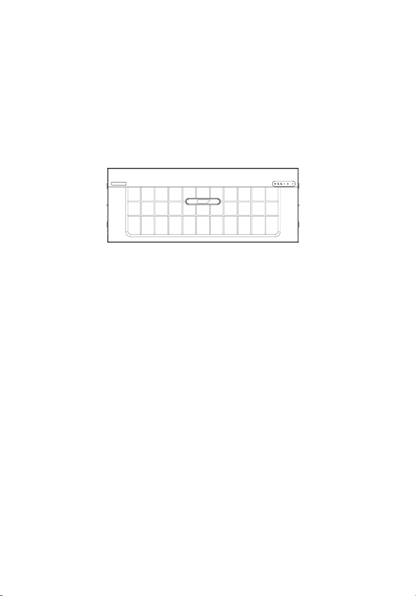
Front bezel
The front bezel provides an interface for system management via
status LED indicators. The light pipes on the backside of the front bezel
allow the system status LEDs to be monitored when the front bezel is
closed.
The front bezel is removable to allow access to server’s hard drives,
peripheral device, and control panel. For details on how to remove the
front bezel, see “To remove the front bezel” on page 41.
Page 27
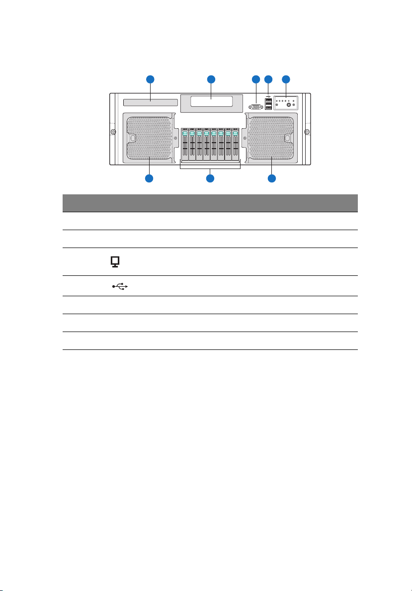
Front panel
9
A
B
G
Item Icon Component
A DVD drive bay
B 5.25-inch drive bays
C VGA/monitor port
D USB 2.0 ports
E Control panel
F Hot-swap system fan modules
G Hot-plug HDDs
C
E
D
FF
Page 28
10
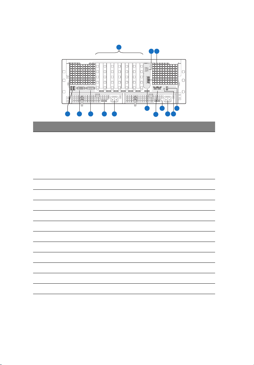
Rear panel
A
1743256
D
F
E
Item Component
A1 - A7 A1 Hot-plug PCI Express x8 slot
A2 Hot-plug PCI Express x8 slot
A3 PCI Express x8 slot
A4 PCI Express x8 slot
A5 PCI Express x8 slot (with x4 throughput)
A6 PCI Express x8 slot (with x4 throughput)
A7 PCI Express x8 slot (with x4 throughput)
B ARMC/3 R2 Ethernet port*
C I/O expansion module Ethernet ports
D USB 2.0 ports
H
G
B C
I N
K
L
M
J
1 System tour
E VGA/monitor port
F Serial port
G, K Power supply indicators
H, L AC input power connector
I I/O expansion module (optional)
J Gigabit LAN ports (10/100/1000 Mbps)
M System ID button
N System ID indicator
* Reserved for remote management of server. This requires installation of an ARMC/3 R2
module.
Page 29
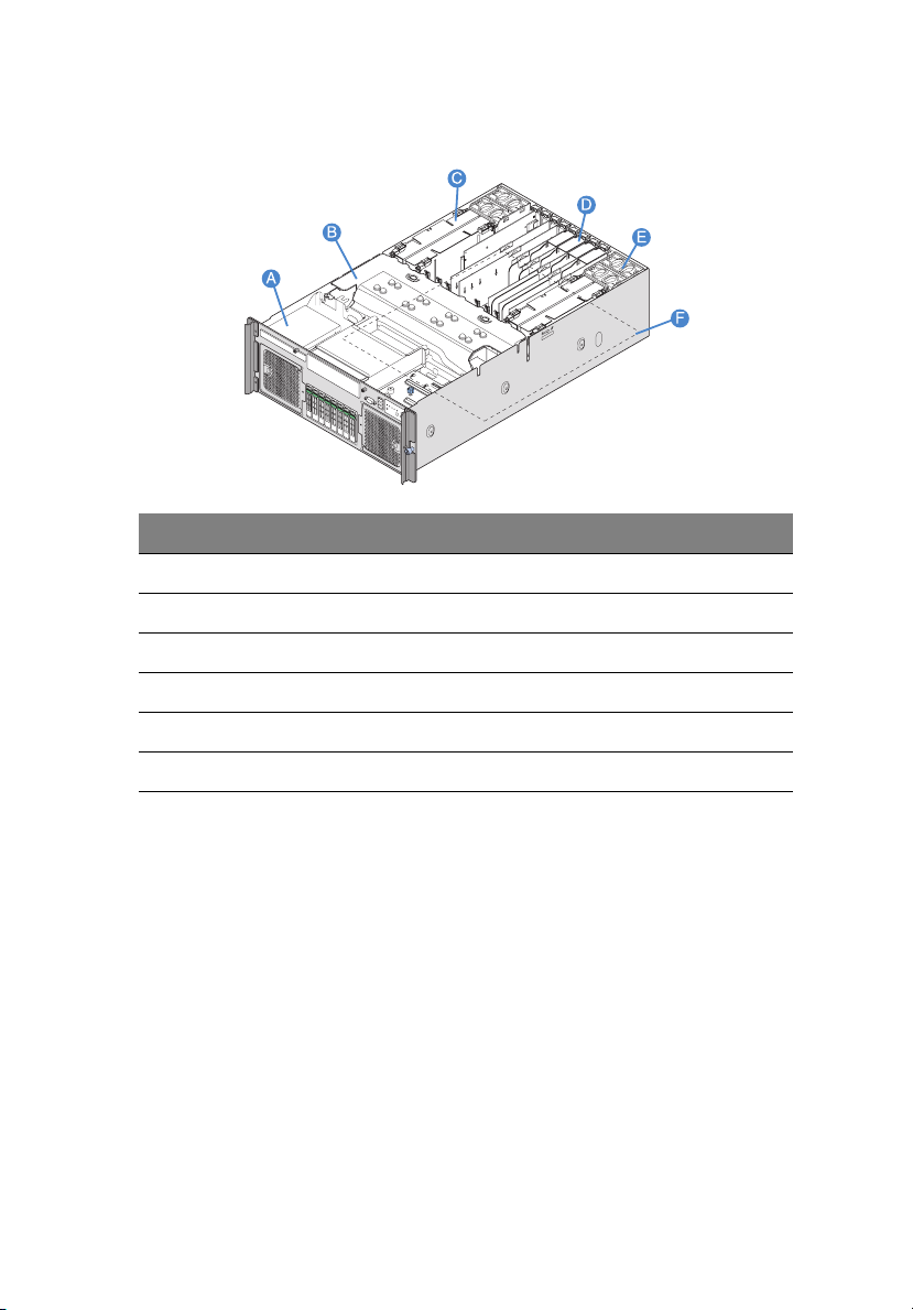
Internal components
Item Component
A DVD drive bay
B Processor air baffle
C Memory board
D Plastic PCI slot divider and PCI slots
11
E Rear system fan modules
F Mainboard
Page 30
12
1 System tour
System boards
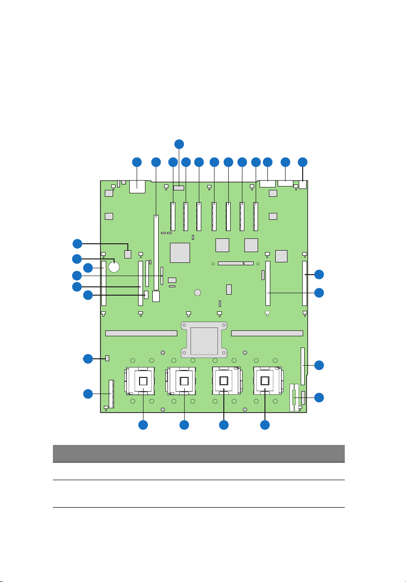
Mainboard
The mainboard becomes accessible once you open the system. It should
look like the figure shown below.
D
CC
BB
Z
Y
AA
X
W
V
A
B C E F G
U
H
J
I
T S R
M
L
K
N
O
P
Q
Item Description Item Description
A Dual Ethernet ports P Front panel connector
B I/O expansion module slot Q Power distribution board (PDB)
signal connector
Page 31

Item Description Item Description
13
C PCI Express x8 (with x4
throughput) - (slot 7)
D Serial port A (internal) S CPU socket 2
E PCI Express x8 (with x4
throughput) - (slot 6)
F PCI Express x8 (with x4
throughput) - (slot 5)
G PCI Express x8 (slot 4) V SAS module slot
H PCI Express x8 (slot 3) W Chassis intrusion
I Hot-plug PCI Express x8
(slot 2)
J Hot-plug PCI Express x8
(slot 1)
K Serial port B Z SATA connectors
L VGA port AA Memory board slot D
M USB 1 (top)
USB 2 (bottom)
N Memory board slot A CC Trusted Platform Module (U2D1)
O Memory board slot B
* Reserved for tape drives.
R CPU socket 1
T CPU socket 3
U CPU socket 4
X Internal USB port*
Y Memory board slot C
BB Real-time clock battery
Page 32

14
1 System tour
Memory board
The memory board connects to the mainboard through x16 PCI Express
slots.
D
F
IHG
Q
P
O
N
M
L
K
J
Item Description Item Description
A Power good indicator J DIMM 1 slot
B DIMM 1 fault indicator K DIMM 2 slot
B
E
A
C
C DIMM 2 fault indicator L DIMM 3 slot
D DIMM 3 fault indicator M DIMM 4 slot
E DIMM 4 fault indicator N DIMM 5 slot
F DIMM 5 fault indicator O DIMM 6 slot
G DIMM 6 fault indicator P DIMM 7 slot
H DIMM 7 fault indicator Q DIMM 8 slot
I DIMM 8 fault indicator
Page 33

Control panel
The Altos R920 system supports either the button control panel,
providing basic functionality, or the LCD control panel, which adds
additional server management features. Both control panels utilize a
combination of control buttons, status LED indicators, along with I/O
ports, to centralize system control, monitoring, and accessibility.
15
Page 34

16
Button control panel
Item Icon Component
A HDD (hard disk drive) activity indicator
1 System tour
B LAN1 status indicator displays network activity in either
C Status/fault indicator
D Power indicator
E System ID indicator
F System ID button
G Power button
H Reset button
LAN ports on the mainboard.
LAN2 status indicator displays network activity in either
LAN ports on the optional I/O expansion module.
Page 35

LCD control panel (optional)
Item Icon Component
A LCD display
B Scroll up button
C Scroll down button
D Back button
E Select button
F System ID indicator
17
G Power indicator
H Power button
I Status/fault indicator
J LAN1 status indicator displays network activity in either
LAN ports on the mainboard.
LAN2 status indicator displays network activity in either
LAN ports on the optional I/O expansion module.
K HDD (hard disk drive) activity indicator
L Reset button
Page 36

18
1 System tour
Control panel button function overview
The following table list and describe the function of the control
buttons available on the control panel.
Control button Function
NMI button Puts the server in a halt-state for diagnostic purposes
and allows you to issue a non-maskable interrupt.
After using the interrupt, a memory download can be
performed to determine the cause of the problem.
Reset button Reboots and initializes the system.
Power/sleep button Toggles the system power on and off. This button also
functions as a sleep button if enabled by an ACPIcompliant operating system.
System ID button Toggles the front panel ID LED and the mainboard
Scroll up button With an LCD control panel, use these navigation
Scroll down button
Back button
Select button
system ID LED on and off. The mainboard system ID
LED is visible through the rear of the chassis and
allows you to locate the server you’re working on
from behind a rack of servers.
buttons to do the following.
• Navigate through the menu options.
• Select an option in the menu and confirm your
selection.
Page 37

System LED indicators
This section describes the different LED indicators located on
• Control panel
• Hot-plug HDD carrier
• Hot-swap fan module
• Hot-plug power supply module
• LAN port
• Hot-plug PCI Express slot
• Memory board
19
Page 38

20
1 System tour
Control panel LED indicators
The following table list and describe the LED indicators available on
the mini or optional full-function control panel.
Item
AHDD
LED
indicator
activity
Color
Green On — HDD is installed and
Green Blinking — HDD is active.
Amber On — HDD or HDD slot
Amber Slow
Amber Fast
LED
status
blinking
(~1 Hz)
blinking
(~2.5
Hz)
System
status
— A predictive HDD or
— HDD rebuild is
Description
functioning correctly.
Note: LED may blink
if all drives are active
at the same time.
failure.
HDD slot failure or
rebuild is in process.
interrupted or
rebuild on empty
slot.
Page 39

21
LED
Item
indicator
B LAN1,
LAN2
status
C Status/
fault
Color
Green On • LAN1
Green Blinking Active Network access
— Off Idle No activity
·— Off Not Ready • AC power off
Green On Ready System booted and
Green Blinking Degraded • System is in a
Amber On Critical
LED
status
System
status
active
•LAN2
active
condition
Description
• Network activity
in either LAN
ports on the
mainboard.
• Network activity
in either LAN
ports on the
optional I/O
expansion
module.
• POST error
ready.
degraded state.
• Processor or DIMM
disabled.
• System failure.
• Critical power
supply, blower,
voltage, or
temperature
failure.
Amber Blinking Non-
critical
condition
• Redundant power
supply or blower
failure.
•Non-critical
blower, voltage,
and temperature
failure.
Page 40

22
1 System tour
Item
D Power — Off Power off System is not
E System ID Blue On — System identification
LED
indicator
Color
Green On Power on System has power
— Off S4/S5 System in ACPI S4 or
Green Blinking S1 System in ACPI S1
Green On S0 System in ACPI S0
— Off — Identification is
LED
status
System
status
Description
powered on.
applied to it.
S5 state (power off).
state (sleep mode).
state (legacy power
on).
is active.
disabled.
Hot-plug HDD carrier LED indicators
A
B
Item Color Status Description
A Amber Flashing HDD is not powered on and has a fault
condition.
Amber +
green
Alternate
flashing
• HDD is powered on and rebuilding RAID.
• HDD is powered on and has a fault
condition.
Page 41

Item Color Status Description
B Green On HDD is installed and working correctly.
Flashing HDD is active.
Off • No HDD is installed.
• HDD is initiated but has no current
activity.
Hot-swap fan module LED indicators
23
LED
indicator
Fan good — Off Fan normal operation.
Fan fault Amber On Fan failure (Non-critical condition).
Color Status Description
Page 42

24
1 System tour
Hot-plug power supply module LED indicators
Item
A Power good Green On System has power applied to it.
B Fault Amber On • Power rail failure.
C AC OK Green On AC power cord is plugged into an
LED
indicator
Color Status Description
• Power supply is in a latched
state.
active AC power source.
Page 43

LAN port LED indicators
25
A
B
Item
A Status Green On Network link is detected.
B Speed — Off 10 Mbps connection
LED
indicator
Color Status Description
Off No network connection.
Blinking Network connection in place.
Green On 100 Mbps connection
Amber On 1000 Mbps connection
Hot-plug PCI Express slot LED indicators
The PCI slots 1 and 2 have a LED indicator to display the PCI hot-plug
status.
LED
indicator
Power Off Power off All main rails are removed from the
Color Status Description
slot. Card can be inserted or removed.
Green, onPower on PCI slot 1 or 2 is powered on. Card
cannot be inserted or removed.
Green,
blinking
Power
transition
PCI slot 1 or 2 is in the process of
changing state. Card cannot be
inserted or removed.
Page 44

26
1 System tour
LED
indicator
Attention Off Normal Normal operation
Color Status Description
Amber, onAttention Power failure or operational problem
Amber,
blinking
Locate Slot is being identified.
at the slot.
Memory board LED indicators
The LEDs on the memory board indicate the status of the memory
board power and DIMM.
D
IHG
F
B
E
A
C
Item LED indicator Color Description
A Power good Green, onPower is detected.
The memory board power is good.
Off Power is not detected on all boards.
B-I DIMM 1 to 8
fault
Amber, onDIMM installed in DIMM slots is
malfunctioning and needs to be
replaced.
Off DIMM is functioning properly.
Page 45

System jumpers
A
C D
B
27
E
F
Item Name Location Default Settings
A Rolling BIOS J3D1 1-2 (Empty)
2-3 (Stuff)
B Password
disable or clear
C Clear CMOS/
NVRAM
DBMC force
update
J3C2 1-2 (Stuff)
2-3 (Empty)
J3C3 1-2 (Stuff)
2-3 (Empty)
J5C1 1-2 (Stuff)
2-3 (Empty)
Force other bank
Normal mode
Password protect
Password disabled/
cleared
Normal
Forced CMOS/
NVRAM clear
Disable BMC force
update
Enable BMC force
update
Page 46

28
Item Name Location Default Settings
1 System tour
E BMC flash write
protect
F Circuit breaker J6F1 1-2 (Empty)
J6D1 1-2 (Stuff)
2-3 (Empty)
2-3 (Stuff)
Disable flash write
protect
Enable flash write
protect
20 A/110 V (USA)
15 A/100 V (Japan)
Page 47

2 System setup
Page 48

This chapter gives you instructions on how to set up
the system. Procedures on how to connect
peripherals are also explained.
Page 49

Setting up the system
Pre-installation requirements
Selecting a site
Before unpacking and installing the system, select a suitable site for
the system for maximum efficiency. Consider the following factors
when choosing a site for the system.
• Near a grounded power outlet
• Clean and dust-free
• Stable surface free from vibration
• Well-ventilated and away from sources of heat
• Secluded from electromagnetic fields produced by electrical
devices such as air conditioners, radio and TV transmitters, etc.
Checking the package contents
Check the following items from the package:
• Acer Altos R920 system
• Acer EasyBUILDTM
• Acer eBusiness ValuePack
• Acer Altos R920 accessory box
31
If any of the above items are damaged or missing, contact your dealer
immediately.
Save the boxes and packing materials for future use.
Page 50

32
2 System setup
Connecting peripherals
Refer to the illustration below for specific connection instructions on
the peripherals you want to connect to the system.
110/220 V
Note: Consult the operating system manual for information on
how to configure the network setup.
110/220 V
Page 51

Turning on the system
After making sure that you have properly set up the system, applied
power, and connected all the necessary peripherals, you can now
power on the system.
1 Remove the front bezel.
2 Press the power button.
33
3 The system starts up and displays a welcome message on the
monitor. After that, a series of power-on self-test (POST) messages
appear. The POST messages indicate if the system is running well
or not.
Page 52

34
Note: If the system does not turn on or boot after pressing the
power button, go to the next section for the possible causes of the
boot failure.
2 System setup
If the POST finds any problems, the system will emit a beep code
followed by an error message displayed on the monitor. Aside from the
POST messages, you can determine if the system is in good condition
by checking if the following occurred.
• The power indicator on the control panel lights up green.
• The Num Lock, Caps Lock, and Scroll Lock indicators on the
keyboard light up.
Power-on problems
If the system does not boot after you have applied power, check the
following factors that might have caused the boot failure.
• The external power cable may be loosely connected.
Check the power cable connection from the power source to the
power cable socket on the rear panel. Make sure that the cable is
properly connected to the power source and to the power cable
socket.
• No power comes from the grounded power outlet.
Have an electrician check your power outlet.
• Loose or improperly connected internal power cables.
Check the internal cable connections. If you are not confident to
perform this step, ask a qualified technician to assist you.
Warning! Make sure all power cords are disconnected from
the electrical outlet before performing this task.
Note: If you have gone through the preceding actions and the
system still fails to boot, ask your dealer or a qualified technician
for assistance.
Page 53

35
Configuring the system OS
The Altos R920 system comes with Acer EasyBUILD that allows you to
conveniently install your choice of operating system. To start using
EasyBUILD, follow the steps below.
1 Locate the EasyBUILD DVD included in the system package.
2 With the system turned on, gently press the DVD drive Stop/Eject
button.
3 When the disc tray slides open, insert the EasyBUILD DVD with the
label or title side of the disc facing upward.
Note: When handling the disc, hold it by the edges to avoid
smudges or fingerprints.
4 Gently press the disc down to make sure that it is properly
inserted.
Caution! While pressing the disc, be careful not to bend the disc
tray. Make sure that the disc is properly inserted before closing
the disc tray. Improper insertion may damage both the disc and
the DVD drive.
5 Gently press the drive Stop/Eject button again to close the disc
tray.
6 The Acer EasyBUILD sequence begins. Follow all onscreen
instructions.
For more information, refer to the Acer EasyBUILD Installation guide.
Note: Windows or Linux OS CD is needed when you install the OS
with the EasyBUILD DVD.
Page 54

36
2 System setup
Turning off the system
There are two ways to turn off the server—via software or via
hardware. The software procedure below applies to a system running
on a Windows OS. For other OS shutdown procedures, refer to the
related user documentation.
To turn off the system via software:
1 Press Ctrl+Alt+Delete on the attached keyboard or click the Start
on the Windows taskbar.
2 Select Shut Down.
3 Select Shut down from the drop-down menu, then click OK.
To turn off the system via hardware:
If you cannot shut down the server via software, press the power
button for at least four seconds or until the server shuts down. Quickly
pressing the button may put the server in a Suspend mode only.
Page 55

3 System upgrade
Page 56

This chapter discusses the precautionary
measures and installation procedures you
need to know to upgrade the system.
Page 57

Installation precautions
Before you install any server component, we recommend that you read
the following sections. These sections contain important ESD
precautions along with pre-installation and post-installation
instructions.
ESD precautions
Electrostatic discharge (ESD) can damage the processor, disk drives,
expansion boards, motherboard, memory modules and other server
components. Always observe the following precautions before you
install a server component.
• Do not remove a component from its protective packaging until
you are ready to install it.
• Do not touch the component pins, leads, or circuitry.
• Components with a Printed Circuit Board (PCB) assembly should
always be laid with the assembly-side down.
• Wear a wrist grounding strap and attach it to a metal part of the
server before handling components. If a wrist strap is not
available, maintain contact with the server throughout any
procedure requiring ESD protection.
• Keep the work area free of nonconductive materials, such as
ordinary plastic assembly aids and foam packing.
39
Page 58

40
3 System upgrade
Pre-installation instructions
Perform the steps below before you open the server or before your
remove or replace any component.
Warning! Failure to properly turn off the server before you
start installing components may cause serious damage. Do
not attempt the procedures described in the following
sections unless you are a qualified service technician.
1 Turn off the system and all the peripherals connected to it.
2 Unplug the power cord from the power outlet.
3 Unplug all peripheral cables from the system.
4 Place the system unit on a flat, stable surface.
5 Open the system according to the instructions on page 41.
6 Follow the ESD precautions described in this section when
handling a server component.
Post-installation instructions
Perform the steps below after installing a server component.
1 See to it that all components are installed according to the
described step-by-step instructions.
2 Reinstall all hardware structure or cable that have been previously
removed.
3 Reinstall the top cover.
4 Reinstall the front bezel.
5 Reconnect the necessary cables.
6 Turn on the system.
Page 59

Opening the server
Caution! Before you proceed, make sure that you have turned
off the system and all peripherals connected to it. Read the “Preinstallation instructions” section on page 40.
You need to open the server before you can install additional
components. The front bezel and top cover are removable to allow
access to the system’s internal components. Refer to the following
sections for instructions.
Removing and installing the front bezel
To remove the front bezel:
Grasp the front bezel at outer edge and pull straight out.
41
Page 60

42
To install the front bezel:
Slide the front bezel onto the chassis.
3 System upgrade
Page 61

43
Removing and installing the top cover
To remove the top cover:
1 Perform the pre-installation instructions described on page 39.
2 Loosen the two captive screws located on the faceplate of the
chassis (A).
3 Slide the top cover toward the back of the chassis until the tabs on
the cover disengage with the slots on the chassis.
4 Lift the top cover away from the server and put it aside for
reinstallation later (B).
Page 62

44
3 System upgrade
To install the top cover:
1 Perform the pre-installation instructions described on page 39.
2 Place the top cover on the chassis so that the tabs on the cover
align with the slots on the chassis (A).
3 Slide the top cover toward the front of the chassis until it is fully
closed.
4 Tighten the captive screws on the faceplate of the chassis (B).
A
B
Page 63

45
Removing and installing the processor air baffle
To remove the processor air baffle:
You will need to remove the processor air baffle to perform the
following procedures.
• Removing and installing a heat sink
• Removing and installing a processor
• Removing and installing the SAS module
• Removing and installing the RAID activation key and RAID cache
• Removing and installing the RAID BBU
1 Perform the pre-installation instructions described on page 39.
2 Disconnect the 100-pin cable from the mainboard connector on
the front panel I/O board then move cable over the side of the
chassis.
3 Disconnect any cables attached to the device in the 5.25-inch
peripheral bay.
4 Insert your fingers into the holes on the top of the baffle.
5 Pull the baffle up and back to disengage the baffle from the two
sheet-metal tabs on front of the baffle.
6 Lift the baffle from the chassis.
Page 64

46
3 System upgrade
To install the processor air baffle:
1 Perform the pre-installation instructions described on page 39.
2 Insert the front of the processor air baffle (A) under the two metal
tabs at the front of the baffle (B), just below the SAS backplane
board. One tab is located on each side of the chassis.
A
B
B
Page 65

47
3 Lower the rear of the baffle into place (A), making sure the guides
on each side of the air baffle will correctly engage in the left and
right chassis slots (B).
A
A
B
B
A
B
4 Push down the air baffle to ensure it is fully seated.
5 Observe the post-installation instructions described on page 40.
Page 66

48
3 System upgrade
Configuring hot-pluggable components
Hot-pluggable components are the components that can be removed
and replaced while the system is powered on. For this server model, it
refers to the following components.
• Hard disk drive
• System fan assembly
• Power supply
• PCI card with OS hot-plug interface
Page 67

49
Removing and installing a hard disk drive
The system supports eight hot-plug drive carriers. Each carrier holds a
standard 2.5-inch SAS hard drive.
Note: Use only Acer-qualified HDDs. To purchase an HDD, contact
your local Acer representative.
Caution! To ensure proper airflow and server cooling, all drive
bays must contain either a carrier with a hard drive installed in it
or a hard disk carrier cover.
Determining drive status
Each HDD carrier features two status LED indicators to display the hard
drive status. If you are replacing a failed HDD, determine which drive
has failed by checking the drive status LED. For more information on
how to determine the drive status, refer to “Control panel LED
indicators” section on page 20.
To remove an HDD:
1 Observe the ESD precautions described on page 39.
2 Remove the front bezel. Perform the instructions described in “To
remove the front bezel” section on page 41.
3 If you are removing a failed HDD, determine which drive has failed
by checking the drive status LEDs.
4 Press the green HDD carrier latch (A).
Page 68

50
3 System upgrade
5 Pull the lever and slide the carrier from the chassis (B).
B
A
6 Place the HDD carrier on a clean, static-free work surface.
7 If you are replacing a hard disk, remove the four screws that secure
the hard disk to the HDD carrier, then remove the disk from the
HDD carrier.
8 Keep the screws for later HDD installation.
To install an HDD:
Note: To purchase an HDD carrier, contact your local Acer
representative.
1 Perform steps 1 through 5 of the “To remove an HDD” section on
page 49.
Page 69

2 Remove the four screws that secure the air baffle to the HDD
carrier (A).
3 Remove the air baffle from the HDD carrier (B).
4 Save the air baffle and screws for later use.
5 Remove the HDD from its protective packaging.
6 Install a hard disk on the HDD carrier, then secure it with the four
screws (A) that came with the HDD carrier (B).
B
A
51
7 With the lever still extended, slide the HDD carrier all the way into
the drive bay (A).
Page 70

52
3 System upgrade
8 Use the lever to push the HDD carrier until it docks into place, then
close the HDD carrier lever (B).
A
B
9 Setup the new hard drive’s RAID configuration.
For related instructions, refer to “RAID configuration utilities” on
page 177.
Removing and installing the system fan
The system has two cooling fan assemblies — two fan modules for each
assembly — located on the front panel and four cooling fans located at
the rear of the chassis.
Cautions:
• System fan hot-swap operations should be performed only if a
failure occurs in the fan assembly.
• System cooling is reduced during the fan replacement process. Do
not leave a system fan removed for longer than two minutes.
• Do not touch the fan blades while they are turning.
Page 71

53
Determining fan status
Each fan or fan assembly has an amber LED to indicate a failed fan
condition. If the amber LED is on, the fan assembly needs to be
replaced. The LED remains off during normal operation.
To remove the front system fan assembly:
1 Observe the ESD precautions described on page 39.
2 Remove the front bezel. Perform the instructions described in “To
remove the front bezel” section on page 41.
3 Locate the fan assembly you are replacing. If a fan in the assembly
has failed the amber LED will be lit (A).
4 Press the green button on the front of the fan assembly to release
the handle (B).
5 Use the handle to pull the fan from the system (C).
To install the front system fan assembly:
Warning! To ensure proper system cooling, the replacement
of a failed system fan module should be completed within
one minute.
1 If necessary, remove the old front system fan assembly. See
previous section.
2 Slide the new fan into the fan bay (A).
Page 72

54
3 System upgrade
3 Push the handle closed until it clicks into place (B).
To remove a rear system fan:
1 Perform the pre-installation instructions described on page 39.
2 Locate the fan assembly you are replacing. If a fan in the assembly
has failed the amber LED will be lit.
3 Grasp the fan by the finger holes and squeeze together, then lift
the fan upward.
Page 73

To install a rear system fan:
Warning! To ensure proper system cooling, the replacement
of a failed system fan module should be completed within
one minute.
1 If necessary, remove the old rear system fan. See previous section.
2 Lower the new fan into the fan bay.
3 Push down on the fan until it clicks into place.
55
Page 74

56
3 System upgrade
Removing and installing a power supply
The server has two power supply bays on the rear panel that accept
hot-swap redundant power supply modules. The system ships out with
at least one power supply module installed.
Power supply redundancy is available if two power supplies are
installed. A redundant power configuration enables a fully-configured
system to continue running even if one power supply module fails.
WARNING! To reduce the risk of personal injury or damage to
the equipment, the installation of power supply modules
should be referred to individuals who are qualified to service
server systems and are trained to deal with equipment capable
of generating hazardous energy levels.
WARNING! To reduce the risk of personal injury from hot
surfaces, observe the thermal labels on each power supply
module. You can also consider wearing protective gloves.
WARNING! To reduce the risk of personal injury from electric
shock hazards, do not open the power supply modules. There
are no serviceable parts inside the module.
Caution! Electrostatic discharge can damage electronic
components. Make sure that you are properly grounded
before handling a power supply module.
Caution! The system operating voltage range is 110 to 240
VAC. Do not plug the power cord into an incorrect voltage
source.
Determining power supply status
The power supply module has three status LED indicators to display the
power supply status. If the center LED is lit, the power supply needs to
be replaced. For more information on how to determine the power
supply status, refer to “Hot-plug power supply module LED indicators”
section on page 24.
Page 75

To remove a power supply:
Caution: Power supply hot-swap operations should be performed
only if a failure occurs in the power supply.
1 Observe the ESD precautions described on page 39.
2 Remove the AC power cord from the power supply.
3 Press down on the latch to release the power supply handle (A).
4 Open the handle on the power supply (B).
5 Pull the power supply from the chassis and set it on a clean, static-
free surface (C).
57
A
B
C
Page 76

58
3 System upgrade
To install a power supply:
1 If necessary, remove the old power supply. See previous section.
2 With the handle in the open position, push the power supply in
the bay fully (A).
3 Rotate the handle to the closed position (B).
4 Tighten the thumbscrew to secure the power supply (C).
A
B
5 Plug the power cord into the AC receptacle on the power supply.
6 Verify that the LEDs on the power supply are functioning. Refer to
the “Hot-plug power supply module LED indicators” section on
page 24 for more information.
Page 77

59
Removing and installing a PCI card
Important: Only PCI add-in cards in PCI slots 1 and 2 are
hot-pluggable. If you are installing or removing a PCI card from
PCI slot 3 through 7, see page 82 for more information.
Caution: Expansion slot covers must be installed over all vacant
slots to maintain the electromagnetic emission characteristics of
the server and to ensure proper system cooling.
Determining PCI slot status
The PCI slots 1 and 2 have a LED indicator to display the PCI hot-plug
status. For more information on how to determine the slot status, refer
to “Hot-plug PCI Express slot LED indicators” section on page 25.
To remove a hot-plug PCI card with OS hot-plug interface:
1 Perform the pre-installation instructions described on page 39.
2 If you are using a Microsoft Windows operating system, double-
click the Unplug/Eject icon in the taskbar to open the Unplug or
Eject Hardware menu.
3 Select the device to be removed and click Stop.
4 Make sure that the power LED on the rear of the PCI slot is turned
off before disconnecting any cables attached to the card.
Page 78

60
3 System upgrade
5 Open the yellow caution plate (A).
6 Rotate the slot retention latch on the rear of the card slot upward
(B).
7 Release the vertical edge of the card and pull it away from the
chassis (C).
B
PCI Add-in Card
A
PCI Caution Plate
C
8 Store the card in an antistatic protective wrapper.
9 If installing a new PCI card, see “To install a new PCI hot-plug PCI
card” section.
10 Observe the post-installation instructions described on page 40.
To remove a hot-plug PCI card with hardware interface:
1 Perform the pre-installation instructions described on page 39.
2 Press the attention button for this slot.
Page 79

61
Note: Press the attention button again within five seconds to
abort the hot-plug operation.
3 Make sure that the power LED on the rear of the PCI slot is turned
off before disconnecting any cables attached to the card.
4 Open the yellow caution plate (A).
5 Rotate the slot retention latch on the rear of the card slot upward
(B).
6 Release the vertical edge of the card and pull it away from the
chassis (C).
B
PCI Add-in Card
C
A
PCI Caution Plate
7 Store the card in an antistatic protective wrapper.
8 If installing a new PCI card, see “To install a new PCI hot-plug PCI
card” section.
9 Observe the post-installation instructions described on page 40.
Page 80

62
3 System upgrade
To install a new hot-plug PCI card:
1 If your server is operating, use your OS to power down the PCI slot.
2 Perform the pre-installation instructions described on page 39.
3 Open the yellow caution plate (A).
4 Rotate the slot retention latch on the rear of the card slot upward
(B).
5 Remove the PCI card from its protective packaging.
6 Align then insert the card into the selected slot. Make sure that
the card is properly seated (C).
B
PCI Add-in Card
A
PCI Caution Plate
C
7 Rotate the retention latch downward.
8 Connect any required cable to the card.
9 When using the hot-plug PCI card with OS hot-plug interface:
• Wait for the software user interface to appear on your
monitor and then confirm the device to be enabled.
• Wait for the power LED to turn on.
If using the hot-plug PCI card with hardware interface:
• Press the attention button for the slot. If you need to abort
the hot-plug operation, press the attention button again
within five seconds.
• Wait for power LED to turn on.
10 Observe the post-installation instructions described on page 40.
Page 81

Configuring cold-pluggable components
Cold-pluggable components are the components that require the
system to be powered down before you can remove or replace them.
The cold-pluggable components installed in the server include.
• DVD drive
• 5.25-inch drive
• Processor
• Memory board assembly
• DIMM module
•PCI card
• I/O expansion module
• ARMC/3 R2 module
•SAS module
• RAID activation key and RAID cache
• RAID BBU
63
Page 82

64
3 System upgrade
Removing and installing the DVD drive
To remove the DVD drive:
1 Perform the pre-installation instructions described on page 39.
2 Disconnect the power and SATA cables from the SATA-to-IDE
converter board on the rear of the media device (A).
3 Press the blue release latch on the media device carrier (B).
4 Slide the media device from the front opening in the faceplate of
the system (C).
5 Lift the rear right corner of the media device to remove it from the
carrier (D) and (E).
6 Remove the SATA-to-IDE converter board (F).
Page 83

7 Observe the post-installation instructions described on page 40.
To install the DVD drive:
1 Perform the pre-installation instructions described on page 39.
2 If necessary, remove the old DVD drive. See previous section.
3 Remove the new drive from its protective packaging.
4 Attach the SATA-to-IDE converter board to the new media device
(A).
5 Install the media device into the carrier (B).
6 Slide the carrier into the front opening in the chassis (C).
7 Plug the SATA and power cables into the converter board (D).
65
8 Observe the post-installation instructions described on page 40.
Page 84

66
3 System upgrade
Installing a 5.25-inch drive
The 5.25-inch drive bay allows you to install a tape drive to provide the
system with additional storage capacity.
To install a 5.25-inch drive:
1 Perform the pre-installation instructions described on page 39.
2 Push the tabs on both sides of the carrier filler panel (A).
3 Hold the tabs in while pulling the carrier filler panel from the bay
(B).
4 Remove the screws that attach the slide rails to the filler panel.
5 Attach the slide rails to the device, then secure it with screws you
removed earlier.
6 Attach the Y-power cable to the rear of the device.
Page 85

7 Slide the 5.25-inch peripheral device into the server until it clicks
into place.
8 Observe the post-installation instructions described on page 40.
67
Page 86

68
3 System upgrade
Upgrading the processor
The server supports up to four processors, the following models are
supported.
• Quad-core Intel Xeon processors 7300 series
• Dual-core Intel Xeon processors 7200 series
Processor configuration guidelines
Observe the following guidelines when replacing or installing a
processor.
• Use only Acer-qualified processors.
• The CPU 1 socket must always be populated. If no processor is
installed in this socket, the system will fail to boot.
• Before removing a processor, make sure to back up all important
system files.
• When installing a second, third, or fourth processor, make sure it
has same stepping and frequency specifications as the default
processor.
• Handle the processor and the heatsink carefully. Damage to either
may prevent the system from functioning properly.
• Caution! Make sure to install a processor thermal blank and a
heat sink to replace the thermal blank. Only power on a system
that has all four CPU sockets populated with heat sinks and/or
thermal blanks.
To install a new processor:
1 Perform the pre-installation instructions described on page 39.
Warning! The heat sink becomes very hot when the system
is on. NEVER touch the heat sink with any metal or with
your hands.
2 If necessary, remove the processor air baffle. Perform instructions
described in “To remove the processor air baffle” section on page
45.
Page 87

3 Remove the thermal blank.
(1) Loosen the four screws on the thermal blank.
(2) Pull the thermal blank away from the CPU socket.
Thermal
Blank
Server Board Cutaway
69
(3) Store the thermal blank in a protective bag.
4 Remove the new processor from its protective packaging.
5 Install the new processor.
(1) Pull the CPU socket retainer lever to a fully open position.
Page 88

70
3 System upgrade
(2) Position the processor over the socket, matching the two
triangle markers (A) and lining up the processor pins with the
socket (B).
(3) Press the retainer lever down to lock the processor in place.
6 Apply thermal grease.
Apply approximately 0.1 ml of the thermal grease compound to
the top of the processor.
7 Install the heat sink.
(1) Set the heat sink on the processor, aligning the four screws in
the heat sink with the screw sockets in the chassis.
Page 89

(2) Tighten the screws in the order shown, approximately one full
turn at a time until each is evenly tightened. Do not fully
tighten one screw at a time.
3
1
4
2
8 Observe the post-installation instructions described on page 40.
71
To r e mo ve a pr oce ss or:
Important: Before removing a processor from the mainboard,
make sure to create a backup file of all important data.
1 Perform the pre-installation instructions described on page 39.
Warning! The heat sink becomes very hot when the system
is on. NEVER touch the heat sink with any metal or with
your hands.
2 If necessary, remove the processor air baffle. Perform instructions
described in “To remove the processor air baffle” section on page
45.
3 If a heatsink is installed, remove the heat sink.
(1) Loosen the four screws on the heat sink in the order shown.
Page 90

72
3 System upgrade
(2) Pull the heat sink away from the CPU socket.
3
1
2
4
(3) Lay down the heat sink in an upright position—with the
thermal patch facing upward. Do not let the thermal patch
touch the work surface.
(4) Use an alcohol pad to wipe off the thermal grease from both
the heat sink and processor.
4 Remove the processor.
Warning! The processor becomes very hot when the system
is on. Allow it to cool off first before handling.
(1) Pull the CPU socket retainer lever to the fully open, upright
position.
Page 91

(2) Pull out the processor from the socket.
(3) Store it in an antistatic bag.
5 If you are not installing a new processor, reinstall the processor
thermal blank to maintain proper airflow within the chassis.
6 If you going to install a new processor, perform instructions
described in “To install a new processor” section.
7 Observe the post-installation instructions described on page 40.
73
Page 92

74
3 System upgrade
Removing and installing a memory board assembly
The server supports up to four memory boards. At least one memory
board and two FBDIMMs must be installed for the server to function.
Each memory board supports eight DIMM slots and a DIMM fault LED
for each FBDIMM that is used to report DIMM failures and error
conditions.
The supported memory board configurations are as follows.
• One memory board installed in memory board slot A, at the right
side of the system.
• Two memory boards, installed in memory board slots A and B, the
two boards at the right side of the system.
• All four memory boards, slots A, B, C, and D.
Important: Refer to the memory board installation order table
on page 166 when installing and removing memory boards.
Caution! Damage to the system occurs if power is not removed
from the system prior to removal or installation of memory
boards.
To remove the memory board assembly:
Note: If you remove a memory board from the server, you must
replace it with a replacement memory board.
1 Perform the pre-installation instructions described on page 39.
Page 93

2 Lift the latches on the memory board to disengage the memory
board from the mainboard (A).
3 Lift the memory board by the latches (B).
75
B
A
4 Observe the post-installation instructions described on page 40.
Page 94

76
3 System upgrade
To install the memory board assembly:
1 Perform the pre-installation instructions described on page 39.
2 Locate an empty memory board slot.
3 Add or replace memory DIMMs as needed. For instructions, see
“Installing and removing DIMM modules” section.
4 Lift the memory board latches to the fully open position.
5 Insert the memory board until latches are securely locked.
6 Observe the post-installation instructions described on page 40.
Page 95

77
Installing and removing DIMM modules
The server’s memory board supports eight DIMM slots. Each slot
supports 1 GB, 2 GB, and 4 GB DDR2-667 (PC2-5300) FBDIMM modules.
The server’s maximum memory capacity is 128 GB.
DIMM module configuration guidelines
Observe the following guidelines when replacing or installing DIMM
modules to the memory boards.
• The system supports up to four memory boards. At least one
memory board and two DIMMs must be installed for the server to
function. Each memory board must have a minimum of two
DIMMs installed.
• DIMMs must be installed in pairs. For example, DIMM slots 1 and 2,
DIMM slots 3 and 4, DIMM slots 5 and 6, DIMM slots 7 and 8
• DIMMs in the same memory board must be identical in size, speed,
and vendor.
• The system does not support mixed-sized DIMMs or DIMMs from
different vendors within the same memory board.
Warning! Functionality issues may be encountered if mixed
memory types are installed on the memory board.
• The system does not support combination of single-rank with dualrank memory.
• Use only DDR2 FBDIMMs. Other type of DIMMs will not fit into the
socket. Attempts to force a non-DDR2 FBDIMM into a socket will
damage and/or the socket or the DIMM.
• Hold DIMMs only by the edges. Do not touch the components or
gold edge connectors.
• Install DIMMs with gold-plated edge connectors only.
Important: Follow the DIMM module “FBDIMM module
population order” section on page 167 when installing and
removing DIMMs.
Page 96

78
3 System upgrade
DIMM population guidelines
The following rules apply when adding DIMMs to the memory boards.
• DIMMs must be populated beginning with memory board A,
DIMM slots A1 and A2.
• All DIMM slots must be populated with either a DIMM or a DIMM
thermal blank.
Important: DIMM thermal blanks must be installed to empty
DIMM slots to ensure proper system thermal performance.
Memory Board
Socket 8
Socket 7
Socket 6
Socket 5
Socket 4
Socket 3
Socket 2
Socket 1
FBDIMM
• FBDIMMs should be identical in terms of timing, technology, and
size.
Note: For additional memory configuration, see “Appendix B:
Memory configuration” section on page 163.
Page 97

To install DIMMs in the memory board:
Caution! Use extreme care when installing a DIMM. Applying too
much pressure can damage the connector. DIMMs are keyed and
can be inserted in only one way.
Note: DIMM slots on the memory board must be installed only in
certain configurations. Numbers next to DIMM slots correspond to
installation sequence. DIMMs may be installed in pairs.
1 Perform the pre-installation instructions described on page 39.
2 Remove the memory board assembly. Perform the instructions
described in “To install the memory board assembly” section on
page 76.
3 Remove the DIMM cover from the memory board.
(1) Press down on the hooks on the underside of the memory
board to disengage them (A).
(2) Lift the DIMM cover from the memory board (B).
79
B
A
4 Install DIMMs in the correct order. See “DIMM population
guidelines” section on page 78.
Page 98

80
3 System upgrade
5 Open the clips on the DIMM slot(s) (A).
6Align (B) then insert the DIMM into the socket (C).
7 Push down on the top edge of the DIMM. Make sure the holding
clips lock the DIMM in place (D).
8 Visually check that each latch is fully closed and correctly engaged
with each DIMM slot (E).
Note: The DIMM slot is slotted to ensure proper installation. If
you insert a DIMM but it does not fit easily into the socket, you
may have inserted it incorrectly. Reverse the orientation of the
DIMM and insert it again.
E
E
D
C
B
A
9 Install the DIMM cover to the memory board.
(1) Lower the DIMM cover over the DIMM slots.
(2) Line up the hooks in the cover with the notches on the bottom
edge of the memory board.
(3) Press the DIMM cover down until it clicks into place.
10 Install the memory board assembly. For instructions, see “To install
the memory board assembly” section on page 76.
11 Observe the post-installation instructions described on page 40.
Page 99

81
To remove DIMMs on the memory board:
Before you can install a new DIMM in a socket, remove first any
previously installed DIMM from that socket.
Important: Before removing any DIMM from the memory board,
make sure to create a backup file of all important data.
Caution! Use extreme care when removing DIMMs. Too much
pressure can damage the connector. Apply only enough pressure
on the plastic levers to release the DIMM.
1 Perform steps 1 to 3 described in the “To install DIMMs in the
memory board” section.
2 Press the holding clips on both sides of the DIMM slot outward to
release the DIMM.
3 Gently pull the DIMM upward to remove it from the socket.
4 Install the memory board assembly. For instructions, see “To install
the memory board assembly” section on page 76.
5 Observe the post-installation instructions described on page 40.
To reconfigure the system memory:
The system automatically detects the amount of memory installed. Run
the BIOS setup to view the new value for total system memory and
make a note of it.
Page 100

82
3 System upgrade
Removing and installing a non-hot-plug PCI card
PCI cards installed in slots 1 and 2 are hot-pluggable. If you are adding
or removing a card from one of these slots, you can do so without
powering down the server. For information, refer to page 59.
To remove a non-hot-plug PCI card:
Caution! Damage to the system occurs if power is not removed
from the system prior to removal or installation of non-hot-plug
boards.
1 Perform the pre-installation instructions described on page 39.
2 Disconnect any cables attached to the PCI card.
3 Perform steps 5 through 10 described in the “To remove a hot-plug
PCI card with OS hot-plug interface” section on page 59.
To install a non-hot-plug PCI card:
1 Perform the pre-installation instructions described on page 39.
2 Perform steps 2 to 8 described in the “To install a new hot-plug PCI
card” section on page 62.
 Loading...