

Page 1

Acer Altos R510 (DDR2)
User’s Guide
Page 2

Copyright © 20
All Rights Reserved.
Acer Altos R510
User’s Guide
1st Issue: December 200
Changes may be made periodically to the information in this publication without obligation
to notify any person of such revision or changes. Such changes will be incorporated in new
editions of this manual or supplementary documents and publications. This company makes
no representations or warranties, either expressed or implied, with respect to the contents
herein and specifically disclaims the implied warranties of merchantability or fitness for a
particular purpose.
Record the model number, serial number, purchase date, and place of purchase information in
the space provided below. The serial number and model number are recorded on the label
affixed to your computer. All correspondence concerning your unit should include the serial
number, model number, and purchase information.
No part of this publication may be reproduced, stored in a retrieval system, or transmitted, in
any form or by any means, electronic, mechanical, photocopy, recording, or otherwise,
without the prior written permission of Acer Incorporated.
05 Acer Incorporated
(DDR2)
5
Model Number : _________________________________
Serial Number: ___________________________________
Purchase Date: ___________________________________
Place of Purchase: ________________________________
Acer and the Acer logo are registered trademarks of Acer Inc. Other company’s product
names or trademarks are used herein for identification purposes only and belong to their
respective companies.
Page 3

iii
Notices
FCC notice
Class A devices do not have an FCC logo or FCC IDE on the label. Class
B devices have an FCC logo or FCC IDE on the label. Once the class of
the device is determined, refer to the following corresponding
statement.
Class A equipment
This device has been tested and found to comply with the limits for a
Class A digital device pursuant to Part 15 of the FCC Rules. These limits
are designed to provide reasonable protection against harmful
interference when the equipment is operated in a commercial
environment. This device generates, uses, and can radiate radio
frequency energy, and if not installed and used in accordance with the
instructions, may cause harmful interference to radio communications.
Operation of this device in a residential area is likely to cause harmful
interference in which case the user will be required to correct the
interference at his own expense.
However, there is no guarantee that interference will not occur in a
particular installation. If this device does cause harmful interference to
radio or television reception, which can be determined by turning the
device off and on, the user is encouraged to try to correct the
interference by one or more of the following measures:
• Reorient or relocate the receiving antenna
• Increase the separation between the device and receiver
• Connect the device into an outlet on a circuit different from that
to which the receiver is connected
• Consult the dealer or an experienced radio/television technician
for help
Shielded cables
All connections to other computing devices must be made using
shielded cables to maintain compliance with FCC regulations.
Page 4
iv
Peripheral devices
Only peripherals (input/output devices, terminals, printers, etc.)
certified to comply with the Class A or Class B limits may be attached to
this equipment. Operation with noncertified peripherals is likely to
result in interference to radio and TV reception.
Caution: Changes or modifications not expressly approved by
the manufacturer could void the user’s authority, which is granted
by the Federal Communications Commission, to operate this
server.
Use conditions
This part complies with Part 15 of the FCC Rules. Operation is subject to
the following two conditions: (1) this device may not cause harmful
interference, and (2) this device must accept any interference received,
including interference that may cause undesired operation.
Canadian users
This Class A/Class B digital apparatus meets all requirements of the
Canadian Interference-Causing Equipment Regulations.
Laser compliance statement
The CD-ROM drive in this server is a laser product. The CD-ROM drive’s
classification label (shown below) is located on the drive.
CLASS 1 LASER PRODUCT
CAUTION: INVISIBLE LASER RADIATION WHEN OPEN. AVOID
EXPOSURE TO BEAM.
Page 5

Important safety instructions
Read these instructions carefully. Save these instructions for future
reference.
1 Follow all warnings and instructions marked on the product.
2 Unplug this product from the wall outlet before cleaning. Do not
use liquid cleaners or aerosol cleaners. Use a damp cloth for
cleaning.
3 Do not use this product near water.
4 Do not place this product on an unstable cart, stand, or table. The
product may fall, causing serious damage to the product.
5 Slots and openings on the back or bottom side of the chassis are
provided for ventilation; to ensure reliable operation of the
product and to protect it from overheating, these openings must
not be blocked or covered. The openings should never be blocked
by placing the product on a bed, sofa, rug, or other similar surface.
This product should never be placed near or over a radiator or
heat register, or in a built-in installation unless proper ventilation
is provided.
6 This product should be operated from the type of power indicated
on the marking label. If you are not sure of the type of power
available, consult your dealer or local power company.
7 Do not allow anything to rest on the power cord. Do not locate
this product where persons will walk on the cord.
8 If an extension cord is used with this product, make sure that the
total ampere rating of the equipment plugged into the extension
cord does not exceed the extension cord ampere rating. Also,
make sure that the total rating of all products plugged into the
wall outlet does not exceed the fuse rating.
9 Never push objects of any kind into this product through chassis
slots as they may touch dangerous voltage points or short out
parts that could result in a fire or electric shock. Never spill liquid
of any kind on the product.
10 Do not attempt to service this product yourself, as opening or
removing covers may expose you to dangerous voltage points or
other risks. Refer all servicing to qualified service personnel.
11 Unplug this product from the wall outlet and refer servicing to
qualified service personnel under the following conditions:
v
Page 6

vi
a When the power cord or plug is damaged or frayed
b If liquid has been spilled into the product
c If the product has been exposed to rain or water
d If the product does not operate normally when the operating
instructions are followed. Adjust only those controls that are
covered by the operating instructions since improper
adjustment of other controls may result in damage and will
often require extensive work by a qualified technician to
restore the product to normal condition.
e If the product has been dropped or the cabinet has been
damaged
f If the product exhibits a distinct change in performance,
indicating a need for service.
12 Replace the battery with the same type as the product's battery we
recommend. Use of another battery may present a risk of fire or
explosion. Refer battery replacement to a qualified service
technician.
13 Warning! Batteries may explode if not handled properly. Do not
disassemble or dispose of them in fire. Keep them away from
children and dispose of used batteries promptly.
14 Use only the proper type of power supply cord set (provided in
your accessories box) for this unit. It should be a detachable type:
UL listed/CSA certified, type SPT-2, rated 7A 125V minimum, VDE
approved or its equivalent. Maximum length is 15 feet (4.6
meters).
Page 7

Notices iii
FCC notice iii
Class A equipment iii
Shielded cables iii
Peripheral devices iv
Use conditions iv
Canadian users iv
Laser compliance statement iv
Important safety instructions v
1 System information 1
Product briefing 3
Processor 3
Memory subsystem 3
Storage 4
Graphics interface 4
Networking 4
I/O ports 4
Caring features 5
Product specification summary 6
2 System tour 7
System board 9
Connector and Header Locations 9
Configuration Jumpers 11
Serial Port Configuration Jumper 12
BIOS Select Jumper 13
Back Panel Connectors 14
External and internal structure 16
Front view (with bezel) 16
Front view (w/o bezel) 16
Front panel 17
Front Panel LED and Buttons description 17
Control Button Functions 18
LED Indicator Status 18
Rear view 20
Optional Peripherals 21
Internal components 22
Contents
3 Getting Started 23
Setting up the system 25
Preinstallation requirements 25
Page 8

Selecting a site 25
Checking the package contents 25
System startup 26
Turning on the system 26
Turning off the system 26
Power-on problems 27
4 Configuring the system 29
Upgrading the system 31
Installation precautions 31
ESD precautions 31
Preinstallation instructions 31
Post-installation instructions 32
Opening the server 33
Before opening the server 33
Removing the Chassis Cover 33
Installing the Chassis Cover 35
Removing and Installing the Front Bezel 36
Removing the Front Bezel 36
Installing the Front Bezel 36
Removing and Installing the Processor Air Duct 37
Removing the Processor Air Duct 37
Installing the Processor Air Duct 37
Removing and Installing the Air Baffle 38
Removing the Air Baffle 38
Installing the Air Baffle 40
Installing and Removing a Hard Disk Drive 41
Installing a Fixed SATA Hard Disk Drive 41
Removing a Fixed SATA Hard Disk Drive 46
Installing a SATA or SCSI Hot-swap Hard Disk Drive 48
Removing a SATA or SCSI Hot-swap Hard Disk Drive 50
Installing or Removing a Floppy Drive 52
Installing a Floppy Drive into Slimline Bay
(Backplane Installed) 52
Removing a Floppy Drive from the
Slimline Bay (Backplane Installed) 55
Installing a Floppy Drive into Slimline Bay
(No Backplane Installed) 55
Removing a Floppy Drive from the Slimline Bay
(No Backplane Installed) 60
Installing a Floppy Drive into the Converted
Hard Drive Bay (Back plane Installed) 61
Removing a Floppy Drive from the
Converted Hard Drive Bay 64
Installing or Removing a DVD/CD-RW or CD-ROM Drive 66
Page 9

Installing a DVD/CD-RW or CD-ROM Drive into
Slimline Bay (Backplane Installed) 66
Removing a DVD/CD-RW or CD-ROM Drive
from the Slimline Bay (Backplane Installed) 68
Installing DVD/CD-RW or CD-ROM Drive into
Slimline Bay (No Backplane Installed) 69
Installing and Removing a PCI Riser Connector 72
Installing a PCI Riser Connector 72
Removing a PCI Riser Connector 74
Installing and Removing a PCI Add-in Card 76
Installing a PCI Add-in Card 76
Removing a PCI Add-in Card 77
Installing and Removing the SATA or SCSI
Backplane (Optional) 79
Removing the SATA or SCSI Backplane 79
Installing the SCSI or SATA Backplane 80
Processor Installation and Upgrade 83
Installing or Replacing the Processor 83
Installing the Processor 83
Installing the Heat Sink(s) 85
Removing a Processor 86
Memory Installations and Upgrade 87
Upgrading the system memory 87
Memory Sparing 89
Installing and Removing Memory 90
Installing DIMMs 90
Removing DIMMs 91
5 BIOS setup 93
Using the BIOS Setup Utility 95
Entering BIOS 95
If You Cannot Access Setup 95
Setup Menus 95
BIOS Setup Utility 96
BIOS Setup Keyboard Command Bar Options 97
Main 99
Advanced 101
Upgrading the BIOS 138
Preparing for the Upgrade 138
Recording the Current BIOS Settings 138
Obtaining the Upgrade 139
Upgrading the BIOS 139
Clearing the Password 139
Clearing the CMOS 140
Page 10

6 Troubleshooting 143
Resetting the System 145
Problems following Initial System Installation 145
First Steps Checklist 145
Hardware Diagnostic Testing 146
Verifying Proper Operation of Key System Lights 147
Confirming Loading of the Operating System 147
Specific Problems and Corrective Actions 147
Power Light Does Not Light 148
No Characters Appear on Screen 148
Characters Are Distorted or Incorrect 149
System Cooling Fans Do Not Rotate Properly 150
Diskette Drive Activity Light Does Not Light 150
CD-ROM Drive or DVD/CD-RW Drive Activity
Light Does Not Light 150
Cannot Connect to a Server 151
Problems with Network 151
System Boots when Installing PCI Card 152
Problems with Newly Installed Application
Software152
Problems with Application Software that
Ran Correctly Earlier 152
Devices are not Recognized under
Device Manager (Windows* Operating System) 153
Hard Drive(s) are not recognized 153
Bootable CD-ROM Is Not Detected 154
Appendix A: Management software installation 157
Installing ASM 159
System requirements 159
ASM Agent 159
ASM Console 159
System setup 159
Installing ASM Agent (Windows version) 159
Installing ASM Console (Windows version) 160
Installing ASM Agent (Linux version) 160
Appendix B: Tool-less rail kit installation 163
Tool-less rail kit installation 165
Setting the Multi-Pin Adapters for Rack Type 165
Installing the Slide Rails into the Rack 166
Installing the Component into the Slide Rails 168
Cable Management ARM installation 169
Page 11

Required Installation Position of the CMA 170
Installing the CMA on the Slide Rails 171
Placing and Securing Cabling Within the CMA 172
General Safety Information 173
Appendix C: Sensor Table 175
Sensor Table 177
Appendix D: SATA RAID Configuration 179
Configuring the onboard SATA RAID 181
How to enable the onboard SATA RAID function 181
Loading the BIOS default setting 181
Enabling the onboard SATA RAID function 181
How to create RAID 1 volume 181
Enter the onboard SATA RAID Configuration
Utility 181
Loading onboard SATA RAID default setting 181
Creating RAID 1 volume 182
Initialising RAID Volume 182
Saving and Exiting the Embedded RAID
Configuration Utility 183
Index 185
Page 12

Page 13

1 System
information
Page 14

The Acer Altos R510 is a rack optimised dual
processor system loaded with features. The
system uses next generation technology to
offer excellent performance for cost sensitive
applications.
Page 15
Product briefing
This section provides basic information concerning the configuration
of your Altos R510 system.
Processor
• Single or dual Intel® XeonTM processors with 800 MHz FSB
TM
• CPU Hyper-Threading
• Supports Extended memory 64bit technology (EM64T)
Memory subsystem
• Six (184 - pin) DIMM slots
• DDR2 400 MHz registered memory modules supported
• Maximum upgrade - 12 GB
• 2-way memory interleaving supported
• SDDC (Single Device Data Correction) for memory error detection
and correction of any number of bit failures in a single x4 memory
device
• Memory sparing technology
• When memory sparing is enabled, the spare DIMM will not be
detected by OS
• The sparing DIMM will be reserved for standby purposes and
cannot be accessed by the system
• Please refer to page116 "Memory Configuration Sub-menu
Selections" for more information about configuring the memory
sparing in the BIOS Setup utility
Technology support
1
3
1
For example, if six 1GB DIMMs are installed (6 GB memory) only
4GB of memory (in DIMM 1B, 1A, 2B, 2A) can be accessed by the
system. Memory in DIMM 3B and DIMM 3A would be reserved as
spare DIMMs
Caution! When using multiple memory modules it is
recommended that you AVOID using modules from different
manufacturers or that run at different speeds from each other.
Page 16
4
Warning! Functionality issues may be encountered if mixed
memory types are installed on the same server board. DIMM
modules of identical type, banking and stacking technology, and
vendor should be installed in the Altos R510.
1 System information
Storage
• Slim-type IDE CD-ROM/DVD-ROM drive
• Slim-type 3.5 inch Floppy disk drive (optional)
• Support for three (max) SCSI hard disk drives 300 * 3 = 900GB or
three SATA hard disk drives 400 * 3 = 1.2TB
Warning: If FDD and CD-ROM are installed, R510 would support 2
hard disk drives only.
Graphics interface
• On-board ATI Rage XL video controller with 8MB SDRAM
Networking
• Two Integrated Gigabit Ethernet connections
• Intel 82541PI Gigabit Ethernet LAN controller
• Marvell 88E8050 Gigabit Ethernet LAN Controller
I/O ports
•Front
• One USB 2.0 port
• One SVGA video port
•Rear
• Two USB 2.0 port
• Two PS/2 ports (keyboard/mouse)
• Two LAN ports (RJ-45)
• One SVGA video port
Page 17

Serial ATA ports
• Two SATA ports
Service ID
• Front service ID button
• Front and rear service ID LED
Operating Systems supported
• Microsoft® Windows® Server 2003
• Red Hat Enterprise Linux 3.0/4.0
• Novell NetWare 6.5
• SCO Unixware 7.1.4
• SCO OpenServer 5.0.7
RAID (Optional)
• Embedded SATA Software RAID 0,1 supported
Caring features
5
Part of Acer’s mission, as a company that cares about its end users, is to
provide features that make operation, maintenance, and upgrading
your system simpler and faster. The Altos R510 is no exception to this
rule. The following features and options are provided.
• Cost efficient operation in a value oriented package
• Tool-less design
• Front accessible USB and VGA ports
TM
•Acer EasyBUILD
• Acer Server Manager (ASM) suite of comprehensive management
tools
• Flexibility for future expansion
for efficient system setup and installation
Page 18

6
1 System information
Product specification summary
Highlighted below are the system’s key features:
• Single or dual Intel
Technology
• 800 MHz FSB supports processor speeds from 3.6 GHz and above
®
•Intel
•Intel® E7320 Memory Controller Hub (MCH)
•Intel® 6300ESB I/O Controller Hub (ICH)
• Supports two PCI riser cards
• Low Profile: One 66/66MHz/3.3V PCI-X slot
• One full height riser slot supporting one of two riser card
• Option 1: One 64-bit/66MHz/3.3V PCI-X slot
• Option 2: One (x4) PCI-Express slot
• Six DIMM sockets supporting DDR2 400 registered ECC modules
• Media storage
• Optional slim-type 3.5 inch 1.44 MB floppy drive or Optical drive
• Additional media storage capacity
• Support for three 3.5 Inch SATA, or SCSI hard disk drives
• External ports
• PS/2 keyboard and mouse ports • Two LAN (RJ-45) ports
• Three USB ports (1 front, 2 rear) • 2 SVGA video ports (1
E7320 chipset consisting of:
options:
for a maximum memory capacity of 12 GB
®
XeonTM processor supporting Hyper-Threading
front, 1 rear
• Power supply unit (PSU)
• One 450W power supply
• Chassis Intrusion
• Chassis intrusion switch
• Lock attach point for chassis cover
• Up to five system fans
• Four dual rotor plus one single rotor system fans
• Tool less fan replacement
•LEDs
• Standard Control Panel: NIC1 Activity, NIC2 Activity & Power /
Sleep
• System Status LEDs can be viewed with bezel closed
•Service ID
Page 19

2 System tour
Page 20

This chapter provides locations of various
components and ports and instructions on
how to set up the system.
Page 21
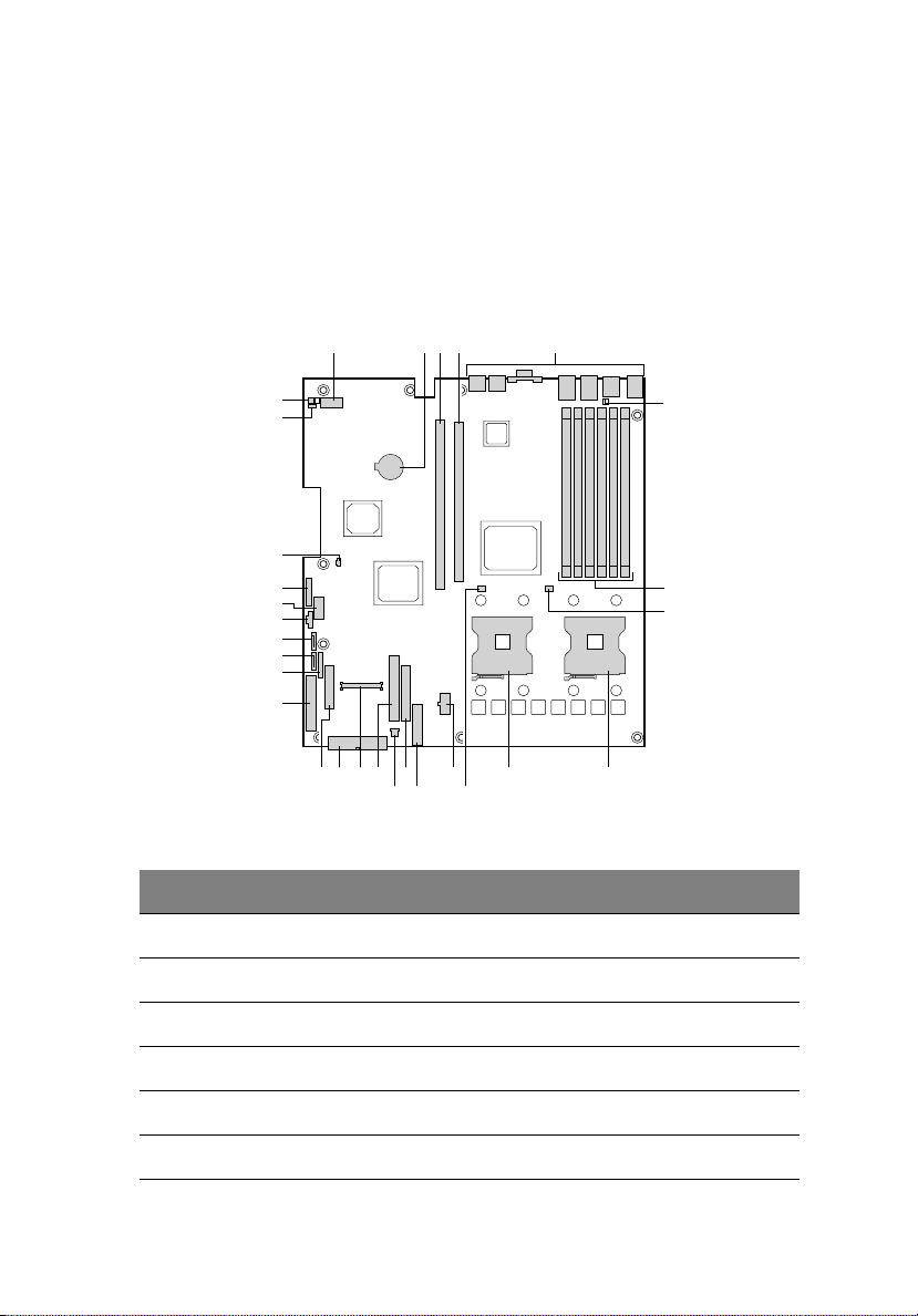
System board
Connector and Header Locations
The mainboard of the R510 becomes accessible once you open the
system. The figure below is provided to help you indentify and locate
connectors, slots and ports.
A B C E
D
9
CC
BB
AA
Z
Y
X
W
V
U
T
RS
PON
Q
K
M
Item Description
A Serial Port A
B Battery
C Full-height PCI slot
F
G
H
IJL
D Low-profile PCI slot
E Back panel I/O ports
F serial port selection jumper
Page 22

10
Item Description
G DIMM sockets (DIMM 1B, 1A, 2B, 2A, 3B, and 3A)
H Processor 1 fan header
I Processor 1 socket
J Processor 2 socket
K Processor 2 fan header
L +12V processor power connector
M Fan board connector
N Floppy connector
O PCI fan connector
P IDE connectors
Q 100-pin Floppy/Front Panel/ATA connector
R Main power connector
2 System tour
S 50-pin front panel connector
T 34-pin front panel connector
U Configuration jumpers
V SATA 1 connector
W SATA connector
X Power supply connector
Y OEM RMC connector
Z Power supply connector
AA IDE power connector
BB BIOS Select jumper
CC Chassis intrusion header
Page 23
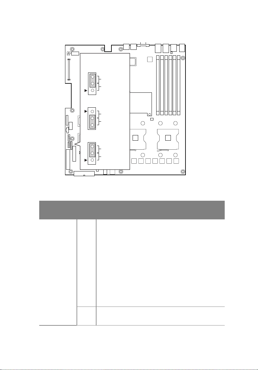
Configuration Jumpers
J1H2, J1H3, J1H5
J1H2 Pass Clr
3
Protect
2
Erase
J1H3 Rcvr Boot
Recovery Boot
2
Normal Boot
3
J1H5 CMOS Clr
3
BMC Control
2
Force Erase
11
Jumper
Name
J1H2
Password
Clear
J1H3
Recovery
Boot
Pins What happens at system reset??
1-2 If these pins are jumpered, administrator and user
passwords will be cleared on the next reset. These
pins should not be jumpered for normal operation.
2-3 These pins should be jumpered for normal system
operation
1-2 If these pins are jumpered, the system will attempt
to recover the BIOS by loading the BIOS code into
the flash device from a floppy disk. This jumper is
typically used when the BIOS has become corrupted.
These pins should not be jumpered for normal
operation.
2-3 These pins should be jumpered for normal system
operation.
Page 24
12
2 System tour
Jumper
Name
J15H CMOS
Clear
Pins What happens at system reset??
1-2 If these pins are jumpered, the CMOS settings will
be cleared on the next reset. These pins should not
be jumpered for normal operation.
2-3 These pins should be jumpered for normal system
operation.
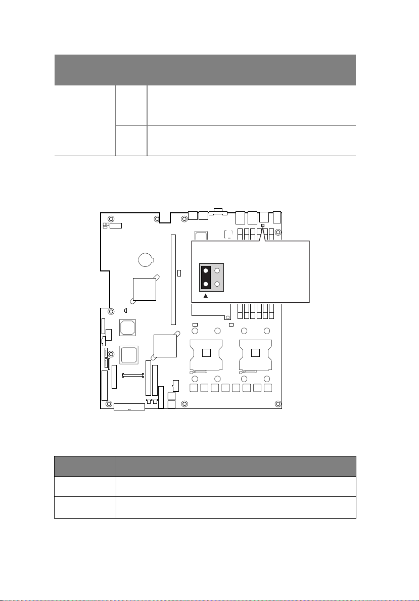
Serial Port Configuration Jumper
J8A3
34
1-3: DCD to DTR (Defa
2-4: DSR to DTR
2
TP00944
Pins What happens at system reset??
1-3 Serial port is configured for DCD to DTR (default)
2-4
Serial port is configured for DSR to DTR
Page 25
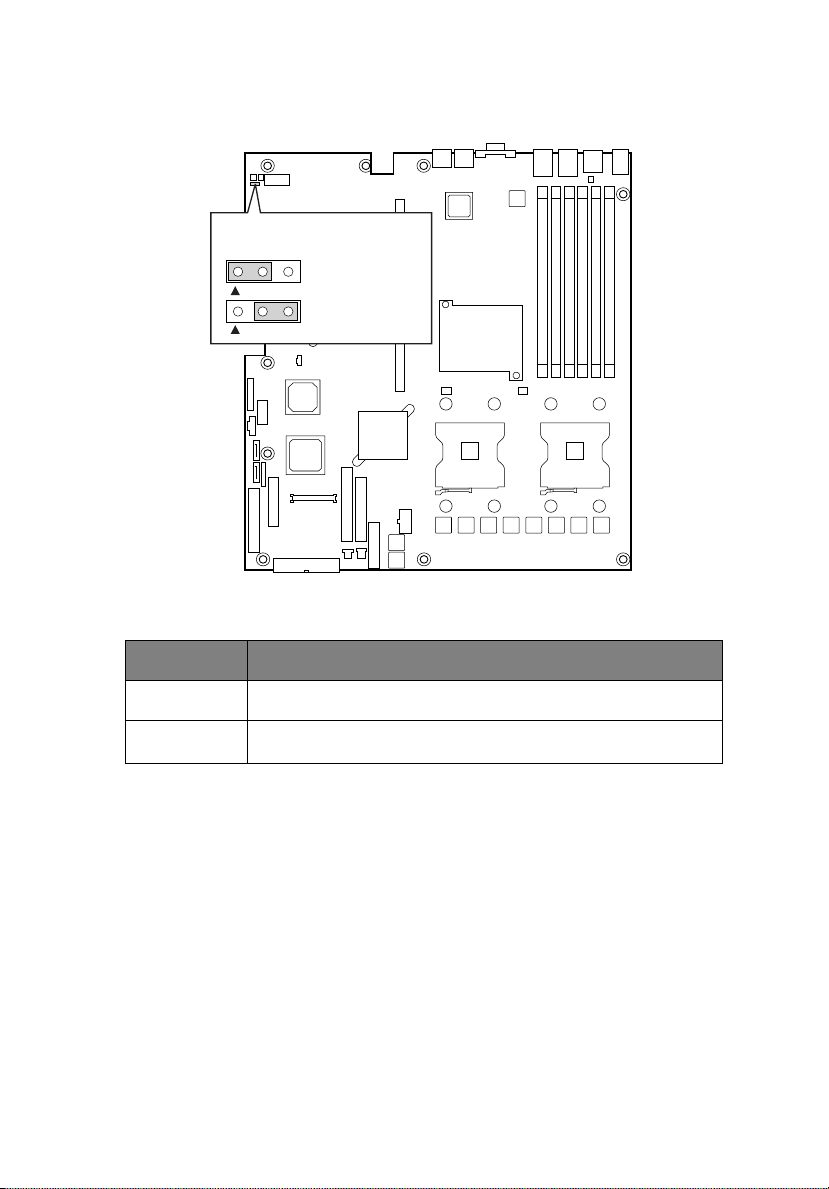
BIOS Select Jumper
J1A4
BIOS Select
1-2: Normal
Operation (Default)
3
2-3: Force to
Lower Bank
3
13
Pins What happens at system reset??
1-2 System is configured for normal operation
2-3
Force BIOS to lower bank
Page 26
14
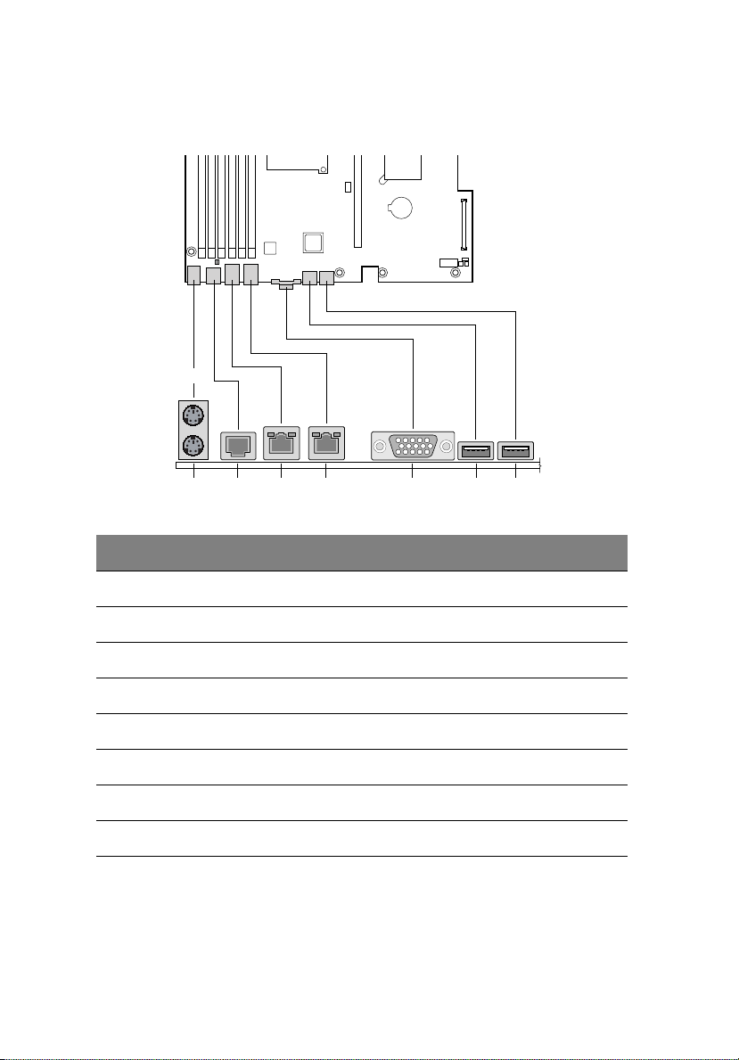
Back Panel Connectors
A
Item Description
2 System tour
FC D E G HB
TP00943
A PS/2 Mouse port
B PS/2 Keyboard port
C Com Port (RJ-45 connector)
D Gigabit LAN # 1 Port (RJ45)
E Gigabit LAN # 2 Port (RJ45)
F Video Port
G USB port #1
H USB port #2
Page 27

The NIC LEDs at the right and left of each NIC provide the following
information.
15
LED
Color
Left
LED
Left
LED
Left
LED
Right
LED
Right
LED
Right
LED
LED State Description
Off No network connection
Solid Amber Network connection in place
Blinking Amber Transmit/receive activity
Off 10 Mbps connection
(if left LED is on or blinking)
Solid Amber 100 Mbps connection
Solid Green 1000 Mbps connection
Page 28
16
External and internal structure
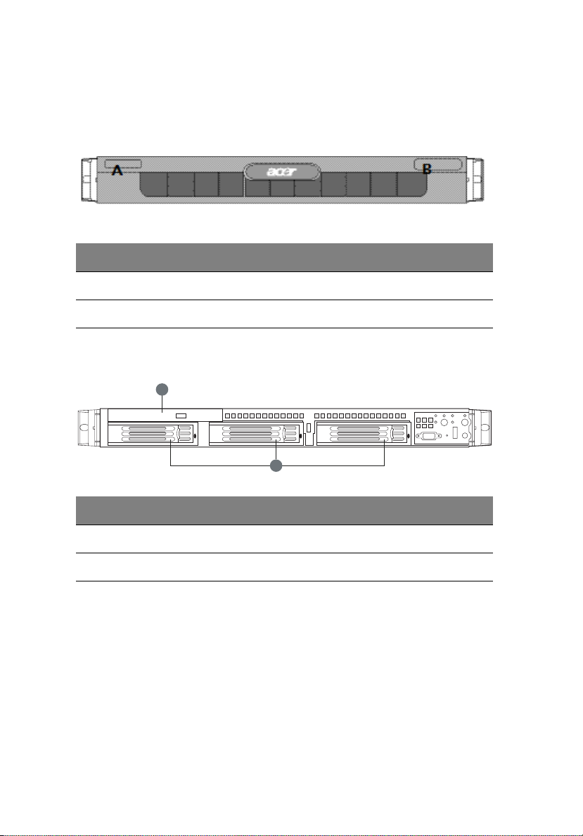
Front view (with bezel)
No. Description
A Name Plane
BLEDs
Front view (w/o bezel)
A
2 System tour
B
No. Description
A Slimline DVD/CD-RW, CD-ROM or FDD Bay
B 3.5” HDD Bay
Page 29
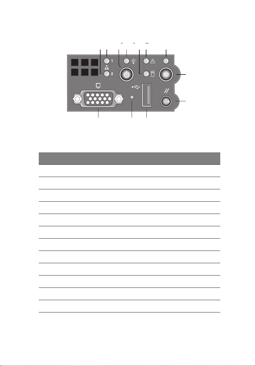
Front panel
BA F GEDC
L JK
Front Panel LED and Buttons description
Item Description
A LAN #2 Activity LED
B LAN #1 Activity LED
C Power button
17
H
I
DPower LED
E Hard Drive Activity LED
F System Status LED
G Service ID LED
H Service ID Button
I System Reset Button
JUSB connector
K Recessed NMI Button (Tool Required)
LVGA connector
Page 30

18
Control Button Functions
Item Description
2 System tour
Power/
Sleep
button
Reset
button
ID button Toggles the front panel ID LED and the baseboard ID LED on
NMI button Puts the server in a halt-state for diagnostic purposes.
Toggles the system power on/off. Sleep button for
ACPI-compatible operating systems.
Reboots and initializes the system.
and off. The baseboard LED is visible from the rear of the
chassis and allows you to locate the server from the rear of a
rack of systems.
LED Indicator Status
Item Description
NIC 1 activity
LED
NIC 2 activity
LED
Power/Sleep
LED
Continuous green light indicates a link between the system
and the network to which it is connected.
Blinking green light indicates network activity.
Continuous green light indicates the system has power
applied to it.
Blinking green indicates the system is in S1 sleep state (see
Note )
No light indicates the power is off / is in ACPI S4 or S5 state.
Hard disk
drive
status LED
System
Status LED
Random blinking green light indicates hard disk drive
activity (SATA).
No light indicates no hard disk drive activity.
Solid green indicates normal operation
Blinking green indicates degraded performance
Solid amber indicates a critical or non-recoverable condition
Blinking amber indicates a non-critical condition
No light indicates POST is running or the system is off (see
Note 1)
Page 31

Item Description
19
System
Identification
LED
Note: If the system is powered down without going through the BIOS, the
LED state that was in effect at the time of the power-down is restored when
the system is powered back on or until the BIOS clears the LED. If the system
is not powered down normally, the Power LED may blink and the System
Status LED may be off due to a failure or configuration change that
prevents the BIOS from running.
Note: After you press the Service ID button, the Service ID LED will
blink 15 times and turn off automatically. You can only turn it off
through Acer Server Management (ASM).
Solid blue indicates system identification is active
No light indicates system identification is not activated
Page 32

20
Rear view
Item Description
A PS2 Mouse Port
B Low profile PCI card bracket
C Full height PCI card bracket
D AC Power receptacle
E PS2 keyboard Ports
F RJ45 Serial B port
2 System tour
G LAN #1 Connector
H LAN #2 Connector
I Video Connector
J USB #1 Connector
K USB #2 Connector
L Power Supply Fans
Page 33

Optional Peripherals
A
B
Item Description
A Slim-line Device cage, support for FDD / DVD / CD-ROM drive
B Hard Drive Bays (3)
21
Page 34

22
9
Internal components
C
B
A
2 System tour
E
D
F
G
J
I
Item Description
A Slimline drive bay
B Backplane (optional)
C Power supply air baffle
D Power supply
E PCI add-in card riser assembly
F Server board
G Processor air duct
H Fan module
I Control panel
J Hard drive bays
H
TP012
Page 35

3 Getting Started
Page 36

This chapter gives information on setting up and
starting to use your system
Page 37

Setting up the system
Preinstallation requirements
Selecting a site
Before unpacking and installing the system, select a suitable site for
the system for maximum efficiency. Consider the following factors
when choosing a site for the system:
• Near a grounded power outlet
• Clean and dust-free
• Stable surface free from vibration
• Well-ventilated and away from sources of heat
• Secluded from electromagnetic fields produced by electrical
devices such as air conditioners, radio and TV transmitters, etc.
Checking the package contents
Check the following items from the package:
• Acer Altos R510 system
• Acer EasyBUILD
• Acer Altos R510 Accessory box
TM
25
If any of the above items are damaged or missing, contact your dealer
immediately.
Save the boxes and packing materials for future use.
Page 38

26
3 Getting Started
System startup
Turning on the system
After making sure that you have properly set up the system and
connected all the required cables, you can now power on the system.
To power on the system, press the power button on the front panel.
Refer to “Front view (w/o bezel)” on page 16, for help locating the
power button.
The system starts up and displays a welcome message. After that, a
series of power-on self-test (POST) messages appears. The POST
messages indicate if the system is running well or not.
Note: If the system does not turn on or boot after pressing the
power button, go to “Power-on problems” on page 27 for
possible causes of boot failure.
Aside from the POST messages, you can determine if the system is in
good condition by checking if the following occur during startup:
• Power indicator on the front panel lights up (green)
• Num Lock, Caps Lock, and Scroll Lock indicators on the keyboard
light up
Turning off the system
To turn off the server, on the Windows task bar click on the Start
button, point to Shut Down..., select Shut down from the drop-down
window then click on OK. You can then turn off all peripherals
connected to your server.
If you are unable to shutdown the server within Windows, press and
hold the power button for at least four seconds to force quit all
applications and shut down.
Page 39

Power-on problems
If the system does not boot after you have applied power, check the
following factors that might have caused the boot failure.
• The external power cable may be loosely connected.
Check the power cable connection from the power source to the
power cable socket on the rear panel. Make sure that the cable is
properly connected to the power source and to the power cable
socket.
• No power comes from the grounded power outlet.
Have an electrician check your power outlet.
• Loose or improperly connected internal power cables.
Check the internal cable connections. If you are not confident to
perform this step, ask a qualified technician to assist you.
Warning! Make sure all power cords are disconnected from the
electrical outlet before performing this task.
Note: If you have gone through the preceding actions and the
system still fails to boot, ask your dealer or a qualified technician
for assistance.
27
Page 40

28
3 Getting Started
Page 41

4 Configuring
the system
Page 42

This chapter discusses the precautionary
measures and installation procedures you
need to know when upgrading the system.
Page 43

31
Upgrading the system
Certain components of the Altos R510 are upgradeable such as the
drives, the CPU, the memory, and the expansion cards. However, for
safety purposes, we do not recommend that you perform these
upgrades yourself. If you want to replace or upgrade any of these
components, contact your Acer dealer or a qualified service technician
for assistance.
Important: Observe the installation precautions described in the
subsequent section when installing or removing a server
component.
Installation precautions
Before you install any server component, we recommend that you read
the following sections. These sections contain important ESD
precautions along with preinstallation and post-installation
instructions.
ESD precautions
Electrostatic discharge (ESD) can damage the processor(s),
motherboard, disk drive(s), expansion board(s), or other components.
Always observe the following precautions before you install server
components:
1 Do not remove a component from its protective packaging until
you are ready to install it.
2 Wear a wrist grounding strap and attach it to a metal part of the
server before handling components. If a wrist strap is not
available, maintain contact with the server throughout any
procedure requiring ESD protection.
Preinstallation instructions
Always observe the following before you install any component:
1 Turn off the system and all the peripherals connected to it.
2 Unplug all cables from the power outlets.
3 Open the system according to the instructions on page 35.
Page 44

32
4 Configuring the system
4 Follow the ESD precautions described in this section when
handling a server component.
5 Remove any expansion board(s) or peripheral(s) that block access
to the DIMM socket or other component connector.
See the following sections for specific installation instructions on the
component you want to install.
Warning! Failure to properly turn off the server before you start
installing components may cause serious damage. Do not attempt
the procedures described in the following sections unless you are
a qualified service technician.
Post-installation instructions
Observe the following after installing a server component:
1 See to it that all components are installed according to the
described step-by-step instructions.
2 Reinstall any expansion board(s) or peripheral(s) that you have
previously removed.
3 Reinstall the chassis panels.
4 Connect the necessary cables.
5 Turn on the system.
Page 45

33
Opening the server
Caution! Before you proceed, make sure that you have turned off
your system and all peripherals connected to it. Read the
“Preinstallation instructions” on page 31.
You need to open the Altos R510 before you can install additional
components. The top panel is removable to allow access to the system’s
internal components. Refer to the following sections for instructions.
Before opening the server
Before opening the server, observe the following precautions:
1 Turn off the system and all the peripherals connected to it.
2 Unplug all cables from the power outlets.
3 Place the system unit on a flat, stable surface.
Note: Because of the R510 design specification, the top panel
needs to be removed to access the system board.
Removing the Chassis Cover
The Altos R510 Server must be operated with the top cover in place to
ensure proper cooling. You will need to remove the top cover to add
or replace components inside of the platform. Before removing the top
cover, power down the server system and unplug all peripheral devices
and the AC power cable. None of the components inside of the
platform is hot-swappable.
1 Observe the safety and ESD precautions at the beginning of this
book.
2 Turn off all peripheral devices connected to the server. Turn off
the server.
3 Disconnect the AC power cord.
4 Remove the shipping screw (A) if it is installed.
Page 46

34
5 While holding the blue button (B) at the top of the chassis in, slide
the top cover back until it stops (C).
6 Lift the cover straight up to remove it from the platform.
4 Configuring the system
B
C
A
Page 47

35
Installing the Chassis Cover
1 Place the cover over the chassis so that the side edges of the cover
sit just inside the chassis sidewalls.
2 Slide the cover forward until it clicks into place (A).
3 (Optional) Insert the shipping screw (B) at the center of the top
cover.
4 Reconnect all peripheral devices and the AC power cord.
A
B
Page 48

36
4 Configuring the system
Removing and Installing the Front Bezel
Removing the Front Bezel
Use the steps below to remove the front bezel.
1 Pull the bezel out from the chassis.
Installing the Front Bezel
Use the steps below to install the Altos R510’s front bezel. The front
bezel is optional.
1 Push the bezel onto the front of the chassis until it clicks into
place.
Page 49

37
Removing and Installing the Processor Air Duct
Always operate your Altos R510’s chassis with the processor air duct in
place. The air duct is required for proper airflow within the chassis.
For instructions on adding or replacing a processor, first remove the
processor air duct and the processor air dam, and then see page 83 for
instructions on processor installations and removals. Return to these
instructions to reinstall the processor air dam and processor air duct
after installing your processor and heat sink.
Removing the Processor Air Duct
1 Remove the chassis cover. For instructions, see "Removing the
Chassis Cover."
2 Lift the processor air duct from its location over the two processor
sockets.
Installing the Processor Air Duct
1 If you are installing the processor air duct for the first time after
installing a second processor, break out the airflow tab over on the
side of the processor air duct that will fit over the CPU2 processor
socket.
2 Place the processor air duct over the two processor sockets,
regardless of whether one or two processors is installed. The front
edge of the air duct should contact the front fan module and the
top of the installed air duct should be flush with the top surface of
Page 50

38
the power supply. Use caution not to pinch or disengate cables
that may be near or under the air duct.
4 Configuring the system
Removing and Installing the Air Baffle
Some installation processes will require that you remove the air baffle
that is placed behind the hard drive bays, next to the fan module near
the front of your server. The steps below describe how to remove and
then install the air baffle. Use these steps only when it is indicated as
necessary for a component installation process.
Always operate your R510 chassis with the air baffle in place. The air
baffle is required for proper airflow within the chassis.
Removing the Air Baffle
1 Observe the safety and ESD precautions at the beginning of this
book. See “Safety Information.”
2 Power down the server and unplug all peripheral devices and the
AC power cable.
3 Remove the chassis cover. For instructions, see “Removing the
Chassis Cover.”
4 Note how the cables are routed over and under the air baffle. You
will need to re-route these cables.
Page 51

5 Pull up on the air baffle to remove it. See the figure below. You
may need to remove or hold cables out of the way.
TP0131
39
Page 52

40
4 Configuring the system
Installing the Air Baffle
1 Lower the baffle into the chassis between the power supply and
the drive bay area, to the left of the fan module.
2 While setting the baffle into place, route the cables beneath it
appropriately.
3 Fit the tab that extends from the front of the baffle under the
drive bay area.
4 Line up the guide pins on the baffle with the matching holes in the
chassis floor and in the backplane if you have a backplane
installed. See letter “A” in the figure below.
5 Push down firmly on the air baffle to secure it to the chassis.
Page 53

41
Installing and Removing a Hard Disk Drive
Up to three hard drives of one of the following types can be installed,
depending on the hard drive installation option used in your server
chassis and the drives supported by your server board.
1 Three fixed SATA drives or three fixed SCSI drives if the fixed drive
kit is installed.
2 Three hot-swap SATA drives if the SATA backplane is installed.
3 Three hot-swap SCSI drives if the SCSI backplane is installed.
NOTE: The Altos R510 does not support all hard drives. Contact
your local Acer dealer for details of supported hardware.
Installing a Fixed SATA Hard Disk Drive
Use these instructions only if you have installed the fixed drive kit.
CAUTION:Fixed drives are NOT hot swappable. Before removing or
replacing the drive, you must first take the server out of service,
turn off all peripheral devices connected to the system, turn off
the system by pressing the power button, and unplug the AC
power cord from the system or wall outlet.
1 Observe the safety and ESD precautions at the beginning of this
book. See “Safety Information.”
2 Power down the server and unplug all peripheral devices and the
AC power cable.
3 Remove the front bezel if it is installed. For instructions, see
“Removing and Installing the Front Bezel.”
4 Remove the chassis cover. For instructions, see “Removing the
Chassis Cover.”
5 Press the latch on the back of the fixed drive carrier and slide it out
of the bay. See letter “A” in the figure below to identify the latch
at the rear of the carrier.
Page 54

42
4 Configuring the system
6 Remove the four screws that attach the plastic retention device or
the previously installed hard drive to the drive carrier. Two screws
are at each side of the retention device or the hard drive. Store the
plastic retention device for future use.
7 With the drive circuit-side down, position the connector end of the
drive so that it is facing the back of the carrier.
8 Attach the hard drive to the carrier using the four screws removed
from the carrier.
Page 55

43
9 Insert the drive into the bay until it clicks into place.
10 If it is not already installed, connect the SATA power cable adapter
to the 3x2 power supply cable that extends from your power
supply. See letters “A” and “B” in the figure below. The power
cable adapter was provided to you with the fixed drive kit.
B
A
Page 56

44
4 Configuring the system
11 For each drive you install, route one SATA data cable from the
server board or add-in card to the hard drive, with the right-angle
end of the SATA data cable connected to the server board or addin card SATA connector. See your server board documentation or
add-in card documentation for assistance in locating the SATA
connectors on the board or add-in card.
12 See letters “C”, “D”, and “E” in the figure below and the arrow
that leads from them to the component in the chassis. This
component is the air baffle that is referred to in the following
steps. The letters “C” and “D” point to the cutouts that are
referred to in the step below. The letter “E” is the tab at the top of
the air baffle.
13 Data cables for drives installed to the right of the air baffle must
be routed through the two cutouts in the top of the air baffle
(letters “C” and “D” in the figure) and under the tab (letter “E”).
The data cable for a drive installed to the left of the air baffle must
be routed through the rear cutout of the air baffle (letter “D”)
and under the tab (letter “E”). You may need to remove the air
baffle to route the cables underneath it. To see how to remove
and then install the air baffle, see “Removing and Installing the Air
Baffle. “
14 Connect the loose end of the data cable to the rear of the SATA
drive. See letter “A” in the figure to identify the location of the
connector at the rear of the SATA drive.
Page 57

A
B
E
D
C
A
15 See letter “B” in the figure below and the arrow that leads from
this letter to the component in the chassis. This component is the
air baffle that is referred to in the following steps. The letter “B”
points to the cutout that is referred to.
16 Power cables for drives installed to the right side of the air baffle
must be routed beneath the front cutout in the underside of the
air baffle. The power cable for a drive installed to the left of the
air baffle does not need to be routed under the air baffle. See
letter “B” in the figure below to identify the air baffle and the
cutout area. You may need to remove the air baffle to route cables
underneath it. To see how to remove and then install the air
baffle, see “Removing and Installing the Air Baffle. “
17 Connect the SATA power cable adapter end(s) to the rear of the
SATA drive. See letter “A” in the figure below to locate the
connector on the SATA drive.
45
Page 58

46
4 Configuring the system
A
B
A
18 (Optional) Install the front bezel. For instructions, see “Removing
and Installing the Front Bezel.”
19 Install the chassis cover. For instructions, see “Installing the Chassis
Cover.”
20 Plug all peripheral devices and the AC power cable back into the
server.
Removing a Fixed SATA Hard Disk Drive
CAUTION: Fixed drives are NOT hot swappable. Before removing
or replacing the drive, you must first take the server out of service,
turn off all peripheral devices connected to the system, turn off
the system by pressing the power button, and unplug the AC
power cord from the system or wall outlet.
Page 59

47
1 Observe the safety and ESD precautions at the beginning of this
book. See “Safety Information.”
2 Power down the server and unplug all peripheral devices and the
AC power cable.
3 Remove the chassis cover. For instructions, see “Removing the
Chassis Cover.”
4 Remove the front bezel if it is installed. For instructions, see
“Removing and Installing the Front Bezel.”
5 Disconnect the SATA data connector and power cables from the
rear of the SATA drive.
6 Press the latch on the back of the fixed drive carrier and slide it out
of the bay.
7 Remove the four screws that attach the hard drive to the drive
carrier. Lift the drive from the carrier. Store the drive in an antistatic bag.
8 If you are not installing a new drive, place the plastic retention
device into the drive carrier, using the four screws you removed
from the hard drive.
9 Insert the screws that held the drive in the carrier into the screw
locations on the carrier for future use.
10 Slide the drive carrier back into the chassis until it clicks into place.
NOTE:For proper airflow, the hard drive carrier must be replaced
in the chassis, even if no hard drive is installed in it.
11 (Optional) Install the front bezel. For instructions, see “Removing
and Installing the Front Bezel.”
12 Install the chassis cover. For instructions, see “Removing the
Chassis Cover.”
13 Plug all peripheral devices and the AC power cable back into the
server.
Page 60

48
4 Configuring the system
Installing a SATA or SCSI Hot-swap Hard Disk Drive
Use these instructions only if you have installed the SATA or SCSI
backplane kit. Please refer to Page 79 for details of how to install the
backplane.
1 Remove the front bezel if it is installed. For instructions, see
“Removing and Installing the Front Bezel.”
2 Press in on the green latch at the front of the hard drive carrier.
See letter “A” in the figure below.
3 Pull out on the black lever and slide the carrier from the chassis.
See letter “B” in the figure below.
B
A
4 Remove the four screws that attach the plastic retention device or
the previously installed hard drive to the drive carrier. Two screws
are at each side of the retention device or the hard drive. Store the
plastic retention device for future use.
Page 61

49
A
5 Remove the hard drive from its wrapper and place it on an
antistatic surface.
6 Set any jumpers and/or switches on the drive according to the
drive manufacturer’s instructions.
7 With the drive circuit-side down, position the connector end of the
drive so that it is facing the rear of the drive carrier.
Page 62

50
8 Align the holes in the drive to the holes in the drive carrier and
attach it to the carrier with the screws that were attached to the
plastic retention device.
9 With the black lever in the fully open position, slide the drive
assembly into the chassis. The green latch at the front of the drive
carrier must be to the right. Do not push on the black drive carrier
lever until the lever begins to close by itself.
10 When the black drive carrier lever begins to close by itself, push on
it to lock the drive assembly into place.
11 (Optional) Install the front bezel.
4 Configuring the system
A
B
Removing a SATA or SCSI Hot-swap Hard Disk Drive
Use these instructions only if you have installed the SATA or SCSI
backplane kit.
Page 63

1 Remove the front bezel if it is installed. For instructions, see
“Removing and Installing the Front Bezel.”
2 Press in on the green latch at the front of the hard drive carrier.
3 Pull out on the black lever to slide the carrier from the chassis.
4 Remove the four screws that attach the hard drive to the drive
carrier. Lift the drive from the carrier. Store the drive in an antistatic bag.
5 If you are not installing a new drive, place the plastic retention
device into the drive carrier, using the four screws you removed
from the hard drive.
6 Insert the screws that held the drive in the carrier into the screw
locations on the carrier for future use.
7 With the black lever in the fully open position, slide the drive
carrier into the chassis. The green latch must be to the right. Do
not push on the black lever until the lever begins to close by itself.
NOTE:For proper airflow, the hard drive carrier must be replaced
in the chassis, even if no hard drive is installed in it.
51
8 When the black lever begins to close by itself, push on it to lock
the drive carrier into place.
9 (Optional) Install the front bezel. For instructions, see “Removing
and Installing the Front Bezel.”
Page 64

52
4 Configuring the system
Installing or Removing a Floppy Drive
Floppy drives are installed in different ways, depending on the
following items:
1 The SATA or SCSI backplane is installed and you want to install the
floppy drive into the slimline drive bay.
2 No backplane is installed and you want to install the floppy drive
into the slimline drive bay.
3 The SATA or SCSI backplane is installed and you have installed a
CD-ROM or DVD/CD-RW drive into the slimline drive bay. You
want to install the floppy drive into a bay that was intended for a
hard drive (optional conversion kit is required).
Look carefully at the heading titles below before beginning your
installation to be sure you are following the correct instructions for
your system.
CAUTION:Floppy drives are NOT hot swappable. Before removing
or replacing the drive, you must first take the server out of service,
turn off all peripheral devices connected to the system, turn off
the system by pressing the power button, and unplug the AC
power cord from the system or wall outlet.
Installing a Floppy Drive into Slimline Bay (Backplane Installed)
Use these instructions if you are installing a floppy drive into the Altos
R510’s slimline drive bay at the upper left side of your chassis and your
system includes either the SATA or SCSI backplane. You will know if
you have one of these backplanes installed if you can install either hotswap SATA or hot-swap SCSI drives.
NOTE: The carrier for the slimline floppy drive that is used in these
instructions was sent to you in the hardware kit that came with
your system.
1 Observe the safety and ESD precautions at the beginning of this
book. See “Safety Information.”
Page 65

2 Power down the server and unplug all peripheral devices and the
AC power cable.
3 Remove the chassis cover. For instructions, see “Removing the
Chassis Cover.”
4 Remove the front bezel if it is installed. For instructions, see
“Removing and Installing the Front Bezel.”
5 Align the two holes at the left side of the floppy drive with the
two cutouts in the floppy drive carrier. See letter “A” in the figure
below.
6 Lower the right side of the floppy drive into the carrier until it
clicks into place. See letter “B” in the figure below.
A
53
B
7 Open the connector on the rear of the floppy drive by pulling up
on the connector cover. See letter “A” in the figure below.
8 Insert one end of the 26-pin floppy drive flat flex cable end into
the connector. See letter “B” in the figure below.
9 Push down on the connector cover to lock the cable into place. See
letter “C” in the figure below.
Page 66

54
4 Configuring the system
10 Slide the floppy drive assembly into the slimeline bay of the chassis
until it clicks into place. See letter “A” in the figure below.
11 Open the connector labeled “Floppy Con” on the backplane by
pulling up on the connector cover. See letter “B” in the figure
below.
12 Insert the loose end of the floppy cable into the backplane
connector. See letter “C” in the figure below.
13 Push in on the connector cover to lock the cable into place. See
letter “D” in the figure below.
14 Install the chassis cover. For instructions, see “Installing the Chassis
Cover.”
15 (Optional) Install the front bezel. For instructions, see “Removing
and Installing the Front Bezel.”
16 Plug all peripheral devices and the AC power cable back into the
server.
Page 67

55
Removing a Floppy Drive from the Slimline Bay (Backplane Installed)
1 Observe the safety and ESD precautions at the beginning of this
book. See “Safety Information.”
2 Power down the server and unplug all peripheral devices and the
AC power cable.
3 Remove the chassis cover. For instructions, see “Removing the
Chassis Cover.”
4 Remove the front bezel if it is installed. For instructions, see
“Removing and Installing the Front Bezel.”
5 Pull up at the top of the connector on the backplane labeled
“Floppy Con” to release the flat flex cable from it.
6 Push in on the blue lever at the rear of the drive carrier.
7 Slide the floppy drive carrier out through the front of the chassis.
8 Remove the flat flex cable from the rear of the floppy.
9 Press downward on the side of the carrier to release the drive from
the drive carrier.
10 Store the floppy drive carrier and the flat flex cable for future use.
11 Install the slimline filler panel into slimline bay if no drive is to be
installed into the bay.
12 Install the chassis cover. For instructions, see “Installing the Chassis
Cover.”
13 (Optional) Install the front bezel. For instructions, see “Removing
and Installing the Front Bezel.”
14 Plug all peripheral devices and the AC power cable back into the
server.
Installing a Floppy Drive into Slimline Bay (No Backplane Installed)
NOTE: The carrier for the slimline floppy drive that is used in these
instructions was sent to you in the hardware kit that came with
your Altos R510 Server Chassis. The interposer board and floppy
Page 68

56
drive power adapter cable used in these instructions was sent to
you with your fixed drive kit.
4 Configuring the system
1 Observe the safety and ESD precautions at the beginning of this
book. See “Safety Information.”
2 Power down the server and unplug all peripheral devices and the
AC power cable.
3 Remove the chassis cover. For instructions, see “Removing the
Chassis Cover.”
4 Remove the front bezel if it is installed. For instructions, see
“Removing and Installing the Front Bezel.”
5 Align the two holes at the left side of the floppy drive with the
two cutouts in the floppy drive carrier. See letter “A” in the figure
below.
6 Lower the right side of the floppy drive into the carrier until it
clicks into place. See letter “B” in the figure below.
A
B
7 Open the connector on the rear of the floppy drive by pulling up
on the connector cover. See letter “A” in the figure below.
8 Insert one end of the 26-pin flat flex cable end into the connector.
See letter “B” in the figure below.
Page 69

57
9 Push down on the connector cover to lock the cable into place. See
letter “C” in the figure below.
10 Open the connector on the interposer board by pulling out on the
connector cover. See letter “D” in the figure below.
11 Insert the loose end of the floppy cable into the interpose board
connector. See letter “E” in the figure below.
12 Push in on the connector cover to lock the cable into place. See
letter “F” in the figure below.
13 Lower the interposer board into the floppy drive tray at the rear of
the floppy drive and engage the notch on the board. See Letter
“A” in the figure below.
14 Attach the interposer board to floppy drive with the screw that
was included with the interposer board. See letter “B” in the
figure below. In the diagram, the flat flex cable been removed for
clarity.
Page 70

58
4 Configuring the system
A
B
15 Slide the floppy drive assembly into the chassis until it clicks into
place. See letter “A” in the figure below.
16 Connect the 2x2 end of the floppy drive power cable that was
included with your kit to the 2x2 power connector on the SATA
power adapter cable. See letters “B” and “C” in the figure below.
17 Connect the remaining end of the floppy drive power cable to the
power connector on the rear of the floppy drive. See letter “D” in
the figure.
18 Connect the floppy drive data cable that was included with your
kit between the floppy drive data connector and the server board.
See letters “E” and “F” in the figure. See your server board
documentation for assistance in locating the connector location on
the server board.
19 Route the floppy drive data cable over the air baffle, as shown in
the diagram below.
Page 71

20
59
F
A
C
B
E
E
D
D
F
B
C
TP01174
21 Install the chassis cover. For instructions, see “Installing the Chassis
Cover.”
22 (Optional) Install the front bezel. For instructions, see “Removing
and Installing the Front Bezel.”
23 Plug all peripheral devices and the AC power cable back into the
server.
Page 72

60
4 Configuring the system
Removing a Floppy Drive from the Slimline Bay (No Backplane Installed)
1 Observe the safety and ESD precautions at the beginning of this
book. See “Safety Information.”
2 Power down the server and unplug all peripheral devices and the
AC power cable.
3 Remove the chassis cover. For instructions, see “Removing the
Chassis Cover.”
4 Remove the front bezel if it is installed. For instructions, see
“Removing and Installing the Front Bezel.”
5 Detach the power and data cables from the rear of the floppy
drive.
6 Detach the data cable from the server board and remove the cable
from the chassis.
7 Push in on the blue lever at the rear of the drive carrier.
8 Slide the floppy drive carrier out through the front of the chassis.
9 Remove the screw that attaches the interposer board to the drive.
Lift the interposer board from the drive.
10 Remove the flat flex cable from the floppy drive and from the
interposer board.
11 Press downward on the side of the carrier to release the drive from
the drive carrier.
12 Store the floppy drive carrier, the interposer board, the flat flex
cable, and the floppy drive data cable for future use.
13 Install the slimline filler panel into slimline bay if no drive is to be
installed into the bay.
14 Install the chassis cover. For instructions, see “Installing the Chassis
Cover.”
15 (Optional) Install the front bezel. For instructions, see “Removing
and Installing the Front Bezel.”
16 Plug all peripheral devices and the AC power cable back into the
server.
Page 73

61
Installing a Floppy Drive into the Converted Hard Drive Bay (Backplane Installed)
The slimline floppy drive conversion kit can only be installed into a
system that is using either the SATA or the SCSI backplane. You will
know if you have one of these backplanes installed if you can install
either hot-swap SATA or hot-swap SCSI drives. The conversion kit must
be installed in the left hard drive bay.
1 Observe the safety and ESD precautions at the beginning of this
book. See “Safety Information.”
2 Power down the server and unplug all peripheral devices and the
AC power cable.
3 Remove the chassis cover. For instructions, see “Removing the
Chassis Cover.”
4 Remove the front bezel if it is installed. For instructions, see
“Removing and Installing the Front Bezel.”
5 Remove the left hot-swap hard drive carrier from the chassis.
6 Remove the screws that attach the slide rails to the floppy drive
conversion kit carrier.
7 Slide the floppy drive into the drive carrier, rear of the drive first,
with the underside of the drive facing down.
8 Line up the holes in the side of the drive with the holes in the
carrier. See letter “A” in the figure below.
Page 74

62
4 Configuring the system
A
A
9 Attach the floppy drive to the carrier with the screws that came
with your floppy drive conversion kit. One screw attaches at each
side.
10 Reattach the slide rails onto the floppy drive conversion kit carrier.
Page 75

63
11 Open the connector on the rear of the floppy drive by pulling up
on the connector cover.
12 Insert one end of the flat flex cable end into the floppy drive
connector.
13 Push down on the connector cover to lock the cable into place.
14 Slide the carrier assembly into the left hard drive bay until it clicks
into place. See letter “A” in the figure below.
15 Open the connector labeled “Floppy Con” on the backplane by
pulling up on the connector cover. See letter “B” in the figure
below.
16 Insert the loose end of the flat flex cable into the backplane
connector. See letter “C” in the figure below.
17 Push in on the connector cover to lock the cable into place. See
letter “D” in the figure below.
Page 76

64
18 Install the chassis cover. For instructions, see “Installing the Chassis
Cover”
19 (Optional) Install the front bezel. For instructions, see “Removing
and Installing the Front Bezel.”
20 Plug all peripheral devices and the AC power cable back into the
server.
4 Configuring the system
Removing a Floppy Drive from the Converted Hard Drive Bay
1 Observe the safety and ESD precautions at the start of this book.
2 Power down the server and unplug all peripheral devices and the
AC power cable.
3 Remove the chassis cover. For instructions, see “Removing the
Chassis Cover.”
4 Remove the front bezel if it is installed. For instructions, see
“Removing and Installing the Front Bezel.”
Page 77

65
5 Open the connector labeled “Floppy Con” on the backplane by
pulling up on the connector cover. Remove the flat flex cable from
the backplane.
6 Push in on the lever at the rear of the floppy carrier and slide the
drive from the front of the chassis.
7 Open the connector cover on the rear of the floppy drive by
pulling up on it. Release the flat flex cable from the drive.
8 Remove the two screws at each side that hold the drive rails to the
drive carrier. Lift the two rails from the carrier.
9 Disconnect the two screws attaching the drive to the converted
hard drive bay carrier.
10 Install an empty hot-swap hard drive carrier into chassis drive bay
if no floppy or hard drive is to be installed into the bay.
11 Store the screws, the converted drive bay carrier, the side rails, and
the flat flex cable for future use.
12 Install the chassis cover. For instructions, see
13 (Optional) Install the front bezel.
14 Plug all peripheral devices and the AC power cable back into the
server.
Page 78

66
4 Configuring the system
Installing or Removing a DVD/CD-RW or CD-ROM Drive
CAUTION: DVD/CD-RW and CD-ROM drives are NOT hot
swappable. Before removing or replacing the drive, you must first
take the server out of service, turn off all peripheral devices
connected to the system, turn off the system by pressing the
power button, and unplug the AC power cord from the
system or wall outlet.
Installing a DVD/CD-RW or CD-ROM Drive into Slimline Bay (Backplane Installed)
NOTE: The carrier for the slimline DVD/CD-RW drive / CD-ROM
drive was pre-installed in the slimline drive bay of your Altos R510
Server Chassis.
1 Observe the safety and ESD precautions at the beginning of this
book. See “Safety Information.”
2 Power down the server and unplug all peripheral devices and the
AC power cable.
3 Remove the chassis cover. For instructions, see “Removing the
Chassis Cover.”
4 Remove the front bezel if it is installed. For instructions, see
“Removing and Installing the Front Bezel.”
5 Push in on the blue lever at the rear of the DVD/CD-RW or CD-ROM
drive carrier and push the carrier out through the front of the
chassis.
6 Align the two holes at left edge of DVD/CD-RW or CD-ROM drive
with the cutouts in drive carrier. See letter “A” in the figure
below.
7 Lower the right side of the DVD/CD-RW or CD-ROM drive into the
carrier until it clicks into place. See letter “B” in the figure below.
Page 79

67
8 Use the two screws indicated in the figure to attach the interposer
board to the DVD/CD-RW or CD-ROM drive. See letters “C” and
“D” in the figure.
9 Attach the 44-pin CD-ROM drive cable to the exposed side / back
of the interposer board. See letter “E” in the figure.
10 Slide the DVD/CD-RW or CD-ROM drive carrier into the chassis. See
letter “A” in the figure below.
11 Connect the loose end of the CD-ROM drive cable to the backplane
connector. See letter “B” in the figure.
Page 80

68
A
12 Install the chassis cover. For instructions, see “Installing the Chassis
Cover.”
13 (Optional) Install the front bezel. For instructions, see “Removing
and Installing the Front Bezel.”
14 Plug all peripheral devices and the AC power cable back into the
server.
4 Configuring the system
B
Removing a DVD/CD-RW or CD-ROM Drive from the Slimline Bay (Backplane Installed)
1 Observe the safety and ESD precautions at the beginning of this
book. See “Safety Information.”
2 Power down the server and unplug all peripheral devices and the
AC power cable.
3 Remove the chassis cover. For instructions, see “Removing the
Chassis Cover.”
4 Remove the front bezel if it is installed.
5 Disconnect the CD-ROM data cable from the backplane.
6 Push in on the blue lever at the rear of the drive carrier. Slide the
drive carrier out through the front of the chassis.
7 Press downward on the side of the carrier release the drive from
the drive carrier.
Page 81

69
8 Disconnect the data cable from the rear of the DVD/CD-RW or CD-
ROM drive.
9 Remove the two screws at the rear of the DVD/CD-RW or CD-ROM
drive to disconnect the interposer board.
10 Store the screw and interposer board for future use. Suggestion:
tape the screw to the drive carrier.
11 Slide the empty drive carrier into the chassis until it clicks into
place.
12 Install the chassis cover. For instructions, see “Installing the Chassis
Cover.”
13 (Optional) Install the front bezel. For instructions, see “Removing
and Installing the Front Bezel.”
14 Plug all peripheral devices and the AC power cable back into the
server.
Installing DVD/CD-RW or CD-ROM Drive into Slimline Bay (No Backplane Installed)
NOTE: The carrier for the slimline DVD/CD-RW drive / CD-ROM
drive was pre-installed in the slimline drive bay of your Altos R510
Server Chassis. The interposer board and floppy drive power
adapter cable used in these instructions was sent to you with your
fixed drive kit.
1 Observe the safety and ESD precautions at the beginning of this
book. See “Safety Information.”
2 Power down the server and unplug all peripheral devices and the
AC power cable.
3 Remove the chassis cover. For instructions, see “Removing the
Chassis Cover.”
4 Remove the front bezel if it is installed. For instructions, see
“Removing and Installing the Front Bezel.”
5 Push in on the blue lever at the rear of the DVD/CD-RW or CD-ROM
drive carrier and push the carrier out through the front of the
chassis.
Page 82

70
4 Configuring the system
6 Align the two holes at left edge of DVD/CD-RW or CD-ROM drive
with the cutouts in drive carrier. See letter “A” in the figure
below.
7 Lower the right side of the DVD/CD-RW or CD-ROM drive into the
carrier until it clicks into place. See letter “B” in the figure below.
8 Use the two screws indicated in the figure to attach the interpose
board to the DVD/CD-RW or CD-ROM drive. See letters “C” and
“D” in the figure.
9 Insert the DVD/CD-RW or CD-ROM drive carrier into the chassis.
See letter “A” in the figure below.
10 If it is not already connected, connect the 2x3 end of the DVD/CD-
RW or CD-ROM drive power cable that was included with your
fixed drive kit to the 2x3 power connector on the SATA power
adapter cable. See letters “B” and “C” in the figure below.
11 Connect the drive power cable to the power connector on the rear
of the DVD/CD-RW or CD-ROM drive. See letter “D” in the figure.
12 Connect the DVD/CD-RW or CD-ROM drive data cable that was
included with your kit between the interposer board and the IDE
connector on the server board. See letters “E” and “F” in the
figure below. See your server board documentation for assistance
in locating the connector location on the server board.
13 Route the DVD/CD-RW or CD-ROM drive data cable over the top of
air baffle, as shown in the diagram below.
Page 83

71
14 Install the chassis cover. For instructions, see “Installing the Chassis
Cover.”
15 (Optional) Install the front bezel. For instructions, see “Removing
and Installing the Front Bezel.”
16 Plug all peripheral devices and the AC power cable back into the
server.
F
C
B
E
D
F
B
C
E
D
A
Page 84

72
4 Configuring the system
Installing and Removing a PCI Riser Connector
CAUTION: PCI riser connectors are NOT hot swappable. Before
removing or replacing the riser connector, you must first take the
server out of service, turn off all peripheral devices connected to
the system, turn off the system by pressing the power button, and
unplug the AC power cord from the system or wall outlet.
Installing a PCI Riser Connector
To install the PCI riser connector, use the following instructions.
1 Observe the safety and ESD precautions at the beginning of this
book. See “Safety Information.”
2 Power down the server and unplug all peripheral devices and the
AC power cable.
3 Remove the chassis cover. For instructions, see “Removing the
Chassis Cover.”
4 Pull up on the two latches on the assembly. See letter “A” in the
figure below.
5 Lift the PCI riser assembly from the chassis.
Page 85

73
6 Line up the screws on the riser assembly with the slot and the large
hole on the riser connector.
7 Press and hold the blue riser locking lever. See letter “A” in the
figure below.
8 Place riser connector onto the retention pins.
9 Slide the riser connector to the right to lock it into place.
10 Release the blue locking lever.
11 Install a PCI add-in card, if desired. For instructions, see “Installing
a PCI Add-in Card.”
12 Position the riser assembly over the PCI sockets on the server board
(see letter “A” in the figure below), lining up the four hooks at the
rear of the riser assembly (see letter “B”) with the four slots in the
rear of the chassis (see letter “C”).
13 Push the riser assembly down until the assembly is securely seated.
Page 86

74
14 Install the chassis cover. For instructions, see “Installing the Chassis
Cover.”
15 Plug all peripheral devices and the AC power cable back into the
server.
4 Configuring the system
Removing a PCI Riser Connector
The PCI riser connector can be replaced if it fails or if a different option
is required. To replace the PCI riser connector, use the following
instructions to remove it, and then follow the instructions under
“Installing a PCI Riser Connector” to install a new riser connector.
NOTE: To eliminate the possibility of installing the replacement
connector on the wrong side of the PCI riser assembly, replace one
connector at a time.
1 Observe the safety and ESD precautions at the beginning of this
book. See “Safety Information.”
2 Power down the server and unplug all peripheral devices and the
AC power cable.
3 Remove the chassis cover. For instructions, see “Removing the
Chassis Cover.”
Page 87

75
4 Lift up on the two blue levers to lift the PCI riser assembly from the
chassis.
5 Remove any PCI add-in cards that are installed in the connector.
For instructions, see “Removing a PCI Add-in Card.”
6 Push back on the blue release lever at the end of the riser
connector. While holding the lever back, push firmly on the other
edge of the board to disengage the board from the riser.
7 Follow the steps under “Installing a PCI Riser Connector” to install
a replacement riser connector.
8 Install the chassis cover. For instructions, see “Installing the Chassis
Cover.”
Page 88

76
4 Configuring the system
Installing and Removing a PCI Add-in Card
Installing a PCI Add-in Card
In the slots provided by the PCI riser connector, you can install either
one or two add-in cards. Use the following instructions to install an
add-in card.
1 Observe the safety and ESD precautions at the beginning of this
book. See “Safety Information.”
2 Power down the server and unplug all peripheral devices and the
AC power cable.
3 Remove the chassis cover. For instructions, see “Removing the
Chassis Cover.”
4 Pull up on the two latches on the assembly. See letter “A” in the
figure below.
5 Lift the PCI riser assembly from the chassis.
6 Open the PCI retention clip on the PCI riser card assembly. See
letter “A” in the figure below.
7 Remove the filler panel at the back of the riser assembly. See letter
“B” in the figure below.
Page 89

77
8 Insert the add-in card until it seats in riser card connector. Make
sure the bracket inserts into the matching slot. See letter “C”.
9 Close the retention clip. See letter “A” in the figure.
A
B
C
10 Position the riser assembly over the PCI sockets on the server board
(see letter “A” in the figure below), lining up the four hooks at the
rear of the riser assembly (see letter “B”) with the four slots in the
rear of the chassis (see letter “C”).
11 Push the riser assembly down until the assembly is securely seated
(as shown in the diagram on page 74).
12 Install the chassis cover. For instructions, see “Installing the Chassis
Cover.”
13 Plug all peripheral devices and the AC power cable back into the
server.
Removing a PCI Add-in Card
1 Observe the safety and ESD precautions at the beginning of this
book. See “Safety Information.”
2 Power down the server and unplug all peripheral devices and the
AC power cable.
3 Remove the chassis cover. For instructions, see “Removing the
Chassis Cover.”
4 Pull up on the two latches on the riser assembly.
5 Lift the PCI riser assembly from the chassis.
6 Open the PCI retention clip on the PCI riser card assembly.
Page 90

78
4 Configuring the system
7 Remove the add-in card
8 Close the retention clip.
9 Position the riser assembly over the PCI sockets on the server
board.
10 Push the riser assembly down until the assembly is securely seated.
11 Install the chassis cover. For instructions, see “Installing the Chassis
Cover.”
12 Plug all peripheral devices and the AC power cable back into the
server.
Page 91

79
Installing and Removing the SATA or SCSI Backplane (Optional)
You received your server chassis with your choice of one of drive
installation options:
• A hot-swap SCSI option that came with a SCSI backplane board.
• A hot-swap SATA option that came with a SATA backplane board.
• A fixed SATA drive option. This option does not include a board to
install.
CAUTION: The backplane is NOT hot swappable. Before removing
or replacing the backplane, you must first take the server out of
service, turn off all peripheral devices connected to the system,
turn off the system by pressing the power button, and unplug the
AC power cord from the system or wall outlet.
The backplane board and the hardware that came with the backplane
can be replaced if your backplane fails or if a different option is
required. To replace the backplane, use the following instructions to
remove and then to install a backplane.
Removing the SATA or SCSI Backplane
1 Observe the safety and ESD precautions at the beginning of this
book. See “Safety Information.”
2 Power down the server and unplug all peripheral devices and the
AC power cable.
3 Remove the chassis cover. For instructions, see “Removing the
Chassis Cover.”
4 Remove the air baffle. For instructions, see “Removing the Air
Baffle.”
5 Remove all hot-swap drive carriers. For instructions, see
“Removing a SATA or SCSI Hot-swap Hard Disk Drive.”
6 Disconnect all cables from the backplane:
7 Loosen the blue captive screw at the right side of the backplane.
See letter “A” in the figure below
Page 92

80
8 Slide the board to the right until it stops. Do not pull on any
components on the board – grasp only on the edges of the board.
See letter “B” in the figure.
9 Lift the backplane from the chassis. The holes in the backplane will
slide from the matching pins in the chassis. If any of the pins
catches on the holes, it means you have not slid the board fully to
the right. See letter “C” in the figure.
C
4 Configuring the system
A
B
Installing the SCSI or SATA Backplane
1 Observe the safety and ESD precautions at the beginning of this
book. See “Safety Information.”
2 Power down the server and unplug all peripheral devices and the
AC power cable.
3 Remove the chassis cover. For instructions, see “Removing the
Chassis Cover.”
4 Remove the air baffle. For instructions, see “Removing the Air
Baffle.”
Page 93

81
5 Remove all hot-swap drive carriers. For instructions, see
“Removing a SATA or SCSI Hot-swap Hard Disk Drive.”
6 Set the backplane board in place so that the holes in the board fit
through the pegs in the bottom of the server chassis. See letter
“A” in the figure below.
7 Slide the board to the left until it stops. Do not pull on any
components on the board – grasp only on the edges of the board.
See letter “B” in the figure.
8 Tighten the blue captive screw at the right side of the backplane
board. See letter “C” in the figure.
C
A
B
9 Connect the following cables to the backplane:
• Front panel cable
• Power cable
• Flex cable. The cable indicates the end that is to be connected
to the backplane.
• (SCSI backplane only): SCSI Channel A cable. The cable
indicates the end that is to be connected to the backplane.
• (SATA backplane only): SATA cable(s).
Page 94

82
4 Configuring the system
• Floppy drive cable, if applicable
• CD-ROM drive cable, if applicable
10 Install the air baffle. For instructions, see “Installing the Air
Baffle.”
11 Install the chassis cover. For instructions, see “Installing the Chassis
Cover.”
12 Install the hot-swap hard drive(s), if applicable. For instructions,
see “Installing a SATA or SCSI Hot-swap Hard Disk Drive.”
13 (Optional) Install the front bezel. For instructions, see “Installing
the Front Bezel.”
Page 95

Processor Installation and Upgrade
Installing or Replacing the Processor
CAUTION
Processor must be appropriate: You may damage the server
board if you install a processor that is inappropriate for your
server. Contact your local Acer dealer for a list of compatible
processor(s).
ESD and handling processors: Reduce the risk of electrostatic
discharge (ESD) damage to the processor by doing the following:
(1) Touch the metal chassis before touching the processor or server
board. Keep part of your body in contact with the metal chassis to
dissipate the static charge while handling the processor. (2) Avoid
moving around unnecessarily.
Installing the Processor
83
To install a processor, follow these instructions:
1 Observe the safety and ESD precautions at the beginning of this
book.
2 Turn off all peripheral devices connected to the server. Turn off
the server.
3 Disconnect the AC power cord from the server.
4 Remove the server’s cover. See the documentation that
accompanied your server chassis for instructions on removing the
server’s cover
5 Locate the processor socket and raise the socket handle
completely.
6 Align the pins of the processor with the socket, and insert the
processor into the socket.
Page 96

84
A
B
A
NOTE: Make sure the alignment triangle mark and the alignment
triangle cutout align correctly.
7 Lower the socket lever completely.
4 Configuring the system
Page 97

85
Installing the Heat Sink(s)
1 The heat sink has Thermal Interface Material (TIM) located on the
bottom of it. Use caution when you unpack the heat sink so you do
not damage the TIM.
2 Set the heat sink over the processor, lining up the four captive
screws with the four posts surrounding the processor.
3 Loosely screw in the captive screws on the heat sink corners in a
diagonal manner (screw in one screw, then the screw located
diagonally to the first screw). Do not fully tighten one screw
before tightening another.
4 Gradually and equally tighten each captive screw until each is
firmly tightened. Do not over-tighten the screws.
5 Reinstall and reconnect any parts you removed or disconnected to
reach the processor sockets.
6 Replace the server’s cover and reconnect the AC power cord. See
the documentation that accompanied your server chassis for
instructions on installing the server’s cover.
Page 98

86
4 Configuring the system
Removing a Processor
1 Observe the safety and ESD precautions at the beginning of this
book.
2 Turn off all peripheral devices connected to the server. Turn off
the server.
3 Remove the AC power cord from the server.
4 Remove the server’s cover. See the documentation that
accompanied your server chassis for instructions on removing the
server’s cover.
5 Unplug the processor fan cable from the server board.
6 Loosen the four captive screws on the corners of the heat sink.
7 Twist the heat sink slightly to break the seal between the heat sink
and the processor.
8 Lift the heat sink from the processor. If it does not pull up easily,
twist the heat sink again. Do not force the heat sink from the
processor. Doing so could damage the processor.
9 Lift the processor lever.
10 Remove the processor.
If installing a replacement processor, see “Installing the Processor.”
Otherwise, reinstall the chassis cover.
Page 99

Memory Installations and Upgrade
Upgrading the system memory
This section includes instructions for removing and installing a
memory module.
The Altos R510 provides six DDR2 400 DIMM sites in two DIMM
channels. DIMMs 1A, 2A and 3A are connected to memory channel A.
DIMM 1B, 2B and 3B are connected to memory channel B.
The maximum memory capacity is 12GB DDR - 2 400 memory.
Memory DIMM technologies supported are: 512MB, 1 GB and 2 GB.
Mem-
DIMM 1BDIMM 1ADIMM 2BDIMM 2ADIMM 3ADIMM
3B
512MB 1-way
ory
Interleave
87
1GB 1-way
2GB 1-way
512MB 512MB 2-way
1GB 1GB 2-way
2GB 2GB 2-way
512MB 512MB 512MB 512MB 2-way
1GB 1GB 1GB 1GB 2-way
2GB 2GB 2GB 2GB 2-way
512MB 512MB 512MB 512MB 512MB 512MB 2-way
1GB 1GB 1GB 1GB 1GB 1GB 2-way
2GB 2GB 2GB 2GB 2GB 2GB 2-way
Page 100

88
4 Configuring the system
The minimum memory configuration is one DIMM, installed in DIMM
socket 1B (the socket farthest from the processors). However, for
optimum performance and dual-channel interleave operation, a
minimum of two DIMMs should be installed. DIMMs on channel A are
paired with DIMMs on channel B to configure 2-way interleaving.
Both DIMM1B and DIMM1A must be populated before any DIMMs are
installed. DIMM2B and DIMM2A must be populated in pairs. DIMM3B
and DIMM3A must be populated in pairs.
Both DIMMs in a bank must be identical (same manufacturer, CAS
latency, number of rows, columns and devices, timing parameters etc.).
Although DIMMs within a bank must be identical, the BIOS supports
various DIMM sizes and configurations allowing the banks of memory
to be different.
Note: Dual-channel memory requires symmetrical memory
modules using the same density (e.g. 512MB), bus width (e.g. x8
,x16) and granule technology (e.g. 256M-bit, 512M-bit)
 Loading...