

Page 1
Service guide files and updates are available
please refer to http://csd.acer.com.tw
Ducati Service Guide
on the ACER/CSD web; for more information,
I / 66
Page 2

Copyright
Copyright © 2012 by Acer Incorporated. All rights reserved. No part of this publication may be reproduced, transmitted, transcribed, stored in
a retrieval system or translated into any language or computer language, in any form or by any means, electronic, mechanical, magnetic,
optical, chemical, manual or otherwise, without the prior written permission of Acer Incorporated.
Disclaimer
The information in this guide is subject to change without notice.
Acer Incorporated makes no representations or warranties, either expressed of implied, with respect to the contents hereof and specially
disclaims any warranties of merchantability or fitness for any particular purpose. Any Acer Incorporated software described in this manual is
sold or licensed “ as is”. Should the program prove detective following their purchase, the buyer (are not Acer Incorporated, its distributer, or it
dealer) assumes the entire cost of all necessary servicing, repair, and any incidental or consequential damage resulting from any defect in
the software.
Acer is a registered trademark of Acer Corporation.
Intel is a registered trademark of Intel Corporation.
Other brand and product names are trademarks and/or registered trademarks of their respective holders.
II / 66
Page 3

SCREEN MESSAGES
Denotes actual messages that appear on
screen.
NOTE
Gives bits and pieces of additional Information
related to the current topic.
WARNING
Alerts you to any damage that might result
from doing or not doing specific actions.
CAUTION
Gives precautionary measures to avoid
possible hardware or software problems.
IMPOTENT
Reminds you to do specific actions, relevant to
the accomplishment of procedure.
Conventions
The following conventions are used in this manual:
III / 66
Page 4

Preface
Before using this information and the product it supports, please read the following general
information.
1. This service guide provides you with all technical information relating to the BASIC
CONFIGURATION decide for Acer‟s “ global” product offering. To better fit local market
requirement and enhance product competitiveness, your regional office MAY have decided to
extend the functionality of a machine. These LOCALIZED FEATURES will NOT be recovered in
this generic service guide. In such cases, please contact your regional office or the responsible
personnel/channel to provide you with further technical details.
2. Please note WHEN ORDERING FRU PARTS, that you should check the most up-to-date
information available on your regional web or channel. If, for whatever reason, a part number
change is made, it will not be noticed in the printed Service Guide. For ACER-AUTHORIZED
SERVICE PROVIDER, your Acer office may have a DIFFERENT part number code to those
given in the FRU of this printed Service Guide. You must use the list provided by your regional
Acer office to order FRU parts for repair and service of customer machines.
4 / 66
Page 5

CHAPTER1
System Specifications
Features
Below is a brief summary of the smartphone‟s many features:
Operating System
Android 4.2.2 (Jelly Bean)
Processor
Intel®Atom processor Z2560, 1.6 GHz Intel® Hyper-Threading Technology
Memory
1 GB of POP ON LPDDR2, with 16GB eMMC
Display
7.9” XGA Color TFT-LCD with LED Backlight Design
Resolution: 1024*768 (4:3)
MIPI interface
Dimensions
203 (L) x 138.4 (W) x 8.15 (T) mm
Weight
<380g
Wireless LAN
IEEE 802.11b/g/n
GPS
Support GPS & GNSS
Bluetooth
Bluetooth® 3.0
Camera
Main camera: 5MP Camera with Auto Focus
Front camera: 2M (1600X1200) Fixed Focus camera
Expansibility
Micro SD card slot, up to 32GB, SDHC 2.0 compatible
Interface/Audio
Built-in microphone and speaker, 3.5mm headset jack
Interface/Data
Micro USB ( USB 2.1 High Speed )
Battery
Rechargeable Lithium-ion battery, capacity: 4300 mAh
Fly mode Stand-by : > 1588 hours, Video playback Time: > 7.5 hours
Ergonomic Design
5 / 66
Page 6

Touch Window for fingertip
Side keys:
- Volume Up/Down
- Power Button
Power
Voltage range: 100 ~ 240V AC
DC Adaptor, 5.35V/2A, Micro-USB
Software (pre-loaded)
7digital (Tablet x86)
Amazon App Suite Widget (Tablet x86)
Audible (Tablet x86)
Top HD Games (Tablet x86)
WildTangent (Tablet x86)
Skype (Tablet x86)
Acer Remote Files (Tablet)
AcerCloud Docs (Tablet)
Camera 1.0 (Tablet)
Clear.fi 2 - AcerCloud Portal (Tablet x86)
Clear.fi 2 - Music (Tablet)
Clear.fi 2 - Photo (Tablet)
Clear.fi 2 - Video (Tablet)
Demo Video Data (Tablet-Ducati)
Amazon Kindle (Tablet x86)
Amazon Local (Tablet x86)
Amazon MP3 (Tablet x86)
Appstore (Tablet x86)
TuneIn (Tablet x86)
Life Image (Tablet x86)
Acer Live Updater
Dropbox OOBE Launcher (Tablet x86)
Dropbox (Tablet x86)
Evernote (Tablet x86)
Kobo (Tablet x86)
Simeji (Tablet x86)
McAfee Mobile Security (Tablet x86)
AccuWeather (Tablet x86)
Acer Registration 2.0 (Tablet)
AcerNidus
App Hiding (Tablet x86)
Demo Video App (Tablet)
App Hiding - Amazon Source (Tablet x86)
Astro (Tablet x86)
Digital Clock Widget 2.1 (Tablet x86)
Weather Widget 2.1 (Tablet x86)
6 / 66
Page 7

Zinio Reader (Tablet x86)
Agoda (Tablet x86)
System Block Diagram
Your Acer table Tour
After examining your smartphone features, let us show you around your tablet.
7 / 66
Page 8

View
Item
Specification
Intel
Intel®Atom processor Z2560, 1.6 GHz Intel® Hyper-Threading
Technology
Item
Specification
Display resolution
1024 x 768, KD079D1-35NA-A8
Item
Specification
Battery Capacity
4300 mAh (minimum capacity), Lithium-ion battery cell, rechargeable
and replaceable battery pack
AC input voltage
100~240 Vac
DC output voltage
5.35Vdc (typical)
Hardware Specifications and Configuration
Processor
7.85” TFT - LCD
Battery
8 / 66
Page 9

DC output current
2A (typical)
Full charge time
4.3 hour to reach 100% (when in standby mode)
Video playback time
Video playback time: > 7.5 hours
Standby
Fly mode Stand-by : > 1588 hours
Item
Specification
Type
Main camera: 5MP Camera with Auto Focus with one LED flashlight
Front camera: 2M(1600x1200) Fixed Focus camera
Item
Specification
Chipset
SiRFstar® CSRG05t™ WLCSP
Item
Specification
Memory embedded
ROM 16GB / RAM 1GB
Memory expansion
MicroSD memory card up to 32GB (SDHC 2.0 compatible)
Camera
GPS
System memory
9 / 66
Page 10

CHAPTER2
Software Upgrade(SD Download)
Features List
• SD download is an easy way for device to perform image upgrade, it supports below features
– Support ROM image upgrade without PC
– Support ROM image upgrade between different SKUs
– Support ROM image upgrade with default NV item update
– Support display image download progress bar upon screen
– Support image file integrity check
Abstract
This document will descript how to use SD card to upgrade Acer Ducati images (SD/SDs).
How to perform SD_download
1. Double click SD/SDs, Copy update.zip from SD/SDs to SD Card
2. Device turn off
10 / 66
Page 11

3. Insert SD card into device
4. Press volume down and power key
5. Device Vibrated
6. Release all key and press volume up and hold volume up
7. Device vibrated
8. Release all key to launch boot menu.
9. Press Volume Up/Down to select “ Apply update from external SD card” and press Power Key
11 / 66
Page 12

trigger selection
10. Press Volume Up/Down to select “ update.zip” and press Power Key to start update
11. After showing Install from sdcard complete, Press Volume Up/Down to select “ reboot system now”
and press Power Key to reboot and finish update
Ducati SW download SOP
Pre-condition
12 / 66
Page 13

To download Ducati SW, We shall have a PC with Windows OS system. Here , we used Windows
XP SP3 system based PC. We shall install USB driver and install Ducati SW download tool. then modify
Windows register table. Then reboot the system. Here is the detail step:
Install USB driver, unzip the follow two driver and click to install.
IntelAndroidDrvSetup1.3.3.exe.zip
iSocUSB-Driver-Setup-1.0.3.exe.zip
Install Download tool. click to install.
PhoneFlashTool_4.2.1.0_external_win32.exe
Modify Windows register table
Export register table-- RegHack.reg,then reboot the PC.
Unzip the EUU(shipping image and Service ROM(factory image)to EUU directory and
Service ROM directory .
Ducati SW download step
一.Update to new EUU
1. Open Phone Flash Tool 4.2.1.
2. Click Phone flash tool “Browser” button,select flash.xml from EUU directory. Then Phone flash
tool will display it is ready to download SW. Here we assume that your Ducati device has EUU
image already or has the service ROM image already.
13 / 66
Page 14

3. Switch Ducati device to SW download mode.
a) Power off the Ducati.
b) Hold volume down key more than 2 seconds and click power on key to force the Ducati
enter SW download mode.
c) Connect the USB cable to your device and PC.
d) When you see “start to flash” button become green. Click it to download SW.
14 / 66
Page 15

4. After download SW is done, you shall see flashing status bar becomes green with 100%
indicator. Unplug the USB cable.
15 / 66
Page 16

二. Update to Service ROM
1. Open Phone Flash Tool 4.2.1.
2. Click Phone flash tool “Browser” button,select flash_reflow_repair.xml from Service ROM
directory. Then Phone flash tool will display it is ready to download SW. Here we assume that
your Ducati device has EUU image already or has the service ROM image already.
16 / 66
Page 17

3. Switch Ducati device to SW download mode.
a) Power off the Ducati.
b) Hold volume down key more than 2 seconds and click power on key to force the Ducati
enter SW download mode.
c) Connect the USB cable to your device and PC.
d) When you see “start to flash” button become green. Click it to download SW.
17 / 66
Page 18

4. After download SW is done, you shall see flashing status bar becomes green with 100%
indicator. Unplug the USB cable.
Notes:
1. To run Phone flash tool, your PC must install Net Framework 4.0.
2. During SW downloading, if PC prompts that a new device is found, need install driver, please
refer to USB driver--- C:\Program Files\Intel Android Device USB driver.
3. During active phone flash tool, if system prompts that can‟t find wdapi1100.dll, please copy the
wdapi1100.dll from service ROM package to C:\WINDOWS\system32\.
18 / 66
Page 19

CHAPTER3
Disassembly and Assembly SOP
Disassemblt Requirements
To disassemble the smartphone, you need the following tools;
Wrist grounding strap and conductive mat to prevent electrostatic discharge.
A clean, dry, lint-free cloth to prevent damage to the LCD during disassembly
Plastic pry less than or equal to 0.96 mm thickness
Tweezers (plastic and metal)
NOTE: 1. The screws for the different components vary in size. During the disassembly process,
group the screws with the corresponding components to avoid mismatch when putting back the
components.
2. The screws are SUGGESTED not to be re-used
3. The adhesives, Gaskets and foil conductors cannot be re-used. (Except this one,
Gasket_Middle_Unibody_A5Q.)
Related Information
The product previews seen in the disassembly procedures may not represent the final product
color or configuration.
General Information
Pre-disassembly Instructions
IMPORTANT: Before proceeding with the disassembly procedure, make sure that you do the
following:
1. Turns of the power to the system.
2. Unplugs the USB adaptor and all other cables from the system.
3. Covers the work area with a clean, dry, lint-free cloth to protect the LCD panel.
4. Places the system on a flat, stable surface.
19 / 66
Page 20
Disassemblt Process
The disassembly process is divided into the following sections:
External component disassembly
Main unit disassembly
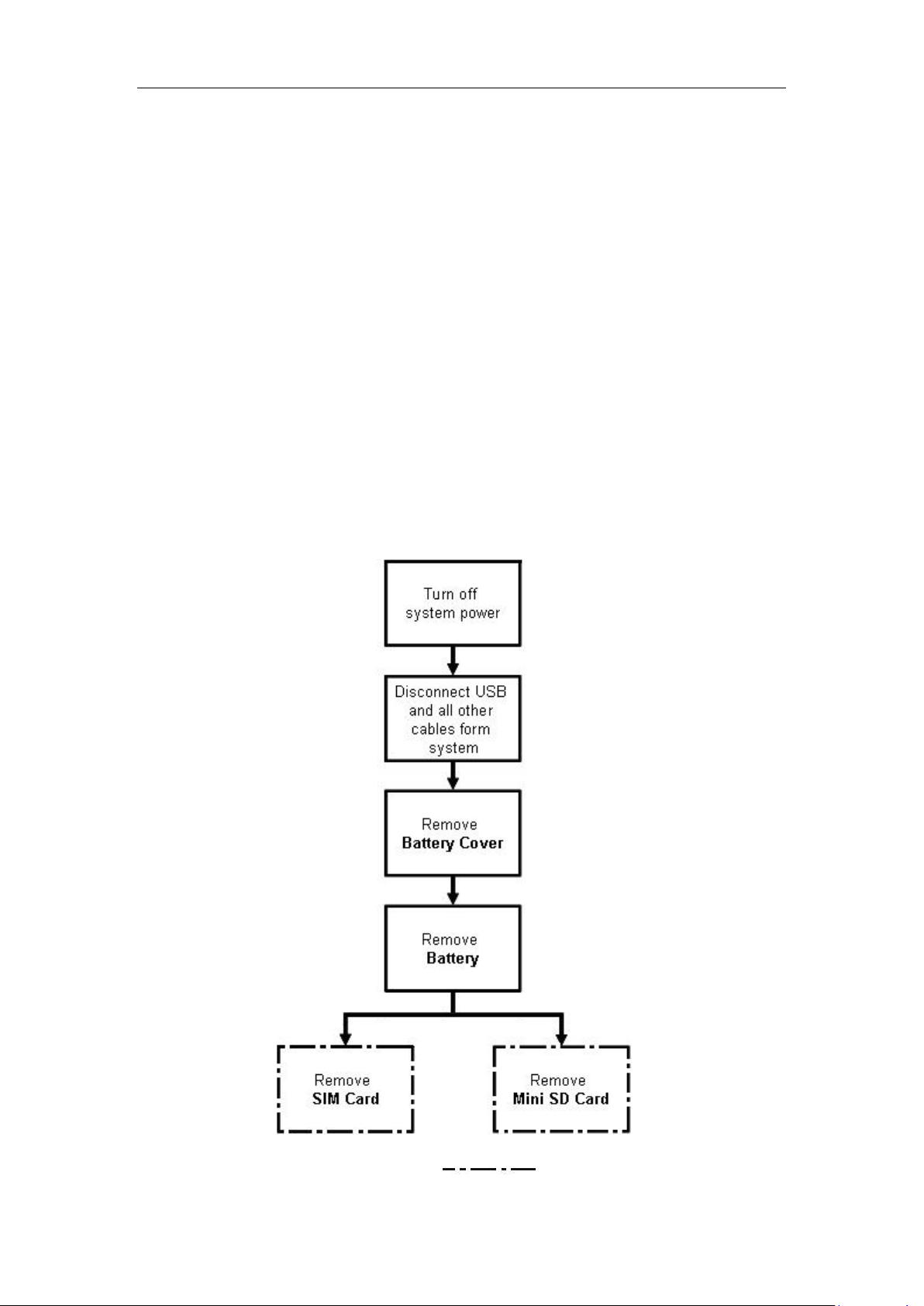
The following flowcharts provided in succeeding disassembly sections illustrate the entire
disassembly sequence. Observe the order of the sequence to avoid damage to any of the hardware
components.
NOTE: Torque is 0.9±0.1kgf/mm and driver speed is lower than 750 rpm
External Module Disassembly Process
External Module Disassembly Flowchat
NOTE: Items enclosed with broken lines ( ) are optional and may not be present.
20 / 66
Page 21
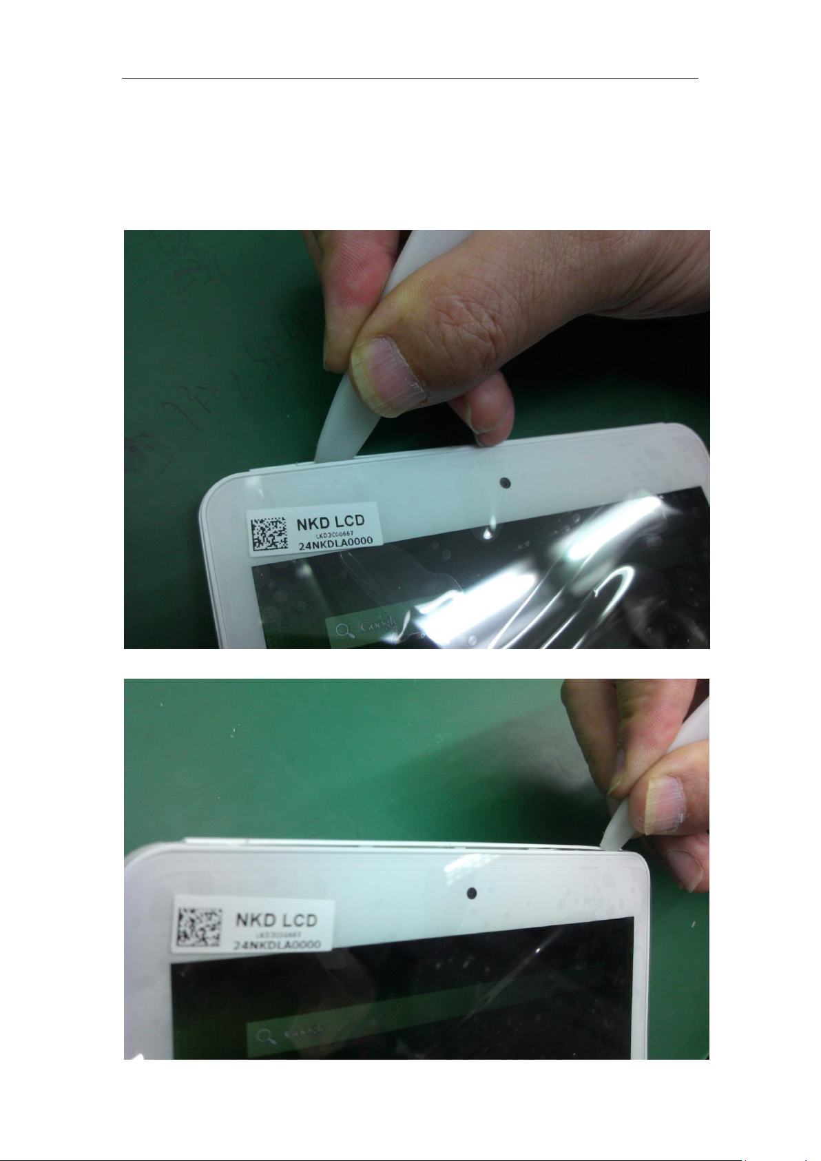
Removing the Battery Cover
1、 insert the plectrum into the gap of the left top side
2、 gash the unit from left side to right side
21 / 66
Page 22
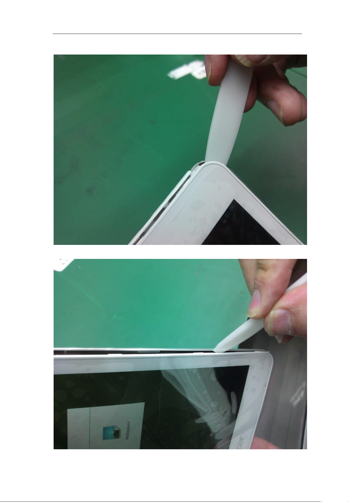
3、 open the corner of rear housing using the plectrum
4、 gash from the right top side directly to the right bottom side,take out the plectrum.
22 / 66
Page 23
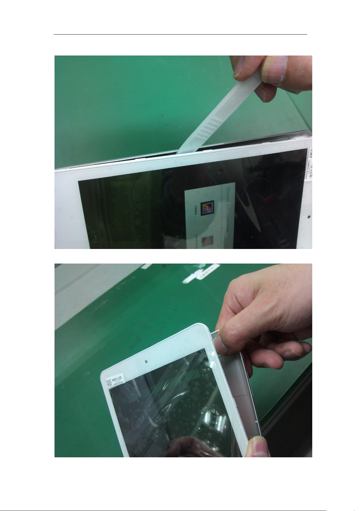
5、 insert the plectrum into the left top corner,gash to the left bottom corner. Take out the plectrum.
6、 hold the whole unit bottom with left hand, open the rear housing, take away the rear housing.
23 / 66
Page 24
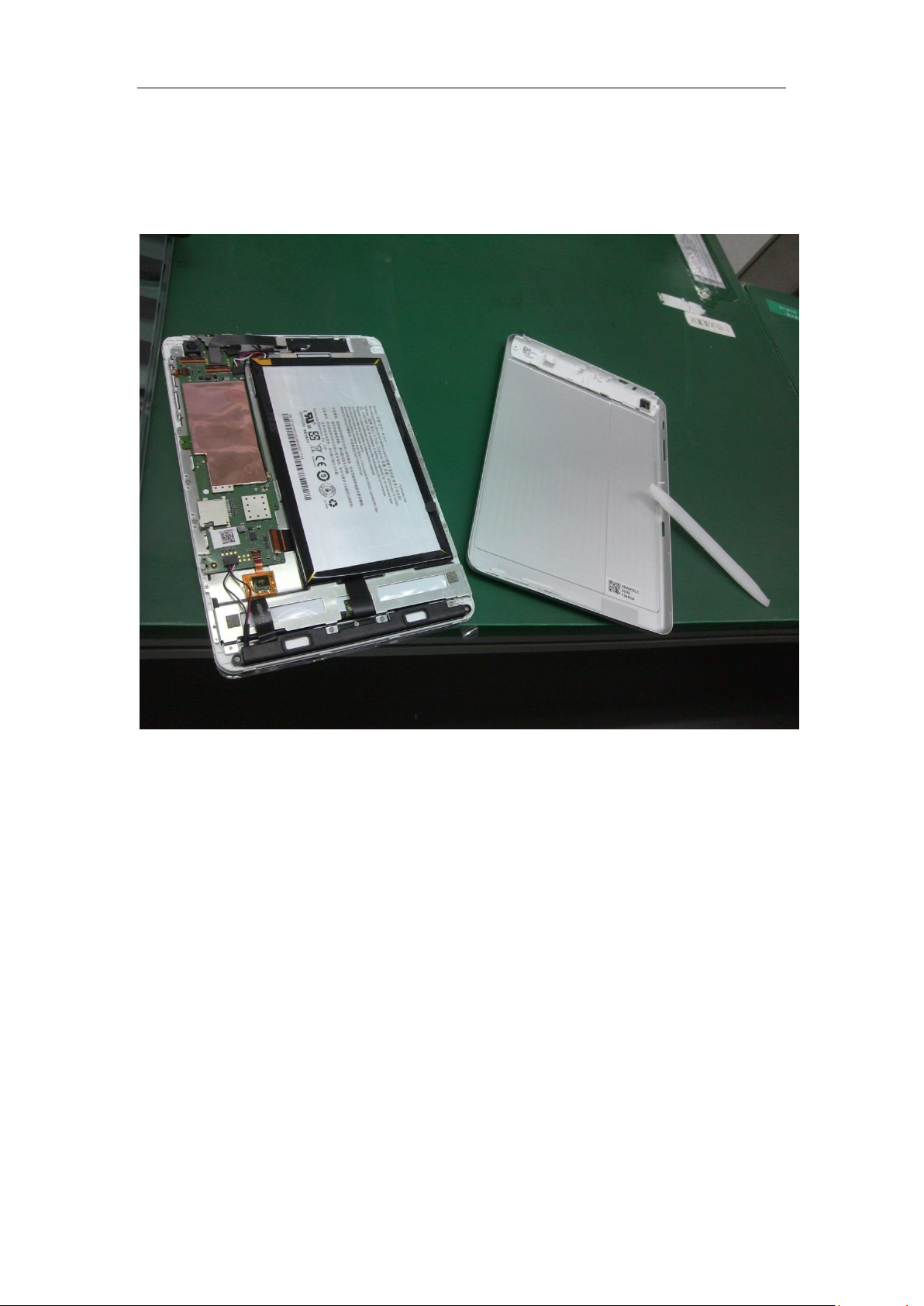
Remove the rear housing
24 / 66
Page 25
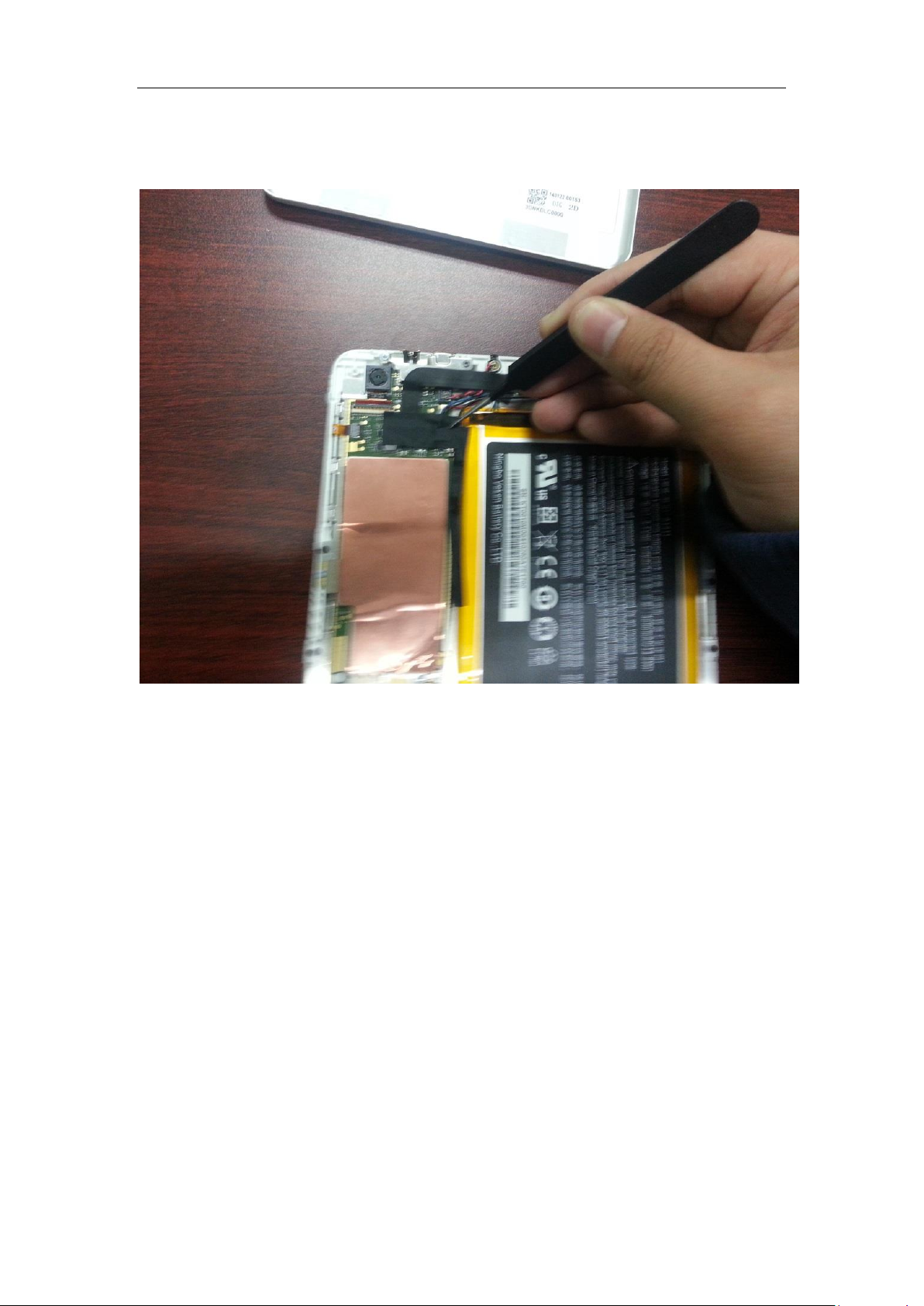
Uncover the acetate tape which covering the camera connectors
25 / 66
Page 26
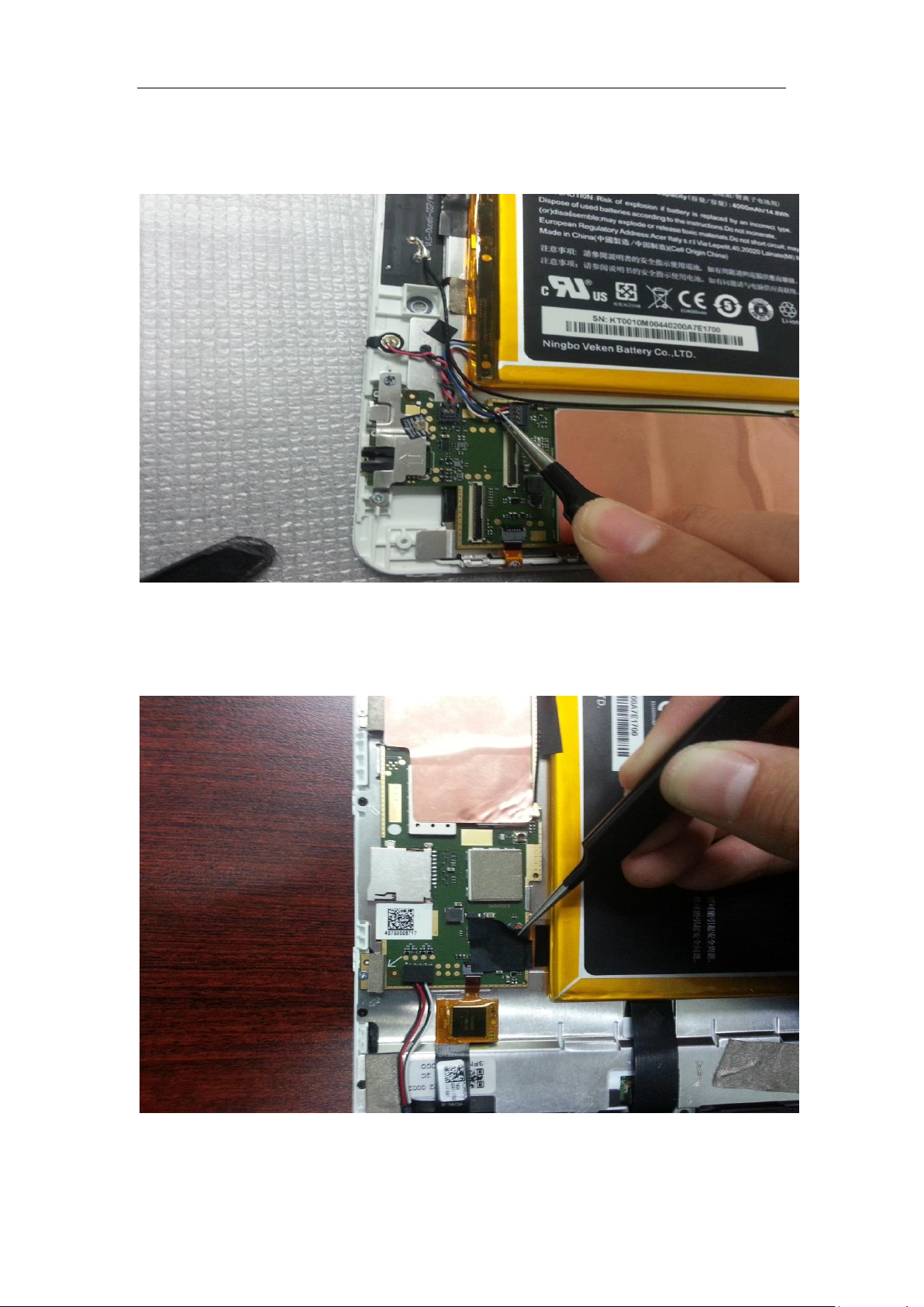
Unlock the Battery connector
Uncover the acetate tape which covering the LCD connector
26 / 66
Page 27
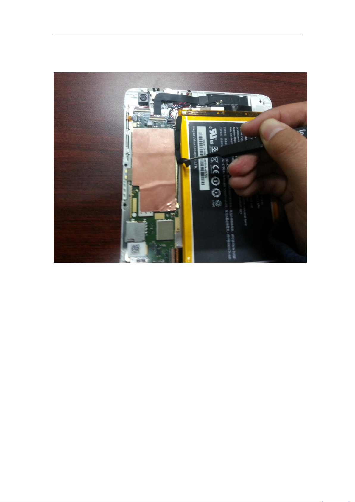
Uncover the acetate tape which covering the RF cable
27 / 66
Page 28
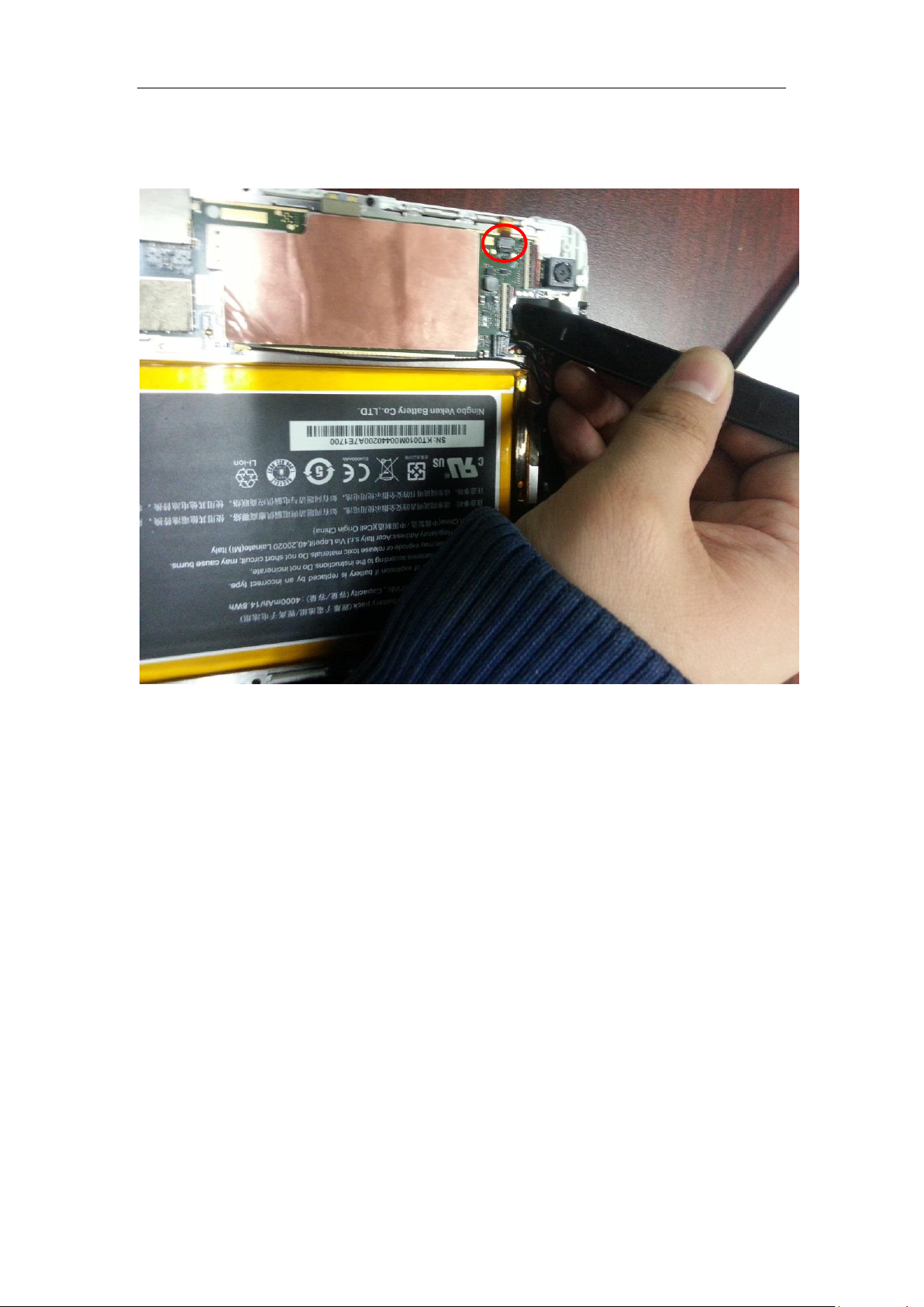
Unlock the side key FPC
28 / 66
Page 29
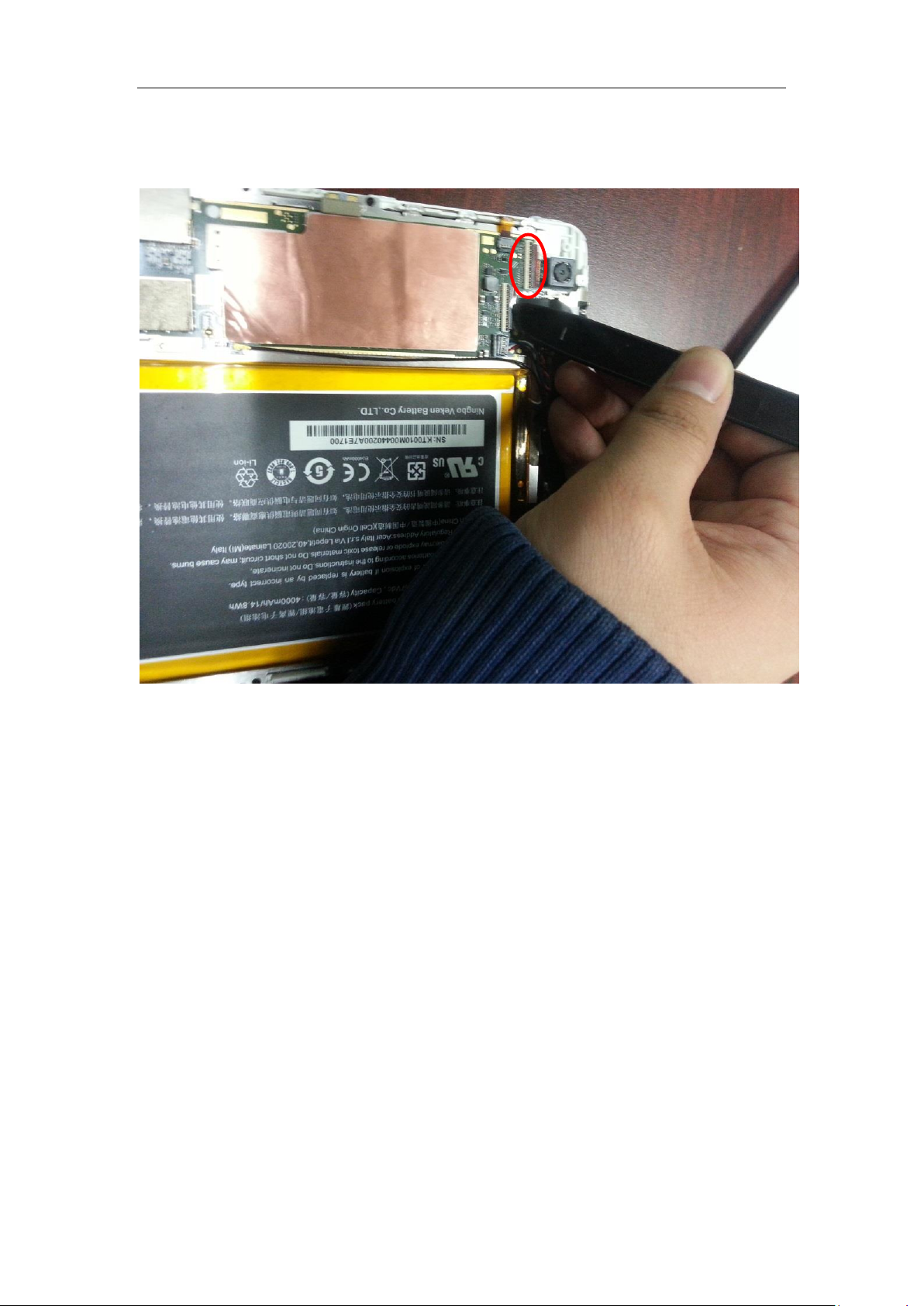
Unlock the rear camera connector and pull out the FPC
29 / 66
Page 30
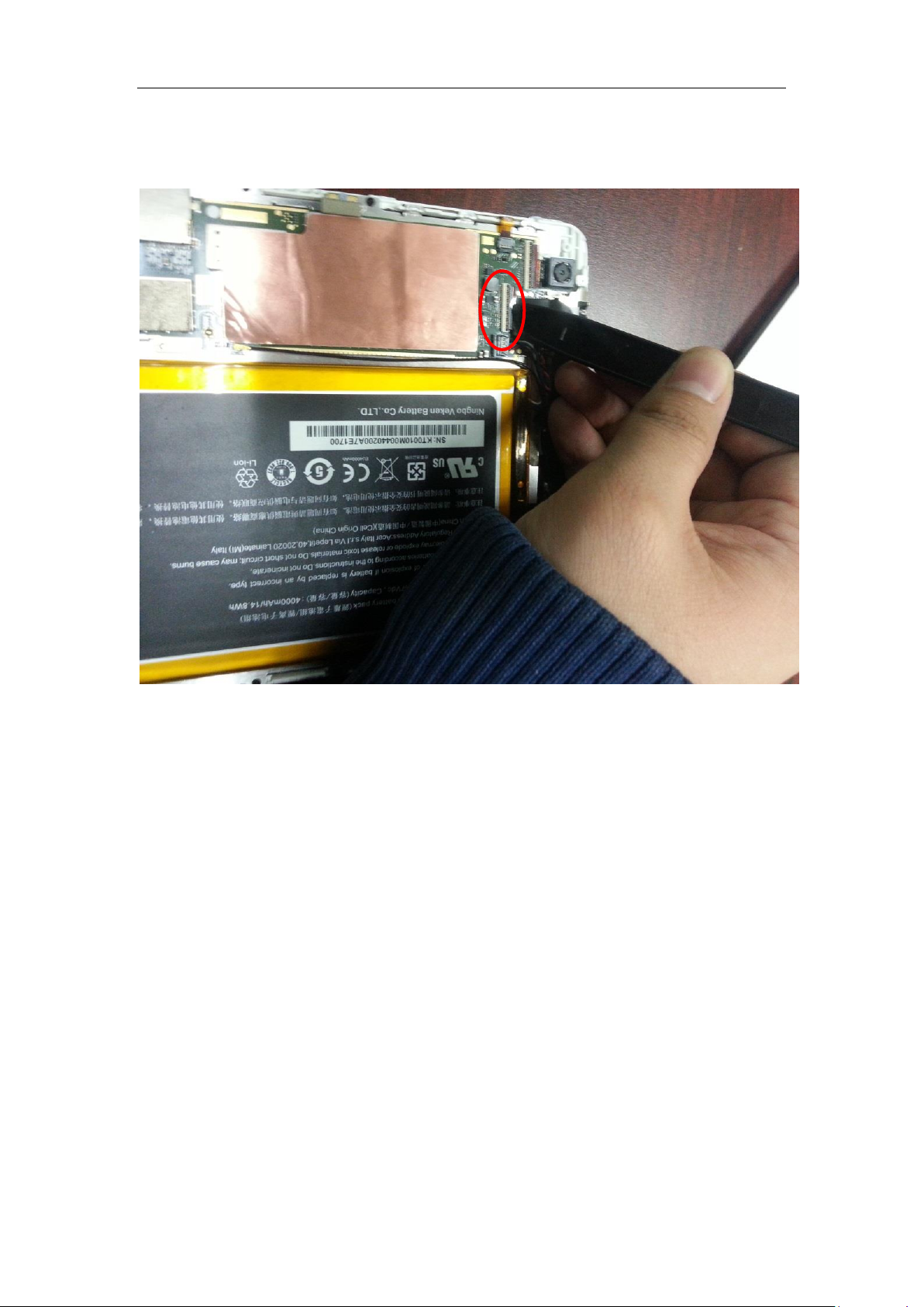
Unlock the front camera connector and pull out the FPC
30 / 66
Page 31
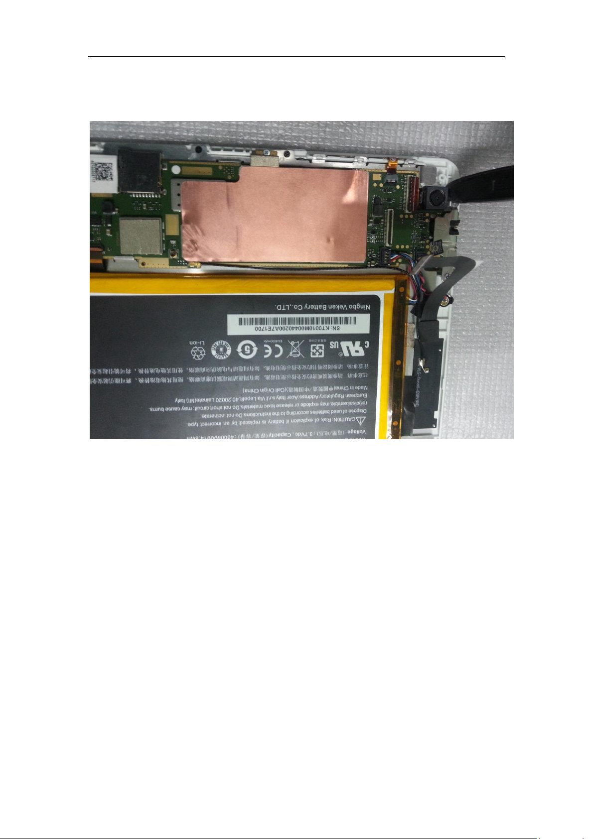
Remove the rear camera
31 / 66
Page 32
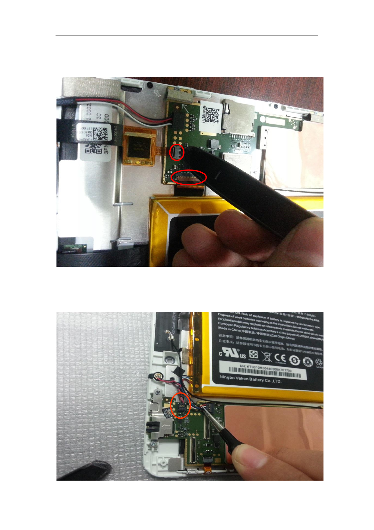
Unlock the TP connector and LCD FPC connectoe
Unlock the mic connectoe
32 / 66
Page 33
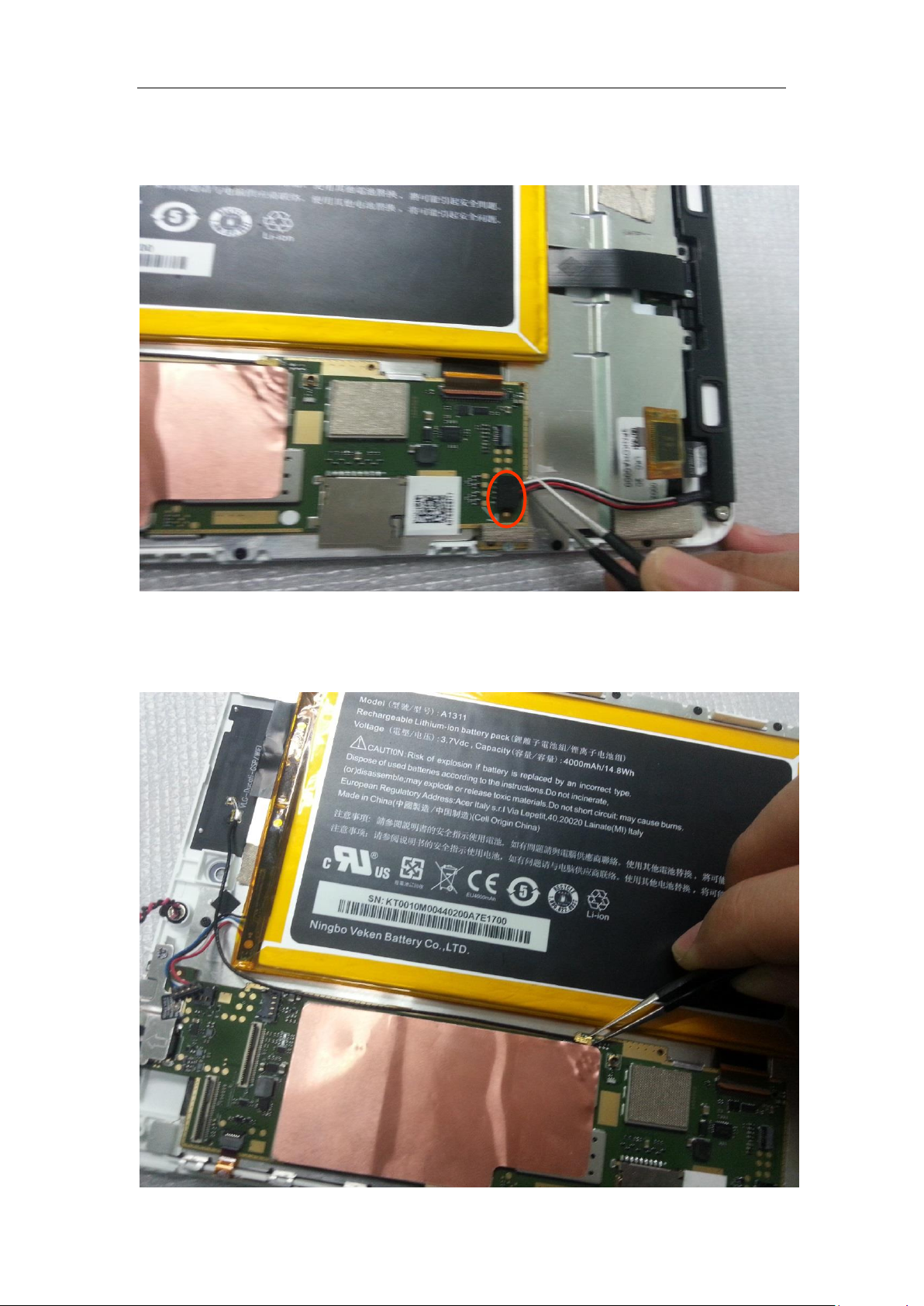
Unlock the speaker connector
Unlock the RF cable connector
33 / 66
Page 34
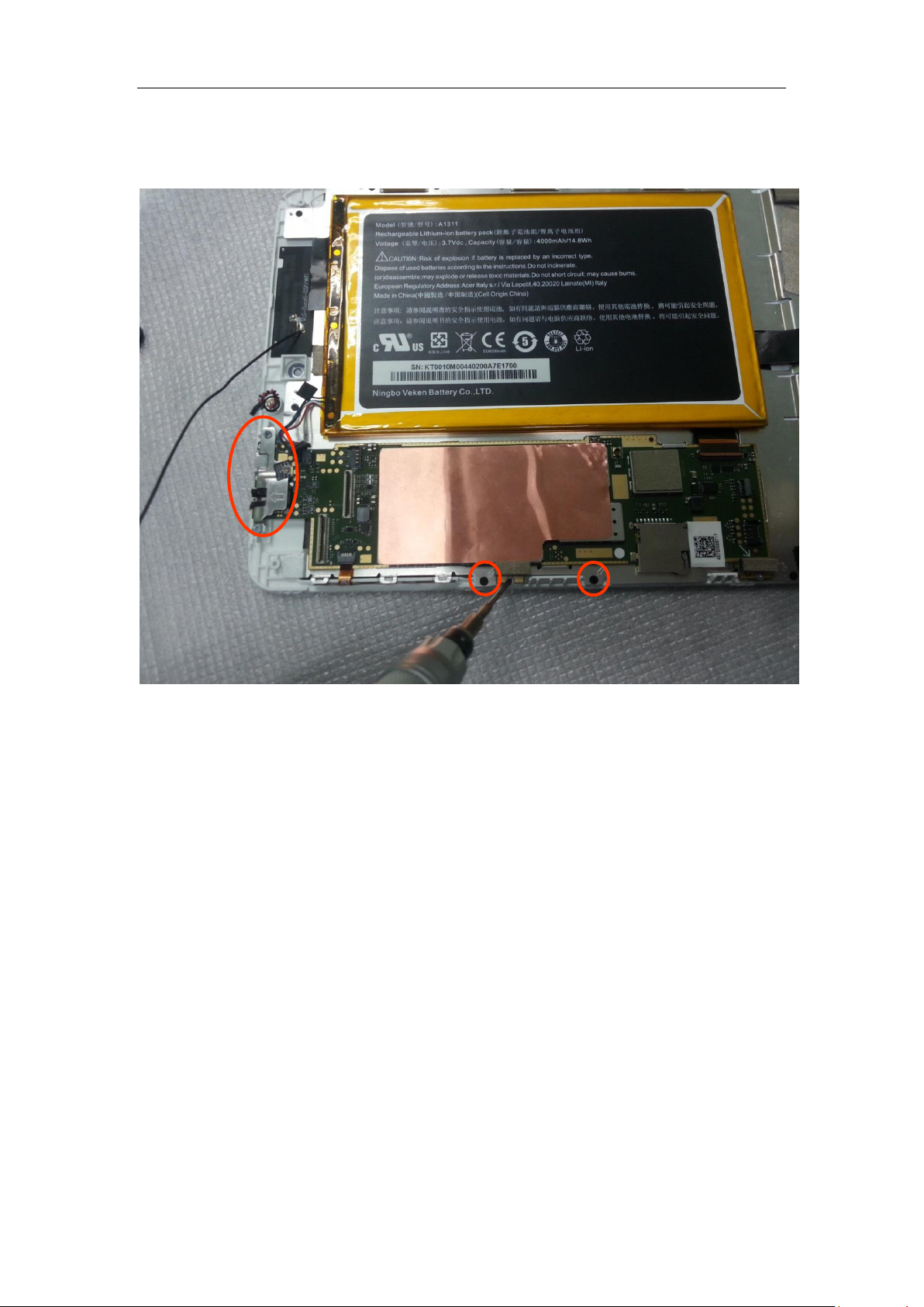
Release 5pcs screws shown in the picture
34 / 66
Page 35
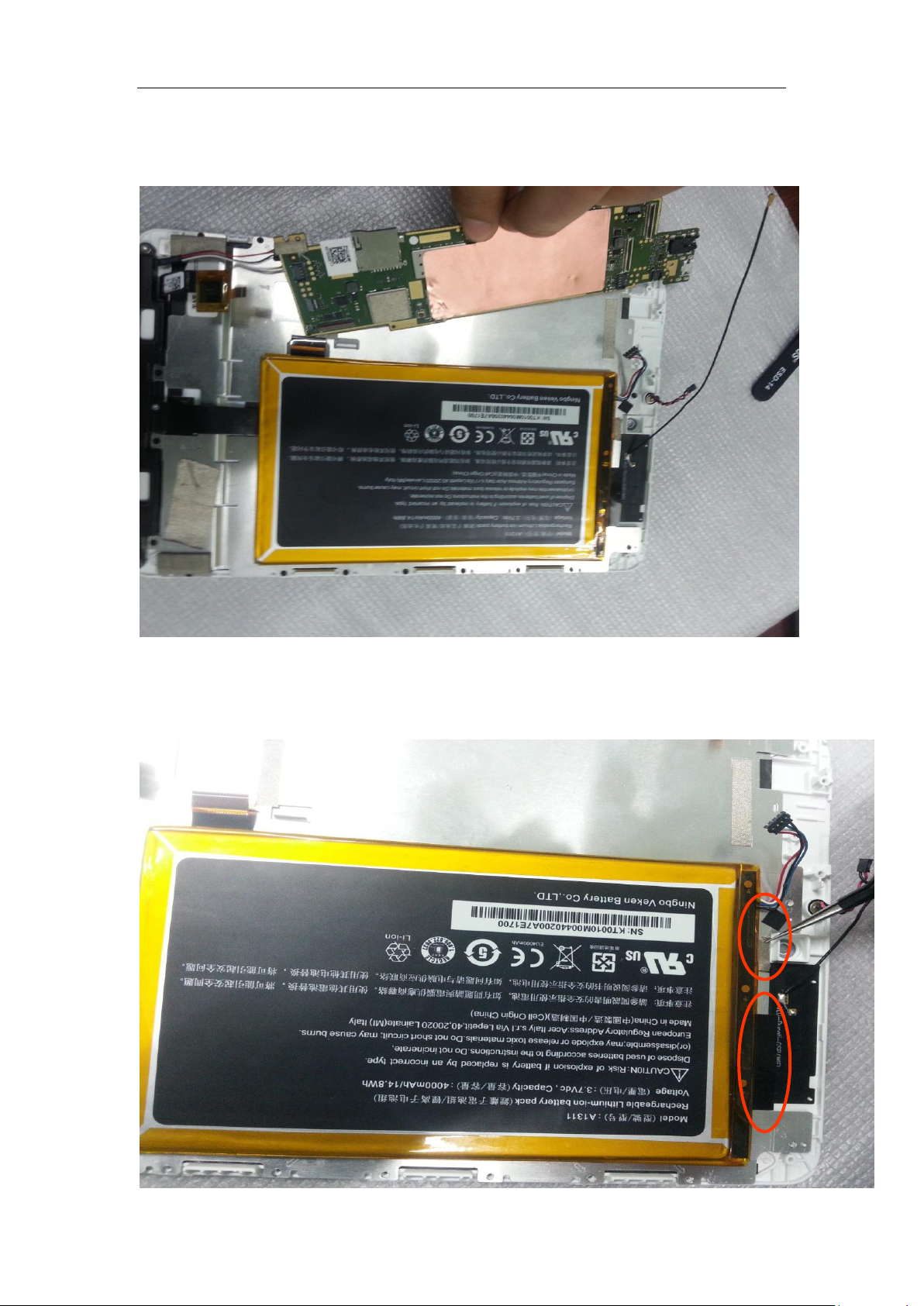
Remove the PCBA
Uncover the tape of the antenna carefully
35 / 66
Page 36
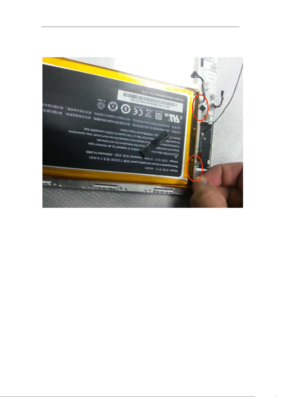
Pinch the tape of the Battery adhesive and remove the Battery
36 / 66
Page 37
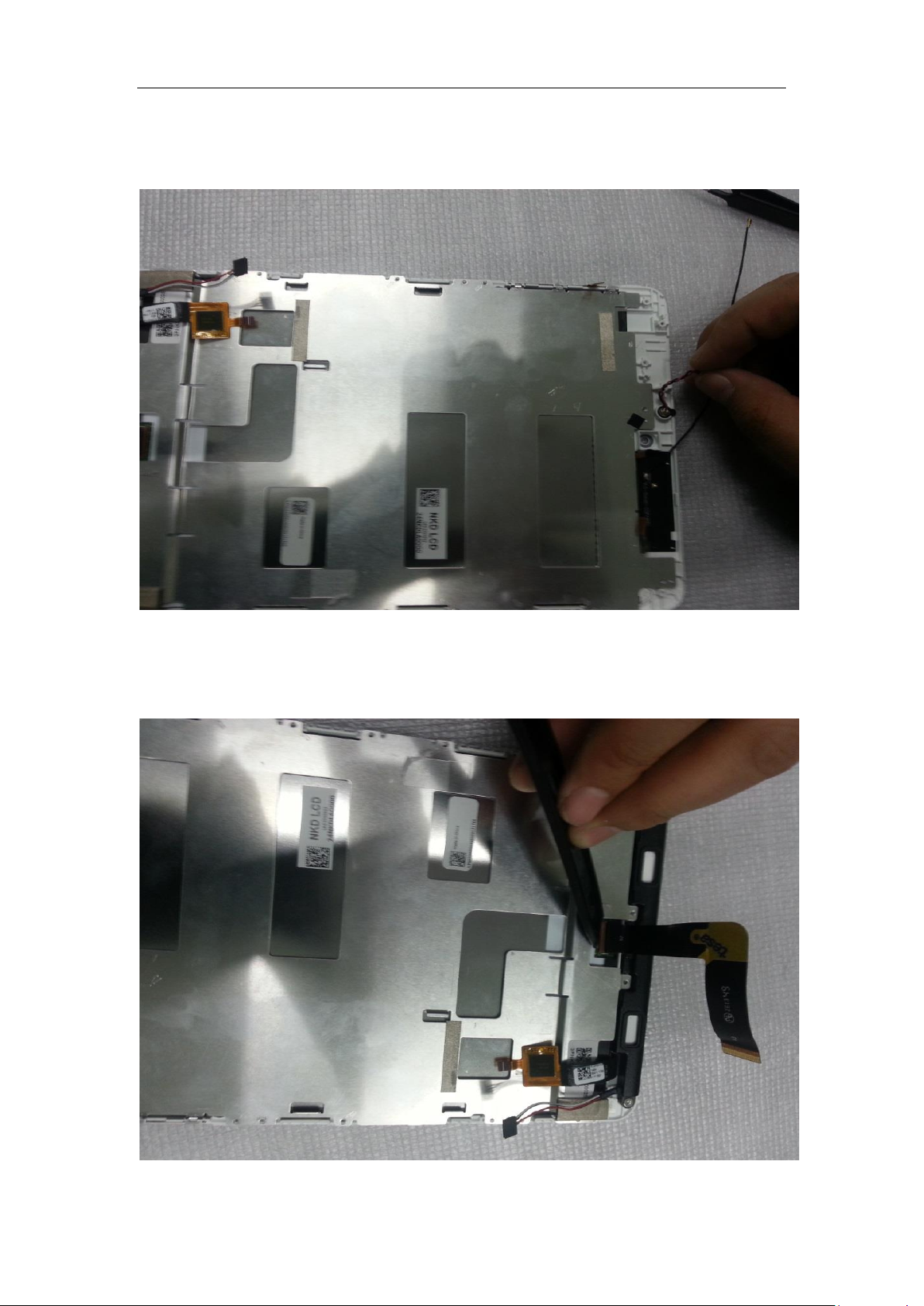
Pull out the mic carefully
Remove the foam on the LCD FPC connector and release the FPC
37 / 66
Page 38
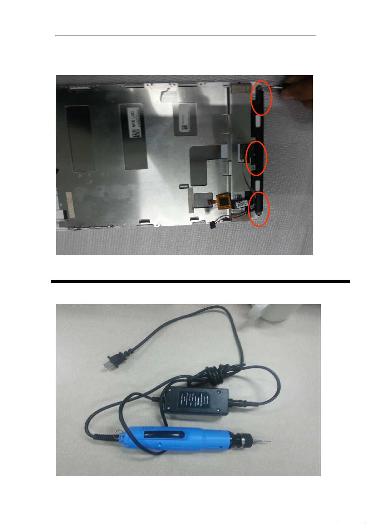
Unlock the 3pcs screws of the speaker box and removr the box
Required tools and screws
Electric screw driver
38 / 66
Page 39
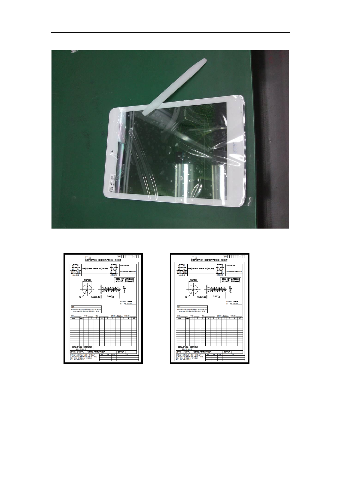
Plastic plectrum
The specification of the required 2 kinds of screw
39 / 66
Page 40

CHAPTER4
Diagnostic Tool SOP
When you change MB, you should process below items
1. Re-write SNID
2. Re-write wifi country code
3. Calibrate Accelerometer
4. Do the diagnostic test
5. Flash correct OS
Ducati Service Tool(SN/ wifi country code)
1. Ducati Service Tool provides users with functions as following.
- Read/Write 22 characters Code SN,
- Read/Write wifi country code,
2. Required
Microsoft .NET Framework 4.0 is required.
Ducati device driver is required.
Ducati device shall have service ROM.
3. Re-write Acer 22 code SOP
1) Unzip “Acer_Ducati_acer22_code_v1.0.zip”
2) Open DOS window
3) Cd Acer_Ducati_acer22_code/ directory that you unzipped, like below:
40 / 66
Page 41
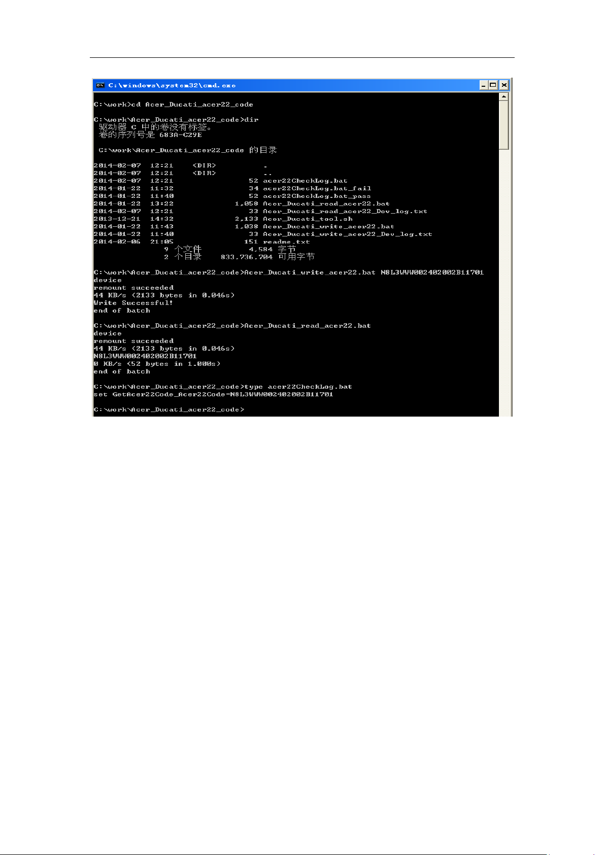
4) Run command:
Acer_Ducati_write_acer22.bat N8L3WWW002402002B11701
5) If you want to check what you write, you can run command:
Acer_Ducati_read_acer22.bat
Then run command:
type WIFIcountryCheckLog.bat
You will see “set GetAcer22Code_Acer22Code=N8L3WWW002402002B11701”, that means
your Ducati‟s Acer 22 code that you write is “N8L3WWW002402002B11701”.
4. Re-write country code SOP
1) Unzip “Acer_Ducati_WIFIcountry_code_v1.0.zip”
2) Open DOS window
3) Cd Acer_Ducati_WIFI country_code/directory that you unzip,like below
41 / 66
Page 42
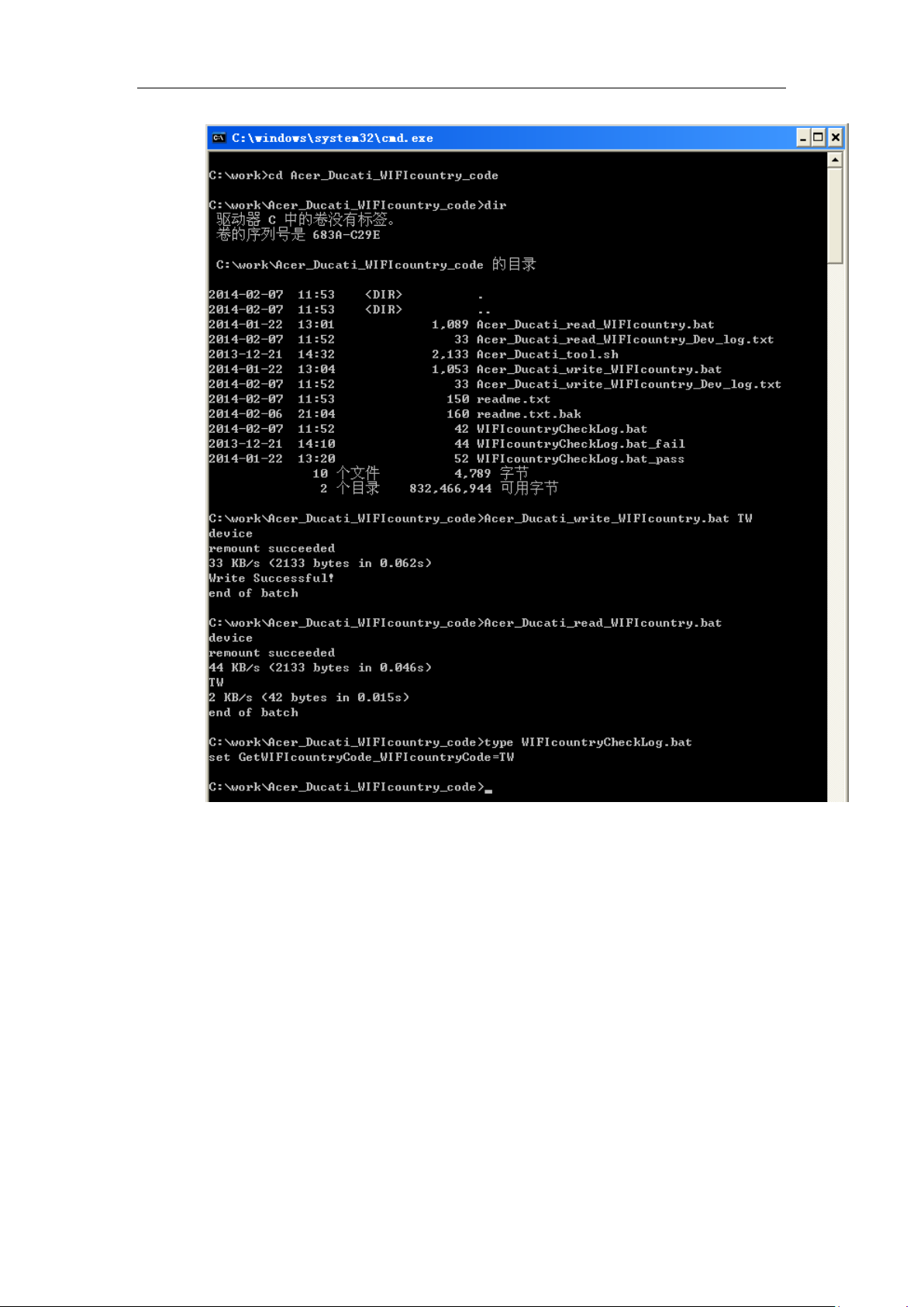
4) Run command:
Acer_Ducati_write_WIFIcountry.bat TW
5) If you want to check what you write, you can run command:
Acer_Ducati_read_WIFIcountry.bat
Then run command:
type WIFIcountryCheckLog.bat
You will see “set GetWIFIcountryCode_WIFIcountryCode=TW”, that means your Ducati‟s WIFI
Country code that you write is “TW”
42 / 66
Page 43
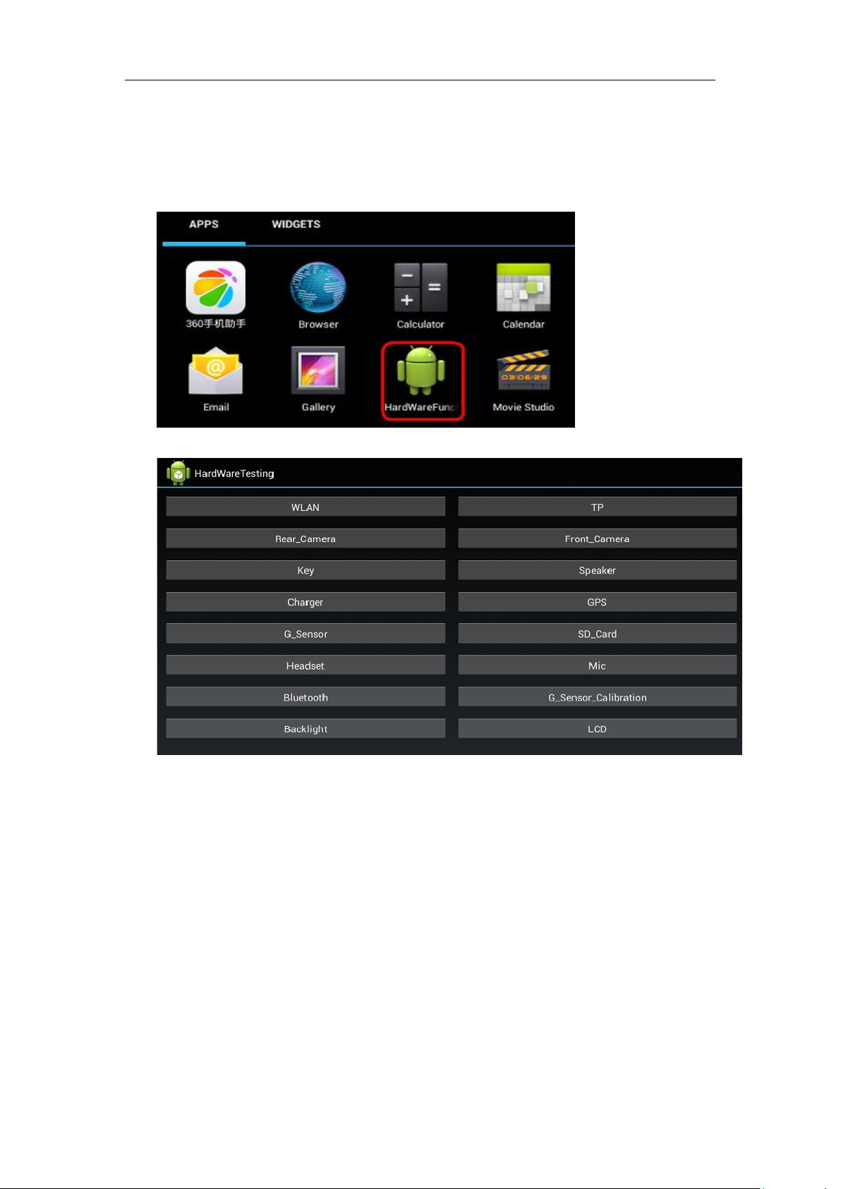
How to Enter in Hardware Testing Mode
Press the MENU button, and click on ICON “HardWareFunctionTest” in APPS, press the button to
perform the function that you want to do.as shown in figure 1.1 and figure 1.2.
Figure 1.1
Hardware Testing Items
Backlight Test
Key Test
Front_Camera Test
Rear_Camera Test
SD_Card Test
TP Test
LCD Test
Headset Test
G_Sensor Test
Charger Test
Bluetooth Test
43 / 66
Figure 1.2
Page 44
Speaker Test
Mic Test
WLAN Test
GPS Test
G_Sensor_Calibration Test
Hardware Testing Items Using Guid
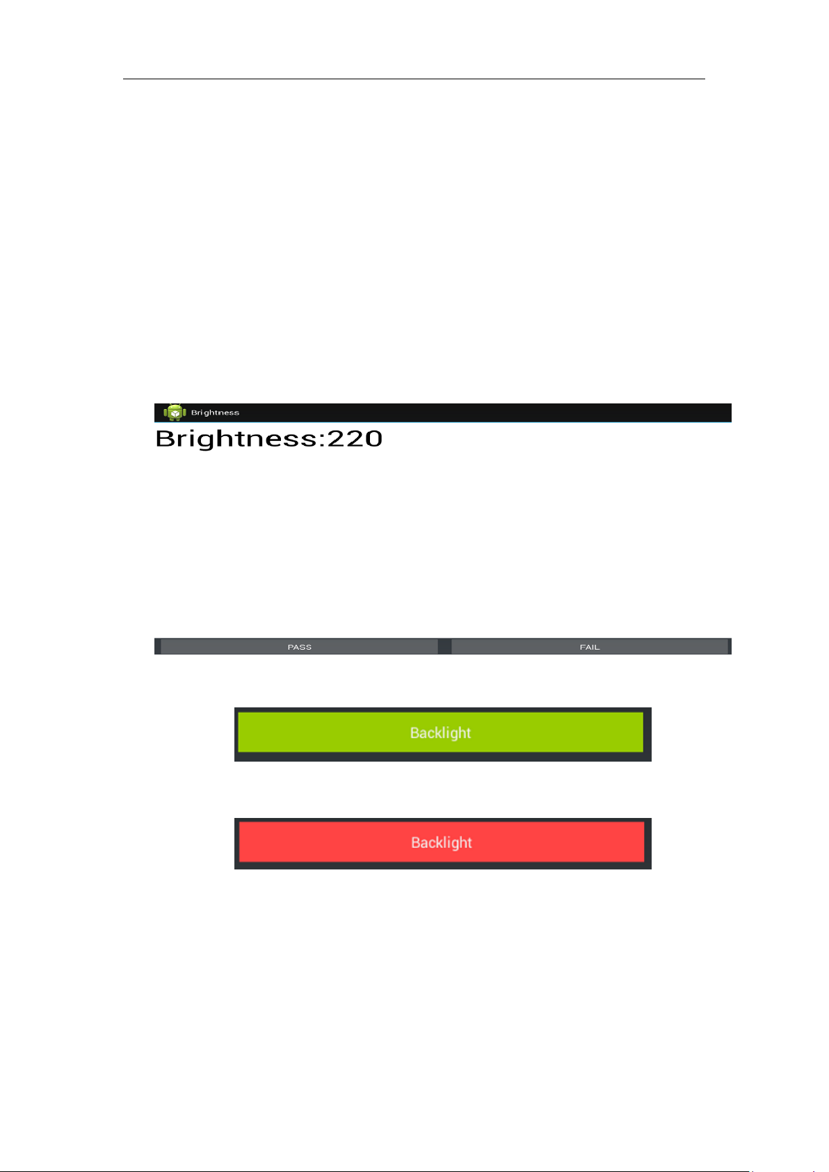
Backlight:
Backlight test, show backlight Level20-Level120-Level220 successively, and then according
to the actual result that you saw to choose PASS or FAIL, as shown in figure 3.1(a).
Figure3.1(a)
Green button means PASS, Red button means FAIL, as shown in figure 3.1(b) and 3.1(c).
Figure 3.1(b)
Figure 3.1(c)
KEY:
• Follow the picture‟s instruction to press related key successively. If the key function is passed
then the related key button will disappear.
• Key includes:” Volume Up” & ” Volume Down”, Power key did NOT be tested.
44 / 66
Page 45
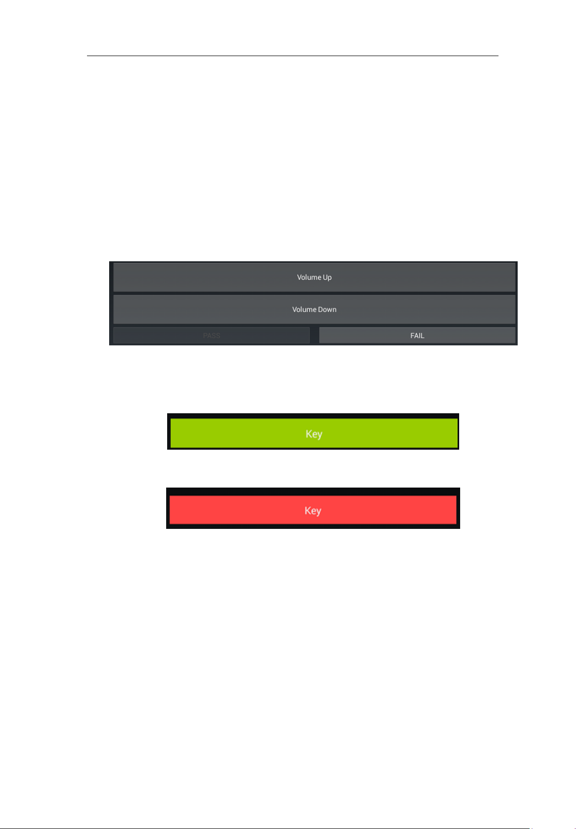
• Two key passed test then please choose PASS otherwise FAIL, as shown in figure 3.2(a).
Green button means PASS, Red button means FAIL, as shown in figure 3.2(b) and 3.2(c).
Front_Camera:
Figure 3.2(a)
Figure 3.2(b)
Figure 3.2(c)
Front Camera test, click on “Take Photo” button, it should take a picture by front camera,
check the picture and according to the actual result that you saw to choose PASS or FAIL.as shown
in figure 3.3(a).
45 / 66
Page 46
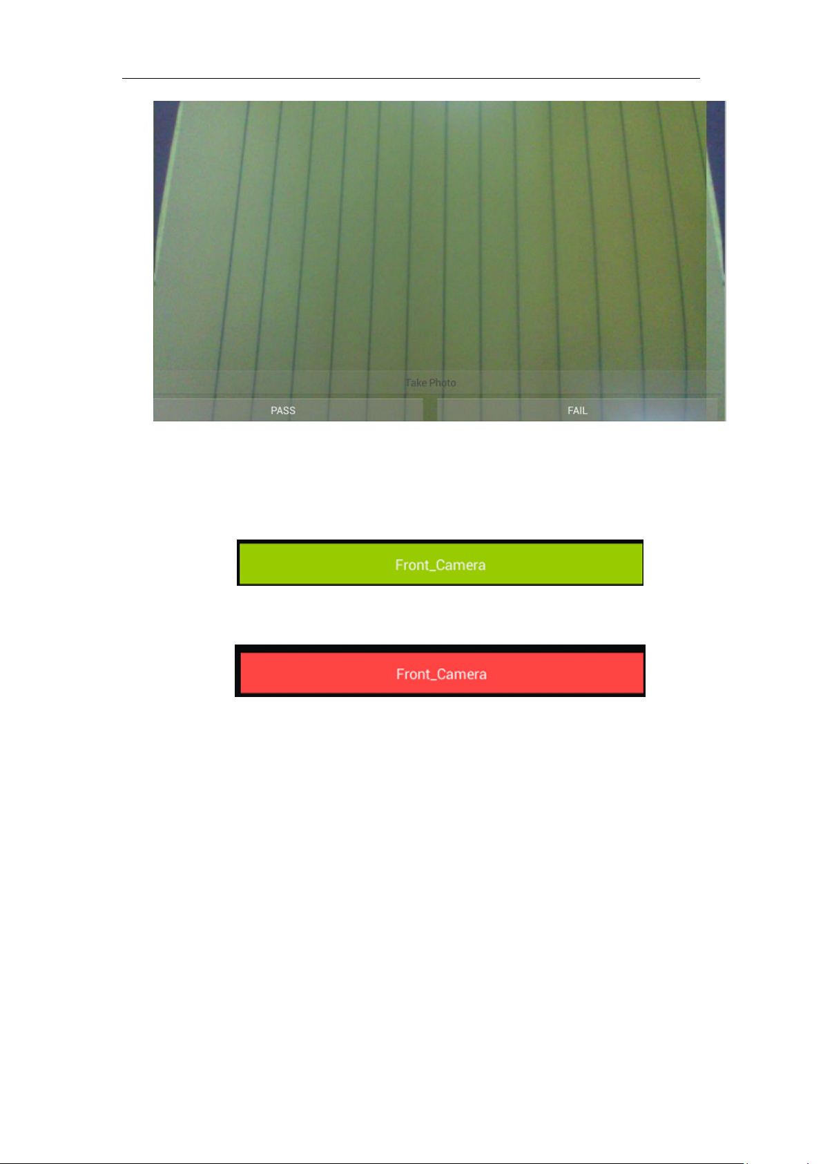
Figure 3.3(a)
Green button means PASS, Red button means FAIL, as shown in figure 3.3(b) and
3.3(c).
Figure 3.3(b)
Figure 3.3(c)
Rear_Camera:
Rear Camera test, click on “Take Photo” button, it should take a picture by rear camera, check
the picture and according to the actual result that you saw to choose PASS or FAIL.as shown in
figure 3.4(a).
46 / 66
Page 47
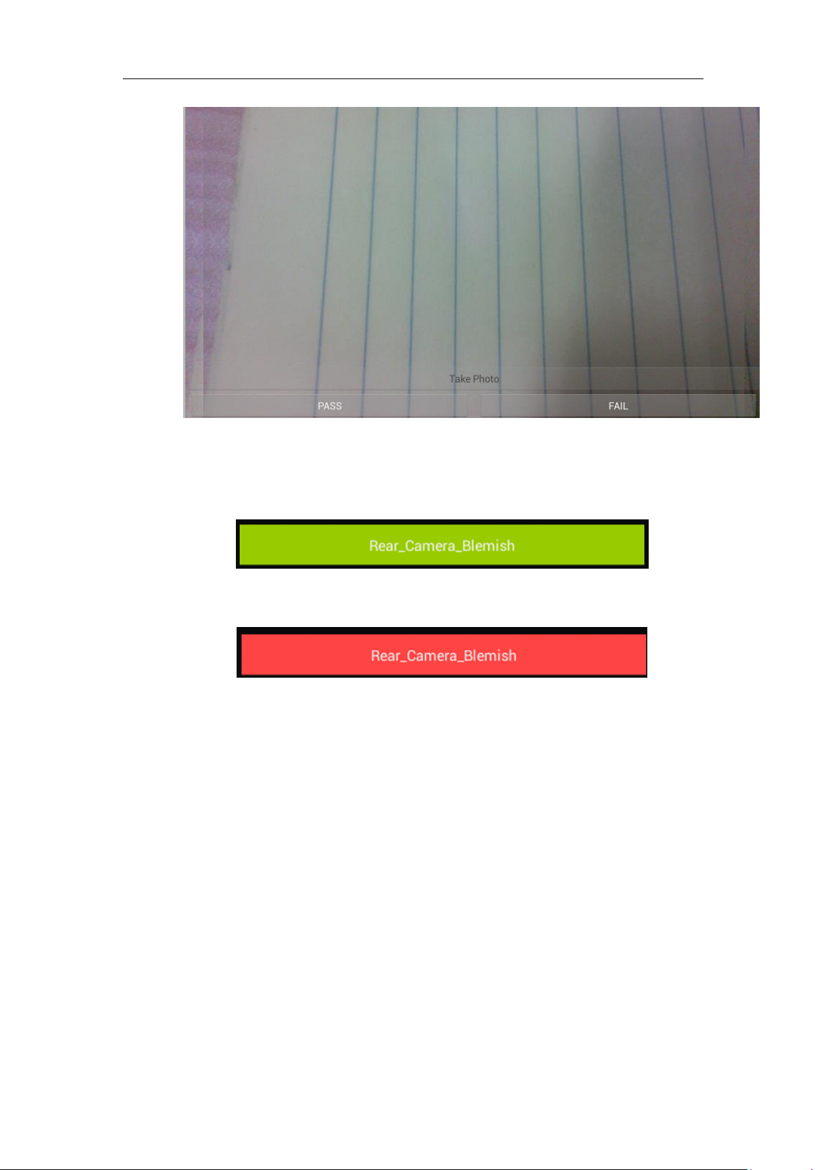
Figure 3.4(a)
Green button means PASS, Red button means FAIL, as shown in figure 3.4(b) and 3.4(c).
Figure 3.4(b)
Figure 3.4(c)
SD_Card:
SD card test, insert Micro SD card and then according to the test result which be displayed on
the screen to choose PASS or FAIL, as shown in figure 3.5(a) and 3.5(b).
47 / 66
Page 48
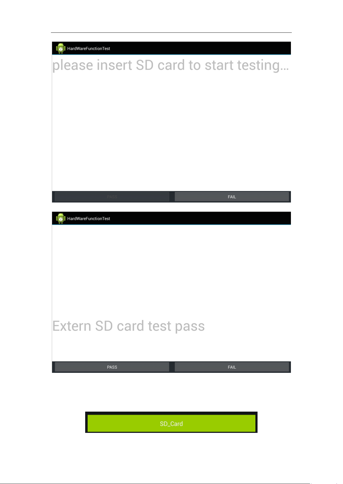
Figure 3.5(a)
48 / 66
Figure 3.5(b)
Green button means PASS, Red button means FAIL, as shown in figure 3.5(c) and 3.5(d).
Page 49
TP:
Figure 3.5(c)
Figure 3.5(d)
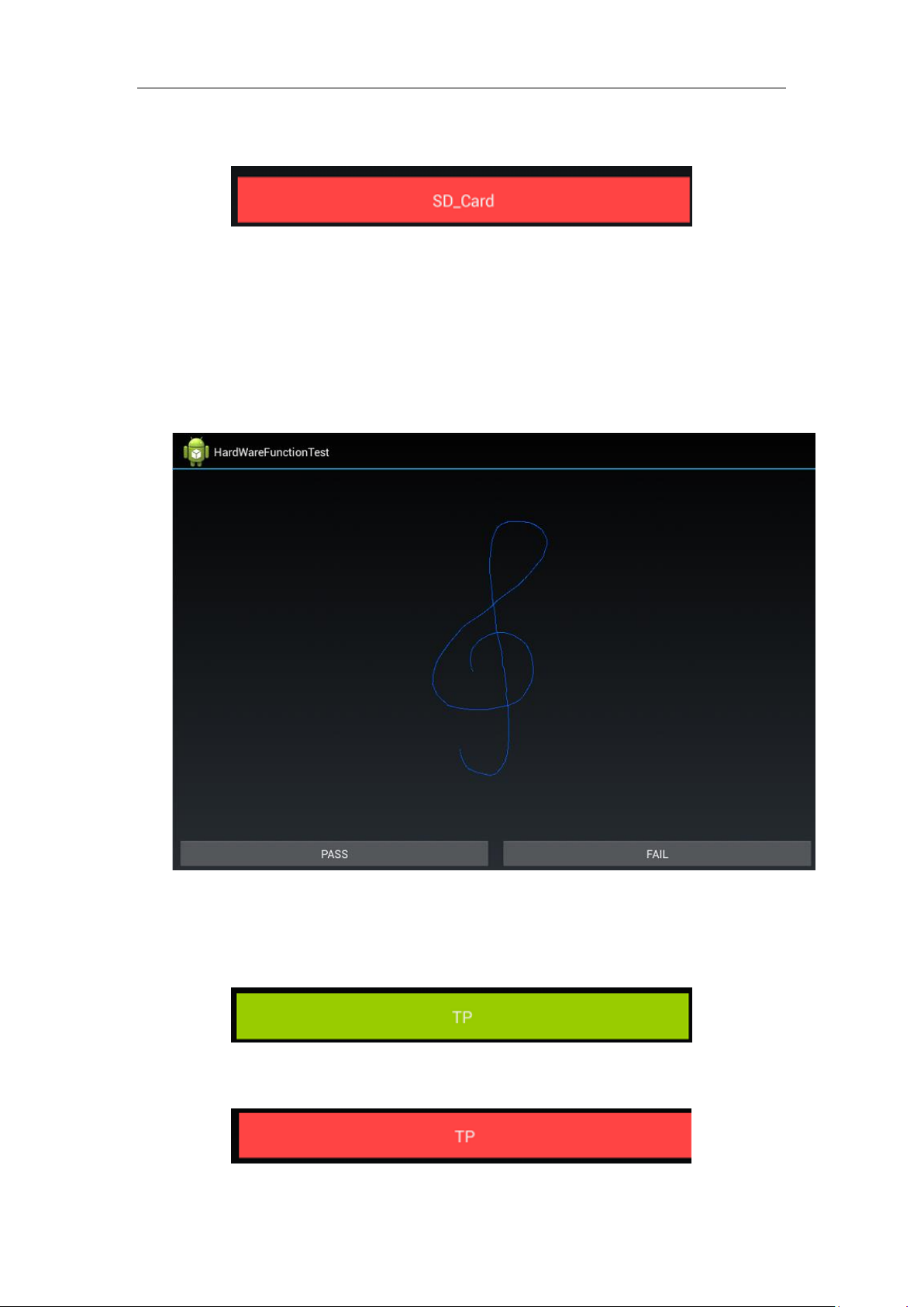
TP test, random test and then choose PASS or FAIL, as shown in figure 3.6(a).
49 / 66
Figure 3.6(a)
Green button means PASS, Red button means FAIL, as shown in figure 3.6(b) and 3.6(c).
Figure 3.6(b)
Page 50
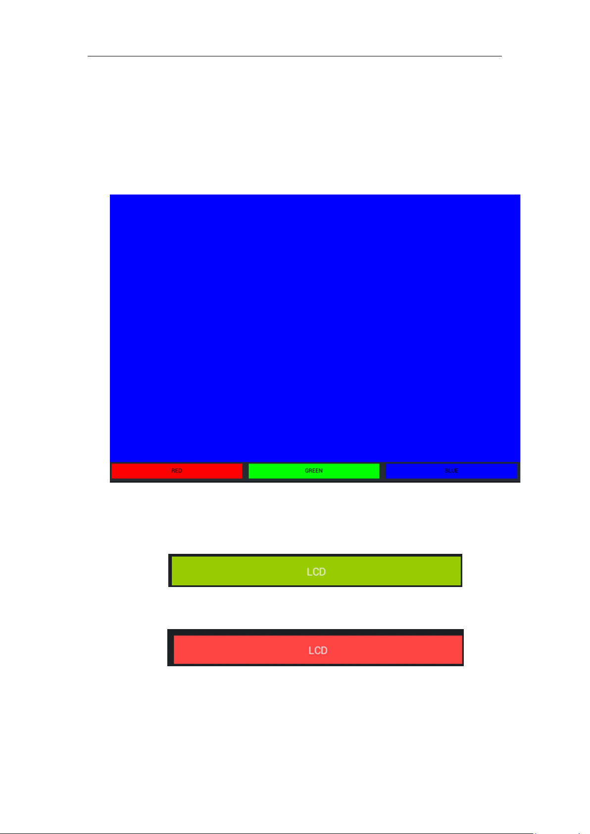
Figure 3.6(c)
LCD:
LCD test, many and different colors(W/B/R/G/B) be displayed to the screen, and then let you choose
which color do you see on screen finally, RED or GREEN or BLUE, as shown in figure 3.7(a).
Figure 3.7(a)
Green button means PASS, Red button means FAIL, as shown in figure 3.7(b) and 3.7(c).
Figure 3.7(b)
Figure 3.7(c)
50 / 66
Page 51
Headset:
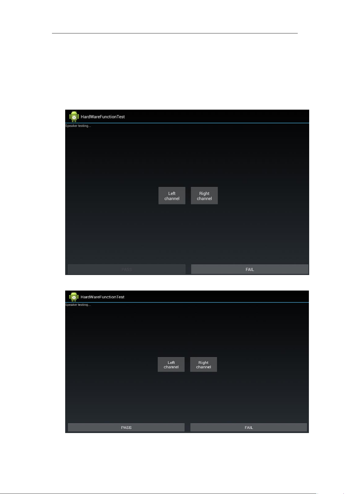
Headset test, insert headset and then click on “Left channel” and “Right channel” successively, If hear the
sound only from corresponding headset side, choose PASS;otherwise choose FAIL.as shown in figure
3.8(a) and 3.8(b).
Figure 3.8(a)
Figure 3.8(b)
51 / 66
Page 52
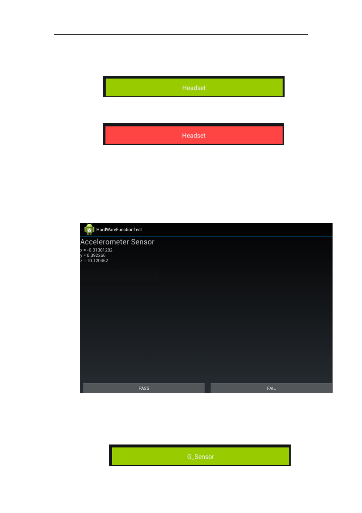
Green button means PASS, Red button means FAIL, as shown in figure 3.8(b) and 3.8(c).
G_Sersor:
Figure 3.8(c)
Figure 3.8(d)
G Sensor test, coordinate X/Y/Z will be changed to corresponding value when DUT be moved
or be changed place, According to this please choose PASS or FAIL, as shown in figure 3.9(a).
52 / 66
Figure 3.9(a)
Green button means PASS, Red button means FAIL, as shown in figure 3.9(b) and
3.9(c).
Page 53
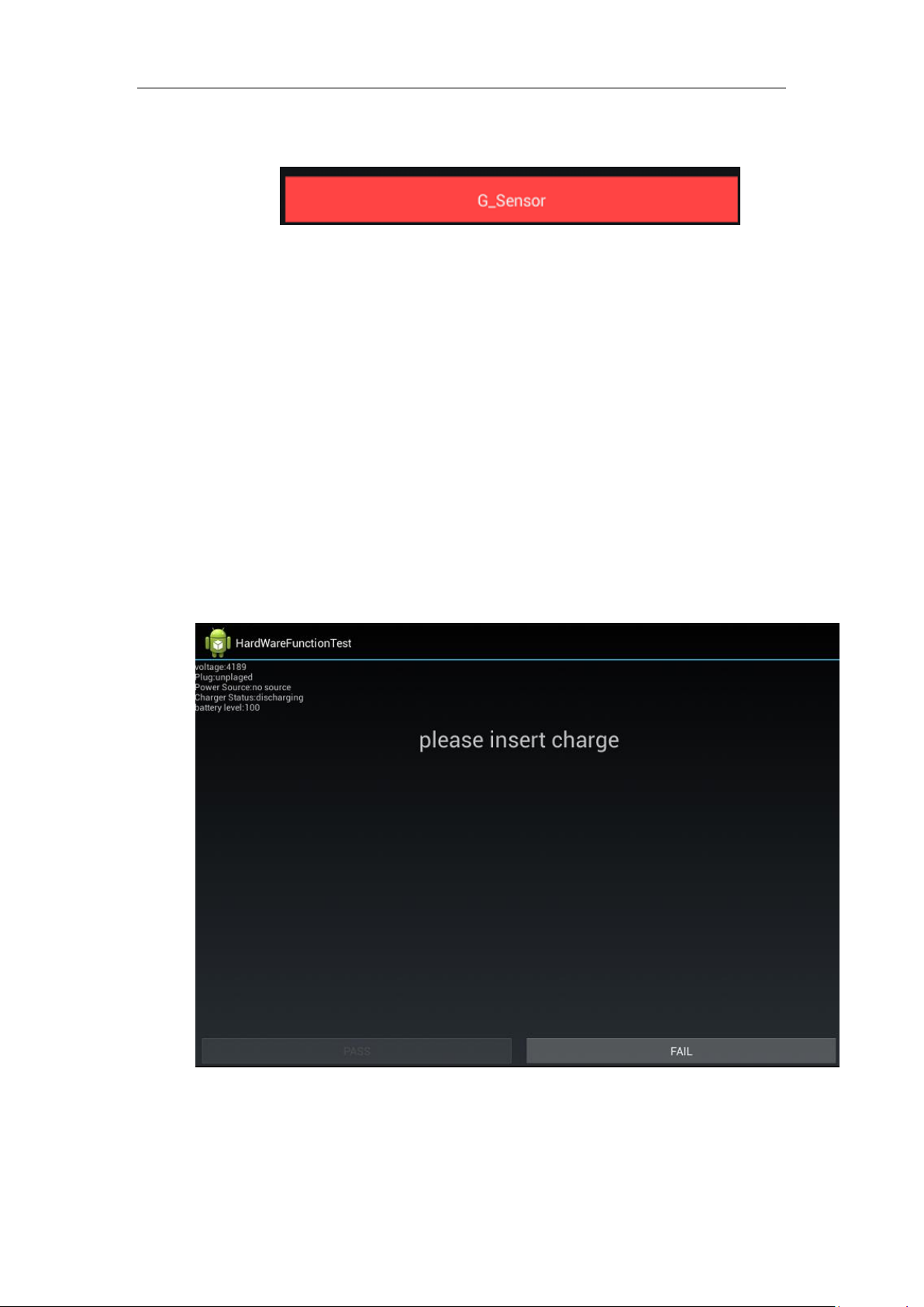
Figure 3.9(b)
Figure 3.9(c)
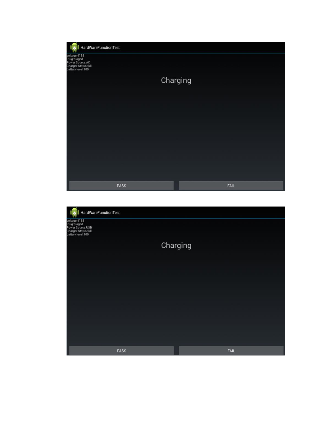
Charger:
Charger test.
• Insert AC adapter.
• Pass Criteria:
- Voltage:3000 ~ 4250
- Plug : plugged
- Power Source: AC or USB
- Charger Status:Charging or Full
- Battery Level:0 ~ 100
- Show “Charging” on screen
• According to this please choose PASS or FAIL,as shown in figure 3.10(a) & 3.10(b) & 3.10(c).
•
• Figure 3.10(a)
53 / 66
Page 54
•
• Figure 3.10(b)
•
• Figure 3.10(c)
•
•
•
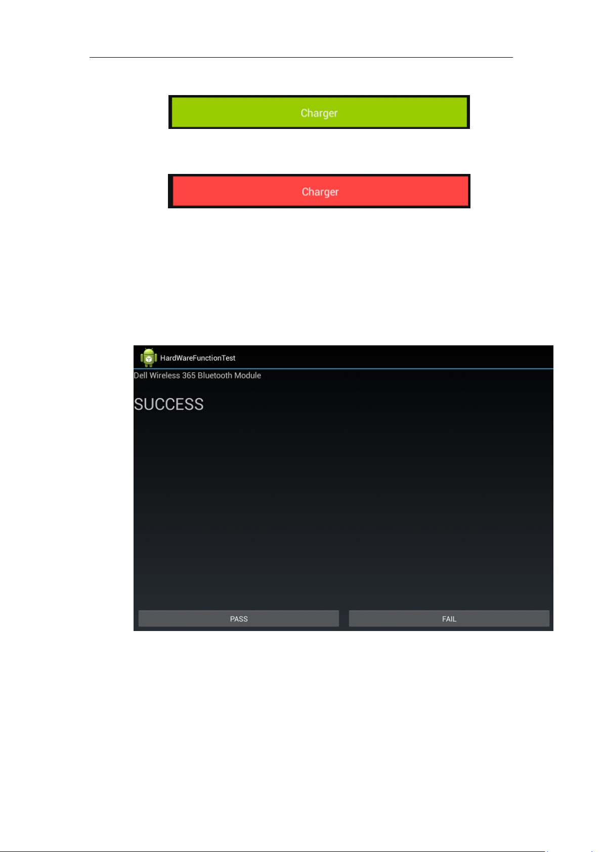
• Green button means PASS, Red button means FAIL, as shown in figure 3.10(d) and 3.10(e).
54 / 66
Page 55
•
•
• Figure 3.10(d)
•
•
• Figure 3.10(e)
Bluetooth:
Bluetooth test, it will scanning device, according to the test result which be displayed on screen to choose
PASS or FAIL, as shown in figure 3.11(a) and 3.11(b).
55 / 66
Figure 3.11(a)
Page 56
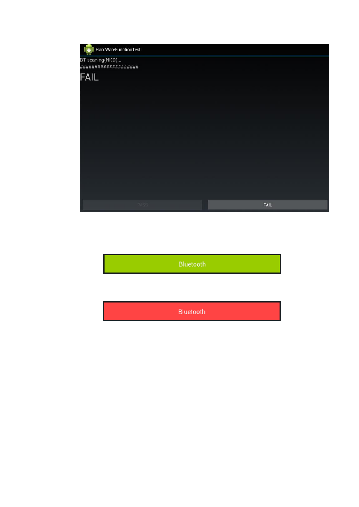
Figure 3.11(b)
Green button means PASS, Red button means FAIL, as shown in figure 3.11(c) and 3.11(d).
Figure 3.11(c)
Figure 3.11(d)
Speaker:
Speaker test, press “Left channel” button and “Right channel” button successively, If hear the
sound only from corresponding speaker side, choose PASS;otherwise choose FAIL.as shown in
figure 3.12(a).
56 / 66
Page 57
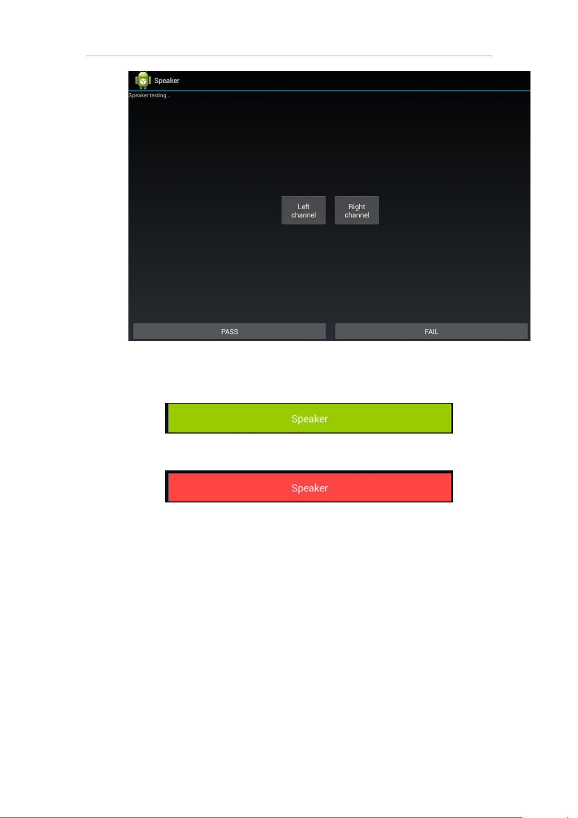
Figure 3.12(a)
Green button means PASS, Red button means FAIL, as shown in figure 3.12(b) and 3.12(c).
Figure 3.12(b)
Figure 3.12(c)
MIC:
MIC test, press “start record” button and recording the voice, when it‟s finished, you will hear
this voice from MIC then output to speaker. According to this please choose PASS or FAIL, as
shown in figure 3.13(a) and 3.13(b).
57 / 66
Page 58
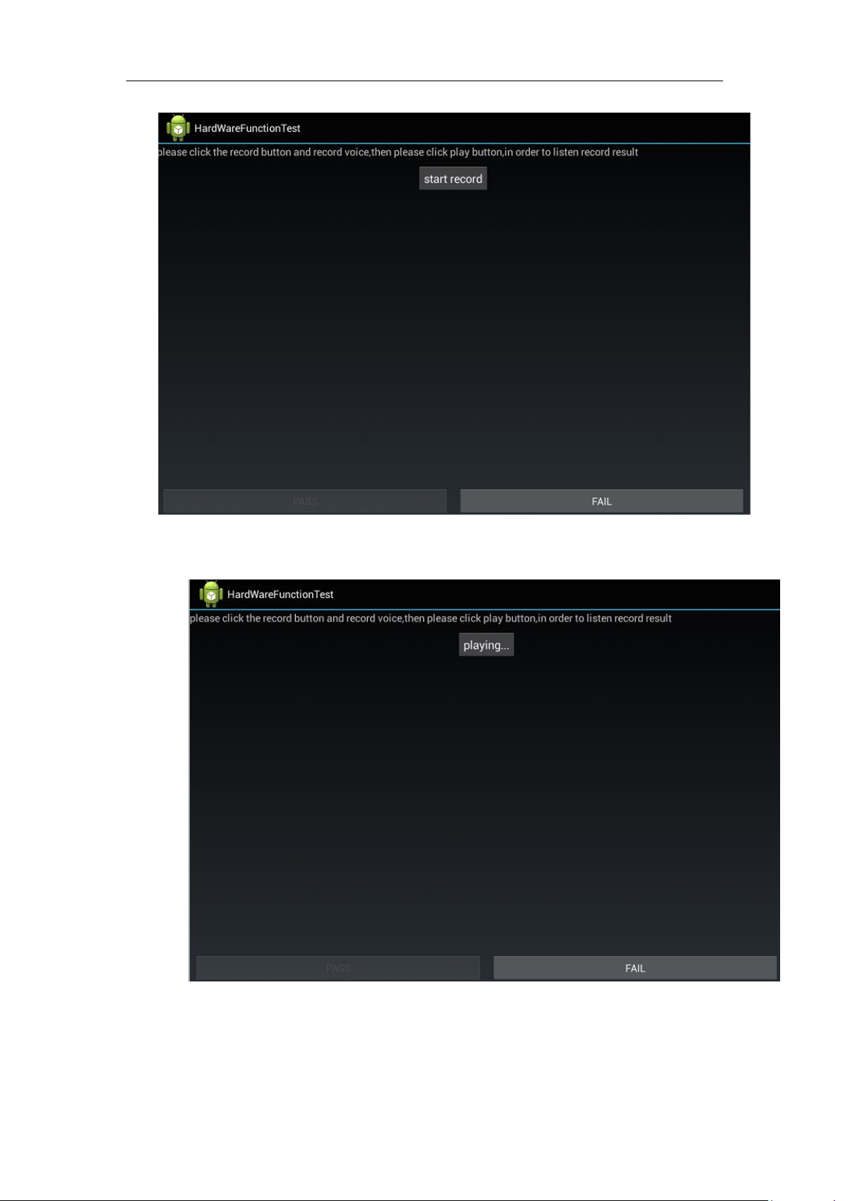
Figure 3.13(a)
58 / 66
Figure 3.13(b)
Green button means PASS, Red button means FAIL, as shown in figure 3.13(c) and 3.13(d).
Page 59
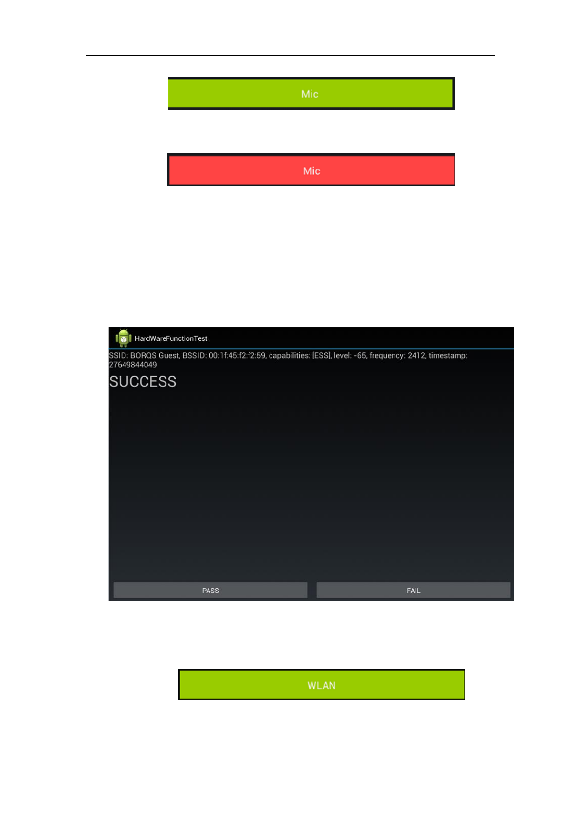
Figure 3.13(c)
Figure 3.13(d)
WLAN:
WLAN test, DUT will search AP, according to the test result which be displayed on the screen
please choose PASS or FAIL, as shown in figure 3.14(a).
59 / 66
Figure 3.14(a)
Green button means PASS, Red button means FAIL, as shown in figure 3.14(b) and 3.14(c).
Figure 3.14(b)
Page 60
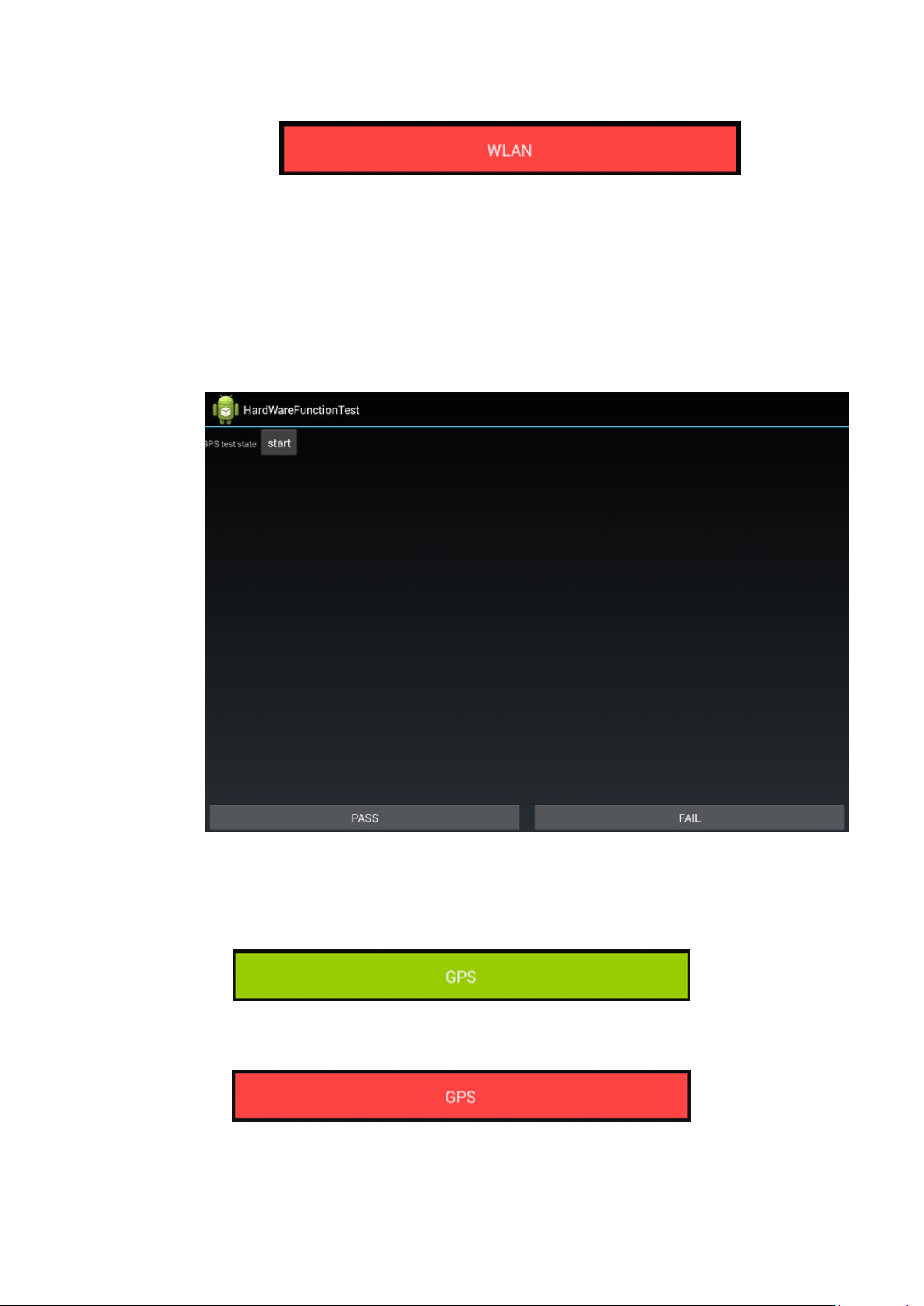
GPS:
GPS test, press “start” button and then according to the test result, please choose PASS or
FAIL, as shown in figure 3.15(a)
Figure 3.14(c)
60 / 66
Figure 3.15(a)
Green button means PASS, Red button means FAIL, as shown in figure 3.15(b) and 3.15(c).
Figure 3.15(b)
Figure 3.15(c)
Page 61
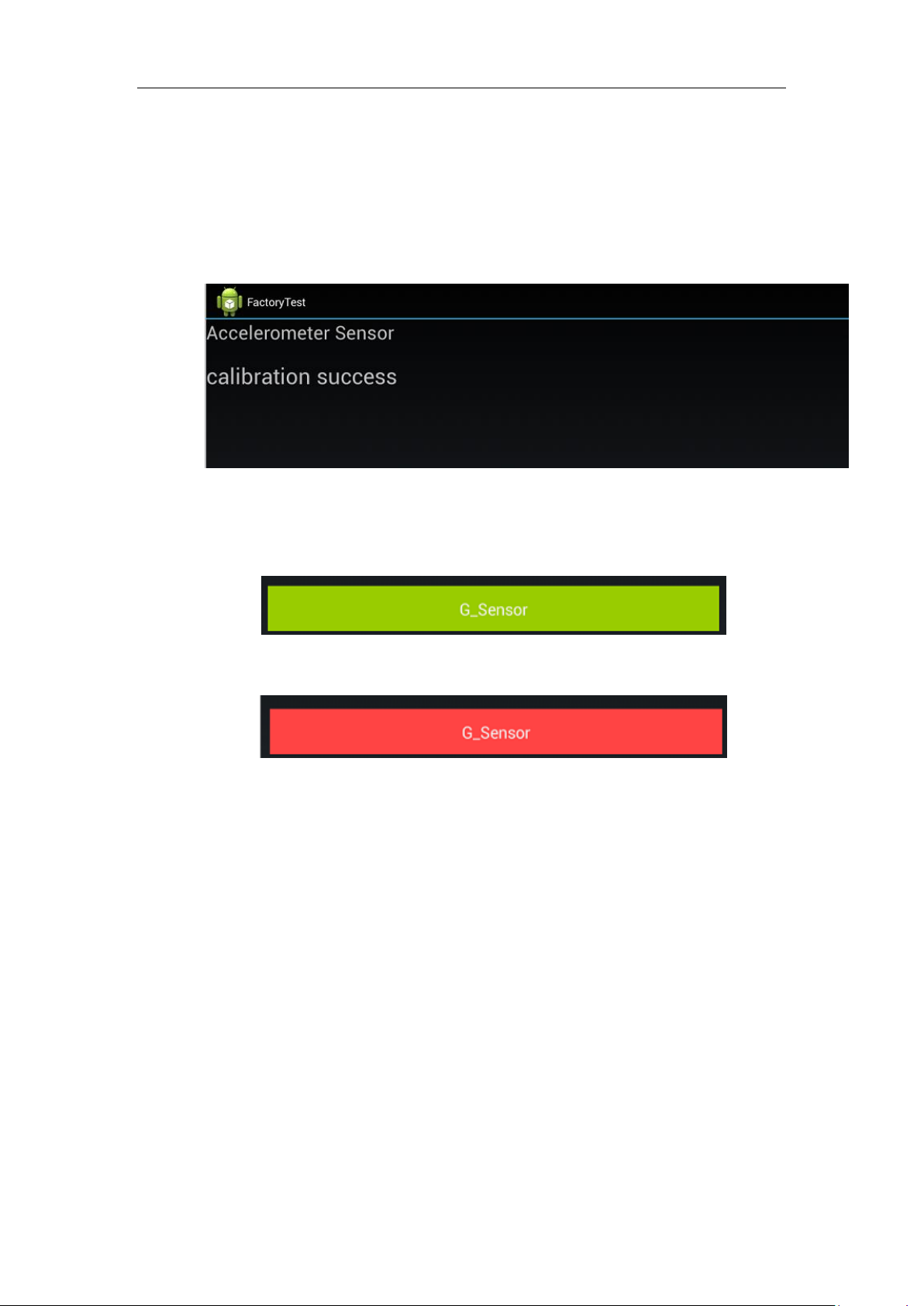
G_Sensor_Calibration
G_Sensor_Calibration test, It „s necessary to place the device horizontally firstly. And then
Choose “G_Sensor_Calibration”.
The test result will be shown on screen, according to the test result, please choose PASS or
FAIL,as shown in figure 3.16(a).
Green button means PASS, Red button means FAIL, as shown in figure 3.16(b) and 3.16(c).
Figure 3.16(a)
Figure 3.16(b)
Figure 3.16(c)
61 / 66
Page 62
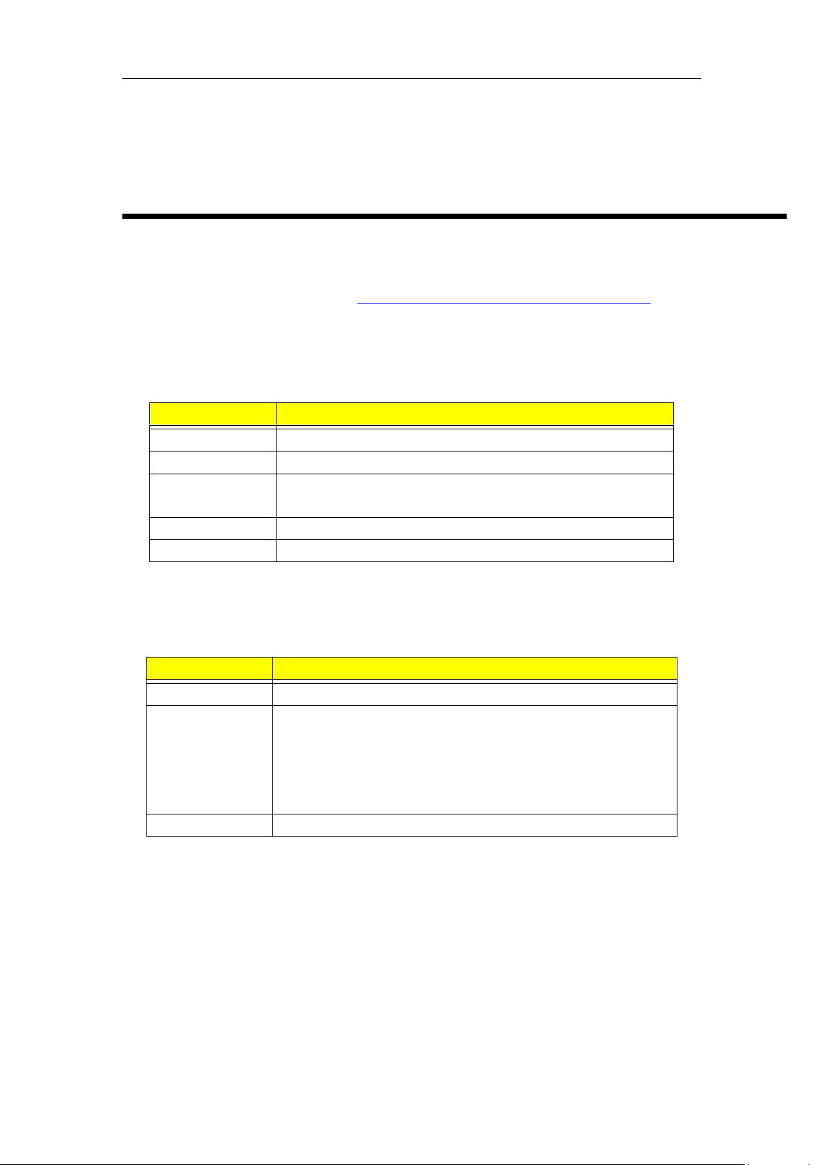
Code
Description
PPPPPPPPPP
Acer Part Number
YWW
3 digit numeric year and week code
SSSSS
5 character unique hexadecimal code by manufacturer base and
reset each week (0-9, A, B, C, D, E, F 16 code)
MM
Manufacturer code
VV
English version code
Code
Description
YWW
3 digit numeric year and week code (as above)
dddddd
6 unique decimal numbers derived from Acer 22 Code SN (SSSSS)
Transfer Rule: S1S2S3S4S5
dddddd = S1 * 164 + S2 * 163 + S3 * 162 + S4 * 161 + S5
Example: Acer FG SN (SSSSS) = 001FD,
SNID (dddddd) = 1 * 162 + 15 * 16 + 13 = 000509.
MM
Manufacturer code (as above)
CHAPTER5
Serial Number Definition
Acer 22 Barcode
Follows Code 128 standard – refer to http://www.adams1.com/pub/russadam/128code.html
Acer 22 Code SN
PPPPPPPPPPYWWSSSSSMMVV
Acer SNID
YWWddddddMM
62 / 66
Page 63
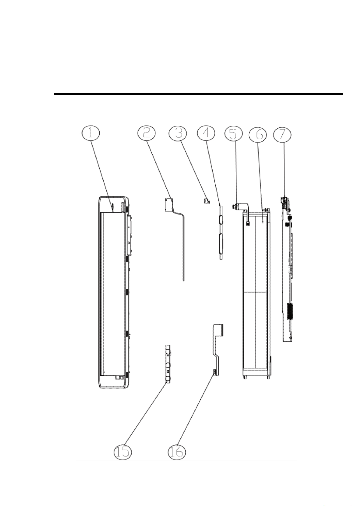
CHAPTER6
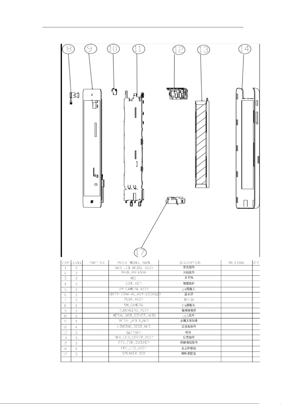
Exploded Diagram and Description
Ducati Exploded Diagram
63 / 66
Page 64
64 / 66
Page 65
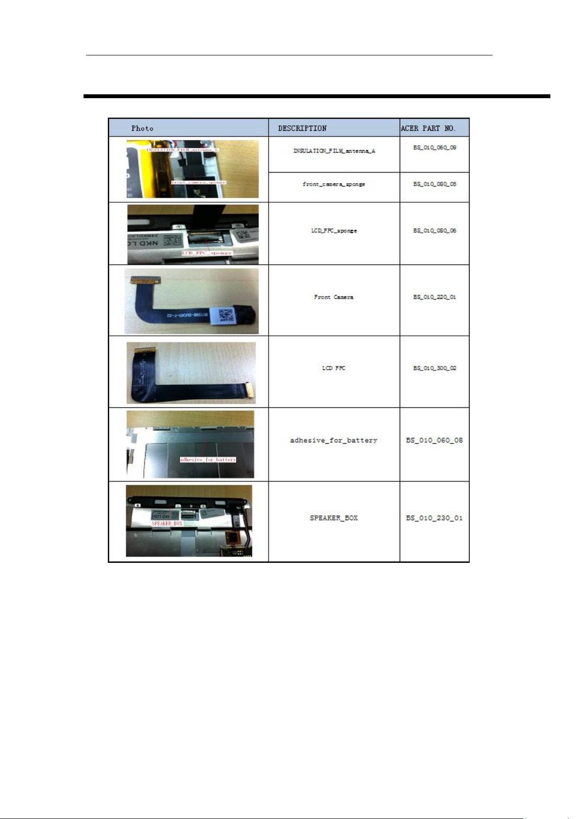
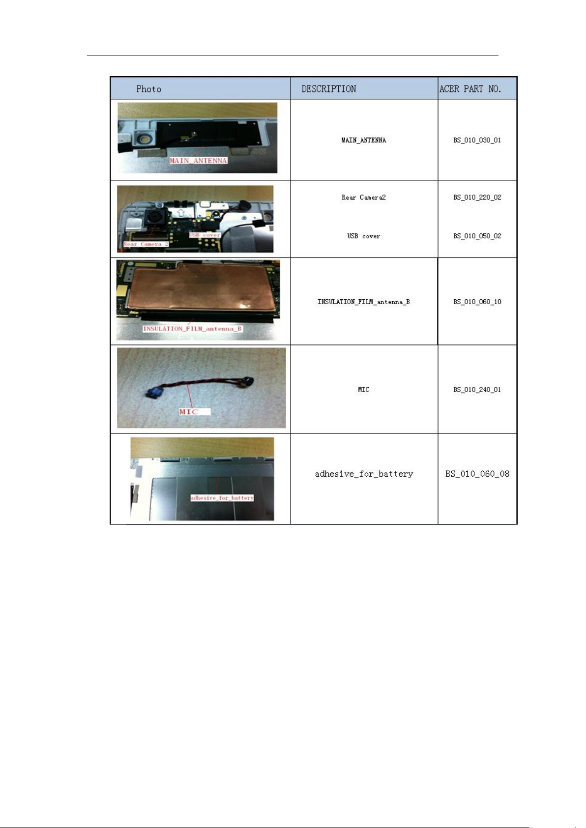
Spare Parts List
65 / 66
Page 66
66 / 66
 Loading...