

Page 1

TravelMate 8172/8172Z Series
Service Guide
Service guide files and updates are available
on the ACER/CSD web; for more information,
please refer to http://csd.acer.com.tw
PRINTED IN TAIWAN
Page 2

Revision History
Please refer to the table below for the updates made on TravelMate 8172/8172Z service guide.
Date Chapter Updates
2
Page 3

Copyright
Copyright © 2010 by Acer Incorporated. All rights reserved. No part of this publication may be reproduced,
transmitted, transcribed, stored in a retrieval system, or translated into any language or computer language, in
any form or by any means, electronic, mechanical, magnetic, optical, chemical, manual or otherwise, without
the prior written permission of Acer Incorporated.
Disclaimer
The information in this guide is subject to change without notice.
Acer Incorporated makes no representations or warranties, either expressed or implied, with respect to the
contents hereof and specifically disclaims any warranties of merchantability or fitness for any particular
purpose. Any Acer Incorporated software described in this manual is sold or licensed
programs prove defective following their purchase, the buyer (and not Acer Incorporated, its distributor, or its
dealer) assumes the entire cost of all necessary servicing, repair, and any incidental or consequential
damages resulting from any defect in the software.
“as is”. Should the
Acer is a registered trademark of Acer Corporation.
Intel is a registered trademark of Intel Corporation.
Pentium and Pentium II/III are trademarks of Intel Corporation.
Other brand and product names are trademarks and/or registered trademarks of their respective holders.
3
Page 4

Conventions
The following conventions are used in this manual:
SCREEN
MESSAGES
NOTE Gives bits and pieces of additional
WARNING Alerts you to any damage that might
CAUTION Gives precautionary measures to
IMPORTANT Reminds you to do specific actions
Denotes actual messages that appear
on screen.
information related to the current
topic.
result from doing or not doing specific
actions.
avoid possible hardware or software
problems.
relevant to the accomplishment of
procedures.
4
Page 5

Preface
Before using this information and the product it supports, please read the following general information.
1. This Service Guide provides you with all technical information relating to the BASIC CONFIGURATION
decided for Acer's “global” product offering. To better fit local market requirements and enhance product
competitiveness, your regional office MAY have decided to extend the functionality of a machine (e.g.
add-on card, modem, or extra memory capability). These LOCALIZED FEATURES will NOT be covered
in this generic service guide. In such cases, please contact your regional offices or the responsible
personnel/channel to provide you with further technical details.
2. Please note WHEN ORDERING FRU PARTS, that you should check the most up-to-date information
available on your regional web or channel. If, for whatever reason, a part number change is made, it will
not be noted in the printed Service Guide. For ACER-AUTHORIZED SERVICE PROVIDERS, your Acer
office may have a DIFFERENT part number code to those given in the FRU list of this printed Service
Guide. You MUST use the list provided by your regional Acer office to order FRU parts for repair and
service of customer machines.
5
Page 6

6
Page 7

Table of Contents
System Specifications 1
System Block Diagram . . . . . . . . . . . . . . . . . . . . . . . . . . . . . . . . . . . . . . . . . . . . . . . . .5
Board Layout . . . . . . . . . . . . . . . . . . . . . . . . . . . . . . . . . . . . . . . . . . . . . . . . . . . . . . . .6
Top View . . . . . . . . . . . . . . . . . . . . . . . . . . . . . . . . . . . . . . . . . . . . . . . . . . . . . . . .6
Bottom View . . . . . . . . . . . . . . . . . . . . . . . . . . . . . . . . . . . . . . . . . . . . . . . . . . . . .7
Your Acer Notebook tour . . . . . . . . . . . . . . . . . . . . . . . . . . . . . . . . . . . . . . . . . . . . . . .9
Top View . . . . . . . . . . . . . . . . . . . . . . . . . . . . . . . . . . . . . . . . . . . . . . . . . . . . . . . .9
Closed Front View . . . . . . . . . . . . . . . . . . . . . . . . . . . . . . . . . . . . . . . . . . . . . . . .10
Rear view . . . . . . . . . . . . . . . . . . . . . . . . . . . . . . . . . . . . . . . . . . . . . . . . . . . . . .10
Left View . . . . . . . . . . . . . . . . . . . . . . . . . . . . . . . . . . . . . . . . . . . . . . . . . . . . . . .11
Right View . . . . . . . . . . . . . . . . . . . . . . . . . . . . . . . . . . . . . . . . . . . . . . . . . . . . . .11
Base view . . . . . . . . . . . . . . . . . . . . . . . . . . . . . . . . . . . . . . . . . . . . . . . . . . . . . .12
Touchpad Basics (with fingerprint reader) . . . . . . . . . . . . . . . . . . . . . . . . . . . . .13
Touchpad basics (with two-click buttons) . . . . . . . . . . . . . . . . . . . . . . . . . . . . . .14
Using the Keyboard . . . . . . . . . . . . . . . . . . . . . . . . . . . . . . . . . . . . . . . . . . . . . . . . . .15
Lock Keys and embedded numeric keypad* . . . . . . . . . . . . . . . . . . . . . . . . . . . .15
Windows Keys . . . . . . . . . . . . . . . . . . . . . . . . . . . . . . . . . . . . . . . . . . . . . . . . . .16
Hot Keys . . . . . . . . . . . . . . . . . . . . . . . . . . . . . . . . . . . . . . . . . . . . . . . . . . . . . . .17
Using the system utilities . . . . . . . . . . . . . . . . . . . . . . . . . . . . . . . . . . . . . . . . . . . . . .18
Acer Backup Manager . . . . . . . . . . . . . . . . . . . . . . . . . . . . . . . . . . . . . . . . . . . .20
Power management . . . . . . . . . . . . . . . . . . . . . . . . . . . . . . . . . . . . . . . . . . . . . .21
Acer PowerSmart key . . . . . . . . . . . . . . . . . . . . . . . . . . . . . . . . . . . . . . . . . . . . .21
Acer eRecovery Management . . . . . . . . . . . . . . . . . . . . . . . . . . . . . . . . . . . . . .21
Burn backup discs . . . . . . . . . . . . . . . . . . . . . . . . . . . . . . . . . . . . . . . . . . . . . . . .22
Restore . . . . . . . . . . . . . . . . . . . . . . . . . . . . . . . . . . . . . . . . . . . . . . . . . . . . . . . .22
Hardware Specifications and Configurations . . . . . . . . . . . . . . . . . . . . . . . . . . . . . . .24
BIOS Setup Utility . . . . . . . . . . . . . . . . . . . . . . . . . . . . . . . . . . . . . . . . . . . . . . . . . . . .29
System Utilities 29
Invoking BIOS Setup . . . . . . . . . . . . . . . . . . . . . . . . . . . . . . . . . . . . . . . . . . . . . . . . .30
Information . . . . . . . . . . . . . . . . . . . . . . . . . . . . . . . . . . . . . . . . . . . . . . . . . . . . .30
Main . . . . . . . . . . . . . . . . . . . . . . . . . . . . . . . . . . . . . . . . . . . . . . . . . . . . . . . . . .31
Security . . . . . . . . . . . . . . . . . . . . . . . . . . . . . . . . . . . . . . . . . . . . . . . . . . . . . . . .33
Boot . . . . . . . . . . . . . . . . . . . . . . . . . . . . . . . . . . . . . . . . . . . . . . . . . . . . . . . . . . .36
Exit . . . . . . . . . . . . . . . . . . . . . . . . . . . . . . . . . . . . . . . . . . . . . . . . . . . . . . . . . . .36
BIOS Flash Utility . . . . . . . . . . . . . . . . . . . . . . . . . . . . . . . . . . . . . . . . . . . . . . . . . . . .39
DOS flash BIOS SOP . . . . . . . . . . . . . . . . . . . . . . . . . . . . . . . . . . . . . . . . . . . . . . . . .40
Clean BIOS Password SOP . . . . . . . . . . . . . . . . . . . . . . . . . . . . . . . . . . . . . . . . . . . .43
Clean HDD Password SOP . . . . . . . . . . . . . . . . . . . . . . . . . . . . . . . . . . . . . . . . . . . .48
Crisis Disk SOP . . . . . . . . . . . . . . . . . . . . . . . . . . . . . . . . . . . . . . . . . . . . . . . . . . . . .54
DMI Utility SOP . . . . . . . . . . . . . . . . . . . . . . . . . . . . . . . . . . . . . . . . . . . . . . . . . . . . . .57
LAN EEPROM Utility SOP . . . . . . . . . . . . . . . . . . . . . . . . . . . . . . . . . . . . . . . . . . . . .61
Winflash SOP . . . . . . . . . . . . . . . . . . . . . . . . . . . . . . . . . . . . . . . . . . . . . . . . . . . . . . .65
Disassembly Requirements . . . . . . . . . . . . . . . . . . . . . . . . . . . . . . . . . . . . . . . .69
Related Information . . . . . . . . . . . . . . . . . . . . . . . . . . . . . . . . . . . . . . . . . . . . . . .69
Replacement Requirements . . . . . . . . . . . . . . . . . . . . . . . . . . . . . . . . . . . . . . . .69
. . . . . . . . . . . . . . . . . . . . . . . . . . . . . . . . . . . . . . . . . . . . . . . . . . . . . . . . . . . . . .69
Machine Disassembly and Replacement 69
Pre-disassembly Instructions . . . . . . . . . . . . . . . . . . . . . . . . . . . . . . . . . . . . . . .70
Disassemble Process . . . . . . . . . . . . . . . . . . . . . . . . . . . . . . . . . . . . . . . . . . . . .71
External Module Disassembly Process . . . . . . . . . . . . . . . . . . . . . . . . . . . . . . . .71
Removing the Battery Pack . . . . . . . . . . . . . . . . . . . . . . . . . . . . . . . . . . . . . . . .72
Removing the HDD. . . . . . . . . . . . . . . . . . . . . . . . . . . . . . . . . . . . . . . . . . . . . . .74
1
Page 8

Table of Contents
Removing the DIMM module . . . . . . . . . . . . . . . . . . . . . . . . . . . . . . . . . . . . . . .78
Remove the Wireless module . . . . . . . . . . . . . . . . . . . . . . . . . . . . . . . . . . . . . . .81
LCD Module Disassembly Process . . . . . . . . . . . . . . . . . . . . . . . . . . . . . . . . . . .83
Removing the keyboard . . . . . . . . . . . . . . . . . . . . . . . . . . . . . . . . . . . . . . . . . . .84
Removing the Upper Case . . . . . . . . . . . . . . . . . . . . . . . . . . . . . . . . . . . . . . . . .87
Removing the LCD Module . . . . . . . . . . . . . . . . . . . . . . . . . . . . . . . . . . . . . . . . .91
Removing the Bluetooth Module . . . . . . . . . . . . . . . . . . . . . . . . . . . . . . . . . . . . .98
Removing the Mainboard . . . . . . . . . . . . . . . . . . . . . . . . . . . . . . . . . . . . . . . . .100
LCD Module Disassembly Process . . . . . . . . . . . . . . . . . . . . . . . . . . . . . . . . . .113
Removing the Mainboard . . . . . . . . . . . . . . . . . . . . . . . . . . . . . . . . . . . . . . . . .114
Removing the Camera Board . . . . . . . . . . . . . . . . . . . . . . . . . . . . . . . . . . . . . .118
Remove the Antennas . . . . . . . . . . . . . . . . . . . . . . . . . . . . . . . . . . . . . . . . . . .119
LCD Reassembly . . . . . . . . . . . . . . . . . . . . . . . . . . . . . . . . . . . . . . . . . . . . . . . . . . .124
Replacing the Antenna . . . . . . . . . . . . . . . . . . . . . . . . . . . . . . . . . . . . . . . . . . .124
Replacing the Camera Board . . . . . . . . . . . . . . . . . . . . . . . . . . . . . . . . . . . . . .128
Replace the Wireless LAN Module . . . . . . . . . . . . . . . . . . . . . . . . . . . . . . . . . .129
Replacing LCM Module . . . . . . . . . . . . . . . . . . . . . . . . . . . . . . . . . . . . . . . . . . .130
Replacing the Mainboard . . . . . . . . . . . . . . . . . . . . . . . . . . . . . . . . . . . . . . . . .135
Replacing the Panel . . . . . . . . . . . . . . . . . . . . . . . . . . . . . . . . . . . . . . . . . . . . .144
Replacing the Bluetooth Module . . . . . . . . . . . . . . . . . . . . . . . . . . . . . . . . . . . .151
Replacing the Upper Case . . . . . . . . . . . . . . . . . . . . . . . . . . . . . . . . . . . . . . . .152
Replacing the keyboard . . . . . . . . . . . . . . . . . . . . . . . . . . . . . . . . . . . . . . . . . .156
Replace the Wireless LAN Module . . . . . . . . . . . . . . . . . . . . . . . . . . . . . . . . . .158
Replace the DIMM module . . . . . . . . . . . . . . . . . . . . . . . . . . . . . . . . . . . . . . . .159
Replacing HDD module . . . . . . . . . . . . . . . . . . . . . . . . . . . . . . . . . . . . . . . . . .162
Replacing the battery . . . . . . . . . . . . . . . . . . . . . . . . . . . . . . . . . . . . . . . . . . . .164
Troubleshooting 165
System Check Procedures . . . . . . . . . . . . . . . . . . . . . . . . . . . . . . . . . . . . . . . . . . . .166
External Diskette Drive Check . . . . . . . . . . . . . . . . . . . . . . . . . . . . . . . . . . . . .166
External CD-ROM Drive Check . . . . . . . . . . . . . . . . . . . . . . . . . . . . . . . . . . . .166
Keyboard or Auxiliary Input Device Check . . . . . . . . . . . . . . . . . . . . . . . . . . . .166
Memory check . . . . . . . . . . . . . . . . . . . . . . . . . . . . . . . . . . . . . . . . . . . . . . . . . .167
Power System Check . . . . . . . . . . . . . . . . . . . . . . . . . . . . . . . . . . . . . . . . . . . .167
Touchpad Check . . . . . . . . . . . . . . . . . . . . . . . . . . . . . . . . . . . . . . . . . . . . . . . .168
Power-On Self-Test (POST) Error Message . . . . . . . . . . . . . . . . . . . . . . . . . . . . . .169
Index of Error Messages . . . . . . . . . . . . . . . . . . . . . . . . . . . . . . . . . . . . . . . . . . . . . .170
InsydeH2O BIOS Beep Codes . . . . . . . . . . . . . . . . . . . . . . . . . . . . . . . . . . . . . . . . .173
Index of Symptom-to-FRU Error Message . . . . . . . . . . . . . . . . . . . . . . . . . . . . . . . .177
Intermittent Problems . . . . . . . . . . . . . . . . . . . . . . . . . . . . . . . . . . . . . . . . . . . . . . . .181
Undetermined Problems . . . . . . . . . . . . . . . . . . . . . . . . . . . . . . . . . . . . . . . . . . . . . .182
Jumper and Connector Locations 183
Top View . . . . . . . . . . . . . . . . . . . . . . . . . . . . . . . . . . . . . . . . . . . . . . . . . . . . . . . . . .183
Bottom View. . . . . . . . . . . . . . . . . . . . . . . . . . . . . . . . . . . . . . . . . . . . . . . . . . . . . . . .184
FRU (Field Replaceable Unit) List 187
TravelMate 8172/8172Z Exploded Diagram . . . . . . . . . . . . . . . . . . . . . . . . . . . . . . .188
TravelMate 8172/8172Z FRU List . . . . . . . . . . . . . . . . . . . . . . . . . . . . . . . . . . . . . . .191
Model Definition and Configuration 203
Test Compatible Components 223
Online Support Information 231
2
Page 9

Chapter 1
System Specifications
Features
Below is a brief summary of the computer’s many features:
Operating system
Genuine Windows® 7 Professional 32-bit
Genuine Windows
CPU and chipset
Intel® Core™ i5-430UM/i5-520UM/i5-540UM processor (3 MB L3 cache, 1.20/1.06/1.20 GHz with Turbo
Boost up to 1.73/1.86/2 GHz, DDR3 800 MHz, 18 W), supporting Intel
Cache
®
7 Home Premium 64-bit
®
64 architecture, Intel® Smart
Intel® Core™ i3-330UM processor (3 MB L3 cache, 1.20 GHz, DDR3 800 MHz, 18 W), supporting Intel®
64 architecture, Intel
Mobile Intel
®
HM55 Express Chipse (for TM8172Z)
®
Smart Cache
Memory
Dual-channel DDR3 SDRAM support:
z Up to 2 GB of DDR3 system memory, upgradable to 4 GB using two soDIMM modules
Display and graphics
11.6" HD 1366 x 768 (WXGA) pixel resolution, high-brightness (200-nit) LED-backlit TFT LCD
Mercury-free environment friendly
Intel® HD Graphics with 128 MB of dedicated system memory, supporting Microsoft® DirectX® 10
Dual independent display support
16.7 million colors
External resolution / refresh rate:
z VGA port up to 2560 x 1600 : 60 Hz
MPEG-2/DVD decoding
WMV9 (VC-1) and H.264 (AVC) decoding
Storage subsystem
Hard disk drive:
z 160/250/320/500/640 GB or larger
Multi-in-1 card reader, supporting:
z Secure Digital™ (SD) Card, MultiMediaCard™(MMC), Memory Stick™ (MS), Memory Stick
PRO™(MS PRO), xD-Picture Card™(xD)
z Supported 8GB (test pass)
Chapter 1 1
Page 10

Dimensions and weight
Dimensions:
z 285 (W) x 206.3 (D) x 20.2/29.1 (H) mm (11.22 x 8.12 x 0.795/ 1.146 inches)
Weight:
z 1.35 kg (2.97 lbs.) with 6-cell battery pack (non-3G model)
Power adapter and battery
ACPI 3.0 CPU power management standard: supports Standby and Hibernation power-saving modes
Power adapter:2-pin 40 W Acer MiniGo AC adapter
z 93.2 (W) x 32.2 (D) x 42.5 (H) mm (3.66 x 1.26 x 1.67 inches)
z 180 g (0.39 lbs.) with 250 cm DC cable
z 210 g (0.47 lbs.) with 250 cm DC cable and one AC power plug
Battery
24 W 2200 mAh 3-cell Li-ion battery pack
Battery life: 3 hours
48 W 4400 mAh 6-cell Li-ion battery pack
Battery life: 6 hours
63 W 5600 mAh 6-cell Li-ion battery pack
Battery life: 8 hours
ENERGY STAR
®
Input and control
Keyboar
z 84-/85-/88-key full-size Acer FineTip keyboard with international language support
Touchpad
z Multi-gesture touchpad, supporting two-finger scroll, pinch, rotate, flip
Control key
z Acer Bio-Protection fingerprint reader
Audio
Two built-in stereo speakers
High-definition audio support
MS-Sound compatible
Built-in microphone
Webcam
Acer Video Conference, featuring:
z Acer Crystal Eye webcam with 1280 x 1024 resolution
z Acer Video Conference Manager software, featuring Video Quality Enhancement (VQE) technology,
supporting 640 x 480 resolution online video calls
Wireless and networking
WLAN:
z Acer InviLink™ Nplify™ 802.11b/g/n Wi-Fi CERTIFIED™
z Acer InviLink™ 802.11b/g Wi-Fi CERTIFIED™
z Supporting Acer SignalUp™wireless technology
2 Chapter 1
Page 11

WPAN: BluetoothR 3.0+HS
WWAN: UMTS/HSPA at 900/2100 MHz and quad-band GSM/GPRS/EDGE at 850/900/1800/1900 MHz,
upgradable to 7.2 Mb/s HSDPA and 5.7 Mb/s HSUPA (for 3G model)
LAN: Gigabit Ethernet, Wake-on-LAN ready
Input and output
Acer Easyport IV connector
Multi-in-1 card reader (SD, MMC, MS, MS PRO, xD)
Three USB 2.0 ports
External display (VGA) port
Headphone/speaker/line-out jack
Microphone-in jack
Ethernet (RJ-45) port
DC-in jack for AC adapter
Security
Acer Bio-Protection fingerprint solution, featuring Pre-Boot Authentication (PBA), computer protection,
Acer FingerLaunch
BIOS user, supervisor, HDD passwords
Kensington lock slot
Software
Productivity
z Acer ePower Management
z Acer eRecovery Management
z Adobe
z Adobe
z eSobi™
z Google Toolbar™
z Microsoft
z Microsoft
z Norton™ Online Backup
Security
z Acer Bio-Protection
z McAfee® Internet Security Suite Trial
InstantOn
z Instant View
Multimedia
z Corel
Communication and ISP
z Acer Crystal Eye
z Acer Video Conference Manager
z Microsoft® Silverlight™
z Skype™
z Windows Live™ Essentials-Wave 3.2 (Mail, Photo Gallery, Live™ Messenger, Movie Maker, Writer)
®
®
®
WinDVD
Flash® Player 10
Reader® 9.1
®
Office Personal 2007 (Service Pack 2)(Japan only, subject to customer request)
®
Office Ready (Service Pack 2)
Chapter 1 3
Page 12

Web links and utilities
z Acer Accessory Store (Belgium, France, Germany, Italy, Netherlands, Spain, Sweden, UK only)
z Acer Identity Card
z Acer Registration
z Acer Updater
z eBay
z Netflix shortcut (US only)
®
shortcut 2009 (Canada, France, Germany, Italy, Mexico, Spain, UK, US only)
Options and accessories
1 GB / 2 GB / DDR3 1066 MHz soDIMM module
6-cell Li-ion battery pack
3-pin 30 W AC adapter
External USB HDD
External USB optical disc drive
Acer Easyport IV
System compliance
Wi-Fi
ACPI 3.0
Mobile PC 2002
DMI 2.0
®
Warranty
One-year International Travelers Warranty (ITW)
Quality and reliability tests
Temperature and humidity
Hinge life
Weight and pressure
Acoustics
Spillage
Free drop
Shock and vibration
Electrostatic discharge immunity
Keyboard-switch life
MTBF (mean time between failures)
4 Chapter 1
Page 13
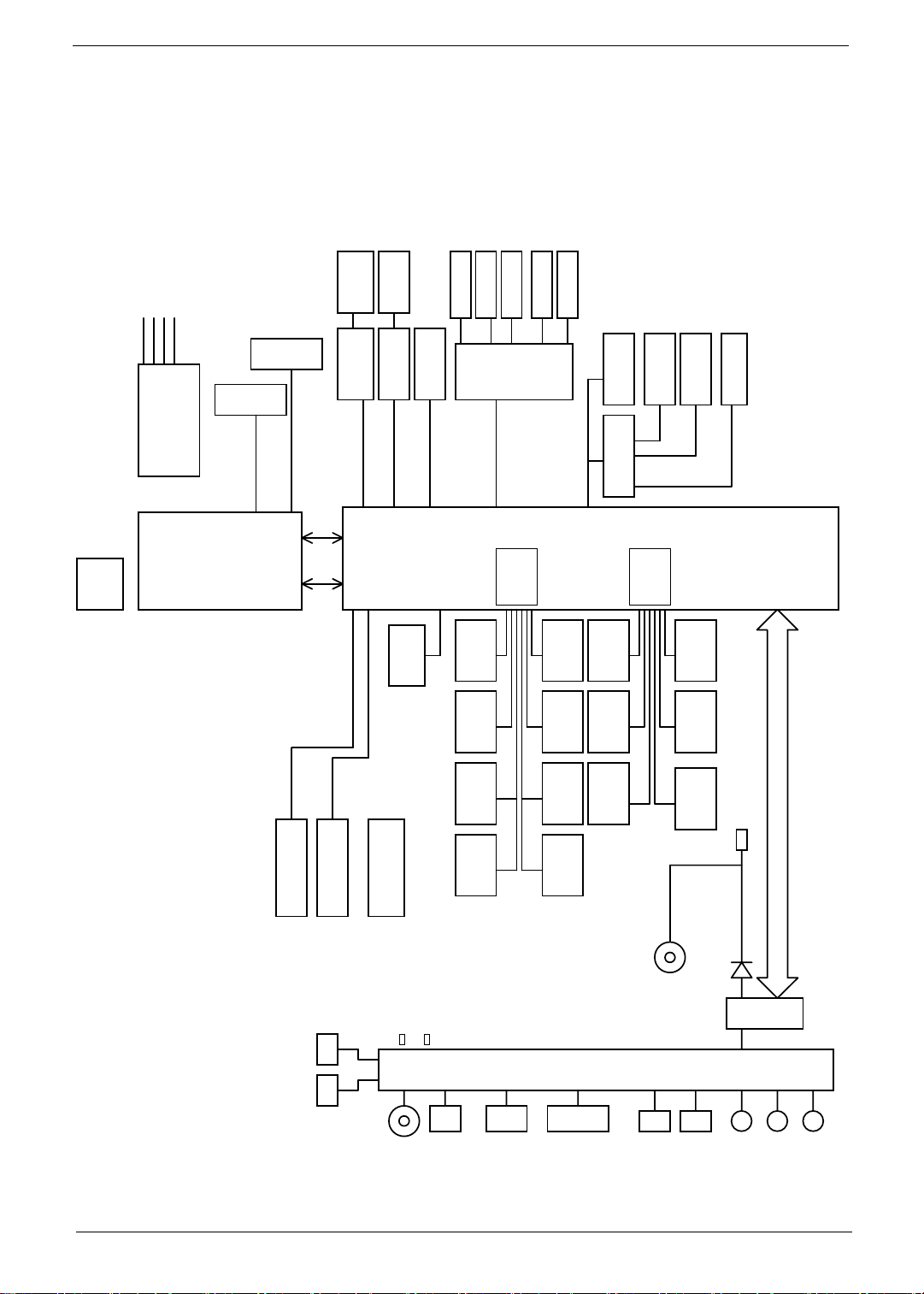
System Block Diagram
y3y2y2
y2
GBO
Q/27
244NI{,0.
211NI{,0.
59NI{
38NI{0:7NI{,0.
Q/37
DML`HFO
JDT:MST42:8BLMGU
!BSSBOEBMF
TPEJNN1
DQV,HNDI
CHB-2399Q
TPEJNN2
EES4!2/6W
!91102177!NI{
45ny39nn
Q/38
EES4!2/6W
!91102177!NI{
Q/27.2:
Q/38
ENJ!y5
GEJ
Q/41
SK56
Q/41
HcF
NjojDbse!
CDN68871
QDJ.Fyqsftt!y2!3/6HI{
QDJ.Fyqsftt!y2!3/6HI{
Jcfyqfbl.N
SHC
MWET
Q/43
TJN!Tmpu
Q/43
VNUT
QL u$5
IN66
Q/44
IEE
Q/42
TQL
Pvu
Q/43
XMBO
Qpsu$4
NjojDbse!
QDJ.Fyqsftt!y2!3/6HI{
nCHB!2182qjo
TBUB!261
VTC1VTC2VTC3VTC4
Q/42
JouNjd
JO
IEB!35NI{
Q/3:Q/3:Q/3:
Qpsu1
Qpsu2Qpsu3
Tufsfp
Bvejp
Q/42
Bobmph!Jo
JO
Dpefd
2$JDIF2/201/3!CTV
Tvqqpsu
T1T4!tubuf
Q/42
Bobmph!Pvu
Pvu
Pvu
Q/42
DY31783
VTC5VTC6VTC7VTC8
DbseSfbefs Epdljoh
Q/42
TQEJG
MQD!4/4W!44NI{
Q/47
VTC9VTC21
Q/45
VTC:
Q/43
91Qpsu
Q/46
UF9613F
QNV'LCD
FIDJ$3
Q/43Q/44
TJN
Q/39
DbnfsbCmvfuppui
LC
Tvqqpsu
T1T4!tubuf
Q/46
VTC22
VTC23
Q/44
Tujdl!Qpjou
Hmjef!Qbe
Q/44
GjohfsQsjou
Q/43
XMBO
Gmbti
TQJ
Q/46
SPN
Q/31.36
38nny36nn
VTC!3/102/2
VTC!3/102/2
VTC24
Q/43
VNUT
M7
MDE
Q/39
DSU
Q/39
VTC!3/102/2
Q/44
IBMM!TXJUDI
EPDL`BEQJO
E48
BEJO
Qpxfs!po!MFE
DSU!jo!MFE
Q/47
Fbtz!Qpsu!Dbcmf!Dpo
VTC
VTC
VTC
VTC
BEJO
SK56
DSU
EWJ
IQ
NJD
MJOF!JO
Chapter 1 5
Fbtz!Qpsu
Page 14
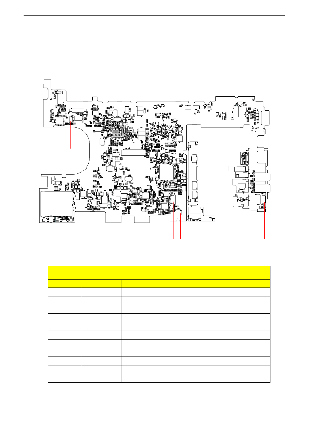
Board Layout
Top View
1
3
4
25
9
No. Name Description
6
TravelMate 8172/8172Z M/B layout and connector location
TOP view
8
11
1 CN1 LCM connector
2 CN2 Power
3 CN4 Keyboard connector
4 CN5 Microphone connector
5 CN6 Touch pad connector
6 CN7 Audio cable connector 1
7 CN8 Audio cable connector 2
8 CN9 Card reader slot
9 CN10 Bluetooth connector
10 CN11 Speaker connector
11 CN31 Webcam connector
710
6 Chapter 1
Page 15
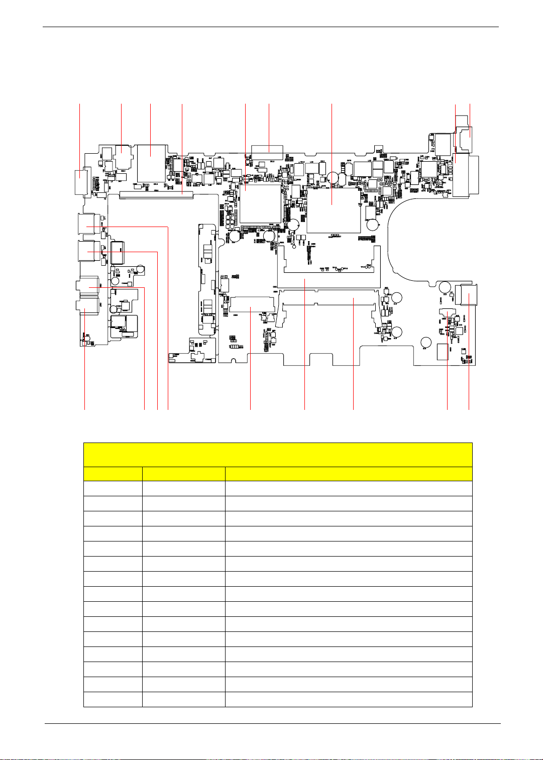
Bottom View
17
28
1614
18
13
1215 29
27
No. Name Description
22
1920
TravelMate 8172/8172Z M/B layout and connector location
26
Bottom view
21
12 CN12 LAN slot
13 CN13 Battery connector
14 CN14 DC-in jack
15 CN15 EZ-Docking slot
16 CN16 SIM Card slot
17 CN17 VGA port
18 CN18 HDD connector
19 CN18 USB slot 1
20 CN20 USB slot 2
21 CN21 DIMM-0
22 CN22 MIC jack
23 CN23 Fan connector
24 CN24 USB slot-3
25 CN25 DIMM-1
26 CN26 3G card slot
25
23 24
Chapter 1 7
Page 16

TravelMate 8172/8172Z M/B layout and connector location
Bottom view
No. Name Description
27 CN27 Earphone connector
28 U30 South bridge
29 U32 CPU+ North bridge
8 Chapter 1
Page 17
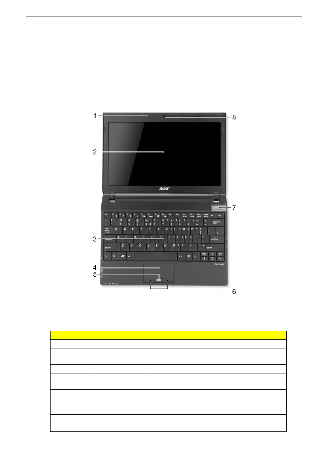
Your Acer Notebook tour
After setting up your computer as illustrated in the Just for Starters... poster, let us show you around your new
Acer notebook.
Top View
No. Icon Item Description
1 Microphones Stereo internal microphones for sound recording.
2 Display screen Also called Liquid-Crystal Display (LCD),displays
computer output (Configuration may vary by models).
3 Keyboard For entering data into your computer.
4 Touchpad Touch-sensitive pointing device which functions like a
computer mouse.
5Acer Bio-
Protection
fingerprint reader
6 Click buttons
(left and right)
Chapter 1 9
The center button serves as the Acer Bio-Protection
fingerprint reader, supporting Pre-Boot Authentication
(PBA) computer protection, Acer FingerLaunch.
The left and right buttons function like the left and right
mouse buttons.
Page 18
No. Icon Item Description
7 Power switch Turns the computer on and off.
8 Acer Crystal Eye
webcam
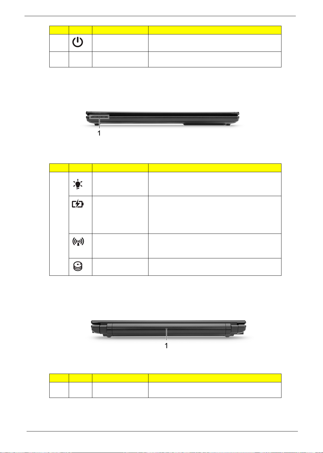
Closed Front View
No. Icon Item Description
1 Power indicator Indicates the computer's power status.
Battery indicator Indicates the computer's battery status.
Communication
indicator
Web camera for video communication.
1. Charging: The light shows amber when the battery
is charging.
2. Fully charged: The light shows blue when in AC
mode.
Indicates the computer’s wireless connectivity device
status.
Rear view
No. Icon Item Description
1 Battery Provides power for the computer to be used while
HDD indicator Indicates when the hard disk drive is active.
unplugged.
10 Chapter 1
Page 19
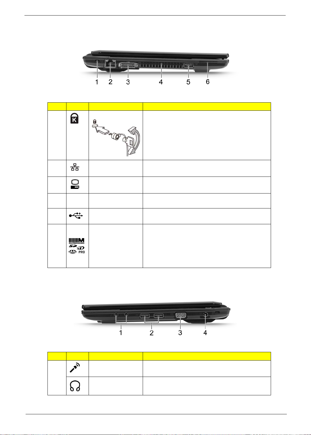
Left View
No. Icon Item Description
1 Kensington lock slot Connects to a Kensington-compatible computer
2 Ethernet (RJ-45) port Connects to an Ethernet 10/100/1000- based
security lock.
NOTE: Wrap the computer security lock cable around
an immovable object such as a table or handle of a
locked drawer. Insert the lock into the notch and turn
the key to secure the lock. Some keyless models are
also available.
network.
3 Acer EasyPort
4 Ventilation slots Enable the computer to stay cool,even after
5 USB 2.0 ports Connect to USB 2.0 devices (e.g., USB mouse, USB
6Multi-in-1
Right View
connector
card reader
Connects to Acer EasyPort.
prolonged use.
camera).
Accepts Secure Digital (SD),MultiMediaCard (MMC),
Memory Stick (MS), Memory Stick PRO (MS PRO),
xD-Picture Card (xD).
NOTE: Push to remove/install the card. Only one card
can operate at any given time.
No. Icon Item Description
1 Microphone-in jack Accepts inputs from external microphones.
Headphones/
speaker/line-out jack
Chapter 1 11
Connects to audio line-out devices (e.g., speakers,
headphones).
Page 20
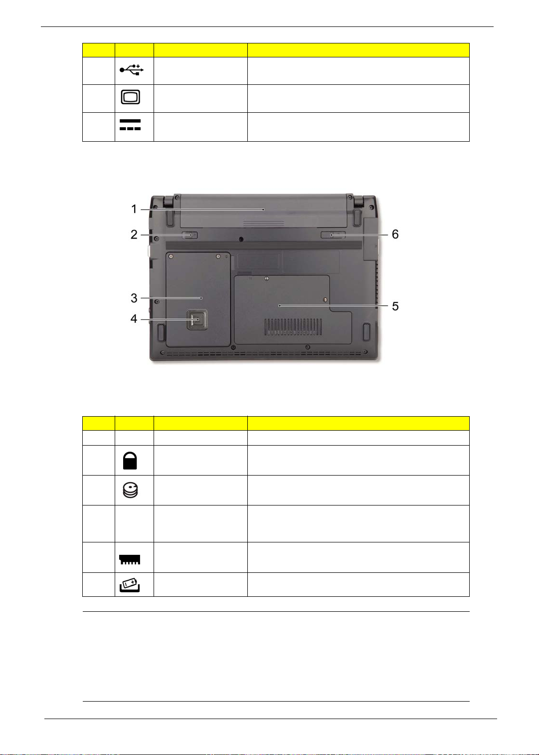
No. Icon Item Description
2 USB 2.0 port Connects to USB 2.0 devices (e.g., USB mouse, USB
3 External display
4 DC-in jack Connects to an AC adapter.
Base view
(VGA) port
camera).
Connects to a display device (e.g., external monitor,
LCD projector).
No. Icon Item Description
1 Battery bay Houses the computer's battery pack.
2 Battery lock Locks the battery in position.
3 Hard disk bay Houses the computer's hard disk (secured with
screws).
4 Acer DASP (Disk
Anti-Shock
Protection)
5 Memory
compartment
6 Battery release latch Releases the battery for removal.
Environment Temperature:
z Operating: 5°C to 35°C
z Non-operating: -20°C to 65°C
Humidity (non-condensing):
z Operating: 20% to 80%
z Non-operating: 20% to 80%
Protects the hard disk from shocks and bumps.
Houses the computer's main memory.
12 Chapter 1
Page 21
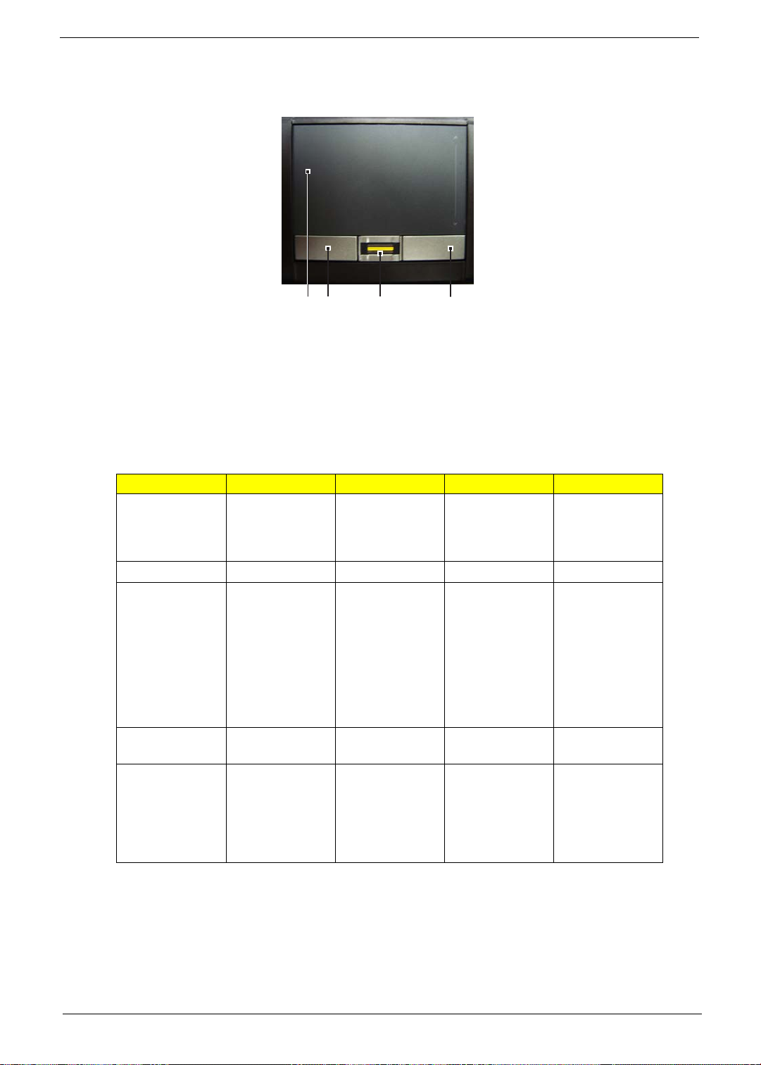
Touchpad Basics (with fingerprint reader)
The following items show you how to use the touchpad with Acer Bio-Protection fingerprint reader.
1 23 4
Move your finger across the touchpad (1) to move the cursor.
Press the left (2) and right (4) buttons located beneath the touchpad to perform selection and execution
functions. These two buttons are similar to the left and right buttons on a mouse. Tapping on the
touchpad is the same as clicking the left button.
Use Acer Bio-Protection fingerprint reader (3) supporting Acer FingerNav 4-way control function (only
for certain models) to scroll up or down and move left or right a page. This fingerprint reader or button
mimics your cursor pressing on the right scroll bar of Windows applications.
Function Left Button (2) Right Button (4) Main touchpad (1) Center button (3)
Execute Quickly click
twice.
Select Click once. Tap once.
Drag Click and hold,
then use finger
on the touchpad
to drag the
cursor.
Access context
menu
Scroll Swipe up/down/
Click once.
Tap twice (at the
same speed as
double-clicking a
mouse button).
Tap twice (at the
same speed as
double-clicking a
mouse button);
rest your finger
on the touchpad
on the second
tap and drag the
cursor.
left/right using
Acer FingerNav
4-way control
function(Manufacturing option).
Chapter 1 13
Page 22

Touchpad basics (with two-click buttons)
The following items show you how to use the touchpad with two-click buttons.
Move your finger across the touchpad to move the cursor.
Press the left and right buttons located beneath the touchpad to perform selection and execution
functions. These two buttons are similar to the left and right buttons on a mouse. Tapping on the
touchpad is the same as clicking the left button.
Function Left Button Right Button Main touchpad
Execute Quickly click twice. Tap twice (at the
same speed as
double-clicking a
mouse button).
Select Click once. Tap once.
Drag Click and hold, then
use finger on the
touchpad to drag the
cursor.
Access context menu Click once.
NOTE: Illustrations for reference only. The exact configuration of your PC depends on the model purchased.
Tap twice (at the
same speed as
double-clicking a
mouse button); rest
your finger on the
touchpad on the
second tap and drag
the cursor.
NOTE: When using the touchpad, keep it
finger movement; hence, the lighter the touch, the better the response. Tapping harder will not
increase the touchpad's responsiveness.
NOTE: By default, vertical and horizontal scrolling is enabled on your touchpad. It can be disabled under
Mouse settings in Windows Control Panel.
— and your fingers — dry and clean. The touchpad is sensitive to
14 Chapter 1
Page 23
Using the Keyboard
The keyboard has full-sized keys and an embedded numeric keypad*, separate cursor, lock, Windows,
function and special keys.
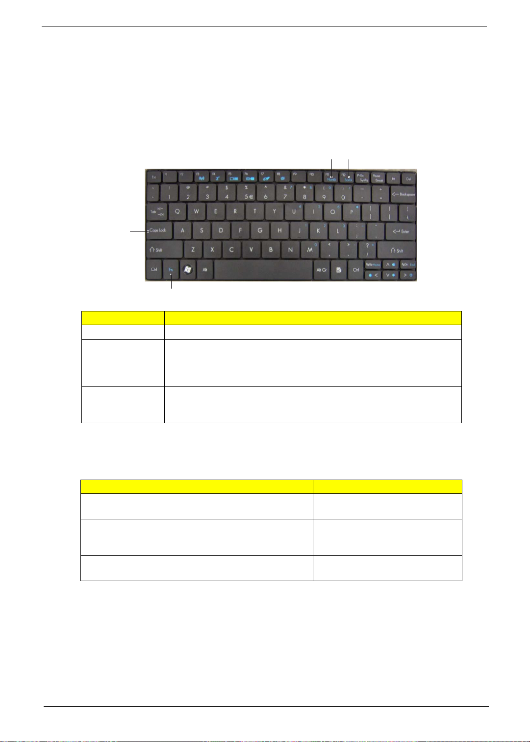
Lock Keys and embedded numeric keypad*
The keyboard has three lock keys which you can toggle on and off.
F11/
Num Lock
Caps Lock
Fn
Lock key Description
Caps Lock When Caps Lock is on, all alphabetic characters typed are in uppercase.
Num Lock
<Fn> + <F11>*
Scroll Lock
<Fn> + <F12>
When Num Lock is on, the embedded keypad is in numeric mode. The
keys function as a calculator (complete with the arithmetic operators +, -,
*, and /). Use this mode when you need to do a lot of numeric data entry. A
better solution would be to connect an external keypad.
When Scroll Lock is on, the screen moves one line up or down when you
press the up or down arrow keys respectively. Scroll Lock does not work
with some applications.
F12/
Scroll Lock
The embedded numeric keypad functions like a desktop numeric keypad. It is indicated by small characters
located on the upper right corner of the keycaps. To simplify the keyboard legend, cursor-control key symbols
are not printed on the keys.
Desired access Num Lock on Num Lock off
Number keys on
embedded keypad
Cursor-control
keys on embedded
keypad
Main keyboard
keys
* only for certain models
Chapter 1 15
Type numbers in a normal manner.
Hold <Shift> while using cursor-
control keys.
Hold <Fn> while typing letters on
embedded keypad.
Hold <Fn> while using cursorcontrol keys.
Type the letters in a normal manner.
Page 24
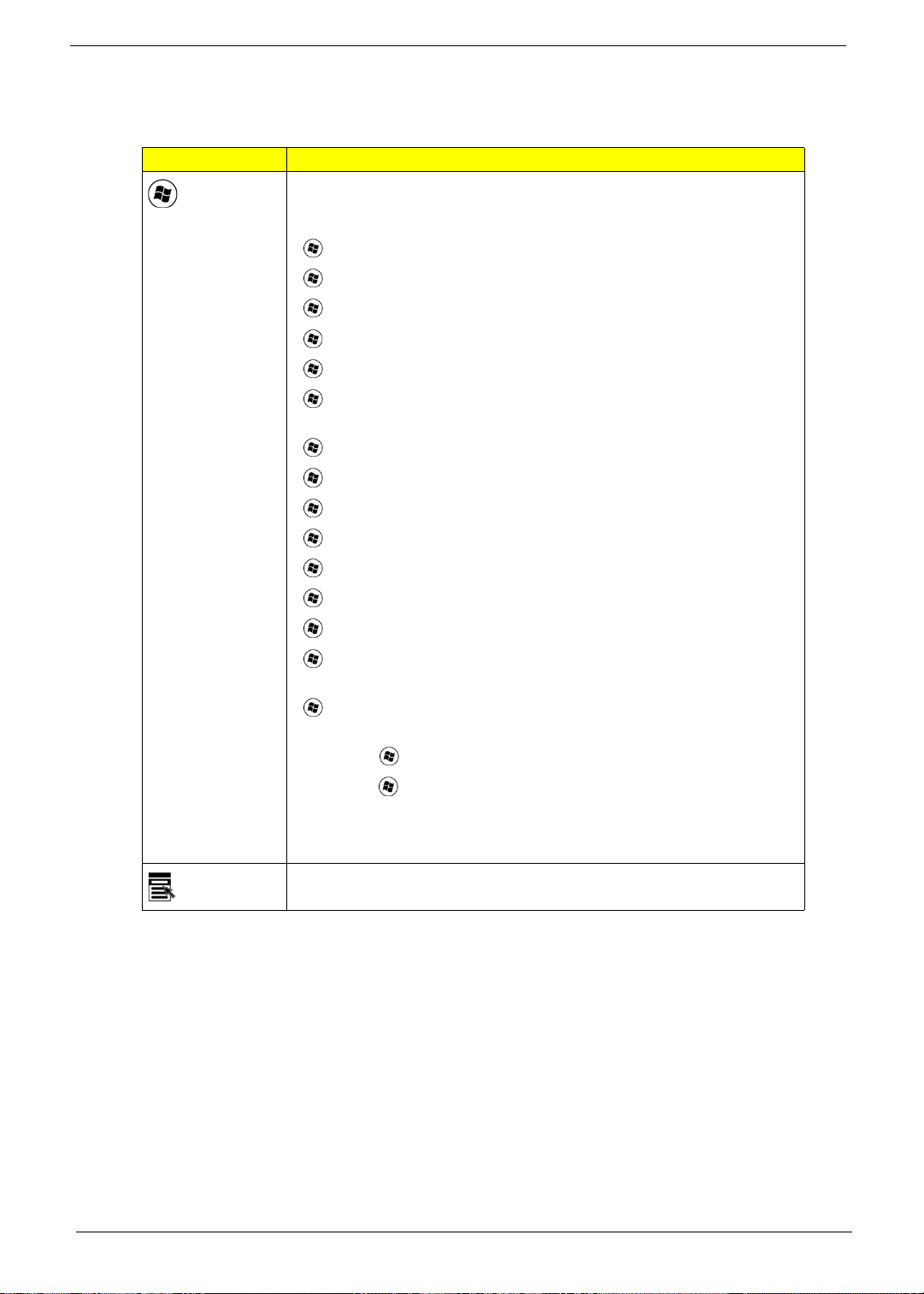
Windows Keys
The keyboard has two keys that perform Windows-specific functions.
Key Description
Windows
key
Pressed alone, this key has the same effect as clicking on the Windows
Start button; it launches the Start menu.
It can also be used with other keys to provide a variety of functions:
<> : Open or close the Start menu.
< > + <D>: Display the desktop.
< > + <E>: Open Windows Explore.
< > + <F>: Search for a file or folder.
< > + <G>: Cycle through Sidebar gadgets.
< > + <L>: Lock your computer (if you are connected to a network
domain), or switch users (if you're not connected to a network domain).
< > + <M>: Minimizes all windows.
< > + <R>: Open the Run dialog box.
< > + <T>: Cycle through programs on the taskbar.
< > + <U>: Open Ease of Access Center.
< > + <X>: Open Windows Mobility Center.
Application
key
< > + <BREAK>: Display the System Properties dialog box.
< > + <SHIFT+M>: Restore minimized windows to the desktop.
< > + <TAB>: Cycle through programs on the taskbar by using
Windows Flip 3-D.
< > + <SPACEBAR>: Bring all gadgets to the front and select Windows
Sidebar.
<CTRL> + < > + <F>: Search for computers (if you are on a network).
<CTRL> + < > + <TAB>: Use the arrow keys to cycle through programs
on the taskbar by using Windows Flip 3-D.
NOTE: Depending on your edition of Windows Vista, some shortcuts may
not function as described.
This key has the same effect as clicking the right mouse button; it opens
the application's context menu.
16 Chapter 1
Page 25
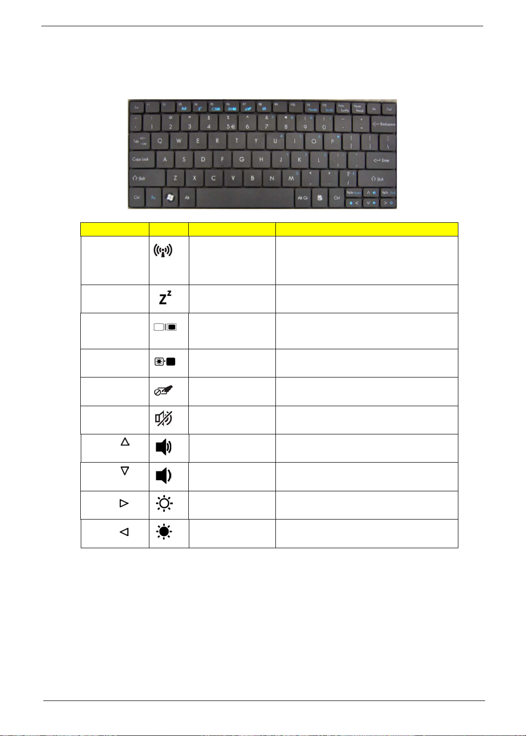
Hot Keys
The computer employs hotkeys or key combinations to access most of the computer's controls like screen
brightness and volume output.
To activate hot keys, press and hold the <Fn> key before pressing the other key in the hotkey combination.
Hotkey Icon Function Description
<Fn> + <F3> Communication Enables / disables the computer’s
communication devices.
(Communication devices may vary by
configuration.)
<Fn> + <F4> Sleep Puts the computer in Sleep mode.
<Fn> + <F5> Display toggle Switches display output between the display
screen, external monitor (if connected) and
both.
<Fn> + <F6> Display off Turns the display screen backlight off to save
power. Press any key to return.
<Fn> + <F7> Touchpad toggle Turns the touchpad on and off.
<Fn> + <F8> Speaker toggle Turns the speakers on and off.
<Fn> + < >
<Fn> + < >
<Fn> + < >
<Fn> + < >
Volume up Increases the sound volume.
Volume down Decreases the sound volume.
Brightness up Increases the screen brightness.
Brightness down Decreases the screen brightness.
Chapter 1 17
Page 26
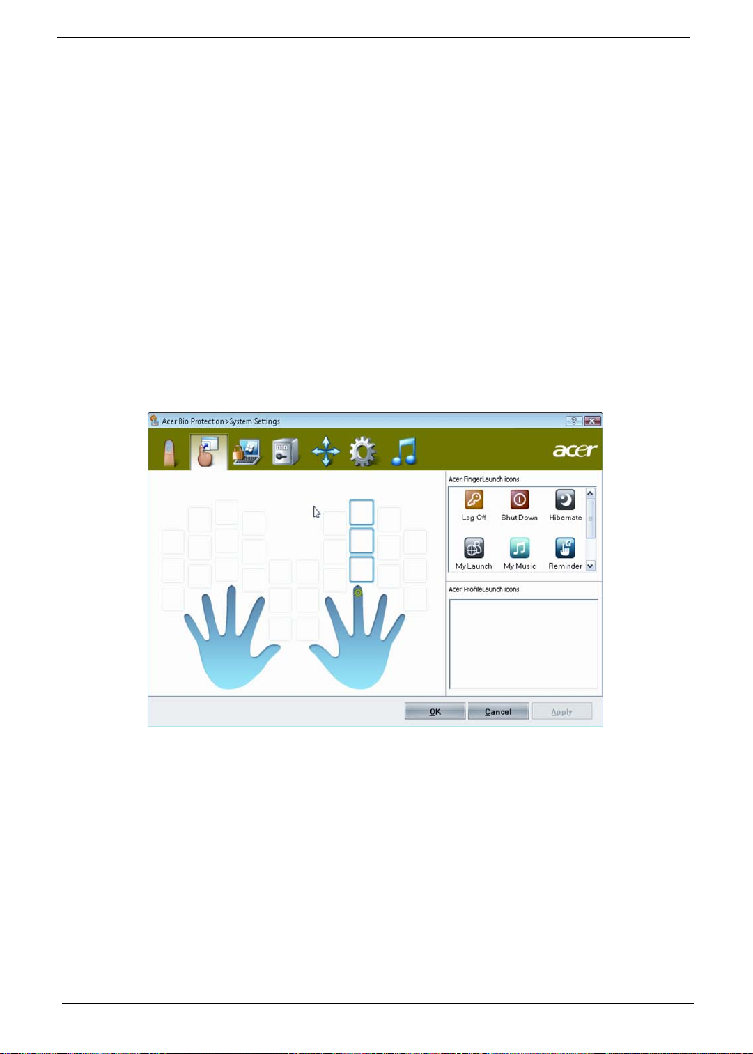
Using the system utilities
Acer Bio-Protection (only for certain models)
Acer Bio-Protection Fingerprint Solution is a multi-purpose fingerprint software package integrated with the
Microsoft Windows operating system. Utilizing the uniqueness of one's fingerprint, Acer Bio-Protection
Fingerprint Solution incorporates protection against unauthorized access to your computer with centralized
password management via Password Bank; easy music player launching with Acer MusicLaunch*; secure
Internet favorites via Acer MyLaunch*; and fast application/website launching and login with Acer
FingerLaunch. Acer ProfileLaunch** can launch up to three applications/ websites with a single finger swipe.
Acer Bio-Protection Fingerprint Solution also allows you to navigate through web browsers and documents
using Acer FingerNav*. With Acer Bio-Protection Fingerprint Solution, you can now enjoy an extra layer of
protection for your personal computer, as well as the convenience of accessing your daily tasks with a simple
swipe of your finger!
For more information, refer to the Acer Bio-Protection help files.
NOTE:
* Acer ProfileLaunch, MusicLaunch, MyLaunch and FingerNav are only available on select models.
** In models without Acer ProfileLaunch, Acer FingerLaunch can be used to open applications in the Acer
ProfileLaunch icons area; a single finger swipe will launch only one application at a time.
18 Chapter 1
Page 27
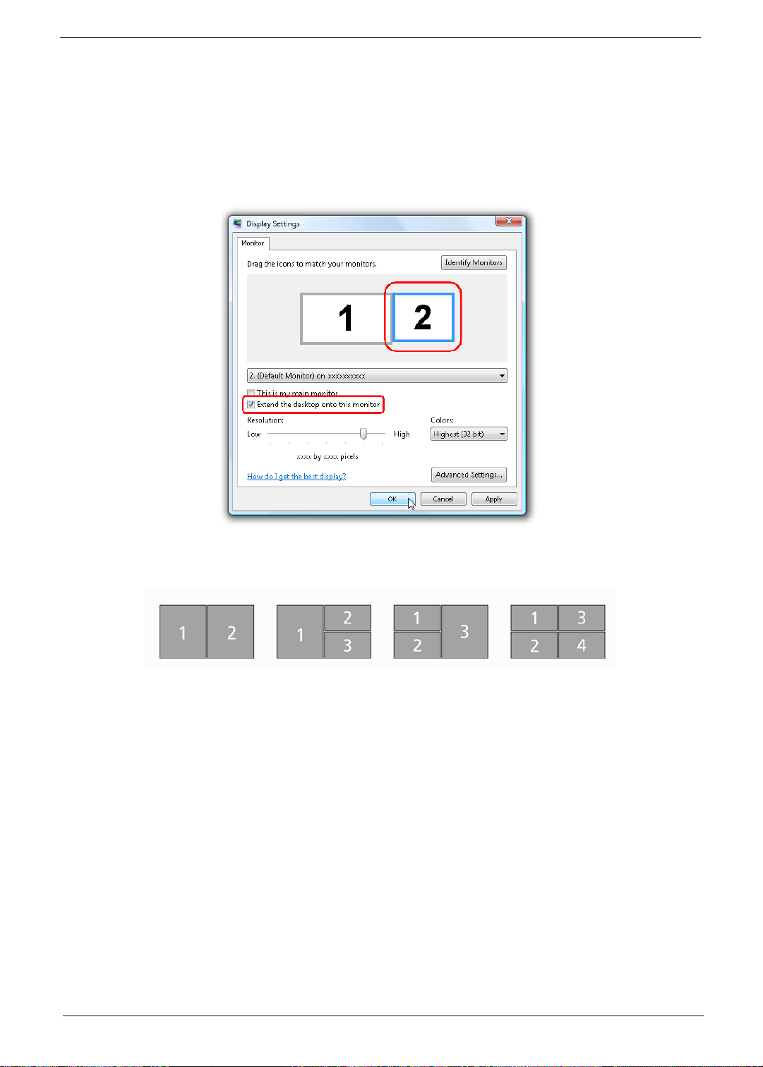
Acer GridVista (dual-display compatible)
NOTE: This feature is only available on certain models.
To enable the dual display feature of your notebook, first ensure that a second display is connected, then,
open the Display Settings properties box using the Control Panel or by right-clicking the Windows desktop and
selecting Personalize. Select the secondary monitor (2) icon in the display box and then click the check box
Extend the desktop onto this monitor. Finally, click Apply to confirm the new settings and click OK to
complete the process.
Acer GridVista is a handy utility that offers four pre-defined display settings so you can view multiple windows
on the same screen. To access this function, please go to Start, All Programs and click on Acer GridVista.
You may choose any one of the four display settings indicated below:
Double (vertical), Triple (primary at left), Triple (primary at right), or Quad.
Acer Gridvista is dual-display compatible, allowing two displays to be partitioned independently.
Acer GridVista is imple to set up:
1. Run Acer GridVista and select your preferred screen configuration for each display from the taskbar.
2. Drag and drop each window into the appropriate grid.
Chapter 1 19
Page 28
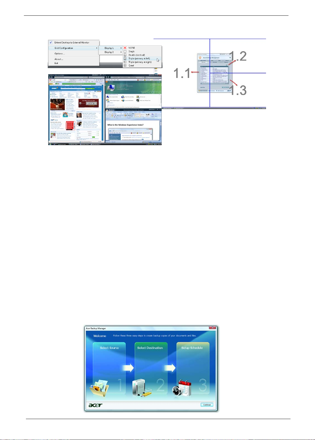
3. Enjoy the convenience of a well-organized desktop.
NOTE: Please ensure that the resolution setting of the second monitor is set to the manufacturer's
recommended value.
Acer Backup Manager
NOTE: This feature is only available on certain models.
Acer Backup Manager is a simple three-step process that allows you to create backup copies of your entire
system or selected files and folders according to a schedule or as you need to.
To start Acer Backup Manager, press the Acer Backup Manager key above the keyboard. Alternatively, you
can go to Start > All Programs > Acer Backup Manager > Acer Backup Manager. This will open the
Welcome screen; from this screen you will be taken through the three steps to setup scheduled back ups.
Click Continue to proceed to the following screen. Click the + button and follow the onscreen instructions:
1. Select the content you want to back up. The less content you select, the quicker the process will be, but it
will increase your risks of losing data.
2. Select where you want the backup copies to be stored. You will need to select an external drive or your D:
drive; Acer Backup Manager cannot store a backup on the source drive.
3. Select how often you want Acer Backup Manager to create back ups.
Once you have finished these three steps, backups will be created according to the schedule. You can also
create backups manually by pressing the Acer Backup Manager key.
If you wish to change your settings at any time, run Acer Backup Manager from the Start menu and go
through the steps outlined above.
20 Chapter 1
Page 29

Power management
This computer has a built-in power management unit that monitors system activity. System activity refers to
any activity involving one or more of the following devices: keyboard, mouse, hard disk, peripherals connected
to the computer, and video memory. If no activity is detected for a period of time (called an inactivity timeout),
the computer stops some or all of these devices in order to conserve energy.
This computer employs a power management scheme that supports the advanced configuration and power
interface (ACPI), which allows for maximum power conservation and maximum performance at the same
time. Windows handles all power-saving chores for your computer.
Acer PowerSmart key
The Acer PowerSmart key uses the power-saving features of your computer's graphics sub-system to reduce
overall power consumption. When you press the Acer PowerSmart key, the screen brightness is reduced and
the graphics chip switched to a lower speed; PCI and WLAN switch to power-saving modes. Press the Acer
PowerSmart key again to return to your previous settings.
NOTE: This feature is only available on certain models.
Acer eRecovery Management
Acer eRecovery Management is a tool to quickly restore the system. You can back up/restore the factory
default image, and reinstall applications and drivers.
NOTE: All of the following content is for general reference only. Actual product specifications may vary.
Acer eRecovery Management consists of the following functions:
1. Backup:
z Create Factory Default Disc
z Create Drivers and Applications Disc
2. Restore:
z Completely Restore System to Factory Defaults
z Restore Operating System and Retain User Data
z Reinstall Drivers or Applications
This chapter will guide you through each process.
NOTE: This feature is only available on certain models. For systems that do not have a built-in optical disc
burner, plug in an external optical disc burner before entering Acer eRecovery Management for
optical disc-related tasks.
To use the password protection feature of Acer eRecovery Management, you must first set the password. The
password is set by launching Acer eRecovery Management and clicking Settings.
Chapter 1 21
Page 30
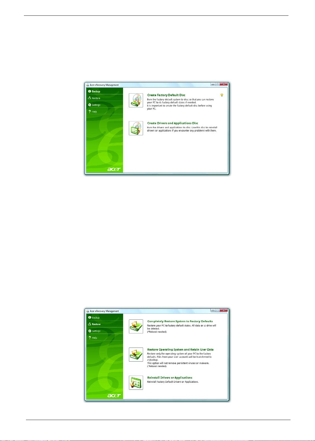
Burn backup discs
From the Backup page of Acer eRecovery Management, you can burn the factory default image or back up
drivers and applications.
1. Click on Start > All Programs > Acer > Acer eRecovery Management.
2. Acer eRecovery Management opens to the Backup page.
3. Select the type of backup (factory default or drivers and applications) you would like to burn to disc.
4. Follow the instructions on screen to complete the process.
NOTE: Create a factory default image when you want to burn a bootable disc that contains your computer's
entire operating system as it was delivered to you from the factory. If you wish to have a disc that will
allow you to browse the contents and install selected drivers and applications, create a drivers and
application backup instead — this disc will not be bootable.
Restore
The restore feature allows you to restore or recover the system from a factory default image or from previously
created CD and DVD backups. You can also reinstall applications and drivers for your Acer system.
1. Click on Start, All Programs, Acer, Acer eRecovery Management.
2. Switch to the Restore page by clicking Restore.
22 Chapter 1
Page 31

3. You can choose to restore the system from a factory default image or reinstall applications and drivers.
4. Follow the instructions on screen to complete the process.
Restore Windows Vista from backup discs
To restore Windows Vista from your previously burned backup discs, you will need to insert the first backup
disc and enable the F12 Boot Menu via the BIOS Setup Utility.
1. Turn on your computer and insert the first system recovery disc into the optical disc drive. Restart your
computer.
2. During startup when the Acer logo shows, press the F2 key to enter BIOS Setup, where you can set
system parameters.
3. Use the left and right arrow keys to select the Main submenu.
4. Use the up and down arrow keys to select F12 Boot Menu.
5. Use the F5 or F6 key to change F12 Boot Menu to Enabled.
6. Press the ESC key to enter the Exit submenu, press the ENTER key to Exit Saving Changes. Press the
ENTER key again to select Yes. The system will reboot.
7. After rebooting, when the Acer logo shows, press the F12 key to open the Boot Menu. Here you can
select which device to boot from.
8. Use the arrow keys to select the IDE CD, then press the ENTER key. Windows will be installed from the
recovery disc.
9. Insert the second recovery disc when prompted, then follow the onscreen prompts to complete the
restore.
10. Remove the recovery disc from the optical drive once the restore is complete. Do this before rebooting
your computer.
If you prefer to set the boot priority for long-term use, you should select the Boot submenu.
1. Turn on your computer and insert the first system recovery disc into the optical disc drive. Restart your
computer.
2. During startup when the Acer logo shows, press the
system parameters.
3. Use the left and right arrow keys to select the Boot subme
4. Use the up and down arrow keys to select the IDE CD device.
5. Use the F6 key to move the IDE CD device to the highest boot priority, or use the F5 key to move other
devices to a lower boot priority. Ensure that the IDE CD device is the highest priority.
6. Press the ESC key to enter the Exit submenu, press the ENTER key to Exit Saving Changes. Press the
ENTER key again to select Yes. The system will reboot.
7. When you reboot, Windows will be installed from the recovery disc.
8. Insert the second recovery disc when prompted, then follow the onscreen prompts to complete the
restore.
9. Remove the recovery disc from the optical drive once the restore is complete. Do this before rebooting
your computer.
F2 key to enter BIOS Setup, where you can set
Chapter 1 23
Page 32

Hardware Specifications and Configurations
Processor
Item Specification
Type Core i5-540UM
Description CPU intel Core i5 540UM 1.2G 18W
L3 Cache 8MB
FSB 1.20GHz
TDP (Thermal) 10W
Socket type BGA
Second Level Cache
Item Specification
North Bridge CPU + GMCH
South Bridge Ibexpeak-M HM55
System Memory
Item Specification
Technology DDR3 1066 / 1333MHz
Base memory
Expansion memory
Maximum memory size 8GB (Thermal evaluation bsed on 8GB)
DDR3 SO-DIMM x 1 slot (1024) / 2048 / 4096MB DDR3
SDRAM
DDR3 SO-DIMM x 1 slot (1024) / 2048 / 4096MB DDR3
SDRAM
Lan Interface
Item Specification
Controller (AVAP) Broadcom BCM57760
SPEED 10 / 100 / 1000Mb/s
Wireless LAN
Item Specification
Module Intel PP / CP 3rd WiFi 1x2 / 2x2 / BGN/N
Interface Mini Card
Antenna 2
Pointing Device
Item Specification
Glide Multi-touch touch PAD
24 Chapter 1
Page 33

Bluetooth Interface
Item Specification
Module FOX_BRM_2046 T60G928.11
Antenna on board
controller CSR
Bluetooth module Internal USB 2.0
Hard Disk Drive Interface
Item Specification
HDD form factor
9.5 mm high / 12.5 mm high / solid state disks
Media I/F SATA
IDE Controller SATA 150 MB/s
Audio Interface
Item Specification
Sound Codec (AVAP) Conexant CX20672-11Z
Internal Speakers 2 (1.5 Watt)
Internal Microphone Array MIC x 1
Sound Volume By Hot Key
LCD panel
Item Specification
Vendor and model name LED LCD AUO 11.6" WXGA B116XW02 V0 8ms 500:1
LED LCD LPL 11.6" WXGA LP116WH1-TLN1 LF 200nit
8ms 500:1
LED LCD CMO 11.6" WXGA N116B6-L02 C2 LF 200nit
10ms 500:1
LED LCD SAMSUNG 11.6" WXGA LTN116AT03 LF 200nit
16ms 500:1
Screen Diagonal [mm] 293.83
Active Area [mm] 256.125 X 144.0
Pixels H x V 1366x3(RGB) x 768
Pixel Pitch [mm] 0.1875 x 0.1875
Pixel Format R.G.B. Vertical Stripe
Display Mode Normally White
White Luminance (ILED=20mA)
2
]
[cd/m
(Note: ILED is LED current)
Luminance Uniformity 1.25 max. (5 points)
Contrast Ratio 500:1 typ
Response Time [ms] 8 typ / 16 Max
Nominal Input Voltage VDD [Volt] +3.3 typ.
Power Consumption [Watt] 4.0 max. (Include Logic and Blu power)
Weight[Grams] 255g max.
200 typ. (5 points average)
170 min. (5 points average)
Chapter 1 25
Page 34

Item Specification
Physical Size
Include bracket [mm]
Length 267.5 268.0 268.5
Min. Typ. Max
Width 161.0 161.5 162.0
Thickness - - 5.2
Electrical Interface 1 channel LVDS
Glass Thickness [mm] 0.5
Surface Treatment Glare, Hardness 3H,
Reflection <4%
Support Color 262K colors ( RGB 6-bit )
Temperature Range
o
Operating[
C]
Storage (Non-Operating)[
o
C]
0 to +50
-20 to +60
RoHS Compliance RoHS Compliance
Viewing Angle [degree] Min. Typ.
Horizontal(Right) 40 45
CR=10(Left) 40 45
Veritical(Upper) 10 15
CR=10(Lowe r) 30 3 0
Brightness Brightness controlled by Hot Keys
Card Slot
Item Specification
5 in 1 card reader (SD/MMC/MS/
MSPro/xD)
WebCAM
Item Specification
Module 1.3M
Interface USB
RTS5128, supported 8GB (test pass)
26 Chapter 1
Page 35

Keyboard
Item Specification
Controller Acer NT1T
I/O
Item Specification
Monitor(VGA) Yes
HDMI No
USB 3
Stereo Mic-in 1
SPDIF 1
RJ45 1
mini card socket(Full size) Full mini card (3G) x 1 & Half mini card (SP WLAN) x 1
Button
Item Specification
Power on/off (with Visiable LED) 1 (mechanical, Blue)
WLAN None
3G/BT None
Launch key module(Follow spec) None
Back up key None
Power consumption key None
Volume Control None
Software
Item Specification
Operation system Windows 7
BIOS Insyde H2O
Power Management
Item Specification
Controller ITE ITE8512F
Interface LPC
AC adapter (AVAP) 30W
1st Battery (AVAP) 3-cell 2.2Ah
6-cell 4.4Ah
6-cell 5.6Ah
Chapter 1 27
Page 36

LED Status Indicator
Item Specification
Power Status 1 (Blue / Orange)
1st Battery Status 1 (Blue / Orange)
HDD 1 (Blue)
Caps Lock 1 (Blue)
Num Lock 1 (Blue)
Wireless LAN 1 (Blue / Orange)
Bluetooth 1 (Blue)
Security Features
Item Specification
Kensington Lock Hole(7.5 mm
1
diameter)
Fingerprint Optional
TPM None
FAN
Item Specification
Not Noise as low as possible
Number 1
Physical Characteristics
Item Specification
Dimensions 285mm x 206.3mm
Thickness (maximum) 20.2 ~ 29.1mm
Weight (incl 1st Battery & super
multi ODD)
Ta rg e t < 1.35kg
28 Chapter 1
Page 37

Chapter 2
System Utilities
BIOS Setup Utility
The BIOS Setup Utility is a hardware configuration program built into your computer’s BIOS (Basic Input /
Output System).
Your computer is already properly configured and optimized, and you do not need to run this utility. However, if
you encounter configuration problems, you may need to run Setup.Please also refer to Chapter 4
Troubleshooting when problem arises.
To activate the BIOS Utility, press m during POST (when “Press <F2> to enter Setup” message is prompted on
the bottom of screen).
Press m to enter setup. The default parameter of F12 Boot Menu is set to “disabled”. If you want to change
boot device without entering BIOS Setup Utility, please set the parameter to “enabled”.
Press <F12> during POST to enter multi-boot menu. In this menu, user can change boot device without
entering BIOS SETUP Utility.
InsydeH2O Setup Utility Rev. 3.0
Information Main Advanced Security Boot Exit
CPU Type: Genuine Intel( R ) CPU
CPU Speed: T2300 @ 1.66GHz
IDE 0 Model Name:
IDE0 Serial Number:
ATAPI Model Name: MATSHITADVD
System BIOS Version: V1.00
VGA BIOS Version: ATI V008.050I.0-26.00
Serial Number: xxxxxxxxxxxxxxxxxxxx (Max: 22 Byte)
Asset Tag Number: xxxxxxxxxxxxxxxxxxxx (Max: 32 Byte)
Product Name: xxxxxxxxxxxxxxxxxxxx (Max: 16 Byte)
UUID: xxxxxxxxxxxxxxxxxxxx (Max: 16 Byte)
ST960821A-(PM)
3LF005DB
F1 Help ↑↓ Select Item F5/F6 Change Values F9 Setup defaults
Esc Exit ←→ Select Menu Enter Select4Sub-Menu F10 Save and Exit
Chapter 2 29
Page 38

Invoking BIOS Setup
The setup function can only be invoked by pressing F2 when Press <F2> to enter Setup message is prompted
on the bottom of screen during POST.
The setup uses a menu driven interface to allow the user to configure their system. The features are divided
into 5 parts as follows:
Information Display the system informations.
Main allows the user to specify standard IBM PC AT system parameters.
Security Provides security settings of the system.
Boot Allows the user to specify the boot options.
Exit Allows the user to save CMOS setting and exit Setup.
NOTE: You can change the value of a parameter if it is enclosed in square brackets. Navigation keys for a
particular menu are shown on the bottom of the screen. Help for parameters are found in the Item
Specific Help part of the screen. Read this carefully when making changes to parameter values.
Please note that system information is subject to different models.
Information
InsydeH2O Setup Utility Rev. 3.0
Information Main Advanced Security Boot Exit
CPU Type: Genuine Intel( R ) CPU
CPU Speed: T2300 @ 1.66GHz
IDE 0 Model Name:
IDE0 Serial Number:
ATAPI Model Name: MATSHITADVD
System BIOS Version: V1.00
VGA BIOS Version: ATI V008.050I.0-26.00
Serial Number: xxxxxxxxxxxxxxxxxxxx (Max: 22 Byte)
Asset Tag Number: xxxxxxxxxxxxxxxxxxxx (Max: 32 Byte)
Product Name: xxxxxxxxxxxxxxxxxxxx (Max: 16 Byte)
UUID: xxxxxxxxxxxxxxxxxxxx (Max: 16 Byte)
ST960821A-(PM)
3LF005DB
F1 Help ↑↓ Select Item F5/F6 Change Values F9 Setup defaults
Esc Exit ←→ Select Menu Enter Select4Sub-Menu F10 Save and Exit
NOTE: Other fields are informational items and are unit dependent.
Parameter Description
CPU Type This field shows the CPU type of the system.
CPU Speed This field shows the CPU speed of the system.
IDE0 Model Name The field shows the Model name of HDD installed on Primary
IDE master.
30 Chapter 2
Page 39

Parameter Description
IDE0 Serial Number The field shows the Serial number of HDD installed on Primary
IDE master.
ATAPI Model Name
The field shows the Model name of ATAPI.
System BIOS version Displays system BIOS version.
VGA BIOS Version This field displays the VGA firmware version of the system.
Serial Number This field displays the serial number of this unit.
Asset Tag Number This field displays the asset tag number of the system.
Product Name This field shows product name of the system.
UUID Number This will be visible only when an internal LAN device is
presenting.
UUID=32bytes
Main
The Main screen displays a summary of your computer hardware information, and also includes basic setup
parameters. It allows the user to specify standard IBM PC AT system parameters.
InsydeH2O Setup Utility Rev. 3.0
Information Main Advanced Security Boot Exit
Item specific Help
System Time: [09:00:00] <Tab>, <Shift-Tab>, or
System Date: [01/01/2003] <Enter> selects field
Total Memory [xxxxMB]
Video Memory: [XMB]
Graphic mode [Switchable]
Quiet Boot: [Enabled]
Network boot: [Enabled]
F12 Boot Menu: [Disabled]
D2D Recovery: [Enabled]
F1 Help ↑↓ Select Item F5/F6 Change Values F9 Setup defaults
Esc Exit ←→ Select Menu Enter Select4Sub-Menu F10 Save and Exit
NOTE: The screen above is for your reference only. Actual values may differ.
Chapter 2 31
Page 40

The table below describes the parameters in this screen. Settings in boldface are the default and suggested
parameter settings.
Parameter Description Format/Option
System Time Sets the system time. The hours are
displayed with 24-hour format.
Format: HH:MM:SS
(hour:minute:second)
System Time
System Date Sets the system date. Format: MM/DD/YYYY
(month/day/year)
System Date
Total Memory This field reports the memory size of total
memory in the system.
Video Memor Shows the Video memory size.
Graphic mode The following define the options of graphic
mode for different skus:
For Mux_less projects: Switchable/
Integrated
Others: Switchable/Discrete
Quiet Boot Determines if Customer Logo will be
displayed or not; shows Summary Screen
Option: Enabled or
Disabled
is disabled or enabled.
Enabled: Customer Logo is displayed, and
Summary Screen is disabled.
Disabled: Customer Logo is not displayed,
and Summary Screen is enabled.
Network Boot Enables, disables the system boot from
LAN (remote server).
F12 Boot Menu Enables, disables Boot Menu during
POST.
D2D Recovery Enables, disables D2D Recovery function.
The function allows the user to create a
Option: Enabled or
Disabled
Option: Disabled or
Enabled
Option: Enabled or
Disabled
hidden partition on hard disc drive to store
operation system and restore the system
to factory defaults.
NOTE: The sub-items under each device will not be shown if the device control is set to disable or auto. This is
because the user is not allowed to control the settings in these cases.
NOTE: Please refer to Acer’s VGA TAG table.For Intel switchable graphic platforms, Video memory refers to
the dedicated VRAM size of discrete graphics.
AMD or NV UMA:
System memory >=512M, VRAM set to 256M
System memory < 512M, VRAM set to 64M
Others: (please refer to Acer VGA tAG table)
32 Chapter 2
Page 41

Security
The Security screen contains parameters that help safeguard and protect your computer from unauthorized
use.
InsydeH2O Setup Utility Rev. 3.0
Information. Main Advanced Security Boot Exit
Item specific Help
Supervisor Password Is Clear
User Password Is Clear Supervisor Password controls
HDD Password Clear access to the whole setup
utility. It can be used to boot
Set Supervisor Password [Enter] up when Password on boot is
Set User Password [Enter] enabled.
Set HDD Password [Enter]
Password on Boot: [Disabled]
F1 Help ↑↓ Select Item F5/F6 Change Values F9 Setup defaults
Esc Exit ←→ Select Menu Enter Select4Sub-Menu F10 Save and Exit
Chapter 2 33
Page 42

The table below describes the parameters in this screen. Settings in boldface are the default and suggested
parameter settings.
Parameter Description Option
Supervisor Password isShows the setting of the Supervisor
password.
User Password is Shows the setting of the user password. Clear or Set
HDD Password is Shows the setting of HDD password. Clear or Set
Set Supervisor Password
Set User Password Press Enter to set the user password.
Set Hdd Passwor Press Enter to set the Hdd password.
Password on Boot Defines whether a password is required or
Press Enter to set the supervisor password.
When set, this password protects the BIOS
Setup Utility from unauthorized access. The
user can not enter the Setup menu and
change he value of parameters.
When user password is set, this password
protects the BIOS Setup Utility from
unauthorized access.
The user can enter Setup menu only and
does not have right to change the value of
parameters.
When Hdd password is set, this
password protects the Hdd . Other
user can’t steal information.
not while the events defined in this group
happened. The following sub-options are all
requires the Supervisor password for
changes and should be grayed out if the
user password was used to enter setup.
Clear or Set
Disabled or Enabled
NOTE: When you are prompted to enter a password, you have three tries before the system halts. Don’t forget
your password. If you forget your password, you may have to return your notebook computer to your
dealer to reset it.
Set Supervisor Password
While these fields are highlighted and press ”Enter” , a window similar to the following is shown:
Set Supervisor Password
Enter New Password [ ]
Confirm New Password [ ]
If there is an old password then setup will prompt with the following window instead and a current password
will be required to be entered at first:
Set Supervisor Password
Enter current password [ ]
Enter New Password [ ]
Confirm New Password [ ]
34 Chapter 2
Page 43

User can now type password in field “ Enter New Password“, and
re-enter password in field “Confirm New Password“ for verification.
Set Supervisor Password
Enter current password [ ]
Enter New Password [ ]
Confirm New Password [ ]
If the verification is OK:
Setup Notice
Changes have been saved.
[ continue]
The password setting is complete after user presses enter.
Setup Warning
Invalid password
Re-enter Password
[ continue]
If the new password and confirm new password strings do not match:
Setup Warning
Password do not match
Re-enter Password
The format of the password is as follows:
Password Max Length : 8 characters.
Characters List Table:
A-Z Alphabets A through Z (Not Case Sensitive)
0-9 Numerical Characters.
-Dash
= Equal Sign
[ Left Bracket
] Right Bracket
.Period
, Comma
; Semi-colon
/Slash
\ Back-slash
Chapter 2 35
Page 44

Boot
This menu allows the user to decide the order of boot devices to load the operating system. Bootable devices
includes the distette drive in module bay, the onboard hard disk drive and the CD-ROM in module bay.
InsydeH2O Setup Utility Rev. 3.0
Information Main Advanced Security Boot Exit
Item specific Help
Boot priority order:
1. IDE 0: ST960821A
2: IDE 1: MATSHITADVD
3: USB FDD:
4. Network Boot: Realtek Boot Agent
5. USB HDD:
6. USB CDROM:
F1 Help ↑↓ Select Item F5/F6 Change Values F9 Setup defaults
Esc Exit ←→ Select Menu Enter Select4Sub-Menu F10 Save and Exit
Use <↑> or <↓> to select a
device, then press <F6> to move
it up the List, or <F5> to move it
down the list. Press <Esc> to
escape the menu
Exit
The Exit screen contains parameters that help safeguard and protect your computer from unauthorized use.
InsydeH2O Setup Utility Rev. 3.0
Information Main Advanced Security Boot Exit
Item specific Help
Exit Saving Changes Exit System Setup and save your
Exit Discarding Changes Changes
Load Setup Defaults Exit utility without saving Setup
Discard changes Data
Save changes Load default values for all SETUP
item.
F1 Help ↑↓ Select Item F5/F6 Change Values F9 Setup defaults
Esc Exit ←→ Select Menu Enter Select4Sub-Menu F10 Save and Exit
36 Chapter 2
Page 45

The table below describes the parameters in this screen.
Parameter Description
Exit Saving Changes Exit System Setup and save your changes to CMOS.
Exit Discarding Changes
Load Setup Default Load default values for all SETUP item.
Discard Changes Load previous values from CMOS for all SETUP items.
Save Changes Save Setup Data to CMOS.
Exit utility without saving setup data to CMOS.
Exit Saving Changes
Allows the user to save changes and reboot the system.
The following message is shown when user presses
Setup Confirmation
Save configuration changes and exit now
[ Yes] [No]
System will reboot if Yes is selected and will stay in Setup if No is selected..
“Enter” on the item
Exit Discarding Changes
Allows the user to not save changes before exiting Setup.
The following message is shown when user presses
Exit discarding changes?
[Yes] [No]
System will reboot after either selection.
“Enter” on this item.
Load Setup Default
Allows the user to load default values in Setup. The following message is shown when user presses “Enter”
on this item:.
Setup Confirmation
Load default configuration now?
[ Yes] [No]
It still stay in Setup after either selection.
Chapter 2 37
Page 46

Discard Changes
Allows the user to discard previous changes in Setup.
The following message is shown when user presses “Enter” on this item:
Setup Confirmation
Load previous configuration now?
[ Yes] [No]
Save Changes
Allows the user to save current changes in Setup.
The following message is shown when user presses
Setup Confirmation
Save configuration changes now?
[ Yes] [No]
“Enter” on this item:
38 Chapter 2
Page 47

BIOS Flash Utility
The BIOS flash memory update is required for the following conditions:
New versions of system programs
New features or options
Restore a BIOS when it becomes corrupted.
Use the Phlash utility to update the system BIOS flash ROM.
NOTE: If you do not have a crisis recovery diskette at hand, then you should create a Crisis Recovery
Diskette before you use the Phlash utility.
NOTE: Do not install memory-related drivers (XMS, EMS, DPMI) when you use the Phlash.
NOTE: Please use the AC adaptor power supply when you run the Phlash utility. If the battery pack does not
contain enough power to finish BIOS flash, you may not boot the system because the BIOS is not
completely loaded.
Fellow the steps below to run the Phlash.
1. Prepare a bootable diskette.
2. Copy the flash utilities to the bootable diskette.
3. Then boot the system from the bootable diskette. The flash utility has auto-execution function.
Chapter 2 39
Page 48

DOS flash BIOS SOP
1. Please prepare a bootable flash disk.
2. Unzip the “BIOS” and leave the DOS file in the bootable flash disk.
40 Chapter 2
Page 49

3. Insert the flash disk with the unzip file.
4. Connect the adapter.
Chapter 2 41
Page 50

5. Log in the DOS by bootable flash disk and type the name of “exe file”and press Enter. The system will
flash BIOS automatically.
NOTE: The version of BIOS must be newer than original version.
NOTE: Adapter have to be connected.
42 Chapter 2
Page 51

Clean BIOS Password SOP
1. Please prepare a bootable flash disk.
2. Unzip the “CleanBIOSPassword” and leave it in the bootable flash disk.
Chapter 2 43
Page 52

3. Insert the flash disk with the unzip file.
4. Connect the adapter.
44 Chapter 2
Page 53

5. Set the supervisor BIOS and enable Power on Password.
6. Please insert bootable USB device, and press “alt gr+backspace+Esc” and press power button.
Chapter 2 45
Page 54

7. The system will automatically ignore the power on password and log in the bootable flash disk.
8. Insert “clearbpw” .
46 Chapter 2
Page 55

9. When the screen show “Clear the SU PWs completely” means the BIOS password removed
completely.
Chapter 2 47
Page 56

Clean HDD Password SOP
1. Please prepare a bootable flash disk.
2. Unzip the “CleanHDDPassword” and leave it in the bootable flash disk.
48 Chapter 2
Page 57

3. Insert the flash disk with the unzip file.
4. Connect the adapter.
Chapter 2 49
Page 58

5. After inserting the wrong HDD password three times. The system will show select item screen.
6. Memorize the error code behind the “Enter Unlock Password” .
NOTE: the number will be created by system in disorder.
50 Chapter 2
Page 59

7. Remove the disk and insert it in other system.
8. Log in DOS mode in other system. Execute the “Unlockhd” in the bootable flash disk by insert the
keyword: “unlockhd+ space + error code” .
Chapter 2 51
Page 60

9. The program will create a password. Please memorize it.
10. Remove the bootable flash disk and re-install in the original system.
52 Chapter 2
Page 61

11. Enter the password and the HDD lock will be released.
Chapter 2 53
Page 62

Crisis Disk SOP
1. Please prepare a bootable flash disk.
2. Unzip the “Crisis disk” and leave it in the bootable flash disk.
54 Chapter 2
Page 63

3. Insert the flash disk with the unzip file.
4. Connect the adapter.
Chapter 2 55
Page 64

5. Press “Fn+ESC+Power” to power on the system.
6. The system will automatically power on after several minutes.
7. Please use normal BIOS flash procedure to flash BIOS again when the machine be rescued.
56 Chapter 2
Page 65

DMI Utility SOP
1. Please prepare a bootable flash disk.
2. Unzip the “dmi174” and leave it in the bootable flash disk.
Chapter 2 57
Page 66

3. Insert the flash disk with the unzip file.
4. Connect the adapter.
58 Chapter 2
Page 67

5. Log in dos mode and type “dmi174r” to execute the program.
6. Activate the program.
Chapter 2 59
Page 68

7. Type “DMI174 /?” can check all of the function of DMI.
60 Chapter 2
Page 69

LAN EEPROM Utility SOP
1. Please prepare a bootable flash disk.
2. Unzip the MAC.zip and leave it in the bootable flash disk.
Chapter 2 61
Page 70

3. Insert the flash disk with the unzip file.
4. Connect the adapter.
62 Chapter 2
Page 71

5. Power on the system and press F2 to log in the BIOS. Select the USB HDD to the first priority.
6. Save the BIOS setting, the system will reboot automatically and log in DOS.
Chapter 2 63
Page 72

7. Go in to the file of MAC. Insert the “ßmacin.bat” .
8. Input the MAC address.
64 Chapter 2
Page 73

Winflash SOP
1. Please prepare a bootable flash disk.
2. Unzip the file and leave it in the flash disk.
Chapter 2 65
Page 74

3. Insert the flash disk with the unzip file.
4. Connect the adapter.
66 Chapter 2
Page 75

5. Double click the Winflash tool and begin to flash BIOS.
NOTE: The version of BIOS must be newer than original version.
NOTE: Adapter have to be connected.
Chapter 2 67
Page 76

68 Chapter 2
Page 77

Machine Disassembly and Replacement
Disassembly Requirements
To disassemble the computer, you need the following tools:
Wrist grounding strap and conductive mat for preventing electrostatic discharge
Flat screwdriver
Philips screwdriver
Plastic flat screwdriver
Plastic tweezers
NOTE: The screws for the different components vary in size. During the disassembly process, group the
screws with the corresponding components to avoid mismatch when putting back the components
Related Information
The product previews seen in the disassembly procedures may not represent the final product color or
configuration.
IMPORTANT: Cable paths and positioning may not represent the actual model. During the removal and
replacement of components, ensure all available cable channels and clips are used and that the
cables are replaced in the same postion.
Chapter 3
Replacement Requirements
NOTE: Cabling and components require adhesive to be applied during the replacement and reassembly
process.
NOTE: During manufacture a cyanoacrylate glue is used provided by Holdtite Adhesives LTD. This is not a
specified requirement. The reassembler is free to select an alternative appropriate adhesive.
Chapter 3 69
Page 78

Pre-disassembly Instructions
Before proceeding with the disassembly procedure, make sure that you do the following:
1. Turn off the power to the system and all peripherals.
2. Unplug the AC adapter and all power and signal cables from the system.
3. Place the system on a flat, stable surface.
70 Chapter 3
Page 79

Disassemble Process
The disassembly process is divided into the following sections:
External components disassembly
Main unit disassembly
LCD module disassembly
The flowcharts provided in the succeeding disassembly sections illustrate the entire disassembly sequence.
Observe the order of the sequence to avoid damage to any of the hardware components. For example, if you
want to remove the Mainboard, you must first remove the Keyboard, and LCD Module then disassemble the
inside assembly frame in that order.
Main Screw List
Screw Quantity Acer part no
M2.5*4L 12
M2*6L 11
M2*3 7
M2*2.5 4
External Module Disassembly Process
NOTE: The product previews seen in the disassembly procedures may not represent the final product color or
configuration.
Screw List
Wireless Module Disassembly M2.5*4L 2
Step Screw Quantity part no
Chapter 3 71
Page 80

Removing the Battery Pack
1. Turn the computer over.
2. Slide the battery lock/unlock latch to the unlock position.
72 Chapter 3
Page 81

3. Slide and hold the battery to the release position (1) and remove the battery from the main unit (2).
Chapter 3 73
Page 82

Removing the HDD
1. Remove two (2) screws on the HDD cover.
74 Chapter 3
Page 83

2. Remove the HDD cover.
3. Grasp the pull tab on the top of HDD.
Chapter 3 75
Page 84

4. Lift the HDD out of lower case.
5. Remove the HDD connector.
76 Chapter 3
Page 85

6. Remove the HDD bracket.
7. Remove the HDD pocket.
Chapter 3 77
Page 86

Removing the DIMM module
1. Remove two screws on the RAM cover.
78 Chapter 3
Page 87

2. Remove the RAM cover.Remove the RAM cover.
3. Remove the first RAM from RAM slot.
Chapter 3 79
Page 88

4. Remove the second RAM from RAM slot.
80 Chapter 3
Page 89

Remove the Wireless module
1. Notice the antenna color on the wireless card.
2. Release the cable of the wireless module.
Chapter 3 81
Page 90

3. Release two screws on the wireless module.
Typ e Numb er
M2.5*4 2
4. Remove wireless module.
82 Chapter 3
Page 91

LCD Module Disassembly Process
IMPORTANT: Cable paths and positioning may not represent the actual model. During the removal and
replacement of components, ensure all available cable channels and clips are used and that the
cables are replaced in the same position.
NOTE: The product previews seen in the disassembly procedures may not represent the final product color or
configuration.
Main Unit Disassembly Flowchar.
1.
Screw List
Step Screw Quantity part no
Upper Cover Disassembly M2.5*6L 2
Lower Cover Disassembly M2*6L 9
LCD Module Disassembly M2.5*4L 2
Power bracket Disassembly M2*3L 1
Mainboard Disassembly M2*3L 4
Mainboard Disassembly M2.5*4L 4
Chapter 3 83
Page 92

Removing the keyboard
1. Use tool to disconnect four latches which hold the keyboard.
2. Gently pry up the keyboard.
84 Chapter 3
Page 93

3. Carefully flip the keyboard over.
4. Unlock the keyboard FFC.
Chapter 3 85
Page 94

5. Disconnect the keyboard FFC.
86 Chapter 3
Page 95

Removing the Upper Case
1. Unlock the touch pad FFC.
2. Disconnect the Touch Pad FFC.
Chapter 3 87
Page 96

3. Unlock the power board FFC.
4. Disconnect the power board FFC.
88 Chapter 3
Page 97

5. Remove two screws on the topper case.
M2*6 2
Typ e Numb er
Chapter 3 89
Page 98

6. Remove all of the screws on the back of the notebook.
Typ e Numb er
M2*6
9
7. Remove the upper case.
90 Chapter 3
Page 99

Removing the LCD Module
1. Use the pull tab and Grab the LVDS cable.
2. Disconnect the LVDS cable.
Chapter 3 91
Page 100

3. Grab the tape on the WLAN cable.
4. Remove the tape on the WLAN cable.
92 Chapter 3
 Loading...