

Page 1

Acer M3 581T/581TG
SERVICEGUIDE
Page 2

Revision History
WARNING:
!
CAUTION:
!
IMPORTANT:
+
Refer to the table below for the updates made to this M3 581T/581TG service guide.
Date Chapter Updates
2012/2/29 Chapter 3 Update "Removing the
LCD Bezel"
Service guide files and updates are available on the ACER/CSD Website. For more
information, go to http://csd.acer.com.tw
.
Disclaimer
The information in this guide is subject to change without notice.
There are no representations or warranties, either expressed or implied, with respect to the
contents hereof and specifically disclaims any warranties of merchantability or fitness for any
particular purpose. The software described in this manual is sold or licensed "as is". Should
the programs prove defective following their purchase, the buyer (not the manufacturer,
distributor, or its dealer) assumes the entire cost of all necessary servicing, repair, and any
incidental or consequential damages resulting from any defect in the software.
Copyright
© 2012 by Acer Incorporated. All rights reserved. No part of this publication may be
reproduced, transmitted, transcribed, stored in a retrieval system, or translated into any
language or computer language, in any form or by any means, electronic, mechanical,
magnetic, optical, chemical, manual or otherwise, without the prior written permission of Acer
Incorporated.
Conventions
The following conventions are used in this manual:
Indicates a potential for personal injury.
Indicates a potential loss of data or damage to equipment.
Indicates information that is important to know for the proper completion of a
procedure, choice of an option, or completing a task.
The following typographical conventions are used in this document:
Book titles, directory names, file names, path names, and program/process names are shown in
italics.
ii
Example:
the DRS5 User's Guide
Page 3

/usr/local/bin/fd
the /TPH15spool_M program
Computer output (text that represents information displayed on a computer screen, such as
menus, prompts, responses to input, and error messages) are shown in constant width.
Example:
[01] The server has been stopped
User input (text that represents information entered by a computer user, such as command
names, option letters, and words) are shown in constant width bold.
Variables contained within user input are shown in angle brackets (< >).
Example:
At the prompt, type run <file name> -m
Keyboard keys are shown in bold italics.
Example:
After entering the data, press Enter.
General information 0
Before using this information and the product it supports, read the following general
information.
This service guide provides you with all technical information relating to the basic configuration
for Acer’s global product offering. To better fit local market requirements and enhance product
competitiveness, your regional office may have decided to extend the functionality of a
machine (such as add-on cards, modems, or extra memory capabilities). These localized
features are not covered in this generic service guide. In such cases, contact your regional
offices or the responsible personnel/channel to provide you with further technical details.
When ordering FRU parts: Check the most up-to-date information available on your regional
Web or channel. If, for whatever reason, a part number change is made, it may not be noted
in this printed service guide.
Acer-authorized Service Providers: Your Acer office may have a different part number code
than those given in the FRU list in this service guide. You must use the list provided by your
regional Acer office to order FRU parts for repair and service of customer machines.
iii
Page 4

iv
Page 5

CHAPTER 1
Hardware Specifications
Features . . . . . . . . . . . . . . . . . . . . . . . . . . . . . . . . . . . . . . . . . . . . 1-5
Operating System. . . . . . . . . . . . . . . . . . . . . . . . . . . . . . . . . . 1-5
Platform . . . . . . . . . . . . . . . . . . . . . . . . . . . . . . . . . . . . . . . . . 1-5
System Memory . . . . . . . . . . . . . . . . . . . . . . . . . . . . . . . . . . . 1-5
Display. . . . . . . . . . . . . . . . . . . . . . . . . . . . . . . . . . . . . . . . . . . 1-5
Graphics . . . . . . . . . . . . . . . . . . . . . . . . . . . . . . . . . . . . . . . . . 1-5
Storage Subsystem . . . . . . . . . . . . . . . . . . . . . . . . . . . . . . . . . 1-6
Audio Subsystem . . . . . . . . . . . . . . . . . . . . . . . . . . . . . . . . . . 1-6
Optical Media Drive . . . . . . . . . . . . . . . . . . . . . . . . . . . . . . . . 1-6
Communication . . . . . . . . . . . . . . . . . . . . . . . . . . . . . . . . . . . 1-6
Privacy Control . . . . . . . . . . . . . . . . . . . . . . . . . . . . . . . . . . . . 1-7
Dimensions and Weight. . . . . . . . . . . . . . . . . . . . . . . . . . . . . 1-7
Power Adapter and Battery. . . . . . . . . . . . . . . . . . . . . . . . . . 1-7
Special Keys and Controls . . . . . . . . . . . . . . . . . . . . . . . . . . . 1-8
I/O Ports. . . . . . . . . . . . . . . . . . . . . . . . . . . . . . . . . . . . . . . . . . 1-8
Software . . . . . . . . . . . . . . . . . . . . . . . . . . . . . . . . . . . . . . . . . 1-8
Environment . . . . . . . . . . . . . . . . . . . . . . . . . . . . . . . . . . . . . . 1-9
Notebook Tour. . . . . . . . . . . . . . . . . . . . . . . . . . . . . . . . . . . . . . . 1-11
Open Top View. . . . . . . . . . . . . . . . . . . . . . . . . . . . . . . . . . . . 1-11
Closed Front View . . . . . . . . . . . . . . . . . . . . . . . . . . . . . . . . . 1-12
Closed Rear View . . . . . . . . . . . . . . . . . . . . . . . . . . . . . . . . . . 1-12
Left View. . . . . . . . . . . . . . . . . . . . . . . . . . . . . . . . . . . . . . . . . 1-13
Right View . . . . . . . . . . . . . . . . . . . . . . . . . . . . . . . . . . . . . . . 1-14
Base View . . . . . . . . . . . . . . . . . . . . . . . . . . . . . . . . . . . . . . . . 1-15
Indicators . . . . . . . . . . . . . . . . . . . . . . . . . . . . . . . . . . . . . . . . 1-16
Touchpad Basics . . . . . . . . . . . . . . . . . . . . . . . . . . . . . . . . . . . 1-16
Using the Keyboard . . . . . . . . . . . . . . . . . . . . . . . . . . . . . . . . 1-17
Lock Keys. . . . . . . . . . . . . . . . . . . . . . . . . . . . . . . . . . . . . . . . . 1-18
Windows Keys. . . . . . . . . . . . . . . . . . . . . . . . . . . . . . . . . . . . . 1-19
Hotkeys . . . . . . . . . . . . . . . . . . . . . . . . . . . . . . . . . . . . . . . . . . 1-20
Specification Tables . . . . . . . . . . . . . . . . . . . . . . . . . . . . . . . . . . . 1-23
CHAPTER 2
System Utilities
BIOS Setup Utility. . . . . . . . . . . . . . . . . . . . . . . . . . . . . . . . . . . . . 2-3
Navigating the BIOS Utility . . . . . . . . . . . . . . . . . . . . . . . . . . 2-3
BIOS . . . . . . . . . . . . . . . . . . . . . . . . . . . . . . . . . . . . . . . . . . . . . . . 2-4
Information. . . . . . . . . . . . . . . . . . . . . . . . . . . . . . . . . . . . . . . 2-4
Main . . . . . . . . . . . . . . . . . . . . . . . . . . . . . . . . . . . . . . . . . . . . 2-6
i
Page 6

Security . . . . . . . . . . . . . . . . . . . . . . . . . . . . . . . . . . . . . . . . . . 2-8
Boot. . . . . . . . . . . . . . . . . . . . . . . . . . . . . . . . . . . . . . . . . . . . . 2-12
Exit. . . . . . . . . . . . . . . . . . . . . . . . . . . . . . . . . . . . . . . . . . . . . . 2-13
BIOS Flash Utilities . . . . . . . . . . . . . . . . . . . . . . . . . . . . . . . . . . . . 2-14
DOS Flash Utility. . . . . . . . . . . . . . . . . . . . . . . . . . . . . . . . . . . 2-15
WinFlash Utility . . . . . . . . . . . . . . . . . . . . . . . . . . . . . . . . . . . 2-17
Remove HDD/BIOS Password Utilities. . . . . . . . . . . . . . . . . . . . . 2-18
Remove HDD Password Utilities . . . . . . . . . . . . . . . . . . . . . . 2-18
Removing BIOS Passwords . . . . . . . . . . . . . . . . . . . . . . . . . . . 2-20
Cleaning BIOS Passwords . . . . . . . . . . . . . . . . . . . . . . . . . . . . 2-21
Using DMI Tools. . . . . . . . . . . . . . . . . . . . . . . . . . . . . . . . . . . . . . 2-22
LAN MAC EEPROM Utility . . . . . . . . . . . . . . . . . . . . . . . . . . . 2-29
CHAPTER 3
Machine Maintenance
Machine Disassembly and Replacement. . . . . . . . . . . . . . . . . . . 3-5
Recommended Equipment . . . . . . . . . . . . . . . . . . . . . . . . . . 3-5
Replacement Requirements. . . . . . . . . . . . . . . . . . . . . . . . . . 3-5
Pre-disassembly Instructions . . . . . . . . . . . . . . . . . . . . . . . . . 3-6
Disassembly Process . . . . . . . . . . . . . . . . . . . . . . . . . . . . . . . . 3-7
External Module Disassembly Process. . . . . . . . . . . . . . . . . . 3-8
External Modules Disassembly Flowchart. . . . . . . . . . . . . . . 3-8
Removing the Dummy Card. . . . . . . . . . . . . . . . . . . . . . . . . . 3-9
Removing the HDD Door . . . . . . . . . . . . . . . . . . . . . . . . . . . . 3-10
Removing the HDD Module. . . . . . . . . . . . . . . . . . . . . . . . . . 3-11
Removing the DIMM Module . . . . . . . . . . . . . . . . . . . . . . . . 3-12
Removing the SSD Module . . . . . . . . . . . . . . . . . . . . . . . . . . 3-13
Removing the WLAN Module . . . . . . . . . . . . . . . . . . . . . . . . 3-14
Removing the ODD Module . . . . . . . . . . . . . . . . . . . . . . . . . 3-16
Main Unit Disassembly Process . . . . . . . . . . . . . . . . . . . . . . . . . .3-19
Main Unit Disassembly Flowchart . . . . . . . . . . . . . . . . . . . . . 3-19
Removing the Top Case . . . . . . . . . . . . . . . . . . . . . . . . . . . . . 3-20
Removing battery. . . . . . . . . . . . . . . . . . . . . . . . . . . . . . . . . . 3-26
Removing the Power switch board . . . . . . . . . . . . . . . . . . . . 3-29
Remove the card reader. . . . . . . . . . . . . . . . . . . . . . . . . . . . . 3-30
Remove the cables from the Mainboard . . . . . . . . . . . . . . . 3-31
Removing the Mainboard . . . . . . . . . . . . . . . . . . . . . . . . . . . 3-34
Removing the Thermal module. . . . . . . . . . . . . . . . . . . . . . . 3-36
Removing the Bluetooth Board. . . . . . . . . . . . . . . . . . . . . . . 3-38
ii
Page 7

Removing the Speakers . . . . . . . . . . . . . . . . . . . . . . . . . . . . . 3-39
LCD Module Disassembly Process . . . . . . . . . . . . . . . . . . . . . . . . 3-41
LCD Module Disassembly Flowchart . . . . . . . . . . . . . . . . . . . 3-41
Removing the LCD Bezel . . . . . . . . . . . . . . . . . . . . . . . . . . . . 3-42
Removing the LCD Panel . . . . . . . . . . . . . . . . . . . . . . . . . . . . 3-46
Removing the Camera Board. . . . . . . . . . . . . . . . . . . . . . . . . 3-48
LCD Reassembly Procedure . . . . . . . . . . . . . . . . . . . . . . . . . . . . . 3-49
Replacing the Camera . . . . . . . . . . . . . . . . . . . . . . . . . . . . . . 3-49
Replacing the LCD Panel . . . . . . . . . . . . . . . . . . . . . . . . . . . . 3-50
Replacing the LCD Bezel . . . . . . . . . . . . . . . . . . . . . . . . . . . . 3-52
Replacing the Bluetooth . . . . . . . . . . . . . . . . . . . . . . . . . . . . 3-53
Replacing the Speakers . . . . . . . . . . . . . . . . . . . . . . . . . . . . . 3-54
Replacing the DC-IN cable . . . . . . . . . . . . . . . . . . . . . . . . . . . 3-56
Replacing the Thermal Module. . . . . . . . . . . . . . . . . . . . . . . 3-57
Replacing the Mainboard . . . . . . . . . . . . . . . . . . . . . . . . . . . 3-59
Replacing the LCD Module & Cables to Mainboard. . . . . . . 3-60
Replacing the Card reader. . . . . . . . . . . . . . . . . . . . . . . . . . . 3-63
Replacing the Power Switch board&Battery . . . . . . . . . . . . 3-64
Replacing the Keyboard. . . . . . . . . . . . . . . . . . . . . . . . . . . . . 3-67
Replacing the ODD Module. . . . . . . . . . . . . . . . . . . . . . . . . . 3-73
Replacing the WLAN Module . . . . . . . . . . . . . . . . . . . . . . . . 3-76
Replacing the SSD Module. . . . . . . . . . . . . . . . . . . . . . . . . . . 3-78
Replacing the DIMM Module . . . . . . . . . . . . . . . . . . . . . . . . 3-79
Replacing the HDD Module . . . . . . . . . . . . . . . . . . . . . . . . . . 3-80
Replacing the Door . . . . . . . . . . . . . . . . . . . . . . . . . . . . . . . . 3-81
Replacing the Dummy Card . . . . . . . . . . . . . . . . . . . . . . . . . . 3-82
CHAPTER 4
Troubleshooting
Introduction . . . . . . . . . . . . . . . . . . . . . . . . . . . . . . . . . . . . . . . . . 4-3
General Information . . . . . . . . . . . . . . . . . . . . . . . . . . . . . . . . . . 4-3
Power On Issues . . . . . . . . . . . . . . . . . . . . . . . . . . . . . . . . . . . 4-4
No Display Issues. . . . . . . . . . . . . . . . . . . . . . . . . . . . . . . . . . . 4-5
LCD Failure . . . . . . . . . . . . . . . . . . . . . . . . . . . . . . . . . . . . . . . 4-7
Keyboard Failure . . . . . . . . . . . . . . . . . . . . . . . . . . . . . . . . . . 4-8
Touchpad Failure . . . . . . . . . . . . . . . . . . . . . . . . . . . . . . . . . . 4-9
Internal & External Speaker Failure . . . . . . . . . . . . . . . . . . . 4-10
Microphone Failure . . . . . . . . . . . . . . . . . . . . . . . . . . . . . . . . 4-12
USB Failure . . . . . . . . . . . . . . . . . . . . . . . . . . . . . . . . . . . . . . . 4-13
WLAN Failure . . . . . . . . . . . . . . . . . . . . . . . . . . . . . . . . . . . . . 4-14
iii
Page 8

Card Reader Failure . . . . . . . . . . . . . . . . . . . . . . . . . . . . . . . . 4-15
Thermal Unit Failure . . . . . . . . . . . . . . . . . . . . . . . . . . . . . . . 4-16
HDMI and CRT Failure . . . . . . . . . . . . . . . . . . . . . . . . . . . . . . 4-17
CD-ROM/DVD Failure . . . . . . . . . . . . . . . . . . . . . . . . . . . . . . . 4-18
Other Functions Failure . . . . . . . . . . . . . . . . . . . . . . . . . . . . . 4-19
Intermittent Problems . . . . . . . . . . . . . . . . . . . . . . . . . . . . . . . . . 4-19
Undetermined Problems . . . . . . . . . . . . . . . . . . . . . . . . . . . . . . .4-19
Post Codes . . . . . . . . . . . . . . . . . . . . . . . . . . . . . . . . . . . . . . . . . . 4-20
POST Code Range. . . . . . . . . . . . . . . . . . . . . . . . . . . . . . . . . . 4-20
CHAPTER 5
Jumper and Connector Locations
Clearing Password Check and BIOS Recovery . . . . . . . . . . . . . . 5-6
Clearing Password Check . . . . . . . . . . . . . . . . . . . . . . . . . . . . 5-6
Clear CMOS Jumper . . . . . . . . . . . . . . . . . . . . . . . . . . . . . . . . 5-7
BIOS Recovery by Crisis Disk. . . . . . . . . . . . . . . . . . . . . . . . . . 5-8
CHAPTER 6
FRU List
MA50_HX Exploded Diagrams . . . . . . . . . . . . . . . . . . . . . . . . . . 6-4
Main Assembly . . . . . . . . . . . . . . . . . . . . . . . . . . . . . . . . . . . . 6-4
LCD Assembly . . . . . . . . . . . . . . . . . . . . . . . . . . . . . . . . . . . . . 6-6
Top Case Assembly . . . . . . . . . . . . . . . . . . . . . . . . . . . . . . . . . 6-7
Bottom Case Assembly. . . . . . . . . . . . . . . . . . . . . . . . . . . . . . 6-8
FRU List. . . . . . . . . . . . . . . . . . . . . . . . . . . . . . . . . . . . . . . . . . . . . 6-10
CHAPTER 7 Test Compatible Components
Microsoft® Windows® 7 Environment Test . . . . . . . . . . . . . . . 7-4
M3 581T/581TG. . . . . . . . . . . . . . . . . . . . . . . . . . . . . . . . . . . . 7-4
CHAPTER 8
Online Support Information
Introduction . . . . . . . . . . . . . . . . . . . . . . . . . . . . . . . . . . . . . . . . . 8-3
iv
Page 9

v
Page 10

vi
Page 11

CHAPTER 1
Hardware Specifications
Page 12

Features . . . . . . . . . . . . . . . . . . . . . . . . . . . . . . . . . . . . . . . . . . . . 1-5
Operating System. . . . . . . . . . . . . . . . . . . . . . . . . . . . . . . . . . . 1-5
Platform . . . . . . . . . . . . . . . . . . . . . . . . . . . . . . . . . . . . . . . . . . 1-5
System Memory . . . . . . . . . . . . . . . . . . . . . . . . . . . . . . . . . . . . 1-5
Display. . . . . . . . . . . . . . . . . . . . . . . . . . . . . . . . . . . . . . . . . . . .1-5
Graphics . . . . . . . . . . . . . . . . . . . . . . . . . . . . . . . . . . . . . . . . . .1-5
Storage Subsystem . . . . . . . . . . . . . . . . . . . . . . . . . . . . . . . . . .1-6
Audio Subsystem . . . . . . . . . . . . . . . . . . . . . . . . . . . . . . . . . . . 1-6
Optical Media Drive . . . . . . . . . . . . . . . . . . . . . . . . . . . . . . . . .1-6
Communication . . . . . . . . . . . . . . . . . . . . . . . . . . . . . . . . . . . . 1-6
Privacy Control . . . . . . . . . . . . . . . . . . . . . . . . . . . . . . . . . . . . .1-7
Dimensions and Weight. . . . . . . . . . . . . . . . . . . . . . . . . . . . . .1-7
Power Adapter and Battery. . . . . . . . . . . . . . . . . . . . . . . . . . .1-7
Special Keys and Controls . . . . . . . . . . . . . . . . . . . . . . . . . . . .1-8
I/O Ports. . . . . . . . . . . . . . . . . . . . . . . . . . . . . . . . . . . . . . . . . . .1-8
Software . . . . . . . . . . . . . . . . . . . . . . . . . . . . . . . . . . . . . . . . . .1-8
Environment . . . . . . . . . . . . . . . . . . . . . . . . . . . . . . . . . . . . . . . 1-10
Notebook Tour. . . . . . . . . . . . . . . . . . . . . . . . . . . . . . . . . . . . . . . 1-11
Open Top View. . . . . . . . . . . . . . . . . . . . . . . . . . . . . . . . . . . . .1-11
Closed Front View . . . . . . . . . . . . . . . . . . . . . . . . . . . . . . . . . .1-12
Closed Rear View . . . . . . . . . . . . . . . . . . . . . . . . . . . . . . . . . . .1-12
Left View. . . . . . . . . . . . . . . . . . . . . . . . . . . . . . . . . . . . . . . . . .1-13
Right View . . . . . . . . . . . . . . . . . . . . . . . . . . . . . . . . . . . . . . . .1-14
Base View . . . . . . . . . . . . . . . . . . . . . . . . . . . . . . . . . . . . . . . . .1-15
Indicators . . . . . . . . . . . . . . . . . . . . . . . . . . . . . . . . . . . . . . . . .1-16
Touchpad Basics . . . . . . . . . . . . . . . . . . . . . . . . . . . . . . . . . . . .1-16
Using the Keyboard . . . . . . . . . . . . . . . . . . . . . . . . . . . . . . . . .1-17
Lock Keys. . . . . . . . . . . . . . . . . . . . . . . . . . . . . . . . . . . . . . . . . .1-18
Windows Keys. . . . . . . . . . . . . . . . . . . . . . . . . . . . . . . . . . . . . .1-19
Hotkeys . . . . . . . . . . . . . . . . . . . . . . . . . . . . . . . . . . . . . . . . . . .1-20
Special Keys. . . . . . . . . . . . . . . . . . . . . . . . . . . . . . . . . . . . . . . .1-22
The Euro symbol. . . . . . . . . . . . . . . . . . . . . . . . . . . . . . . . . . . .1-22
The US dollar sign. . . . . . . . . . . . . . . . . . . . . . . . . . . . . . . . . . .1-22
System Block Diagram. . . . . . . . . . . . . . . . . . . . . . . . . . . . . . . . . . . . . . . . . 1-23
Specification Tables . . . . . . . . . . . . . . . . . . . . . . . . . . . . . . . . . . . 1-24
Computer specifications. . . . . . . . . . . . . . . . . . . . . . . . . . . . . . . . . . . . . . . . 1-24
System Board Major Chips . . . . . . . . . . . . . . . . . . . . . . . . . . . . . . . . . . . . . 1-25
Processor . . . . . . . . . . . . . . . . . . . . . . . . . . . . . . . . . . . . . . . . . . . . . . . . . . . 1-25
Processor Specifications . . . . . . . . . . . . . . . . . . . . . . . . . . . . . . . . . . . . . . . 1-25
CPU Fan True Value Table . . . . . . . . . . . . . . . . . . . . . . . . . . . . . . . . . . . . . 1-26
System Memory . . . . . . . . . . . . . . . . . . . . . . . . . . . . . . . . . . . . . . . . . . . . . . 1-26
Memory Combinations . . . . . . . . . . . . . . . . . . . . . . . . . . . . . . . . . . . . . . . . . 1-26
Graphics Controller . . . . . . . . . . . . . . . . . . . . . . . . . . . . . . . . . . . . . . . . . . . 1-27
Video Interface . . . . . . . . . . . . . . . . . . . . . . . . . . . . . . . . . . . . . . . . . . . . . . . 1-27
BIOS. . . . . . . . . . . . . . . . . . . . . . . . . . . . . . . . . . . . . . . . . . . . . . . . . . . . . . . 1-27
LAN Interface . . . . . . . . . . . . . . . . . . . . . . . . . . . . . . . . . . . . . . . . . . . . . . . . 1-28
Keyboard . . . . . . . . . . . . . . . . . . . . . . . . . . . . . . . . . . . . . . . . . . . . . . . . . . . 1-28
1-2
Page 13

Hard Disk Drive (AVL components) . . . . . . . . . . . . . . . . . . . . . . . . . . . . . . . 1-28
Solid State Drive (AVL components) . . . . . . . . . . . . . . . . . . . . . . . . . . . . . . 1-29
Super-Multi Drive Interface . . . . . . . . . . . . . . . . . . . . . . . . . . . . . . . . . . . . . 1-30
LED 15.6” . . . . . . . . . . . . . . . . . . . . . . . . . . . . . . . . . . . . . . . . . . . . . . . . . . . 1-30
Display Supported Resolution (LCD Supported Resolution) . . . . . . . . . . . . 1-31
Graphics Controller . . . . . . . . . . . . . . . . . . . . . . . . . . . . . . . . . . . . . . . . . . . 1-31
Display Supported Resolution (GPU Supported Resolution). . . . . . . . . . . . 1-31
Display Supported Resolution (LCD panel Supported Resolution) . . . . . . . 1-32
Bluetooth Interface . . . . . . . . . . . . . . . . . . . . . . . . . . . . . . . . . . . . . . . . . . . . 1-32
Bluetooth Module . . . . . . . . . . . . . . . . . . . . . . . . . . . . . . . . . . . . . . . . . . . . . 1-32
Camera . . . . . . . . . . . . . . . . . . . . . . . . . . . . . . . . . . . . . . . . . . . . . . . . . . . . 1-32
WIFI Card. . . . . . . . . . . . . . . . . . . . . . . . . . . . . . . . . . . . . . . . . . . . . . . . . . . 1-33
Audio Codec and Amplifier . . . . . . . . . . . . . . . . . . . . . . . . . . . . . . . . . . . . . 1-33
Audio Interface . . . . . . . . . . . . . . . . . . . . . . . . . . . . . . . . . . . . . . . . . . . . . . . 1-34
Battery . . . . . . . . . . . . . . . . . . . . . . . . . . . . . . . . . . . . . . . . . . . . . . . . . . . . . 1-35
VRAM. . . . . . . . . . . . . . . . . . . . . . . . . . . . . . . . . . . . . . . . . . . . . . . . . . . . . . 1-35
USB Port . . . . . . . . . . . . . . . . . . . . . . . . . . . . . . . . . . . . . . . . . . . . . . . . . . . 1-35
HDMI Port . . . . . . . . . . . . . . . . . . . . . . . . . . . . . . . . . . . . . . . . . . . . . . . . . . 1-35
AC Adapter. . . . . . . . . . . . . . . . . . . . . . . . . . . . . . . . . . . . . . . . . . . . . . . . . . 1-35
System Power Management . . . . . . . . . . . . . . . . . . . . . . . . . . . . . . . . . . . . 1-36
Card Reader. . . . . . . . . . . . . . . . . . . . . . . . . . . . . . . . . . . . . . . . . . . . . . . . . 1-36
System LED Indicator . . . . . . . . . . . . . . . . . . . . . . . . . . . . . . . . . . . . . . . . . 1-36
System DMA Specification. . . . . . . . . . . . . . . . . . . . . . . . . . . . . . . . . . . . . . 1-37
System Interrupt Specification . . . . . . . . . . . . . . . . . . . . . . . . . . . . . . . . . . . 1-37
System IO Address Map . . . . . . . . . . . . . . . . . . . . . . . . . . . . . . . . . . . . . . . 1-38
1-3
Page 14

1-4
Page 15

Hardware Specifications and Configurations
Features 0
The following is a brief summary of the computer’s many features:
Operating System 0
Genuine Windows
®
7 Home Premium 64-bit
Platform 0
Intel
Mobile Intel
®
Core™ i7-2637M processor (4 MB L3 cache, 1.70 GHz.17W), i5-2467M processor (3 MB
L3 cache, 1.60 GHz, 17W), i3-2367M processor (3 MB L3 cache, 1.40 GHz, 17W), supporting
®
Intel
64 architecture, Intel® Smart Cache
®
HM77 Express Chipset
System Memory 0
Dual-channel DDR3 SDRAM support:
Up to 6 GB of DDR3 system memory, 2 GB on board and 1 memory slot
Display 0
15.6" HD 1366 x 768 resolution, high-brightness (200-nit) LED-backlit Glare TFT LCD
Mercury-free, environment-friendly
LED-backlight with driving circuit design
16:9 aspect ratio
Graphics 0
NVIDIA Optimus™ GeForce GT640M with dedicated DDR3 VRAM, supporting CUDA®,
PhysX®, 3D Vision®, Microsoft® DirectX® 11, OpenGL® 4.1, OpenCL™ 1.1
Dual independent display support
16.7 million colors
External resolution / refresh rates:
HDMI
MPEG-2/DVD decoding
VC-1 and H.264 (AVC) decoding
Microsoft
HDMI
Protection) support
®
port up to 1920 x 1080: 60 Hz
®
DirectX® Video Acceleration (DXVA) application interface (API)
®
(High-Definition Multimedia Interface) with HDCP (High-bandwidth Digital Content
Intel® integrated GPU
Hardware Specifications and Configurations 1-5
Page 16

Storage Subsystem 0
Solid state drive 0
mSATA Type, LF+HF
Multi-Level Cell (MLC) NAND flash
128 GB/256 GB
Hard disk drive 0
SATA Type, 5400 RPM, 2.5 ", Slim with height of 7.0 mm
320/500 GB
2-in-1 card reader, supporting: 0
Secure Digital™ (SD), Secure Digital™ eXtended Capacity(SDXC), MultiMediaCard™ (MMC),
MultiMediaCard Plus (MMCplus™)
Audio Subsystem 0
Optimized Dolby
Regulator, Volume Leveler, Volume Maximizer, Intelligent EQ, Dialogue Enhancer, Surround
Virtualizer for Headphones, Surround Virtualizer for Built-in Speakers, and Dolby
technologies
Two built-in 20mm diameter stereo speakers and the Acer Tuba CineBass booster supporting
low-frequency effects
True-5.1-channel surround sound output
High-definition audio support
MS-Sound compatible
Built-in single digital microphone
®
Home Theater® v4 audio enhancement, featuring Audio Optimizer, Audio
®
Digital Output
Optical Media Drive 0
Slim DVD Super Multi double-layer drive:
Read: 24X CD-ROM, 24X CD-R, 24X CD-RW, 8X DVD-ROM, 8X DVD-R, 8X DVD+R, 8X
DVD-ROM DL, 8X DVD-R DL, 8X DVD+R DL, 8X DVD-RW, 8X DVD+RW, 5X DVD-RAM
Write: 24X CD-R, 10X CD-RW, 8X DVD-R, 8X DVD+R, 6X DVD-RW, 8X DVD+RW, 5X
DVD-RAM, 4X DVD+R DL, 4X DVD-R DL
Communication 0
Webcam 0
Acer Video Conference, featuring:
1.3M webcam with 1280*1024 effective resolution
Acer Video Conference Manager software, featuring Video Quality Enhancement (VQE)
technology, supporting 720p resolution online video calls
1-6 Hardware Specifications and Configurations
Page 17

Wireless and networking 0
WLAN:
Acer InviLink™ Nplify™ 802.11b/g/n Wi-Fi CERTIFIED™
Supporting Acer SignalUp™ wireless technology
WPAN:
Bluetooth
LAN:
PCI-E Gigabit Ethernet
®
4.0 + HS
Privacy Control 0
Trusted Platform Module(TPM) 1.2 (For future SKU)
Intel Anti-Theft Technology
BIOS user, supervisor password
Kensington lock slot
Dimensions and Weight 0
Dimensions 0
376.4 (W) x 253.0 (D) x 19.7/20.7 (H) mm (14.81 x 10.0 x 0.77/0.82 inches)
Weight 0
2.25 kg with HDD
Power Adapter and Battery 0
ACPI 3.0 CPU power management standard: supports Standby and Hibernation
power-saving modes
Power adapter 0
3-pin 65 W AC adapter:
95.0 (W) x 50.0 (D) x 25.4 (H) mm (3.74 x 1.97 x 1.00 inches)
216 g with 180 cm power cord
Battery 0
4850 mAh 3-cell Li-ion standard battery pack
Battery life: 8 hours
ENERGY STAR
®
Hardware Specifications and Configurations 1-7
Page 18

Special Keys and Controls 0
Keyboard 0
103-US/104-UK/107-JP keys-layout keyboard with independent standard numeric keypad,
international language support
Touchpad 0
Button-less design
Dual-mode touchpad with Media Console / multi-gesture function, supporting two-finger scroll,
pinch, rotate, flip
Media keys 0
Media controls: play/pause, stop, previous, next
Volume controls: up/down
I/O Ports 0
Multi-in-1 card reader (SD™, SDXC™, MMC, MMCplus™)
Two USB 2.0 ports
One USB 3.0 port
HDMI
Headphone/speaker jack
Ethernet (RJ-45) port
DC-in jack for AC adapter
®
port with HDCP support
Software 0
Productivity 0
Acer AUPEO
Acer Backup Manager
Acer ePower Management
Acer eRecovery Management
Acer Evernote
Acer ExpressCache
Acer Identity Card
Acer KOBO
Acer Netflix Shortcut
Acer newsXpresso
Acer NOOK for PC
Acer Registration
Acer Sleep Memory Optimizer
Acer Smart Timer
Acer Updater
1-8 Hardware Specifications and Configurations
Page 19

Acer USB Charge Manager
Acer Welcome Center
Adobe Flash Player
Adobe Reader X
Office 2010 Acer edition
Security 0
McAfee Family Protection Shortcut
McAfee Internet Security Suite
McAfee Virus Definitions
MyWinLocker Suite
Norton Online Backup
Multimedia 0
Acer Crystal Eye Webcam
Acer clear.fi Media
Acer clear.fi Photo
Cyberlink MediaEspresso
NTI Media Maker
Gaming 0
Acer Fooz Kids
Wild Tangent WW Acer Edition
Communication and ISP 0
Acer VCM
Skype
Windows Live Essentials 2011
Web links and utilities 0
Acer Accessory Store
Bing Bar
Bing Setup
eBay Shortcut
Internet Explorer 9
Silverlight
Environment 0
Temperature:
Operating: 5 °C to 35 °C
Non-operating: -20 °C to 65 °C
Hardware Specifications and Configurations 1-9
Page 20

Humidity (non-condensing):
Operating: 20% to 80%
Non-operating: 20% to 80%
1-10 Hardware Specifications and Configurations
Page 21
Notebook Tour 0
This section provides an overview of the features and functions of the notebook.
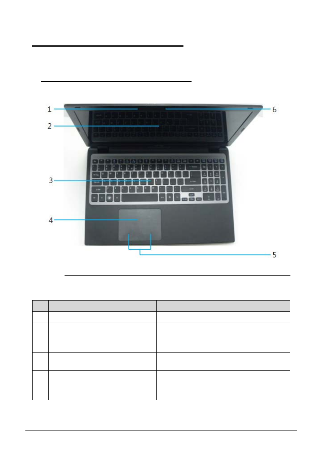
Open Top View 0
Figure 1-1. Open Top View
Table 1-1. Open Top View
No Icon Item Description
1 Microphone Internal microphone for recording sound.
2 Display screen Also called Liquid-Crystal Display (LCD),
displays computer output.
3 Keyboard For entering data into computer.
4 Touchpad Touch-sensitive pointing device which functions
like a computer mouse.
5 Click button area (left
and right)
6 Webcam Web camera for video communication.
Hardware Specifications and Configurations 1-11
The left and right button function like the left and
right mouse buttons.
Page 22

Closed Front View 0
Figure 1-2. Closed Front View
Table 1-2. Closed Front View
No Icon Item Description
1 Power button Turns the computer on and off.
2 Power indicator Indicates the computer’s power status.
3 Battery indicator Indicates the computer’s battery status.
Closed Rear View 0
Figure 1-3. Closed Rear View
Table 1-3. Closed Rear View
No Icon Item Description
1 Ventilation slots Enable the computer to stay cool, even after
prolonged use.
1-12 Hardware Specifications and Configurations
Page 23

Table 1-3. Closed Rear View
SS
No Icon Item Description
2 Headphones/
speaker/line-ou
t jack with
S/PDIF support
3 USB 2.0 port Connects to USB 2.0 devices (e.g., USB
4 USB 3.0 port Connects to USB devices. Supports the USB
5 HDMI port Supports high definition digital video
6 Ethernet
(RJ-45) port
7 DC-in jack Connects to an AC adapter.
Connects to audio line-out devices (e.g.,
speakers, headphones).
mouse, USB camera).
3.0 (SuperSpeed USB) specification.
connections.
Connects to an Ethernet 10/100/1000-based
network.
Left View 0
Figure 1-4. Left View
Table 1-4. Left View
No Icon Item Description
1 Optical drive Internal optical drive; accepts CDs DVDs.
2 Optical disk access
indicator
3 Optical drive eject button Ejects the optical disk from the drive.
Hardware Specifications and Configurations 1-13
Lights up when the optical drive is active.
Page 24

NOTE:
NOTE:
Table 1-4. Left View
No Icon Item Description
4 Emergency eject hole Ejects the optical drive tray when the computer is
turned off.
Insert a paper clip to the emergency eject hole
to eject the optical drive tray when the
computer is off.
5
Multi-in-1 card reader Accepts Secure Digital (SD 3.0), MultiMediaCard
(MMC).
Push to remove/install the card. Only one card
can operate at any given time.
Right View 0
Figure 1-5. Right View
Table 1-5. Right View
No Icon Item Description
1 Kensington lock slot Connects to a Kensington-compatible computer
security lock.
Wrap the computer security lock cable around an
immovable object such as a table or handle of a
locked drawer. Insert the lock into the notch and turn
the key to secure the lock. Some keyless models are
also available.
1-14 Hardware Specifications and Configurations
Page 25

Base View 0
Figure 1-6. Base View
Table 1-6. Base View
No Icon Item Description
1 Main door
2 Speakers Deliver stereo audio output.
Houses the computer’s HDD, Memory bar, SSD card
and WLAN card.
Hardware Specifications and Configurations 1-15
Page 26

Indicators 0
The computer has two easy-to-read status indicators. The following indicators are visible
even when the computer cover is closed.
Table 1-7. Indicators
Icon Function Description
Power indicator Indicates the computer’s power status.
Battery indicator Indicates the computer’s battery status.
Touchpad Basics 0
Figure 1-7. Touchpad
Move finger across the TouchPad (1) to move the cursor.
Press the left (2) and right (3) buttons located beneath the TouchPad to perform selection and
execution functions. These two virtual buttons are the equivalent of the left and right buttons on a
mouse. Tapping on the TouchPad is the same as clicking the left button.
Table 1-8. Touchpad
Function Left Button (2) Right Button (3) Main Touchpad (1)
Execute Quickly click twice. Rapidly tap twice.
1-16 Hardware Specifications and Configurations
Page 27

Table 1-8. Touchpad
Function Left Button (2) Right Button (3) Main Touchpad (1)
Select Click once. Tap once.
Access context
menu
Click once.
Using the Keyboard 0
The keyboard contains an embedded numeric keypad, a separate cursor, windows key, lock
function keys, special and full sized keys.
Figure 1-8. Keyboard Lock Keys
Hardware Specifications and Configurations 1-17
Page 28

Lock Keys 0
The keyboard has three lock keys which the user can toggle on and off.
Table 1-9. Lock Keys
Lock key Description
Caps Lock When on, all alphabetic characters are in uppercase.
Num Lock Off by default. When On, internal keyboard acts as numeric key padlock. If an
external keyboard or keypad is present, the Num Lock will have the following
definitions:
When On, the system boots with external keyboard/keypad Num Lock
status On. Internal keyboard overlay numeric keys are disabled.
The key can be turned on/off via the internal keyboard (Fn+F11) or the
external keyboard/keypad. Num Lock affects the external keyboard/keypad
only.
Shift state is NOT used for the cursor movement by the numeric keys.
The state of the Num Lock is not changed by the attachment/removal (hot
plug) of the external keyboard/keypad.
Scroll Lock
<Fn> +<F12>
When On, the screen moves one line up or down when pressing up or down
arrow keys. Scroll Lock is not applicable for all applications.
1-18 Hardware Specifications and Configurations
Page 29

Windows Keys 0
The keyboard has two keys that perform Windows-specific functions.
Windows Logo key
Application key
Table 1-10. Windows Keys
Key Description
Windows Logo
key
Pressed alone, this key has the same effect as clicking on the Windows Start
button; it launches the Start menu. It can also be used with other keys to
provide a variety of functions.
Functions supported by Windows XP, Windows Vista, and Windows 7:
< >: Open or close the Start menu
< > + <R>: Open the Run dialog box
< > + <M>: Minimizes all windows
<SHIFT> + < > + M: Undo minimize all windows
< > + <F1>: Show the help window
< > + <E>: Open Windows Explorer
< > + <F>: Search for a file or folder
< > + <D>: Show the desktop
<CTRL> + < > + <F>: Search for computers (search in network)
< > + <L>: Lock computer (if connected to a network domain), or switch
users (if not connected to a network domain)
<CTRL> + < > + <TAB>: Moves focus from Start menu, to the Quick
Launch toolbar, to the system tray (use RIGHT ARROW or LEFT ARROW to
move focus to items on the Quick Launch toolbar and the system tray)
< > + <TAB>: Cycle through programs on the taskbar
< > + <BREAK>: Display the System Properties dialog box
Functions supported by Windows XP:
< > + <BREAK>: Show the System Properties dialog box
< > + <U>: Open Ease of Access Center
Application key This key has the same effect as clicking the right mouse button; opening the
application's context menu.
Hardware Specifications and Configurations 1-19
Page 30

Hotkeys 0
The computer uses hotkeys or key combinations to access most computer controls.
To activate hotkeys, press and hold the <Fn> key before pressing the key in the combination.
Figure 1-9. Keyboard Hotkeys
Table 1-11. Hotkeys
Hotkey Icon Function Description
<Fn> + <F3> Communication
Device On/Off
<Fn> + <F4> Sleep Puts the computer in Sleep mode.
<Fn> + <F5> Display toggle Switches display output between the display
<Fn> + <F6> Display off Turns Off the LCD back light
<Fn> + <F7> Touchpad
toggle
<Fn> + <F8> Speaker toggle Turns the speakers On and Off.
<Fn> + <> Brightness Up Increases the screen brightness.
<Fn> + <> Brightness
Down
<Fn> +<Home> Play/Pause Play or pause a selected media file.
<Fn> + <Pg Up> Stop Stop playing the selected media file.
Toggles WiFi, 3G and Bluetooth On and Off
using a pop-up window.
screen, external monitor (if connected) and
both.
Turns the touchpad On and Off.
Decreases the screen brightness.
<Fn> +<Pg Dn> Previous Return to the previous media
<Fn> + <End> Next Jump to the next media file.
1-20 Hardware Specifications and Configurations
Page 31

Table 1-11. Hotkeys (Continued)
Hotkey Icon Function Description
Alt> + <F10> D2D recovery Enters to the D2D recovery during POST
Hardware Specifications and Configurations 1-21
Page 32

System Block Diagram
1-22 Hardware Specifications and Configurations
Page 33

Specification Tables 0
NOTE:
Computer specifications
Item Metric Imperial
Dimensions
Length 376.4 mm 14.81 in
Width 253.0 mm 10.0 in
Height
(front/rear)
Weight (equipped with optical
drive, flash drive, and battery)
Input power
Operating voltage 19V at 3.42A Max for 65W
Operating current 3.42A(Max)
Temperature
Operating (not writing to
optical disc)
Operating (writing to optical
disc)
Nonoperating -20°C to 60°C -4°F to 140°F
Relative humidity
Operating 10% to 90%
Nonoperating 5% to 95%
Maximum altitude (unpressurized)
19.7/20.7 mm 0.77/0.82 in
2.25 kg with HDD 4.5 lbs with HDD
0°C to 35°C 32°F to 95°F
5°C to 35°C 41°F to 95°F
Operating -15 m to 3,048 m -50 ft to 10,000 ft
Nonoperating -15 m to 12,192 m -50 ft to 40,000 ft
Shock
Operating 125 g, 2 ms, half-sine
Nonoperating 200 g, 2 ms, half-sine
Random vibration
Operating 0.75 g zero-to-peak, 10 Hz to 500 Hz, 0.25 oct/min sweep rate
Nonoperating 1.50 g zero-to-peak, 10 Hz to 500 Hz, 0.25 oct/min sweep rate
Applicable product safety standards specify thermal limits for plastic surfaces. The computer
operates within this range of temperatures.
Hardware Specifications and Configurations 1-23
Page 34

System Board Major Chips
Item Specification
Core logic Intel Panther Point HM77
VGA NVIDIA Optimus™ GeForce GT640M
LAN BCM57780
USB 3.0 RT9712AGS
Embedded controller NUVOTON NPCE795L
Bluetooth Atheros AR3012, Broadcom BCM20702
Wireless BCM943227HM4L
TPM NUVOTON NPCT420R(For future SKU)
PCMCIA N/A
Audio codec Realtek ALC271X
Card reader Realtek RTS5209
Processor
Item Specification
Central Processing Unit
®
Intel
Sandy Bridge Core i7/i5/i3 Processor
(CPU) type
CPU package FC-BGA 1023
Core Logic Multi execution cores·
A 32-KB instruction and 32-KB data first-level cache (L1) for
each core
A 256-KB shared instruction/data second-level cache (L2) for
each core
Up to 4-MB shared instruction/data third-level cache (L3),
shared among all cores
Chipset
Mobile Intel
®
HM77
Processor Specifications
Item CPU Sp eed
Cores Mfg Tech Cache Size Package
(GHz)
i7-2637M 1.7 4 32 nm 4 MB BGA 1023
i5-2467M 1.6 2 32 nm 3 MB BGA 1023
i3-2367M 1.4 2 32 nm 3 MB BGA 1023
1-24 Hardware Specifications and Configurations
Page 35

CPU Fan True Value Table
CPU
Fan Speed (RPM) SPL Spec (dBA)
Temperature
50 2600 28
58 3000 31
66 3300 34
74 3700 37
85 4000 40
Throttling 50%: On= 95 °C; OFF=80 °C
OS shut down at 100C; H/W shut down at 92 °C
System Memory
Item Specification
Memory controller Built in CPU
Memory size 2GB DDR3 RAM on-board+one DDR3 DIMM socket
DIMM socket number 1
Supports memory size per
2/4GB
socket
Supports maximum memory
6GB
size
Supports DIMM type Support DDR III 1333/1600MHz
SDRAM memory interface design
Supports DIMM Speed 1333/1600MHz
Support DIMM voltage 1.5V
Supports DIMM package 204P
Memory Combinations
On-board (MB) Slot (MB) Total Memory (MB)
2048 0 2048
2048 2048 4096
2048 4096 6144
Hardware Specifications and Configurations 1-25
Page 36

Graphics Controller
Item Specification
VGA Chip NVIDIA Optimus™ Geforce GT640M
Supports
®
CUDA
OpenGL
, PhysX®, 3D Vision®, Microsoft® DirectX® 11,
®
4.1, OpenCL™ 1.1
Video Interface
Item Specification
Chipset NVIDIA Optimus™ Geforce GT640M
Package 29mmx29mm
Interface LVDS
Compatibility 32bpp
Sampling rate 60Hz
BIOS
Item Specification
BIOS vendor Insyde
BIOS Type UEFI
BIOS ROM type W25Q32BV, W25Q16CV
BIOS ROM size 4MB
BIOS Features
Winbond code base
Flash ROM 4 MB
Support Acer UI
Support multi-boot
Suspend to RAM (S3)/Disk (S4)
Various hotkeys for system control
Support SMBIOS 2.3 ,PCI2.2.
DMI utility for BIOS serial number configurable/asset tag-
Support PXE
Support WinFlash
Wake on LAN from S3
Wake on LAN from S5 in AC mode
System information
Refer to Acer BIOS specification.
LAN Interface
Item Specification
LAN Chipset BROADCOM BCM57780
LAN connector type RJ45
1-26 Hardware Specifications and Configurations
Page 37

Item Specification
LAN connector location RJ45 at the rear side
Features Supports 10/100/1000Mbps
Keyboard
Item Specification
Type AF7S keyboard
Total number of keypads 103-US/104-UK/107-JP keys
Windows logo key Yes
Internal & external keyboard
Plug USB keyboard to the USB port directly: Yes
work simultaneously
Features
Phantom key auto detect
Overlay numeric keypad
Support independent pgdn/pgup/home/end keys
Support reverse T cursor keys
Factory configurable different languages by OEM customer
Hard Disk Drive (AVL components)
Item Specification
Vendor & Model
Name
Capacity (GB)
HITACHI
HTS545050A7E380
HITACHI
HTS543232A7A384
SEAGATE
ST320LT020
500 320 320
Bytes per sector 4096 512 4096
Data heads 2 2 2
Drive Format
Height(mm) 7.0 7.0 7.0
Disks 1 1 1
Performance Specifications
Spindle speed (RPM) 5400 5400 5400
Buffer size 8MB 8MB 8MB
Interface SATA SATA SATA
Fast data transfer rate
3.0 3.0 3.0
(Gbits/s, max)
DC Power Requirement
Voltage tolerance 5V +/- 5% 5V +/- 5% 5V +/- 5%
Hardware Specifications and Configurations 1-27
Page 38

Solid State Drive (AVL components)
Item Specifications
Vendor &
Model Name
Capacity (GB) 128 256
Flash mode MLC MLC
Performance
Sequential Read (MB/s) 470 460
Sequential Write (MB/s) 180 360
Interface mSATA mSATA
Max. fast data transfer rate
(Gbits/s)
Operating Shock 1,500G/1.0ms 1,500G/1.0ms
DC Power Requirement
Voltage tolerance 3.3V +/- 5% 3.3V +/- 5%
Super-Multi Drive Interface
Item Specification
Vendor & Model name HITACHI-LG Slim DVD Super Multi Drive GU61N
LITEON LMT-128M3M LITEON LMT-256M3M
6.0 6.0
Performance Specification With CD Diskette With DVD Diskette
Transfer rate (KB/sec) Sustained: 3600(24x)Max Sustained: 11080(8x)Max
Buffer Memory 1MB
Interface SATA
1-28 Hardware Specifications and Configurations
Page 39

Item Specification
Applicable disc format Applicable disc format CD: CD-DA, CD-ROM, CD-ROM XA,
Photo CD (multi-session), Video CD, Cd-Extra (CD+), CD-text
DVD: DVD-VIDEO, DVD-ROM, DVD-R (3.9GB, 4.7GB)
DVD-R DL, DVD-RW, DVD-RAM, DVD+R, DVD+R DL,
DVD+RW CD: CD-DA (Red Book) - Standard Audio CD &
CD-TEXT CD-ROM (Yellow Book Mode1 & 2) - Standard Data
CD-ROM XA (Mode2 Form1 & 2) - Photo CD, Multi-Session
CD-I (Green Book, Mode2 Form1 & 2, Ready, Bridge)
CD-Extra/ CD-Plus (Blue Book) - Audio & Text/Video Video-CD
(White Book) - MPEG1 Video CD-R (Orange Book Part)
CD-RW & HSRW (Orange Book Part Volume1 & Volume 2
Super Audio CD (SACD) Hybrid type US & US+ RW DVD:
DVD-ROM (Book 1.02), DVD-Dual DVD-Video (Book 1.1)
DVD-R (Book 1.0, 3.9G) DVD-R (Book 2.0, 4.7G) - General &
Authoring DVD+R (Version 1.0) DVD+RW DVD-RW (Non
CPRM & CPRM) DVD+/-R Dual
Loading mechanism Load: Manual Release: (a) Electrical Release (Release Button)
(b) Release by ATAPI command (c) Emergency Release
Power Requirement
Input Voltage 5 V +/- 5% (Operating)
LED 15.6”
Item Specification
Vendor/model name AUO 15.6”HD 16:9 Color TFT-LCD/ B156XTN03.0
Screen Diagonal (mm) 394.9(15.55in)
Active Area (mm) 344.2 X 193.5
Display resolution (pixels) 1366x3(RGB)x768
Pixel Pitch (mm) 0.252x0.252
Typical White Luminance
200 typ.170 min
(cd/m2) also called
Brightness
Contrast Ratio 500 typ.
Response Time (Optical Rise
8 typ. / 16 Max
Time/Fall Time) msec
Typical Power Consumption
3.4 max
(watt)
Weight (without inverter) 400g max
Physical Size (mm) 360 x 224.3 x 3.4 max
Electrical Interface 1 channel LVDS
Hardware Specifications and Configurations 1-29
Page 40

Item Specification
Viewing Angle
(degree)Horizontal (Right) CR
= 10 (Left)Vertical (Upper) CR
= 10 (Lower)
Display Supported Resolution (LCD Supported Resolution)
Resolution 16 bits 32 bits Intel NVIDIA
800x600p/60Hz 16:9 Y Y Y Y
1024x768p/60Hz 16:9 Y Y Y Y
1280x600/60Hz 16:9 Y Y Y Y
1280x720/60Hz 16:9 Y Y Y Y
1280x768/60Hz 16:9 Y Y Y Y
1360x768/60Hz 16:9 Y Y Y Y
1366x768/60Hz 16:9 Y Y Y Y
Graphics Controller
Item Specification
VGA Chip NVIDIA Optimus™ GeForce GT640M with dedicated DDR3
45 (Right) / 45 (Left) / 15 (Upper) / 35 (Lower)
VRAM
Supports CUDA®, PhysX®, 3D Vision®, Microsoft® DirectX® 11,
OpenGL® 4.1, OpenCL™ 1.1
Display Supported Resolution (GPU Supported Resolution)
Resolution 16 bits 32 bits Intel NVIDIA
800x600p/60Hz 16:9 Y Y Y Y
1024x768p/60Hz 16:9 Y Y Y Y
1280x600/60Hz 16:9 Y Y Y Y
1280x720/60Hz 16:9 Y Y Y Y
1280x768/60Hz 16:9 Y Y Y Y
1360x768/60Hz 16:9 Y Y Y Y
1366x768/60Hz 16:9 Y Y Y Y
Display Supported Resolution (LCD panel Supported Resolution)
Resolution 16 bits 32 bits Intel NVIDIA
800x600p/60Hz 16:9 Y Y Y Y
1024x768p/60Hz 16:9 Y Y Y Y
1280x600/60Hz 16:9 Y Y Y Y
1-30 Hardware Specifications and Configurations
Page 41

Resolution 16 bits 32 bits Intel NVIDIA
1280x720/60Hz 16:9 Y Y Y Y
1280x768/60Hz 16:9 Y Y Y Y
1360x768/60Hz 16:9 Y Y Y Y
1366x768/60Hz 16:9 Y Y Y Y
Bluetooth Interface
Item Specification
Chipset Atheros AR3012, Broadcom BCM20702
Data throughput
TX 1.2Mbits/sec
RX 1.2Mbits/sec
Protocol 4.0+HS
Interface USB 2.0
Connector type
SM08B-SURS-TF/JST
SM06B-XSRK-ETB/SM08B-SURS-TF
Supported protocol A2DP
Bluetooth Module
Item Specifications
Controller Atheros AR3012, Broadcom BCM20702
Features
Mini USB module with built-in antenna
Bluetooth 4.0
Camera
Item Specification
Vendor and Model PRIMAX 50-70511ARC8
Type 1.3M
WIFI Card
Item Specification
Vendor and Model FOXCONN T77H167 LITEON WN6603AH
Wireless LAN Standards 802.11b/g/n
Operating Frequency 2.4 GHz
Form Factor Half-Mini card
Host Interface PCI-Express Bus interface
PCB 4-layer design and single side
Antenna connector 2UFL type
Hardware Specifications and Configurations 1-31
Page 42

Audio Codec and Amplifier
Item Specification
Audio Controller Realtek ALC271X
1-32 Hardware Specifications and Configurations
Page 43

Item Specification
Features Meets Microsoft WLP (Windows Logo Program) audio
requirements
High performance DACs with digital >110dB and analog
98dB (A-weighting) signal-to-noise
High performance ADCs with digital > 100dB and analog
90dB (A-Weighting) signal-to-noise ratio
Six DAC channels support 16/20/24-bit PCM format for 5.1
sound playback
Two stereo ADCs support 16/20/24-bit PCM format, multiple
stereo recording
All DACs supports 44.1k/48k/96k/192kHz sample rate
Primary 16/20/24-bit SPDIF-OUT supports
32k/44.1k/48k/88.2k/96k/192kHz sample rate
Secondary 16/20/24-bit SPDIF-OUT supports
32k/44.1k/48k/88.2k/96k/192kHz sample rate
Analog jacks (port-A, B, C, E and G) support stereo input and
output re-tasking
Support MONO output at port-H
Port-A/D/E/F built in headphone amplifiers
Port-E and Port-F headphone amplifiers can drive earphone
directly without DC blocking capacitor
Port-B/C/E/F with software selectable boost gain
(+10/+20/+30dB) for analog microphone input
Supports external PCBEEP input and built-in digital BEEP
generator
Software selectable 2.5V/3.2V VREFOUT
Supports legacy analog mixer architecture
Four channels of digital microphone array input for voice
applications
Two jack detection pins each designed to detect up to 4 jacks
plugging
1.0dB/step playback volume control
1.5dB/step recording volume control
High pass filter to cancel DC offset from AD converter
Jack detection function is supported when device is in power
down mode (D3)
2 GPIOs (General Purpose Input and Output) for customized
applications. GPIO0 and GPIO1 share pin with digital
microphone
Supports anti-pop mode when analog power AVDD is on and
digital power is off
Intel low power ECR compliant and power status control for
every analog converter and pin widgets
Supports 3.3V digital core power, 1.5V~ 3.3V scalable digital
I/O power for HD Audio link, and
3.0~5.0V analog power
48-pin LQFP 'Green' package
Hardware Specifications and Configurations 1-33
Page 44

Item Specification
Amplifier Embedded
Features
4 step gain control
2-W/Ch Output Power into 3-W load from 5-V supply
Fully Differential Input
Low Supply Current and Shutdown selection
Embedded de-pop circuit
Audio Interface
Item Specification
Audio Controller Realtek ALC271X
Audio onboard or optional On board
Mono or Stereo Stereo
Resolution Support 16/20/24bit PCM
Compatibility HD audio Interface;
Sampling rate Sample rate up to 192Khz resolution VSR (Variable Sampling
Rate)
Internal microphone Yes
Internal speaker/quantity Yes/(2W speaker x1)
Battery
Item Specifications
Vendor & Model name SANYO UPF656790
Battery Type Lithium polymer
Pack capacity 4850 mAh
Number of battery cell 3
Package configuration 3S1P
VRAM
Item Specification
Chipset
HYNIX H5TQ1G63DFR-11C
Memory size 1GB
Interface DDR3
USB Port
Item Specification
USB compliance level USB3.0, USB2.0
1-34 Hardware Specifications and Configurations
Page 45

Item Specification
EHCI 2
Number of USB port(s) USB3.0x1, USB2.0x2
Location USB3.0 at the rear side
USB2.0 two at the rear side
Output Current 1.0A for each connector
HDMI Port
Item Specification
Compliance level HDMI1.3c
Data thoroughput Up to 16.7 million colors
Number of HDMI port(s) 1
Location HDMI at the rear side
AC Adapter
Item Specification
Input rating 100-240V AC
Maximum input AC current 1.5A Max at 100V AC
Inrush current No damage; meet fuse and bridge diode.
Efficiency 84% min. at nominal input voltage.
System Power Management
Item Specification
Mech. Off (G3) All devices in the system are turned off completely.
Soft Off (G2/S5) OS initiated shutdown. All devices in the system are turned off
completely.
Working (G0/S0) Individual devices like CPU and hard disc can be power
managed.
Suspend to RAM (S3) CPU set power down, VGA Suspend, PCMCIA SuspendAudio,
Power Down, Hard Disk Power Down, CD-ROM Power Down,
Super I/O Low Power mode.
Save to Disk (S4) Also called Hibernation Mode. System saves all system states
and data onto the disc prior to power off the whole system.
Card Reader
Item Specification
Chipset REALTEK RTS5209 PCIe card reader controller
Package 48-pin LQFP
Hardware Specifications and Configurations 1-35
Page 46

Item Specification
Maximum supported size SD: 2T, MMC: 16G, miniSD: 16G
Features Supports SD Extended Capacity (SDXC), compliant with the
SD Memory Card Specification Version 3.0.
System LED Indicator
Item Specification
Power indicator
Blue color solid on: System on
Blue color and amber color off: System off
Amber color blinking: S3 state
Battery indicator Charging
Amber solid on - Battery charging with AC
Blue color solid on - Battery full
Amber blinking - Battery abnormal stop charge or batter in
low power state
Discharging
Amber and blinking - Battery in critical low state
Amber color off - Discharging state.
System DMA Specification
Hardware DMA System Function
DMA0 Not applicable
DMA1 Not applicable
DMA2 Not applicable
DMA3 Not applicable
DMA4 Direct memory access controller
DMA5 Not applicable
DMA6 Not Assigned
DMA7 Not Assigned
System Interrupt Specification
Hardware IRQ System function
IRQ00 System timer
IRQ01 Standard PS/2 Keyboard
IRQ08 System CMOS/real time clock
IRQ12 ELAN PS/2 Port Input Device
IRQ13 Numeric data processor
IRQ81 IRQ190 Microsoft ACPI-Compliant System
1-36 Hardware Specifications and Configurations
Page 47

Hardware IRQ System function
IRQ10 Intel(R) 7 Series/C216 Series Chipset Family SMBUS Host
Controller – 1E22
IRQ16 Intel(R) 7 Series/C216 Series Chipset Family USB Enhanced
Host Controller- 1E2D
Intel(R) 7 Series/C216 Series Chipset Family PCI Express Rott
Port2 – 1E12
Intel(R) 7 Management Engine Interface
NVIDIA GeForce GT 640M
XEON E3-1200/2
nd
Generation Intel(R) Core(TM) Processor
Family PCI Express Root Port - 0101
IRQ17 Atheros AR5B97 Wireless Network Adapter
Intel(R) 7 Series/C216 Series Chipset Family PCI Express Rott
Port1 – 1E10
IRQ19 Intel(R) 7 Series/C216 Series Chipset Family PCI Express Rott
Port4 – 1E16
Intel(R) Mobile Express Chipset SATA AHCI Controller
IRQ22 High Definition Audio Controller
IRQ23 Intel(R) 7 Series/C216 Series Chipset Family USB Enhanced
Host Controller
- 1E26
IRQ-5 Broadcom Netlink (TM) Gigibit Ethernet
IRQ-3 Intel(R) USB 3.0 eXtensible Host Controller
IRQ-2 Intel(R) HD Graphics Family
System IO Address Map
I/O address (hex) System Function (shipping configuration)
0000 - 001F Direct memory access controller
0000 - 0CF7 PCI bus
0020 – 0021 Programmable interrupt controller
0024 – 0025 Programmable interrupt controller
0028 – 0029 Programmable interrupt controller
002C – 002D Programmable interrupt controller
002E – 002F Motherboard resources
0030 – 0031 Programmable interrupt controller
0034 – 0035 Programmable interrupt controller
0038 – 0039 Programmable interrupt controller
003C – 003D Programmable interrupt controller
0040 – 0043 System timer
Hardware Specifications and Configurations 1-37
Page 48

I/O address (hex) System Function (shipping configuration)
004E – 004F Motherboard resources
0050 – 0053 System timer
0060 – 0060 Standard PS/2 Keyboard
0061 – 0061 Motherboard resources
0062 – 0062 Microsoft ACPI-Compliant Embedded Controller
0063 – 0063 Motherboard resources
0064 – 0064 Standard PS/2 Keyboard
0065 – 0065 Motherboard resources
0066 – 0066 Microsoft ACPI-Compliant Embedded Controller
0067 – 0067 Motherboard resources
0070 – 0070 Motherboard resources
0070 – 0077 System CMOS/real time clock
0080 – 0080 Motherboard resources
0081 - 0091 Direct memory access controller
0092 – 0092 Motherboard resources
0093 – 009F Direct memory access controller
00A0 – 00A1 Programmable interrupt controller
00A4 – 00A5 Programmable interrupt controller
00A8 – 00A9 Programmable interrupt controller
00AC – 00AD Programmable interrupt controller
00B0 – 00B1 Programmable interrupt controller
00B2 – 00B3 Motherboard resources
00B4 – 00B5 Programmable interrupt controller
00B8 – 00B9 Programmable interrupt controller
00BC – 00BD Programmable interrupt controller
00C0 – 00DF Direct memory access controller
00F0 – 00F0 Numeric data processor
03B0 – 03BB Intel(R) HD Graphics Family
03C0 – 03DF Intel(R) HD Graphics Family
0400 – 00B3 Motherboard resources
0454 – 0457 Motherboard resources
0458 – 047F Motherboard resources
04D0 – 00B9 Programmable interrupt controller
1-38 Hardware Specifications and Configurations
Page 49

I/O address (hex) System Function (shipping configuration)
0500 – 057F Motherboard resources
0680 – 069F Motherboard resources
0D00 - FFFF PCI bus
1000 – 100F Motherboard resources
164E – 164F Motherboard resources
2000 – 2FFF Intel(R) 7 Series/C216 Chipset Family PCI Express Root Port1
– 1E10
3000 – 3FFF
XEON E3-1200/2
nd
Generation Intel(R) Core(TM) Processor
Family PCI Express
Root Port 1 - 0101
3F80 – 3FFF NVIDIA GeForce GT 640M
4000 – 403F Intel(R) HD Graphics Family
4040 – 405F Intel(R) 7 Series/C216 Series Chipset Family SMBUS Host
Controller – 1E22
4060 – 407F Intel(R) 7 Series Chipset Family SATA AHCI Controller
4080 – 4087 Intel(R) 7 Series Chipset Family SATA AHCI Controller
4088 – 408F Intel(R) 7 Series Chipset Family SATA AHCI Controller
4090 – 4093 Intel(R) 7 Series Chipset Family SATA AHCI Controller
4094 – 4097 Intel(R) 7 Series Chipset Family SATA AHCI Controller
0FFF – 0FFF Motherboard resources
0FFF – 0FFF Motherboard resources
Hardware Specifications and Configurations 1-39
Page 50

1-40 Hardware Specifications and Configurations
Page 51

CHAPTER 2
System Utilities
Page 52

BIOS Setup Utility. . . . . . . . . . . . . . . . . . . . . . . . . . . . . . . . . . . . . 2-3
Navigating the BIOS Utility . . . . . . . . . . . . . . . . . . . . . . . . . . .2-3
BIOS . . . . . . . . . . . . . . . . . . . . . . . . . . . . . . . . . . . . . . . . . . . . . . . 2-4
Information. . . . . . . . . . . . . . . . . . . . . . . . . . . . . . . . . . . . . . . .2-4
Main . . . . . . . . . . . . . . . . . . . . . . . . . . . . . . . . . . . . . . . . . . . . . 2-6
Security . . . . . . . . . . . . . . . . . . . . . . . . . . . . . . . . . . . . . . . . . . .2-8
Boot. . . . . . . . . . . . . . . . . . . . . . . . . . . . . . . . . . . . . . . . . . . . . .2-12
Exit. . . . . . . . . . . . . . . . . . . . . . . . . . . . . . . . . . . . . . . . . . . . . . .2-13
BIOS Flash Utilities . . . . . . . . . . . . . . . . . . . . . . . . . . . . . . . . . . . . 2-14
DOS Flash Utility. . . . . . . . . . . . . . . . . . . . . . . . . . . . . . . . . . . .2-15
WinFlash Utility . . . . . . . . . . . . . . . . . . . . . . . . . . . . . . . . . . . .2-17
Remove HDD/BIOS Password Utilities. . . . . . . . . . . . . . . . . . . . . 2-18
Remove HDD Password Utilities . . . . . . . . . . . . . . . . . . . . . . . 2-18
Removing BIOS Passwords . . . . . . . . . . . . . . . . . . . . . . . . . . . .2-20
Cleaning BIOS Passwords . . . . . . . . . . . . . . . . . . . . . . . . . . . . .2-21
Using DMI Tools. . . . . . . . . . . . . . . . . . . . . . . . . . . . . . . . . . . . . . 2-22
LAN MAC EEPROM Utility . . . . . . . . . . . . . . . . . . . . . . . . . . . .2-29
2-2
Page 53

System Utilities
NOTE:
NOTE:
BIOS Setup Utility 0
A hardware configuration program built into a computer’s BIOS (Basic Input/Output System).
Preconfigured and optimized so users do not need to run this utility. If configuration problems
occur, users may need to run Setup. Refer to Chapter 4, Troubleshooting when problem
arises.
To activate the BIOS Utility, press F2 during POST when prompted at the bottom of screen.
The default parameter of F12 Boot Menu is set to disabled. To change boot device without
entering BIOS Setup Utility, set the parameter to enabled.
To change boot device without entering the BIOS SETUP, Press <F12> during POST to enter
multi-boot menu.
Navigating the BIOS Utility 0
Five menu options are:
Information
Main
Security
Boot
Exit
To navigate through the following:
Menu - use the left and right arrow keys
Item - use the up and down arrow keys
Change parameter value - press F5 or F6.
Exit - Press Esc
Load default settings - press F9. Press F10 to save changes and exit BIOS Setup Utility
Parameter values can be changed if enclosed in square brackets [ ]. Navigation keys
appear at the bottom of the screen. Read parameter help carefully when making
changes to parameter values. Parameter help is found in the Item Specific Help area of
the screen. System information is subject to specific models.
System Utilities 2-3
Page 54

BIOS 0
NOTE:
NOTE:
The following is a description of the tabs found on the InsydeH20 Setup Utility screen:
The screens provided are for reference only. Actual values may differ by model.
Information 0
This tab shows a summary of computer hardware information.
Figure 2-1. BIOS Information
2-4 System Utilities
Page 55

Table 2-1 describes the parameters shown in Figure 2-1
Table 2-1. Parameters
Parameter Description
CPU Type The CPU type and speed of the system.
CPU Speed The speed of the CPU.
HDD Model Name The model name of HDD installed on primary IDE master.
HDD Serial Number The serial number of HDD installed on primary IDE master.
ATAPI Model Name The model name of the installed ODD drive.
System BIOS
Displays system BIOS version.
Version
VGA BIOS Version The VGA firmware version of the system.
Serial Number The serial number of this unit.
Asset Tag Number The asset tag number of the system.
Product Name The product name of the system.
Manufacturer Name The manufacturer Name of the system
UUID Universally Unique Identifier (UUID) is an identifier standard used in
software construction, standardized by the Open Software Foundation
(OSF) as part of the Distributed Computing Environment (DCE).
System Utilities 2-5
Page 56

Main 0
This tab allows the user to set system time and date, enable or disable boot option and
enable or disable recovery.
Figure 2-2. BIOS Main
Table 2-2 describes the parameters shown in Figure 2-2.
Table 2-2. BIOS Main
Parameter Description Format/Option
System
Time
System
Date
Tot al
Memory
Video
Memory
2-6 System Utilities
Sets the system time. The hours are shown with
24-hour format.
Sets the system date. Format MM/DD/YYYY
Shows the total memory available. N/A
Shows the available memory for Video. N/A
Format: HH:MM:SS
(hour:minute:second)
(month/day/year)
Page 57

Table 2-2. (Continued)BIOS Main
Parameter Description Format/Option
Quiet Boot The notebook shows an illustration called the OEM
screen during system boot instead of the traditional
POST screen that shows the normal diagnostic
messages.
Network
Boot
F12 Boot
Enables, disables the system boot from LAN (remote
server).
Enables, disables Boot Menu during POST. Enabled or Disabled
Menu
D2D
Recovery
Enables, disables D2D Recovery function. The function
allows the user to create a hidden partition on hard disc
drive to store operation system and restore the system
to factory defaults.
SATA Mode Control the mode in which the SATA controller should
operate.
Enabled or Disabled
Enabled or Disabled
Enabled or Disabled
AHCI or IDE
System Utilities 2-7
Page 58

Security 0
NOTE:
This tab shows parameters that safeguard and protect the computer from unauthorized use.
Figure 2-3. BIOS Security
Table 2-3 describes the parameters shown in Figure 2-3.
Table 2-3. BIOS Security
Parameter Description Option
Supervisor
Password Is
User Password Is Shows the setting of the user password. Clear or
Set Supervisor
Password
Set User Password Press Enter to set the user password. When user password is set,
Set HDD Password Enter HDD Password. N/A
Password on Boot Defines whether a password is required or not while the events
Shows the setting of the supervisor password Clear or
Set
Set
Press Enter to set the supervisor password. When set, this
password protects the BIOS Setup Utility from unauthorized access.
The user can not either enter the Setup menu nor change the value
of parameters.
this password protects the BIOS Setup Utility from unauthorized
access. The user can enter Setup menu only and does not have right
to change the value of parameters.
defined in this group happened. The following sub-options are all
requires the Supervisor password for changes and should be grayed
out if the user password was used to enter setup.
N/A
N/A
Disabled
or
Enabled
When prompted to enter a password, three attempts are allowed before the system halts. Resetting
the BIOS password may require the computer be returned to the dealer.
2-8 System Utilities
Page 59

Setting a Password 0
IMPORTANT:
+
NOTE:
NOTE:
Perform the following to set the user or supervisor password:
1. Use the and keys to highlight the Set Supervisor Password parameter and press
Enter key. The Set Supervisor Password box appears.
Figure 2-4. Set Supervisor Password
2. Type a new password in the Enter New Password field. Password length is not to exceed
8 alphanumeric characters (A-Z, a-z, 0-9, not case sensitive). Retype the password in the
Confirm New Password field.
Use care when typing a password. Characters do not appear on the screen.
3. Press Enter. After setting the password, the computer sets the User Password parameter
to Set.
Users can opt to enable the Password on boot parameter.
4. Press F10 to save changes and exit the BIOS Setup Utility.
Removing a Password 0
Perform the following:
1. Use the and keys to highlight Set Supervisor Password and press Enter. The Set
Supervisor Password box appears:
Figure 2-5. Set Supervisor Password
2. Type the current password in the Enter Current Password field and press Enter.
3. Press Enter twice without typing anything in the Enter New Password and Confirm New
Password fields. The computer then sets the Supervisor Password parameter to Clear.
4. Press F10 to save changes and exit the BIOS Setup Utility.
System Utilities 2-9
Page 60

Changing a Password 0
NOTE:
NOTE:
1. Use the and keys to highlight Set Supervisor Password and press the Enter. The Set
Supervisor Password box appears.
Figure 2-6. Set Supervisor Password
2. Type the current password in the Enter Current Password field and press Enter.
3. Type a password in the Enter New Password field. Retype the password in the Confirm
New Password field.
Figure 2-7. Setup Notice
4. Press Enter. The computer sets User Password parameter to Set.
Users can enable the Password on boot parameter.
5. Press F10 to save changes and exit the BIOS Setup Utility.
If the verification is OK, the screen will show as following.
Figure 2-8. This Setup Warning
The password setting is complete after the user presses Enter.
If the current password entered does not match the actual current password, the screen will
show the Setup Warning (Figure 2-9).
2-10 System Utilities
Page 61

Figure 2-9. Setup Warning
System Utilities 2-11
Page 62

Boot 0
This tab allows changes to the order of boot devices used to load the operating system.
Bootable devices include the:
USB diskette drives
Onboard hard disk drive
DVD drive in the module bay
Use and keys to select a device and press F5 or F6 to move it up or down the list.
Figure 2-10. BIOS Boot
2-12 System Utilities
Page 63

Exit 0
The Exit tab allows users to save or discard changes and quit the BIOS Utility.
Figure 2-11. BIOS Exit
Table 2-4 describes the parameters in Figure 2-11.
Table 2-4. Exit Parameters
Parameter Description
Exit Saving Changes Exit System Setup and save changes to the system.
Exit Discarding Changes Exit utility without saving setup data to.
Load Setup Default Load default values for all setup item.
Discard Changes Load previous values all setup items.
Save Changes Save setup data.
System Utilities 2-13
Page 64

BIOS Flash Utilities 0
NOTE:
NOTE:
NOTE:
NOTE:
NOTE:
NOTE:
NOTE:
NOTE:
BIOS Flash memory updates are required for the following conditions:
New versions of system programs
New features or options
Restore a BIOS when it becomes corrupted.
Use the Flash utility to update the system BIOS Flash ROM.
Create a Crisis Recovery Disc, if one is not available, before the Flash utility is used.
Do not install memory related drivers (XMS, EMS, DPMI) when the Flash is used.
Use the AC adaptor power supply when running the Flash utility. If battery pack does
not contain power to finish loading of the BIOS Flash, do not boot the system.
Perform the following to run the Flash:
1. Prepare a bootable diskette.
2. Copy the Flash utilities to the bootable diskette.
3. Boot the system from the bootable diskette.
The Flash utility has auto execution function.
2-14 System Utilities
Page 65

DOS Flash Utility 0
Perform the following to use the DOS Flash Utility:
1. Press F2 during boot to enter the Setup Menu.
2. Select Boot Menu to modify the boot priority order.
Example: If using USB HDD to Update BIOS, move USB HDD to position 1.
Figure 2-12. BIOS Boot
3. Execute the < UPDATE.BAT > batch file to update BIOS. The flash process begins as
shown in Figure 2-13.
System Utilities 2-15
Page 66

Figure 2-13. DOS Flash
NOTE:
NOTE:
NOTE:
NOTE:
4. In flash BIOS, the message Please do not remove AC Power Source is shown.
If AC power is not connected, the following message (Figure 2-14) is shown.
Figure 2-14. AC Power Warning
Plug in the AC power to continue.
5. Flash is complete when the message Flash Programming Complete is shown.
2-16 System Utilities
Page 67

WinFlash Utility 0
Perform the following to use the WinFlash Utility:
1. Double click the WinFlash executable.
2. Click OK to begin the update. A progress screen is shown (Figure 2-15).
Figure 2-15. InsydeFlash
System Utilities 2-17
Page 68

Remove HDD/BIOS Password Utilities 0
NOTE:
NOTE:
NOTE:
NOTE:
This section provides details for removing HDD/BIOS passwords.
Remove HDD Password Utilities 0
This section provides details for removing HDD passwords.
Remove HDD Password as follows:
If the HDD password is incorrectly entered three times, an error is generated, you will
see below menu (Figure 2-16).
Figure 2-16. HDD Security
To reset the HDD password, perform the followings:
1. Select Enter Unlock Password option.
Figure 2-17. Select Item
An Encode key is generated for unlocking utilities. Make note if this key.
Figure 2-18. Unlock Password
2. Execute the UnlockHD.EXE file to create the unlock code in DOS Mode using the format
<UnlockHD [Encode code] > with the code noted in the previous step.
Example: UnlockHD 84756887
The command generates a password which can be used for unlocking the HDD.
2-18 System Utilities
Password: 38534209
Page 69

Enter the password from the Step 1 to unlock the HDD (Figure 2-19).
NOTE:
NOTE:
Figure 2-19. Unlock Password
After customer clearing the HDD password, HDD maybe in “Frozen” state. Please
power off system. Then, power on to Win system, HDD Password will be in normal.
Figure 2-20. HDD Password Frozen
System Utilities 2-19
Page 70

Removing BIOS Passwords 0
To clear User or Supervisor passwords, open the DIMM door and use a metal instrument to
short the RTCRST# point.(Figure 2-21 and Figure 2-22)
Figure 2-21. CMOS Jumper
Figure 2-22. CMOS Jumper
r
2-20 System Utilities
Page 71

Cleaning BIOS Passwords 0
NOTE:
NOTE:
When customer forgets the BIOS supervisor/user password, he could clear the password as
below:
1. Prepare a USB flash disk with FAT32 file system and copy Disablepassword.efi file to root
directory.
2. After pressing power button, to hold Ctrl and Alt key and then continually stroke Enter key
until POST LOGO finish.
3. System will display “Press Y or y key to clear BIOS password.”.
4. After press Y/y key, BIOS will clear BIOS password and reboot system.
Figure 2-23. Clear BIOS Password
The on screen message indicates the function success.
This document is for Pegatron Acer project in 2012.
System Utilities 2-21
Page 72

Using DMI Tools 0
The DMI (Desktop Management Interface) Tool copies BIOS information to EEPROM. Used
in the DMI pool for hardware management.
1. Execute < MN.bat > to update SMBIOS Type 1 Manufacturer Name(Figure 2-23).
Figure 2-24. Manufacture Name
2-22 System Utilities
Page 73

2. Execute < PN.bat > to update SMBIOS Type 1 Product Name(Figure 2-24).
Figure 2-25. Update Product Name
System Utilities 2-23
Page 74

3. Execute < SN.bat > to update SMBIOS Type 1 Serial Number(Figure 2-25).
Figure 2-26. Update Serial Number
2-24 System Utilities
Page 75

4. Execute < AT.bat > to update SMBIOS Type 3 Asset Tag Number(Figure 2-26).
Figure 2-27. Update Asset Tag
System Utilities 2-25
Page 76

5. Execute < RU.bat > to read SMBIOS Type 1 UUID(Figure 2-27).
Figure 2-28. Read UUID
2-26 System Utilities
Page 77

6. Execute < WU.bat > to write SMBIOS Type 1 UUID(Figure 2-28).
Figure 2-29. Write UUID
System Utilities 2-27
Page 78

7. Execute < GU.bat > to generate and write SMBIOS Type 1 UUID (Figure 2-29).
Figure 2-30. Generate and write UUID
2-28 System Utilities
Page 79

LAN MAC EEPROM Utility 0
LAN EEPROM Utility enables to change the MAC address.
Perfer the following steps to use the LAN EEPROM Utility:
1. Create a DOS bootable USB HDD.
2. Copy the AN MAC EEPROM Utility to the HDD and remove the HDD form the computer.
3. Reboot the computer and press F2 during the boot sequence to enter the setup menu.
4. Select the Boot menu item and move the entry “USB HDD” to the first position. Refer to
Boot.
5. Insert the USB HDD and reboot the computer.
6. At the command prompt, navigate to the C Root folder.
7. Run B57diag –b57eng(Figure 2-31).
Figure 2-31. Execute MAC TOOL
System Utilities 2-29
Page 80

8. Enter Broadcom utility screen, then key in “secfg” command to show configuration screen.
Figure 2-32. Broadcom utility screen
9. Enter configuration
Figure 2-33. Configuration Screen
2-30 System Utilities
Page 81

10. You can see the current MAC address in item1 and key in “1” to edit MAC address
Figure 2-34. Edit MAC address
11. The new MAC address had changed in item1
Figure 2-35. MAC address Changed
System Utilities 2-31
Page 82

12. Key in “x” key to save and exit configuration
Figure 2-36. Exit configuration
2-32 System Utilities
Page 83

13. Key in “q” to exit Broadcom program
Figure 2-37. Exit Broadcom program
System Utilities 2-33
Page 84

2-34 System Utilities
Page 85

CHAPTER 3
Machine Maintenance
Page 86

Machine Disassembly and Replacement . . . . . . . . . . . . . . . . . 3-5
Recommended Equipment . . . . . . . . . . . . . . . . . . . . . . . . . . . 3-5
Replacement Requirements . . . . . . . . . . . . . . . . . . . . . . . . . . 3-5
Pre-disassembly Instructions. . . . . . . . . . . . . . . . . . . . . . . . . . 3-6
Disassembly Process . . . . . . . . . . . . . . . . . . . . . . . . . . . . . . . 3-7
External Module Disassembly Process . . . . . . . . . . . . . . . . . . 3-8
External Modules Disassembly Flowchart . . . . . . . . . . . . . . . . 3-8
Removing the Dummy Card . . . . . . . . . . . . . . . . . . . . . . . . . . 3-9
Removing the HDD Door . . . . . . . . . . . . . . . . . . . . . . . . . . . . . 3-10
Removing the HDD Module . . . . . . . . . . . . . . . . . . . . . . . . . . . 3-11
Removing the DIMM Module . . . . . . . . . . . . . . . . . . . . . . . . . . 3-12
Removing the SSD Module . . . . . . . . . . . . . . . . . . . . . . . . . . . 3-13
Removing the WLAN Module . . . . . . . . . . . . . . . . . . . . . . . . . 3-14
Removing the ODD Module. . . . . . . . . . . . . . . . . . . . . . . . . . . 3-16
Main Unit Disassembly Process . . . . . . . . . . . . . . . . . . . . . . . . 3-19
Main Unit Disassembly Flowchart . . . . . . . . . . . . . . . . . . . . . . 3-19
Removing the Top Case . . . . . . . . . . . . . . . . . . . . . . . . . . . . . 3-20
Removing battery. . . . . . . . . . . . . . . . . . . . . . . . . . . . . . . . . . . 3-26
Removing the Power switch board . . . . . . . . . . . . . . . . . . . . . 3-29
Remove the card reader . . . . . . . . . . . . . . . . . . . . . . . . . . . . . 3-30
Remove the cables from the Mainboard . . . . . . . . . . . . . . . . . 3-31
Removing the Mainboard. . . . . . . . . . . . . . . . . . . . . . . . . . . . . 3-34
Removing the Thermal module . . . . . . . . . . . . . . . . . . . . . . . . 3-36
Removing the Bluetooth Board . . . . . . . . . . . . . . . . . . . . . . . . 3-38
Removing the Speakers . . . . . . . . . . . . . . . . . . . . . . . . . . . . . 3-39
LCD Module Disassembly Process. . . . . . . . . . . . . . . . . . . . . . 3-41
LCD Module Disassembly Flowchart. . . . . . . . . . . . . . . . . . . . 3-41
Removing the LCD Bezel . . . . . . . . . . . . . . . . . . . . . . . . . . . . 3-42
Removing the LCD Panel . . . . . . . . . . . . . . . . . . . . . . . . . . . . 3-46
Removing the Camera Board . . . . . . . . . . . . . . . . . . . . . . . . . 3-48
LCD Reassembly Procedure . . . . . . . . . . . . . . . . . . . . . . . . . . . 3-49
Replacing the Camera. . . . . . . . . . . . . . . . . . . . . . . . . . . . . . . 3-49
Replacing the LCD Panel . . . . . . . . . . . . . . . . . . . . . . . . . . . . 3-50
Replacing the LCD Bezel. . . . . . . . . . . . . . . . . . . . . . . . . . . . . 3-52
Replacing the Bluetooth. . . . . . . . . . . . . . . . . . . . . . . . . . . . . . 3-53
Replacing the Speakers. . . . . . . . . . . . . . . . . . . . . . . . . . . . . . 3-54
Replacing the DC-IN cable . . . . . . . . . . . . . . . . . . . . . . . . . . . 3-56
Replacing the Thermal Module . . . . . . . . . . . . . . . . . . . . . . . . 3-57
Replacing the Mainboard. . . . . . . . . . . . . . . . . . . . . . . . . . . . . 3-59
Replacing the LCD Module & Cables to Mainboard . . . . . . . . 3-60
3-2
Page 87

Replacing the Card reader. . . . . . . . . . . . . . . . . . . . . . . . . . . . 3-63
Replacing the Power Switch board&Battery . . . . . . . . . . . . . . 3-64
Replacing the Keyboard . . . . . . . . . . . . . . . . . . . . . . . . . . . . . 3-67
Replacing the ODD Module . . . . . . . . . . . . . . . . . . . . . . . . . . . 3-73
Replacing the WLAN Module. . . . . . . . . . . . . . . . . . . . . . . . . . 3-76
Replacing the SSD Module . . . . . . . . . . . . . . . . . . . . . . . . . . . 3-78
Replacing the DIMM Module . . . . . . . . . . . . . . . . . . . . . . . . . . 3-79
Replacing the HDD Module . . . . . . . . . . . . . . . . . . . . . . . . . . . 3-80
Replacing the Door . . . . . . . . . . . . . . . . . . . . . . . . . . . . . . . . . 3-81
Replacing the Dummy Card. . . . . . . . . . . . . . . . . . . . . . . . . . . 3-82
3-3
Page 88

3-4
Page 89

Machine Disassembly and Replacement 0
NOTE:
NOTE:
This chapter contains step-by-step procedures on how to disassemble the notebook
computer for maintenance and troubleshooting.
Cable paths and positioning may not represent the actual model. During the removal and
installation of the components, ensure all available cable channels and clips are used and
that the cables are replaced in the same position.
The screws for the different components vary in size. During the disassembly process, group
the screws with the corresponding components to avoid mismatch when putting back the
components.
The product previews seen in the disassembly procedures may not represent the final
product color or configuration.
Recommended Equipment 0
To disassemble the computer, the following tools are suggested:
Wrist grounding strap and conductive mat for preventing electrostatic discharge
Flat screwdriver
Philips screwdriver
Plastic flat screwdriver
Plastic tweezers
Cyanoacrylate glue
Replacement Requirements 0
Cabling and components require adhesive to be applied during the replacement and
reassembly process.
3-5
Page 90

Pre-disassembly Instructions 0
Before proceeding with the disassembly procedure, make sure to do the following:
1. Turn off the power to the system and all peripherals.
2. Unplug the AC adapter and all power and signal cables from the system.
Figure 3-1. AC Adapter
3. Place the system on a flat, stable surface.
3-6
Page 91

Disassembly Process 0
The disassembly process is divided into the following sections:
External components disassembly
Main unit disassembly
LCD module disassembly
The flowcharts provided in the succeeding disassembly sections illustrate the entire
disassembly sequence. Observe the order of the sequence to avoid damage to any of the
hardware components. For example, when removing the mainboard, remove first the
keyboard, and LCD module then disassemble the inside assembly frame in that order.
Table 3-1. Main Screw List
Screw Quantity Acer Part Number
M2*2.5 Ni 6 86.W750U.003
M2*3 Ni 35 86.RY8N5.006
M2.5*5 Ni 7 86.B050U.001
M2*2 Ni 5 86.RY8N5.003
M2*6 Ni 10 86.RN60U.002
M2*2L+4.2MM Ni 4 86.RY8N5.001
3-7
Page 92

External Module Disassembly Process 0
Dummy Card
HDD Door
SSD ModuleDIMM ModuleHDD WLAN Module ODD Module
ODD Bezel ODD Bracket
Table 3-2. Screw List
Step Screw Quantity Part No.
WLAN Module Disassembly M2*3 1 86.RY8N5.006
SSD Module Disassembly M2*3 1 86.RY8N5.006
ODD Module Disassembly M2*3 1 86.RY8N5.006
ODD Bracket Disassembly M2*2.5 2 86.W750U.003
External Modules Disassembly Flowchart 0
3-8
Figure 3-2. External Module Disassembly Flowchart
Page 93

Removing the Dummy Card 0
1. Press the dummy card in to allow it to spring out.
Figure 3-3. Dummy Card
2. Pull the dummy card out.
Figure 3-4. Dummy Card
3-9
Page 94

Removing the HDD Door 0
1. Loosen the 3 captive screws.
Figure 3-5. HDD Door Screws
2. Lift the HDD door to remove.
3-10
Figure 3-6. HDD Door
Page 95

Removing the HDD Module 0
1. Using tweezers, lift the pull tab out if lodged behind the HDD.
2. Hold the tab and lift the HDD.
Figure 3-7. HDD Module
3. Disconnect the HDD and the SATA cable.
Figure 3-8. HDD Module
3-11
Page 96

Removing the DIMM Module 0
1. Using fingers, push the memory module clips outwards.
Figure 3-9. DIMM Module
2. Hold the module and pull the DIMM module from the connector.
3. Repeat for additional modules if present.
3-12
Page 97

Removing the SSD Module 0
1. Remove the only one screw .
Figure 3-10. SSD Module
Table 3-3. Screws
Step Screw Quantity Screw Type
SSD module Disassembly M2*3Ni 1
2. Remove the SSD module.
Figure 3-11. SSD Module
3-13
Page 98

Removing the WLAN Module 0
IMPORTANT:
+
1. Disconnect the two cables from the WLAN module.
Note the position of the Main (black) and Auxiliary (white) connectors.
Figure 3-12. WLAN Module
2. Remove the screw and ensure the cables are well clear of the module.
Figure 3-13. WLAN Module
Table 3-4. Screws
Step Screw Quantity Screw Type
WLAN Module Disassembly M2*3 1
3-14
Page 99

3. Pull the WLAN module out and away.
Figure 3-14. WLAN Module
3-15
Page 100

Removing the ODD Module 0
1. Remove the screw from the ODD module.
Figure 3-15. ODD Module
Table 3-5. Screws
Step Screw Quantity Screw Type
ODD Module Disassembly M2*3 1
2. Pull the ODD completely out of the bay.
3-16
Figure 3-16. ODD Module
 Loading...