


A-Scan Plus Connect User’s Guide
24-4416 Rev-D

Accutome A-Scan Plus Connect Manual
Federal law restricts this device to sale by or on the order of a physician.
FEDERAL COMMUNICATIONS COMMISSION (FCC)
UNINTENTIONAL EMITTER PER FCC PART 15
This device has been tested and found to comply with the limits for a Class B digital device, pursuant to Part 15 of the FCC rules. These limits are designed to provide reasonable protection against harmful interference in an office installation. This equipment generates, uses, and can radiate radio frequency energy and, if not installed and used in accordance with the instructions in the user manual, may cause harmful interference to radio or television reception. However, there
is no guarantee that interference will not occur in a particular installation. If this equipment does cause interference to radio or television reception, which can be determined by turning the equipment off and on, the user is encouraged to try to correct the interference by one or more of the following measures:
•Reorient or relocate the receiving antenna.
•Increase the separation between the equipment and receiver.
•Connect the equipment to an outlet on a different circuit from that to which the receiver is connected.
•Consult Accutome Ultrasound, Inc. or an experienced radio/TV technician for
help.
This device complies with Part 15 of the FCC Rules. Operation of this product is subject to the following two conditions: (1) this device may not cause harmful interference, and (2) this device must accept any interference received, including interference that may cause undesired operation.
CAUTION: Changes or modifications not expressly approved by Accutome Ultrasound, Inc. could void the FCC compliance and negate your authority to operate the product.
Authorized Representative in Europe (for regulatory affairs only):
The A-Scan Plus Connect is Manufactured by: Accutome, Inc.
3222 Phoenixville Pike
Malvern, PA 19355 USA
Toll Free (USA): 1-800-979-2020
International: 610-889-0200
Fax: 610-889-3233
ii www.accutome.com • (800) 979.2020 US & CA • (610) 889.0200 International • +31 (0) 485.350300 Europe

Table Of Contents
Chapter 1: Introduction |
1 |
Accutome A-Scan Plus Connect Overview |
1 |
Features |
2 |
Measurements |
2 |
IOL Calculations |
2 |
Components |
3 |
Optional Components |
3 |
About this Manual |
3 |
Chapter 2: Safety |
5 |
Safety Information |
5 |
Safety Issues to Consider When Using the |
|
Accutome A-Scan Plus Connect |
5 |
Indications for use |
5 |
Side Effects |
5 |
Contraindications |
5 |
Symbol Definitions for the Accutome A-Scan Plus Connect |
6 |
Disinfection and Cleaning |
6 |
Safety Precautions |
6 |
Cleaning Procedure at Point of Use |
7 |
Disinfection of the Probes with Alcohol |
7 |
HighLevel Disinfection of the Probe |
7 |
Electrical Hazard and Safety |
7 |
Avoiding Equipment Damage |
8 |
Avoiding Electromagnetic and Other Interference |
8 |
Chapter 3: Getting Started |
9 |
|
Assembling the Accutome A-Scan Plus Connect |
9 |
|
What you Need |
9 |
|
Personal Computer Specifications |
10 |
|
A-Scan Plus Connect Control Unit |
10 |
|
A-Scan Plus Connect 10MHz Composite A-Probe |
10 |
|
USB Foot Switch |
10 |
|
A-B Type USB Cable (Control Unit to Computer) |
10 |
|
Printer |
10 |
|
Accutome A-Scan Plus Connect Software |
10 |
|
Assembling the A-Scan Plus Connect |
11 |
|
Connecting the Probe |
11 |
|
Probe Setup |
12 |
|
Accutome Ultrasonic Probe Kit (PN 24-4001) |
12 |
|
Accutome Probe with Goldman Tonometer Adapter |
13 |
|
Accutome Probe with Handle Extension |
13 |
|
Connecting the A-Scan Plus Connect to the Computer |
14 |
|
(800) 979.2020 US & CA • (610) 889.0200 International • +31 (0) 485.350300 Europe • www.accutome.com |
|
iii |
|
||

Accutome A-Scan Plus Connect Manual
Installation of the Software |
14 |
Basic Operation |
15 |
Starting Accutome A-Scan Plus Connect Program |
15 |
How to Start a New Patient Exam |
16 |
Using the Test Block |
19 |
Preparing a Patient for Examination |
20 |
Measurement Settings |
20 |
How to Take a Patient Measurement |
21 |
How to Perform a Calculation |
21 |
How to Print or Save Report |
24 |
Chapter 4: How to Navigate the Screens and Buttons |
25 |
Overview |
25 |
Main Tabs |
25 |
Exams |
25 |
Measurement |
26 |
IOL Calculation |
26 |
Setup |
27 |
Chapter 5: Setting Up Personal Preferences |
28 |
Overview |
28 |
Setup Tab Selections |
28 |
Options |
29 |
Gain |
40 |
Adjusting the Gain |
40 |
Import /Export |
41 |
Snapshots/ Reports |
41 |
Facilities |
45 |
Physicians |
48 |
Users |
49 |
Eye Types |
51 |
Personalizing IOL Overview |
58 |
Manual Entry of Personalization Information |
62 |
Overview |
62 |
Selecting IOL Group and Lens |
62 |
Manual Entry of a Patient Record to be Personalized |
63 |
Updating IOL Constant |
64 |
Deleting Postoperative Results |
64 |
Deleting Current Postoperative Result |
64 |
Deleting All Postoperative Results |
65 |
Save and Confirm Configuration Changes |
65 |
Chapter 6: Entering Patient Information |
66 |
Overview |
66 |
Exam Tab |
66 |
New A-scan Study |
66 |
Control Unit Info |
68 |
Study Info |
68 |
iv |
|
www.accutome.com • (800) 979.2020 US & CA • (610) 889.0200 International • +31 (0) 485.350300 Europe |
|

Table Of Contents
How to Start Exam |
69 |
Recall Existing Patient |
70 |
Selecting Existing Patient for Rescan |
70 |
Selecting Rescan |
71 |
Import Patient Information from Previously Saved |
|
B-Scan Plus/ UBM Plus Information |
71 |
Selecting Existing B-scan/ UBM Patient for Rescan |
71 |
Delete Selected Exams Button |
72 |
Refresh List |
73 |
Select Folder |
73 |
Exams Folder |
73 |
Reset Exams Folder |
73 |
Manage Version 4.0 Exams |
73 |
Chapter 7: Measuring A Patient |
74 |
Overview |
74 |
Measurement Tab |
74 |
Eye Type |
75 |
Capture Method |
76 |
Display Range |
76 |
Gain |
76 |
OD/OS |
76 |
Rescan/Stop |
76 |
Auto/Manual Capture |
76 |
Auto Mode |
77 |
Auto Restart |
77 |
Using the Footswitch |
77 |
Measurement Icons |
78 |
How to Print a Record |
78 |
Moving Gates |
79 |
Overview |
79 |
Available Gates/Threshold |
80 |
Edit Gates of all Scan |
81 |
Reset Gates |
81 |
Chapter 8: Performing Calculations |
82 |
|
Overview |
82 |
|
Calculating the Lens |
82 |
|
Calculation after Corneal Refractive Surgery |
82 |
|
IOL Calculation Tab |
82 |
|
Overview |
82 |
|
Manage IOL Groups |
84 |
|
Select IOL Groups |
88 |
|
Selecting Formula |
88 |
|
Changing the AXL Value |
88 |
|
Entering K1 and K2 Values |
89 |
|
Rx Surgery |
90 |
|
Overview |
90 |
|
(800) 979.2020 US & CA • (610) 889.0200 International • +31 (0) 485.350300 Europe • www.accutome.com |
|
v |
|
||

Accutome A-Scan Plus Connect Manual
Double K Method |
91 |
Determining Corneal Power after Refractive Surgery |
91 |
Post Rx Surg IOL Calculation Steps |
91 |
Clinical History Method |
92 |
Contact Lens Method |
93 |
Shammas Clinical Method |
93 |
Calculation Results |
93 |
Formula Compare Feature |
94 |
OD/OS |
94 |
Printing Records |
94 |
Chapter 9: Synergy Mode |
95 |
Introduction |
95 |
How to turn on Synergy mode |
95 |
Network Folder or USB Disk Mode |
96 |
IOLMaster 500 version 7.7 |
96 |
Chapter 10: Maintenance |
100 |
General Maintenance |
100 |
Safety Inspection |
100 |
Visual Inspection |
100 |
Ultrasound Inspection |
100 |
Calibration of Accutome A-Scan Plus |
100 |
Chapter 11: Specifications |
101 |
Overview |
101 |
Physical Specifications |
101 |
Environmental Specifications |
102 |
Measurement Accuracy |
102 |
Computer Specification |
102 |
Operating Modes |
103 |
Formula References |
104 |
Storage/Range Specifications |
104 |
Acoustic Output |
106 |
EMC Compliance Information |
106 |
Chapter 12: Warranty and Repairs |
109 |
Warranty |
109 |
Product Returns |
109 |
Service and Repair |
109 |
All Other Returns |
109 |
Non-returnable Merchandise |
109 |
Replacement Parts |
110 |
Documentation |
110 |
Appendix |
111 |
vi www.accutome.com • (800) 979.2020 US & CA • (610) 889.0200 International • +31 (0) 485.350300 Europe

List Of Figures
Figure 1.1 - Accutome A-Scan Plus Connect |
1 |
|
Table 3.1 - Personal Computer Specifications |
10 |
|
Figure 3.1 - Control Unit and Probe Connector (Right Side of Instrument) |
11 |
|
Figure 3.3 - Accutome Ultrasonic Probe Kit (PN 24-4001) |
12 |
|
Figure 3.2 - Probe Connected |
12 |
|
Figure 3.4 - Accutome Probe |
12 |
|
Figure 3.6 - Probe with Goldman Tonometer Adapter |
13 |
|
Figure 3.7 - Inserting the Probe into the Handle Extension |
13 |
|
Figure 3.5 - Probe Setup with Immersion Shell |
13 |
|
Figure 3.8 - Probe with Handle Extension and Insertion Tool |
14 |
|
Figure 3.9 - Probe with Handle Extension |
14 |
|
Figure 3.10 - A-Scan Plus Connect Control Unit |
|
|
Connect to a Laptop via USB Cable |
14 |
|
Figure 3.10 - Accutome A-Scan Plus Connect Desktop Shortcut |
15 |
|
Figure 3.11 - Main Screen Starting New Exam |
16 |
|
Figure 3.12 - New A-scan Study Screen |
16 |
|
Figure 3.13 - Entering New Patient Information |
17 |
|
Figure 3.14 - Selection Facility |
17 |
|
Figure 3.15 - Selection Physician. |
18 |
|
Figure 3.16 - Selecting Operator |
18 |
|
Figure 3.17 - Click Done Creating a New Exam |
19 |
|
Figure 3.18 - Measurement Screen |
19 |
|
Figure 3.21 - Measurement Screen Shown |
20 |
|
Figure 3.19 - Measuring Test Block |
20 |
|
Figure 3.22 - Measurement Done |
21 |
|
Figure 3.23 - IOL Calculation Screen |
22 |
|
Figure 3.24 - K1, K2 Values |
23 |
|
Figure 3.25 - Calculation Complete |
23 |
|
Figure 3.26 - Saving a Report |
24 |
|
Figure 3.27 - Click Yes to Save |
24 |
|
Figure 4.1 - A-Scan Plus Connect Exams Screen |
25 |
|
Figure 4.2 - Measure Screen |
26 |
|
Figure 4.3 - IOL Calculation Screen Selected |
26 |
|
Figure 4.4 - Setup Screen Selected |
27 |
|
Figure 5.2 - Select Setup Tab |
28 |
|
Figure 5.1 - Desktop Icon |
28 |
|
Figure 5.3 - Setup Tab Opened |
29 |
|
Figure 5.4 - Option Screen |
29 |
|
Figure 5.5 - Selecting Main Exam Folder |
30 |
|
Figure 5.6 - Browse For Folder |
30 |
|
Figure 5.7 - Selecting Save Changes |
31 |
|
Figure 5.8 - Are You Sure |
31 |
|
Figure 5.9 - User Select, Default Folder of Version 4.0 |
32 |
|
Figure 5.10 - Windows Browser - Locate Exam Folder |
32 |
|
(800) 979.2020 US & CA • (610) 889.0200 International • +31 (0) 485.350300 Europe • www.accutome.com |
|
vii |
|
||

Accutome A-Scan Plus Connect Manual
Figure 5.11 - Net Share |
33 |
Figure 5.12 - Windows Browser - Locate Exam Folder |
33 |
Figure 5.13 - Selecting Exam Name Combinations |
34 |
Table 5.2 - Eye Types |
34 |
Table 5.3 - Lens Materials and Velocities |
35 |
Table 5.4 - Anterior/Vitreous Materials and Velocities |
35 |
Figure 5.14 - Selecting the Default Eye Group |
35 |
Figure 5.15 - Selecting the Default Formula |
35 |
Figure 5.17 - Selecting Default Capture Mode |
36 |
Figure 5.16 - Selecting Default Scan Method |
36 |
Figure 5.18 - Selecting the K Index |
38 |
Figure 5.19 - Selecting Save Changes |
39 |
Figure 5.20 - Are You Sure |
40 |
Figure 5.21 - Gain Adjustment Knob |
40 |
Figure 5.22 - Turn On the Synergy Mode |
41 |
Figure 5.23 - Selecting the Snapshot Format |
42 |
Figure 5.24 - Snapshot Selection Completed |
43 |
Figure 5.25 - Selecting Network Location |
43 |
Figure 5.26 - Activating Export Report |
44 |
Figure 5.27 - Selecting Network Location |
45 |
Figure 5.28 - Successful Read Write Test |
45 |
Figure 5.29 - Selecting “New” Facility |
46 |
Figure 5.30 - Facility Information Being Entered |
46 |
Figure 5.31 - Are You Sure |
47 |
Figure 5.32 - Are You Sure |
47 |
Figure 5-33 Physicians Screen |
48 |
Figure 5.34 - Physician Name Entered |
48 |
Figure 5.37 - Users Screen |
49 |
Figure 5.35 - Are You Sure |
49 |
Figure 5.36 - Are You Sure |
49 |
Figure 5.38 - New User Information |
50 |
Figure 5.39 - Are You Sure |
50 |
Figure 5.40 - Are You Sure |
50 |
Figure 5.42 - Additional Eye Types |
51 |
Figure 5.41 - Are You Sure |
51 |
Figure 5.44 - New Lens Material Window Activated |
52 |
Figure 5.45 - New Lens Material Entered |
52 |
Figure 5.43 - Eye Type Screen |
52 |
Figure 5.46 - Are You Sure |
52 |
Figure 5.48 - New Anterior/Vitreous Material Window Activated |
53 |
Figure 5.47 - Are You Sure You Want to Remove |
53 |
Figure 5.48 - New Anterior/Vitreous Material Window Activated |
54 |
Figure 5.51 - Are You Sure You Want to Remove |
54 |
Figure 5.52 - Are You Sure |
54 |
Figure 5.50 - Are You Sure |
54 |
Figure 5.53 - Creating a New Eye Type |
55 |
Figure 5.54 - New Eye Type Window Opened, New Eye Type Name Entered |
55 |
Figure 5.55 - Selecting Lens Material |
55 |
viii |
|
www.accutome.com • (800) 979.2020 US & CA • (610) 889.0200 International • +31 (0) 485.350300 Europe |
|

List Of Figures
Figure 5.56 - Entering Assumed Thickness |
55 |
|
Figure 5.58 - Selecting the Vitreous Material |
56 |
|
Figure 5.57 - Selecting the AC Material |
56 |
|
Figure 5.59 - Are You Sure |
56 |
|
Figure 5.60 - Create New Eye Type From Existing Eye Type |
57 |
|
Figure 5.61 - New Eye Type Completed |
57 |
|
Figure 5.62 - Are You Sure |
57 |
|
Figure 5.63 - Are You Sure |
58 |
|
Figure 5.64 - IOL Personalization |
59 |
|
Figure 5.65 - Selecting IOL Group |
59 |
|
Figure 5.66 - Selecting Lens to be Personalized |
59 |
|
Figure 5.67 - Selecting the Formula |
59 |
|
Figure 5.69 - Power of Lens Entered |
60 |
|
Figure 5.68 - Files Transferred |
60 |
|
Figure 5.70 - Power of Lens Entered |
61 |
|
Figure 5.71 - Multiple Entries Completed |
61 |
|
Figure 5.72 - Unlock IOL Groups |
62 |
|
Figure 5.73 - Select Lens |
62 |
|
Figure 5.74 - Selecting the Formula |
62 |
|
Figure 5.75 - Select Manual Enter |
63 |
|
Figure 5.76 - Manual Entry |
63 |
|
Figure 5.77 - Selecting Save Changes |
64 |
|
Figure 5.78 - Are You Sure |
64 |
|
Figure 5.79 - Are You Sure |
64 |
|
Figure 5.80 - Are You Sure |
65 |
|
Figure 5.81 - Are You Sure |
65 |
|
Figure 5.82 - Selecting Save Changes |
65 |
|
Figure 5.83 - Are You Sure |
65 |
|
Figure 6.2 - Create New A-scan Exam |
66 |
|
Figure 6.1 - Selecting New Exam |
66 |
|
Figure 6.3 - New A-Scan Study Screen |
67 |
|
Figure 6.4 - Medical Record Number, Date Of Birth, and Gender Fields |
68 |
|
Figure 6.5 - Control Unit Info |
68 |
|
Figure 6.6 - Name Field |
68 |
|
Figure 6.11 - Starting New Exam, Click Done |
69 |
|
Figure 6.7 - Selecting Facility |
69 |
|
Figure 6.8 - Selecting Physician |
69 |
|
Figure 6.9 - Selecting Operator |
69 |
|
Figure 6.10 - Entering Remark |
69 |
|
Figure 6.12 - Measuremenr Screen |
70 |
|
Figure 6.13 - Recalled Patient Record |
70 |
|
Figure 6.15 - Rescan Are You Sure |
71 |
|
Figure 6.16 - Exams Tab |
71 |
|
Figure 6.14 - Select Rescan to Start Measurement |
71 |
|
Figure 6.17 - Import B-scan Exam |
72 |
|
Figure 6.18 - List of Saved B-Scans |
72 |
|
Figure 6.19 - Selecting a Patient Record to Delete |
72 |
|
Figure 6.20 - Are You Sure |
73 |
|
(800) 979.2020 US & CA • (610) 889.0200 International • +31 (0) 485.350300 Europe • www.accutome.com |
|
ix |
|
||

Accutome A-Scan Plus Connect Manual
Figure 6.22 - Manage Version 4.0 Section |
73 |
Figure 6.21 - Select Folder Open |
73 |
Figure 7.1 - Measurement Screen |
75 |
Figure 7.2 - Select Eye Type |
75 |
Figure 7.3 - Sclera and Retina Activated |
77 |
Figure 7.4 - Measurement Reports |
79 |
Figure 7.5 - Calculation Reports |
79 |
Figure 7.6 - Gates |
80 |
Figure 7.7 - Reset Gates |
81 |
Figure 8.1 - IOL Calculation Screen |
83 |
Figure 8.2 - IOL Calculation Screen |
83 |
Figure 8.4 - IOL Groups Screen Opened |
84 |
Figure 8.3 - Manage IOL Groups Screen |
84 |
Figure 8.5 - Select New IOL Group |
85 |
Figure 8.6 - New IOL Group Selected |
85 |
Figure 8.7 - Group Name Added |
85 |
Figure 8.8 - Entering the Description of the Lens |
85 |
Figure 8.9 - Entering A-Constant |
86 |
Figure 8.10 - First Lens Entered |
86 |
Figure 8.11 - Lens Group Completed and Locked |
87 |
Figure 8.12 - Selecting Lens Group to be Removed |
87 |
Figure 8.13 - Save Changes |
88 |
Figure 8.14 - Selecting IOL Group |
88 |
Figure 8.15 - Formula Selected |
88 |
Figure 8.16 - K1 and K2, Target Fields |
90 |
Figure 8.17 - Changed Rx Surg Field |
92 |
Figure 8.18 - K-Post Formula Selection Window Open |
92 |
Figure 8.19 - Post Rx on Completion of Contact Lens Method |
93 |
Figure 8.20 - Post Rx on Completion of Shammas Method |
93 |
Figure 8-21 Compare All Featured Turned On |
94 |
Figure 8.22 - Print Icon |
94 |
Figure 9.2 - Import/Export Screen |
95 |
Figure 9.1 - Setup Screen |
95 |
Figure 9-3 Import/Export Screen |
97 |
Figure 9.4 - Export Icon |
98 |
Table 11.1 - Accutome A-Scan Plus Control Unit Physical Specifications |
101 |
Table 11-2 Accutome A-Scan Plus Connect Physical Specifications |
101 |
Table 11.3 - Environmental Specifications |
102 |
Table 11.4 - Measurement Accuracy |
102 |
Table 11.5 - Recommended Computer Specifications |
103 |
Table 11.6 - Operating Mode(s) |
103 |
Table 11.7 - Formula References |
104 |
Table 11.8 - Data Specifications |
104 |
Table 11.8 - Data Specifications (Continued) |
105 |
Table 11.9 - Data Specifications |
105 |
Table 11.10 - Acoustic Output Reporting Table for Track 1, |
|
Non-Autoscanning Mode |
106 |
Table 11.11 Acoustic Output Reporting Table for Track 1, |
|
x |
|
www.accutome.com • (800) 979.2020 US & CA • (610) 889.0200 International • +31 (0) 485.350300 Europe |
|
Non-Autoscanning Mode |
106 |
Table 5.6 - Guidance And Manufacturer’s Declaration |
|
- Electromagnetic Emissions |
107 |
Table 5.7 - Guidance And Manufacturer’s Declaration |
|
- Electromagnetic Immunity |
107 |
Table 5.8 - Guidance And Manufacturer’s Declaration |
|
- Electromagnetic Immunity |
108 |
Table 12.1 - Accutome Replacement Parts |
110 |
Table A.1 - A-Scan Plus Connect System Messages |
111 |
Table A.1 - A-Scan Plus Connect System Messages (Continued) |
112 |
(800) 979.2020 US & CA • (610) 889.0200 International • +31 (0) 485.350300 Europe • www.accutome.com |
|
xi |
|
1 Introduction
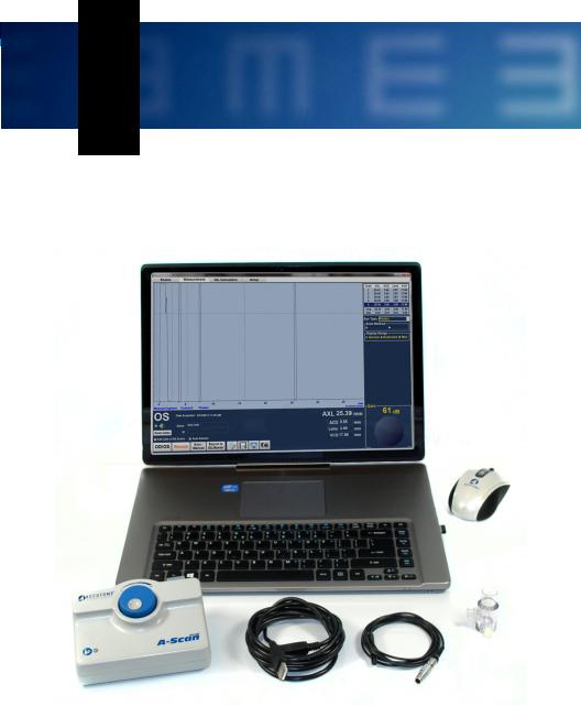
Accutome A-Scan Plus Connect Overview
The Accutome A-Scan Plus Connect pictured below has all the features that make it easy to obtain scans with extreme accuracy and improved patient outcomes.
Figure 1.1 - Accutome A-Scan Plus Connect
(800) 979.2020 US & CA • (610) 889.0200 International • +31 (0) 485.350300 Europe • www.accutome.com |
|
1 |
|

Accutome A-Scan Plus Connect Manual
Features
The Accutome A-scan Plus Connect is designed for easy access to all screens and functions.
The windows based software and proprietary universal interface provides unsurpassed ease of use and the straightforward Graphical User Interface guides you through every operation.
What you can’t see on the surface is also important. Industry-leading signal acquisition and processing helps you assure accurate measurements. Reliable design and efficient manufacturing provide fiscal value. Upgradable software protects your investment.
The A-Scan provides the following general features:
•Use on any Windows based computer
•Universal interface and probe
•Easily updated software
•Provides a variety of printouts
•Portable
Measurements
The accuracy of the Accutome A-Scan Plus Connect measurement is provided by the following:
•High-resolution, real-time waveform display
•High-speed digitalization acquires over 4000 points per waveform
•Continuous display of Axial Length, ACD, Lens Thickness, and Vitreous dimensions
•Audible feedback of contact and capture
•Immersion mode yields improved accuracy - Contact mode also supported
•Automatically or Manually capture up to 5 waveforms for each eye
•Adjustable Gain, Velocities, Gates, and Amplitude Thresholds
•Modify all waveform parameters using real-time or frozen waveforms
•Predefined Eye Types and Velocities handle most situations such as phakic, dense cataract, three types of pseudo-phakic, aphakic, silicone oil filled, and even phakic ICL eyes. All velocities are fully adjustable
•Custom Eye Types and Material Velocities can be created to handle individual preferences, special pathologies, or future trends
•Highly sensitive 10MHz composite Broadband probe features a fixation light and multiple mounting options
IOL Calculations
The Accutome A-Scan Plus Connect is also a leader in IOL Calculations and provides the following:
•Modern formulas including Hoffer Q, Holladay, SRK/T, and Haigis
•Compare results of all formulas simultaneously on a single screen for selected lenses
•Instantly calculates emmetropic and targeted ametropoic IOL powers for dozens of lenses, viewed four at a time, using the average of selected waveforms, a single waveform, or manually entered data
•Conveniently group lenses by favorite designation such as surgeon, user,
2 www.accutome.com • (800) 979.2020 US & CA • (610) 889.0200 International • +31 (0) 485.350300 Europe

Introduction
type, manufacturer, etc.
•Personalization of IOL Constants is easy and straightforward, encouraging improved patient outcomes
•Maintains individual IOL Constants for each formula. Clearly identifies which IOL constant is used with the selected formula
•IOL Calculation for Post Refractive Surgery Patients
Components
The components that are standard with each Accutome A-Scan Plus Connect instrument are:
•Ultrasonic probe
•Control Unit
•Footswitch
•Software CD which contains:
•User’s Guide
•System Software (to be loaded onto PC)
•A-B Type USB Cable
•Test Block
•Installation Instructions
•Quick Reference Guide
Optional Components
There is an additional component which further simplifies the use of the Accutome A-Scan Plus Connect:
• Immersion Shell
About this Manual
Chapter 2 - Safety
Summarizes safety precautions, warnings, symbols, and terms.
Chapter 3 - Getting Started
Provides assembly instructions, overview of Accutome A-Scan Plus Connect basic operation.
Chapter 4 - How To Navigate Screens and Buttons
Describes the interface and how to use all the buttons and screens.
Chapter 5 - Setting Up Personal Preferences
Provides instructions on how to set up custom eye types and system personal preferences.
Chapter 6 - Entering Patient Information
Provides instructions on how to create a new exam and enter patient’s information.
Chapter 7 - Measuring Patient
Describes how to measure an eye.
(800) 979.2020 US & CA • (610) 889.0200 International • +31 (0) 485.350300 Europe • www.accutome.com |
|
3 |
|

Accutome A-Scan Plus Connect Manual
Chapter 8 - Performing Calculations
Describes the steps necessary to calculate IOL Power.
Chapter 9 - Synergy Mode
Provides instructions on how to set up and use the Synergy Software
Chapter 10 - Maintenance
Provides general maintenance instructions.
Chapter 11 - Specifications
Provides Accutome A-Scan Plus Connect physical and operational specifications.
Chapter 12 - Warranty and Repair
Describes Accutome A-Scan Plus Connect warranty information and repair procedures.
4 www.accutome.com • (800) 979.2020 US & CA • (610) 889.0200 International • +31 (0) 485.350300 Europe

2Safety
Safety Information
The section lists:
•Safety Precautions associated with the Accutome A-Scan Plus Connect
•Safety Precautions of a general nature
Federal law restricts this device to sale by or on the order of a physician.
Safety Issues to Consider When Using the Accutome A-Scan Plus Connect
This instrument has no user operated controls or settings that affect the acoustic output. The Accutome A-Scan Plus Connect is noninvasive. The ultrasonic biometry probe touches the surface of the anesthetized cornea during the scanning process. Energy in the form of ultrasound is transmitted into the eye. The maximum power allowed to be set by the application software and or by the user is below the FDA, HEALTH CANADA and EU maximum power limits.
Indications for use
This instrument is used for measuring the axial length, anterior chamber depth and lens thickness of the eye. It also is used for calculating the optical power of the IOL to be implanted during cataract surgery.
Side Effects
There are no known side effects associated with the use of A-scan ultra sound imaging.
Any side effects associated with the use of the Accutome A-scan Plus Connect are related to the topical anesthetic chosen by the physician, used to anesthetize the eye of the patient.
Please consult the warning label of the chosen topical anesthetic for further information.
Contraindications
There are no known contraindications associated with the use of the A-scan Plus Connect.
(800) 979.2020 US & CA • (610) 889.0200 International • +31 (0) 485.350300 Europe • www.accutome.com |
|
5 |
|
Accutome A-Scan Plus Connect Manual
Symbol Definitions for the Accutome A-Scan Plus Connect
Statements, graphics and symbols listed below are used on components of the Accutome A-Scan Plus Connect. Descriptions and meanings are listed to the right of the symbols.
Disinfection and Cleaning
Disinfection issues are confined to the Accutome probe that comes in contact with the patient’s eye. In order to prevent the transmission of disease, refer to the OSHA and CDC guidelines for proper control of disinfection. These guidelines are frequently updated so be sure to contact OSHA, CDC, or your local disease control for the latest information and disinfection technique.
Accessories such as the extension handle or Goldman Tonometer Adapter which might come in contact with eye fluids should be cleaned with an FDA cleared high level disinfectant.
The probe must be cleaned between patients to prevent patient-to- patient transfer of infection. It is the user’s responsibility to ensure that the relevant standards are maintained and that the products and procedures are effective
and appropriate for ophthalmic applications. The following information is provided for the guidance of users, and specific
products are mentioned for illustration only of these or any other product. Products manufacturer’s instructions.
Symbol Definitions for the A-Scan Plus Connect
Attention! Consult
Instruction Manual
Type BF Medical
Device
No User
Serviceable Parts
Do Not Use
Near Flammable
Gasses
USB Connector
Disposal of Product within the EU
Safety Precautions
There are several areas in the use of the above Accutome products that require special attention, as they may pose a safety threat.
DO NOT AUTOCLAVE THE PROBES OR CONNECTORS.
DO NOT IMMERSE THE PROBE’S CABLES OR METAL CONNECTORS. ALLOW TO DRY BEFORE USE.
6 www.accutome.com • (800) 979.2020 US & CA • (610) 889.0200 International • +31 (0) 485.350300 Europe

Safety
DO NOT IMMERSE THE PROBE TIPS IN TAP WATER. USE DISTILLED WATER FOR CLEANING AND DISINFECTION
Cleaning Procedure at Point of Use
1.Wear protective gloves when performing the cleaning process.
2.Disconnect the probe from the system.
3.Use a soft cloth lightly dampened in a mild soap or compatible cleaning solution to remove any particulate matter or body fluids that remain on the probe or cable.
4.To remove remaining particulates, rinse with a distilled water-dampened cloth to remove soap residue, and then wipe with a dry cloth.
Disinfection of the Probes with Alcohol
One recommended disinfection technique is to clean the probe assemblies with 70% isopropyl alcohol.
A 5-10 minute exposure is recommended. It is imperative that the alcohol be given to time to evaporate before applying a probe to that patient’s eye. Do not completely immerse the probe or cable, only the tip of the probe should be placed in the solution.
After cleaning, rinse the end of the probe thoroughly with distilled water to remove all traces of the liquid used. Probe surfaces should be dried with a lint-free cloth.
HighLevel Disinfection of the Probe
If high level disinfection is required by your facility, the probe may be cleaned using an FDA cleared high level disinfectant, such as Cidex® OPA Activated Dialdehyde Solution. If your facility is located in the EU, Mikrozid wipes are a compatible method of high-level disinfection for Accutome probes.
Note: Be sure to follow the disinfectant manufacturer’s written protocol when using any antibacterial solution, including high level disinfectants.
WARNING!! DO NOT AUTOCLAVE the probe, probe cable, or any other parts of the A-Scan Plus Connect product.
WARNING!! DO NOT IMMERSE THE PROBE’S CABLE OR METAL CONNECTOR. ALLOW probe TO DRY BEFORE USE.
CAUTION: General indications for use of the Accutome probe include external, structurally intact areas of the eye globe and orbit areas only.
Electrical Hazard and Safety
The instrument, footswitch and probe of the Accutome A-Scan Plus Connect are electrical/electronic devices. The A-Scan Plus Connect control unit is a USB powered device. Reasonable care should be taken when making electrical connection and handling electrically powered devices. Avoid use of damaged electrical equipment or frayed electrical cords. If repair or maintenance is being
performed on the Accutome A-scan Plus Connect, the equipment must be turned off and the power cord disconnected.
(800) 979.2020 US & CA • (610) 889.0200 International • +31 (0) 485.350300 Europe • www.accutome.com |
|
7 |
|

Accutome A-Scan Plus Connect Manual
Covers must not be removed except by qualified personnel. To avoid injury, do not operate the Accutome A-scan Plus Connect without protective covers.
Use only Accutome provided probe, footswitch and USB cable (connection between Control Unit and laptop PC). Also, be sure the cable and connectors are in good condition. Inspect the probe before each use to ensure that there are no breaks, cracks, or other damage.
WARNING! THE A-Scan Plus Connect IS ONLY TO BE USED WITH A COMPUTER USING MEDICAL GRADE POWER SUPPLY COMPLIANT with IEC60601-1
Please refer to the manufacturer’s instructions regarding its use. The User is responsible for ensuring that the PC to which the
A-Scan Plus Connect system is connected must be of the grounding type in compliance with applicable electrical codes.
To avoid interruption of a procedure, the user is responsible for ensuring that all power and USB connections are secure and that the laptop is fully charged.
CAUTION: To avoid possible loss of patient data stored in the PC, ensure that the data is backed up on some device external to the PC.
CAUTION: The A connector type, Version 1.1 USB ports on the Control Unit should be used only for low power devices such as the footswitch, a memory “stick”, or a mouse.
Avoiding Equipment Damage
The Accutome A-Scan Plus Connect provides no explosion protection from static discharge or arcing components. Do not operate the instrument in the presence of explosive gases such as flammable mixtures of anesthetic and air, or nitrous oxide. CAUTION: This Device is intended for use in a controlled environment only; it is not intended for outdoor use.
Warning: Operating or storing the device beyond the environmental ranges in the Specifications Chapter may result in erroneous readings and/or premature failure of the device.
Avoiding Electromagnetic and Other Interference
Do not use a cellular telephone and other devices not complying with EMC Class B requirements, as its signals may cause the equipment to malfunction. The effect of radio signals on medical devices is dependent on various factors and therefore unpredictable.
To avoid electromagnetic interference, the device must be installed and put into operation in accordance with the user manual and using the components supplied by Accutome.
Warning!! the use of accessories, transducers and cables other than those specified by the manufacturer may result in increased emissions or decreased immunity of the a-scan plus connect.
Warning!! the a-scan plus connect should not be used adjacent to or stacked with other equipment and that if adjacent or stacked use is necessary, the a-scan plus connect should be observed to verify normal operation in the configuration in which it will be used.
8 www.accutome.com • (800) 979.2020 US & CA • (610) 889.0200 International • +31 (0) 485.350300 Europe

3 Getting Started
Assembling the Accutome A-Scan Plus Connect
The Accutome A-Scan Plus Connect measures the axial length of the eye and calculates the power of the intraocular lens.
The product consists of an A-Scan Plus Connect Control Unit, 10 MHz composite a-probe, a USB foot switch, USB Cable (A-B type), test block, quick reference/ installation guide and a CD containing the Accutome A-Scan Plus Connect software, all in a plastic carrying case.
The user supplies a windows based personal computer with Microsoft XP service pack 2 or higher.
The Accutome A-Scan Plus Connect is designed to be used in multiple environments and is as simple as carrying a notebook computer and probe. The instrument requires virtually no assembly. You simply install the software and plug the USB Control Unit with probe into your computers USB port. The USB foot switch can either be plugged in the A-Scan Plus Connect Control Unit or any unused USB port in the computer.
What you Need
For a complete Accutome A-Scan Plus Connect environment you will need the following:
•Windows based Personal Computer
•Windows based XP SP2 or newer
•Intel Core 2 Duo (2.40GHz or higher)
•4M L2 Cache, 66MHz
•4 USB ports version 2.0
•Accutome A-Scan Plus Connect Control Unit
•Accutome A-Scan Plus Connect 10MHz composite probe
•USB Footswitch
•Accutome A-Scan Plus Connect software
•A-B type USB cable (Control Unit to laptop computer)
•Printer (to print out reports)
Note: It is recommended that the PC be compliant with IEC 60601-1 and IEC 60601-1-2.
(800) 979.2020 US & CA • (610) 889.0200 International • +31 (0) 485.350300 Europe • www.accutome.com |
|
9 |
|
Accutome A-Scan Plus Connect Manual
Personal Computer Specifications
Table 3.1 - Personal Computer Specifications
PC |
Windows based PC, with Intel Duo (2.40 GHz) 4M L2 Cache, |
|
667 MHz Dual Core or higher |
||
|
||
|
|
|
I/O Ports |
Minimum 3 USB 2.0 |
|
|
|
|
Operating Systems |
Windows® XP Professional, SP2 or newer |
|
|
|
|
Display |
15.4 inch WSXGA + LCD or larger |
|
|
|
|
Memory |
2.0 GB, DDR2-667 SDRAM |
|
|
|
|
Hard Disk Drive |
80 GB, Hard Disk Drive, 9.5 MM, 7200 RPM |
|
|
|
|
CD/DVD Drive |
8X DVD+/-RW w/Roxio Software™ and Cyberlink Power DVD |
|
|
|
|
Video Controller |
256 MB NVIDIA® Quadro NVS 100M TurboCache™ |
|
|
|
A-Scan Plus Connect Control Unit
The A-Scan Plus Connect Control Unit connects the A-probe to the computer. The Control Unit contains all the ports that connect the Control Unit to the computer, the analog to digital amplifier electronics, external gain control, A-probe connection and three (versions 1.1) USB ports, which may be used for foot switch and mouse.
CAUTION: The A connector type, Version 1.1 USB ports on the Control Unit should be used only for low power devices such as the footswitch, a memory “stick”, or a mouse.
A-Scan Plus Connect 10MHz Composite A-Probe
The A-probe included with A-Scan Plus Connect is an essential component. No other probes should be used with the system unless authorized by Accutome Inc.
USB Foot Switch
The foot switch is used to stop, start and review the axial length measurements.
A-B Type USB Cable (Control Unit to Computer)
A USB cable is provided to connect the A-Scan Plus Connect Control Unit to the computer.
Printer
In order to print out the measurements and the IOL calculations, you will need a local or network printer attached to the PC.
Accutome A-Scan Plus Connect Software
The software for the Accutome A-Scan Plus Connect is provided on a CD or can be found on Accutome’s Support site at support.accutome.com.
10 www.accutome.com • (800) 979.2020 US & CA • (610) 889.0200 International • +31 (0) 485.350300 Europe
Getting Started
Assembling the A-Scan Plus Connect
CAUTION: Do not connect the A-Scan Plus Connect to the computer until the software has been loaded and instructed to do so.
Assemble the personal computer according to the manufacturer’s instructions. Connect the printer according to the manufacturer’s instructions.
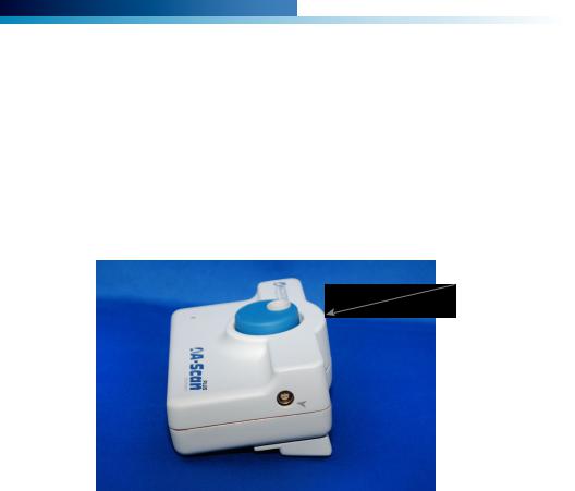
Connecting the Probe
The Accutome A-Scan Plus Connect probe connector is located on the right side of the instrument (facing the instrument).
To connect the probe:
1.Locate the probe connector, which is located on the right side of the control unit (see Figure 3.1 below.)
Control Unit
 Probe Connector
Figure 3.1 - Control Unit and Probe Connector (Right Side of Instrument)
2.The probe connector is keyed and has a red dot indicating the key.
3.Insert the probe with the red dot facing the back of the instrument. (Refer to Figure 3.2 on next page.)
(800) 979.2020 US & CA • (610) 889.0200 International • +31 (0) 485.350300 Europe • www.accutome.com |
|
11 |
|
Accutome A-Scan Plus Connect Manual
Probe Setup
The Accutome A-Scan Plus Connect probe is an integral component. There are several options available for probe use. The Accutome A-Scan Plus Connect probe can be used:
1.With an immersion shell
2.Mounted into a Goldman Tonometer
3.With a probe handle extension
4.Freehand
Note: You cannot operate the Accutome A-Scan Plus Connect without the Accutome probe.
Probe
Figure 3.2 - Probe Connected
Probe Connector
Extension Handle Insertion Tool
Extension Handle
Goldman Tonometer
Adapter
Accutome Probe
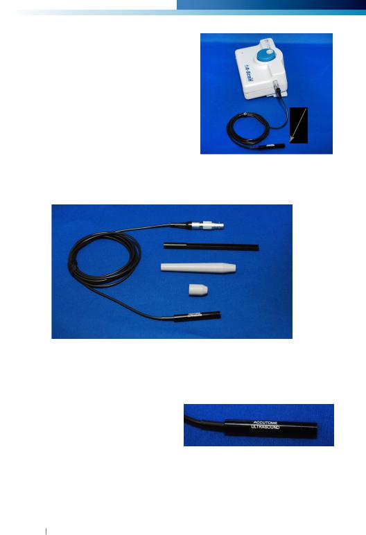
Figure 3.3 - Accutome Ultrasonic Probe Kit (PN 24-4001)
Accutome Ultrasonic Probe Kit (PN 24-4001)
The Accutome probe is designed to be |
|
used with an Immersion Shell. When |
|
using an immersion shell ensure that |
|
there is minimum a distance of 5mm |
|
between the bottom of the probe and |
|
the bottom of the immersion shell, as |
|
shown in Figure 3.5 on next page. |
Figure 3.4 - Accutome Probe |
|
12 www.accutome.com • (800) 979.2020 US & CA • (610) 889.0200 International • +31 (0) 485.350300 Europe

Getting Started
Accutome Probe with Goldman Tonometer Adapter
The Accutome probe is designed to be used with a Goldman Tonometer Adapter. When using the Tonometer Adapter:
1.Slide the adapter over the end of the probe as shown in Figure 3.6 below.
2.Mount the probe by inserting the adapter into the Goldman Tonometer.
Immersion Shell
Probe does not go further then  this line
Shell Bottom
Goldman Tonometer |
Figure 3.5 - Probe Setup |
|||
with Immersion Shell |
||||
Adapter |
|
|
||
|
|
|
||
Probe |
|
|
|
|
|
|
|||
Figure 3.6 - Probe with Goldman Tonometer Adapter
Accutome Probe with Handle Extension
The Accutome probe is designed to be used with a handle extension to increase the length of the probe. When using the probe handle extension:
1.Insert the probe into the handle extension as shown in Figure 3.7 below.
2.Slide the insertion tool into the handle extension making sure that the probe cable runs through the notched channel of the insertion tool.
3.Push the probe through the handle extension until the tip of the probe emerges from the extension.
4.Remove the insertion tool by sliding it back away from the handle extension.
Extension
Handle
Insertion Tool |
|
|
Probe |
|
|
Probe Cable |
Removing |
|
Insertion Tool |
||
|
Probe inside Handle Extension
Figure 3.7 - Inserting the Probe into the Handle Extension
(800) 979.2020 US & CA • (610) 889.0200 International • +31 (0) 485.350300 Europe • www.accutome.com |
|
13 |
|

Accutome A-Scan Plus Connect Manual
Figure 3.8 - Probe with Handle Extension and Insertion Tool
Figure 3.9 - Probe with Handle Extension
Figure 3.10 - A-Scan Plus Connect Control Unit Connect to a Laptop via USB Cable
Connecting the A-Scan Plus Connect to the Computer
Connect the foot switch to either an unused USB port located with in the computer or the A-Scan Plus Connect Control Unit.
Connect the receiver of the mouse to an unused USB port located within the A-Scan Plus Connect Control Unit.
Installation of the Software
Please see the A-Scan Plus Connect Installation Instructions for all Windows
14 www.accutome.com • (800) 979.2020 US & CA • (610) 889.0200 International • +31 (0) 485.350300 Europe

Getting Started
operating systems, which are included in the carrying case.
Connect the A-Scan Plus Connect Control Unit to the computer via USB cable.
A red indicator on the A-Scan Plus Connect Control Unit indicates that the Control Unit is powered up by the PC but Windows operation system (OS) is not seeing the Control Unit. If the Windows device driver was installed correctly, it will change to either yellow or green.
A green indicator on the A-Scan Plus Connect Control Unit indicates that the Accutome A-Scan Plus Connect is installed correctly and ready to measure patients.
A yellow indicator on the A-Scan Plus Connect Control Unit indicates that the A-Scan probe is not connected to the A-scan Plus Connect.
During normal operation, every time the Control Unit is powered up the indicator will turn red at first, then turn to green or yellow. A continuous red (more than 3 seconds) means the device driver is not installed correctly.
Note: Please see table A-1 in the appendix for resolving the problem of a red and yellow indicator.
The Control Unit will be powered on immediately after being plugged into a PC and stay on until it is unplugged. To turn it off, just unplug the USB cable from the PC. The A-Scan Plus Connect software application is fully functioning even without the Control Unit. The only limitation is not being able to take new scans.
Basic Operation
The basic operation of the Accutome A-Scan Plus Connect consists of the following steps:
1.Turn on computer.
2.Connect the control unit.
3.Start the Accutome program. Refer to “Starting the A-Scan Plus Connect Program.”
4.Start a “New Exam.” Refer to “How to Start a New Exam.”
5.Enter patient information. Refer to “How to Enter Patient Information.”
6.Take five measurements per eye.
7.Calculate the IOL power for desired results.
8.Print or save the Patient Record
Starting Accutome A-Scan Plus Connect Program
The Accutome A-Scan Plus Connect program is launched like any other Windows program, either through a shortcut on the desktop or by accessing the “Start” programs menu.
If launching the A-Scan Plus Connect software from the desktop, click on the icon displayed below. The A-Scan Plus Connect software will display at the Exams screen, figure 3.11.
Figure 3.10 - Accutome A-Scan Plus Connect Desktop Shortcut
(800) 979.2020 US & CA • (610) 889.0200 International • +31 (0) 485.350300 Europe • www.accutome.com |
|
15 |
|
Accutome A-Scan Plus Connect Manual
How to Start a New Patient Exam
To start a new Patient exam:
1.On the Accutome Exam Screen, click on “New.” Refer to Figure 3.11 below.
Figure 3.11 - Main Screen Starting New Exam
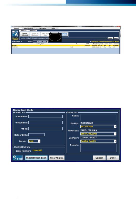
Entering Patient Exam Information
After you execute “New” from the Accutome A-Scan Plus Connect Exams screen, the New A-Scan Study screen will launch as shown in Figure 3.12. The pre-filled information fields are from the setup defaults.
1.When you start a new exam the Accutome A-Scan Plus Connect will launch the New A-scan Study Screen shown in Figure 3.12 and will clear all patient info fields.
Note: The Patient/Exam Info Screen contains drop down lists that are created during A-Scan Plus Connect setup. Refer to the Setup chapter for further information.
Figure 3.12 - New A-scan Study Screen
2. Enter information in data fields by left clicking in each field and typing accordingly. In Figure 3-13 below the Last Name field has just been completed.
To move from one field to another you may use the Tab Key on your computer keyboard or simply click on the field.
16 www.accutome.com • (800) 979.2020 US & CA • (610) 889.0200 International • +31 (0) 485.350300 Europe

Getting Started
Figure 3.13 - Entering New Patient Information
3.The Patient Info must be entered to proceed to the next screen. Select the First Name field and enter the Patient First Name.
4.Use the Tab key, or select the Last Name field and enter the Patient Last Name.
5.Continue entering all relevant patient information.
6.If you wish to select a Facility, select one from the predefined (in A-Scan Plus Connect Setup) facility drop down list. Position the cursor on the small arrow at the right of the facility field. Left click to open the drop down list. Position the mouse over the up/down arrows at the right of the drop down list Click the mouse to move through stored facilities. Once you see the facility you want to select, position the mouse cursor over the facility and left click. The selected facility will fill in the facility field.
Figure 3.14 - Selection Facility
(800) 979.2020 US & CA • (610) 889.0200 International • +31 (0) 485.350300 Europe • www.accutome.com |
|
17 |
|

Accutome A-Scan Plus Connect Manual
7.Continue to select Physician and Operator from the drop down lists located at the right side of the each field. Position the cursor on the small arrow at the right of the physician and operators fields. Left click to open the drop down list. Position the mouse over the up/down arrows at the right of the drop down list. Click the mouse to move through stored physicians and operators. Once you see the Physician and Operators you want to select, position the mouse cursor over the Physician and Operator and left click. The selected Physician and Operator will fill in the Physician and Operator field.
Figure 3.15 - Selection Physician.
Figure 3.16 - Selecting Operator
18 www.accutome.com • (800) 979.2020 US & CA • (610) 889.0200 International • +31 (0) 485.350300 Europe
Getting Started
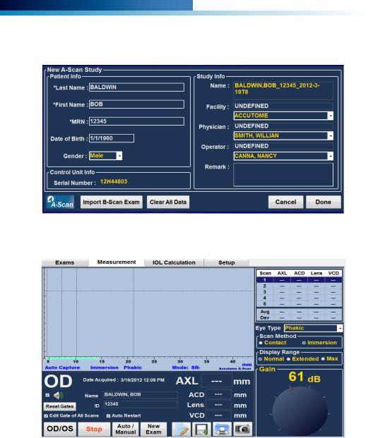
8.Click on the “Done” button, located at the bottom right of the New A-scan Study Screen.
Figure 3.17 - Click Done Creating a New Exam
9. The A-Scan Plus Connect will launch the Exam Screen shown below.
Figure 3.18 - Measurement Screen
Using the Test Block
The Accutome A-Scan Plus Connect comes with a test block included as an accessory. Refer to the figure below. The test block is provided as a convenient way to test the functionality of the instrument and probe.
(800) 979.2020 US & CA • (610) 889.0200 International • +31 (0) 485.350300 Europe • www.accutome.com |
|
19 |
|
 Loading...