

Page 1

EVOLUTION GAS STEAMER
EVOLUTION G asSteame rStart -Up Form
AccuTemp Products, Inc.
Location : ___________________A ddr ess: ________________________________
City:_________________ State: _______ Zip: _________ Ph#________________
SerialNumber _________ ModelNumber:_________________________________
ServiceAgency: ______________________ Technician:_____________________
NOTE:
AccuTempProducts, Inc. is not responsible for theinstallation and/or modifications to the electrical orgas supply
sources.
It is recommended that the wall receptacle be placed aslow as State and Local codes allow.Placement in high heat
zonessuch as, just above, below orbeside the exhaust flue, will causeservice issues that will not becovered under
theproduct warranty.
Ane xternal regulator sh ouldnot be used unless the supplygas pressure is more than 0.5 psig.)
If the altitude is greater tha n2, 000 feet above sea level, conta ct the AccuTemp Technica lS ervices Department to
verifythe correct orificesize for main burner.
1. Isthe steamer beinginstalled at analtitude greater than 2,000 feet?(circle one) Yes/ No
2. Is an external regulator connectedto the steamer? (circle one)Yes /No
3. Isthe 120 Vac or240 Vac wall receptacleposition in alow heat zone. (circleone) Yes / No
4. If the steamer has legs, havethe (4) rubber foot tips been installed?(circle one) Yes /No
5. Is the steamer level ?( circleone) Yes /No
6. Is thesteamer hard connectedto the gassupply line? (circleone) Yes / No
7. If the steameris connected witha flexible hose,is a restraining device used? (circle one) Yes / No
8. Gas Pressure Measurements: Natural : _____ 5” WC (Regulator Valve PressureTap – 1/8” NPT)
Propane: _____ 10” WC (Regulator Valve Pressure Tap –1/8” NPT)
9. Does the steamer operate properly when all gas appliances are operating? (circle one) Yes/ No
10. Verifythe water temperature in COOK MODE ( _______°F)
Iaccept this Start-UpForm as complete and accurate:
___________________________________Restaurant Management Date:___/___/___
Note: This Start-UpFormmust becompletelyfilledout and faxedor mailed to theAccuTempTechnical&
CustomerSupport Department, before thewarranty is activated.
AccuTempProducts, Inc
Attn: Technical& Customer SupportDepartment
8415North ClintonPark
Ft.Wayne, IN 46825
Phone:+1-260-469-0415 or 1-800-480-0415
Fax: +1-260-493-8914
INSTALLATION & OWNERS MANUAL
SERIAL #
MODEL #
Please ll in your Serial # and Model # for quick reference when calling
AccuTemp Technical Service for support.
IMPORTANT WARRANTY INFORMATION
WARRANTY REGISTRATION - STARTUP FORM INSIDE THIS MANUAL MUST BE
REMOVED, COMPLETED, SIGNED BY CUSTOMER AND A COPY EMAILED, FAXED OR
MAILED BACK TO ACTIVATE THE WARRANTY PERIOD.
MP4010-1003
These installation instructions have been prepared for qualied gas and
electric equipment installation personnel, who should perform the installation,
initial eld start-up and complete the equipment adjustments described in this
manual.
REGISTRATION AND STARTUP FORM
EVOLUTION GAS STEAMER
Page 2

This Page Left Intentionally Blank
MP4010-1003
EVOLUTION GAS STEAMER
Page 3

IMPORTANT FOR YOUR SAFETY
The safety instructions listed below on this page should be posted in a
prominent location as a reminder of safe practices as well as recommended
actions to follow in the event of an equipment or facility utility issue.
WARNING
In the event a gas odor is detected, shut down all appliances at the main
gas shut-off valve and contact the local gas company or gas supplier service.
WARNING
WARNING
In the event of a power failure, do not attempt to operate this appliance.
WARNING
Do not store or use gasoline or other ammable vapors or liquids in the vicinity of this or
any other appliance.
WARNING
Improper installation, adjustment, alteration, service or maintenance can cause property
damage, injury or death. Read the installation, operating, and maintenance instructions
thoroughly before installing or servicing this equipment.
WARNING
Only qualied service technicians/electricians should perform the installation to ensure
that all electrical and safety requirements are met and that all wiring is performed in
accordance with all national, state and local electrical codes.
MP4010-1003
EVOLUTION GAS STEAMER
Page 4

This Page Left Intentionally Blank
MP4010-1003
EVOLUTION GAS STEAMER
Page 5

EVOLUTION Gas Steamer Start-Up Form
AccuTemp Products, Inc.
Location: ___________________ Address: ________________________________
City: _________________ State: _______ Zip: _________ Ph#________________
Serial Number _________ Model Number: _________________________________
Service Agency: ______________________ Technician: _____________________
NOTE:
AccuTemp Products, Inc. is not responsible for the installation and/or modications to the •
electrical or gas supply sources.
It is recommended that the wall receptacle be placed as low as State and Local codes allow. •
Placement in high heat zones such as, just above, below or beside the exhaust ue, will cause
service issues that will not be covered under the product warranty.
An external regulator should not be used unless the supply gas pressure is more than 0.5 psig.)•
If the altitude is greater than 2,000 feet above sea level, contact the AccuTemp Technical Services •
Department to verify the correct orice size for main burner.
Is the steamer being installed at an altitude greater than 2,000 feet? (circle one) Yes / No1.
Is an external regulator connected to the steamer? (circle one) Yes / No2.
Is the 120 Vac or 240 Vac wall receptacle position in a low heat zone. (circle one) Yes / No3.
If the steamer has legs, have the (4) rubber foot tips been installed ? (circle one) Yes / No4.
Is the steamer level ? (circle one) Yes / No5.
Is the steamer hard connected to the gas supply line? (circle one) Yes / No6.
If the steamer is connected with a exible hose, is a restraining device used? (circle one) Yes / No7.
Gas Pressure Measurements: Natural : _____ 5” WC (Regulator Valve Pressure Tap – 1/8” NPT) 8.
Propane : _____ 10” WC (Regulator Valve Pressure Tap – 1/8” NPT)
Does the steamer operate properly when all gas appliances are operating? (circle one) Yes / No9.
Verify the water temperature in COOK MODE ( _______°F)10.
I accept this Start-Up Form as complete and accurate:
___________________________________ Restaurant Management Date: ___/___/___
Note: This Start-Up Form must be completely lled out, emailed, faxed or mailed to the AccuTemp
Technical & Customer Support Department, before the warranty is activated.
AccuTemp Products, Inc
Attn: Technical & Customer Support Department
8415 North Clinton Park
Ft. Wayne, IN 46825
Phone: 260.469.0415 or 800.480.0415
Fax: 260.493.8914
email: service@accutemp.net
MP4010-1003
EVOLUTION GAS STEAMER
Page 6

This Page Left Intentionally Blank
MP4010-1003
EVOLUTION GAS STEAMER
Page 7

TABLE OF CONTENTS
TABLE OF CONTENTS PAGE 1
DOCUMENT HISTORY PAGE 1
SAFETY WARNINGS INFORMATION PAGES 2-3
INSTALLATION PAGES 4-12
OPERATION - ALL MODELS PAGES 13-16
OPERATION - CONNECTED PAGES 17-18
OPERATION CONNECTIONLESS PAGES 19-20
TROUBLESHOOTING PAGES 21-22
SERVICE PAGE 23
WARRANTY PAGE 24
DOCUMENT HISTORY
CURRENT
REVISION
1003 4/14/10 N/A N/A Initial release of manual
MP4010-1003
DATE PRIOR
REVISION
DATE CHANGE
EVOLUTION GAS STEAMER
1
Page 8

SAFETY WARNINGS
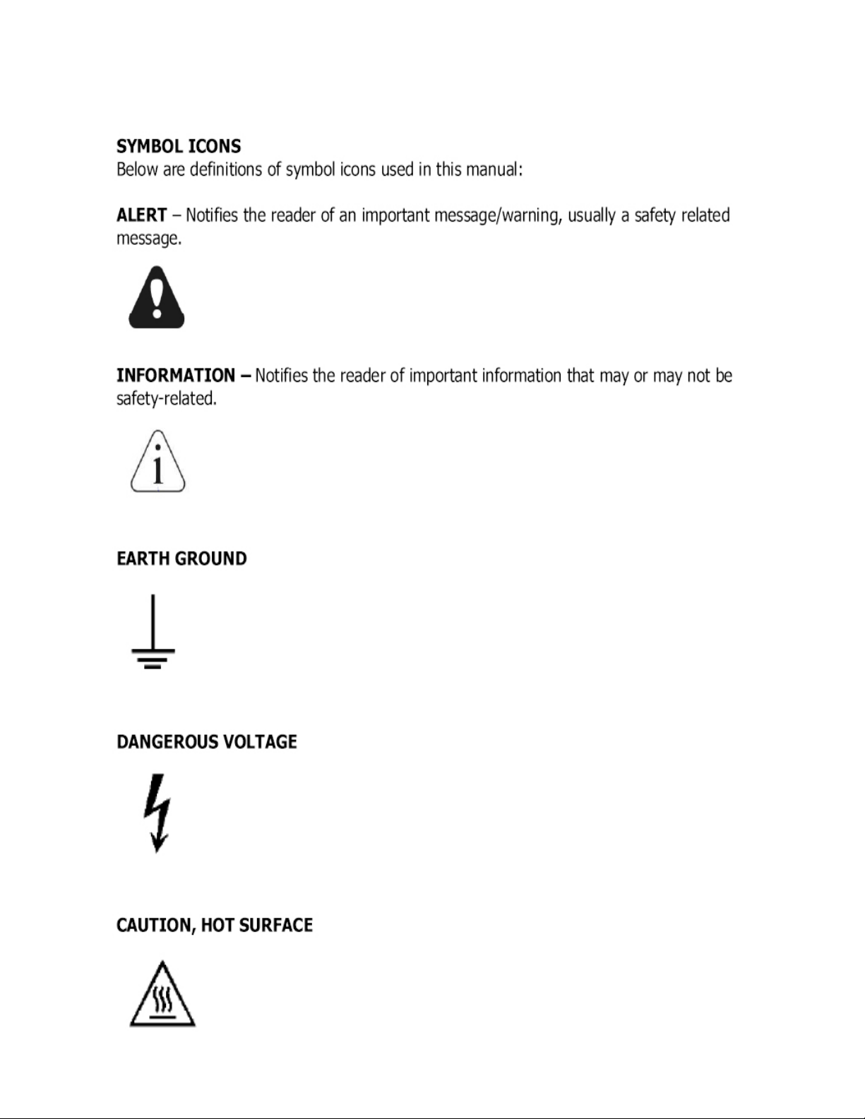
SYMBOL DEFINITIONS
Symbols are used to attract your attention to possible dangers. They are only effective if the operator
uses proper accident prevention measures. Some of the symbols are boxed text, while other maybe
just picture icons. Please give this information the respect they deserve for safe operation.
WARNING TEXT BOXES
Below are denitions of the warning text boxes:
DANGER
Indicates a imminently hazardous situation which, if not avoided will, result in death or
serious injury
WARNING•
Indicates a potentially hazardous situation which, if not avoided, will result in death or
serious injury
CAUTION
Indicates a potentially hazardous situation which, if not avoided will result in minor or
moderate injury
NOTE
Advises reader of information or instructions vital to the operation or maintenance of the
equipment
MP4010-1003
EVOLUTION GAS STEAMER
2
Page 9
SAFETY WARNINGS
MP4010-1003
EVOLUTION GAS STEAMER
3
Page 10

INSTALLATION
Only qualied service technicians/electricians should preform the installation to ensure that all
electrical, gas and safety requirements are met and that all wiring, gas and plumbing installations are
preformed in accordance with all national, state and local codes.
The installation must conform with local codes, or in the absence of local codes, with the National
Fuel Gas Code, ANSA/NFPA 54, or the Natural Gas and Propane Installation Code, CSA B149.1 as
applicable.
The appliance and its individual shutoff must be disconnected from the gas supply piping system
during any pressure testing of that system at test pressures in excess of 1/2 PSI(3.5kPA)
LOCATION AND PLACEMENT
The AccuTemp Evolution gas steamer can be placed on a commercial kitchen counter-top, ush
mounted or installed on a AccuTemp Evolution gas steamer stand. Provisions should be incorporated
in the kitchen to ensure an adequate supply of fresh air for proper combustion and ventilation. See
Fig. 1
EQUIPMENT CLEARANCE
LOCATION COMBUSTIBLE NONCOMBUSTIBLE
SIDES 1” 0”
REAR 2” 0”
Fig. 1
UNPACKING
This appliance was carefully inspected before shipment from the factory. The transportation
company assumes full responsibility for safe delivery to the customer until customer acceptance of
the package. Careful inspection of the packaging and the appliance should be completed before
acceptance from the transportation company.
STEAMER LIFTING
Steamers are heavy enough to require additional manpower or powered assistance when installing or
moving the steamer.
LEVELING
The steamer must be installed in a level condition. An out of level condition may cause erratic operation and damage to the steamer. Damage of this kind is not covered by the limited warranty. Use a
spirit level resting on the top surface of the steamer to ensure it is level front to back and left to right.
COUNTER TOP INSTALLATION
In a counter top installation the steamer is leveled using the adjusters on the legs of the steamer.
Once this is complete it is required that the supplied (4) rubber foot tips must be installed to keep the
steamer from possibly sliding on the counter top under normal use.
STAND INSTALLATION
If a AccuTemp Evolution Gas Steamer Stand is used ensure the oor is level and place the two locking casters to the “ON” position.
All AccuTemp Evolution Gas Steamer Stand with casters, shall be made with a connector that complies with the Standard for Connectors for Movable Gas Appliances, ANSI Z21.69 or CAN/CGA 6.16
and a quick disconnect device that complies with the Standard for Quick Disconnect Devices for Use
with Gas Fuel, ANSI Z21.41 or CAN1-6.9.
MP4010-1003
EVOLUTION GAS STEAMER
4
Page 11

INSTALLATION
WARNING
When using a stand that is equipped with casters, the oor surface must be level and
at. Failure to do so can result in a “tipping” hazard that could result in
serious injury.
STAND INSTALLATION
If a AccuTemp Evolution Gas Steamer Stand is used ensure the oor is level and place the two locking casters to the “ON” position.
All AccuTemp Evolution Gas Steamer Stand with casters, shall be made with a connector that complies with the Standard for Connectors for Movable Gas Appliances, ANSI Z21.69 or CAN/CGA 6.16
and a quick disconnect device that complies with the Standard for Quick Disconnect Devices for Use
with Gas Fuel, ANSI Z21.41 or CAN1-6.9.
SINGLE STEAMER STAND INSTALLATION
The AccuTemp single stand can be equipped with adjustable height feet or non-adjustable casters.
Before mounting a steamer on the stand with casters, engage the two front locking casters, pressing
on the “ON” handle of the brake mechanism. To mount the steamer, carefully lift and place it on the
horizontal mounting brackets ensuring that the (4) mounting holes on the underside of the Evolution
are lined up with mounting holes of the brackets. Then, using a 7/16” wrench, fasten one pair of the
1/4” -20 hex bolt and 1/4” split lock washer through the underside of each stand bracket mounting
hole into the Evolution and tighten securely. With the SNH10 stand, level the steamer by adjusting the
feet found at the ends of each stand leg, either up or down as needed.
DOUBLE STEAMER STAND INSTALLATION
The AccuTemp double stand can be equipped with adjustable height feet or can be equipped with
non-adjustable casters and accommodates (2) E6 model Evolutions. Before mounting a steamer
on a stand with casters engage the brakes on the two front locking casters, pressing on the “ON”
handle of the brake mechanism. Always mount the rst EVOLUTION on the bottom of the stand. To
mount the bottom steamer, carefully lift and place it on the horizontal mounting brackets, ensuring
that the (4) mounting holes on the underside of the Evolution are lined up with the mounting holes on
the brackets. Then, using a 7/16” wrench, fasten one pair of the 1/4"-20 hex bolts and 1/4" split lock
washers through the underside of each stand bracket mounting hole into the Evolution and tighten
securely. Once the bottom steamer has been installed, carefully lift and place the top Evolution
steamer on the horizontal mounting brackets, ensuring that the (4) mounting holes on the underside
of the Evolution are lined up with the mounting holes on the brackets. Then, using a 7/16” wrench,
fasten one pair of the 1/4"-20 hex bolts and 1/4" split lock washers through the underside of each
stand bracket mounting hole and tighten securely. With the SNH20 stand, level the appliances by
adjusting the feet found at the ends of each stand leg, either up or down as needed.
MP4010-1003
EVOLUTION GAS STEAMER
5
Page 12

INSTALLATION
FLUSH MOUNT
To Flush mount the appliance to a counter to:,
Drill 4 holes per above drawing. 1.
Attach the appliance to counter top with (4) 1/4-20 x 3/4” hex head bolts and 1/4-20 split lock 2.
washers.
Apply a bead of high temp food grade silicone caulking around the perimeter and smooth out.3.
Fig.2
STEAMER CONNECTIONS
The Evolution Gas Steamer is available in a connected and connection less models.
Both the connection-less and connected model will require a gas connection and a electrical
connection.
CONNECTED
The connected model in addition to the gas and electrical connection will require a water connection
and access to a oor drain or sink to route a drain hose (not supplied) to allow condensate to be
removed and to drain the steamer when required.
See Fig. for identications of the required steamer connections. See Fig. 3
CONNECTIONLESS
This model must be manually lled with tap water and must be lled throughout the cooking process
to assure consistent cook times. Do not use the “Low Water Indicator” as your indication that this
steamer requires water as this actually turns off the heat to the product thus stopping the cooking
process. A full size steam table pan or a 1/1 gastronome pan must installed in rails under the steamer
any time the steamer is operating and anytime that the steamer is being cleaned or drained of the
water in the cooking chamber. Failure to follow this directions will cause a the steamer to fail which is
not covered under the limited warranty. See Fig. 4
MP4010-1003
EVOLUTION GAS STEAMER
6
Page 13

INSTALLATION
CONNECTED EVOLUTION GAS STEAMER
STEAM EXHAUST VENT
DO NOT CONNECT TO GAS,
DRAIN OR WATER INLET
GAS EXHAUST FLUE
GAS CONNECTION
DRAIN CONNECTION
CONNECTED STEAMERS
ONLY
WATER CONNECTION
CONNECTED STEAMERS
ONLY - 60 PSI MAXIMUM
WATER PRESSURE
MP4010-1003
Fig. 3
EVOLUTION GAS STEAMER
7
Page 14

INSTALLATION
CONNECTIONLESS
OPERATOR KEYPAD
DATA TAG
Drain Pan - Customer
Supplied
DRAIN VALVE
MP4010-1003
Fig. 4
EVOLUTION GAS STEAMER
8
Page 15

INSTALLATION
ELECTRICAL REQUIREMENTS
The electrical voltage requirement is listed on the data plate that is located on the lower left side
panel. All AccuTemp Evolution Gas Steamers are supplied with a power cord and plug that must be
connected to a standard a 15A (120V) or 20A (240V) grounded receptacle. Make sure the voltage
is within 10% of the voltage listed on the steamer data plate. Connection to any other voltage not
identied on the data plate will cause damage to the components and is not covered under warranty.
GROUNDING INSTRUCTIONS
Grounding provides a path for electric current to reduce risk of shock. This product is equipped with
a power cord having a grounding plug. The plug must be plugged into a receptacle that is properly
installed and grounded in accordance with all National, State and local electrical codes or in the
absence of local electrical codes with the National Electric Code, ANSI/NFPA 70, or the Canadian
Code, CSA C22.2 as applicable. Under no circumstances shall the plugs grounding prong be cut or
bent to t a receptacle other than the one specied. Do not use any adapters.
WARNING
This appliance Must be properly grounded, in accordance with all National, State and
local electrical codes.
DANGER
Any in-eld modication made that bypass the safety features of this appliance will
result in serious injury or death.
WARNING
Any in-eld modications made without written authorization from AccuTemp
Products, Inc. will void all written and oral warranties.
MP4010-1003
EVOLUTION GAS STEAMER
9
Page 16

INSTALLATION
GAS CONNECTION - See Fig 5
The Evolution Gas Steamer is manufactured for the use of gas indicated on the data plate. Contact
AccuTemp Products Technical Service Department if your gas supply does not match the gas
indicated on the steamer data plate.
All gas connectors must be in accordance with the local codes and must comply with the latest edition
of the National Fuel Federal Gas Codes, ANSI Z223.1.
A separate gas shutoff valve (not supplied) should be installed in the gas supply line. Use a 1/2” or
larger diameter gas supply line to connect this steamer to the facility supply manifold to ensure a
sufcient volume of gas. The facility supply regulator and manifold must be sized according to the gas
load of all appliances connected to it. If other gas appliances are connected to the supply manifold,
their gas load must be added to the calculations for properly sizing the supply manifold and regulator.
Note: Flexible residential appliance connection hoses are not suitable for this appliance and will void
any warranty.
If your steamer is location is at an altitude of 2000 feet or higher, the orice must be changed to allow
appropriate gas supply to the burners. Please contact the AccuTemp Products Technical Services
Department for assistance.
The steamer is supplied with an internal gas regulator that is set for the gas type and pressures on
the steamer data plate. An external regulator is not required unless the gas supply pressure is more
than 0.5psig. If an external regulator is required it must be rated 125% of the steamer BTUH rate at
the pressure higher than the rated regulated pressure.
Fig. 5
GAS PRESSURE VERIFICATION
The gas supply pressures for the internal regulator must be veried with a calibrated manometer
while the appliance is operating in maximum load condition. A 1/8” NPT tap is provided in the
front of the internal regulator to measure the burner supply pressure. See Fig.6 Use a pipe joint
compound or sealant designed for the use with liqueed petroleum gas when replacing the 1/8”
NPT tap.
Do not use an excessive amount of sealant in order to prevent potential obstruction of the
gas control valve.
GAS PRESSURE ADJUSTMENT
GAS PRESSURE TAP
1. Remove dust cap
2. Turn adjustment screw to
Turn adjustment screw
clockwise to increase
pressure and counter
adjust pressure
Burner must be on before
clockwise to decrease
pressure.
adjusting
Fig. 6
MP4010-1003
EVOLUTION GAS STEAMER
10
Page 17

INSTALLATION
WATER LINE CONNECTION - CONNECTED MODELS
The Installer/Owner is responsible for the water connection of this appliance. This appliance is to be installed
to comply with all applicable federal, state, or local plumbing codes. The installation requires a check-valve
(or other approved anti-back ow / anti-siphon device) (not provided) in all supply lines in accordance with and
as required by local, state, and national health, sanitation, and plumbing codes.
Check local codes to determine exactly what type of anti-back ow / anti-siphon device is •
necessary to meet local requirements.
Design the water supply line so the unit can be moved for service. Install a manual water •
valve between the water supply line and the steamer supply line.
The Garden Hose Thread (GHT) connector used must be suitable for potable water•
Do not apply pipe thread sealant to GHT connections.•
Install a manual water shut-off valve (not provided)•
between the cold water supply line and the
appliance.
Either hot or cold water can be connected to the steamer. If hot is used, temperature •
must be less than 180°F.
A reinforced rubber or braided stainless steel appliance hose rated for the temperature and •
pressure of the water supply with a 3/4” garden hose type connection is required.
The hose must not be sharply bent, kinked or twisted.•
If the steamer is close to a wall, use a right angle tting to prevent kinking the hose•
Flush the water supply lines before connecting the lines to the appliance.•
Connect the water supply lines to the steamer.•
See Fig.7
QUICK DISCONNECT GAS CONNECTION - CUSTOMER
SUPPLIED
WATER LINE CONNECTION - CUSTOMER
SUPPLIED - 60 PSI MAXIMUM WATER PRESSURE
DRAIN HOSE - CUSTOMER SUPPLIED
Fig. 7
MP4010-1003
EVOLUTION GAS STEAMER
11
Page 18

VENTILATION
The steamer produces water vapor along with the extremely hot products of combustion.
Applicable federal, state and/or local plumbing codes will dictate when and if a hood is required.
When installing a gas red appliance in any location, provisions should be made for adequate make
up air. Additionally the appliance should not be positioned in locations where the appliance is subject
to drafts.
Air Supply
It is necessary that enough room air be allowed to compensate for the amount of air removed by any
ventilation system. All gas appliances require sufcient air to operate
Large objects should not be placed around the appliance which might obstruct air ow. Do not
obstruct the ow of combustion and ventilation air.
Do not permit fans to blow at the appliance, and wherever possible, avoid open windows near to the
sides and back of the appliance. Check wall fans to make sure air cross currents are not created in
the room.
DRAIN LINE CONNECTION –CONNECTED MODELS ONLY
Floor Drain
The steamer should be located close to but not over a oor drain. Connect a ¾” ID reinforced rubber
hose rated for 212°F or higher to the drain tting on rear of the steamer with a hose clamp.
Run the hose to the drain. DO NOT directly plumb the steamer to the drain, Leave a one-inch air gap
between the hose and the drain.
Optional Drain Connection
Run the hose to a funnel tting leaving a one-inch gap between the hose and the top of the funnel as
shown in Fig 5. The drain hose must slope toward the oor drain or funnel.
MP4010-1003
EVOLUTION GAS STEAMER
12
Page 19

OPERATION
SAFETY
WARNING
Be sure all operators read, understand and follow the information contained in this
manual including caution warnings, operating instructions and safety instructions.
WARNING
When accessing the cooking chamber, be sure to always stand back while slowing
opening the door to allow the chamber to vent off the steam. Never reach into the cooking
chamber before it has completely vent off the steam
WARNING
Never reach into the cooking chamber or handle hot items without wearing the proper
hot gloves. Steam coming out of the holes on the right side of the cooking chamber is
invisible and can cause severe burns
WARNING
Never use wet or damp gloves as moisture can conduct heat quickly.
WARNING
Never reach into the cooking chamber or handle hot items without wearing the proper
hot gloves. Steam coming out of the holes on the right side of the cooking chamber is
invisible and can cause severe burns
WARNING
Keep the oor in front of the equipment clean and dry. If spills occur, clean immediately
to avoid potential injuries.
WARNING
Do not manually ll water above the water level mark on the left side of the cooking
chamber.
WARNING
Do not use abrasive materials, such as wire brushes, metal scouring pads or to clean the
cooking chamber bottom.
MP4010-1003
EVOLUTION GAS STEAMER
13
Page 20

OPERATION
INTRODUCTION
The AccuTemp Evolution gas steamer uses the time proven method of cooking with steam. Once
the cooking time expires, the steamer can be set to the “Hold Mode”. In this mode, the controller
regulates the internal temperature. At this time, steam is no longer generated and the cooking
chamber is held at the preset temperature at a relative humidity of 100%. This eliminates food from
drying out by suppressing the evaporation of the products natural moisture. As a result, most food
products can be held in a ready-to-serve state for several hours after cooking, with no appreciable
loss in taste, appearance or consistency. See Fig. 8
OPERATOR DISPLAY
& KEYPAD
WARNING INDICATORS
Picture of Evolutin Gas Steamer Front
MAGNETIC DOOR LATCH
DRAIN VALVE
MP4010-1003
Drain Pan - Customer Supplied
Fig. 8
EVOLUTION GAS STEAMER
14
Page 21

On/Off
Fig. 6
High Water Lamp
Timer
Cook or Hold
Operator Display
Pre-Heat mode displayed
Increase Time
Display Temperature
Decrease Time
Low Water
Lamp
Over
Temperature
Lamp
Fig. 8
OPERATION
OPERATION
Fig. 9
Fig. 10
MP4010-1003
EVOLUTION GAS STEAMER
15
Page 22

OPERATION
PARTIAL LOADS
The Evolution is designed to cook quickly with exceptional pan-to-pan uniformity on full loads of food.
Excellent pan-to-pan uniformity can be achieved with partial loads if the pans are optimally placed
in the steamer. For partial loads using 2½” deep pans, the top position in the steamer is used rst
followed by the second pan placed in third pan position from the top and then the third pan in the fth
pan position from the top. (See Fig. 11) Placing the pans in these positions will optimize the cooking
time and pan-to-pan uniformity.
FIRST PAN
SECOND PAN
THIRD PAN
MP4010-1003
Fig. 11
EVOLUTION GAS STEAMER
16
Page 23

OPERATION
DAILY PREPARATION FOR USE - CONNECTED MODELS
Preparing the Evolution Connected model for use each day requires very little time
and effort. Simply verify that the steamer is clean, the water line to the steamer is
turned on and the drain valve is in the closed position. Close the door and push the
ON/Off key on the keypad. The steamer will automatically ll and preheat.
Since the Evolution automatically senses the water level and rells as required.
there is no need to manually ll the steamer.
PREHEATING ( Fig.12)
1) Depress the On/Off Key to turn on the steamer. The display will indicate PrE while
in Cook Mode and the temperature while in the Hold Mode.
2) Once the steamer is preheated and ready to cook, the display will indicate the
COO (Cook Mode) or HLd (Hold Mode).
3) Depress the DISP TEMP button to display the current cooking temperature.
COOKING ( Fig. 13)
1) Depress the COOK/HOLD button to select the Cook Mode (COO).
Fig. 12
2) Open the door and place food into the cooking chamber. Shut the door.
Cooking begins immediately.
3) Timer — Depress the TIMER button and depress the ARROW keys [▲ or ▼] until
the desired time is displayed. The timer starts automatically. At the end of the timed
cycle, a beeper will sound.
4) Depress the DISP TEMP button to display the current cooking chamber
temperature.
HOLDING (Fig. 14)
In “Hold” the steamer temperature is set for 180° F from the factory. The hold
temperature can be changed to a single value for temperatures ranging from
150°F to 190°F if required. Contact the AccuTemp Technical Service Department
for assistance at 800.480.0415 or 260.469.3040. Hold can also be used during
downtimes to save energy and water while keeping the steamer preheated.
1) Depress the COOK/HOLD button to select the Hold Mode (HLd).
2) Open the door and place food into the cooking chamber. Shut the door.
3) Food will be held at the preset holding temperature. The factory setting is set at
180° F.
4) Depress the DISP TEMP button to display the current cooking chamber
temperature.
Fig. 13
Fig. 14
MP4010-1003
EVOLUTION GAS STEAMER
17
Page 24

OPERATIONS
CLEANING - CONNECTED MODELS
WARNING
Warning: Do not use a water jet or pressure washer to clean the steamer
DAILY CLEANING
Turn the steamer off and wait for the steamer to cool.1.
Open the drain valve and allow the cooking compartment to drain completely. Remove the 2.
pan racks, steam collector, overll sensor and condensate tray for cleaning. Wipe the inside
of the cooking chamber, water sensors, pan rails, steam collector, overll sensor, and
condensate tray with a clean cloth. Clean the door gasket, inside of door and front face of the
cooking chamber.
Re-install the overll sensor, steam collector, pan rails and condensate tray. Leave the door 3.
open overnight.
(NOTE: The steamer will not operate without the overll sensor.)
WEEKLY CLEANING
Close the drain valve and add 1 cup (8 ounces or 0.24 liters) of white vinegar to the 1.
cooking compartment. Start the steamer in the Cook Mode. The cooking compartment will
automatically ll with water. After 15 minutes, turn the steamer off and allow the steamer
to cool. Then open the drain valve and allow the water in the cooking chamber to drain
completely.
To rinse close the drain valve and start the steamer in the Cook Mode. The cooking 2.
compartment will automatically ll with water. After 15 minutes turn the steamer off and allow
it to cool. Open the drain valve and let it drain completely.
Remove the pan rails, steam distributor, steam collector, overll sensor and condensate tray 3.
for cleaning. Clean the water sensors with a non-metallic cleaning pad.
Wipe the inside of the cooking chamber, water sensors, pan rails (Fig. 13), steam 4.
distributor (Fig. 13), steam collector (Fig. 13), overll sensor (Fig. 13), and condensate tray
with a clean cloth.
Install the overll sensor and the steam collector , resting the steam distributor on top of the 5.
steam collector align the 4 retaining fasteners and hand tighten, then install the pan rails and
the condensate tray. Leave the door open overnight.
(NOTE: The steamer will not operate without the overll sensor.)
STEAM
COLLECTOR
MP4010-1003
STEAM
DISTRIBUTOR
PAN RAIL
Fig. 15
EVOLUTION GAS STEAMER
OVER FILL
SENSOR
18
Page 25

OPERATIONS
DAILY PREPARATION FOR USE - CONNECTIONLESS MODEL
Preparing the Evolution Connection-Less model for use each day requires very little
time and effort. Simply verify that the steamer is clean, the drain valve is in the
closed position and the cooking chamber is lled with approximately 2½ Gallons of
tap water. Close the door and push the ON/Off key on the keypad. The water level
will need to be monitored and lled as required. Do not use the low water warning
lamp as the indicator to check the water level as this can damage the steamer over
time.
PREHEATING ( Fig. 16)
1) Depress the On/Off Key to turn on the steamer. The display will indicate PrE.
2) Once the steamer is preheated and ready to cook, the display will indicate
COO (Cook Mode) or HLd (Hold Mode).
3) Depress the DISP TEMP button to display the current cooking chamber
temperature.
COOKING ( Fig. 17)
1) Depress the COOK/HOLD button to select the Cook Mode (COO).
2) Open the door and place food into the cooking chamber. Shut the door.
Cooking begins immediately.
3) Timer — Depress the TIMER button and depress the ARROW keys [▲ or ▼]
until the desired time is displayed. The timer starts automatically. At the end of
the timed cycle, a beeper will sound.
4) Depress the DISP TEMP button to display the current cooking chamber
temperature.
HOLDING (Fig. 18)
In “Hold” the steamer temperature is set for 180°F from the factory. The hold
temperature can be changed to a single value for temperatures ranging from150°
F to 190° F if required. Contact the AccuTemp Technical Service Department
for assistance at 800.480.0415 or 260.469.3040. Hold can also be used during
downtimes to save energy and water while keeping the steamer preheated.
1) Depress the COOK/HOLD button to select the Hold Mode (HLd).
2) Open the door and place food into the cooking chamber. Shut the door.
3) Food will be held at the preset holding temperature. The factory default setting is
set at 180° F.
4)Depress the DISP TEMP button to display the current cooking chamber
temperature.
Fig. 16
Fig. 17
Fig. 18
MP4010-1003
EVOLUTION GAS STEAMER
19
Page 26

OPERATIONS
CLEANING - CONNECTIONLESS
WARNING
Warning: Do not use a water jet or pressure washer to clean the steamer
DAILY CLEANING
Turn the steamer off and wait for the steamer to cool.1.
Open the drain valve and allow the cooking chamber to drain completely. Remove the 2.
pan rails (Fig. 17) and steam collector. Wipe the inside of the cooking chamber, water
sensors, pan rails and steam collector with a clean cloth. Clean the door gasket, inside of
door and front face of the cooking chamber.
Install the steam collector and pan rails. Once the water in the drain pan has 3.
sufciently cooled empty the drain pan wipe down and replace . Leave the door open
overnight.
WEEKLY CLEANING
Close the drain valve and add 1 cup (8 ounces or 0.24 liters) of white vinegar to the 1.
cooking chamber and ll with approximately 2½ Gallons of tap water , shut the door and turn
the steamer on.
After 15 minutes, turn the steamer off and allow the steamer to cool. Open the drain valve 2.
and allow the cooking chamber to drain completely.
To rinse close the drain valve, ll with approximately 2½ Gallons tap water , close the 3.
door and start the steamer Cook Mode. Let it run for 15 minutes, turn the steamer off and
allow the steamer to cool. Open the drain valve and allow the cooking chamber to drain
completely.
Remove the pan racks, steam collector and steam distributor for cleaning. Clean the water 4.
sensors with a non-metallic cleaning pad. Wipe the inside of the cooking chamber, water
sensors, pan rails (Fig. 19),steam distributor (Fig. 19), steam collector (Fig. 19).
Install the steam collector rst, resting the steam distributor on top of the collector align the 5.
( 4) retaining fasteners and hand tighten and then install the pan rails. Leave door open
overnight.
STEAM
COLLECTOR
MP4010-1003
STEAM
DISTRIBUTOR
EVOLUTION GAS STEAMER
PAN RAIL
Fig. 19
20
Page 27

TROUBLESHOOTING
WARNING LIGHTS
LOW WATER
The steamer is low on water or the water sensors need to be cleaned.•
HIGH WATER (CONNECTED MODELS ONLY)
There is too much water in the steamer. Open the drain valve and drain water until this •
Indicator lamp goes off.
OVER TEMP
The steamer has overheated. It may have run out of water. Carefully open the door, allowing •
steam to escape and then check the water level in the bottom of the steamer If it is nearly
empty, check the water supply to make sure it isn’t turned off. Clean the water level sensor
probes (white buttons) located in the front left corner and the wall immediately around them
being careful not to get burned (protective gloves are strongly recommended). Turn the
steamer back on and it should rell. If the steamer has plenty of water, allow it to cool. This
normally takes a few minutes. When the Over Temp light goes out, restart the steamer.
Food Is Over Cooked
Check that the proper cook time is being used.•
Food Is Under Cooked
Make sure you are using adequate time a. Extra time may be required if pans are covered or •
if product is left in plastic bags or similar packaging.
Make sure the door is closed. When the door opens the heat is turned off until it is shut•
Make sure the steamer is in the Cook Mode; Push the Display Temperature button to ensure •
the steamer is at the boiling point of water taking into account your elevation above sea
level. If it isn’t the steamer maybe in the Hold Mode. Variations in temperature can also be
caused by frozen product just being put in or with the connected model a fresh measure of
tap water was activated. These will shortly come up to temperature as long as the door is
closed.
—
DO NOT OPEN THE DOOR!
Try using perforated pans as they allow steam to penetrate from all directions, maximizing •
heat transfer and giving you the shortest cooking times. Try distributing the product more
evenly within the steamer and or pans, if possible.
For partial loads using 2½ ” pans the top position in the steamer is used rst followed by the •
third pan position from the top and then the fth pan position from the top. Placing the pans
in these positions will optimize the cooking time and pan-to- pan uniformity.
Make sure the water drain valve on the front of the Evolution is tightly closed.•
The steamer may appear to be cooking normally if the valve is slightly open but efciency •
may be compromised.
Check the door seal for food debris. Food debris on the face of the door seal or under ap •
may cause steamer to appear to be cooking normally but efciency may be compromised.
Nicks or cuts in the door seal may also cause inefcient cooking.•
MP4010-1003
EVOLUTION GAS STEAMER
21
Page 28

TROUBLESHOOTING
Steamer won’t come on
Verify that the steamer is plugged into the proper outlet.•
Verify that the breaker is turned on.•
If the “High Water” warning light is on open the drain valve and drain the water until the light •
goes out.
Verify that the oat is in place.•
Steamer doesn’t heat
If the operator’s display doesn’t light up, See section“ Steamer won’t come on”. •
Verify the steamer door is closed, as the heat won’t turn on if the door is open.•
Steam comes out the door
Verify that the door is completely closed and latched.•
Wait a minute to see if it stops. After the steamer rells with water it is normal for some •
steam to come out the door for a brief amount of time, usually less than one minute.
Steamer Temperature is low
When the steamer automatically rells the fresh water-cools the steamer off for a brief •
period of time, but the steamer will reheat quickly.
If these don’t solve your problem contact our Technical Service Department.
Phone - 800.480.0415 or 260.469.3040•
Email - • service@accutemp.net
Web site - • www.accutemp.net
MP4010-1003
EVOLUTION GAS STEAMER
22
Page 29

SERVICE
INFORMATION
Conventional Steamers require scheduled maintenance (such as boiler maintenance)
at frequent intervals) The Evolution design doesn’t require this type of scheduled
maintenance. It is recommended that you schedule a yearly review of the Evolution
with a AccuTemp Authorized Service Representative to keep your steamer in optimal
operation
INFORMATION
GENERAL SERVICE INFORMATION
All service request during the warranty period of this appliance must be
directed to the AccuTemp Products, Inc. Technical Service Department or the
service call may not be covered by the limited warranty.
WARNING
Only an AccuTemp Products Inc. Authorized Service Personnel or Representative must
perform service. Service performed by unauthorized personnel will void all warranties.
INFORMATION
IMPORTANT SERVICE INFORMATION
AccuTemp Product, Inc. Technical & Customer Support Technician is
available Monday thru Sunday, 7:00am to 7:00pm EST.
800.480.0415 or 260.469.3040
MP4010-1003
EVOLUTION GAS STEAMER
23
Page 30

LIMITED WARRANTY
One Year– Parts and Labor
U.S. & Canada Only
AccuTemp Products, Inc. (AccuTemp) warrants that your AccuTemp equipment will be free of
defects in material and workmanship under normal use for a period of twelve (12) months from
installation or fteen (15) months from date of shipment from AccuTemp, whichever date rst
occurs (the Warranty Period). Registration of AccuTemp equipment is required at the time of
installation. Damage to AccuTemp equipment that occurs during shipment must be reported to
the carrier, and is not covered under this warranty. The reporting of any damage during shipment is
the sole responsibility of the commercial purchaser/user of such AccuTemp equipment.
AccuTemp provides an active service department, which should be contacted and advised of
service issues, regardless of the warranty period. During the warranty period, AccuTemp must be
contacted for warranty repairs and agrees to repair or replace, at its option, F.O.B. factory,
any part which proves to be defective due to defects in material or workmanship, provided
the equipment has not been altered in any way and has been properly installed, maintained,
and operated in accordance with the instructions in the AccuTemp Owners Manual. During the
warranty period, AccuTemp also agrees to pay for any factory authorized equipment service
agency (within the continental United States and Canada) for reasonable labor required to
repair or replace, at our option, F.O.B. factory, any part which proves to be defective due
to defects in materials or workmanship, provided the service agency has received advance
approval from AccuTemp factory service to perform the repair or replacement. This warranty
includes travel time not to exceed two hours and mileage not to exceed 50 miles (100 miles
round trip), but does not include post start-up assistance or training, tightening of loose ttings or
external electrical connections, minor adjustments, maintenance, or cleaning. AccuTemp will not
reimburse the expense of labor required to replace parts after the expiration of the warranty
period.
Proper installation is the responsibility of the dealer, owner-user, or installing contractor and is
not covered by this warranty. Improper installation can affect your warranty. Installation is the
responsibility of the Dealer, Owner/User or the Installation Contractor. See the Installation
section of the Owners Manual. While AccuTemp products are built to comply with applicable
standards for manufacturers, including Underwriters Laboratories (UL) and National Sanitation
Foundation (NSF), it is the responsibility of the owner and the installer to comply with any
applicable local codes that may exist.
AccuTemp makes no other warranties or guarantees, whether expressed or implied, including
any warranties of performance, merchantability, or tness for any particular purpose. AccuTemp
liability on any claim of any kind, including negligence, with respect to the goods and services
covered hereunder, shall in no case exceed the price of the goods and services, or parts
thereof, which gives rise to the claim. In no event shall AccuTemp be liable for special,
incidental, or consequential damages, or damages in the nature of penalties.
This constitutes the entire warranty, which supersedes and excludes all other
warranties, whether written, oral, or implied.
MP4010-1003
EVOLUTION GAS STEAMER
24
Page 31

INFORMATION
IMPORTANT SERVICE INFORMATION
AccuTemp Product, Inc. Technical & Customer Support Technician is
available Monday thru Sunday, 7:00am to 7:00pm EST.
800.480.0415 or 260.469.3040
Phone - 800.480.0415 or 260.469.3040•
Email - • service@accutemp.net
Web site - • www.accutemp.net
MP4010-1003
EVOLUTION GAS STEAMER
 Loading...