

Page 1
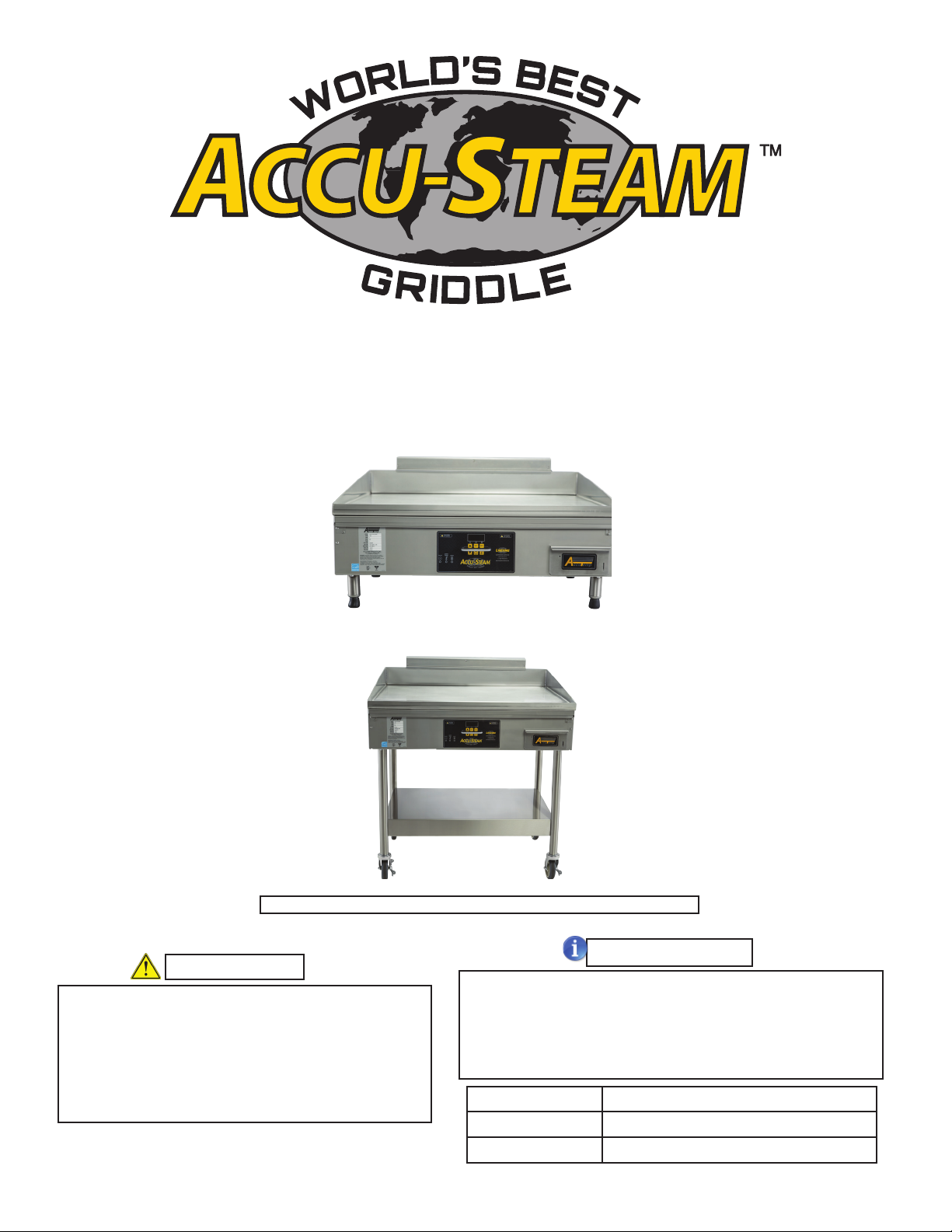
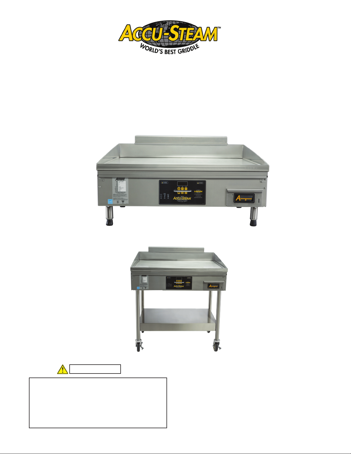
INSTALLATION/OPERATORS MANUAL
ACCU-STEAM GAS G2 GRIDDLE
MODELS
GGF24A
GGF36A
GGF48A
GGF24B
GGF36B
GGF48B
PGF24A
PGF36A
PGF48A
PGF24B
PGF36B
PGF48B
This manual should be retained for future reference
WARNING
Improper installation, alteration, adjustment,
service, maintenance or cleaning can cause
property damage,injury or death. Read
the installation, operational, maintenance
instructions thoroughly before installing,
servicing or operating this equipment.
MP5017-1605
AccuTemp Products, Inc. · 8415 North Clinton Park · Fort Wayne, IN 46825 ·800 210-5907 · accutemp.net
Record the serial number, model number
(identication decal located on the left side panel
of the commercial appliance) , voltage and the
install date. Please have this information when
calling for assistance.
Serial Number:
Model:
Install Date:
NOTE
Page 2

Page 3
IMPORTANT FOR YOUR SAFETY
The safety Instructions below should be posted in a prominent location as a reminder
of safe practices to follow in the event of an equipment or facility utility issue.
WARNING
In the event of a gas odor is detected, shutdown all appliances at the main shut-off valve and
contact the local gas company or gas supplier
WARNING
In the event of a power failure , do not attempt to operate this appliance
FOR YOUR SAFETY
Do not store or use gasoline or other
ammable vapors and liquids in the
vicinity of this or any other appliance
WARNING: Improper installation, alteration,
adjustment, service, cleaning or maintenance of
this commercial appliance could cause property
damage, serious injury or death.
Read and understand the installation, operational,
maintenance instructions before installing,
servicing, or operating this commercial appliance.
This manual should be retained for future reference
MP5017-1605
Accu-Steam™ Gas G2 Installation and Operators Manual
PAGE 1
Page 4

NOTICE
The State of California enacted the California Safe Drinking Water and Toxic Enforcement Act of
1986, (Prop. 65), which “prohibits any person in the course of doing business from knowingly and
intentionally exposing any individual to a chemical known to the State of California to cause cancer
or reproductive toxicity without rst giving clear and reasonable warning to such individuals.” The
Governor’s Scientic Advisory Panel added Carbon Monoxide to the list of hazardous chemicals
known to cause reproductive harm.
In order to establish full compliance with Proposition 65, a yellow warning label has been attached to
each gas red unit manufactured by AccuTemp Products,Inc.
Carbon monoxide would not be present in concentrations that would pose a “signicant risk” to the
consumer when the equipment is installed, operated and maintained as follows:
1. Installed in accordance with all local codes, or in the absence of local codes, with the current
2. National Fuel Gas Code Z223.1, latest addenda/NFPA 54 Natural Gas and Propane Installation
code , CSA B149.1 as applicable.
3. Installed under a properly designed and operating exhaust hood.
4. Connected to the type of gas for which the unit is equipped.
5. Proper appliance pressure regulator installed on the gas supply line and adjusted for the manifold
pressure marked on the rating plate.
6. Adequate air supply to the unit.
7. The equipment is operated in the manner intended using the proper utensil for that type of
appliance.
8. Keep the equipment clean and have it checked periodically.
9. Burner air adjustments, mechanical maintenance and repairs should be performed by qualied
service personnel.
MP5017-1605
Accu-Steam™ Gas G2 Installation and Operators Manual
PAGE 2
Page 5
TABLE OF CONTENTS
DESCRIPTION PAGE
Important for Your Safety 1
California Prop 65 2
Document History 3
Limited Warranty Policy 4
Safety Warnings 5-7
Warranty Registration Instructions 8
Installation/Operators Checklist and Warranty Registration Form 9-10
Installation 11-14
Operation 15-24
Cleaning 25-26
Troubleshooting 27-29
Planned Maintenance 30-33
Schematics 34-35
Specications 36-39
Technical Service Contact Information 40
DOCUMENT HISTORY
Current Revision Date Prior Revision Date
MP5017-1612 05/12/2016 N/A N/A
Initial Release
MP5017-1605
Accu-Steam™ Gas G2 Installation and Operators Manual
PAGE 3
Page 6

PRODUCT WARRANTY
U.S. & Canada Sales Only
LIMITED WARRANTY
One Year Parts and LaborOne Year Parts and Labor
AccuTemp Products, Inc. ( AccuTemp ) warrants that your AccuTemp equipment will be free of defects in
material and workmanship under normal use for a period of twelve (12) months from installation or fteen (15)
months from date of shipment from AccuTemp, whichever date rst occurs (the Warranty Period ). Registration
of AccuTemp equipment is required at time
of installation.
Damage to AccuTemp equipment that occurs during shipment must be reported to the carrier, and is not
covered under this warranty. The reporting of any damage during shipment is the sole responsibility of the
commercial purchaser/user of such AccuTemp equipment.
AccuTemp provides an active service department, which should be contacted and advised of service issues
regardless of warranty period.
During the warranty period, AccuTemp agrees to repair or replace, at its option, F.O.B. factory, any part which
proves to be defective due to defects in material or workmanship, provided the equipment has not been altered
in any way and has been properly installed, maintained, and operated in accordance with the instructions in
the AccuTemp Owners Manual.
During the warranty period, AccuTemp also agrees to pay for any factory authorized equipment service agency
(within the continental United States and Canada) for reasonable labor required to repair or replace, at our
option, F.O.B. factory, any part which proves to be defective due to defects in materials or workmanship,
provided the service agency has received advance approval from AccuTemp factory service to perform the
repair or replacement. This warranty includes travel time not to exceed two hours and mileage not to exceed
50 miles (100 miles round trip), but does not include post start-up assistance or training, tightening of loose
ttings or external electrical connections, minor adjustments, gaskets, maintenance, or cleaning. AccuTemp
will not reimburse the expense of labor required to replace parts after the expiration of the warranty period.
Proper installation is the responsibility of the dealer, owner-user, or installing contractor and is not covered
by this warranty. While AccuTemp products are built to comply with applicable standards for manufacturers,
including Underwriters Laboratories (UL) and National Sanitation Foundation (NSF), it is the responsibility of
the owner and the installer to comply with any applicable local codes that may exist.
AccuTemp makes no other warranties or guarantees, whether expressed or implied, including any warranties
of performance, merchantability, or tness for any particular purpose. AccuTemp s liability on any claim of any
kind, including negligence, with respect to the goods and services covered hereunder, shall in no case exceed
the price of the goods and services, or parts thereof, which gives rise to the claim. In no event shall AccuTemp
be liable for special, incidental, or consequential damages, or damages in the nature of penalties.
This constitutes the entire warranty, which supersedes and excludes all other warranties, whether written, oral,
or implied.
IMPORTANT
Improper installation can affect your warranty. Installation is the responsibility of the Dealer, Owner/
User or the Installation Contractor. See: Section One, Installation of the Owner s Manual.
For Service Call 800-480-0415 or email: service@accutemp.net
MP5017-1605
Accu-Steam™ Gas G2 Installation and Operators Manual
PAGE 4
Page 7
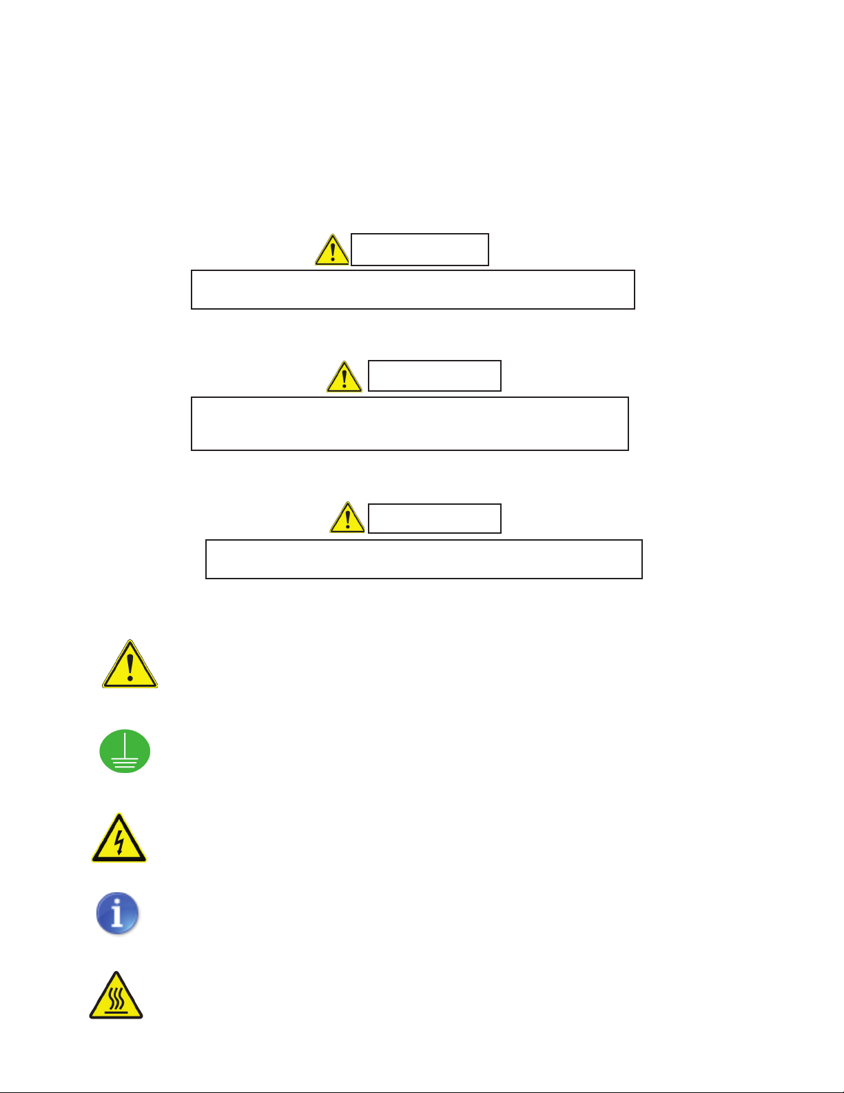
SAFETY WARNINGS
SYMBOL DEFINITIONS
Symbols are used to attract your attention to possible dangers. They are only effective if the
operator uses proper accident prevention measures. Some of the symbols are boxed text, while
other maybe just picture icons. Please give this information the respect they deserve for safe
operation.
DANGER
Indicates an imminently hazardous situation which, if not
avoided, will result in death or serious injury.
CAUTION
Indicates a potentially hazardous situation which, if not
avoided, could result in death or serious injury.
WARNING
Indicates a potentially hazardous situation which, if not
avoided, could result in minor or moderate injury.
ALERT - Noties the reader of an important message/warning,
usually a safety related message.
Earth Ground
Dangerous Voltage
INFORMATION - Noties the reader of important information that
may or may not be safety related.
MP5017-1605
Caution Hot Surface
Accu-Steam™ Gas G2 Installation and Operators Manual
PAGE 5
Page 8
IMPORTANT SAFETY INSTRUCTIONS
IMPORTANT: Read the following safety installation to avoid personal injury or death and to avoid
damage to the equipment or property
WARNINGS
Improper installation, adjustment, alteration,
service or maintenance can cause property
damage, injury or death. Read the installation,
operating and maintenance instructions
thoroughly before installing or servicing the
equipment.
To Prevent Electrical Shock, do not open
access panel. There are no usableserviceable parts inside. Request servicing
from a qualied service personnel.
A ve minute complete shutoff must be
observed before the appliance is relighted.
Intended for other than household use.
Plug commercial appliance into a properly
grounded electrical outlet of the correct
voltage, size and plug conguration. If they
do not match, contact a qualied electrician
to determine the proper voltage and size and
install the proper electrical outlet.
Do not connect to a circuit operating more
than 150V to ground
To avoid any personal injury or damage to
the unit do not pull the commercial appliance
by the power cord.
To prevent any injury, discontinue any use if
power cord is frayed or worn.
To prevent any injury or damage this
commercial appliance must be installed by a
qualied electrician.
To avoid any injury, turn the power off, unplug
from the power source and allow to cool
before performing any maintenance.
To avoid electrical shock or personal injury,
do not steam clean or use excessive water
on this commercial appliance.
This product has no “user” serviceable parts.
To avoid injury or damage to the commercial
appliance use only Authorized AccuTemp
Service Agents and Genuine Replacement
Parts when service is required.
Genuine AccuTemp Replacement Parts
are specied to operate safely in the
environments in which they are used. Some
aftermarket parts or generic replacements
parts do not have the same specications to
operate safely in AccuTemp equipment. It is
imperative that to use Genuine AccuTemp
Replacement Parts to avoid injury or damage
to the commercial appliance.
Always disconnect from power source before
cleaning or servicing.
Any ineld modication that bypass the built-
in safety features will result in personal injury
or death.
This commercial appliance must be properly
grounded, in accordance with all National,
State or local electrical codes.
This commercial appliance has a totally
unique design and is constructed unlike
any other griddle on the market today. Any
modication may permanently damage the
griddle.
This commercial appliance must be level
for proper operation and to reduce possible
damage to this commercial appliance.
This commercial appliance is heavy, for
safe handling, the installer should obtain
help as needed or employ appropriate
material handling equipment to remove the
commercial appliance from the skid and
move to the nal location in the building.
Temperatures in and around the commercial
appliance are very hot and can cause severe
burns.
MP5017-1605
Accu-Steam™ Gas G2 Installation and Operators Manual
PAGE 6
Page 9

IMPORTANT SAFETY INSTRUCTIONS
To avoid damage to the cooking surface
of this commercial appliance do not use
abrasive cleaners such as a griddle stone or
brick.
To avoid personal injury or damage to the
commercial appliance do not use a water jet
to clean this commercial appliance.
To avoid damage to the commercial
appliance do not leave a chlorine sanitizer
in contact with the stainless steel longer
than 10 minutes.
To avoid severe burns slowly remove
the grease reservoir to avoid spilling the
contents. It is recommended to let it cool
before removing.
To avoid damage to the commercial
appliance do not leave a chlorine sanitizer
in contact with the stainless steel longer
than 10 minutes.
To avoid severe burns slowly remove
the grease reservoir to avoid spilling the
contents. It is recommended to let it cool
before removing.
MP5017-1605
Accu-Steam™ Gas G2 Installation and Operators Manual
PAGE 7
Page 10
To register this AccuTemp product for warranty complete the following items:
1. Complete the Installation/Operational Checklist and Warranty Registration Form on pages 13-14.
Mail, fax or scan and e-mail the form to AccuTemp Products, Inc to the contacts listed for each
type on the form.
If you have any questions about warranty registration please contact our technical service group.
They are available 7 days a week from 7:00 am to 7:00 PM EST.
Toll Free 800 480-0415
Ofce 260 469-3040
Fax 260 469-3045
Email -Service service@accutemp.net
Email-Parts parts@accutemp.net
Web Site www.accutemp.net
MP5017-1605
Accu-Steam™ Gas G2 Installation and Operators Manual
PAGE 8
Page 11
Installation/Operational Checklist &
Warranty Registration Form
GAS ACCU-STEAM G2™
MP5019-1605
Page: 1
Store/Location:
Address:
Contact Name:
City:
Phone Number:
State: Zip:
Fax Number:
Email:
Model # Serial #
Name of Service/Installer Company:
Technician: Phone Number:
** AccuTemp Products, Inc. is not responsible for the installation and/or modifications to the electrical supply source. **
Failure to accurately complete and provide this Installation/Operational Checklist & Warranty
Registration Form to AccuTemp Products may delay or void future Warranty Service Calls.
Check-Off List
General :
Is the 120 VAC wall receptacle positioned in a low heat-zone?
placed as low as State & Local codes allow. Placement in high heat-zones like: just above, below, or beside the exhaust flue;
will cause service issues that will not be covered under the product warranty.
Is the griddle being installed at an altitude greater than 4,000 feet? Note: If the altitude is greater than 4,000 feet
above sea level, contact AccuTemp Technical & Customer Support Department to verify what the correct orifice sizes for the
pilot and main burners should be.
Is the griddle level, both side-to-side and front-to-back?
Note: It is recommended that the wall receptacle be
Yes No
Yes No
Yes No
If this is a table-top installation, have the (4) rubber foot tip/boots been installed?
Is there sufficient spacing to ensure maximum air flow for proper combustion?
Gas Connection :
Is a Quick Disconnect Fitting used?
Is a Commercial Grade Gas Hose used?
What is the diameter of Commercial Gas Hose or Piping connected to the Griddle?
Gas Pressure Readings (To be taken with all the gas equipment in the facility turned ON and operating) :
What is the Supply Gas Pressure (in "WC) at the gas inlet of the Griddle?
MP5017-1605
Accu-Steam™ Gas G2 Installation and Operators Manual
Yes No
Yes No
If yes: Is a restraining device installed?
If yes: What is the length of the hose?
Yes No
Yes No
Yes No
PAGE 9
FT
IN
"WC
Page 12
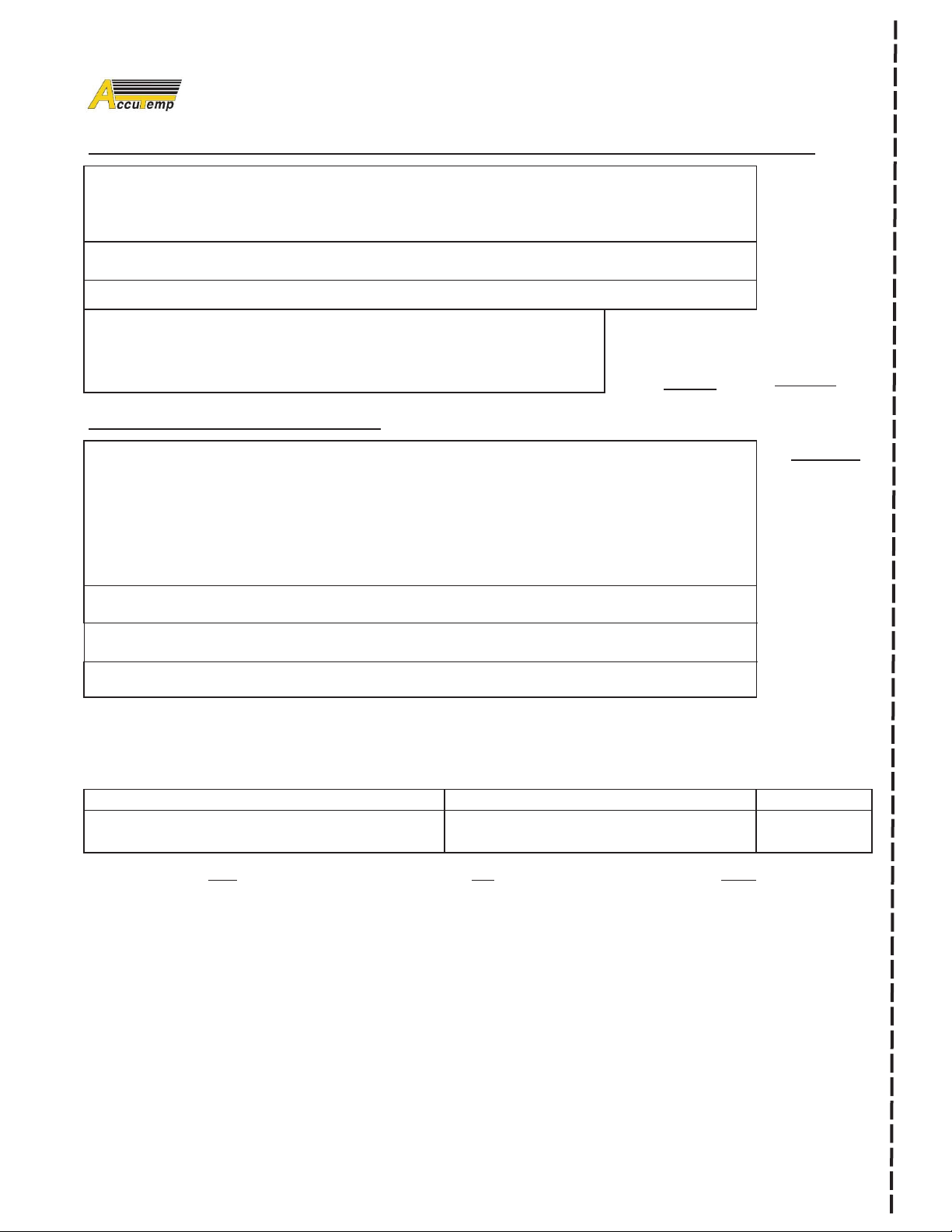
Installation/Operational Checklist &
Warranty Registration Form
GAS ACCU-STEAM G2™
MP5019-1605
Page: 2
Signature
Printed Name
Date:
Does the Supply Gas Pressure coming into the Griddle exceed 13"WC?
Gas Pressure Readings Continued (To be taken with all the gas equipment in the facility turned ON and operating) :
If yes: An external gas regulator needs to be connected to the supply gas line prior to the griddle connection?
Note: An external regulator should not be used unless the supply gas pressure is more than 0.5 psig (13"WC).
Using a 1/8" NPT fitting, has the Dual Regulating Valve been adjusted to 5"WC = Natural Gas (10"WC = Propane)?
Does the Flame Sense Signal reach a minimum value of 2.5 DC-µA or 30 DC-mV (could be higher)?
What is the maximum value of the Flame Sense Signal after the griddle reaches the
operating temperature?
the approved AccuTemp DC-mV Probes (PN: ATR-FT003); which can be purchased from
AccuTemp or an approved distributor.
Temperature & Operational Verification :
What is the customer's normal operating Thermostat temperature for the Griddle?
Using a weighted contact temperature probe with digital thermometer, does the surface temperature (°F)
match the normal operating temperature (°F) set on the Thermostat?
mercury thermometer.
Note: If the operating temperature is 250°F, then set Thermostat to 300°F and verify surface temperature. If the operating
temperature is 400°F, then set Thermostat to 400°F and verify surface temperature does not exceed 396°F on the high side
of the temperature drift/cycle.
Using a 9 square-grid-pattern on the griddle surface, are the surface temperatures consistent (±5°F)?
Does the Griddle heat light cycle OFF/ON once the surface temperature has reached the set temperature?
Does the unit operate properly for 15 minutes after the griddle has reached operating temperature?
I accept and submit this Installation/Operational Checklist & Warranty Registration Form as complete and accurate:
Note: A valid DC-milli-Volt (DC-mV) value can only be taken using
Note: DO NOT use an infrared or flat-top
DC-µA
or
Yes No
Yes No
Yes No
DC-mV
°F
Yes No
Yes No
Yes No
Yes No
Restaurant/Facility Manager Approval:
Mail Fax Email
AccuTemp Products, Inc
Attn: Warranty Administration
Attn: Warranty Administration
8415 North Clinton Park Dr.
Fort Wayne, IN 46825
MP5017-1605
Accu-Steam™ Gas G2 Installation and Operators Manual
260 469-3045
Attn: Warranty Administration
service@accutemp.net
PAGE 10
Page 13
MODEL G2 GAS
TABLE TOP & STAND
INSTALLATION INSTRUCTIONS
WARNING
Improper installation, alteration, adjustment,
service, maintenance or cleaning can cause
property damage,injury or death. Read
the installation, operational, maintenance
instructions thoroughly before installing,
servicing or operating this equipment.
MP5017-1605
Accu-Steam™ Gas G2 Installation and Operators Manual
PAGE 11
Page 14
INSTALLATION
TABLE TOP/STAND MODEL - GGF& PGF
Installation must conform with local codes , or in the absence of local codes, with the National Fuel Gas
Code, ANSI Z223.1/NFPA 54, or the Natural Gas and Propane Installation Code, CSA B149.1, as applicable.
WARNING
Improper installation, alteration, adjustment,
service, maintenance or cleaning can cause
property damage,injury or death. Read the
installation, operational, maintenance instructions
thoroughly before installing, servicing or operating
this equipment.
WARNING
Only a qualied service or electrician should
complete the installation to ensure that all
electrical and safety requirements are met and
that all wiring is installed as per all current
National, State and Local electrical codes.
WARNING
Always disconnect from power source before
cleaning or servicing.
WARNING
This commercial appliance is heavy. For safe handling,
the installer should obtain help as needed or employ
appropriate material handling equipment to remove
the commercial appliance from the skid and move
into the nal destination.
WARNING
Any in eld modications that bypasses the safety
features could result in injury or death.
CAUTION
IN-FIELD MODIFICATIONS
This commercial appliance has a totally unique
design and is constructed unlike any other griddle
on the market today. Any modication may
permanently damage the griddle.
TOOLS REQUIRED:
Spirit Level Manometer
Phillips Screw Driver Weighted Temperature Probe
Small Blade Straight Screw Driver Digital Temperature Meter
Digital Volt Meter with ability to read uAmps for
Flame Sense Measurement.
LOCATION AND PLACEMENT
The ACCU-STEAM™ gas griddle has been
designed to be placed on a commercial kitchen
counter-top, an AccuTemp griddle stand or
directly onto any at, level surface that will
support the commercial appliance weight.
The operating temperature ranges from 200°400°F (93°- 204°C). Since these temperatures
can also be found on surfaces around the
perimeter of this commercial appliance, care
should be given not to install next to or against,
objects or surfaces with a low melting or ash
point.
Accutemp Flame Sense Measurement Probes
P/N: ATR-FT003
CLEARANCES
Location
Back
Right Side
Left Side
SUITABLE FOR ALL INSTALLATION ON
LEVELING
The commercial appliance must be installed in
a level condition. An out-of-level condition may
cause uneven temperatures and in a severe
out of level condition damage to the commercial
Combustible
Construction
2 Inches 0 inches
1 Inch 0 inches
1 inch 0 inches
COMBUSTIBLE FLOORS.
Non-Combustible
Construction
MP5017-1605
Accu-Steam™ Gas G2 Installation and Operators Manual
PAGE 12
Page 15

INSTALLATION
appliance can occur. Use a spirit level resting
on the commercial appliance cooking surface to
ensure it is level front-to-back and left-to-right.
TABLE TOP
Install the (4) rubber foot tips provided with your
commercial appliance onto the four foot adjusters
of each of the commercial appliance legs. This
will keep the griddle from sliding on the countertop under normal use. Once the rubber foot tips
have been installed, adjust the four foot adjusters
up or down as needed to level the griddle side to
side and front to back.
ACCUTEMP STAND
If on an AccuTemp griddle stand with casters,
ensure that the oor surface is level and place
the two locking casters to the “on” position
and follow the leveling instructions to verify the
commercial appliance is level.
WARNING
When this appliance is installed with casters it
must be installed with the casters supplied. A
connector complying with either ANSI Z21.69 CSA 6.9. It must also be installed with restraining
means to the connector as specied in the
appliance manufacturer’s instructions.
ELECTRICAL SUPPLY
The ACCU-STEAM™ griddle has been designed,
manufactured and tested to meet or exceed the
demanding standards of safety set forth by ANSI
Z83.11. To to ensure that this high level of safety
is maintained in your installation, it is important
that you read and understand the following
information before attempting to plug in your
griddle.
ELECTRICAL REQUIREMENTS
Electrical requirements are listed on the
data plate located on the front right of the
control panel. All standard AccuTemp griddles
are supplied with a 6ft (1.83m) cord and
the appropriate UL listed plug that must be
connected to a 15 Amp (120Vac) or a 20 Amp
(208-240Vac) depending on the rating listed on
the data plate. Make sure that the voltage at your
supply receptacle is within ± 10 % of the voltage
listed on the griddle data plate. Connection to any
other voltage may cause damage to components
in the commercial appliance. The commercial
appliance plug must be used with the appropriate
receptacle.
Direct wiring will void the warranty.
GROUNDING INSTRUCTIONS
Grounding provides a path for electric current to
reduce the risk of shock. This product is equipped
with a power cord having a grounding conductor
and a grounding plug. The plug must be plugged
into a grounded receptacle that is installed and
grounded in accordance with local codes, or in
the absence of local codes, with the National
Electric Code, NFPA 70, or the Canadian
Electrical Code, CSA22.2, as applicable.
Under no circumstances shall the grounding
or prong of the plug be cut off or bent to t a
receptacle other than the one supplied. Do not
use any adapters to t the receptacle.
GAS CONNECTION
This appliance has been manufactured for use
with the type of gas indicated on the data plate. If
the locations gas supply does not match the gas
indicated on the equipment data plate. Contact
AccuTemp Products Technical Service at (800)
480-0415
All gas connectors must be in accordance with
the local code, State and National Fuel Federal
Gas Codes, ANSI Z223.1
The equipment should have a separate gas
shutoff valve (not supplied) installed in the
equipment supply line. A 1/2” inside diameter
or larger gas supply line or an ANSI approved
commercial exible gas hose that the inside
diameter is 1/2” or larger this to insure adequate
volume of gas for the equipment. The facility
supply manifold and regulator must be sized to
the load of all the appliances connected to it.
If other appliances are connected to the same
MP5017-1605
Accu-Steam™ Gas G2 Installation and Operators Manual
PAGE 13
Page 16

supply line as this equipment the gas load must
be calculated together to properly size the supply
line and for the safety of this equipment.
the Accutemp Technical Service. You will need
to provide elevation and heat content of the local
gas.
The appliance and its individual manual shutoff
valve must be disconnected from the gas supply
piping system during any pressure testing of that
system at test pressures in excess of 1/2” psi (3.5
kPa).
The appliance must be isolated from the gas
supply piping by closing its individual manual
shutoff valve during any pressure testing of the
gas supply piping system at test pressures equal
to or less than 1/2 psi (3.5 kPa)
If the appliance is on an AccuTemp stand with
casters or table with casters. the installation will
be made with a connector that complies with
the Standard for Moveable Gas Appliances,
ANSI Z21.69·CSA 6.16 and a quick-disconnect
device that complies with the Standard for Quick-
Disconnect Devices for Use With Gas Fuel, ANSI
Z 21.41 · CSA 6.9.
Adequate means must be provided to limit the
movement of the appliance without depending
on the connector and the quick-connect device
or its associated piping to limit the appliance
movement.
This appliance has an integral gas regulator that
is factory set for the gas type and pressure listed
on the appliance data plate.
An external gas pressure regulator is not
required if the gas pressure is under 1/2” psig
(13” water column).
Initial Gas Adjustment
This equipment has an integral gas pressure
regulator in the gas control valve that requires a
minimum of 7” water column for natural gas and
12” water column for propane at the inlet which
will allow the valve to be adjusted to the correct
equipment pressure of 5” water column for
natural gas and 10” water column for propane at
the outlet of the valve with the burners active.
If the griddle is above a 2000 feet elevation verify
that the orices are sized correctly to elevation
and the heat content of gas. You may need to
contact your gas supplier for this information.
If you are unsure of the orice size please contact
Control Valve with Internal Pressure Regulator
Gas Pressure Adjustment
Screw
If any of the installation instructions are not
completely understood contact the AccuTemp
Technical Service department before attempting
to start the appliance.
Use a 1/8” NPT Barbed Pressure Tap to verify pressure
setting.
MP5017-1605
Accu-Steam™ Gas G2 Installation and Operators Manual
PAGE 14
Page 17

OPERATION
MP5017-1605
Accu-Steam™ Gas G2 Installation and Operators Manual
PAGE 15
Page 18

OVERVIEW OF OPERATION
INTRODUCTION
The ACCU-STEAM G2™ griddle is constructed and uses technology like no other griddle in the
world. The stainless steel cooking surface is heated by steam. The griddle steam chamber requires
no additional liquid or maintenance. A temperature sensor to sense temperature and an overtemperature safety shutdown system are part of the griddle assembly. At temperatures below 212°F
(100°C), the chamber is actually in a vacuum, similar to that of a canning jar. At temperatures
above 212°F (100°C), the chamber operates under pressure. The temperature sensor senses
the temperature of the steam and reports this data to the temperature control electronics, which
energizes the heating system. This system maintains the griddle cooking surface temperatures to
within ± 5°F (2.7°C) over the entire cooking surface and provides a near instant temperature recovery,
even in the same spot on the griddle, when turning food in place. (See Fig. 1)
MP5017-1605
Fig. 1
Accu-Steam™ Gas G2 Installation and Operators Manual
PAGE 16
Page 19

OVERVIEW
Stainless Steel Cooking Surface
Overll Grease Drawer Hole
Data Tag
Display/Operational Keypad
Grease Drawer
Adjustable Bullet Feet
Fig. 2
Data Tag
MP5017-1605
Operation/Fault Indicators
Display/Operational Keypad
Tech Support Contact Info
Fig. 3
Accu-Steam™ Gas G2 Installation and Operators Manual
PAGE 17
Page 20

Overview Digital Temperature Control
OPERATION
The commercial appliance digital temperature control is easy to operate and requires lile
customer interface.
OPERATOR DISPLAY AND KEYPAD
OPERATOR DISPLAY
200F
LED 1
PROGRAM KEY
PROGRAM KEY
LED 3
LED 2
PRESET TEMP 1 KEY
PRESET TEMP 2 KEY
TEMPERATURE
DISPLAY KEY
ON/OFF
KEY
Fig. 4
MP5017-1605
Accu-Steam™ Gas G2 Installation and Operators Manual
PAGE 18
Page 21

General
OPERATION
This commercial appliance has a digital control temperature board that has two modes of
operation.
• Operational Mode
• Manager Mode
Operational mode is the most used mode and
the commercial appliance operates as the
keyboard overlay indicates during day to day
product production. (See Fig X)
Operational Mode Key Functions
ON/OFF Key - Dual Function Key; In the off
mode when pressed it turns on the griddle.
When on pressing and holding the key for ve
seconds turns the commercial appliance off.
Up Arrow Key - This key when pressed will
increase the set cooking temperature.
Down Arrow Key - This key when pressed
will decrease the set cooking temperature.
PRESET TEMP 1 Key - When pressed
and held for three seconds the system will
select the preset set temperature that was
set previously or the factory default of 375°F.
LED 2 will ash and the display will show the
current temperature and increase or decrease
depending on the set temperature until it
has reached the set preset temperature for
that preset key and then go solid and the set
display temperature will remain at the set
temperature until the commercial appliance
is turned off and back on. As the temperature
cools or product is added LED 2 will ash
indicating that the heating system is on and
will go solid when the set temperature is
reached.
has reached the set preset temperature for
that preset key and then go solid and the set
display temperature will remain at the set
temperature until the commercial appliance is
turned off and back on. As the temperature
cools or product is added LED 3 will ash
indicating that the heating system is on and
will go solid when the set temperature is
reached.
Display Temperature Key-When
pressed displays the current temperature
of the cooking surface.
Manager Mode Programming
Prior to using the commercial appliance a few
operational items need to be determined.
• Default set temperature
• Preset 1 set temperature
• Preset 2 set temperature
• Operator lockout of set temperatures or “on
the y” temperature set
Default Set Temperature - is the temperature
that the commercial appliance will heat up to
when turned on.
Preset 1 Set Temperature - is an alternative
set temperature that the commercial appliance
will heat up to when activated from the keypad.
Preset 2 Set Temperature - is an alternative
set temperature that the commercial appliance
will heat up to when activated from the keypad.
Set Temperature Lockout - If turned on
in the manager mode it will lock in the set
temperatures that were last saved in memory.
If not set to active the set temperatures can be
set lower or higher than the last saved value.
PRESET TEMP 2 Key - When pressed and
held for three seconds the system will select
that preset set temperature that was set
previously or the factory default of 400°F.
LED 3 will ash and the display will show the
current temperature and increase or decrease
depending on the set temperature until it
MP5017-1605
Accu-Steam™ Gas G2 Installation and Operators Manual
PAGE 19
Page 22

OPERATION
070F
375°F
350F
Fig. 5
Press the ON/OFF switch (See FIG 1) and
the griddle will start to pre-heat and LED 1 will blink
Any time the commercial appliance is turned on it
will operate and heat to the default set temperature.
(Factory default is 350°F.)
The display will show the current temperature until
the set temperature is met, then LED 1 will go solid.
(See FIG 2) The display will remain at the set
temperature unless the griddle is turned off and
back on.
As with any cooking commercial appliance the
temperature will drop as new product is added and
the griddle will activate the heating cycle. LED 1
will blink until the set temperature is reached and
then go solid. The display will remain at the set
temperature unless the commercial appliance is
turned off and back on.
Fig. 6
PRESETS
Press the ON/OFF switch (See FIG 1) and the
griddle will start to pre-heat and LED 1 will blink .
Press and hold any PRESET KEY or
for three seconds or until the LED 2 or LED 3 blinks.
The selected preset LED will blink and the display will
show the current temperature and increase or decrease
depending on the set temperature until it has reached
the set preset temperature for that preset key and then
go solid and the set display temperature will remain at
the set temperature until the griddle is turned off and
back on. This cycling of the LED will continue as long
as the commercial appliance is on.
The factory defaults for the preset keys are:
400°F.
MP5017-1605
Please use caution as temperatures on and around the griddle
cooking surface could cause severe burns.
Accu-Steam™ Gas G2 Installation and Operators Manual
PAGE 20
Page 23

DIGITAL TEMPERATURE CONTROL QUICK REFERENCE
MODE LED Indicators DISPLAY NOTES
Off All LED’s are off when
powered down.
Warm Up / Cool
Down
Ready Mode LED above the
Set Temperature
(On the y)
Select Preset
Temperature
Set Preset
Temperature
Blinking LED
above the selected
temperature key (LED
1, 2 or 3). If default
condition then LED 1.
If Preset 2 is selected
then LED 3 If Preset 1
then LED 2
selected key will be
ON
All indicator LEDs
blinking
Selected Preset
indicator LED blinking
All indicator LEDs
blinking. Then the
selected preset key
will blink for 3 -5
seconds.
Off when powered down.
When powered On, the
controller would FLASH
at a 1 Hz rate the current
set temperature for 5
seconds. After this period
the controller would go
to Warm Up / Cool Down
Mode.
Actual temperature when
no keys depressed, or set
temperature of
Preset/Manual key when
key is held.
Cook set point temperature
when no keys depressed,
or set temperature of
Preset/Manual key when
key is held.
Set Point Value To set temperature, press either the UP
Set Point Value To select an alternate preset temperature, if
Set Point Value Use the same process to change the
To turn unit on: depress the On/Off key.
To turn off the unit, disable outputs, save
the current set point temperature (see
details in “Other Features”) and turn off the
display: press and hold the On/Off key for
approximately three seconds.
Upon power-on or whenever another
temperature setting is made, the unit will
enter this mode and will exit this mode only
when the actual temperature has regulated.
Once has regulated, the indicator LED above
the selected key will go to solid ON and the
set point value will be displayed.
arrow key or the DOWN arrow key and hold
for approximately 3 seconds. The controller
will load and display Default Cook Temp
and enter set temperature mode. Press the
UP arrow key to increment or the DOWN
arrow key to decrement from the current
temperature setting. Wait for ve seconds.
If there are no other key presses, the unit will
auto start to the new setting. Press the On/
Off key to exit without saving.
in Preset Temp 1 setting, press Preset Temp 2
key and hold for approximately 3 seconds. If
in Preset Temp 2 setting, press Preset Temp 1
key and hold for approximately 3 seconds.
temperature as detailed in Set Temperature
(On the y) to adjust the Set Temperature.
Once the correct temperature is displayed,
and before the ve second time out, press
and hold the Preset Temp 1 key or the Preset
Temp 2 key to save the displayed value to
the desired preset key and to exit this mode.
Press the On/Off key to exit without saving.
Default values for Preset 1 = 375°F. Default
values for Preset 2 = 400°F
MP5017-1605
Accu-Steam™ Gas G2 Installation and Operators Manual
PAGE 21
Page 24

DIGITAL TEMPERATURE CONTROL QUICK REFERENCE
MODE LED Indicators DISPLAY NOTES
Display
Temperature
Mode
User Lockout
Mode
(Managers Mode)
Current Temperature
function LED on
All LEDS on solid Set Point Value To Set USER LOCKOUT mode, press and
Actual temperature Pressing the DISPLAY TEMP key will display
the current actual temperature when the unit
is in Ready Mode.
hold the On/Off key and the DISPLAY TEMP
key for approximately 4 seconds while the
controller is ON. After 4 seconds, the USER
LOCKOUT parameter will toggle and the display will show either “Loc” or “ULoc”. When
buttons are released, the controller will store
the new USER LOCKOUT parameter value
into NVM.
MP5017-1605
Accu-Steam™ Gas G2 Installation and Operators Manual
PAGE 22
Page 25

OPERATION
FIRST STEP
It is recommended that you clean your
ACCU-STEAM™ griddle thoroughly before using
it for the rst time. To clean the griddle surface,
just simply wash the cooking surface down with
a solution of mild soap and water, then rinse
thoroughly with clean water and wipe dry with a
clean towel.
WARNING
Please use caution as temperatures on and around
the griddle cooking surface could cause severe
burns.
SEASONING
Once the cooking surface has been cleaned,
turn the commercial appliance on via the digital
control key pad and set temperature to 200°F.
(93°C), and allow the griddle cooking surface to
heat for 10 minutes. Using a high temperature
oil, such as Pan and Grill Shortening™, Whirl™
or equivalent, pour enough to cover the entire
griddle surface. Do not use standard vegetable
oil to season the griddle cooking surface. It
may cause food to stick and result in improperly
cooked food. Work this seasoning oil into the
griddle surface with a regular heavy-duty scrub
pad for about 5 minutes, making sure that you
scrub the seasoning oil over the entire griddlecooking surface. After the entire griddle surface
has been scrubbed with seasoning oil for 5
minutes, simply wipe or squeegee off excess oil
from griddle surface. Your griddle is now ready to
use!
If you use chemicals to clean your griddle
periodically or on a schedule, you may need
to repeat this process after the use of these
chemicals.
griddle will be preheated when the selected set
temperature is displayed and the corresponding
LED goes solid. Please use caution as
temperatures on and around the griddle cooking
surface could cause severe burns.
COOKING
Begin cooking only after the griddle has been
preheated to the desired temperature. Please
note these facts:
• You can cook all the way to the edges of the
cooking surface because the temperature
does not very across the entire cooking
surface.
• You can turn the product to the same spot
because the cooking surface has near
instant heat recovery.
• It will always cook the same, regardless of
product load or surface coverage.
Accurate Cooking Temperatures
Because of the inaccurate surface temperatures
and long recovery times common with other
griddles cooking surfaces. It is doubtful you were
cooking at the set temperature or the temperature
you wanted. Adjust the temperature on the
Accu-Steam ™griddle and it will not change or
vary by the location on the griddle surface. There
are no hot or cold zones.
CHECKING SURFACE TEMPERATURE
This griddles digital temperature control and
temperature sensor are more accurate than any
other device to measure the surface temperature.
Any other digital device may show a difference.
The important use of the external temperature
measuring device is to ascertain that the
temperatures are within ±5°F across the entire
surface of the griddle.
PREHEATING
Press the ON/OFF and set the desired
temperature. The griddle will increase its surface
temperature at an average rate of 15° F (8°C)
per minute. It takes approximately 25 minutes
to raise the griddle from room temperature to its
maximum temperature of 400° F (204°C). The
MP5017-1605
Accu-Steam™ Gas G2 Installation and Operators Manual
Due to the construction material of the cooking
surface an infrared temperature probe can’t
be used. The proper measurement tools to us
is a weighted temperature probe and digital
temperature meter. (See Fig. X3)
PAGE 23
Page 26

OPERATION
It is normal for the heat light to cycle on and off.
This light indicates when the heaters are
energized. This will be more noticeable as you add
cold product to the cooking surface. You will soon
notice how little they are energized to maintain
perfect surface temperatures on your griddle.
Weighted Temperature Probe
Fig. 7
NOTE
Do not use an infrared or a mechanical temperature
gauge to measure the surface temperature of the
griddle as it will not be accurate and will provide a
false temperature reading of the cooking surface
temperature.
Digital Temperature Reading Device
WARNING
The grease can contents could cause severe burns. Slowly remove the grease container from the commercial appliance to avoid spilling the contents
Grease Container
The grease container is located on the front
right side of the commercial appliance and has
a gripping handle on the front and the inside
middle to assist in safely managing the hot
contents. Use caution when emptying the grease
pan as contents in this container could cause
severe burns. The grease container should be
checked periodically and emptied as necessary
to prevent an overow or dangerous condition.
To assist in indicating an overll condition a hole
located on the front of the container will allow
grease to escape when overlled.
WARNING
Allow the grease container contents to cool
below 140°F before removing. Be careful not
to spill the contents of the grease container as
it can cause a slipping condition which could
cause a personal injury
MP5017-1605
Accu-Steam™ Gas G2 Installation and Operators Manual
PAGE 24
Page 27

CLEANING
WARNING
Always disconnect from power source before
cleaning or servicing.
WARNING
If the cooking surface of the commercial appliance
has standing grease and the griddle is at a
high temperature using water or ice can cause
the grease to splatter and cause skin burns.
WARNING
The grease can contents could cause severe
burns. Slowly remove the grease can from
the griddle to avoid spilling the contents.
MP5017-1605
Accu-Steam™ Gas G2 Installation and Operators Manual
CAUTION
Do not use a water-jet to clean this
commercial appliance as it can
harm the electronic components.
CAUTION
Do not use a commercial appliance
stone or brick to clean griddle cooking
surface. Only use a fabric scrub pad.
PAGE 25
Page 28

DAILY CLEANING
Cleaning the cooking surface during the work
shift can be performed with a sharp scraper.
When heavy cleaning at the end of a shift or
periodically through the day is needed, the
following is recommended:
• Empty the grease pan as often as needed
and always prior to end of shift cleaning.
• Turn the griddle off and allow it to cool
to between 220°F and 240°F (104°C
and 116°C). Scrape off heavy deposits
and remove any standing grease before
proceeding with the cleaning process.
• Use water, ice and/or griddle cleaner as
needed. For example, the 3M ScotchBrite™ Quick Clean Griddle System
provides the Scotch-Brite polishing
pads, quick clean liquid, pad holder and
squeegee. Clean-up is very easy using
these tools with the quick clean liquid,
water, ice or combinations of these liquids.
Seasoning the cooking surface after the
daily cleaning is recommended.
• After the non-cooking surfaces are cool to
the touch. Empty the grease pan and wash
with a mixture of dish detergent and clean
water and dry with a clean dry cloth.
• Clean the non-cooking surfaces with a
damp cloth and dry with a clean dry cloth.
Use a high quality stainless steel cleaner
on a clean cloth to reduce grease buildup.
Follow the manufacturers instructions
located on the cleaner.
• It is recommended that a high quality
stainless steel polish be used on the
non-cooking surfaces as the last step in
keeping surfaces in new like condition and
lengthen the usable life of this commercial
appliance. Follow the manufacturers
instructions located on the polish.
Cleaning the Cooking Surface
Step 1
Scrape off Heavy Deposits
Step 2
Cool griddle to 220°F and apply
water or ice. Use a long handled
nonmetallic scrub to scrub the
cooking surface.
Step 3
Add additional water or ice and
using a long handle squeegee and
pull to the grease trough.
MP5017-1605
Accu-Steam™ Gas G2 Installation and Operators Manual
PAGE 26
Page 29

SERVICE & TROUBLESHOOTING
WARNING
Always disconnect from power source before
cleaning or servicing.
WARNING
Any in-eld modication that bypass the built in safety
features of this commercial appliance will result in
death or serious injury.
WARNING
Use of any replacement parts other than those supplied
by AccuTemp can cause injury to the operator or damage
the commercial appliance and voids all warranties
MP5017-1605
Accu-Steam™ Gas G2 Installation and Operators Manual
WARNING
There are no user-serviceable parts. To prevent
electrical shock do not open the access panel
covers
NOTE
Service should be completed by AccuTemp
authorized service groups. Service completed
by unauthorized groups will void all factory
warranties.
NOTE
AccuTemp Technical Service must be contacted for
all warranty service requests. If not the warranty claim
maybe denied.
PAGE 27
Page 30

SERVICE AND TROUBLESHOOTING
An AccuTemp Products, Inc. Technical Service Technician is available:
Monday thru Sunday, 7:00am to 7:00pm EST.
Toll Free 800 480-0415
Ofce 260 469-3040
Fax 260 469-3045
Email -Service service@accutemp.net
Email-Parts parts@accutemp.net
Web Site www.accutemp.net
WARRANTY SERVICE PROCEDURE
• Contact the AccuTemp Technical Service group for all warranty service requests.
• Be prepared to supply the serial number, address, location phone and contact for the location.
• Be prepared to complete a few simple tasks to help evaluate the problem.
• If the problem requires service at the location the AccuTemp Technical Service group will dispatch
the nearest authorized service agent.
NOTE
Service should be completed by AccuTemp
authorized service groups. Service completed
by unauthorized groups will void all factory
warranties.
AccuTemp Technical Service must be contacted for
all warranty service requests. If not the warranty claim
maybe denied.
NOTE
MP5017-1605
Accu-Steam™ Gas G2 Installation and Operators Manual
PAGE 28
Page 31

SERVICE AND TROUBLESHOOTING
BASIC TROUBLESHOOTING
Griddle will not turn on
• Make sure the griddle is plugged in.
• Check the facility circuit breaker (or
fuse) supplying the unit
Heat light will not come on
• Make sure the griddle is not hotter than
the temperature you have it set for. If
you have turned down the temperature
of the griddle, the heat light will not
come on again until the cooking
surface drops below the temperature
you have set.
• See if the heat light is coming on
intermittently. While operating in
a normal condition, the heat light
cycles on and off periodically when at
temperature.
Uneven or inaccurate surface temperatures
• Verify griddle is level front to back and
side to side.
• Verify the surface temperature with
an accurate digital surface probe
thermometer.
• Use of an infrared or mechanical
thermometer will not give an accurate
reading of the griddle surface
temperatures.
• Contact AccuTemp Technical Service
for additional instructions.
Error 002
• Open Temperature Sensor
Fault Indicators
FAULT - (Gas Only) When this error is lit an
ignition failure of the appliance has occurred.
To correct turn the appliance off and wait 1
minute and then turn the appliance back on.
OVERTEMP - When this error is lit an
overtemp condition was sensed and will turn
off the appliance power. To correct turn the
appliance off and then back off to reset.
Unit will not turn off
• This symptom, which is extremely rare,
indicates a serious control malfunction.
• Turn off the griddle’s electrical supply
at the source and contact AccuTemp
Technical Service for additional
Instructions.
• Make sure to hold the On/Key for 3
seconds or until the display turns off
Preset Temperatures are not working•
• Make sure to hold the On/Key until the
display turns off.
Error 001
• Shorted Temperature Sensor
MP5017-1605
Accu-Steam™ Gas G2 Installation and Operators Manual
PAGE 29
Page 32

Page 33

PLANNED MAINTENANCE
WARNING
Always disconnect from power source before
cleaning or servicing.
WARNING
Any in-eld modication that bypass the built in safety
features of this commercial appliance will result in
death or serious injury.
WARNING
Use of any replacement parts other than those supplied
by AccuTemp can cause injury to the operator or damage
the commercial appliance and voids all warranties
MP5017-1605
Accu-Steam™ Gas G2 Installation and Operators Manual
WARNING
There are no user-serviceable parts. To prevent
electrical shock do not open the access panel
covers
NOTE
Service should be completed by AccuTemp authorized
service groups. Service completed by unauthorized
groups will void all factory warranties.
NOTE
AccuTemp Technical Service must be contacted for
all warranty service requests. If not the warranty claim
maybe denied.
PAGE 29
Page 34

NOTE
It is recommended that you contact your Accutemp authorized service provider
to setup a planned maintenance program to keep your appliance operating in the
most efcient manner. Accutemp recommends a minimum of a yearly schedule.
PM DESCRIPTIONS GENERAL
ITEMS
Verify that the appliance is level and properly located under
the hood.
Verify that the temperature controller is working properly. X X X
Verify that there are no puncture or rips in the overlay of the
controller
Check that the splash shield at the top of the control panel
is under the rail provided. If not water and or grease can
migrate and cause possible damage to the internal electronic
components.
Inspect the control compartment for foreign particulate and
any loose wiring connections.
Daily. A back draft diverter has been installed at the factory
this will keep scraping from spatulas from dropping down the
ue and will provide addition protection from back drafts that
can effect stand-by burner operation. Check that ue has
not been pushed in resulting in an uneven opening across
the ue passage. Pull ue out so that ue opening is even
across width of appliance.
Verify the operation and condition of the igniter probe
assembly. Probes should be cleaned with a wire brush and/
or emery cloth. Caution: DO NOT use any abrasive that
contains aluminum oxide. This will leave a coating on
the ame sensor that could cause the unit not to light.
Clean all gas orices, making sure the orice is clear and
unobstructed. It may be necessary to a drill the same size
of the orice, if very soiled. Note: It may be necessary to
clean the pilot orice more often.
Inspect the burner venturi tubes for foreign particulate. Wipe
out with a mild detergent and warm water and rinse with
clean water.
Inspect combustion chamber and the burner tiles. If water
stains are present on tiles check that tiles have no cracks
and haven’t sunk into the burner. Replace burners if this
condition is present.
Inspect the ignition wire harness for any evidence of high
temperature degradation or grease build-up on harness
connector. Spray contact cleaner into white connector and
clean mating connector imbedded in ignition module.
Verify main burner regulator pressures are correct. X X
Verify ame sense operation X X
X X X
BIANNUAL
ITEMS
X X
X X
X X
X X
X X
X X
X X
X X
ANNUAL
ITEMS
X
MP5017-1605
Accu-Steam™ Gas G2 Installation and Operators Manual
PAGE 30
Page 35

NOTES:
1. AccuTemp-approved service providers should complete these PM tasks.
2. General PM items should be completed at the same time as biannual or annual PM items are
completed.
Igniter Assembly
The igniter probe ignites the main burners and depending on the kitchen cooking environment,
geographic location and cleaning solutions employed, the ventilation airow can deposit airborne
material onto the probes, causing the pilot burner to have difculty lighting.
Required Material: nut-driver/wrench, Phillips screwdriver, stainless steel brush, Accutemp adaptor
part number. ATR-FT003 and a digital voltmeter able to read dc millivolts or dc uAmps
Tasks:
1. Remove the retaining screws and remove the probe assembly.
2. Brush all probes to remove foreign material.
3. Re-install the probe assembly and verify operation.
4. Check millivolts by grounding black lead of adaptor to the chassis, then inserting the red lead into
socket of the connector containing the orange lead to the ame sensor. Reading should be above
30 millivolts.
Flame Sense Assembly
The igniter probe ignites the main burners and depending on the kitchen cooking environment,
geographic location and cleaning solutions employed, the ventilation airow can deposit airborne
material onto the probes, causing the pilot burner to have difculty lighting.
Required Material: nut-driver/wrench, Phillips screwdriver, stainless steel brush, Accutemp adaptor
part number. ATR-FT003 and a digital voltmeter able to read dc millivolts..
Tasks:
1. Remove the retaining screws and remove the probe assembly.
2. Brush all probes to remove foreign material.
3. Re-install the probe assembly and verify operation.
4. Check millivolts by grounding black lead of adaptor to the chassis, then inserting the red lead into
socket of the connector containing the orange lead to the ame sensor. Reading should be above
30 millivolts.
Orices and Burner Venturi
Pilot and main burner orices can collect dust and grease over time in any kitchen environment.
If this material blocks the orices, the appliance will be less efcient and can cause intermittent
operation or complete shutdown.
MP5017-1605
Accu-Steam™ Gas G2 Installation and Operators Manual
PAGE 31
Page 36

Depending on the size of your appliance, there are a minimum of 2 and a maximum of 3 orices that
require inspection and cleaning. Each main burner will have an orice.
Required Material: towel, soap and warm water, stiff wire smaller than the orice nozzle or orice drill
of the same size hole.
Tasks:
1. Dampen a towel with the soap and water solution and clean the orice.
2. Take the stiff wire or orice drill and insert it into the hole in the center of the orice and run it back
and forth, making sure all foreign material is removed.
3. Clean the burner venturi opening so that it is free of any collected dust, grease and any other foreign substances.
Gas Pressures
The appliance requires the proper gas pressure setting to operate properly. All pressure readings
should be taken after the unit has reached a temperature of at least 200°F and while it is running to
ensure proper ow rates.
Required Material: manometer, 1/8” NPT barbed hose tting one 2 inch long lengths of
approximately. 1/8” diameter exible rubber hose (closed on one end).
Tasks:
1. Verify pressure regulator vent are clear before making any pressure adjustments. Remove the
1/8” NPT pipe plug from the main gas valve and install the 1/8” NPT barbed hose tting. Tighten
and mount one length of the rubber hose.
2. Allow the appliance to heat up to al least 200°F. First, check the main burner regulator pressure.
Remove the rubber hose and replace with the manometer tube. The pressure should be 5” WC
for natural gas and 10“WC for propane. If the pressure does not meet or exceed these values,
remove the cap on the main burner pressure regulator and adjust it to the necessary value.
3. Replace the hose ttings with original pipe plugs.
4. Check for gas leaks.
MP5017-1605
Accu-Steam™ Gas G2 Installation and Operators Manual
PAGE 32
Page 37

SCHEMATICS
WARNING
Always disconnect from power source before
cleaning or servicing.
WARNING
Any in-eld modication that bypass the built in safety
features of this commercial appliance will result in
death or serious injury.
WARNING
Use of any replacement parts other than those supplied
by AccuTemp can cause injury to the operator or damage
the commercial appliance and voids all warranties
MP5017-1605
Accu-Steam™ Gas G2 Installation and Operators Manual
WARNING
There are no user-serviceable parts. To prevent
electrical shock do not open the access panel
covers
NOTE
Service should be completed by AccuTemp authorized
service groups. Service completed by unauthorized
groups will void all factory warranties.
NOTE
AccuTemp Technical Service must be contacted for
all warranty service requests. If not the warranty claim
maybe denied.
PAGE 33
Page 38

ACCUSTEAM G2 GAS SCHEMATIC
OPTIONAL
REMOTE
TIMER
AT2T-2912-1
AT2T-3912-1
120V-240V
ACCU-STEAM G2 GAS
GRIDDLE
8415 N. Clinton Park
Fort Wayne, IN 46825
AccuTemp Products, Inc.
G2 GRIDDLE
PV
MV
GAS VALVE
38V
YEL
ZR1
ZR2
HV IGNITOR
38V
SPARK
MODULE
ORN
1 2 3 4 5 6
RED
BLU
GRN
7
COM
8
N.O.
BLU
6
5
COM
RLY 2
DC COIL
2
4
1
3
N.O.
N.C.
N.C.
SCHEMATIC,
AT2T-3912-1 Rev A
BURNER
YEL
ISSP
1 2 3 4 5
J3
PRTD
1000O
1 2
INPUT
SENSOR
DIGITAL
CONTROLLER
GRY
J7
ON/
OFF
ORN
BRN
VIO
WHT/BRN
WHT/GRAY
100 O
PRTD
BRN
VIO
YEL
WHT/BRN
GND
1 2 3 4 5 6
+24V
J2
INPUT
1 2
POWER
HIGH LIMIT
CONTROLLER
L1 L2 N.C. N.O. COM *RTD* RESET
BRN
BRN
TEMP
OVER
RED
MP5017-1605
REDRED
123
TIMER
GRN
WHT
BLK
2
1
FAULT
VIO
YEL
GRN
1
2
3
J1
YEL
BLU
4
YEL
COM
24V
120V
208V
240V
.75 A
F2
.75 A
WHT BLK
F1
Accu-Steam™ Gas G2 Installation and Operators Manual
HEAT
YEL
BLU
IGN FAULT
WHT
BLK
WHT
RED
ORN
PAGE 34
Page 39

INFORMATION
IMPORTANT SERVICE INFORMATION
Must contact AccuTemp Products Technical Service for all
warranty service requests for authorization and dispatch of
authorized service providers.
INFORMATION
IMPORTANT SERVICE INFORMATION
AccuTemp Product, Inc. Technical & Customer Support Technician is
available Monday thru Sunday, 7:00am to 7:00pm EST
800 480-0415 or 260 469-3040
TECHNICAL SERVICE
TOLL FREE 800 480-0415
PHONE 260 469-3040
FAX 260 460-3045
E-MAIL service@accutemp.net
Hours of Operation 7:00 am - 7:00 pm EST - 7 days a week
MP5017-1605
Accu-Steam™ Gas G2 Installation and Operators Manual
PAGE 35
Page 40

Accu-SteAm™ Griddle GG SerieS
Gas/Steam-Heated,
Tabletop Griddle
Project: ___________________________________ Location: ___________________________________ Item #: ___________________________________ Quantity:___________
Short Specification
Griddle shall be an Energy Star compliant
gas-heated unit, with a hermetically
sealed vacuum chamber that produces
steam that heats the 7-gauge stainless
steel griddle plate. Efficient steam heat
transfer provides 200–400°F (93–204°C)
operating temperature range and uniform
griddle surface temperatures of ±5°F
(±3°C). Griddle fabricated from cold-rolled
stainless steel with 4” high back splash,
sides that taper from 4” to 1 5/16”, a 3 7/8”
wide by ½” deep full front grease trough
and 1 ¼ - 1 5/8 gallon grease drawer. Unit
to be ANSI Z83.11 Design Certified, UL
EPH Sanitation Certified (NSF/ANSI 4) and
manufactured in the USA.
Construction Features
• Cold-rolled and annealed stainless steel
griddle plate with polished stainless
steel body
• 7 gauge griddle plate with 4” high rear
splash and 4” to 1 5/16” tapered side
walls
• 3 7/8” wide by ½” deep full front grease
trough
• 2” x 4” drop chute to 1.25 [24”], 1.6 [36”,
48”] gallon capacity grease pan
• 4” legs with bullet feet
• Control guard
Performance Features
• Hermetically-sealed steam chamber
heats high efficiency griddle plate
• Infrared burners
• Steam transfers heat evenly to entire
cooking surface with only ±5°F (±3°C) in
temperature variation
• Rapid surface temperature recovery [10
seconds or less] allows turning product
to same spot
• Smooth cold-rolled stainless steel griddle
surface speeds and simplifies cleaning
Standard Control Features
• Heating indicator light
• 200–400°F (93–204°C) digital thermostat
• Easy front service access to controls
• Control guard
• 3 preset temperatures available
• Instant surface temperature readout
• Manager mode to lock out temperature
controls
• Over temperature indicator light
Cooking Capacity & Applications
Effective Cooking Area
Depth 24” Wide 36” Wide 48” Wide
30” 717 sq. in 1077 sq. in. 1437 sq. in.
24” 574 sq. in. 862 sq. in. 1150 sq. in.
Griddle Applications include:
• Pancakes, Eggs, Sausage, French Toast
• Burgers, Grilled Onions, Toasted Buns
• Grilled Cheese, Sandwiches
• Fried Potatoes, Fish, Chicken Breasts,
Philly Steaks, Liver and MORE
Environmental Approvals &
Programs
Other Approvals
Options & Accessories
• “U” Channel for connecting 2 griddles
• Front mounted prep shelf—8” wide
stainless steel
• Condiment Board
• Maritime Package (call for details)
• Correction Package (call for details)
• Chain Package (call for details)
• Heavy duty stainless steel stand with
bottom shelf and 5” casters
GGF-A36 Accu-Steam™
Tabletop Griddle shown
8415 North Clinton Park • Fort Wayne, IN 46825 • 800-210-5907 • 260-493-0415 • Fax 260-493-0318 • accutemp.net
MP5017-1605
AccuTemp Products, Inc.
Accu-Steam™ Gas G2 Installation and Operators Manual
MM5208-1605
PAGE 36
Page 41

Model #
BTU Firing Rate per Hour
Unit Width (A)
Unit Depth (D)
Cooking Surface Width (B)
Cooking Surface Depth (C)
Rear Leg to outside of Flue (E)
Center Left to Right Leg (F)
Effective Cooking Area
Grease Pan Capacity
NEMA Plug
Accu-SteAm™ Griddle GG SerieS
Gas/Steam-Heated,
Tabletop Griddle
Accu-Steam Gas Griddle Specifications
GGF1201A2400-T1 GGF1201B2400-T1 GGF1201A3600-T1 GGF1201B3600-T1 GGF1201A4800-T1 GGF1201B4800-T1
42,300 42,300 65,000 65,000 85,000 85,000
24.25 [616] 24.25 [616] 36.25 [921] 36.25 [921] 48.25 [1226] 48.25 [1226]
38.3 [973] 32.3 [820] 38.3 [973] 32.3 [820] 38.3 [973] 32.3 [820]
23.9 [607] 23.9 [607] 35.9 [912] 35.9 [912] 47.9 [1217] 47.9 [1217]
30 [762] 24 [610] 30 [762] 24 [610] 30 [762] 24 [610]
12 [305] 6 [152] 12 [305] 6 [152] 12 [305] 6 [152]
20 [508] 20 [508] 32 [813] 32 [813] 44 [1118] 44 [1118]
717 sq. in. 574 sq. in. 1077 sq. in. 862 sq. in. 1437 sq. in. 1150 sq. in.
1.25 gal 1.25 gal 1.6 gal 1.6 gal 1.6 gal 1.6 gal
5-15 5-15 5-15 5-15 5-15 5-15
Notes:
1.) Dimensions in brackets [] are metric.
2.) 3/4” NPT gas connection, 90° elbow provided.
3.) 5’ 120 volt power cord.
8415 North Clinton Park • Fort Wayne, IN 46825 • 800-210-5907 • 260-493-0415 • Fax 260-493-0318 • accutemp.net
MP5017-1605
AccuTemp Products, Inc.
Accu-Steam™ Gas G2 Installation and Operators Manual
MM5208-1405
PAGE 37
Page 42

Accu-SteAm™ Griddle GG SerieS
Gas/Steam-Heated,
Stand-Mounted Griddle
Project: ___________________________________ Location: ___________________________________ Item #: ___________________________________ Quantity:___________
Short Specification
Griddle shall be an Energy Star compliant
gas-heated unit, with a hermetically
sealed vacuum chamber that produces
steam that heats the 7-gauge stainless
steel griddle plate. Efficient steam heat
transfer provides 200–400°F (93–204°C)
operating temperature range and uniform
griddle surface temperatures of ±5°F
(±3°C). Griddle fabricated from cold-rolled
stainless steel with 4” high back splash,
sides that taper from 4” to 1 5/16”, a 3 7/8”
wide by ½” deep full front grease trough
and 1 ¼ - 1 5/8 gallon grease drawer. Unit
to be ANSI Z83.11 Design Certified, UL
EPH Sanitation Certified (NSF/ANSI 4) and
manufactured in the USA.
Construction Features
• Cold-rolled and annealed stainless steel
griddle plate with polished stainless
steel body
• 7 gauge griddle plate with 4” high rear
splash and 4” to 1 5/16” tapered side
walls
• 3 7/8” wide by ½” deep full front grease
trough
• 2” x 4” drop chute to 1.25 [24”], 1.6 [36”,
48”] gallon capacity grease pan
• 4” legs with bullet feet
• Control guard
Performance Features
Standard Control Features
• Heating indicator light
• 200–400°F (93–204°C) digital thermostat
• Easy front service access to controls
• Control guard
• 3 preset temperatures available
• Instant surface temperature readout
• Manager mode to lock out temperature
controls
• Over temperature indicator light
Cooking Capacity & Applications
Effective Cooking Area
Depth 24” Wide 36” Wide 48” Wide
30” 717 sq. in 1077 sq. in. 1437 sq. in.
24” 574 sq. in. 862 sq. in. 1150 sq. in.
Griddle Applications include:
• Pancakes, Eggs, Sausage, French Toast
• Burgers, Grilled Onions, Toasted Buns
• Grilled Cheese, Sandwiches
• Fried Potatoes, Fish, Chicken Breasts,
Philly Steaks, Liver and MORE
Environmental Approvals &
Programs
Other Approvals
GGF-A36 Accu-Steam™
Stand-Mounted Griddle
(also available with bullet
or flanged feet)
• Hermetically-sealed steam chamber
heats high efficiency griddle plate
• Infrared burners
• Steam transfers heat evenly to entire
cooking surface with only ±5°F (±3°C) in
temperature variation
• Rapid surface temperature recovery [10
seconds or less] allows turning product
to same spot
• Smooth cold-rolled stainless steel griddle
surface speeds and simplifies cleaning
8415 North Clinton Park • Fort Wayne, IN 46825 • 800-210-5907 • 260-493-0415 • Fax 260-493-0318 • accutemp.net
MP5017-1605
Accu-Steam™ Gas G2 Installation and Operators Manual
NSF/ANSI 4
Options & Accessories
• “U” Channel for connecting 2 griddles
• Front mounted prep shelf—8” wide
stainless steel
• Condiment Board
• Maritime Package (call for details)
• Correction Package (call for details)
• Chain Package (call for details)
• Heavy duty stainless steel stand with
bottom shelf and 5” casters
MM5209-1605
AccuTemp Products, Inc.
PAGE 38
Page 43

Model #
BTU Firing Rate per Hour
Unit Width (A)
Unit Depth (D)
Cooking Surface Width (B)
Cooking Surface Depth (C)
Rear Leg to outside of Flue (E)
Center Left to Right Leg (F)
Effective Cooking Area
Grease Pan Capacity
NEMA Plug
Accu-SteAm™ Griddle GG SerieS
Gas/Steam-Heated,
Stand-Mounted Griddle
Accu-Steam Gas Griddle Specifications
GGF1201A2400-T1 GGF1201B2400-T1 GGF1201A3600-T1 GGF1201B3600-T1 GGF1201A4800-T1 GGF1201B4800-T1
42,300 42,300 65,000 65,000 85,000 85,000
24.25 [616] 24.25 [616] 36.25 [921] 36.25 [921] 48.25 [1226] 48.25 [1226]
38.3 [973] 32.3 [820] 38.3 [973] 32.3 [820] 38.3 [973] 32.3 [820]
23.9 [607] 23.9 [607] 35.9 [912] 35.9 [912] 47.9 [1217] 47.9 [1217]
30 [762] 24 [610] 30 [762] 24 [610] 30 [762] 24 [610]
12 [305] 6 [152] 12 [305] 6 [152] 12 [305] 6 [152]
20 [508] 20 [508] 32 [813] 32 [813] 44 [1118] 44 [1118]
717 sq. in. 574 sq. in. 1077 sq. in. 862 sq. in. 1437 sq. in. 1150 sq. in.
1.25 gal 1.25 gal 1.6 gal 1.6 gal 1.6 gal 1.6 gal
5-15 5-15 5-15 5-15 5-15 5-15
Notes:
1.) Dimensions in brackets [] are metric.
2.) 3/4” NPT gas connection, 90° elbow provided.
3.) 5’ 120 volt power cord.
8415 North Clinton Park • Fort Wayne, IN 46825 • 800-210-5907 • 260-493-0415 • Fax 260-493-0318 • accutemp.net
MP5017-1605
AccuTemp Products, Inc.
Accu-Steam™ Gas G2 Installation and Operators Manual
MM5209-1605
PAGE 39
Page 44

 Loading...