

Page 1

AT2T-2742-1 Rev. E
AccuTemp Products, Inc. · 8415 North Clinton Park · Fort Wayne, IN 46825 · +1 260 469 3040 · www.accutemp.net
Page 2

DOCUMENT HISTORY
Current revision: – Prior revision: None
Date: 8/4/05 Date: None
Change
Initial release.
_______________________________________________________________________
Current revision: A Prior revision: –
Date: 8/16/05 Date: 8/4/05
Change
Added pages 26, 28 – 30, and 34 – 36; Renumbered pages as necessary.
_______________________________________________________________________
Current revision: B Prior revision: A
Date: 10/7/05 Date: 8/16/05
Page Change
Added pages ii and 24 – 27; Modified pages 4 – 8 and 19 – 23; Renumbered pages as
necessary.
_______________________________________________________________________
Current revision: C Prior revision: B
Date: 10/12/05 Date: 10/7/05
Page Change
Added page iii; Modified pages iv, 19 – 27; Renumbered page iv.
_______________________________________________________________________
Current revision: D Prior revision: C
Date: 11/10/05 Date: 10/12/05
Page Change
Deleted pages ii, iii, and 25; Added pages 18, 33 and 34; Modified pages 13, 14, 25 –
32, and 35 – 40; Rearranged sections and pages for clarity; Renumbered pages as
necessary.
_______________________________________________________________________
AT2T-2742-1 Rev. E
ACCU-STEAM ELECTRIC GRIDDLE OWNERS MANUAL
Page i
Page 3

DOCUMENT HISTORY (cont.)
Current revision: E Prior revision: D
Date: 12/29/05 Date: 11/10/05
Page Change
Added page ii; Modified pages 18, 19, 22 – 24, 33, and 34.
_______________________________________________________________________
AT2T-2742-1 Rev. E
ACCU-STEAM ELECTRIC GRIDDLE OWNERS MANUAL
Page ii
Page 4

TABLE OF CONTENTS
DOCUMENT HISTORY i – ii
TABLE OF CONTENTS iii
SAFETY WARNINGS 1 – 2
THEORY OF OPERATION 3
INSTALLATION 4 – 12
• GENERAL REQUIREMENTS 4 – 6
• DROP-IN 7 – 12
OPERATION 13 – 14
SERVICE AND TROUBLESHOOTING 15 – 17
SERVICE PARTS CROSS-REFERENCE:
NAVY GRIDDLE MODEL NUMBERS 18
NAVY ELECTRIC GRIDDLE SERVICE PARTS 19 – 20
HIGH LIMIT OVERTEMP ASSEMBLY SERVICE PARTS 21
DROP-IN ELECTRIC GRIDDLE (WITH MDR) SERVICE PARTS 22
DROP-IN ELECTRIC GRIDDLE (WITH SSR) SERVICE PARTS 23
DROP-IN ELECTRIC GRIDDLE COMMON SERVICE PARTS 24
DROP-IN ELECTRIC GRIDDLE CONTROL BOX SERVICE PARTS 25 – 26
STANDARD ELECTRICAL GRIDDLE SCHEMATICS 27 – 34
DROP-IN ELECTRICAL GRIDDLE SCHEMATICS 35 – 40
WARRANTY 41
AT2T-2742-1 Rev. E
ACCU-STEAM ELECTRIC GRIDDLE OWNERS MANUAL
Page iii
Page 5
SAFETY WARNINGS
R
SYMBOL DEFINITIONS
Symbols are used to attract your attention to possible dangers. They are only effective
if the operator uses proper accident prevention measures. Some of the symbols are
boxed text, while other maybe just picture icons. Please give this information the
respect they deserve for safe operation.
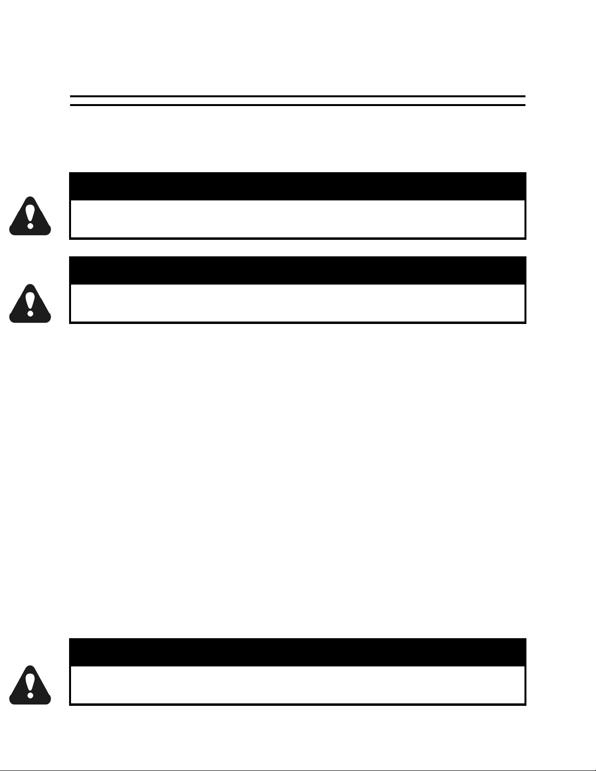
WARNING TEXT BOXES
Below are definitions of the warning text boxes:
Indicates an imminently hazardous situation which, if not avoided, will
result in death or serious injury.
Indicates a potentially hazardous situation which, if not avoided, could
result in death or serious injury.
Indicates a potentially hazardous situation which, if not avoided, could
result in minor or moderate injury.
Advises reader of information or instructions vital to the operation or
maintenance of the equipment.
DANGE
WARNING
CAUTION
NOTE
AT2T-2742-1 Rev. E
ACCU-STEAM ELECTRIC GRIDDLE OWNERS MANUAL
Page 1 / 41
Page 6
SAFETY WARNINGS (cont.)
SYMBOL ICONS
Below are definitions of symbol icons used in this manual:
ALERT – Notifies the reader of an important message/warning, usually a safety related
message.
INFORMATION – Notifies the reader of important information that may or may not be
safety-related.
EARTH GROUND
DANGEROUS VOLTAGE
CAUTION, HOT SURFACE
AT2T-2742-1 Rev. E
ACCU-STEAM ELECTRIC GRIDDLE OWNERS MANUAL
Page 2 / 41
Page 7
THEORY OF OPERATION
INTRODUCTION
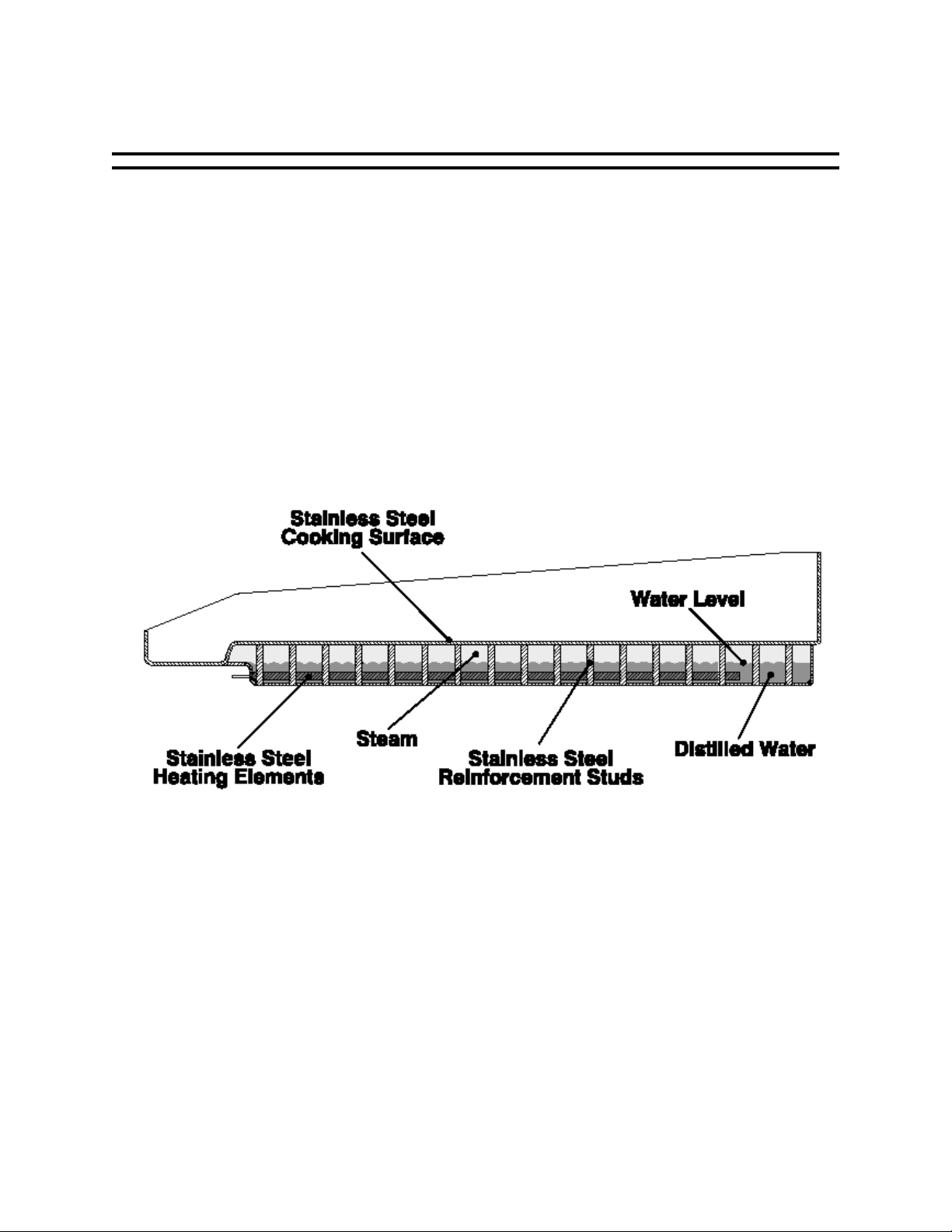
The ACCU-STEAM™ griddle is constructed and uses technology like no other griddle
in the world. The diagram below is a cross-sectional view of the griddle. The griddle
cooking surface is the top of a chamber in which we have produced a unique
environment. Welded stainless steel reinforcement studs connect the chamber top to
the chamber bottom. The perimeter joints are all robotically welded and to produce a
vessel that is airtight, which is verified using a helium mass spectrometer. The
chamber is filled half full with distilled water. The remaining air is removed and the
chamber is welded shut. At this point, the chamber becomes a hermetically sealed
vessel, never to be opened again. The griddle steam chamber requires no water
or maintenance. A thermowell for a thermocouple to sense temperature and a
thermowell for the overtemp safety shutdown system are also welded into the griddle
steam chamber.
At temperatures below 212°F (100°C), the chamber is actually in a vacuum, similar to
that of a canning jar. At temperatures above 212°F (100°C), the chamber operates
under pressure. Located between the water and the bottom of the cooking surface is
the best heat transfer medium – steam, the most effective way to transfer heat. The
thermocouple senses the temperature of the steam and reports this data to the
thermostat, which energizes the heating elements. This system maintains the griddle
cooking surface temperatures to within ± 3°F (1.7°C) over the entire cooking surface
and provides a near instant temperature recovery, even in the same spot on the
griddle, when turning food in place.
AT2T-2742-1 Rev. E
ACCU-STEAM ELECTRIC GRIDDLE OWNERS MANUAL
Page 3 / 41
Page 8
INSTALLATION
Only qualified service technicians/electricians should perform the
installation to ensure that all electrical and safety requirements are met
and that all wiring is performed in accordance with all national, state and
LOCATION AND PLACEMENT
The AccuTemp ACCU-STEAM™ electric griddle has been designed to be placed on a
commercial kitchen counter-top, an AccuTemp griddle stand or directly onto any flat,
level surface.
The operating temperature ranges from 200°- 400°F (93°- 204°C). Since these
temperatures can also be found on surfaces around the perimeter of the griddle, care
should be given not to install griddle next to or against, objects or surfaces with a low
melting or flash point.
Temperatures on and around the griddle cooking surface could cause
LEVELING
The griddle must be installed in a level condition. An out-of-level condition may
cause damage to the griddle and damage of this type is not covered by warranty. Use a
spirit level resting on the griddle surface to ensure it is level front-to-back and left-toright.
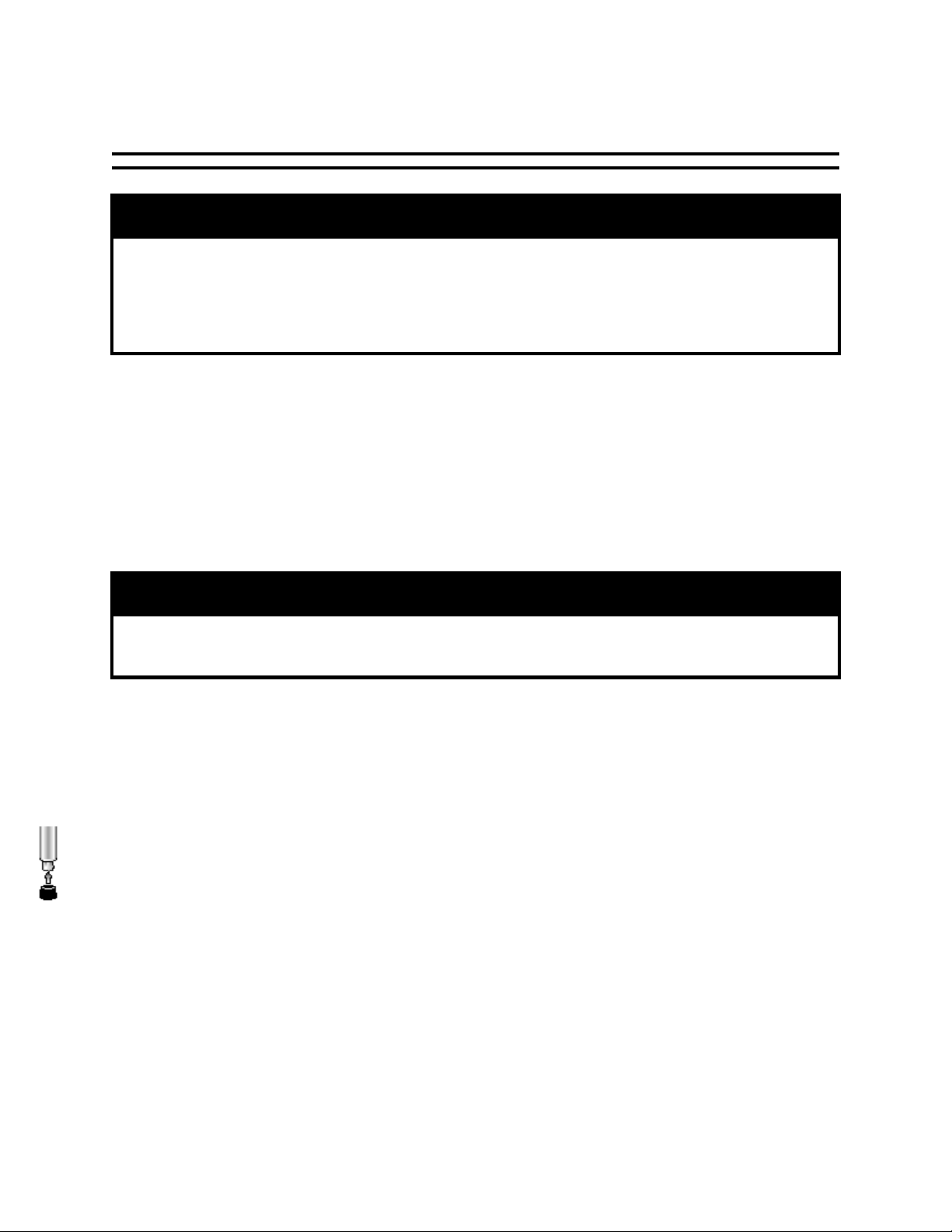
If this is a counter-top installation, be sure to install the (4) rubber foot
tips provided with your griddle onto the four foot adjusters of each of the
griddle leg as shown. This will keep the griddle from sliding on the counter-top under
normal use. Once the rubber foot tips have been installed, adjust the four foot
adjusters up or down as needed to level the griddle.
If your griddle is attached to an AccuTemp stand with casters, ensure that the floor
surface is level and place the two locking casters to the “on” position.
WARNING
local electrical codes.
CAUTION
severe burns.
AT2T-2742-1 Rev. E
ACCU-STEAM ELECTRIC GRIDDLE OWNERS MANUAL
Page 4 / 41
Page 9
INSTALLATION (cont.)
R
IN-FIELD MODIFICATIONS
This griddle has a totally unique design and is constructed unlike any other griddle
on the market today. Any modification may permanently damage the griddle.
Any in-field modification made without written authorization from
AccuTemp will void all warranties.
Any in-field modifications that bypass the built-safety features of this
product will result in death or serious injury.
ELECTRICAL SUPPLY
The ACCU-STEAM™ griddle has been designed, manufactured and tested to meet or
exceed the demanding standards of safety set forth by Underwriters Laboratories, Inc.
To ensure that this high level of safety is maintained in your installation, it is important
that you read and understand the following information before attempting to plug in
your griddle.
ELECTRICAL REQUIREMENTS
Electrical requirements are listed on the data plate located on the right side of the
unit, near the front. All standard AccuTemp griddles are supplied with a 6ft (1.83m)
cord and the appropriate UL listed plug. Please note, that the plug is rated for 250VAC.
This plug is commonly used for both 208VAC and 240VAC installations. Make sure that
the voltage at your supply receptacle is within ± 10 % of the voltage listed on the
griddle data plate. Connection to any other voltage may cause damage to components
in the griddle and damage of this type is not covered under warranty.
GROUNDING INSTRUCTIONS
Grounding provides a path for electric current to reduce the risk of shock. This
product is equipped with a power cord having a grounding conductor and a grounding
plug.
WARNING
DANGE
This appliance must be properly grounded, in accordance with all National,
AT2T-2742-1 Rev. E
WARNING
State and local electrical codes.
ACCU-STEAM ELECTRIC GRIDDLE OWNERS MANUAL
Page 5 / 41
Page 10
INSTALLATION (cont.)
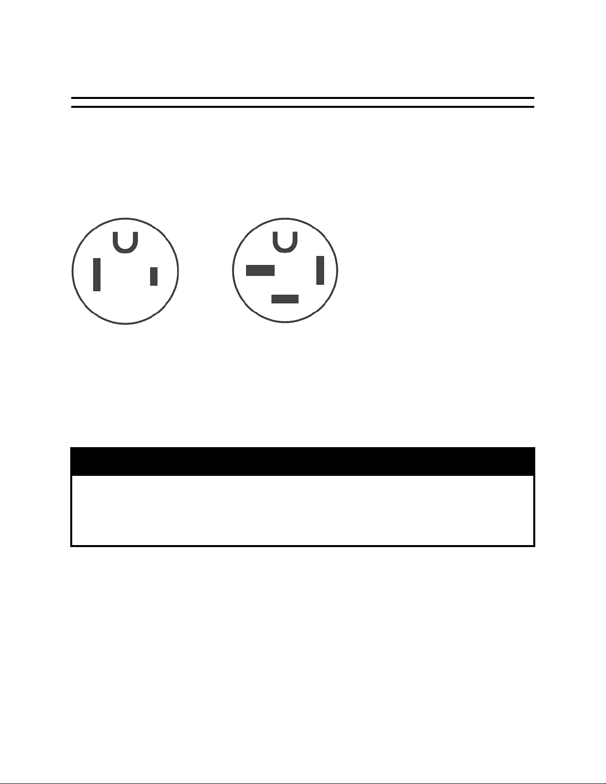
ELECTRICAL CONNECTIONS
The receptacle requirements vary between models. If you have purchased a
single-phase model, you will need a NEMA 6-50R receptacle. If you have
purchased a three-phase model, you will need a NEMA 15-50R receptacle.
These receptacles are configured as shown below.
NEMA 6-50R NEMA 15-50R
GRIDDLE LIFTING
Griddles are heavy enough to require additional manpower or powered assistance
when installing or moving the griddle.
CAUTION
This appliance is heavy. For safe handling, the installer should obtain help
as needed or employ appropriate material handling equipment to remove
the appliance from the skid and move into its final destination.
AT2T-2742-1 Rev. E
ACCU-STEAM ELECTRIC GRIDDLE OWNERS MANUAL
Page 6 / 41
Page 11
INSTALLATION (cont.)
DROP-IN GRIDDLE
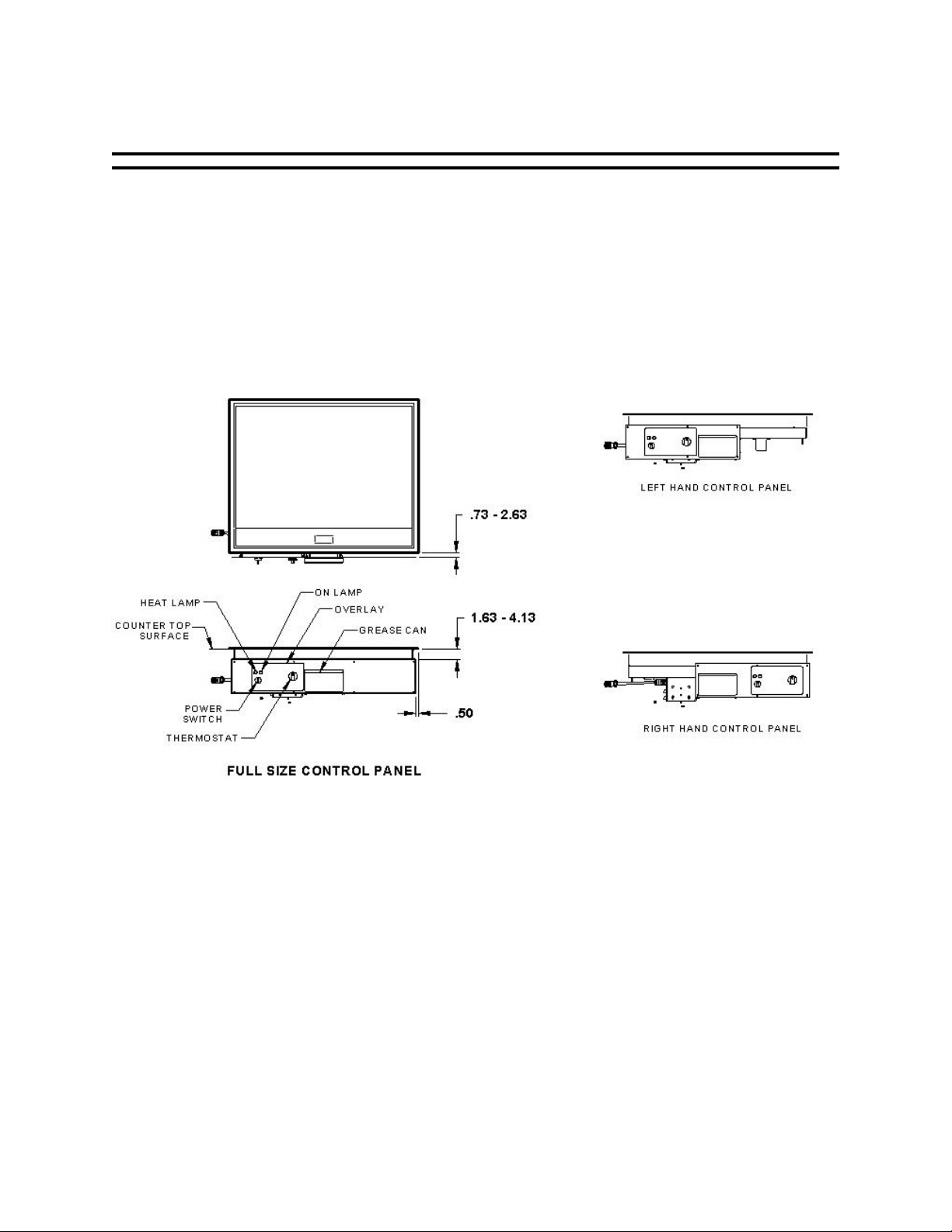
Fig. 1
Introduction
It is highly recommended that a survey of the kitchen site be conducted to
determine the requirements for the installation. Electrical supply, counter space as well
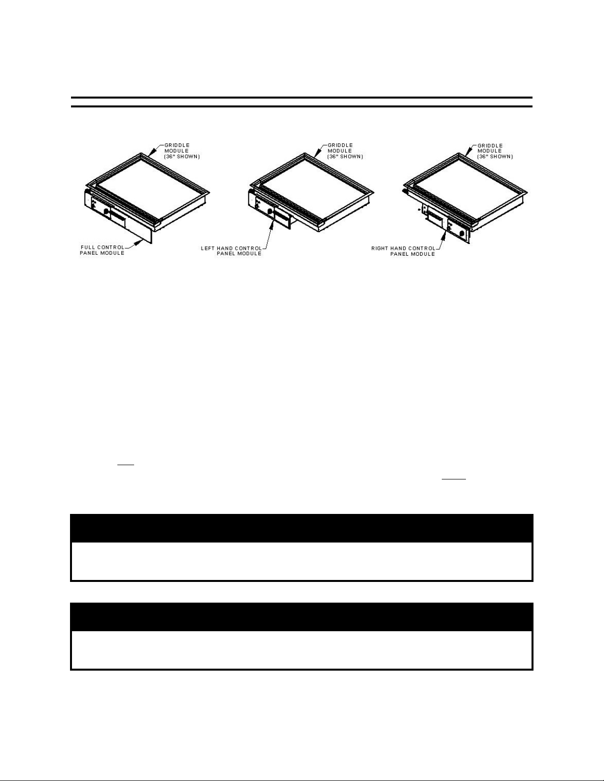
as counter arrangement are critical to the choice of Drop-In-Griddle options. The DropIn-Griddle is available in many options to accommodate size, control panel
arrangements and supply voltage. The model data label indicating the model
number, phase, voltage, current, wattage and UL information is located on
the bottom cover of the unit.
Counter designs that have an “L” arrangement such that the shortest part of the “L”
is to the
has an “L” arrangement such that the shortest part of the “L” is to the right may require
a “Left Hand Control Panel” option. See Figure 1 for views of these configurations.
left may require a “Right Hand Control Panel” option. A counter design that
WARNING
This product is to be installed in stainless steel or non-combustible
countertops only.
NOTE
Installation must allow inspection and serviceability to the underside of
the unit.
AT2T-2742-1 Rev. E
ACCU-STEAM ELECTRIC GRIDDLE OWNERS MANUAL
Page 7 / 41
Page 12

INSTALLATION (cont.)
DROP-IN GRIDDLE
GETTING STARTED
Please read and comprehend all instructions and manuals provided with each DropIn-Griddle. Read and understand all safety warnings and operator instructions for all
powered tools required to complete the installation of the Drop-In-Griddle.
Disconnect all power from house supply connection boxes at the appropriate
fuse panel and label the breakers “In service”. This is to warn others that work is
in process, preventing accidental electrocution.
TYPICAL TOOLS AND SUPPLIES REQUIREMENTS
• Putty knife
• Grease solvents
• Clean sponges or rags
• Latex gloves
• Caulking gun
• Approximately 3oz. NSF-approved aluminized silicone sealant
• Tape measure
• Carpenters square
• #2 Phillips screw driver
• Channel lock pliers
• ½ inch box/open wrench
• 3/8 inch nut driver
• 3/8 inch electric or cordless drill
• #25 drill bit
• 3/8 inch drill bit
• Saber saw with metal cutting blades
• Permanent marking pen, preferably a “Sharpie” fine point.
• 4 inch grinder. (If replacing an existing competitors griddle, it is recommend to
use a 4 inch grinder to clean off any welds, welded on brackets or framing
attached to the counter top.)
LIST OF PACKAGING REQUIREMENTS:
• (1) Owners/Installation Manual
• (1) Griddle Module
• (1) Control Panel Module
• (1) Cable Assembly
• (4) Grease Spout Extension
• (1) Grease Trough Assembly
• (1) Grease Tray Assembly
• (1) Grease Trough Hanger Bracket
• (1) Grease Trough Hanger
AT2T-2742-1 Rev. E
ACCU-STEAM ELECTRIC GRIDDLE OWNERS MANUAL
Page 8 / 41
Page 13
INSTALLATION (cont.)
DROP-IN GRIDDLE
• (8) 10-24 x 3/8 inch Self-Tapping Truss Head Screw
• (6) 10-24 x ½ inch Phillips Round Head Machine Screw
• (2) 5/16-18 X ¾ inch Carriage Head Bolt
• (2) 5/16 inch Lock Washer
• (2) 5/16-18 Hex Nut
• (8) 1/4-20 Nyloc Nut
• (4) Retainer Bracket
• (1) Thermostat Knob Guard
INSTALLATION PROCEDURE
1. Inspect the griddle packaging to ensure there are no missing components.
2. Complete the appropriate power disconnection procedures for existing
equipment or local power junction boxes.
3. Clean surfaces with grease solvents and dry off with clean rags or sponges.
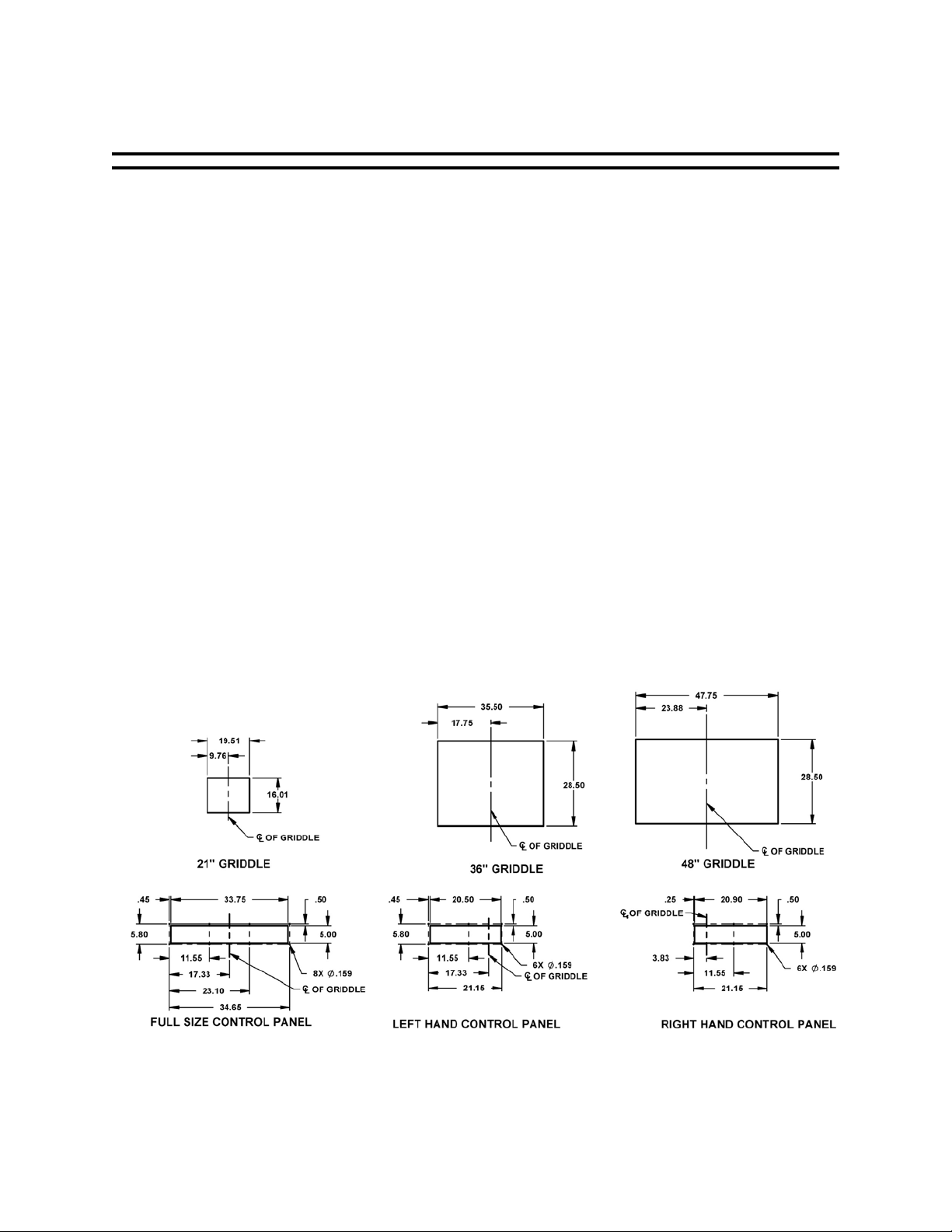
4. Determine the location and orientation for the griddle and control panel modules.
Mark the centerline on the countertop for the griddle module, using a Carpenter’s
square. See Figure 2 for the countertop and control panel layouts. Continue the
centerline to the control panel module mounting surface. Accurate centerline
alignment of the countertop and control panel modules is critical to ensure the
correct alignment of the grease trough assembly to the griddle module.
AT2T-2742-1 Rev. E
Fig. 2
ACCU-STEAM ELECTRIC GRIDDLE OWNERS MANUAL
Page 9 / 41
Page 14
INSTALLATION (cont.)
DROP-IN GRIDDLE
5. The dimensional relationship between the griddle module mounting flange and
the control panel module is shown in Figure 3. The griddle module mounting
flange overlaps the countertop cutout by 0.50 inches on all four sides. Mark the
griddle module cutout on the countertop such that the front edge of the griddle
module is 0.73 inches – 2.63 inches from the control panel module mounting
surface, as shown in Figure 3. Mark the control panel module cutout on the
control panel module mounting surface, as shown in Figure 2.
Fig. 3
6. Cut out the griddle and control panel module openings. Straighten out any dings
or bent edges in both cutouts to ensure adequate sealing between the new
griddle and the counter top surface and between the control panel and the front
surface of the counter.
7. Drill the mounting holes in the face of the counter using a #25 drill bit. Drill the
first set of holes and locate the remaining holes using the control panel as a
template.
8. Use a lifting device, if possible, to raise the griddle module above the counter
and position over cutout in countertop. Lower the griddle module carefully into
the cutout. Install the retainer clamps to the griddle module, using the ¼-20
nylock nuts (see drawing AT2A-3044, sheet 6).
AT2T-2742-1 Rev. E
ACCU-STEAM ELECTRIC GRIDDLE OWNERS MANUAL
Page 10 / 41
Page 15

INSTALLATION (cont.)
DROP-IN GRIDDLE
9. Install the control panel onto the counter face using #10-24 x 3/8 inch selftapping screws. Also, at this time, install the thermostat knob guard, if
necessary, by lining up the holes on the guard to the holes on the control panel
directly above and below the thermostat.
10. Install the grease trough hanger brackets onto the bottom side of the griddle
using (2) #10-24 X ½ inch Phillips round head machine screws and (2) 5/16-18
X ¾ inch carriage head bolts with (2) 5/16 inch lock washers and (2) 5/16-18
nuts (see drawing AT2A-3044, sheet 6). Leave the carriage bolts loose for
adjustment of the g rease trough.
11. Install the grease trough using (4) #10-24 X ½ inch Phillips round head machine
screws through the front panel opening and through the hanger bracket
assembly, installed in step 10.
12. Adjust the hanger bracket height so that the grease trough is setting level frontto-back and tighten the 5/16-18 nuts.
13. Install the appropriate size grease spout extension onto the griddle grease spout,
that ensures the bottom of the grease spout extension is flush to the inside
surface of the grease trough assembly (see drawing AT2A-3044, sheet 6).
14. Use the caulking gun to lay a 1/8” minimum diameter bead of the aluminized
silicone sealant around the griddle module mounting flange onto the counter top.
Use a gloved finger to wipe the sealant into a fillet shape.
15. Install the interconnect cable between the control panel module and the control
box, mounted on the bottom side of the griddle (see drawing AT2A-3044, sheet
6).
16. Set the on/off switch to the off position and set the temperature control knob to
the lowest setting.
17. Install the power cord into an appropriate sized electrical connection box with an
appropriate sized cord grip or cable strain relief. Complete the final
connections, testing the house supply wire first to ensure it is not live.
18. Turn on power to the griddle at the fuse panel.
19.Turn the griddle on and set the temperature control knob to a desired
setting. Wait a minimum of 20 minutes. Then use a suitable temperaturemeasuring device to check the griddle surface temperature. The surface
temperature should be within 5 – 7 °F of the temperature control knob setting.
If it is not, go to the calibration section and follow the calibration procedures.
20.This completes the drop-in griddle installation.
AT2T-2742-1 Rev. E
ACCU-STEAM ELECTRIC GRIDDLE OWNERS MANUAL
Page 11 / 41
Page 16

INSTALLATION (cont.)
DROP-IN GRIDDLE
CALIBRATION
The griddle has been pre-calibrated in the factory and should not require additional
calibration. If calibration is necessary, complete the following steps:
1. Remove the cover from the contactor box assembly to expose the
control components (see drawing AT2A-3044, sheets 4 or 5).
2. Locate the thermostat control circuit board (see drawing AT2A-2577) and identify
the two potentiometers. The “LO OFFSET” potentiometer is the only
potentiometer to be adjusted.
3. Make VERY SMALL adjustments. Observe the surface temperature, allowing a
minimum of five minutes for the griddle to stabilize before making any more
adjustments (see Figure 4).
4. When the surface temperature and the temperature control knob indicator are
within 5 – 7 °F of each other, reinstall the contactor box cover and this
calibration procedure is completed.
Figure 6
AT2T-2742-1 Rev. E
ACCU-STEAM ELECTRIC GRIDDLE OWNERS MANUAL
Page 12 / 41
Page 17

OPERATION
SEASONING
It is recommended that you clean your ACCU-STEAM™ griddle thoroughly before
turning your unit on. To clean the griddle surface, just simply wash the cooking surface
down with a solution of mild soap and water, and then rinse thoroughly with clean
water.
Once the cooking surface has been cleaned, set the thermostat to 200°F (93°C),
turn the griddle power switch to the “On” position and allow the griddle cooking surface
to heat for 10 minutes. Using a high temperature oil, such as
Shortening
Whirl
™ or equivalent, pour enough to cover the entire griddle
™,
surface. Do not use standard vegetable oil to season the griddle cooking
surface. It may cause food to stick and result in improperly cooked food. Work this
seasoning oil into the griddle surface with a regular heavy-duty scrub pad for about 5
minutes, making sure that you scrub the seasoning oil over the entire griddle-cooking
surface. After the entire griddle surface has been scrubbed with seasoning oil for 5
minutes, simply wipe or squeegee off excess oil from griddle surface. Your griddle is
now ready to use!
If you use chemicals to clean your griddle periodically or on a schedule,
you may need to repeat this process after the use of chemicals.
PREHEATING
Turn On switch to the “On” position and set the thermostat to the desired
temperature. The griddle will increase its surface temperature at an average rate of 15°
F (8°C) per minute. It takes approximately 22 minutes to raise the griddle from room
temperature to its maximum temperature of 400° F (204°C). The griddle will be
preheated when the “Heat” light starts to cycle on and off. Please use caution as
temperatures on and around the griddle cooking surface could cause severe
burns.
COOKING
Begin cooking only after the griddle has been preheated to the desired temperature.
Please note these facts:
• You can cook all the way to the edges of the griddle surface because the
temperature does not very across the entire cooking surface.
• You can turn the product to the same spot because the griddle has near
instant heat recovery.
• It will always cook the same, regardless of product load or surface coverage.
Accurate Cooking Temperatures
Because of the inaccurate surface temperatures and long recovery times common
with other griddles. It is doubtful you were cooking at the set temperature or the
temperature you wanted. Adjust the temperature on your A
CCU-STEAM™ griddle and it
Pan and Grill
AT2T-2742-1 Rev. E
ACCU-STEAM ELECTRIC GRIDDLE OWNERS MANUAL
Page 13 / 41
Page 18

OPERATION (cont.)
won’t change or vary by the location on the griddle surface. There are no hot or cold
zones.
Heat Lamp
It is normal for the heat light to cycle on and off. This light indicates when the
heaters are energized. You will soon notice how little they are energized to maintain
perfect surface temperatures on your griddle.
Grease Pan
Use caution when emptying the grease pan. The contents in this pan could cause
severe burns. The pan should be checked periodically and emptied as necessary to
prevent an overflow or dangerous condition.
CAUTION
The grease can contents could cause severe burns. Slowly remove the
grease can from the griddle to avoid spilling the contents.
DAILY CLEANING
Cleaning during the work shift can be performed with a sharp scraper. When heavy
cleaning at the end of a shift or periodically as needed, the following is recommended:
• Turn the griddle off and allow it to cool to between 220°F and 240°F
(104°F and 116°C). Use water, ice and/or griddle cleaner as needed. For
example, the 3M Scotch-Brite™ Quick Clean Griddle System provides the
Scotch-Brite™ polishing pads, quick clean liquid, pad holder and squeegee.
Clean-up is very easy using these tools with the quick clean liquid, water, ice
or combinations of these liquids.
• If a griddle with grease on the cooking surface is cleaned at a high
temperature using water or ice, the grease may splatter and cause
skin burns. Be very cautious!
• Do not use a griddle stone or brick to clean the griddle.
• Do not use a water-jet to clean the griddle.
NOTE
Never leave a chlorine sanitizer in contact with the stainless steel longer
than 10 minutes. Longer contact can cause corrosion.
AT2T-2742-1 Rev. E
ACCU-STEAM ELECTRIC GRIDDLE OWNERS MANUAL
Page 14 / 41
Page 19

SERVICE AND TROUBLESHOOTING
R
An AccuTemp Products, Inc. Technical Service Technician is available
Monday thru Sunday, 7:00am to 7:00pm EST.
+1-260-469-3040 or 1-800-480-0415
NO USER-SERVICEABLE PARTS
There are no user-serviceable parts. AccuTemp-authorized service personnel should
complete any servicing. Service performed by unauthorized personnel will void the
warranty.
There are no user-serviceable parts. To prevent electrical shock do not
open access panel covers.
Only qualified service technicians/electricians should perform the
installation to ensure that all electrical and safety requirements are met
and that all wiring is performed in accordance with all national, state and
local electrical codes.
Any in-field modification made without written authorization from
AccuTemp will void the warranty.
Any in-field modifications that bypass the built-safety features of this
product will result in death or serious injury.
NOTE
WARNING
WARNING
WARNING
DANGE
AT2T-2742-1 Rev. E
ACCU-STEAM ELECTRIC GRIDDLE OWNERS MANUAL
Page 15 / 41
Page 20

SERVICE AND TROUBLESHOOTING (cont.)
This appliance must be properly grounded, in accordance with all National,
State and local electrical codes.
Service must only be performed by AccuTemp Products, Inc.- authorized
service personnel. Service performed by unauthorized personnel will void
Use of any replacement parts other than those supplied by AccuTemp
Products, Inc. can cause injury to the operator or damage the appliance
and voids all warranties.
GENERAL SERVICE INFORMATION
Most conventional griddles require regularly scheduled service (i.e. recalibrating the
thermostat). The ACCU-STEAM™ griddle has no such requirements, due to its design.
BASIC TROUBLESHOOTING
Griddle will not turn on
• Make sure the griddle is plugged in and the “On/Off” switch is in the On
position.
• Check the facility circuit breaker (or fuse) supplying the unit.
• Call AccuTemp Products, Inc Technical Service at +1-260-469-3040 or toll
free at 1-800-480-0415.
Heat light will not come on
• Make sure the griddle is not hotter than the temperature you have it set for.
If you have turned down the temperature of the griddle, the heat light will
not come on again until the cooking surface drops below the temperature you
have set.
• See if the heat light is coming on intermittently. While operating in a normal
condition, the heat light cycles on and off periodically when at temperature.
WARNING
NOTE
the warranty.
WARNING
AT2T-2742-1 Rev. E
ACCU-STEAM ELECTRIC GRIDDLE OWNERS MANUAL
Page 16 / 41
Page 21

SERVICE AND TROUBLESHOOTING (cont.)
• Call AccuTemp Products, Inc Technical Service at +1-260-469-3040 or toll
free at 1-800-480-0415.
Uneven or inaccurate surface temperatures
• Verify the surface temperature with an accurate surface probe thermometer.
Use of an infrared thermometer will not give an accurate reading of the
griddle surface temperatures.
• Call AccuTemp Products, Inc Technical Service at +1-260-469-3040 or toll
free at 1-800-480-0415.
Unit will not turn off
• This system, which is extremely rare, indicates a serious control malfunction.
• Turn off the griddle’s electrical supply at the source.
• Call AccuTemp Products, Inc Technical Service at +1-260-469-3040 or toll
free at 1-800-480-0415.
An AccuTemp Products, Inc. Technical Service Technician is available
Monday thru Sunday, 7:00am to 7:00pm EST.
+1-260-469-3040 or 1-800-480-0415
NOTE
AT2T-2742-1 Rev. E
ACCU-STEAM ELECTRIC GRIDDLE OWNERS MANUAL
Page 17 / 41
Page 22

SERVICE PARTS CROSS-REFERENCE:
NAVY GRIDDLE MODEL NUMBERS
COUNTERTOP MODELS
Service
Model
EGF4403B3602-00 AT2A-3044 19 and 21 AT2T-2947 34
EGF4403B2405-T3 AT2A-3044 19 and 21 AT2T-2947 34
EGF4403B3605-T3 AT2A-3044 19 and 21 AT2T-2947 34
EGF4403B4805-T3 AT2A-3044 19 and 21 AT2T-2947 34
[Models manufactured after 5/31/05]
EGF4403B3602-00 AT2A-3044 19 – 21 AT2T-2947 33 31
EGF4403B2405-T3 AT2A-3044 19 – 21 AT2T-2947 33 31
EGF4403B3605-T3 AT2A-3044 19 – 21 AT2T-2947 33 31
EGF4403B4805-T3 AT2A-3044 19 – 21 AT2T-2947 33 31
DROP-IN MODELS
Model
EGD4403B3606-00 AT2A-3044
EGD4403B4806-00 AT2A-3044
EGD4403B3606-00 AT2A-3044
EGD4403B4806-00 AT2A-3044
Parts
Drawing
Number
[Models manufactured prior to 6/1/05]
Service
Parts
Drawing
Number
[Models manufactured prior to 6/1/05]
[Models manufactured after 5/31/05]
Service
Parts –
Owners
Manual
Page(s)
Service
Parts –
Owners
Manual
Page(s)
21, 22, 24
and 25
21, 22, 24
and 25
21, 23, 24
and 26
21, 23, 24
and 26
Schematic
Drawing
Number
Schematic
Drawing
Number
AT2T-2713 39
AT2T-2713 39
AT2T-2713 36
AT2T-2713 36
Schematic – Owners
Manual Page(s)
Prior to
9/23/05
Schematic – Owners
Manual Page(s)
After
9/22/05
AT2T-2742-1 Rev. E
ACCU-STEAM ELECTRIC GRIDDLE OWNERS MANUAL
Page 18 / 41
Page 23

C
Rev.Drawing No.:Size:
Sheet 1 of 6
8415 N. Clinton Park
Fort Wayne, IN 46825
AccuTemp Products, Inc.
AT2A-3044
EDR: 085
SERVICE PARTS LIST
NAVY ELECTRIC GRIDDLE
Title:
Date
1-24-05DPS
ATP 1-24-05
Name
Unless otherwise specified,
Dimensions: Inches
GLS 1-24-05
Project Eng
Drawn
Checked
Bends: 90
Tolerances:
Material:
Angular 1°
2 Place Decimal .02
3 Place Decimal .005
T.I.R .005
D
Scale: 1:8
GD&T Per ANSI Y14.5M
N/A
Finish:
Do Not Scale Drawing
Comments:
N/A
√125 Micro Inches
C
1 AT0E-1587-2 34 3 POLE CONTACTOR
B
4 AT0F-2755-41040 33 #10-24UNC X 1/2 PHIL RD HD MACH SCREW
1 AR AT2M-3183-3 32 BAR, 48" GRIDDLE GRAB
B
1 AR AT2M-3183-2 32 BAR, 36" GRIDDLE GRAB
1 AR AT2M-3183-1 32 BAR, 24" GRIDDLE GRAB
B
B
2 AT2H-3184-1 31 END BRKTS, GRIDDLE GRAB BAR
2 AT0F-2875-71080 30 3/8-16UNC X 1 HEX HD MACH SCREW
2 AT0F-2778-71001 29 3/8-16 UNC-2B 316 SS HEX NUT
B
B
B
4 AT0F-2755-41050 21 #10-24UNC X 5/8 PHIL RD HD MACH SCREW
4 AT2A-3032-3 20 3.00" LEG ASSEMBLY
1 AT0F-2632-40001 19.7 #10-24 NUT, ACORN
1 AT0F-1922-40000 19.6 #10 WASHER LOCK, SS HELICAL SPRING
1 AT0F-1052-43010 19.5 WASHER, #10 TYPE B CUSTOM
1 AT0F-3012-1 19.4 SPACER, ROUND
1 AT2M-3008-1 19.3 LEVER, GREASE PAN
1 AT2M-2551-2 19.2 GREASE TRAY FACE PLATE
1 AT0F-1046-41040 19.1 #10-24 x 1/2 PHLP TRUSS HEAD
1 AT2A-2552-2 19 ASSY, BAFFLED LOCKING GREASE TRAY
1 AT2A-2529-2 18 GREASE TROUGH ASSY
1 AT0A-2788-14 17 POWER CABLE ASSY
1 AT0E-1049-5 16 1" STRAIN RELIEF
1 AT0A-2876-2 15 MDR WITH TERMINALS
1 AT2E-1220 14 RELAY, 240V MERCURY DISPLACEMENT
1 AT2E-1035 13 RELAY, 208V MERCURY DISPLACEMENT
1 AT0E-3025-2 12 INSULATOR STRIP, 4 POSITION DOUBLE ROW
1 AT0E-1134-4 11 4 POSITION TERMINAL BLOCK
1 AT2M-1559-1 10 COVER
1 AT2A-2916-1 9 HIGH LIMIT OVERTEMP ASSEMBLY
1 AT0E-2662-3 8 TRANSFORMER
1 AT2M-1740 28 SKIRT, LEFT SIDE (24" DEEP GRIDDLE)
1 AT2M-1739 27 SKIRT, RIGHT SIDE (24" DEEP GRIDDLE)
8 AT0F-2875-51062 26 1/4-20 X 3/4 HEX HD MACH SCREW
2 AT0F-2691-41002 25 #10-24 NYLOC NUT
4 AT0F-2777-31030 24 #8 TYPE AB X 3/8 TRUSS HEAD SCREW
2 AT0F-2755-41070 23 #10-24UNC X 7/8 PHIL RD HD MACH SCREW
16 AT0F-1046-31030 22 #8-32 x 3/8 PHLP TRUSS HEAD
17
B
B
C
B
2
22
B
3
6
34
B
1 AT0E-1587-1 7 3 POLE CONTACTOR
1 AR AT2M-1738 6 SKIRT, FRONT (48" GRIDDLE)
B
1 AR AT2M-2187 6 SKIRT, FRONT (36" GRIDDLE)
B
1 AR AT2M-2186 6 SKIRT, FRONT (24" GRIDDLE)
B
1 AT2G-1026 5 GASKET, CONTROL PANEL, EG
1 AT0E-2659-1 4.7 MOUNTING LATCH
2 AT0E-2657-1 4.6 CONTACT BLOCK
1 AT0E-1800-5 4.5 INDICATOR LAMP RED NEON 250V
1 AT0E-1800-4 4.4 INDICATOR LAMP GRN NEON 250V
1 AT2E-1034 4.3 THERMOSTAT
1 AT0H-1455-2 4.2 KNOB FOR D SHAFT
1 AT0E-1755-1 4.1 ON/OFF SWITCH
1 AT2A-3189-1 4 ASSY, ELECTRIC GRIDDLE CONTROL PANEL
B
1 AT2G-1022 3 GASKET, ACCESS POWER TERMINAL, EG
1 AT2M-1021 2 PANEL, ACCESS POWER TERMINAL, EG
1 AT2A-2185 1 WELD ASSY, CHAMBER
QTY PART NUMBER ITEM DESCRIPTION
B
33
16
27
7
26
20
C
5
8
SEE SHEET #3
"HIGH LIMIT OVERTEMP ASSEMBLY
DETAIL VIEW"
9
25
ITEM NO 15 MDR USED ON ALL ELECTRIC COUNTERTOP GRIDDLES
1
NOTES:
WITH MFR DATE OF 1-26-05 THRU PRESENT
ITEM NO 14 MDR USED ON 440/240V GRIDDLES
2
ITEM NO 13 MDR USED ON 208V GRIDDLES
3
WITH MFR DATE PRIOR TO 1-26-05
WITH MFR DATE PRIOR TO 1-26-05
4. FOR USE IN 440/480 PRIMARY VOLTAGE UNITS ONLY
ITEM NO 7 CONTACTOR USED ON ALL ELECTRIC COUNTERTOP GRIDDLES
5
WITH MFR DATE OF 1-1-05 THRU PRESENT
ITEM NO 34 CONTACTOR USED ON ALL ELECTRIC COUNTERTOP GRIDDLES
6
WITH MFR DATE PRIOR TO 1-1-05
10
24
C
C
12
3
2
11
13
14
B
1
1
B
30
28
B
B
32
6
23
4.6
B
33
15
4.3
5
31
B
29
31
19
19.1
19.219.3
18
21
4.7
4.4
4.1
4.2
22
4
12/30/05 DPS/ATP
12/2/05 DPS/ATP
4.5
19.4
19.5
19.6
19.7
AT2T-2741-1 Rev. E ACCU-STEAM ELECTRIC GRIDDLE OWNERS MANUAL Page 19 / 41
REVISIONS
ADDED: (SHT 1) ITM 34, FLAG NOTE NEXT TO
ITM 7, NOTES 5 & 6
RMV’D: (SHT 1) ITM 29 AT2H-2357, CHG’D:
DWG TITLE WAS ELECTRIC GRIDDLE
SERVICE PARTS LIST, (SHT 1) ITM 1 AT2A-
2185 WAS AT2A-2185-10, ITM 4 AT2A-3189-1
WAS AT2A-CP2, ITM 6 AT2M-2187 QTY 1 AR
WAS 1, ITM 17 AT0A-2788-14 WAS AT0A-2788-
9, ITM 21 QTY 4 WAS 6, ITM 23 AT0F-2755-
41070 WAS AT0F-2755-41060, ITM 25 QTY 2
WAS 4, ITM 30 AT0F-2875-71080 WAS AT0F-
2061-41060, (SHT 4) ITM 5 AT0F-2755-41040
WAS AT0F-1017-41002, (SHT 5) ITM 4 AT0F-
2755-41040 WAS AT0F-1017-41002, (SHT 6) ITM
1 AT2A-2520 WAS AT2A-2520-2, ITM 3 AT2A-
2552-3 WAS AT2A-2552-1, ITM 4 AT2A-2529-3
WAS AT2A-2529-1, ADDED: (SHT 1) ITM 6
AT2M-2186, ITM 6 AT2M-1738, ITM 29 AT2A-
2778-71001, ITM 31, ITM 32, ITM 33, (SHT 6) ITM
20
253 C
243 B
234 A CHG'D: SHT #5 WAS SHT #4, ADDED SHT #4 08-09-05 ALB
ECN REV DESCRIPTION DATE APPR
Page 24

C
Rev.Drawing No.:Size:
Sheet 2 of 6
8415 N. Clinton Park
Fort Wayne, IN 46825
AccuTemp Products, Inc.
AT2A-3044
EDR: 085
SERVICE PARTS LIST
NAVY ELECTRIC GRIDDLE
Title:
Date
07-14-05DPS
Name
A BREMER 07-13-05
Drawn
Checked
Unless otherwise specified,
Dimensions: Inches
Bends: 90
Tolerances:
Angular 1°
N/A
G SEITZ 07-15-05
Proj Eng
Material:
2 Place Decimal .02
3 Place Decimal .005
T.I.R .005
D
Scale: 1:8
N/A
Finish:
Do Not Scale Drawing
Comments:
√125 Micro Inches
GD&T Per ANSI Y14.5M
4 AT0F-1017-41002 17 #10-24UNC HEX SERRATED NUT
4 AT0F-2666-40000 16 #10 LOCK WASHER INTERNAL TOOTH
4 AT0F-2755-41040 15 #10-24UNC X 1/2 PHIL RD HD MACH SCREW
4 AT0F-2666-30000 14 #8 LOCK WASHER INTERNAL TOOTH
4 AT0F-2755-31040 13 #8-32UNC X 1/2 PHIL RD HD MACH SCREW
1 AT0A-3112-1 12 ASSY, HARNESS
1 AT0A-3112-2 11 ASSY, HARNESS
1 AT0A-3112-3 10 ASSY, HARNESS
1 AT0A-3112-4 9 ASSY, HARNESS
1 AT0A-3111-2 8 CONTROL INPUT HARNESS
1 AT0A-3111-1 7 CONTROL INPUT HARNESS
2 AT0E-2059-3 6 RELAY, SOLID STATE
2 AT0E-2996-1 5 PAD, SSR HEAT SINK
2 AT0E-2206-3 4 HEAT SINK, 3.43" LONG
1 AT0H-2576-1 3 GROMMET, 7/8" NYLON
1 AT2M-3104-1 2 COVER, RELAY ENCLOSURE
1 AT2M-3103-1 1 CHASSIS, RELAY ENCLOSURE
QTY PART NO. ITEM DESCRIPTION
1
3
17
5
4
ELECTRIC GRIDDLE WITH SSR
(36" WIDE MODEL BOTTOM VIEW SHOWN)
6
14
13
12
11
10
9
7
8
2
16
15
AT2T-2741-1 Rev. E ACCU-STEAM ELECTRIC GRIDDLE OWNERS MANUAL Page 20 / 41
Page 25

C
Rev.Drawing No.:Size:
Sheet 3 of 6
8415 N. Clinton Park
Fort Wayne, IN 46825
AccuTemp Products, Inc.
AT2A-3044
EDR: 085
SERVICE PARTS LIST
#6-32UNC X 1 1/4 PHIL RD HD MACH SCREW
11
NAVY ELECTRIC GRIDDLE
Title:
Date
1-24-05DPS
ATP 1-24-05
Name
WASHER 1/4 TYPE B PLAIN
#6-32 NYLOC NUT
9
10
Unless otherwise specified,
Dimensions: Inches
GLS 1-24-05
Project Eng
Drawn
Checked
Bends: 90
Tolerances:
Material:
Angular 1°
2 Place Decimal .02
3 Place Decimal .005
T.I.R .005
D
Scale: 1:8
N/A
√125 Micro Inches
GD&T Per ANSI Y14.5M
N/A
Finish:
Do Not Scale Drawing
Comments:
AT0F-2755-21102
2
2 AT0F-1017-41002 12 #10-24UNC HEX SERRATED NUT
2
AT0F-1052-51002
2
AT0F-2691-21002
1 AT0E-1759-1 8 MICROSWITCH COVER
1 AT2E-1639-1 7 MICROSWITCH
1 AT2H-1640-1 6 EXTENSION SPRING
1 AT2M-1558-1 5 BRACKET, SWITCH
1 AT2H-1365-1 4 COMPRESSION SPRING
1 AT2F-1367-1 3 WASHER, TYPE A
1 AT2M-2860-1 2 SOLDER WASHER
1 AT2M-2861-1 1 WIRE ROD
QTY PART NO. ITEM DESCRIPTION
11
8
12
7
6
5
4
DETAIL VIEW
HIGH LIMIT OVERTEMP ASSEMBLY
2
1
3
10
9
AT2T-2741-1 Rev. E ACCU-STEAM ELECTRIC GRIDDLE OWNERS MANUAL Page 21 / 41
Page 26

C
Rev.Drawing No.:Size:
Sheet 4 of 6
8415 N. Clinton Park
Fort Wayne, IN 46825
AccuTemp Products, Inc.
AT2A-3044
EDR: 085
SERVICE PARTS LIST
12
NAVY ELECTRIC GRIDDLE
Title:
Date
1-24-05DPS
ATP 1-24-05
Name
Unless otherwise specified,
Dimensions: Inches
GLS 1-24-05
Project Eng
Drawn
Checked
Bends: 90
Tolerances:
Material:
Angular 1°
2 Place Decimal .02
3 Place Decimal .005
T.I.R .005
D
Scale: 1:8
N/A
√125 Micro Inches
GD&T Per ANSI Y14.5M
N/A
Finish:
Do Not Scale Drawing
Comments:
10
9
8
7
13
11
DROP-IN ELECTRIC GRIDDLE CONTROL PANEL
(FULL WIDTH CONFIGURATION SHOWN)
1 AT0E-2705-2 12 REMOTE POT & HARNESS
1 AT0H-1455-1 11 KNOB WITH SET SCREW
1 AT0E-2657-1 10 CONTACT BLOCK
1 AT0E-1800-2 9 INDICATOR LAMP RED INCANDESCENT 28V
1 AT0E-1800-1 8 INDICATOR LAMP GRN INCANDESCENT 28V
1 AT2M-2907-1 13 THERMOSTAT GUARD BRKT
1 AT0E-1755-1 7 ON/OFF SWITCH
QTY PART NO ITEM DESCRIPTION
1 AT2M-1559-2 6 COVER
2 AT0F-2755-41040 5 #10-24UNC X 1/2 PHIL RD HD MACH SCREW
B
8 AT0F-2777-31030 4 #8 TYPE AB X 3/8 TRUSS HEAD SCREW
1 AT2M-2561-2 3 BOX COVER, CONTACTOR
1 AT2A-2577-2 2 CONTROL BOX ASSEMBLY
1 AT2A-2520 1 GRIDDLE ASSEMBLY
QTY PART NO ITEM DESCRIPTION
B
(36" WIDE MODEL BOTTOM VIEW SHOWN)
DROP-IN ELECTRIC GRIDDLE WITH MDR
5
3
4
2
4
6
1
SEE SHEET 3 "HIGH LIMIT OVERTEMP ASSEMBLY DETAIL VIEW"
AT2T-2741-1 Rev. E ACCU-STEAM ELECTRIC GRIDDLE OWNERS MANUAL Page 22 / 41
Page 27

C
Rev.Drawing No.:Size:
Sheet 5 of 6
8415 N. Clinton Park
Fort Wayne, IN 46825
AccuTemp Products, Inc.
AT2A-3044
EDR: 085
SERVICE PARTS LIST
11
10
NAVY ELECTRIC GRIDDLE
Title:
Date
02-03-04GLS
ALB 02-03-04
Name
Unless otherwise specified,
Dimensions: Inches
GLS 02-03-04
Project Eng
Drawn
Checked
Bends: 90
Tolerances:
Material:
Angular 1°
2 Place Decimal .02
3 Place Decimal .005
T.I.R .005
D
Scale: 1:12
GD&T Per ANSI Y14.5M
N/A
Finish:
Do Not Scale Drawing
Comments:
N/A
√125 Micro Inches
12
13
DROP-IN ELECTRIC GRIDDLE CONTROL PANEL
AT2M-1559-2 6 COVER
1 AT2M-2907-1 13 THERMOSTAT GUARD BRKT
1 AT0H-1455-1 12 KNOB WITH SET SCREW
1 AT0E-2705-2 11 REMOTE POT & HARNESS
1 AT0E-2657-1 10 CONTACT BLOCK
1 AT0E-1800-1 9 INDICATOR LAMP GRN INCANDESCENT 28V
1 AT0E-1800-2 8 INDICATOR LAMP RED INCANDESCENT 28V
1 AT0E-1755-1 7 ON/OFF SWITCH
QTY PART NO. ITEM DESCRIPTION
1
1 AT2M-2646-1 5 COVER CONTROL BOX
4 AT0F-2755-41040 4 #10-24UNC X 1/2 PHIL RD HD MACH SCREW
8 AT0F-2777-31030 3 #8 TYPE AB X 3/8 TRUSS HEAD SCREW
1 AT2A-2577-3 2 CONTROL BOX ASSEMBLY
1 AT2A-2520 1 GRIDDLE ASSEMBLY
QTY PART NO. ITEM DESCRIPTION
B
(FULL WIDTH CONFIGURATION SHOWN)
8
9
7
DROP-IN ELECTRIC GRIDDLE WITH SSR
(36" WIDE MODEL BOTTOM VIEW SHOWN)
B
4
1
3
5
2
3
6
SEE SHEET 3 "HIGH LIMIT OVERTEMP ASSEMBLY DETAIL VIEW"
AT2T-2741-1 Rev. E ACCU-STEAM ELECTRIC GRIDDLE OWNERS MANUAL Page 23 / 41
Page 28

C
Rev.Drawing No.:Size:
Sheet 6 of 6
8415 N. Clinton Park
Fort Wayne, IN 46825
AccuTemp Products, Inc.
AT2A-3044
EDR: 085
SERVICE PARTS LIST
NAVY ELECTRIC GRIDDLE
Title:
Date
09-02-05DPS
ALB 09-02-05
Name
Unless otherwise specified,
Dimensions: Inches
DPS 09-02-05
Project Eng
Drawn
Checked
Bends: 90
Tolerances:
Material:
Angular 1°
2 Place Decimal .02
3 Place Decimal .005
T.I.R .005
D
Scale: 1:8
GD&T Per ANSI Y14.5M
N/A
Finish:
Do Not Scale Drawing
Comments:
N/A
√125 Micro Inches
12
1 AT2M-2907-1 20 THERMOSTAT GUARD BRKT
B
8 AT0F-2777-41040 19 #10 TYPE AB X 1/2 TRUSS HEAD SCREW
6 AT0F-2755-41040 18 #10-24UNC X 1/2 PHIL RD HD MACH SCREW
2 AT0F-2778-61000 17 5/16-18 UNC-2B SS HEX NUT
2 AT0F-1922-60000 16 5/16" WASHER LOCK, HELICAL SPRING
2 AT0F-1921-61060 15 BOLT, 5/16-18 UNC 2A X 3/4" CARRIAGE
1 AT2T-2742-1 14 ELECTRIC GRIDDLE OWNERS MANUAL
8 AT0F-2691-51002 13 1/4-20 NYLOC NUT
4 AT2M-2535-1 12 RETAINER BRACKET
1 AT2A-2764-1 11 CABLE ASSEMBLY
1 AT2A-2592-5 10 5" GREASE SPOUT EXTENSION
1 AT2A-2592-3 9 3" GREASE SPOUT EXTENSION
1 AT2A-2592-1 8 1" GREASE SPOUT EXTENSION
1 AT2A-2592-2 7 2" GREASE SPOUT EXTENSION
1 AT2M-2554-1 6 GREASE TROUGH HANGER
1 AT2M-2553-1 5 GREASE TROUGH HNGR BRKT
1 AT2A-2529-3 4 GREASE TROUGH ASSY
B
1 AT2A-2552-3 3 ASSY, LONG BAFFLED LOCKING GREASE TRAY
B
1 AT2A-2526-1 2 CONTROL PANEL ASSY - FULL
1 AT2A-2520 1 GRIDDLE ASSEMBLY
QTY PART NO. ITEM DESCRIPTION
B
13
18
16
17
5
15
6
14
7
B
4
18
19
B
20
8
9
10
1
B
3
2
11
OF ITEM #2
TO BACK SIDE
AT2T-2741-1 Rev. E ACCU-STEAM ELECTRIC GRIDDLE OWNERS MANUAL Page 24 / 41
Page 29

F
Rev.Drawing No.:Size:
Sheet 1 of 2
8415 N. Clinton Park
Fort Wayne, IN 46825
AccuTemp Products, Inc.
4
CONTROL
BOX ASSEMBLY
AT2A-2577
EDR: 038B
D
Title:
Date
2/3/2004GLS
ALB 8/1/2003
Name
GLS 2/3/2004
Project Eng
Drawn
Checked
N/A
Material:
Scale: 1:2
N/A
Finish:
NOTES: UNLESS OTHERWISE SPECIFIED
Do Not Scale Drawing
Unless otherwise specified,
Dimensions: Inches
Bends: 90
Tolerances:
Angular 1°
FOR AT2A-2577-2 WIRING SCHEMATIC SEE DRAWING AT2T-2767-2 OR1.
DRAWING AT2T-2713 SHEETS 4, 5, OR 6.
1 AT2A-2760-2 26 CABLE ASSEMBLY
2 AT0F-2668-1 27 #10-24 HEX NUTSERT
1 AT0E-3025-2 25 INSULATOR STRIP, 4 POSITION DOUBLE ROW
2 AT0F-2755-41050 24 #10-24UNC X 5/8 PHIL RD HD MACH SCREW
2 AT0A-2615-5 23 WIRE HARNESS
1 AT0A-2615-3 22 WIRE HARNESS
1 AT0A-2615-2 21 WIRE HARNESS
4 AT0F-1017-41001 20 #10-24UNC HEX SERRATED NUT
1 AT0E-1134-4 19 4 POSITION TERMINAL BLOCK
4 AT0F-2755-41040 18 #10-24UNC X 1/2 PHIL RD HD MACH SCREW
2 AT0E-2731-2 17 FUSE 1¼ AMP 250V
1 AT0A-2876-1 16 MDR WITH TERMINALS
1 AT0E-2662-5 15 TRANSFORMER
1 AT0A-2617-1 14 5.0" HIGH TEMP WIRE ASSEMBLY WHITE
1 AT0A-2761-1 13 CABLE GROUND WIRE ASSY
1 AT0A-2736-8 12 MOV- TERMINALS ASSEMBLY
1 AT0A-2736-7 11 MOV- TERMINALS ASSEMBLY
4 AT0F-2777-31030 10 #8 TYPE AB X 3/8 TRUSS HEAD SCREW
2 AT0F-2755-41020 9 #10-24UNC X 1/4 PHIL RD HD MACH SCREW
4 AT0F-2755-21050 8 #6-32UNC X 5/8 PHIL RD HD MACH SCR
6 AT0F-2755-21020 7 #6-32UNC X 1/4 PHIL RD HD MACH SCR
1 AT0E-2708-1 6 3AG OMNI-BLOK FUSE BLOCK 2 POS
1 AT0E-2705-1 5 ZYTRON THERMOSTAT
2 AT0H-2887-1 3 CABLE TIE MOUNT
1 AT0E-1587-4 2 3 POLE CONTACTOR
PART NO. ITEM DESCRIPTION
1 AT2M-2560-2 1 BOX, CONTROL
√125 Micro Inches
2 Place Decimal .02
3 Place Decimal .005
GD&T Per ANSI Y14.5M
T.I.R .005
Comments:
QTY
AT2A-2577-2
F
E
E
E
C
C
C
E
E
E
F
8
5
D
15
D
23
7
D
D
D
22
23
21
E
3
6
17
7
2
9
E
25
AT2A-2577-2
E
19
24
F
27
12
18
14
16
C
11
20
GLS / ALB
GLS / AP
GLS / ALB
GLS
GLS / ALB
GLS / ALB
1
EF
26
13
D
10
AT2T-2741-1 Rev. E ACCU-STEAM ELECTRIC GRIDDLE OWNERS MANUAL Page 25 / 41
08-12-05
RMV’D: AT2A-2577-1/SHT 1, CHG’D: SHT 1/AT2A-2577-2 WAS SHT
AT2M-2668-1
2/AT2A-2577-2, (AT2A-2577-2) NOTE 1 WAS FOR AT2A-2577-2
WIRING SCHEMATIC SEE DRAWING AT2T-2767-2, ITM 1 AT2M-2560-
2 WAS AT2A-3028-2, ADDED: AT2A-2577-3, (AT2A-2577-2) ITM 27
216 F
12-10-04
AT0F-2047-1 ITMNO 4, AT2M 2560-2 ITMNO 1, CHG’D: (SHT 2) ITMNO
RMV’D: (SHT 1) AT0F-2047-1 ITMNO 4, AT2M 2560-1 ITMNO 1, (SHT2)
20 AT0E-1134-4 WAS AT0E-1134-1, ITMNO 8 QTY 4 WAS 6, ADDED:
(SHT 1) AT2A-3028-1 ITMNO 1, (SHT 2) AT0F-2755-41050 ITMNO 25,
183 E
06-03-04
AT0E-3025-2 ITMNO 26, AT2A-3028-2 ITMNO 1
CHG'D: (SHT 1) ITEM 20 AT0E-2662-5 WAS AT0A-2779-1; ITEM 19
MOVE PICTORIALLY: ADDED ITEMS 25, 26 & 27: CHG'D (SHT 2) ITEM
16 AT0E-2662-5 WAS AT0A-2779-1; ITEM 14 MOVE PICTORIALLY:
112 D
05-04-04
04-26-04
02-12-04
REVISIONS
ADDED ITEMS 22, 23 & 24
AT0E-1134-3; AT0F-2755-21020 QTY 4 WAS 2; AT0F-2755-21050 GP-1
CHG'D #6-32UNC X 5/8 WAS #6-32UNC X 1/2; AT0E-1134-1 WAS
QTY 4 WAS 6 & GP-2 QTY 6 WAS 8; ITEM 18: AT0E-2731-2 WAS AT0E-
095 C
AT1E-2576-2 PER ECN 081, ADDED SHEET 2 (AT2A-2577-2)
2731-3; ITEM#3 AT0H-2887-1 WAS AT0H-2576-2; ON AT2A-2577-2
ROTATED ITEM #12 108º
CHG'D: ITEM #17 WAS AT0E-2736-2, ITEM # 2 (AT0H-2576-2) WAS
CHG AT0A-2617 WAS AT0E-2617; AF0H-2666 WAS AT1F-2666
088 B
065 A
ECN REV DESCRIPTION DATE APPR
Page 30

F
Rev.Drawing No.:Size:
Sheet 2 of 2
8415 N. Clinton Park
Fort Wayne, IN 46825
AccuTemp Products, Inc.
CONTROL
BOX ASSEMBLY
AT2A-2577
EDR: 038B
D
Title:
Date
2/3/2004GLS
ALB 8/1/2003
Name
GLS 2/3/2004
Project Eng
Drawn
Checked
N/A
Material:
Scale: 1:8
N/A
Finish:
NOTES: UNLESS OTHERWISE SPECIFIED
Do Not Scale Drawing
Unless otherwise specified,
Dimensions: Inches
Bends: 90
Tolerances:
Angular 1°
2 Place Decimal .02
3 Place Decimal .005
T.I.R .005
FOR AT2A-2577-3 WIRING SCHEMATIC SEE DRAWING AT2T-2767-1 OR1.
DRAWING AT2T-2713 SHEETS 1, 2, OR 3.
Comments:
GD&T Per ANSI Y14.5M
√125 Micro Inches
PART NO. ITEM DESCRIPTION
QTY AT2A-2577-3
1 AT0A-2617-33 32 8.0" HIGH TEMP WIRE ASSEMBLY BLACK
1 AT0A-2617-32 31 7.0" HIGH TEMP WIRE ASSEMBLY BLACK
1 AT0A-2617-31 30 6.0" HIGH TEMP WIRE ASSEMBLY RED
1 AT0A-2617-3 29 5.0" HIGH TEMP WIRE ASSEMBLY RED
1 AT2A-2760-4 28 CABLE ASSEMBLY
1 AT0A-2617-1 27 5.0" HIGH TEMP WIRE ASSEMBLY WHITE
2 AT0A-2615-5 26 WIRE HARNESS
1 AT0A-2615-3 25 WIRE HARNESS
1 AT0A-2615-2 24 WIRE HARNESS
1 AT0A-2761-1 23 CABLE GROUND WIRE ASSY
4 AT0F-2666-30000 22 #8 LOCK WASHER INTERNAL TOOTH
4 AT0F-2668-1 21 #10-24 HEX NUTSERT
5 AT0F-1017-41001 20 #10-24UNC HEX SERRATED NUT
7 AT0F-2755-41050 19 #10-24UNC X 5/8 PHIL RD HD MACH SCREW
2 AT0F-2755-41020 18 #10-24UNC X 1/4 PHIL RD HD MACH SCREW
4 AT0F-2755-31030 17 #8-32UNC X 3/8 PHIL RD HD MACH SCR
4 AT0F-2777-31030 16 #8 TYPE AB X 3/8 TRUSS HEAD SCREW
4 AT0F-2755-21050 15 #6-32UNC X 5/8 PHIL RD HD MACH SCR
6 AT0F-2755-21020 14 #6-32UNC X 1/4 PHIL RD HD MACH SCR
2 AT0E-2996-1 13 PAD, SSR HEAT SINK
2 AT0E-2059-3 12 RELAY, SOLID STATE
2 AT0E-2206-3 11 HEAT SINK, 3.43" LONG
2 AT0H-2887-1 10 CABLE TIE MOUNT
1 AT0A-2736-8 9 MOV- TERMINALS ASSEMBLY
1 AT0E-2662-5 8 TRANSFORMER
2 AT0E-2731-2 7 FUSE 1¼ AMP 250V
1 AT0E-2708-1 6 3AG OMNI-BLOK FUSE BLOCK 2 POS
1 AT0E-3025-2 5 INSULATOR STRIP, 4 POSITION DOUBLE ROW
1 AT0E-1134-4 4 4 POSITION TERMINAL BLOCK
1 AT0E-2705-1 3 ZYTRON THERMOSTAT
1 AT0E-1587-4 2 3 POLE CONTACTOR
1 AT2M-2560-3 1 BOX, CONTROL
12
22
17
30
29
23
28
19
20
27
18
19
4
9
5
2
7
6
15
11
13
32
31
3
26
24
25
20
F
8
AT2A-2577-3
14
19
16
10
1
21
AT2T-2741-1 Rev. E ACCU-STEAM ELECTRIC GRIDDLE OWNERS MANUAL Page 26 / 41
Page 31

G
R E D , # 3 W A S B L K , # 4 W A S B L K , # 5 W A S
Rev.Drawing No.:
Sheet 1 of 8
8415 N. Clinton Park
Fort Wayne, IN 46825
AccuTemp Products, Inc.
SPECIFICATIONS
22" & 24" MOD ELS
36" & 48" MOD ELS
240V unit, 18.0 OHM, 3.2KW ea.
208V unit, 13 .52 OHM, 3.2KW ea.
HEATER ELEMENT ELECTRICAL
208V unit, 9.11 OHM, 4.75KW ea.
240V unit, 12 .13 OHM, 4.75KW ea.
Title:
8/17/04
8/17/04
Date
08/17/04
K TYPE
YEL RED
o
t
R2
R1 R3
6
N
L3
RED
L3
MDR
RED
L3
MASTER
CONTACTOR
3
1
542
L2
L1
BLK
WHT
L1
BLK
WHT
L2
L1
BLK
WHT
VIO
RLY 2
WHT
ORN
RED
RLY 1
WHT
ORN
WHT VIO YEL REDORN
ZR1
PWR NA C OM OUTPUT + -
1 2 3 4 5 6 7
N.O.
N.C.
SW2
O.T. SW
RED
RED
1 P1 2
1 J1 2
RED
ORN
K TYPE CONTROLLER CAL OFFSET ADJ
VIO
LT2
HEAT
WHT
LT1
PWR
ORN
Name
G. SEITZ
G. SEITZ
D. STANLEY
Drawn
Project Eng
Checked
Bends: 90
Tolerances:
Angular 1°
Unless otherwise specified,
Dimensions: Inches
0 1 / 2 8 /0 5 G . S E I T Z
R E V IS I O N S
W H T , # 6 W A S W H T
W IR E C O N N E C T IO N S A L L S H E E T S ,
A L L S H E E T S ) # 1 W A S R E D ,# 2 W A S
R M V ' D : # 1 D E S I G N A T IO N F O R H E A T E R
C H G 'D : (H E A T E R W IR E D E S I G N A T I O N -
1 8 3 A A D D E D : 4 P O S IT IO N T E R M I N A L S T R IP 1 2 / 1 3 / 0 4 G . S E IT Z
1 9 7 B
E C N R E V D E S C R IP T IO N D A T E A P P R
AT2T-2947-1
AT2T-2947
EDR: 061
C
SCHEMATIC, ELEC GRIDDLE
Size:
Scale: 16:1
Material:
Finish:
Do Not Scale Drawing
2 Place Decimal .02
3 Place Decimal .005
T.I.R .005
125 Micro Inches
GD&T Per ANSI Y14.5M
Comments:
0 2 / 0 9 /0 5 G . S E I T Z
0 5 / 1 8 /0 5 G . S E I T Z
0 7 / 2 6 /0 5 G . S E I T Z
1 1 / 1 0 /0 5 G . S E I T Z
M D R
2 9 4 7 -7 & A T 2 T - 2 9 4 7 -8
( A T 2 T - 2 9 4 7 -4 T H R U - 6 )
C H G 'D : (S H T S 1 -3 ) M D R L E G
C H G ’D : T IT L E S C H E M A T I C , E L E C
E L E C T R I C A L S P E C S D A T A F I E L D ,
C H G 'D : (S H T S 1 ,2 & 3 ) R O U T I N G O F
T O H E A T L IG H T , A D D E D : S H T S 4 , 5 & 6
A D D E D : ( A L L S H E E T S ) M O V A C R O S S
L T 1 C O N N E C T I O N F R O M C O N T A C T O R
G R ID D L E W A S S C H E M A T I C , G R I D D L E ,
D E S IG N A T IO N L 3 W A S L 2 , M O V E D P W R
R L Y -1 T O T E R M I N A L 4 O N T H E R M O S T A T
C O M M O N W H T C O N D U C T O R F R O M M D R
C H G 'D : (S H T S 1 ,2 , 4 , 5 ) H E A T E R E L E M E N T
A D D E D : S H E E T 7 & 8 S C H E M A T I C S A T 2 T -
2 0 2 C
2 2 5 D
2 4 3 F
2 3 4 E
1 2 /2 9 / 0 5 G . S E ITZ
ORN
SW1
ON/OFF
BLK
RED
BLK
WHT
GRN
AT2T-2742-1 Rev. E ACCU-STEAM ELECTRIC GRIDDLE OWNERS MANUAL Page 27 / 41
208V/240V DELTA MDR HEATER CONFIGURATION
R E V IS IO N S
4 4 0 /4 8 0 V D E LT A M D R H E A T E R
S S R H E A TE R C O N F IG U R A T IO N
(S H T 7 ) 4 4 0 / 4 8 0 V D E L T A S S R H E A T E R
C H G 'D : C O N F IG U R A T IO N D E S C R IP TI O N
C O N F IG U R A TI O N W A S 4 4 0 / 4 80 V D E L TA
C O N F IG U R A TI O N W A S 4 4 0 / 4 80 V D E L TA
M D R H E A TE R C O N F I G U R A TI O N , (S H T 8 )
2 5 2 G
E C N R E V D E S C R IP TIO N D A T E A P P R
Page 32

G
Rev.Drawing No.:
Sheet 2 of 8
8415 N. Clinton Park
Fort Wayne, IN 46825
24" MODELS
SPECIFICATIONS
HEATER ELEMENT ELECTRICAL
36" & 48" MODELS
380V unit, 18.0 OHM, 2.680KW ea.
415V unit, 18.0 OHM, 3.197KW ea.
440V unit, 18.0 OHM, 3.594KW ea.
480V unit, 18.0 OHM, 4.277KW ea.
380V unit, 9.11 OHM, 5.300KW ea.
415V unit, 12.13 OHM, 4.745KW ea.
440V unit, 12.13 OHM, 5.334KW ea.
480V unit, 12.13 OHM, 6.346KW ea.
K TYPE
YEL RED
o
t
R2
ORN
AccuTemp Products, Inc.
AT2T-2947
EDR: 061
SCHEMATIC, ELEC GRIDDLE
Title:
Date
8/17/04
8/17/04
08/17/04
Name
G. SEITZ
G. SEITZ
D. STANLEY
Drawn
Project Eng
Checked
C
Size:
Scale: 16:1
Material:
Finish:
R1 R3
WHT VIO YEL REDORN
2
6
4
N
L3
5
RED
L3
MDR
RED
L3
MASTER
CONTACTOR
3
1
L2
L1
BLK
WHTWHT
L1
BLK
L2
L1
BLK
WHT
VIO
RLY 2
WHT
ORN
RED
RLY 1
WHT
ZR1
PWR NA COM OUTPUT + -
1 2 3 4 5 6 7
N.O.
N.C.
SW2
O.T. SW
RED
RED
1 P1 2
1 J1 2
RED
ORN
K TYPE CONTROLLER CAL OFFSET ADJ
VIO
LT2
HEAT
LT1
PWR
ORN WHT
AT2T-2947-2
ORN
SW1
ON/OFF
BLK
Bends: 90
Tolerances:
Angular 1°
2 Place Decimal .02
Unless otherwise specified,
Dimensions: Inches
380V - 480V WYE MDR HEATER CONFIGURATION
Do Not Scale Drawing
Comments:
3 Place Decimal .005
T.I.R .005
125 Micro Inches
GD&T Per ANSI Y14.5M
240V
220V/
COM
480V
440V
TO COMMON (WHT) AT RLY1
OMIT TRANSFORMER
CONNECT SUPPLY NEUTRAL
CONNECT L1 (BLK) TO SW1
L3 RED
L1 BLK
L2 WHT
GRN
*NEUTRAL
5 WIRE SYSTEM (4 WIRE W/GND)
AT2T-2742-1 Rev. E ACCU-STEAM ELECTRIC GRIDDLE OWNERS MANUAL Page 28 / 41
Page 33

G
Rev.Drawing No.:
Sheet 3 of 8
8415 N. Clinton Park
Fort Wayne, IN 46825
AccuTemp Products, Inc.
AT2T-2947
3.2KW ea.
1Ø MODELS
ELECTRICAL
SPECIFICATIONS
HEATER ELEMENT
240V unit, 18.0 OHM,
K TYPE
YEL RED
o
t
ORN
SCHEMATIC, ELEC GRIDDLE
Title:
Date
8/17/04
8/17/04
08/17/04
Name
G. SEITZ
G. SEITZ
D. STANLEY
Drawn
Material:
Project Eng
Checked
EDR: 061
C
Size:
Scale: 16:1
Finish:
R1 R3R2
2
143
N
L2
L3
6
RED
L2
MDR
L3
MASTER
CONTACTOR
L1
5
BLK
L1
BLK
RED
L2
L1
BLK
WHT
VIO
RLY 2
WHT
ORN
RED
RLY 1
WHT
WHT VIO YEL REDORN
ZR1
PWR NA COM OUTPUT + -
1 2 3 4 5 6 7
N.O.
N.C.
SW2
O.T. SW
RED
RED
1 P1 2
1 J1 2
RED
ORN
K TYPE CO NTROLLER CAL OFFS ET ADJ
VIO
LT2
HEAT
WHT
LT1
PWR
ORN
ORN
SW1
ON/OFF
BLK
AT2T-2947-3
Bends: 90
Tolerances:
Angular 1°
2 Place Decimal .02
Unless otherwise specified,
Dimensions: Inches
240V SINGLE PHASE MDR HEATER CONFIGURATION
Do Not Scale Drawing
Comments:
3 Place Decimal .005
T.I.R .005
125 Micro Inches
GD&T Per ANSI Y14.5M
BLK
WHT
GRN
AT2T-2742-1 Rev. E ACCU-STEAM ELECTRIC GRIDDLE OWNERS MANUAL Page 29 / 41
Page 34

G
Rev.Drawing No.:
Sheet 4 of 8
8415 N. Clinton Park
Fort Wayne, IN 46825
AccuTemp Products, Inc.
AT2T-2947
SPECIFICATIONS
22" & 24" MODELS
36" & 48" MODELS
240V unit, 18.0 OHM, 3.2KW ea.
208V unit, 13.52 OHM, 3.2KW ea.
HEATER ELEMENT ELECTRICAL
208V unit, 9.11 OHM, 4.75KW ea.
240V unit, 12.13 OHM, 4.75KW ea.
6RED
N
L2
L3
R2
R1 R3
3
1
542
L1
BLK
WHT
SSR 2
K TYPE
o
t
VIO
WHT
ORN
WHT VIO YEL RED
ZR1
PWR NA COM OUTPUT + -
1 2 3 4 5 6 7
ORN
K TYPE CONTROLLER CAL OFFSET ADJ
SCHEMATIC, ELEC GRIDDLE
Title:
Date
8/17/04
8/17/04
08/17/04
Name
G. SEITZ
G. SEITZ
D. STANLEY
Drawn
Material:
Project Eng
Checked
Bends: 90
Tolerances:
Angular 1°
2 Place Decimal .02
Unless otherwise specified,
Dimensions: Inches
3 Place Decimal .005
EDR: 061
C
Size:
Scale: 16:1
Finish:
Do Not Scale Drawing
T.I.R .005
125 Micro Inches
GD&T Per ANSI Y14.5M
Comments:
VIO
SSR 1
WHT
RED
L3
MASTER
CONTACTOR
BLK
WHT
ORN
L2
L1
BLK
WHT
RED
RLY 1
WHT
N.O.
N.C.
SW2
O.T. SW
RED
1 P1 2
1 J1 2
RED
VIO
LT2
HEAT
LT1
PWR
ORN WHT
AT2T-2947-4
RED
ORN
ORN
SW1
ON/OFF
BLK
208V/240V DELTA SSR HEATER CONFIGURATION
RED
BLK
WHT
GRN
AT2T-2742-1 Rev. E ACCU-STEAM ELECTRIC GRIDDLE OWNERS MANUAL Page 30 / 41
Page 35

G
Rev.Drawing No.:
Sheet 5 of 8
8415 N. Clinton Park
Fort Wayne, IN 46825
AccuTemp Products, Inc.
24" MODELS
SPECIFICATIONS
HEATER ELEMENT ELECTRICAL
36" & 48" MODELS
380V unit, 18.0 OHM, 2.68 0KW ea.
415V unit, 18.0 OHM, 3.19 7KW ea.
440V unit, 18.0 OHM, 3.59 4KW ea.
480V unit, 18.0 OHM, 4.27 7KW ea.
380V unit, 9.11 OHM, 5.30 0KW ea.
415V unit, 12.13 OHM, 4.745KW ea.
440V unit, 12.13 OHM, 5.334KW ea.
480V unit, 12.13 OHM, 6.346KW ea.
R2
R1 R3
2
6
4
N
L3
5
RED
3
1
L2
L1
BLK
WHT
K TYPE
o
t
ORN
Title:
Date
8/17/04
8/17/04
08/17/04
Name
G. SEITZ
G. SEITZ
D. STANLEY
Drawn
Project Eng
Checked
AT2T-2947
EDR: 061
C
SCHEMATIC, ELEC GRIDDLE
Size:
Scale: 16:1
Material:
Finish:
VIO
Bends: 90
Tolerances:
Angular 1°
2 Place Decimal .02
Unless otherwise specified,
Dimensions: Inches
SSR 2
WHT
VIO
SSR 1
WHT
RED
L3
MASTER
CONTACTOR
BLK
WHT
ORN
L2
L1
BLK
WHT
RED
RLY 1
WHT
WHT VIO YEL REDORN
ZR1
PWR NA COM OUTPUT + -
1 2 3 4 5 6 7
N.O.
N.C.
SW2
O.T. SW
RED
RED
1 P1 2
1 J1 2
RED
ORN
K TYPE CONTROLLER CAL OFFSET ADJ
VIO
LT2
HEAT
WHT
LT1
PWR
ORN
AT2T-2947-5
380V - 480V WYE SSR HEATER CONFIGURATION
ORN
SW1
ON/OFF
BLK
3 Place Decimal .005
Do Not Scale Drawing
T.I.R .005
125 Micro Inches
GD&T Per ANSI Y14.5M
Comments:
240V
220V/
COM
480V
440V
TO COMMON (WHT) AT RLY1
OMIT TRANSFORMER
CONNECT SUPPLY NEUTRAL
CONNECT L1 (BLK) TO SW1
L3 RED
L1 BLK
L2 WHT
GRN
*NEUTRAL
5 WIRE SYSTEM (4 WIRE W/GND)
AT2T-2742-1 Rev. E ACCU-STEAM ELECTRIC GRIDDLE OWNERS MANUAL Page 31 / 41
Page 36

G
Rev.Drawing No.:
Sheet 6 of 8
8415 N. Clinton Park
Fort Wayne, IN 46825
AccuTemp Products, Inc.
AT2T-2947
EDR: 061
C
SCHEMATIC, ELEC GRIDDLE
Title:
Size:
3.2KW ea.
1Ø MODELS
ELECTRICAL
SPECIFICATIONS
HEATER ELEMENT
240V unit, 18.0 OHM,
R1 R3R2
2
143
Date
8/17/04
8/17/04
08/17/04
Name
G. SEITZ
G. SEITZ
D. STANLEY
Scale: 16:1
N
L2
L3
6
RED
L3
MASTER
CONTACTOR
L1
5
BLK
VIO
SSR 1
WHT
BLK
RED
ORN
L2
L1
BLK
WHT
RED
RLY 1
WHT
K TYPE
o
t
ORN
WHT VIO YEL R EDORN
ZR1
PWR NA COM OUTPUT + -
1 2 3 4 5 6 7
N.O.
N.C.
SW2
O.T. SW
RED
RED
1 P1 2
1 J1 2
RED
ORN
K TYPE CONTROLLER CAL OFFSET ADJ
VIO
LT2
HEAT
WHT
LT1
PWR
ORN
ORN
SW1
ON/OFF
BLK
Drawn
Material:
Finish:
Project Eng
Checked
Bends: 90
Tolerances:
Angular 1°
2 Place Decimal .02
Unless otherwise specified,
Dimensions: Inches
3 Place Decimal .005
Do Not Scale Drawing
T.I.R .005
125 Micro Inches
GD&T Per ANSI Y14.5M
Comments:
AT2T-2947-6
240V SINGLE PHASE SSR HEATER CONFIGURATION
BLK
WHT
GRN
AT2T-2742-1 Rev. E ACCU-STEAM ELECTRIC GRIDDLE OWNERS MANUAL Page 32 / 41
Page 37

G
Rev.Drawing No.:
Sheet 7 of 8
8415 N. Clinton Park
Fort Wayne, IN 46825
AccuTemp Products, Inc.
22" & 24" MODELS
HEATER ELEMENT ELECTRICAL
440/480V unit, 60.60 OHM , 3.2/3.81KW ea.
440/480 V unit, 40.76 OH M, 4.75/5.65KW ea.
654
N
L2
L3
RED
R2
R1 R3
3
1
2
L1
BLK
WHT
SSR 1 SSR 2
K TYPE
o
t
ORN
VIO
WHT VIO YEL REDO RN
WHT
VIO
WHT
ZR1
K TYPE CO NTROLLER CAL OFFSET ADJ
PWR N A COM OUTPUT + -
1 2 3 4 5 6 7
VIO
LT2
HEAT
WHT
SCHEMATIC, ELEC GRIDDLE
Title:
Date
8/17/04
8/17/04
08/17/04
Name
G. SEITZ
G. SEITZ
D. STANLEY
Drawn
Material:
Project Eng
Checked
Bends: 90
Tolerances:
Angular 1°
2 Place Decimal .02
Unless otherwise specified,
Dimensions: Inches
3 Place Decimal .005
EDR: 061
C
Size:
Scale: 16:1
Finish:
Do Not Scale Drawing
T.I.R .005
125 Micro Inches
GD&T Per ANSI Y14.5M
Comments:
SPECIFICATIONS
AT2T-2947
36" & 48" MODELS
LT1
PWR
ORN
RED
L3
MASTER
CONTACTOR
BLK
WHT
ORN
L2
L1
BLK
WHT
RED
RLY 1
WHT
240V
220V/
COM
440V
480V/
N.O.
N.C.
SW2
O.T. SW
RED
RED
1 P1 2
1 J1 2
RED
ORN
ORN
SW1
ON/OFF
BLK
G
AT2T-2947-7
440/480V DELTA SSR HEATER CONFIGURATION
L3 RED
L1 BLK
L2 WHT
GRN
AT2T-2742-1 Rev. E ACCU-STEAM ELECTRIC GRIDDLE OWNERS MANUAL Page 33 / 41
Page 38

G
Rev.Drawing No.:
Sheet 8 of 8
8415 N. Clinton Park
Fort Wayne, IN 46825
AccuTemp Products, Inc.
AT2T-2947
SPECIFICATIONS
22" & 24" MODELS
36" & 48" MODELS
SCHEMATIC, ELEC GRIDDLE
HEATER ELEMENT ELECTRICAL
440/480V unit, 60.6 0 OHM, 3.2/3.81KW ea.
440/480V unit, 40.7 6 OHM, 4.75/5.65KW ea.
K TYPE
YEL RED
o
t
ORN
R2
R1 R3
WHT VIO YEL REDORN
654
N
L3
3
1
2
L2
L1
ZR1
PWR NA COM OUTPUT + -
1 2 3 4 5 6 7
K TYPE CONTROLLER CAL OFFSET ADJ
Title:
Date
8/17/04
8/17/04
08/17/04
Name
G. SEITZ
G. SEITZ
D. STANLEY
Drawn
Material:
Project Eng
Checked
Bends: 90
Tolerances:
Angular 1°
2 Place Decimal .02
Unless otherwise specified,
Dimensions: Inches
3 Place Decimal .005
EDR: 061
C
Size:
Scale: 16:1
Finish:
Do Not Scale Drawing
T.I.R .005
125 Micro Inches
GD&T Per ANSI Y14.5M
Comments:
RED
L3
MDR
RED
L3
MASTER
CONTACTOR
BLK
WHTWHT
L1
BLK
L2
L1
BLK
WHT
VIO
RLY 2
WHT
N.O.
N.C.
ORN
RED
RLY 1
WHT
240V
220V/
COM
440V
480V/
SW2
RED
1 P1 2
1 J1 2
RED
O.T. SW
VIO
LT2
HEAT
LT1
PWR
ORN WHT
AT2T-2947-8
RED
ORN
ORN
SW1
ON/OFF
BLK
G
440/480V DELTA MDR HEATER CONFIGURATION
L3 RED
L1 BLK
L2 WHT
GRN
AT2T-2742-1 Rev. E ACCU-STEAM ELECTRIC GRIDDLE OWNERS MANUAL Page 34 / 41
Page 39

H
R E D , # 3 W A S B L K , # 4 W A S B L K , # 5 W A S
D E S IG N A T I O N L 3 W A S L 2 , ( S H T 6 ) M O V E D
Rev.Drawing No.:
Sheet 1 of 6
8415 N. Clinton Park
ea.
24" MODELS
SPECIFICATIONS
36" & 48" MODELS
240V unit, 12.13 OHM, 4.75KW
240V unit, 18.0 OHM, 3.2KW ea.
208V unit, 13.52 OHM, 3.2KW ea.
HEATER ELEMENT ELECTRICAL
208V unit, 9.11 OHM, 4.75KW ea.
CONTROL
THERMOSTAT
Fort Wayne, IN 46825
Accutemp Products, Inc.
AT2T-2713
24 VAC CONTROL
GRIDDLE SCHEMATIC
EDR: 038B
LT2
HEAT
3 2 1
P4
J4
J TYPE
WHT RE D
ORN WHT REDRED
o
t
R2
R1 R3
AT0E-2705-1
ALTERNATE CONTROL PANEL WIRING
WHT
4
1
2
6
N
L3
RED
ZR2
RED
AT0E-2736-5
L
3
L2
WHT
WHT
L2L
WHT
3
5
1 2 3 C OM N.O. 4 5
L1
BLK
WHT
SSR 1 SSR 2
ZR1
BLK
RED
1
AT2E-1587-4
BLK
ZR4
RLY 1
AT0E-2736-8
WHT
F1
PWR NC COM OUTPUT OUTPUT + -
N.O.
N.C.
AT2A-2916-2
SW2
O.T. SW
RED
RED
1 P4 2
1 J4 2
BLK
BLK
AT0A-2758-1
1 P3 2
1 J3 2
BLK
BLK
BLK
WHT
F2
3AG .5A
AT0E-2731-1
BLK
P5
WHT
1 2 3
J TYPE CONTROLLER CAL OFFSET ADJ
RED
ENCLOSURE
CONTACTOR
AT2A-2764-1
AT2A-2760-1
BLK
WHT
RED
WHT
RED ORN
BLK
GRNBLU
BLK
WHT/
P2
J2
1 2 3 4 5 6 7
ORN
RED
1 2 3 4 5 6 7
BLK WHT
AT0A-2761-1
3 2 1
LT1
PWR
BLK
J1
RED
-LATCHING START CONFIGURATION-
1 2 3 4 5 6 7
BLK
GRN
AT2A-2763-1
3 2 1
3 2 1
AT2A-2762-1
BLK
J1
P1
1 2 3 4 5 6 7
1 2 3 4 5 6 7
ORN
WHT
RED
2
N.C.
P4
J4
WHT
RED
WHT
RED
1
N.O.
CR
COM
ORN
GRN
START
RUN
OFF
RED
THERMOSTAT
WHT
ON/OFF
RED
BLK
PANEL
CONTROL
BLK
SW1
NC
BLK
CONTROL
LT2
HEAT
LT1
PWR
AT0E-1800-1 AT0E-1800-2
SW1
AT2E-1755
AT2T-2713-1
PANEL
CONTROL
208/240V DELTA SSR HEATER CONFIGURATION
Title:
Date
2/04/04
2/04/04
10/15/03
Name
G. SEITZ
G. SEITZ
G. SEITZ
Drawn
Project Eng
Checked
Bends: 90
Tolerances:
Unless otherwise specified,
Dimensions: Inches
Angular 1°
1 / 9 / 2 0 0 4 G L S
3 / 9 / 2 0 0 4 G L S
R E V IS IO N S
R E L E A S E D 2 / 4 / 2 0 0 3 G L S
4 4 0 /4 8 0 V W Y E H E A T E R C O N F IG
C O N N E C T IO N O N S H E E T S 1 , 2 , 3
C H G 'D : N A M E W A S A T 2 E - 2 7 1 3 , A D D E D :
C H G 'D : P O L A R I T Y F O R T H E R M O C O U P L E
A
0 7 7 B
E C N R E V D E S C R I P T IO N D A T E A P P R
8/1 2/2005 GLS
REV ISIONS
C
Scale: 1:1
Size:
AVERY #6573
Material:
Finish:
Do Not Scale Drawing
GD&T Per ANSI Y14.5M
125 Micro Inches
2 Place Decimal .02
3 Place Decimal .005
T.I.R .005
Comments:
4 / 2 3 / 2 0 0 4 G L S
A T O E - 2 7 3 6 -2 , A D D E D : S H E E T S 4 , 5 , 6
C H G 'D : (S H E E T S 1 , 2 ,3 ) Z R 6 & Z R 7 W A S
C H G 'D : (S H T S 4 - 6 ) T E R M IN A L S T R IP W A S
0 8 8 C
2 / 9 / 2 0 0 5 G L S
1 2 / 2 / 2 0 0 4 G L S
1 / 2 8 / 2 0 0 5 G L S
W IR IN G
3 P O S . , (S H T 5 & 6 ) R E - R O U T E D H E A T E R
1 8 3 D
P O S IT IO N
W H T , # 6 W A S W H T
C H G 'D : (S H T S 4 - 6 ) M D R L E G
W IR E C O L O R "R E D " TO C O R R E C T
W IR E C O N N E C T IO N S A L L S H E E T S ,
A L L S H E E T S ) # 1 W A S R E D , # 2 W A S
R M V 'D : # 1 D E S IG N A T IO N F O R H E A T E R
C H G 'D : (H E A T E R W IR E D E S I G N A T I O N -
1 9 7 E
2 0 2 F
24V
480V
440V
240V
208V
AT0E-2662-5
FINAL SELECTION OF
PRIMARY VOLTAGE TO BE
MADE IN FINAL ASSEMBLY
RED
BLK
WHT
GRN
COM
AT2T-2742-1 Rev. E ACCU-STEAM ELECTRIC GRIDDLE OWNERS MANUAL Page 35 / 41
SY STEM FOR SOLID STATE RELA YS
CHG 'D: ( SHEE TS 1-3) RECO NFIGURE D
234 H
ECN RE V DES CRIPTION DATE AP PR
Page 40

H
DESCRIPTION
DATE
APPR
DESCRIPTION
DATE
APPR
Rev.Drawing No.:
Sheet 2 of 6
8415 N. Clinton Park
Fort Wayne, IN 46825
24" MODELS
SPECIFICATIONS
HEATER ELEMENT ELECTRICAL
2
516
N
4
36" & 48" MODELS
CONTROL
480V unit, 18.0 OHM, 4.277KW ea.
440V unit, 18.0 OHM, 3.594KW ea.
L3
RED
480V unit, 12.13 OHM, 6.346KW ea.
440V unit, 12.13 OHM, 5.334KW ea.
3 2 1
P4
J4
J TYPE
WHT R ED
ORN WHT REDRED
o
t
R2
R1 R3
AT0E-2705-1
ALTERNATE CONTROL PANEL WIRING
WHT
3
1 2 3 COM N.O. 4 5
L2
L1
WHT
BLK
PWR NC COM OUTPUT OUTPUT + -
BLK
P5
WHT
1 2 3
J TYPE CONTROLLER CAL OFFSET ADJ
RED
3 2 1
BLK
J1
RED
-LATCHING START CONFIGURATION-
1 2 3 4 5 6 7
BLK
GRN
ORN
WHT
RED
1
2
N.O.
N.C.
CR
COM
THERMOSTAT
LT2
HEAT
LT1
PWR
PANEL
CONTROL
WHT
RED
BLK
START
RUN
SW1
OFF
RED
NC
BLK
AccuTemp Products, Inc.
AT2T-2713
24VAC CONTROL
GRIDDLE SCHEMATIC
Title:
Date
2/04/04
2/04/04
01/09/04
Name
G. SEITZ
G. SEITZ
G. SEITZ
Drawn
Material:
Project Eng
Checked
Bends: 90
Tolerances:
Unless otherwise specified,
Dimensions: Inches
Angular 1°
2 Place Decimal .02
3 Place Decimal .005
EDR: 038B
C
Scale: 1:1
Size:
AVERY #6573
Finish:
Do Not Scale Drawing
GD&T Per ANSI Y14.5M
125 Micro Inches
T.I.R .005
Comments:
WHT
SSR 1 SSR 2
ZR2
RED
AT0E-2736-5
WHT
L2L
L
3
WHT
ZR1
BLK
RED
1
AT2E-1587-4
BLK
ZR4
RLY 1
AT0E-2736-8
WHT
F1
N.O.
N.C.
AT2A-2916-2
SW2
O.T. SW
RED
RED
1 P4 2
1 J4 2
BLK
BLK
AT0A-2758-1
1 P3 2
1 J3 2
BLK
BLK
BLK
WHT
F2
3AG .5A
AT0E-2731-1
24V
ENCLOSURE
CONTACTOR
AT2A-2764-1
AT2A-2760-1
BLK
WHT
RED
WHT
RED ORN
1 2 3 4 5 6 7
BLK
GRNBLU
BLK
WHT/
P2
J2
ORN
RED
1 2 3 4 5 6 7
BLK WHT
AT0A-2761-1
AT2A-2763-1
3 2 1
P4
J4
3 2 1
AT2A-2762-1
BLK
ORN
WHT
RED
J1
P1
1 2 3 4 5 6 7
1 2 3 4 5 6 7
WHT
GRN
CONTROL
THERMOSTAT
LT2
HEAT
ECN REV
LT1
PWR
AT0E-1800-1 AT0E-1800-2
SW1
ON/OFF
AT2E-1755
RED
BLK
AT2T-2713-2
PANEL
CONTROL
440/480V WYE SSR HEATER CONFIGURATION
REVISIONS
ECN REV
480V
440V
240V
208V
REVISIONS
AT0E-2662-5
FINAL SELECTION OF
PRIMARY VOLTAGE TO BE
MADE IN FINAL ASSEMBLY
COM
RED
BLK
WHT
GRN
AT2T-2742-1 Rev. E ACCU-STEAM ELECTRIC GRIDDLE OWNERS MANUAL Page 36 / 41
Page 41

H
DESCRIPTION
DATE
APPR
DESCRIPTION
DATE
APPR
Rev.Drawing No.:
Sheet 3 of 6
8415 N. Clinton Park
Fort Wayne, IN 46825
AccuTemp Products, Inc.
24" MODELS
SPECIFICATIONS
240V unit, 18.0 OHM, 3.2KW ea.
HEATER ELEMENT ELECTRICAL
3 2 1
P4
J4
J TYPE
WHT RED
ORN WHT REDRED
o
t
AT0E-2705-1
R1 R3R2
3
142
N
L3
L1
L2
6
5
BLK
WHT
WHT
1 2 3 COM N.O. 4 5
PWR NC COM OUTPUT OUTPUT + -
BLK
P5
WHT
1 2 3
J TYPE CONTROLLER CAL OFFSET ADJ
RED
ALTERNATE CONTROL PANEL WIRING
3 2 1
BLK
J1
-LATCHING START CONFIGURATION-
1 2 3 4 5 6 7
BLK
GRN
ORN
WHT
RED
RED
2
N.C.
WHT
1
N.O.
CR
COM
CONTROL
THERMOSTAT
LT2
HEAT
LT1
PWR
PANEL
CONTROL
RED
BLK
START
RUN
SW1
OFF
RED
NC
BLK
Title:
Date
2/04/04
2/04/04
01/09/04
Name
G. SEITZ
G. SEITZ
G. SEITZ
Drawn
Project Eng
Checked
Bends: 90
Tolerances:
Unless otherwise specified,
Dimensions: Inches
Angular 1°
AT2T-2713
24 VAC CONTROL
GRIDDLE SCHEMATIC
EDR: 038B
C
Size:
Scale: 16:1
AVERY #6573
Material:
Finish:
Do Not Scale Drawing
GD&T Per ANSI Y14.5M
125 Micro Inches
2 Place Decimal .02
3 Place Decimal .005
T.I.R .005
Comments:
REVISIONS
WHT
SSR 1
ZR1
BLK
WHT
RED
L2L
L
3
1
RLY 1
AT2E-1587-4
BLK
WHT
ZR4
AT0E-2736-8
WHT
F1
N.O.
N.C.
AT2A-2916-2
SW2
O.T. SW
RED
RED
1 P4 2
1 J4 2
BLK
BLK
AT0A-2758-1
1 P3 2
1 J3 2
BLK
BLK
BLK
WHT
F2
3AG .5A
AT0E-2731-1
ENCLOSURE
CONTACTOR
AT2A-2764-1
AT2A-2760-1
BLK
WHT
RED
WHT
RED ORN
BLK
GRNBLU
BLK
WHT/
P2
J2
1 2 3 4 5 6 7
ORN
RED
1 2 3 4 5 6 7
BLK WHT
AT0A-2761-1
AT2A-2763-1
3 2 1
P4
J4
3 2 1
AT2A-2762-1
BLK
J1
P1
1 2 3 4 5 6 7
1 2 3 4 5 6 7
ORN
WHT
RED
WHT
GRN
CONTROL
THERMOSTAT
LT2
HEAT
ECN REV
AT2T-2713-3
LT1
PWR
AT0E-1800-1 AT0E-1800-2
PANEL
CONTROL
SW1
ON/OFF
AT2E-1755
RED
BLK
REVISIONS
240V SINGLE PHASE SSR HEATER CONFIGURATION
24V
480V
440V
240V
208V
AT0E-2662-5
FINAL SELECTION OF
PRIMARY VOLTAGE TO BE
MADE IN FINAL ASSEMBLY
BLK
WHT
GRN
COM
AT2T-2742-1 Rev. E ACCU-STEAM ELECTRIC GRIDDLE OWNERS MANUAL Page 37 / 41
ECN REV
Page 42

H
DESCRIPTION
DATE
APPR
DESCRIPTION
DATE
APPR
Rev.Drawing No.:
Sheet 4 of 6
8415 N. Clinton Park
ea.
24" MODELS
SPECIFICATIONS
36" & 48" MODELS
240V unit, 12.13 OHM, 4.75KW
240V unit, 18.0 OHM, 3.2KW ea.
208V unit, 13.52 OHM, 3.2KW ea.
HEATER ELEMENT ELECTRICAL
208V unit, 9.11 OHM, 4.75KW ea.
3 2 1
P4
J4
J TYPE
WHT RED
ORN WHT R ED
o
t
R2
R1 R 3
AT0E-2705-1
ALTERNATE CONTROL PANEL WIRING
4
1
2
6
N
L3
RED
3
5
RED
1 2 3 COM N.O. 4 5
L2
WHT
D
L1
BLK
PWR NC COM OUTPUT OUTPUT + -
BLK
P5
WHT
1 2 3
J TYPE CONTROLLER CAL OFFSET ADJ
RED
3 2 1
BLK
J1
-LATCHING START CONFIGURATION-
1 2 3 4 5 6 7
BLK
GRN
ORN
WHT
RED
RED
2
N.C.
WHT
1
N.O.
CR
COM
CONTROL
THERMOSTAT
LT2
HEAT
LT1
PWR
PANEL
CONTROL
RED
BLK
START
RUN
SW1
OFF
RED
NC
BLK
Fort Wayne, IN 46825
AccuTemp Products, Inc.
AT2T-2713
24 VAC CONTROL
EDR: 038B
C
SCHEMATIC LABEL, GRIDDLE
Title:
Size:
Scale: 16:1
Date
2/04/04
2/04/04
01/09/04
Name
G. SEITZ
G. SEITZ
G. SEITZ
AVERY #6573
Drawn
Material:
Finish:
Project Eng
Checked
Do Not Scale Drawing
Bends: 90
Tolerances:
Unless otherwise specified,
Dimensions: Inches
GD&T Per ANSI Y14.5M
125 Micro Inches
Angular 1°
2 Place Decimal .02
3 Place Decimal .005
T.I.R .005
Comments:
L3
MDR
F
ZR2
RED
AT0E-2736-5
L3
L1
AT0E-2474-2
ZR1
BLK
WHT
L2
L1
AT2E-1587-4
ZR3
RLY 2
RLY 1
AT0E-2736-7
WHT
RED
ZR4
AT0E-2736-8
WHT
N.O.
N.C.
AT2A-2916-2
SW2
O.T. SW
RED
RED
1 P4 2
1 J4 2
BLK
BLK
AT0A-2758-1
1 P3 2
1 J3 2
BLK
BLK
BLK
WHT WHT
F1
F2
3AG .5A
AT0E-2731-1
24V
24V
ENCLOSURE
CONTACTOR
AT2A-2764-1
AT2A-2760-1
BLK
WHT
RED
WHT
RED ORN
BLK
GRNBLU
BLK
WHT/
P2
J2
1 2 3 4 5 6 7
ORN
RED
1 2 3 4 5 6 7
BLK WHT
AT0A-2761-1
AT2A-2763-1
3 2 1
P4
J4
3 2 1
AT2A-2762-1
BLK
ORN
WHT
RED
J1
P1
1 2 3 4 5 6 7
1 2 3 4 5 6 7
WHT
GRN
CONTROL
THERMOSTAT
LT2
HEAT
LT1
PWR
AT0E-1800-1 AT0E-1800-2
PANEL
CONTROL
SW1
ON/OFF
AT2E-1755
RED
BLK
REVISIONS
ECN REV
AT2T-2713-4
208/240V DELTA MDR HEATER CONFIGURATION
REVISIONS
ECN REV
ASSEMBLY
480V
440V
240V
208V
AT0E-2662-5
MADE IN AT2A-2520
FINAL SELECTION OF
PRIMARY VOLTAGE TO BE
COM
110V
240V
208V
AT1E-1809
-ALTERNATE-
COM
RED
BLK
WHT
GRN
AT2T-2742-1 Rev. E ACCU-STEAM ELECTRIC GRIDDLE OWNERS MANUAL Page 38 / 41
Page 43

H
DESCRIPTION
DATE
APPR
DESCRIPTION
DATE
APPR
Rev.Drawing No.:
Sheet 5 of 6
8415 N. Clinton Park
Fort Wayne, IN 46825
24" MODELS
SPECIFICATIONS
36" & 48" MODELS
CONTROL
HEATER ELEMENT ELECTRIC AL
480V unit, 18.0 OHM, 4.277KW ea.
440V unit, 18.0 OHM, 3.594KW ea.
480V unit, 12 .13 OHM, 6.346KW ea.
440V unit, 12.13 OHM, 5.334KW ea.
3 2 1
P4
J4
J TYPE
WHT RED
ORN WHT RED
o
t
R2
R1 R3
AT0E-2705-1
ALTERNATE CONTROL PANEL WIRING
WHT
2
5
6
N
L3
4
RED
3BLK
1
RED
1 2 3 COM N.O. 4 5
L2
WHT
D
L1
PWR NC COM OUTPUT OUTPUT + -
BLK
P5
WHT
1 2 3
J TYPE CONTR OLLER CAL OFFSET ADJ
RED
3 2 1
BLK
J1
-LATCHING START CONFIGURATION-
1 2 3 4 5 6 7
BLK
GRN
ORN
WHT
RED
RED
1
2
N.C.
N.O.
CR
COM
THERMOSTAT
LT2
HEAT
LT1
PWR
PANEL
CONTROL
WHT
RED
BLK
START
RUN
SW1
OFF
RED
NC
BLK
AccuTemp Products, Inc.
AT2T-2713
24 VAC CONTROL
EDR: 038B
C
SCHEMATIC LABEL, GRIDDLE
Title:
Size:
Scale: 16:1
Date
2/04/04
2/04/04
01/09/04
Name
G. SEITZ
G. SEITZ
G. SEITZ
AVERY #6573
Drawn
Material:
Finish:
Project Eng
Checked
Do Not Scale Drawing
Bends: 90
Tolerances:
Unless otherwise specified,
Dimensions: Inches
GD&T Per ANSI Y14.5M
125 Micro Inches
Angular 1°
2 Place Decimal .02
3 Place Decimal .005
T.I.R .005
Comments:
L3
MDR
F
ZR2
RED
AT0E-2736-6
L3
L1
AT0E-2474-2
ZR1
BLK
WHT
L2
L1
AT2E-1587-4
ZR3
RLY 2
RLY 1
AT0E-2736-7
WHT
RED
ZR4
AT0E-2736-8
WHT
N.O.
N.C.
AT2A-1641-2
SW2
O.T. SW
RED
RED
1 P4 2
1 J4 2
BLK
BLK
AT0A-2758-1
1 P3 2
1 J3 2
BLK
BLK
BLK
WHT
F1
F2
3AG .5A
AT0E-2731-1
24V
24V
ENCLOSURE
CONTACTOR
AT2A-2764-1
AT2A-2760-1
BLK
WHT
RED
WHT
RED ORN
BLK
GRNBLU
BLK
WHT/
P2
J2
1 2 3 4 5 6 7
ORN
RED
1 2 3 4 5 6 7
BLK WH T
AT0A-2761-1
AT2A-2763-1
3 2 1
P4
J4
3 2 1
AT2A-2762-1
BLK
J1
P1
1 2 3 4 5 6 7
1 2 3 4 5 6 7
ORN
WHT
RED
WHT
GRN
CONTROL
THERMOSTAT
LT2
HEAT
LT1
PWR
AT0E-1800-1 AT0E-180 0-2
PANEL
CONTROL
SW1
ON/OFF
AT2E-1755
RED
BLK
REVISIONS
ECN REV
AT2T-2713-5
440/480V WYE MDRHEATER CONFIGURATION
REVISIONS
ECN REV
ASSEMBLY
480V
440V
240V
208V
AT0E-2662-5
MADE IN AT2A-2520
FINAL SELECTION OF
PRIMARY VOLTAGE TO BE
COM
110V
240V
208V
AT1E-1809
-ALTERNATE-
COM
RED
BLK
WHT
GRN
AT2T-2742-1 Rev. E ACCU-STEAM ELECTRIC GRIDDLE OWNERS MANUAL Page 39 / 41
Page 44

H
DESCRIPTION
DATE
APPR
DESCRIPTION
DATE
APPR
Rev.Drawing No.:
Sheet 6 of 6
8415 N. Clinton Park
Fort Wayne, IN 46825
AccuTemp Products, Inc.
AT2T-2713
24 VAC CONTROL
3.2KW ea.
24" MODELS
ELECTRICAL
SPECIFICATIONS
HEATER ELEMENT
240V unit, 18.0 OHM,
3 2 1
P4
J4
J TYPE
WHT RED
ORN WHT RED
o
t
AT0E-2705- 1
R1 R3R2
3
4
D
N
L3
RED
1
2
L2
L1
6
5
BLK
WHTWHT
WHT
RED
1 2 3 COM N.O. 4 5
PWR NC COM OU TPUT OUTPUT + -
BLK
P5
WHT
1 2 3
J TYPE CONTROLLER CAL OFFS ET ADJ
RED
ALTERNATE CONTROL PANEL WIRING
3 2 1
BLK
J1
-LATCHING START CONFIGURATION-
1 2 3 4 5 6 7
BLK
GRN
ORN
WHT
RED
RED
1
2
N.C.
N.O.
CR
COM
CONTROL
THERMOSTA T
LT2
HEAT
LT1
PWR
PANEL
CONTROL
WHT
RED
BLK
START
RUN
SW1
OFF
RED
NC
BLK
SCHEMATIC LABEL, GRIDDLE
Title:
Date
2/04/04
2/04/04
01/09/04
Name
G. SEITZ
G. SEITZ
G. SEITZ
Drawn
Material:
Project Eng
Checked
Bends: 90
Tolerances:
Unless otherwise specified,
Dimensions: Inches
Angular 1°
2 Place Decimal .02
3 Place Decimal .005
EDR: 038B
C
Size:
Scale: 16:1
AVERY #6573
Finish:
Do Not Scale Drawing
GD&T Per ANSI Y14.5M
125 Micro Inches
T.I.R .005
Comments:
REVISIONS
L3
MDR
F
RED
L3
L1
AT0E-2474- 2
ZR1
AT0E-2736- 5
BLK
L2
L1
AT2E-1587- 4
ZR3
RLY 2
RLY 1
AT0E-2736- 7
WHT
RED
ZR4
AT0E-2736- 2
AT0E-2736- 8
WHT
WHT
N.O.
N.C.
AT2A-2916- 2
SW2
O.T. SW
RED
RED
1 P4 2
1 J4 2
BLK
BLK
AT0A-2758 -1
1 P3 2
1 J3 2
BLK
BLK
BLK
WHT
F1
F2
3AG .5A
AT0E-2731- 1
ENCLOSURE
CONTACTOR
AT2A-2764 -1
AT2A-2760 -1
BLK
WHT
RED
WHT
RED ORN
BLK
GRNBLU
BLK
WHT/
P2
J2
1 2 3 4 5 6 7
ORN
RED
1 2 3 4 5 6 7
BLK W HT
AT0A-2761- 1
AT2A-2763- 1
3 2 1
P4
J4
3 2 1
AT2A-2762 -1
BLK
ORN
WHT
RED
J1
P1
1 2 3 4 5 6 7
1 2 3 4 5 6 7
GRN
CONTROL
THERMOSTAT
LT2
HEAT
ECN REV
AT2T-2713-6
LT1
PWR
AT0E-1800- 1 AT 0E-1800-2
PANEL
CONTROL
WHT
SW1
ON/OFF
AT2E-1755
RED
BLK
REVISIONS
240V SINGLE PHASE MDR HEATER CONFIGURATION
ECN REV
24V
ASSEMBLY
480V
440V
240V
208V
AT0E-2662-5
MADE IN AT2 A-2520
FINAL SELEC TION OF
PRIMARY VO LTAGE TO BE
COM
24V
110V
240V
208V
AT1E-1809
-ALTERN ATE-
COM
BLK
WHT
GRN
AT2T-2742-1 Rev. E ACCU-STEAM ELECTRIC GRIDDLE OWNERS MANUAL Page 40 / 41
Page 45

WARRANTY
LIMITED WARRANTY
One Year – Parts and Labor
U.S. & Canada Only
AccuTemp Products, Inc. (AccuTemp) warrants that your AccuTemp equipment will be free of defects in
material and workmanship under normal use for a period of twelve (12) months from installation or
fifteen (15) months from date of shipment from AccuTemp, whichever date first occurs (the Warranty
Period). Registration of AccuTemp equipment is required at the time of installation. Damage to
AccuTemp equipment that occurs during shipment must be reported to the carrier, and is not covered
under this warranty. The reporting of any damage during shipment is the sole responsibility of the
commercial purchaser/user of such AccuTemp equipment.
AccuTemp provides an active service department, which should be contacted and advised of service
issues, regardless of the warranty period. During the warranty period, AccuTemp agrees to repair or
replace, at its option, F.O.B. factory, any part which proves to be defective due to defects in material or
workmanship, provided the equipment has not been altered in any way and has been properly installed,
maintained, and operated in accordance with the instructions in the AccuTemp Owners Manual. During
the warranty period, AccuTemp also agrees to pay for any factory authorized equipment service agency
(within the continental United States and Canada) for reasonable labor required to repair or replace, at
our option, F.O.B. factory, any part which proves to be defective due to defects in materials or
workmanship, provided the service agency has received advance approval from AccuTemp factory service
to perform the repair or replacement. This warranty includes travel time not to exceed two hours and
mileage not to exceed 50 miles (100 miles round trip), but does not include post start-up assistance or
training, tightening of loose fittings or external electrical connections, minor adjustments, maintenance,
or cleaning. AccuTemp will not reimburse the expense of labor required to replace parts after the
expiration of the warranty period.
Proper installation is the responsibility of the dealer, owner-user, or installing contractor and is not
covered by this warranty. Improper installation can affect your warranty. Installation is the responsibility
of the Dealer, Owner/User or the Installation Contractor. See the Installation section of the Owners
Manual. While AccuTemp products are built to comply with applicable standards for manufacturers,
including Underwriters Laboratories (UL) and National Sanitation Foundation (NSF), it is the responsibility
of the owner and the installer to comply with any applicable local codes that may exist.
AccuTemp makes no other warranties or guarantees, whether expressed or implied, including any
warranties of performance, merchantability, or fitness for any particular purpose. AccuTemp’s liability on
any claim of any kind, including negligence, with respect to the goods and services covered hereunder,
shall in no case exceed the price of the goods and services, or parts thereof, which gives rise to the
claim. In no event shall AccuTemp be liable for special, incidental, or consequential damages, or
damages in the nature of penalties.
This constitutes the entire warranty, which supersedes and excludes all other warranties, whether
written, oral, or implied.
AT2T-2742-1 Rev. E
ACCU-STEAM ELECTRIC GRIDDLE OWNERS MANUAL
Page 41 / 41
 Loading...