

Page 1
SERIAL #
MODEL #
EVOLUTION ELECTRIC
MANUAL FOR
EEK
IMPORTANT WARRANTY INFORMATION:
For product warranty activation, the Product Registration Form must be submitted to
AccuTemp Products, Inc. after installation of the appliance.
Product Registration Form
These installation instructions have been prepared for qualied electric equipment
SP8017-1404
installation personnel, who should perform the installation, initial eld start-up and
complete the equipment adjustments described in this manual.
ACCUTEMP PRODUCTS, INC. · 8415 N. CLINTON PARK · FORT WAYNE, IN 46825 · 800.480.0415 · www.accutemp.net
Page 2

TABLE OF CONTENTS
TABLE OF CONTENTS 1
DOCUMENT HISTORY 1
SAFETY WARNINGS DEFINITIONS 2
INSTALLATION 3-4
OPERATION 5-12
BASIC TROUBLESHOOTING 13
SERVICE INFORMATION 14-39
SCHEMATICS 40-41
SERVICE PARTS 44-57
SERVICE CONTACT INFORMATION 58
WARRANTY STATEMENT 59
DOCUMENT HISTORY
CURRENT
REVISION
1404 4/21/14 1305 4/24/13 Changed document name from ESPEC to
CURRENT
REVISION
1305 5/13/13 1304 4/24/13 Page 44 - Updated graphic- Changed
REVISION DATE PRIOR
1304 4/24/13 1007 7/31/10 Page 6 - Change wire color,
REVISION DATE PRIOR
1007 7/31/10 N/A Initial release of manual
DATE PRIOR
REVISION
DATE PRIOR
REVISION
REVISION
REVISION
DATE CHANGE
EEK
DATE CHANGE
Schematic LT BLU to MED BLU
DATE CHANGE
Page 44 - Updated graphic
Page 49 & 50 - Updated Part Listing
DATE CHANGE
SP8017-1404
EVOLUTION EEK STEAMER
PAGE 1
Page 3
SAFETY WARNINGS
SYMBOL DEFINITIONS
Symbols are used to attract your attention to possible
dangers. They are only effective if the operator uses
proper accident prevention measures. Some of the
symbols are boxed text, while other maybe just
picture icons. Please give this information the respect
they deserve for safe operation.
WARNING TEXT BOXES
Below are denitions of the warning text boxes:
DANGER
SYMBOLS
Below are the denitions of the symbols used in
the manual
ALERT
Noties the reader of an important message or
warning, usually safety related
Indicates a imminently hazardous situation which,
if not avoided will, result in death or serious
injury
• WARNING
Indicates a potentially hazardous situation which,
if not avoided will, will result in death or serious
injury
CAUTION
Indicates a potentially hazardous situation which,
if not avoided will, will result in minor or moderate
injury
INFORMATION
Noties the reader of an important information.
CAUTION - HOT
CAUTION - HIGH VOLTAGE
NOTE
Advises reader of information or instructions vital
to the operation or maintenance of the equipment
SP8017-1404
EVOLUTION EEK STEAMER
EARTH GROUND
PAGE 2
Page 4
INSTALLATION
UNPACKING
This appliance was carefully inspected before
shipment from the factory. The transportation
company assumes full responsibility for safe delivery
to the customer until customer acceptance of the
package. Careful inspection of the packaging and the
appliance should be completed before acceptance from
the transportation company.
Only qualied service technicians/electricians should
perform the installation to ensure that all electrical
and safety requirements are met and that all wiring
and plumbing installations is preformed in accordance
with all national, state and local codes.
The installation must conform with local codes, or in
the absence of local codes, with the National Electric
Code.
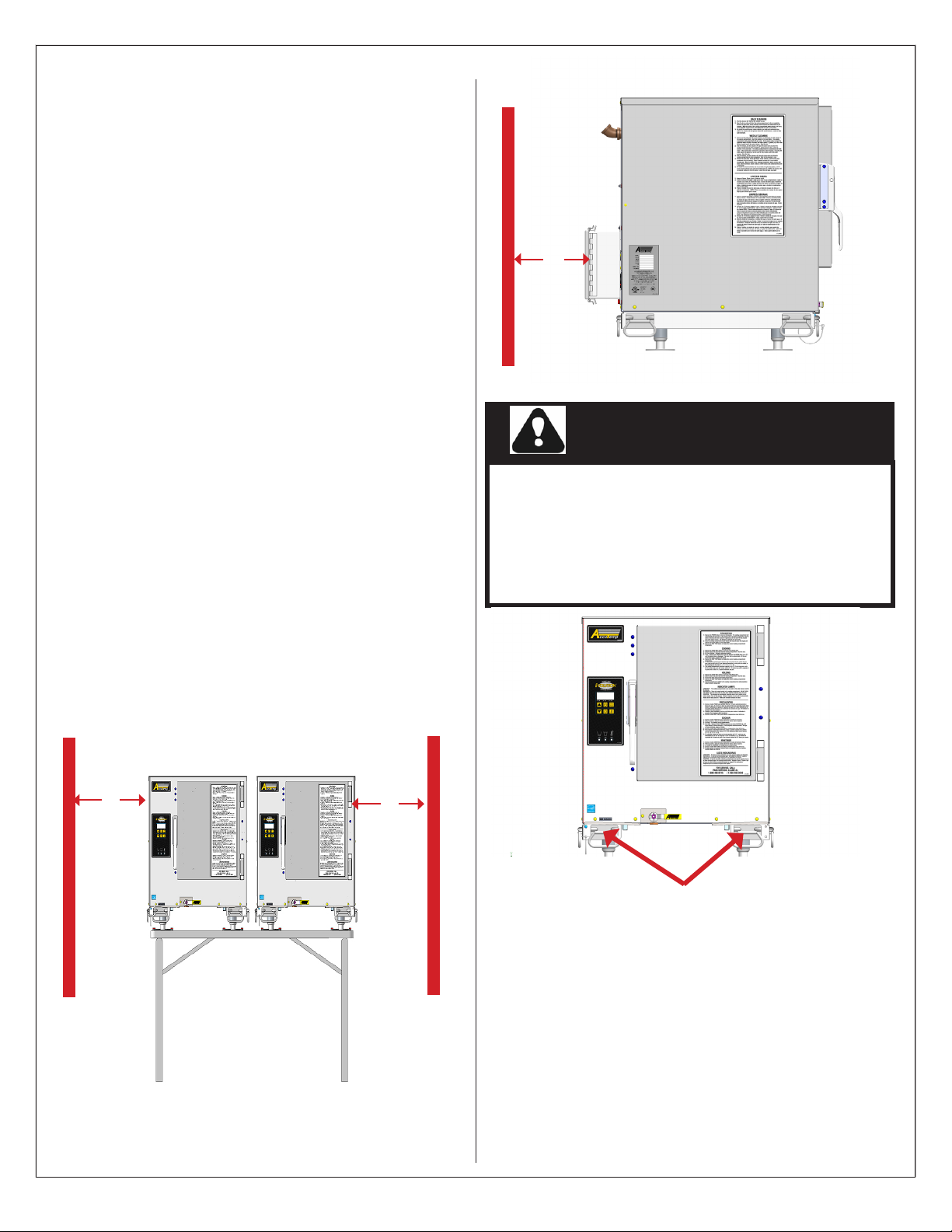
LOCATION AND PLACEMENT
The appliance must be placed on the AT1A-3780- 1
Steamer Table Assembly which is specially designed
for this application. Clearances must be maintained as
indicated for access to the circuit breaker inside the
power pack and for proper operation of the appliance
See Fig. 1 & Fig 2 for clearance specications.
EQUIPMENT CLEARANCE REAR
7”
Fig 2
CAUTION
This appliance is extremely heavy. For safe
handling, the installer should obtain help
as needed or employ appropriate material
handling equipment to remove appliance
from it’s packaging and move it into its nal
location.
EQUIPMENT CLEARANCE SIDES
1”
SP8017-1404
Fig 1
1”
APPLIANCE LIFTING
Appliances are heavy enough to require
additional manpower or powered assistance
when installed on the stand. This model
Evolution incorporates front and side lifting
handles that must be used to lift the appliance
on to the stand. This table has retaining
brackets that the appliance anged feet must
slide into to secure it to the table. See Fig 3
EVOLUTION EEK STEAMER
Fig 3
LIFTING HANDLES
PAGE 3
Page 5
INSTALLATION
WARNING
LEVELING
This appliance must be installed in a level condition.
An out of level condition may cause erratic operation
and damage. Damage of this kind is not covered by
the limited warranty.
The appliance is leveled by screwing in and out the
four anged feet while using a spirit level front to
back and left to right.
The anged feet of the appliance are easier to adjust
if they are not interlocked into the retaining brackets
of the EEK table assembly. However it is possible to
adjust if interlocked into the retaining brackets of the
table assembly.
ELECTRICAL REQUIREMENTS
The AccuTemp Evolution Electric appliance has been
designed, manufactured and tested to meet
or exceed the Underwriters Laboratories safety
standards. To ensure safety is maintained in
your installation, it is important that the following
paragraphs are understood before attempting to
apply power to your appliance. If there is any doubt
as to whether your supply receptacle is of the correct
voltage, amperage, or is properly grounded, consult a
qualied electrician or authorized service agent.
POWER REQUIREMENTS
AC power requirements are listed on the data plate
located on the left side access panel on all Evolutions.
This appliance should never be connected to a
circuit operating at more than 150 VAC to ground
and should always be connected to an individual
branch circuit. Make sure the voltage at the supply
receptacle is within ±10% of the voltage listed on
the Evolution data plate. Connection to any other
voltage may permanently damage your appliance or
cause premature component failure. Damage of this
type is not covered under the product warranty. Each
Evolution Electric appliance for EEK comes equipped
with a power pack and an internal breaker that is rated
for the power requirements of each appliance. Damage
caused by removal or modication of the power pack
is not covered by appliance limited warranty.
Only personnel qualied to work with electricity
should install this equipment. Improper
installation can cause personal injury or damage
to the equipment.
ELECTRICAL INSTALLATION
This appliance is designed with a power pack for
connection to a generator or line power. Always turn
the breaker off at the supply side before connecting
power to the appliance. If a generator is to be
used wait until the generator has stabilized before
connecting power. Connect appliance to power and
turn supply side breaker on and turn on Power Pack
breaker at appliance.
Close and secure the Power Pack.
DANGER
This appliance Must be properly grounded, in
accordance with all National, State and local
electrical codes.
GROUNDING INSTRUCTIONS
Grounding provides a path for electric current to
reduce risk of shock. This product is equipped with a
power pack. The power pack must be plugged into a
receptacle that is properly installed and grounded in
accordance with all National, State and local electrical
codes or in the absence of local electrical codes with
the National Electric Code, ANSI/NFPA 70, or the
Canadian Code, CSA C22.2 as applicable. Under no
circumstances shall the plugs grounding prong be cut
or bent to t a receptacle other than the one specied.
Do not use any adapters.
DANGER
Any in-eld modication made that bypass the
safety features of this appliance will result in
serious injury or death.
WARNING
Any in-eld modications made without written
authorization from AccuTemp Products, Inc. will
void all written and oral warranties.
SP8017-1404
EVOLUTION EEK STEAMER
PAGE 4
Page 6
OPERATIONS
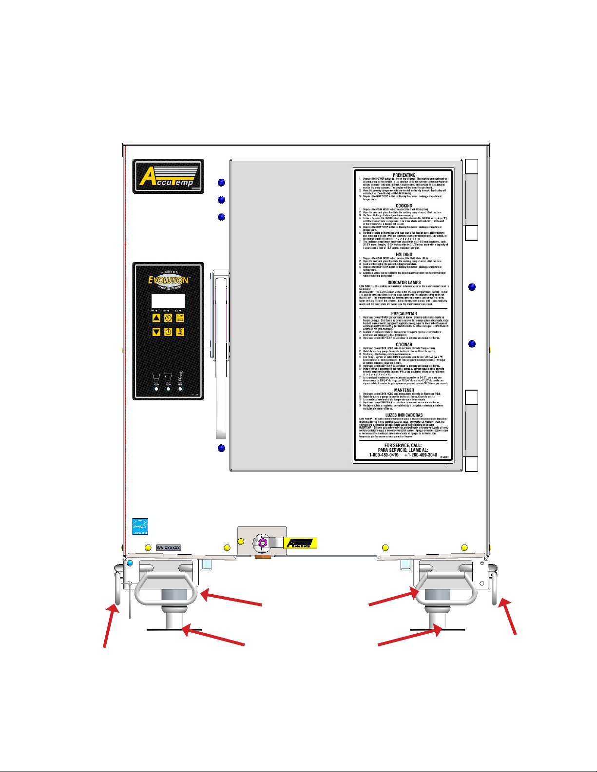
OPERATOR DISPLAY
OPERATING INSTRUCTIONS
& KEYPAD
DOOR LATCH
SIDE LIFT HANDLE
SP8017-1404
DRAIN VALVE
FRONT LIFT HANDLES
ADJUSTABLE FLANGED FEET
FIG 4
EVOLUTION EEK STEAMER
SIDE LIFT HANDLE
PAGE 5
Page 7
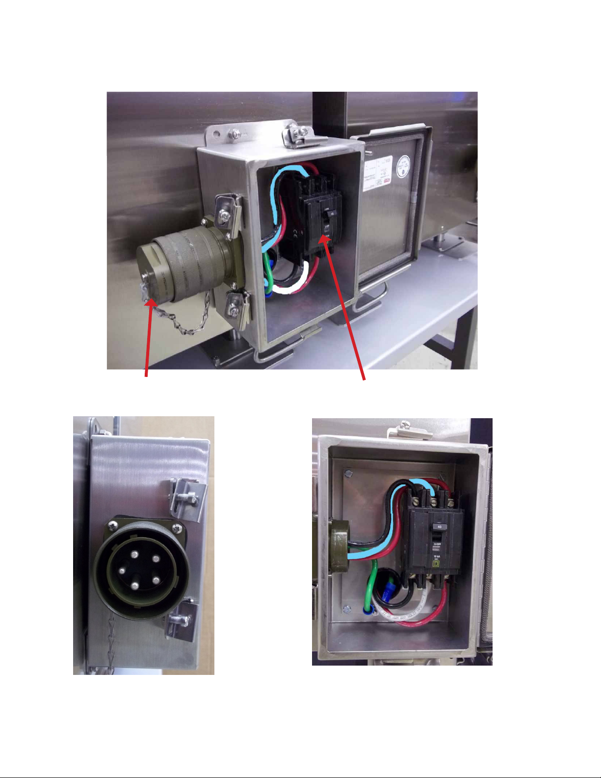
OPERATIONS
POWER PACK
GENERATOR CONNECTION
COVER CAP
CIRCUIT BREAKER
GENERATOR CONNECTION
SP8017-1404
FIG 5
EVOLUTION EEK STEAMER
PAGE 6
Page 8
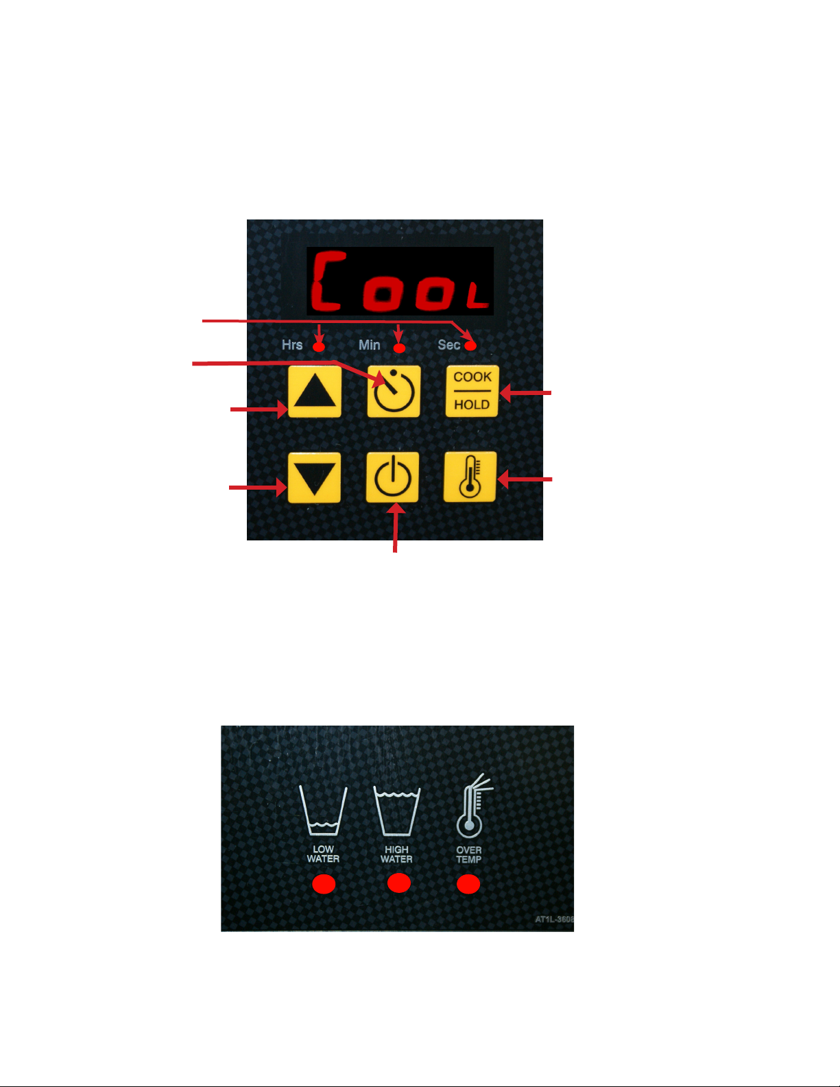
OPERATIONS
HRS/MIN/SEC
TIMER
INDICATORS
TIMER
Keypad & Display
INCREASE TIME
DECREASE TIME
COOK/HOLD
DISPLAY
TEMPERATURE
ON/OFF
FIG 6
Warning Indicators
SP8017-1404
FIG 7
EVOLUTION EEK STEAMER
PAGE 7
Page 9

OPERATIONS
SAFETY WARNINGS
WARNING
When accessing the cooking chamber , be sure to always stand back while slowing opening the door
to allow the chamber to vent off the steam. Never reach into the cooking chamber before it has
completely vented off the steam
Never reach into the cooking chamber or handle hot items without wearing the proper hot gloves.
Steam coming out of the holes on the right side of the cooking chamber are invisible and can cause
severe burns
Never use wet or damp gloves as moisture can conduct heat quickly.
If a cover or covering is used on the cooking pans verify if liquid has accumulated on the top of the
cover or covering. If this has occured use precaution when removing the pan to avoid the liquid
from spilling as it can cause servere burns.
Keep the oor in front of the equipment clean and dry. If spills occur, clean immediately to avoid
potential injuries.
CAUTION
Do not manually ll water above the water level mark on the left side of the cooking chamber.
Do not use abrasive materials, such as wire brushes, metal scouring pads to clean the cooking
chamber bottom.
SP8017-1404
EVOLUTION EEK STEAMER
PAGE 8
Page 10
OPERATIONS
DAILY PREP:
1. Place 4” full size steam table pan or a 1/1
gastronome pan with a minimum depth of 4”.
2. Close the drain valve
3. Fill with 2 1/2 gallons (9.5 Litres) of tap water.
4. Close Door
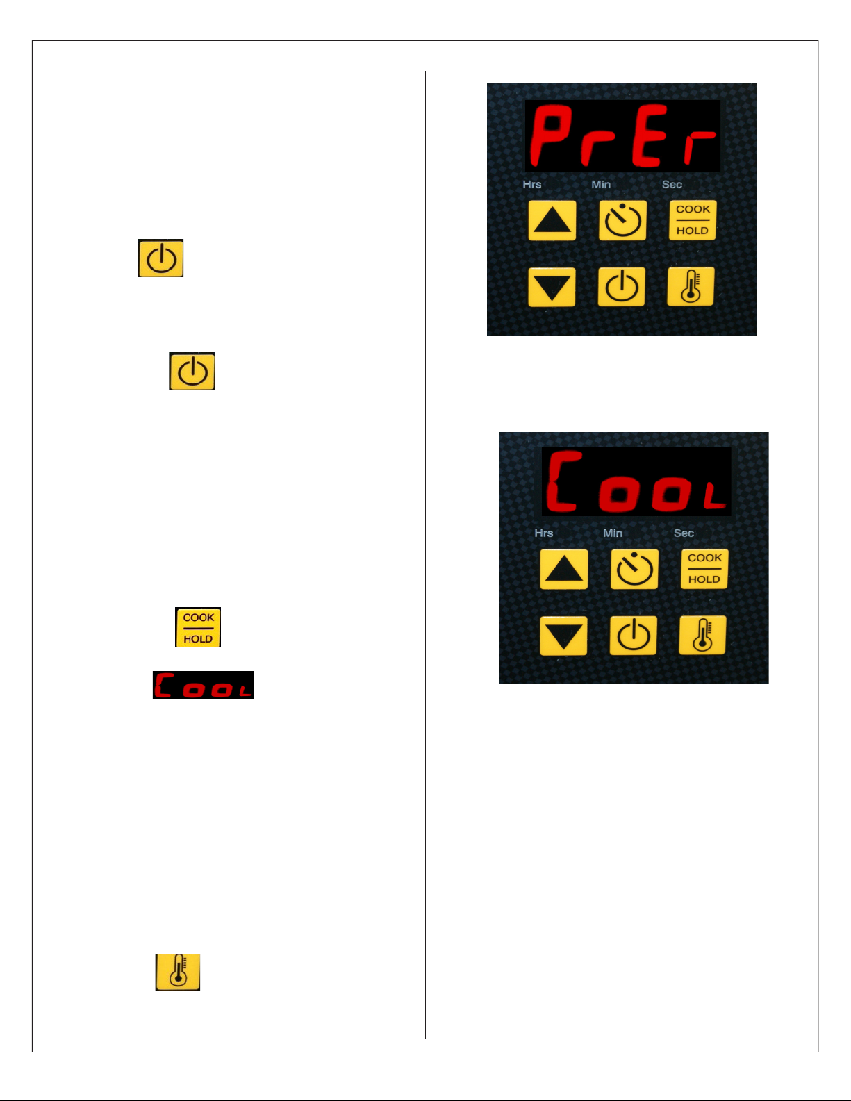
5. Press (On/Off) to start the preheat
process.
PREHEATING ( FIG 8)
1. Depress the (On/Off) key to turn on
the appliance. The display will indicate PrE.
2. Once the appliance is preheated to 195° F
the display will indicate COO (Cook Mode)
3. Place your product into the cooking chamber
starting from the top and working your way
from top to bottom until all 6 pans are in place.
Close the door to start the cooking process.
COOKING ( Fig 9 )
1. Depress the key to select the Cook
Mode (COO). Make sure that the appliance
displays
2. Open the door and place food into the
cooking chamber. Loading the pans from top
to bottom until all 6 pans 2 1/2” steam table
pans are in place. Close the door to start the
cooking process. For Partial Loads see Page
11, Fig 12.
Fig 8
Fig 9
3. Timer — Depress the TIMER button and
depress the ARROW keys [▲ or ▼] until the
desired time is displayed. The timer starts
automatically. At the end of the timed cycle, a
beeper will sound.
4. Press the key at any time to display
the current cooking chamber temperature.
SP8017-1404
EVOLUTION EEK STEAMER
NOTE:
The highest cooking temperature with no
product in the appliance is 212 °F(100°C)
at sea level. Higher elevations will decrease
the cooking temperature.
PAGE 9
Page 11
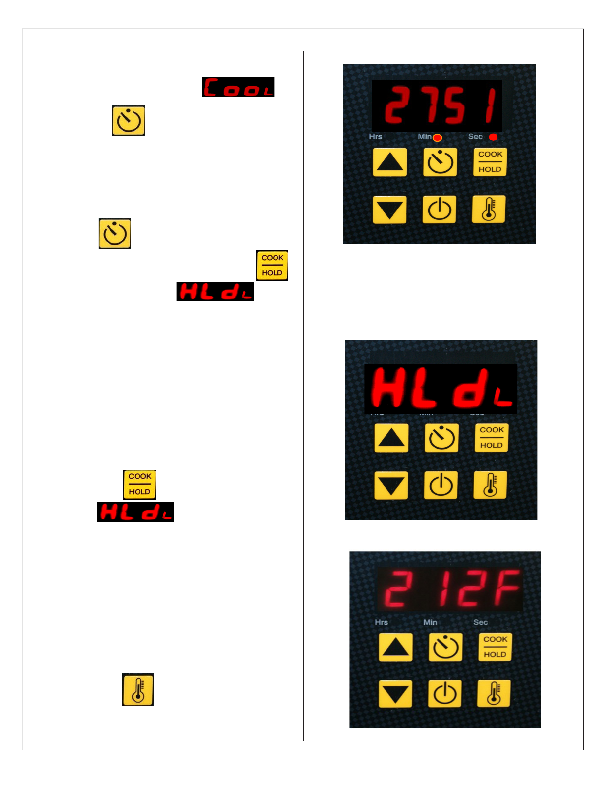
OPERATIONS
Timed Cooking (Fig 10)
1. Verify that the display reads
2. Depress the key to start the timer in the
default time.
3. To adjust depress the ARROW keys [▲ or ▼]
until the desired time is displayed. The timer
starts automatically and at the end of the timed
cycle a beeper will sound.
4. Press the key to silence the beeper.
To stop the cooking process press the
key until display reads
The food will be held at the default temperature
of 180°F(82.2°C)
Fig 9
HOLDING ( Fig 11 )
In “Hold” the appliance temperature is set for
180° F from the factory. The hold temperature
can be changed to a single value for
temperatures ranging from150° F to 190° F. (See
page 17 for programming this function).
Hold can also be used during downtimes to save
energy and water while keeping the appliance
preheated.
1. Depress the key to select the Hold
Mode
2. Open the door and place food into the
cooking chamber. Shut the door.
3. Food will be held at the preset holding
temperature. The factory default setting is set
at 180° F(82.2°C).
4. Depress the DISP TEMP button to
display the current cooking chamber
temperature.
Fig 10
DISPLAYING TEMPERTURE( Fig 12)
1. Depress the key to display the current
cooking chamber temperature chamber.
SP8017-1404
EVOLUTION EEK STEAMER
Fig 11
PAGE 10
Page 12
OPERATIONS
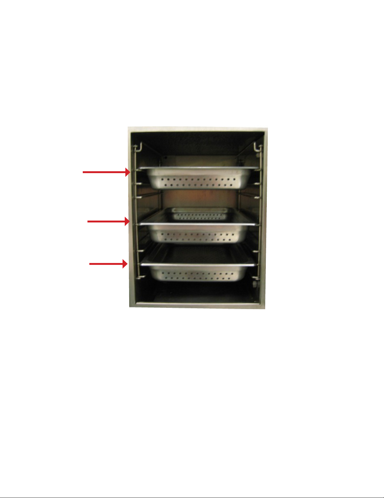
PARTIAL LOADS
The Evolution is designed to cook quickly with exceptional pan-to-pan uniformity on full loads of food.
Excellent pan-to-pan uniformity can be achieved with partial loads if the pans are optimally placed in
the appliance. For partial loads using 2½” deep pans, the top position in the appliance is used rst
followed by the second pan placed in third pan position from the top and then the third pan in the fth
pan position from the top. Placing the pans in these positions will optimize the cooking time and panto-pan uniformity. See Fig 13
1st PAN
2nd PAN
3rd PAN
Fig 13
DAILY PREPARATION FOR USE - CONNECTIONLESS MODEL
Preparing the Evolution Connection-Less model for use each day requires very little time and effort.
Simply verify that the appliance is clean, the drain valve is in the closed position and the cooking
chamber is lled with approximately 2½ Gallons of tap water. Close the door and push the ON/Off key
on the keypad. The water level will need to be monitored and lled as required. Do not use the low
water warning lamp as the indicator to check the water level as this can damage the appliance over
time.
SP8017-1404
EVOLUTION EEK STEAMER
PAGE 11
Page 13
OPERATIONS
CLEANING
The following cleaning instructions are for typical operations. A higer frequency of the weekly cleaning
procedure may be required for high volume users and after protien prepartion. Failure to follow the cleaning
instructions may cause slower cooking times and intermittent operations of the appliance. It is recommended
that the door is left open after cleaning to extend the life of the gasket materials.
MATERIALS REQUIRED
White vinegar
Dishwashing liquid
Non-metalic scrubing pad
5 Gallons tap water
Cleaning towels
High quality stainless steel cleaner and polish.
Warning: Do not use a water jet
or pressure washer to clean the
appliance
DAILY CLEANING
1. Turn the appliance off and wait for the appliance and water reserve to cool.
2. Open the drain valve and allow the cooking chamber to drain completely. Remove the pan rails and
steam collector (Fig 14) Wipe the inside of the cooking chamber, water sensors, pan rails and steam
collector with a clean cloth. Clean the door gasket, inside of door and front face of the cooking chamber.
3. Install the steam collector and pan rails. Once the water in the drain pan has sufciently cooled
empty the drain pan wipe down and replace. Leave the door and drain valve open overnight.
WARNING
4. Clean the exterior with soap and clean tap water and a use a high quality stainless steel cleaner.
WEEKLY CLEANING
1. Close the drain valve and add 1 cup (8 ounces or 0.24 liters) of white vinegar to the cooking chamber
and ll with approximately 2½ Gallons of tap water , shut the door and turn the appliance on.
2. After 15 minutes, turn the appliance off and allow the appliance and water reserve to cool. Open the
drain valve and allow to drain completely.
3. To rinse close the drain valve, ll with approximately 2½ gallons tap water, close the door and turn the
appliance on. Let it run for 15 minutes, turn the appliance off and allow the appliance and water reserve
to cool. Open the drain valve and allow the cooking chamber to drain completely.
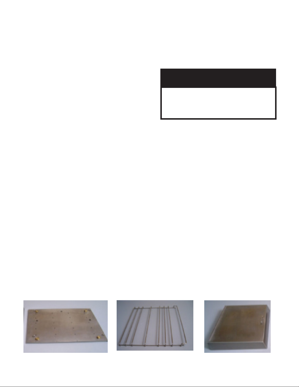
4. Remove the pan racks, steam collector and steam distributor for cleaning. Clean the upper and lower
water sensors with a non-metallic cleaning pad. Wipe the inside of the cooking chamber, water sensors,
pan rails (Fig 14),steam distributor front and back (Fig. 14), steam collector top, bottom and sides (Fig.
14).
5. Install the steam collector rst, resting the steam distributor on top of the collector align the retaining
fasteners and hand tighten and then install the pan rails. Once the water in the drain pan has suffently
cooled empty the drain pan and wipe down and replace. Leave door and drain valve open overnight.
Steam Distributor
Pan Rail
Steam Collector
SP8017-1404
Fig 14
EVOLUTION EEK STEAMER
PAGE 12
Page 14

BASIC TROUBLESHOOTING
WARNING LIGHTS
LOW WATER — The steamer is low on water or
the water sensors need to be cleaned.
HIGH WATER (CONNECTED MODELS ONLY)
Not Utilized on this model
OVER TEMP — The appliance has overheated.
It may have run out of water. Carefully open the
door, allowing steam to escape and then check
the water level in the bottom of the steamer If
it is nearly empty, Clean the water level sensor
probes (white buttons) located in the front left
corner and the wall immediately around them
being careful not to get burned (protective
gloves are strongly recommended). Refill the
steamer with 2 1/2 gallons of tap water and
restart
Food Is Under Cooked
Try using perforated pans as they allow steam
to penetrate from all directions, maximizing
heat transfer and giving you the shortest
cooking times. Try distributing the product
more evenly within the appliance and or pans,
if possible.
Make sure the water drain valve on the front
of the Evolution is tightly closed.
The steamer may appear to be cooking normally
if the valve is slightly open but efciency may
be compromised.
Check the door seal for food debris. Food
debris on the face of the door seal or under ap
may cause steamer to appear to be cooking
normally but efciency may be compromised.
Nicks or cuts in the door seal may also cause
inefcient cooking.
If the steamer has plenty of water, allow it to cool.
This normally takes a few minutes. When the
Over Temp light goes out, restart the steamer.
Food Is Over Cooked
Check that the proper cook time is being used.
Food Is Under Cooked
Make sure you are using adequate time
a. Extra time may be required if pans are
covered or if product is left in plastic bags
or similar packaging.
Make sure the door is closed. When the
door opens the heat is turned off until it
is shut
Make sure the steamer is in the Cook Mode;
Push the Display Temperature button to
ensure the steamer is at the boiling point
of water taking into account your elevation
above sea level. If it isn’t the appliance
maybe in the Hold Mode. Variations
in temperature can also be caused by
frozen product just being put in or with the
connected model a fresh measure of tap
water was activated. These will shortly
come up to temperature as long as the door
is closed.
Steamer won’t come on
Verify that the breaker in the power pack is in
the active position
Verify that the power pack is plugged in
Steamer doesn’t heat
If the operator’s display doesn’t light up, See
section“ Steamer won’t come on”.
Verify the steamer door is closed, as the
heat won’t turn on if the door is open.
Steam comes out the door
Verify that the door is completely closed and
latched.
If the appliance was just lled with water, wait
a minute to see if it stops. After the steamer is
relled with water it is normal for some steam
to come out the door for a brief amount of
time, usually less than one minute.
Steamer Temperature is low
Make sure door is closed
Verify that the low water light isn’t on
Verify the appliance is in the Cook Mode not
the Hold Mode
SP8017-1404
EVOLUTION EEK STEAMER
PAGE 13
Page 15
SERVICE INFORMATION
SP8017-1404
EVOLUTION EEK STEAMER
PAGE 14
Page 16
PURPOSE REFERENCE OF MAIN COMPONENTS
Component Part # Purpose
Auto-Fill Valve
(OPTIONAL)
AT1A-3841-1
Reed Switch:
Water Over-Fill
AT0A-3519-2
Sensor Switch
(OPTIONAL)
Float Ball:
AT0P-3233-1
Control Relay #1
(AC)
AT0E-2825-5
Door Switch AT0A-3660-1
S#: 34769 & Up
Chamber
Pressure Switch
AT0E-3617-2
S#: 34768 & Lower
AT1A-3847
• Solenoid Valve that allows water to ow into the steam chamber; that
is controlled automatically by the Water Board based on inputs from
the Water Sensor Probes.
• Magnetic Reed Switch is used in conjunction with a Float Ball. If the
water rises too high, the switch opens and turns off the steamer.
• When the switch opens, the High Water Overll LED will light. The
user will have to drain the water out and turn the steamer back ON;
otherwise, the steamer will remain shutdown.
• Controls AC Volt input & output signals which provide actions from
the Water Sensor Board and Auto-Fill Valve (if installed).
• Magnetic Switch used to ensure that the door is closed and latched
prior to generating steam
• Solid State Relay(s) will not activate if this switch is not closed
(Door Open).
• Normally closed switch that allows pressure to build-up inside the
steam chamber.
• Opens when the steam chamber pressure reaches 1/2 PSI.
• Solid State Relay(S) will not activate if this switch is not closed
(Switch Open).
Solid State Relay AT0E-2059-3
6 KW:
AT1A-3530-1
8 KW:
AT1A-3530-2
10 KW:
Cast Heater
Replacement Kit
AT1A-3530-3
12 KW:
AT1A-3530-4
14 KW:
AT1A-3530-6
17 KW:
AT1A-3530-7
• Provides line voltage to the Cast Heater elements, once the Controller
/Keypad Board sends the 24V control signal to the relay(s).
• The relay(s) are only activated if the Door Switch & Chamber
Pressure Switch are closed.
• The number of Solid State Relays used, depends on the phase and
wattage needs of the unit.
• Transfers the heat, generated from the internal elements; to boil the
water to create steam.
• Cast Heater can be wired to single or 3 phase; and have a parallel,
delta, or wye conguration.
• Cast Heater must be replaced with the same wattage heater as
specied in the model number.
SP8017-1404
EVOLUTION EEK STEAMER
PAGE 15
Page 17

PURPOSE REFERENCE OF MAIN COMPONENTS
Component Part # Purpose
Contactor
(3 Pole)
AT0E-1587-4
Transformer AT0E-2662-5
12KW & Lower
Overtemp Switch
AT1E-2653-3
(Thermal Limit
SW3)
14KW & Up
AT1E-2653-4
Control / Keypad
Board
Water Sensor
Control Board
AT0E-3625-1
AT0E-3230-2
• Provides line voltage to the Solid State Relay(s), when the contactor’s
coil is closed by the control signal sent from the Water Control Board.
• Provides line voltage to the Transformer.
• Steps-down the Supply Line Voltage to 24 -28VAC.
• Normally closed switch that provides a safety feature to the machine
in case the Cast Heater overheats.
• If the Cast Heater overheats, the switch will open and turn the steamer
off; while lighting the red LED Overtemp Light on the Control Panel.
• The steamer will not turn on until the temperature has dropped
enough to allow the Overtemp Switch to close again.
• Human interface for steamer operations through push-buttons,
operations, & display readouts.
• Provides power to the Solid State Relay(s) (24VDC).
• Receives input from the Temperature (RTD) Sensor and displays the
water temperature on the LED readout.
• Maintains the preset HOLD temperature.
• Receives inputs from Water Sensor Probes and implements
corresponding actions for those inputs based on the water level in the
steam chamber.
• Controls the Auto-Fill Valve (if installed) and receives inputs that
provides actions for the desired water level needs.
• Teon exterior with a stainless steel center that uses the minerals
Water Sensor
Probe
AT1E-2652-1
in the water to complete the electrical circuit to the Water Control
Board.
• MUST BE CLEAN TO WORK PROPERLY.
• Once the Low Water Sensor is satised, it will allow the Solid State
Low Water Level
Probe
Relay(s) to activate.
• If the water level is below the sensor, the Water Board will activate
the Auto-Fill Valve (if installed) lling the unit the water until the
High Limit Water Sensor is satised.
• On initial chamber water ll, once the water level reaches and
satises the Operational Water Sensor, the Water Board will keep the
Auto-Fill Valve open for 30 additional seconds..
High Limit
Water Level
Probe
• After initial chamber water ll, when the water level drops below the
sensor’s operational level; the Water Board will open the Auto-Fill
Valve for 30 seconds to raise the water level back above the High
Limit Water Sensor.
• This process will repeat as long as the water level stays above the
Low Water Sensor.
SP8017-1404
EVOLUTION EEK STEAMER
PAGE 16
Page 18

PURPOSE REFERENCE OF MAIN COMPONENTS
Component Part # Purpose
Temperature
(RTD)
Sensor
Door Assembly AT1A-3600-1
Drain Valve AT1P-2239-1
AT0E-3626-1
ADDITIONAL COMPONENT PART NUMBERS
Component Part # Component Part #
Pilot Lamp, 24V Red AT0E-1800-2 Door Hinge (Pair) AT1H-2058-3
Fuse, 1.25A 250V AT0E-2731-2 Door Latch Assy, Ceramic Magnet AT1H-3609-1
• Provides temperature input to Control/Keypad Board, which displays
the temperature in the steam chamber based on resistance changes
from the Temperature (RTD) Sensor.
• Used to maintain the preset HOLD mode temperature.
• Keeps the steam trapped inside the steam chamber to allow pressure
to build and cycle the Chamber Pressure Switch.
• Manually Open/Close valve used to drain water from the steam
chamber.
Gasket, Door AT1G-2633-1 Door Latch Mounting Plate AT1M-3046-1
Inner Door Assembly AT1A-3647-1
SP8017-1404
EVOLUTION EEK STEAMER
PAGE 17
Page 19

SEQUENCE OF OPERATION
INDICATORS AND WATER CONTROL BOARD OPERATION:
PWR Button Pushed & Water Level Is Below the Low Water Level Sensor
• The Low Water Light Indicator will be ON and Alarm will sound.
• PRE is displayed on the Control/Keypad Board.
• (The red LED light on the Water Sensor Board will be ashing continuously.)
PWR Button Pushed & Low Water Level Sensor Is Satised
• The Low Water Light Indicator and Alarm (only manual ll units use an alarm for low water
condition), will be OFF.
• This is minimum water level needed for the Contactor to close and turn the Cast Heater ON.
• (The red LED light on the Water Sensor Board will have about a 1 second ash delay.)
CAST HEATER GENERATING HEAT OPERATION:
Power Cord Plugged-In & PWR Button Not Pushed
• Line Voltage comes into the 3 Pole Contactor’s L1 - L3 terminals. (Refer to the unit’s
specic wiring schematics to determine the wire color to “L” Terminal location.)
• Line Voltage is then taken off of L1 & L2 of the Contactor and applied to the Transformer,
which steps-down the Line Voltage to 24VAC.
• From the two, 1.25Amp, fuses; power goes through the Overtemp Switch, then goes to
the Water Sensor Board, to Control Relay #1 (CR#1) coil, to the High Water Overll Reed
Switch (Auto-Fill Only), to the Control/Keypad Board, and to Pin 6 of CR#1. Power also
ows through CR#1, Control/Keypad Board, Water Sensor Board and Contactor (once the
water level condition is met).
• (The red LED light on the Water Sensor Board will be ashing continuously.)
PWR Button Pushed & Low Water Level Sensor Is Satised
• (The red LED light on the Water Sensor Board will have about a 1 second ash rate.)
• The Water Sensor Control Board’s K2 Relay will close, sending power to the Contactor’s
coil; closing the contacts and allowing Line Voltage to be sent to the normally open Solid
State Relay(s).
• The Control/Keypad Board will send a 24VAC signal to the Solid State Relay(s); closing the
Relay(s) (as long as the Door Switch and the Chamber Pressure Switch are closed).
• The Solid State Relay(s) then pass Line Voltage to the Cast Heater’s Elements generating
heat evenly over the bottom of the steam chamber; creating steam for cooking.
SP8017-1404
EVOLUTION EEK STEAMER
PAGE 18
Page 20

SEQUENCE OF OPERATION
Temperature Sensor (RTD) and Control/Keypad Board
• As the water temperature rises, the RTD will provide a signal, based on the resistance of the
sensor, to the Control/Keypad Board to provide a digital temperature display.
• Control Panel will show PRE (Preheat) on initial start-up until the steam chamber reaches
195°F, then COO (Cook) will be displayed between 195°F and 212°F.
• The operating default mode on initial PWR ON is COOK mode; which automatically causes
the steamer to go to the normal operating boiling point, which is 212°F at sea level.
• In COOK mode, the 24VAC output from the Control/Keypad Board is continuously on, so
that the unit’s temperature is controlled by the Chamber Pressure Switch, which opens at 1/2
PSI (13.9 “ water column) or higher.
• In HOLD mode (HLD), the steamer’s regulated temperature will change to the HOLD
temperature’s preset value. The Control/Keypad Board will regulate temperature via the
RTD input, based on the current HOLD mode preset value. (This value can be changed
using the program function on the Control/Keyboard Control.)
SP8017-1404
EVOLUTION EEK STEAMER
PAGE 19
Page 21

MODIFYING CONTROL / KEYPAD PROGRAM SETTINGS
Hrs/Min/Sec
LED Lights
UP Arrow
DOWN Arrow
S1 - Increase Program Item (Will cycle the Hrs/Min/Sec LED light)
S4 - Decrease Program Item (Will cycle the Hrs/Min/Sec LED light)
S3 - Increase Program Value (Will change the Digital Readout display)
S6 - Decrease Program Value (Will change the Digital Readout display)
S2 - Exit & Save
ENTERING PROGRAM MODE: Simultaneously, depress and hold S4 & S6 for minimum of 8 seconds or
until the Hrs LED blinks and the display shows a Hold Temp number (default is 180°F). Now the Controller
can operate under the Program Function Parameters.
S1
S4
POWER
S5
S2
TIMER
S3
S6
COOK/HOLD
TEMP Display
Program Mode Function Parameter Table
Hrs LED Min LED Sec LED PARAMETER MIN MAX ELECTRIC
Blink OFF OFF HOLD Temp Value = Degree F MIN Temp MAX Temp 180
ON OFF OFF Default Timer Value = Hours 0 8 0
OFF ON OFF Default Timer Value = Minutes 0 59 30
OFF OFF ON TEMP Probe Offset = Degree F 0 50 0
ON ON ON TEMP Probe Offset = Neg/Pos Diff NEG = 1 POS = 0 0
Blink Blink Blink Hysteresis
ON Blink Blink TEMP Regulating Mode
Blink ON Blink Proportioning BAND TIME 4 10 10
Blink Blink ON Proportioning BAND WIDTH 4 10 10
TO RESET CONTROLLER TO FACTORY DEFAULT VALUES,
PRESS AND HOLD S4, THEN PRESS S5.
SP8017-1404
EVOLUTION EEK STEAMER
2 10
On/Off = 0 PID = 1
2
1
PAGE 20
Page 22

START
TROUBLESHOOTING FLOW-DIAGRAM
POWER
ON
NO
Steamer
Plugged-In
YES
Breaker
ON
YES
Check
Internal
Power
Voltages
SEE C
Component
Voltages
Correct
YES
Call
AccuTemp
Service
NO
NO
NO
YES
SEE
SEE
SEE
A
B
D
WARNING
LIGHTS
YES
Control Panel
Error Code
NO
Low Water
Light
NO
Over Temp
Light
NO
High Water
Light
YES
Float Ball
Installed
YES
Call
AccuTemp
Service
YES
YES
YES
NO
NO
SEE
SEE
SEE
SEE
E
F
G
H
STEAMER
HEATING
YES
Temp
Low
NO
Steam Out
The Door
NO
Food Over
Cooked
NO
Food
Under
Cooked
YES
Different
Problem
With
Steamer
Operations
YES
NO
YES
YES
YES
YES
NO
SEE
I
SEE
J
SEE
K
SEE
L
SEE
M
DONE
WITH
CHART
Call
AccuTemp
Service
(800) 480-0415 or service@accutemp.net
Call
AccuTemp
Service
SP8017-1404
EVOLUTION EEK STEAMER
PAGE 21
Page 23

REF
FLOW-DIAGRAM REFERENCE TROUBLESHOOTING CHART
LETTER
POSSIBLE CAUSE EVALUATION
A Power Cord Disconnected
B Breaker Is Tripped
Transformer
Conrm proper voltage is present at receptacle.
Plug-in Power Cord.
Unplug steamer and check voltage at receptacle.
Reset Breaker
Check for proper incoming voltage to the primary side
and 24V on the secondary side.
C Fuses Check for continuity.
Over-Temp Switch
Control panel not responding.
Check between the common wire, terminal # 6 on the
control relay and the brown wire after the fuse.
Check for 24VAC incoming power at pins J2-1 & J2-2.
Check for out put at pins J7-3 & J7-4 - 24VAC ON/OFF
Check the wiring to the component; including the
D Bad Component or Faulty Wiring
wire-to-connectors, GND’s, and damage.
If component O/P bad, then may need replaced.
E
Error Code: -1F or -99F for RTD
probe.
Check for 1000 ohms (at room temp) on Digital
Controller Board on J3 - Pins 1 & 2.
EC: -1F = Open sensor EC: -99F = Shorted sensor
F Low Water Sensor Not Being Met
G Steamer Has Over-Heated
Too Much Water In Steam Chamber
H Operational Water Level Sensor Faulty
Float Ball & Reed Sensor Faulty
Ensure water is at the max water level line inside the
steam chamber.
Ensure that the Low Water Sensor is cleaned and that
the Water Board is working properly.
Check that the water level inside steam chamber is not
empty; and rell if needed.
If an Auto-Fill unit, then ensure that water supply is not
shut-off.
Ensure Water Sensors are clean.
DO NOT OPEN DOOR!
Open Drain Valve until the High Water Light goes off.
If light DOES NOT go out and no water in steamer,
then possibly a sensor fault.
Ensure the top Water Sensor is clean.
Check that Water Board is working properly.
Ensure Float Ball is not stuck on the Sensor Post.
Ensure Sensor Post & inside of the Float ball is clean.
Check continuity of the Reed Switch (Float over sensor
creates continuity; Float off sensor creates open.)
SP8017-1404
EVOLUTION EEK STEAMER
PAGE 22
Page 24

FLOW-DIAGRAM REFERENCE TROUBLESHOOTING CHART
REF
LETTER
POSSIBLE CAUSE EVALUATION
Control Panel Check for 24VDC output (J7 Pins 1 & 2).
Ensure Door is shut and handle is latched.
Door Switch Not Engaging
Check the Door Switch for continuity with Door closed.
Check the butt splices and wire connections for good
crimps.
Chamber Pressure Switch
Switch is normally closed.
Check the Chamber Pressure Switch for continuity.
Relay is normally open.
Time Delay Relay #1 (5 sec)
Check for continuity during the rst 5 -10 secs of
pressing PWR ON button.
Check for 24-30VDC at Pins 7 & 8 on the CR2 Coil.
Control Relay #2
Check for 24VAC on pin 3.
Ensure Relay Contacts are closing and not stuck open.
Switch is normally open.
Fan Pressure Switch
Check that switch closes at .2” Water Column (WC) &
that voltage is present on Lt Blue wire to Spark Module
at pin PSW.
Check that the vent is set for:
Power Burner Fan
3.5” for Natural Gas & 3” for Propane.
If vent is to large, then unit will not ignite.
I
Check the Red LED light on the module for the
following indications (listed on the module):
Ignition (Spark) Module
Constant ON red LED = Bad Ignition Module.
1 Flash = Air Vent Blockage.
2 Flashes = Flame with No Call For Heat
3 Flashes = Ignition Lookout (No Gas Present)
Check that the probes are not oxidized or broken.
Check that the Ignition Cable has a good connection to
Ignition Probe & Cable
Ignition Probe.
Verify that the Ignition Probes are in the correct position to the Burner’s surface as required.
Check to ensure that the Time Delay Relay #2 is
Gas Enrichment Valve
opening the Gas Enrichment Valve for 4 secs.
(Signal from Spark Module out of pin V1.)
Ensure that the valve is engaging.
Gas Valve Control
Check that the Gas Pressure is at the correct WC value:
5” for Natural Gas & 10” for Propane.
Verify that the incoming gas pressure from the External
External Supply Gas Press. Regulator
Regulator is between WC values:
7” - 10” Natural Gas & 11” - 13” Propane.
SP8017-1404
EVOLUTION EEK STEAMER
PAGE 23
Page 25

LOCATION OF ELECTRICAL COMPONENTS
Solid
State
Relays
&
Heat
Sinks
Power Cord Contactor
Chamber Pressure Switch
Heater/PWR
Terminal Strip
Control/
Keypad
Board
Water Sensors
Transformer Fuses Water Sensor
Control Board
SP8017-1404
EVOLUTION EEK STEAMER
Control
Relay #1
PAGE 24
Page 26

ELECTRICAL COMPONENTS REMOVAL & INSTALLATION
CORD & PLUG ASSEMBLY
1. Unplug the Unit.
2. Remove the Left-Side Panel by removing the
Sheet Metal Screws holding it in place.
3. Disconnect the Power Cord Leads (Black,
White, Red, and/or Green) from L1-3 of the
Contactor (note the wire color to its location
terminal).
4. On the inside of the unit, remove the retaining
nut on the threads of the Power Cord Cable
Fitting & pullout the Power Cord.
5. Re-install in reverse order.
FUSES
1. Unplug the Unit.
2. Remove the Left-Side Panel by removing the
Sheet Metal Screws holding it in place.
3. Pry the Fuses out of the Fuse Block with a
at-head screwdriver or fuse puller.
4. Re-install in reverse order.
CONTACTOR
1. Unplug the Unit.
2. Remove the Left-Side Panel by removing the
Sheet Metal Screws holding it in place.
3. Disconnect the wires (note the wire color to its
location terminal).
4. Remove the 2 mounting nuts and then remove
the Contactor.
5. Re-install in reverse order.
SP8017-1404
EVOLUTION EEK STEAMER
PAGE 25
Page 27

ELECTRICAL COMPONENTS REMOVAL & INSTALLATION
TRANSFORMER
1. Unplug the Unit.
2. Remove the Left-Side Panel by removing the
Sheet Metal Screws holding it in place.
3. Disconnect the wires (note the wire color to its
location terminal).
4. Remove the 2 mounting nuts and then remove
the Transformer.
5. Re-install in reverse order.
WATER SENSOR CONTROL BOARD
1. Unplug the Unit.
2. Remove the Left-Side Panel by removing the
Sheet Metal Screws holding it in place.
3. Disconnect the wires (note the wire color to its
location terminal).
4. Carefully, push in the locking leg on the 4
plastic posts while pulling the Water Board up
off the posts (note the board’s orientation).
5. Remove the Water Board.
6. Re-install in reverse order.
CONTROL RELAY #1
1. Unplug the Unit.
2. Remove the Left-Side Panel by removing the
Sheet Metal Screws holding it in place.
3. Disconnect the wires (note the wire color to its
location terminal).
4. Remove the 2 mounting screws and then
remove Control Relay #1.
5. Re-install in reverse order.
SP8017-1404
EVOLUTION EEK STEAMER
PAGE 26
Page 28

ELECTRICAL COMPONENTS REMOVAL & INSTALLATION
WATER SENSORS
1. Unplug the Unit.
2. Remove the Left-Side Panel by removing the
Sheet Metal Screws holding it in place.
3. Open the door and ensure that all the water is
drained from the steam chamber.
4. Disconnect the wire from the backside of the
Water Sensor (access via left-side panel).
5. Remove the retaining nut that mounts the Water
Sensor to the Steam Chamber.
6. Push the Water Sensor through the hole in the
steam chamber from the backside.
7. Re-install in reverse order. Torque Sensor
Nuts to between 12-15 In-Lbs.
CONTROL / KEYPAD BOARD
1. Unplug the Unit.
2. Remove the Left-Side Panel by removing the
Sheet Metal Screws holding it in place.
3. Disconnect the wires (note the wire color to its
location terminal).
4. Remove the 7 mounting nuts and then remove
the Control Panel CCA.
5. (If accessing the Program Mode is needed, go
to page 8 for more details.)
6. Re-install in reverse order.
SP8017-1404
EVOLUTION EEK STEAMER
PAGE 27
Page 29

ELECTRICAL COMPONENTS REMOVAL & INSTALLATION
DOOR SWITCH
Door Latch on the Left-Hand Side
1. Unplug the Unit.
2. Remove the Left-Side Panel by removing the
Sheet Metal Screws holding it in place.
3. Disconnect the probe wires: Control/Keypad
Panel J7 Pin 1 & the White/Brown wire from
the Chamber Pressure Switch (the wires to the
location pins are enter-changeable).
4. Push back the insulation, so you can access the
other mounting nut to be removed.
5. Remove the 2 mounting nuts and then remove
the Door Switch. Fg 15
6. Re-install in reverse order.
Fg 16
Fg 15
Door Latch on the Right-Hand Side
1. Unplug the Unit.
2. Remove the Left-Side, Right-Side, and Top
Panel by removing the Sheet Metal Screws
holding it in place.
3. Disconnect the probe wires: Control/Keypad
Panel J7 Pin 1 & the White/Brown wire from
the Chamber Pressure Switch; and pull the
wires up, over the top of the steamer (the wires
to the location pins are enter-changeable).
4. Remove the insulation on the right side, to
access the Door Switch to be removed. Fg 16
5. Remove the 2 mounting nuts and then remove
the Door Switch. Fg 17 Re-install in reverse
order.
Fg 17
SP8017-1404
EVOLUTION EEK STEAMER
PAGE 28
Page 30

ELECTRICAL COMPONENTS REMOVAL & INSTALLATION
CHAMBER PRESSURE SWITCH
1. Unplug the Unit & remove the Left-Side Panel
by removing the Sheet Metal Screws holding it
in place.
2. Disconnect the Wiring Terminals from the
Chamber Pressure Switch (note the wire color
to its location terminal).
3. Remove the hose clamp and disconnect the
hose from the Chamber Pressure Switch.
4. Remove the 2 mounting nuts holding the
Chamber Pressure Switch to chamber cavity.
5. Remove the Chamber Pressure Switch
6. Re-install in reverse order.
SOLID STATE RELAY (SSR)
1. Unplug the Unit.
2. Remove the Left-Side Panel by removing the
Sheet Metal Screws holding it in place.
3. Disconnect the wires for the desired SSR
being replaced (note the wire color to its
location terminal).
4. Remove the thread-cover nuts on the back of
the steamer, while removing the 2 mounting
bolts holding the SSR Assy to the inside-back
of the component chamber; and then remove
the desired Solid State Relay.
5. Re-install in reverse order.
SP8017-1404
EVOLUTION EEK STEAMER
PAGE 29
Page 31

ELECTRICAL COMPONENTS REMOVAL & INSTALLATION
TEMPERATURE (RTD) SENSOR
1. Unplug the Unit.
2. Remove the Left-Side, Right-Side, and Top
Panel by removing the Sheet Metal Screws
holding it in place.
3. Disconnect the probe wires from the Control/
Keypad Panel and pull them from the left, over
the top, to the steamer’s right-side (the wires
to the location pins are enter-changeable).
4. Remove the mounting nut and then remove the
Temperature (RTD) Sensor.
5. Re-install in reverse order. Ensure Thermal
Paste is applied to the Temperature (RTD)
Sensor.
OVERTEMP SWITCH (THERM LIMIT SW3)
1. Unplug the unit.
2. Using an additional person, turn the unit
upside-down and remove its legs. (Unbolt unit
from stand and then turn unit upside-down if
applicable.)
3. Remove Left-Side Panel & Bottom CoverPanel
by removing the Sheet Metal Screws holding it
in place. (Remove Drain Pan Rails if
applicable.)
4. Remove the Insulation as needed to provide
access to remove the Overtemp Switch from
the bottom of the Cast Heater. (Note the
insulation location for proper tting when
re-installed.)
5. Disconnect the wires to the Overtemp Switch
(note the wire color to the location pin).
6. Unscrew the Overtemp Switch, and remove it
from the bottom of the Cast Heater.
7. Re-install in reverse order. Ensure Thermal
Paste is applied to the Overtemp Switch and
its threading.
SP8017-1404
EVOLUTION EEK STEAMER
PAGE 30
Page 32

LOCATION OF CAST HEATER
Cast Heater
SP8017-1404
EVOLUTION EEK STEAMER
PAGE 31
Page 33

CAST HEATER REMOVAL & INSTALLATION
NOTE
The 1/4-20# Nut Special Locking Nut, Can Only Be Used Once.
Ensure That A New Cast Heater Replacement Kit Is Ordered and Received; Prior to
Removing or Installing the Cast Heater.
Part #: AT1A-3530-5
*
Order the Cast Heater Replacement Kit for the Correct Heater Wattage Required.
Thermal
Paste
Overtemp
Switch
* (See Page 4)
Cast Heater
1/4-20#
Locking
Nuts
Paint
Brush
SP8017-1404
EVOLUTION EEK STEAMER
Installation
Instructions
PAGE 32
Page 34

CAST HEATER REMOVAL & INSTALLATION
REMEMBER:
• AN ADDITIONAL PERSON IS REQUIRED, WHEN CONDUCTING
MAINTENANCE INVOLVING TURNING THE UNIT OVER.
• IF HEATER WIRES HAVE NON-BRAIDED INSULATION, THE HEATER IS
NOT A CAST HEATER. CONTACT ACCUTEMP SERVICE AT 800-480-0415.
• USE THE INCLUDED CAST HEATER REPLACEMENT KIT INSTRUCTION
BOOKLET IN CONJUNCTION WITH THE REMOVAL & INSTALLATION
PROCEDURES IN THIS MANUAL.
CAST HEATER
1. Unplug the unit and drain all the water out
of the steamer.
2. Remove Left-Side by removing the Sheet
Metal Screws holding it in place.
3. Disconnect the 6, braided-insulation,
Heater Wires from their Terminal Board
Connections. (Note the heater wires’
numbers to their location terminals.)
4. Using an additional person, turn the unit
upside-down and remove its legs. (Unbolt
unit from stand and then turn unit upsidedown if applicable.)
5. Remove the Bottom Cover by removing
the Sheet Metal Screws holding it in place.
(Remove Drain Pan Rails if applicable.)
6. Remove insulation as needed to access the
Cast Heater. (Note the insulation’s location
to ensure proper tting when re-installed.)
7. Disconnect the wires to the Overtemp
Switch (note the wire color to its location
pin).
8. Unscrew the Overtemp Switch, and remove
it from the bottom of the Cast Heater. F-A
9. Remove any insulation and thread lock
material from the heater studs using a
scouring pad.
F-A
F-D
F-E
F-B
F-F
F-C
SP8017-1404
EVOLUTION EEK STEAMER
PAGE 33
Page 35

CAST HEATER REMOVAL & INSTALLATION
18
22
24
6
14
16711
2
10
12
3
1951713
21
15
23
8
20
19
NOTE
If Heater Studs are Discovered Broken While Removing the Cast Heater
OR
If a Heater Stud Breaks-Off While Removing or Installing the Cast Heater
Call AccuTemp Service Dept (800) 480-0415.
CAST HEATER (CON’T)
10. Using Fig G, loosen all 24 nuts by starting with Nut #24 and working down to #1.
11. Remove all 24; Locking Nuts (F-C), Lock Washers (F-D) & Flat Washers (F-E) from the
Cast Heater. (Discard the used Locking Nuts; keep and clean the Lock & Flat Washers.)
12. Remove both Heater Mounting Brackets from the top of the heater by letting them hang, by
the wires, over the electrical compartment. F-B
13. Remove the Cast Heater. F-F (Might have to lift heater by its heater wires, or use a
at-head screwdriver to pry up the Cast Heater from the Thermal Compound.)
14. Re-install in reverse order. SEE NEXT PAGE FOR INSTALLATION NOTES.
Heater
Wires
Should
Be On
Terminal
Block Side
4
Steamer
Fig G
Only using a brass or stainless-steel brush; scrape, remove, and
clean-off any remaining Thread Sealant and Thermal Compound
residue from the bottom of the steamer, even around the studs.
Front
Side
Of
The
SP8017-1404
EVOLUTION EEK STEAMER
PAGE 34
Page 36

CAST HEATER INSTALLATION NOTES & CAUTIONS
1348765
12
10
11915
1316141922
241820
232117
NOTE
CAST HEATER’S SHINY SIDE FACES THE BOTTOM OF THE STEAMER!
Using a Paint Brush, Apply Thermal Paste to the Shiny Side of the Cast Heater.
Bellevelle Washers should look like mini-volcanos when placed on heater stud.
The HEX Locking Nut Needs to be Torqued Between 23 - 27 IN-LBS.
Tighten Starting with Nut #1 and Follow the Numbered Layout Pattern to Nut #24.
Tighten Twice in This Pattern.
2
Notch
Cut-Out
Goes
Towards
the
Front
Side
of
the
Steamer
CAUTION
DO NOT OVER TORQUE THE LOCKING NUTS.
Over Torquing The Zinc Nuts Can Cause the Studs to Break-Off. This Will Cause
Heating Issues; and the Steamer Will Not Operate Correctly or Safely.
SP8017-1404
EVOLUTION EEK STEAMER
PAGE 35
Page 37

DOOR COMPONENTS REMOVAL & INSTALLATION
DOOR ASSEMBLY
1. Unplug the unit and shut the Door.
2. Remove the Hinge Covers. Fig J
3. Remove the 3 hinge screws going into the face
of the steamer of the Bottom Hinge. Fig K
4. While supporting the Door on the hinge-side,
remove the 3 hinge screws into the face of the
steamer of the Top Hinge.
5. Pull the door handle and remove the Door.
6. Re-install in reverse order. Ensure
Anti-sieze is re-applied to all hinge screws.
If the Door Handle Latch Is Moved to the Opposite
Side, Ensure That the Door Switch Is Moved to the
Corresponding Door Handle Latch Side .
Fig J
Fig K
Face Screws
STEAMER WILL NOT OPERATE IF NOT DONE.
INNER-DOOR PANEL
1. Unplug the unit and shut the Door.
2. Remove the Hinge Covers. Fig J
3. Remove the very bottom screw on the door
hinge-side of the Bottom Hinge.
4. Remove the very top screw on the door
hinge-side of the Top Hinge.
5. Pull the door handle and open the door
6. Lift and pull out the Inner Door Panel.
7. Re-install in reverse order. Ensure
Anti-sieze is re-applied to all hinge screws.
Ensure That the Inner Door is Reinstalled with its
Middle Brace Bar Behind the Door Latch Tab. Fig L
Also, Ensure That the Screw Retainer Openings are
Lined-Up with the Door’s Hinge Side. Fig M
Inner Door
Fig L
Fig M
SP8017-1404
EVOLUTION EEK STEAMER
PAGE 36
Page 38

DOOR COMPONENTS REMOVAL & INSTALLATION
DOOR HANDLE LATCH ASSEMBLY
1. Unplug the unit & shut the Door.
2. Remove the Hinge Covers. Fig J
3. Remove the very bottom screw on the door
hinge-side of the Bottom Hinge & remove the
very top screw on the door-side hinge of the
Top Hinge.
4. Pull the door handle and open the door
5. Lift and pull out the Inner Door Panel.
6. Remove the 3 mounting nuts and screws,
holding the Door Handle Latch to the side of
the door, and the Inner Door Holding Tab.
7. Remove the Door Handle Latch Assembly.
8. Re-install in reverse order. Ensure
Anti-sieze is re-applied to all hinge screws.
DOOR HINGE
1. Unplug the unit & shut the Door.
2. Remove the Hinge Covers. Fig J
3. Remove the 3 hinge screws going into the face
of the steamer of the Bottom Hinge.
4. While supporting the Door on the hinge-side,
remove the 3 hinge screws into the face of the
steamer of the Top Hinge.
5. Pull the door handle and remove the Door.
6. Remove the very bottom screw on the door
hinge-side of the Bottom Hinge & remove the
very top screw on the door-side hinge of the
Top Hinge.
7. Lift and pull out the Inner Door Panel.
8. Remove the remaining door-side screws for
the hinge or hinges to be replaced. (Note the
orientation of the Hinge Spacer Bars as they
relate to the Hinge orientation.)
9. Remove the Door Hinge or Hinges.
10. Re-install in reverse order. Ensure
Anti-sieze is re-applied to all hinge screws.
Ensure That the Inner Door is Reinstalled
with its Middle Brace Bar Behind the
Door Latch Tab. Fig L
Also, Ensure That the Screw Retainer
Openings are Lined-Up with the Door’s
Hinge Side. Fig M
SP8017-1404
EVOLUTION EEK STEAMER
PAGE 37
Page 39

DOOR COMPONENTS REMOVAL & INSTALLATION
DOOR GASKET
1. Unplug the unit & shut the Door.
2. Remove the Hinge Covers. Fig J
3. Remove the very bottom screw on the door
hinge-side of the Bottom Hinge & remove the
very top screw on the door-side hinge of the
Top Hinge.
4. Pull the door handle and open the door
5. Lift and pull out the Inner Door Panel.
6. Remove the 6, Gasket retaining brackets by
removing the 12 nyloc mounting nuts holding
them in place.
7. Remove the Door Gasket.
8. Re-install in reverse order. Ensure
Anti-sieze is re-applied to all hinge screws.
INSTALLATION NOTE:
• Make sure the new Door Gasket is
untangled.
• Starting at one corner, stretch the Gasket
to the opposite corner.
• Repeat this sequence until all 4 corners
are seated.
• Push the Gasket down all the way around
to ensure the Gasket seats rmly on the
inner door.
Ensure That the Inner Door is Reinstalled with its
Middle Brace Bar Behind the Door Latch Tab. Fig L
Also, Ensure That the Screw Retainer Openings are
Lined-Up with the Door’s Hinge Side. Fig M
Gasket Retaining
Brackets
Gasket
Gasket Retaining
Bracket
SP8017-1404
EVOLUTION EEK STEAMER
PAGE 38
Page 40

DISTRIBUTION PANEL ASSEMBLY REMOVAL & INSTALLATION
Distribution Panel
AT1A-3667-2
Distribution
Gasket
# 6-32 Retaining
Bracket Nuts
(QTY 6)
DOOR GASKET
1. Unplug the unit & open the door.
2. Remove the pan rails, steam collector and then
loosen the 4 retaining knobs and remove the
distributor panel assembly.
3. Remove both gasket retaing brackets by removing the #6-32 nuts (QTY 6) . Remove the
retaining brackets. Remove the old gasket.
4. Install the new gasket in the same orientation
as removed.
5. Install retaining brackets and quantity
6 - # 6-32 nuts to the panel studs. Do not
overtighten the nuts.
Retaining Bracket
(QTY 2)
SP8017-1404
EVOLUTION EEK STEAMER
PAGE 39
Page 41

SERVICE INFORMATION
Conventional Appliances require scheduled maintenance (such as boiler
maintenance) at frequent intervals) The Evolution design doesn’t require this type
of scheduled maintenance. It is recommended that you schedule a yearly review
of the Evolution with a AccuTemp Authorized Service Representative to keep your
appliance in optimal operation.
GENERAL SERVICE INFORMATION
All service request during the warranty period of this appliance must be
directed to the AccuTemp Products, Inc. Technical Services Department or
the service call may not be covered by the limited warranty.
INFORMATION
INFORMATION
WARNING
Only an AccuTemp Products Inc. Authorized Service Personnel or Representative
must perform service. Service performed by unauthorized personnel will void all
warranties.
INFORMATION
IMPORTANT SERVICE INFORMATION
AccuTemp Product, Inc. Technical & Customer Support Technician is
available Monday thru Sunday, 7:00am to 7:00pm EST.
800.480.0415 or 260.469.3040
SP8017-1404
EVOLUTION EEK STEAMER
PAGE 40
Page 42

SP8017-1404
EVOLUTION EEK STEAMER
PAGE 41
Page 43

SCHEMATICS
SP8017-1404
EVOLUTION EEK STEAMER
PAGE 42
Page 44

Title:
Rev.Drawing No.:
AT1T-3595
ATMOSPHERIC
SCHEMATIC, STEAMER,
8415 N. Clinton Park
Fort Wayne, IN 46825
G
AccuTemp Products, Inc.
G
D
DEF
G
G
G
RED
RED
HEATING EL EMENTS
BLK
WHT
R2
R3
R1
BLK
BLK
ZR2
275V
WHT
BLK
WHT
RED
ZR5
275V
L3
CONTACTOR
ZR1
30V
L2
L1
GRN
WHT
G
X
Z
Y
ORN
WHT
AT1T-3595-2
3 PHASE, 208V - 240V
(ATMOSPHERIC
STEAMER)
YEL
RED
YEL
BRN
1.25 A
F2
1.25 A
F1
YEL
BRN
480V
440V
240V
208V
COM
AT0E-2662-5
24V
2
1
3
4
5
6
BLK
L1
SSR1
3
+
4
-
T1
L1
SSR2
3
+
4
-
T1
ORN
BLK
RED
RED
WHT/BRN
BRN
THERMAL
LIMITS W3
VIO
ON/
OFF
1 2
J2
1 2 3 4 5 6
J7
+24V
GND
SENSOR
INPUT
POWER
INPUT
DIGITAL
CONTROLLER
RED
RED
PRTD
1 2
J3
1 2
J10
BLK
RED
WHT/BRN
DOORSW
WHT/BRN
DK BRN
PNK
YEL
LOW
WATER
YEL
HIGH
WATER
OVER
TEMP
FILL
W. VLV.
ZR7 275V
*
AUTO-FILL ONLY
YEL
GRN
LT BLU
ORN
N.O. N.C.
COM
N.O. N.C.
COM
L1L2
PRB1
WATERSENSOR BOARD
GND
PRB2
AUTO-FILL OPTION ONLY
K2
K1
J5
J6
J7J8 J9
J1
J2
J3
J4
HIGHLIMIT LOW LIMIT
*DK BRN
*BLU
VIO
VIO
WHT/GRY
VIO
*H. W. LIMIT SW7
*BLK
*BLK
VIO
YEL
N.O.
N.C.
COM
7
4
1
N.O.
N.C.
COM
8
5
2
3
6
TAN
FAULT
ALARM
BLU
YEL
MANUAL
FILL
ONLY
YEL
MANUAL FILL
ONLY
SP8017-1404
EVOLUTION EEK STEAMER
PAGE 43
Page 45

SERVICE PARTS
SP8017-1404
EVOLUTION EEK STEAMER
PAGE 44
Page 46

Power Pack
AT1A-3765-1 REV A
11
RED
5
GREEN
D
11
BLACK
9
7
15
4
3
9
8
ITEM
NUMBER
8
9
8
10
8
6
1
2
6
PART NUMBER DESCRIPTION
1 AT0H-3718-2 ENCLOSURE, HOFFMAN
2 AT0A-3790-1 ASSEMBLY, CIRCULAR CONNECTOR HARNESS
3 AT0H-3785-2 PLATE MOUNTING
4 AT0H-3802-1 FOOT, MOUNTING CIRCUIT BREAKER
5 AT0E-3786-3 BREAKER, CIRCUIT
6 AT0F-2755-40050 SCREW #10-32UNF X 5/8 PHILLIPS ROUND HEAD MACHINE
7 AT0F-2755-40010 SCREW #10-32UNF X 3/8 PHILLIPS ROUNG HEAD MACHINE
8 AT0F-2666-40000 WASHER, #10 INTERNAL TOOTH LOCK
9 AT0F-2778-40001 NUT, #10-23UNC-2B HEX MACHINE SCREW
10 AT0H-2576-3 GROMMET, 1 1/2” NYLON
SP8017-1404
EVOLUTION EEK STEAMER
PAGE 45
Page 47

COMMON COMPONENTS ASSEMBLY
AT1A-3572-1 REV P
29
43
32
31
30
SP8017-1404
28
27
26
SEE PAGES 49 & 50 FOR ITEM LISTING
EVOLUTION EEK STEAMER
PAGE 46
Page 48

COMMON COMPONENTS ASSEMBLY
AT1A-3572-1 REV P
100
99
74
60
76
7
6
73
70
SP8017-1404
SEE PAGES 49 & 50 FOR ITEM LISTING
EVOLUTION EEK STEAMER
PAGE 47
Page 49

COMMON COMPONENTS ASSEMBLY
5
63
3
37
63
61
63
77
5
2
1
93
33
23 25
24
68
57
53
57
41
106
51
106
85
18
106
4
63
63
86
22
83
72
69
91
36
78
36
17
36
79
36
50
36
16
106
38
36
44
36
75
8
87
88
63
76
60
96
67
52
93
42
97
62
93
98
64
102
64
103
69
72
95
62
105
K
108
109
71
107
62
64
102
100
102
AT1A-3572-1 REV P
SEE PAGES 49 & 50 FOR ITEM LISTING
SP8017-1404
EVOLUTION EEK STEAMER
PAGE 48
Page 50

COMMON COMPONENTS ASSEMBLY
AT1A-3572-1 REV P
SEE PAGES 49 & 50 FOR ITEM LISTING
SP8017-1404
EVOLUTION EEK STEAMER
PAGE 49
Page 51

COMMON COMPONENTS ASSEMBLY
AT1A-3572-1 REV P
ITEM PART NUMBER DESCRIPTION
1 AT1A-3573-1 CHAMBER WELD ASSEMBLY
2 AT1A-3629-1 ASSEMBLY, TOP PANEL
3 AT1A-3596-1 PANEL, BOTTOM ASSEMBLY
4 AT1M-3588-1 PANEL, BACK
5 AT1M-3587-1 PANEL, SIDE
6 AT1A-3610-2 HEATING MOUNTING BRACKET ASSEMBLY
7 AT1A-3610-1 HEATER MOUNTING BRACKET ASSEMBLY
8 AT1A-3590-1 COMPONENT BRACKET ASSEMBLY
16 AT0P-1456-3 FITTING FEMALE 3/8” NPT X 1/4 BARB
17 AT0P-2628-1 ELBOW 90
18 AT0P-3614-1 TEE, BULLHEAD 1/2x3/4x1/2 NPT
22 AT0H-3623-1 SPACER, ROUND CLEAR HOLE
23 AT0H-3623-2 SPACER ROUND CLEAR HOLE
24 AT1M-3607-1 BRACKET INDICATOR LAMP
25 AT0E-1800-2 INDICATOR LAMP RED INCANDESCENT 28V
26 AT1I-2866-24 INSULATION ,BOTTOM FRONT
27 AT1I-2866-25 INSULATION ,BOTTOM MIDDLE
28 AT1I-2866-26 INSULATION, BOTTOM BACK
29 AT1I-2866-28 INSULATION, TOP
30 AT1I-2866-29 INSULATION, LEFT SIDE WALLS
31 AT1L-2866-23 INSULATION, RIGHT SIDE
32 AT1L-2866-27 INSULATION, BACK WALLS
33 AT1M-2573-3 DRIP EDGE
35 AT1M-3348-1 COVER , STEAM DRAIN
36 AT0H-3201-1 PIPE THREAD SEALANT
37 AT1L-2624-1 LABEL
38 AT1P-2239-1 BALL VALVE
39 AT1L-3357-1 LABEL, SERIAL NUMBER DATA
40 AT0P-3233-1 FLOAT, ROUND
41 AT0P-3616-1 ELBOW, 90° HOSE BARB 1/2 X 1/4
42 AT0E-3626-1 TEMPERATURE SENSOR, RTD
43 AT1I-2866-31 INSULATION, BACK TOP
44 AT0P-3613-2 BUSHING, 3/8 NPT X 1/4 NPT HEX
45 AT1A-3387-2 LOOSE PIECES,STEAMER
50 AT0P-2841-2 HEX HEAD PLUG CORED
51 AT1P-2555-32011 SILICONE HOSE 1/4" ID X 1.25" LG
53 AT1P-2555-32220 SILICONE HOSE, 1/4”ID X 22” LG
54 AT0P-3833-63122 SILICONE HOSE, 1/2”ID X 12.5”
55 AT0P-3477-83022 HOSE, SILICONE, BRAIDED REINFORCED 3/4” IDx 2 1/2” LG
57 AT0P-2714-5 HOSE CLAMP 1/2” ID
59 AT1E-2652-1 PROBE, WATER SENSOR
60 AT0F-2755-41042 SCREW, #10-24UNC X 1/2 PHILIPS
SP8017-1404
EVOLUTION EEK STEAMER
PAGE 50
Page 52

COMMON COMPONENTS ASSEMBLY
AT1A-3572-1 REV P
ITEM PART NUMBER DESCRIPTION
62 AT0F-1046-41030 SCREW, #10-24X 3/8” TRUSS HEAD
63 AT0F-2777-31030 SCREW, #8 TYPE ABX3/8 TRUSS HEAD
64 AT0F-2061-41080 SCREW, #10-24X 1” FLAT HEAD MACHINE
67 AT0F-2778-11002 NUT, #4-40 UNC-2B ZINC PLATED HEX MACHINE
68 AT0F-2691-21002 NUT, #6-32 NYLOC
69 AT0F-3621-1 NUT, 36-32UNC-2B UNDER SIZE MACHINE SCREW HEX
70 AT0F-3401-1 NUT, SPECIAL LOCKING 1/4-20UNC-2B
71 AT0F-2632-51006 NUT, 1/4-20 ACORN
72 AT0F-2666-21006 WASHER, #6 EXTERNAL TOOTH LOCK WASHER
73 AT0F-2663-2 WASHER, 0.937 BELLEVILLE
74 AT0F-3405-1 WASHER, ROUND FLAT
75 AT0H-3643-1 PLUG, DOME 1.25 DIA
76 AT0F-1052-410002 WASHER, #10 TYPE B PLAIN
77 AT1L-3608-1 OVERLAY, STEAM CONTROL PANEL
78 AT0P-3615-1 ELBOW, 90° STREET 1/2 NPT
80 AT1A-3601-1 WIRE RACK ASSEMBLY
83 AT0E-3625-1 CONTROLLER, QUANTEM SERIES 130
84 AT1A-3605-1 STEAMER WIRING HARNESS
85 AT0E-3617-1 SWITCH, AIR PRESSURE
86 AT0A-3660-1 SENSOR MAGNETIC PROXIMITY ASSEMBLY
87 AT0L-3659-1 OVERLAY, ACCUTEMP LOGO
88 AT1L-3658-1 OVERLAY, STEAMER OPERATING INSTRUCTIONS
89 AT1A-3663-1 ENCLOSER, STEAM COLLECTOR ASSEMBLY
91 AT0P-3613-1 BUSHING, 1/2 NPTX1/4 NPT HEX
93 AT0F-1017-41002 NUT, #10-24 UNC HEX SERRATED
95 AT1M-3606-1 BRACKET REAR SUPPORT
96 AT0F-2666-10006 WASHER, #4 INTERNAL TOOTH
97 AT0H-3412-2 WAKEFIELD THERMAL JOINT COMPOUND 2 OZ
98 AT0F-3405-2 WASHER, ROUND FLAT
100 AT1A-3530- CAST HEATER KIT (INCLUDES ITEMS 70,73,99,100)
102 AT0H-3065-3 THREAD LOCKER 248
103 AT0L-3682-1 DECAL, ENERGY STAR
105 AT1L-3665-2 LABEL, STEAM EXHAUST VENT
106 AT0P-2714-7 HOSE CLAMP .500+ O.D. HOSE
107 AT0F-1922-50000 WASHER, 1/4” HELICAL SPRING LOCK
108 AT0P-3512-32000 NIPPLE, CLOSE, BRASS-1/2” NPT
109 AT1M-3865-1 PLATE, CHAMBER RESTRICTOR
SP8017-1404
EVOLUTION EEK STEAMER
PAGE 51
Page 53

15
DOOR CONFIGURATION
AT1A-3600-1 REV E
1
2
ITEM PART NUMBER DESCRIPTION
1 AT1A-3645-1 DOOR ASSEMBLY
2 AT1H-3609-1 SPACER
3 AT1H-3609-H LATCH,STRIKE
4 AT1H-3609-J LATCH SPACER
15 AT0F-1046-41030 SCREW, #10-24 X 3/8 PHLP TRUSS HEAD
SP8017-1404
4
EVOLUTION EEK STEAMER
3
PAGE 52
Page 54

DOOR ASSEMBLY
AT1A-3645-1 REV A
ITEM PART NUMBER DESCRIPTION
1 AT1A-3646-1 OUTER DOOR ASSEMBLY
2 AT1A-3647-1 INNER DOOR ASSEMBLY
SP8017-1404
EVOLUTION EEK STEAMER
PAGE 53
Page 55

OUTER DOOR ASSEMBLY
AT1A-3646-1 REV A
7
ITEM PART NUMBER DESCRIPTION
1 AT1M-3648-1 OUTER DOOR PANEL
2 AT1M-2689-1 HINGE MOUNTING PLATE
3 AT1M-3046-1 LATCH MOUNTING PLATE RIGHT HAND
4 AT1M-3466-2 BRACKET, DOOR
5 AT1H-2058-3 HINGE, STEAMER DOOR
6 AT1H-3609-1 LATCH HANDLE ASSEMBLY
7 AT0F-2061-41060 SCREW, #10-24 x 1¾” FLAT HD MACHINE
8 AT0F-2691-41011 NUT, #10-24 WAXED NYLOC
SP8017-1404
EVOLUTION EEK STEAMER
PAGE 54
Page 56

INNER DOOR ASSEMBLY
AT1A-3647-1 REV A
ITEM PART NUMBER DESCRIPTION
1 AT1A-3649-1 PANEL, INNER DOOR WELDMENT
2 AT1M-3651-1 Z BRACKET, INNER DOOR
3 AT1M-3466-1 BRACKET, DOOR
4 AT1M-3466-2 BRACKET, DOOR
5 AT1M-3653-1 SPRING, INNER DOOR
6 AT1M-3524-1 RETAINER, SIDE DOOR GASKET
7 AT1M-3652-1 RETAINER, DOOR GASKET
8 AT1M-3507-1 RETAINER, SIDE SMALL DOOR GASKET
9 AT1G-2633-1 INNER DOOR GASKET
10 AT0F-2691-41011 NUT, #10-24 WAXED NYLOC
11 AT0F-1052-51000 WASHER 1/4 TYPE B PLAIN STAINLESS STEEL
12 AT0F-3368-2 BLIND RIVET
SP8017-1404
EVOLUTION EEK STEAMER
PAGE 55
Page 57

DISTRIBUTION PANEL ASSEMBLY
AT1A-3667-2 REV C
ITEM PART NUMBER DESCRIPTION
1 AT1A-3603-2 DISTRIBUTION PANEL ASSEMBLY
2 AT1G-3669-1 GASKET, DISTRIBUTION PANEL
3 AT0H-3656-1 KNOB
4 AT0F-3657-1 E-RING, RETAINING
5 AT1M-3619-1 STRIP, GASKET HOLD DOWN
6 AT0F-2778-21007 NUT, #6-32UNC-2B BRASS HEX MACHINE SCREW
7 AT0F-2666-21006 WASHER, #6 EXTERNAL TOOTH LOCK
SP8017-1404
EVOLUTION EEK STEAMER
PAGE 56
Page 58

1
6
5
4
3
2
7
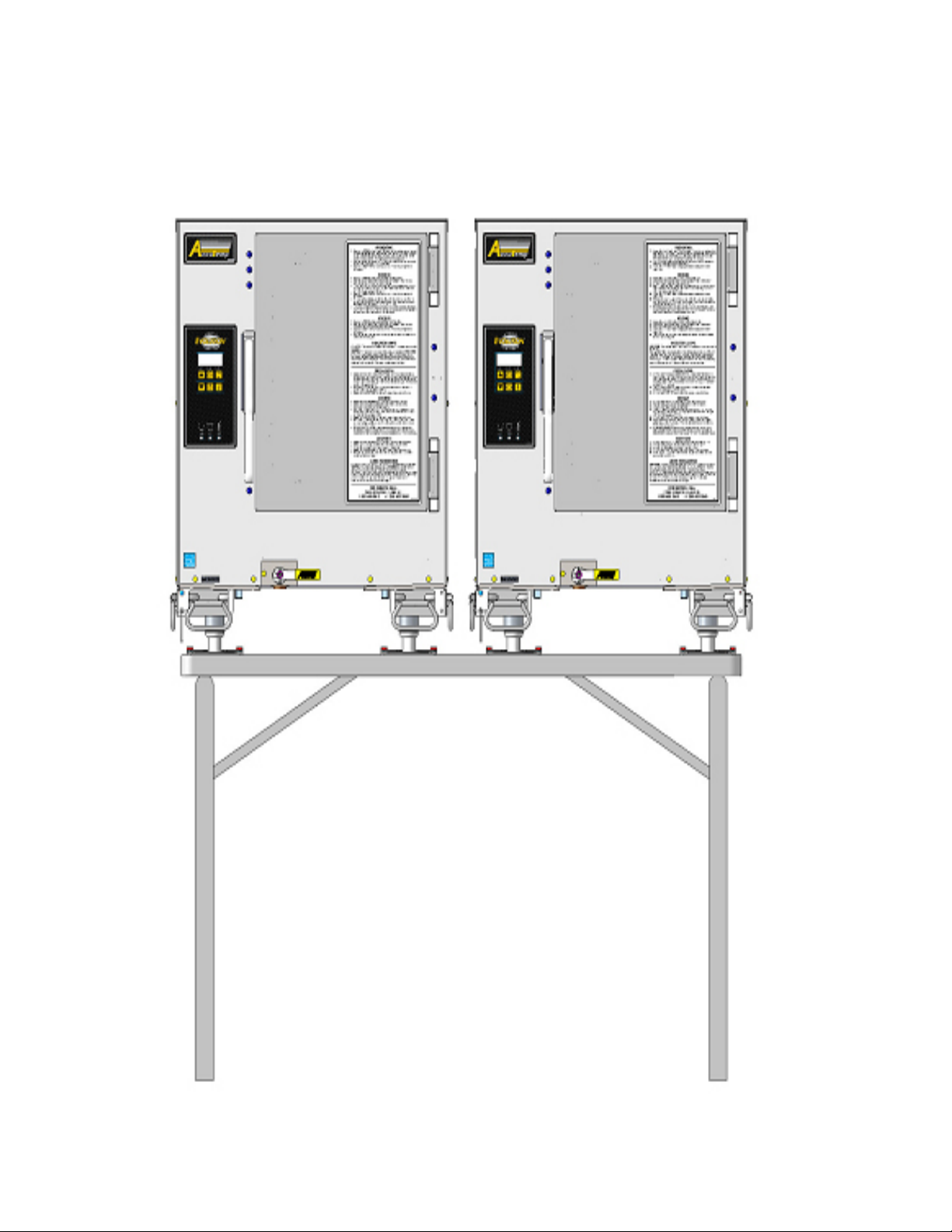
STEAMER TABLE ASSEMBLY
AT1A-3780-1 REV B
ITEM PART NUMBER DESCRIPTION
1 AT0H-3781-1 TABLE, ALUMINUM FOLDING
2 AT1M-3782-1 BRACKET, FLANGE MOUNTING
3 AT1M-3782-3 BRACKET, FLANGE MOUNTING
4 AT1M-3782-2 BRACKET, FLANGE MOUNTING
5 AT0F-2875-51081 SCREW, 1/4-20UNC X 1 HEX HEAD MACHINE
6 AT0F-1052-51000 WASHER 1/4 TYPE B PLAIN STAINLESS STEEL
7 AT0F-2691-51001 NUT, 1/4-20 NYLOC
SP8017-1404
EVOLUTION EEK STEAMER
PAGE 57
Page 59

INFORMATION
IMPORTANT SERVICE INFORMATION
AccuTemp Product, Inc. Technical & Customer Support Technician is
available Monday thru Sunday, 7:00am to 7:00pm EST.
800.480.0415 or 260.469.3040
• Phone - 800.480.0415 or 260.469.3040
• Email - service@accutemp.net
• Web site - www.accutemp.net
SP8017-1404
EVOLUTION EEK STEAMER
PAGE 58
Page 60

LIMITED WARRANTY
One Year– Parts and Labor
U.S. & Canada Only
AccuTemp Products, Inc. (AccuTemp) warrants that your AccuTemp equipment will be free of
defects in material and workmanship under normal use for a period of twelve (12) months from
installation or fteen (15) months from date of shipment from AccuTemp, whichever date rst
occurs (the Warranty Period). Registration of AccuTemp equipment is required at the time of
installation. Damage to AccuTemp equipment that occurs during shipment must be reported to
the carrier, and is not covered under this warranty. The reporting of any damage during shipment is
the sole responsibility of the commercial purchaser/user of such AccuTemp equipment.
AccuTemp provides an active service department, which should be contacted and advised of
service issues, regardless of the warranty period. During the warranty period, AccuTemp must be
contacted for warranty repairs and agrees to repair or replace, at its option, F.O.B. factory,
any part which proves to be defective due to defects in material or workmanship, provided
the equipment has not been altered in any way and has been properly installed, maintained, and
operated in accordance with the instructions in the AccuTemp Owners Manual. During the warranty
period, AccuTemp also agrees to pay for any factory authorized equipment service agency (within
the continental Applianceed States and Canada) for reasonable labor required to repair or replace,
at our option, F.O.B. factory, any part which proves to be defective due to defects
in materials or workmanship, provided the service agency has received advance approval from
AccuTemp factory service to perform the repair or replacement. This warranty includes travel time not
to exceed two hours and mileage not to exceed 50 miles (100 miles round trip), but does not include
post start-up assistance or training, tightening of loose ttings or external electrical connections, minor
adjustments, maintenance, or cleaning. AccuTemp will not reimburse the expense of labor required
to replace parts after the expiration of the warranty period.
Proper installation is the responsibility of the dealer, owner-user, or installing contractor and is
not covered by this warranty. Improper installation can affect your warranty. Installation is the
responsibility of the Dealer, Owner/User or the Installation Contractor. See the Installation
section of the Owners Manual. While AccuTemp products are built to comply with applicable
standards for manufacturers, including Underwriters Laboratories (UL) and National Sanitation
Foundation (NSF), it is the responsibility of the owner and the installer to comply with any
applicable local codes that may exist.
AccuTemp makes no other warranties or guarantees, whether expressed or implied, including
any warranties of performance, merchantability, or tness for any particular purpose. AccuTemp
liability on any claim of any kind, including negligence, with respect to the goods and services
covered hereunder, shall in no case exceed the price of the goods and services, or parts
thereof, which gives rise to the claim. In no event shall AccuTemp be liable for special,
incidental, or consequential damages, or damages in the nature of penalties.
This constitutes the entire warranty, which supersedes and excludes all other
warranties, whether written, oral, or implied.
SP8017-1404
EVOLUTION EEK STEAMER
PAGE 59
Page 61

 Loading...