


IS 3200

ES 2100 / ES 2200 / IS 3200 / BR 4200
User Manual
800-356-2671 | Accutech | www.accutech-ics.com
Version 2.4 June 2011
DOC.970002

ICS/ACCUTECH LIMITED WARRANTY
Innovative Control Systems, Inc. (ICS) warrants its Accutech™ equipment (Product) against defect in
materials and workmanship under normal use for one (1) year from the date of product shipment.
Defective equipment will be either repaired or replaced at ICS’ discretion, free of charge to the Customer
during the warranty period. ICS will supply labor depending on contract to repair or replace defective
equipment, free of charge, during the warranty period only if ICS or an ICS-certified subcontractor hired by
ICS installed such equipment.
In addition, ICS warrants its Accutech™ LC 1200 / ES 2200 / IS 3200 / BR 4200 System Tags against
defects in materials and workmanship under normal use and service for a period of one (1) year from the
date of shipment.
If a Tag fails during the warranty period due to defects in material and workmanship, ICS will at its sole
discretion, repair or replace the Tag with like quality product free of charge, although overnight shipping
charges may apply. Broken BR Tag clasps or broken LT/SB/CB Tag strap slots are not covered by
warranty.
Returned merchandise will only be accepted within 30 days of shipping
Authorization (RMA) number that is requested for full credit towards your account (less a 25% restocking
fee) if the product is returned unused, in its original packaging, and not damaged. No product will be
accepted for credit after 30 days from shipment date. All Tag sales are final
Furthermore, the express limited warranty of ICS shall be the sole and exclusive warranty of ICS, and ICS
hereby disclaims all other warranties, express, implied or statutory, including but not limited, all other
implied warranties of merchantability or fitness for a particular purpose. In no way should ICS be liable for
special, incidental, or consequential damages. ICS reserves the right to change such limited warranty from
time to time upon thirty (30) days written notice.
Computers and monitors provided by ICS shall not be submitted for repair to ICS but instead shall be
submitted directly to their respective manufacturer and serviced under their inherent manufacturer warranty
policy present at the time of purchase. Customer shall be responsible for registering any and all warranty
requirements.
ICS assumes no responsibility if any Product shall fail to function during any warranty period by reason of
any one or more of the following causes:
Abuse or misuse of the Product or failure to operate the Product in accordance with operating instructions or
specifications.
Improper preventive maintenance of the Product.
Alteration or modification of the Product not specifically approved in writing by ICS.
Improper installation, repair, modification, or servicing the Product performed by any unauthorized service
personnel.
Equipment or cabling damaged by unauthorized personnel knowingly or unknowingly.
Use or operation of the Product in conjunction with any accessories or auxiliary equipment not specifically
approved in writing by ICS.
Acts of God, including, but not limited to, natural disaster, fire, explosions, flood, accidents and the like.
24-hour, 7-days-a-week, 365-days-a-year over the phone technical support at 1-800-356-2671
with a valid Return Merchandise
.

User Manual Preface
Note: This equipment has been tested and found to comply with the limits for a Class B digital
device, pursuant to Part 15 of the FCC Rules. These limits are designed to provide reasonable
protection against harmful interference in a residential installation. This equipment generates, uses
and can radiate radio frequency energy and, if not installed and used in accordance with the
instructions, may cause harmful interference to radio communications. However, there is no
guarantee that interference will not occur in a particular installation. If this equipment does cause
harmful interference to radio or television reception, which can be determined by turning the
equipment off and on, the user is encouraged to try to correct the interference by one or more of
the following measures:
IMPORTANT FCC & DOC INFORMATION
Reorient or relocate the receiving antenna.
Increase the separation between the equipment and receiver.
Connect the equipment into an output on a circuit different from that to which the receiver is
connected.
Consult the dealer or an experienced radio/TV technician for help.
Canadian D.O.C. Statement
This digital apparatus does not exceed the Class B limits for radio noise emissions from digital appartus as set out in the radio
interference regulations of the Canadian Department of Communications.
Le present appareil numerique n,emet pas de bruits radiolectriques depassant les limits appliques aux appereils numeriques de Class B
prescrites dans le rglement sur le brouillage radiolectrique dicte par le ministere des Communications du Canada.
FCC ID/DOC for the ES Sensor:
FCC ID: JM7-IGWT-662002
Canada IC: 2683A-662002
This device complies with Part 15 of the FCC rules.
Operation is subject to the following two conditions:
(1) This device may not cause harmful interference,
and (2) this device must accept any interference
received, including interference that may cause
undesired operation.
FCC ID/DOC for the
Zone/Auxiliary Receiver:
FCC ID: JM7-IGWT-660076
Canada IC: 2683A-660076
This device complies with Part 15 of the FCC rules.
Operation is subject to the following two conditions:
(1) This device may not cause harmful interference,
and (2) this device must accept any interference
received, including interference that may cause
undesired operation.
FCC ID/DOC for the ES Controller:
FCC ID: JM7-ITYS-700035
Canada 2683 102 312
This device complies with Part 15 of the FCC rules.
Operation is subject to the following two conditions:
(1) This device may not cause harmful interference,
and (2) this device must accept any interference
received, including interference that may cause
undesired operation.
FCC ID/DOC for the S-TAD:
FCC ID: JM7-IGWT-662008
Canada IC: 2683A-662008
This device complies with Part 15 of the FCC rules.
Operation is subject to the following two conditions:
(1) This device may not cause harmful interference,
and (2) this device must accept any interference
received, including interference that may cause
undesired operation.
Preface User Manual
IMPORTANT:
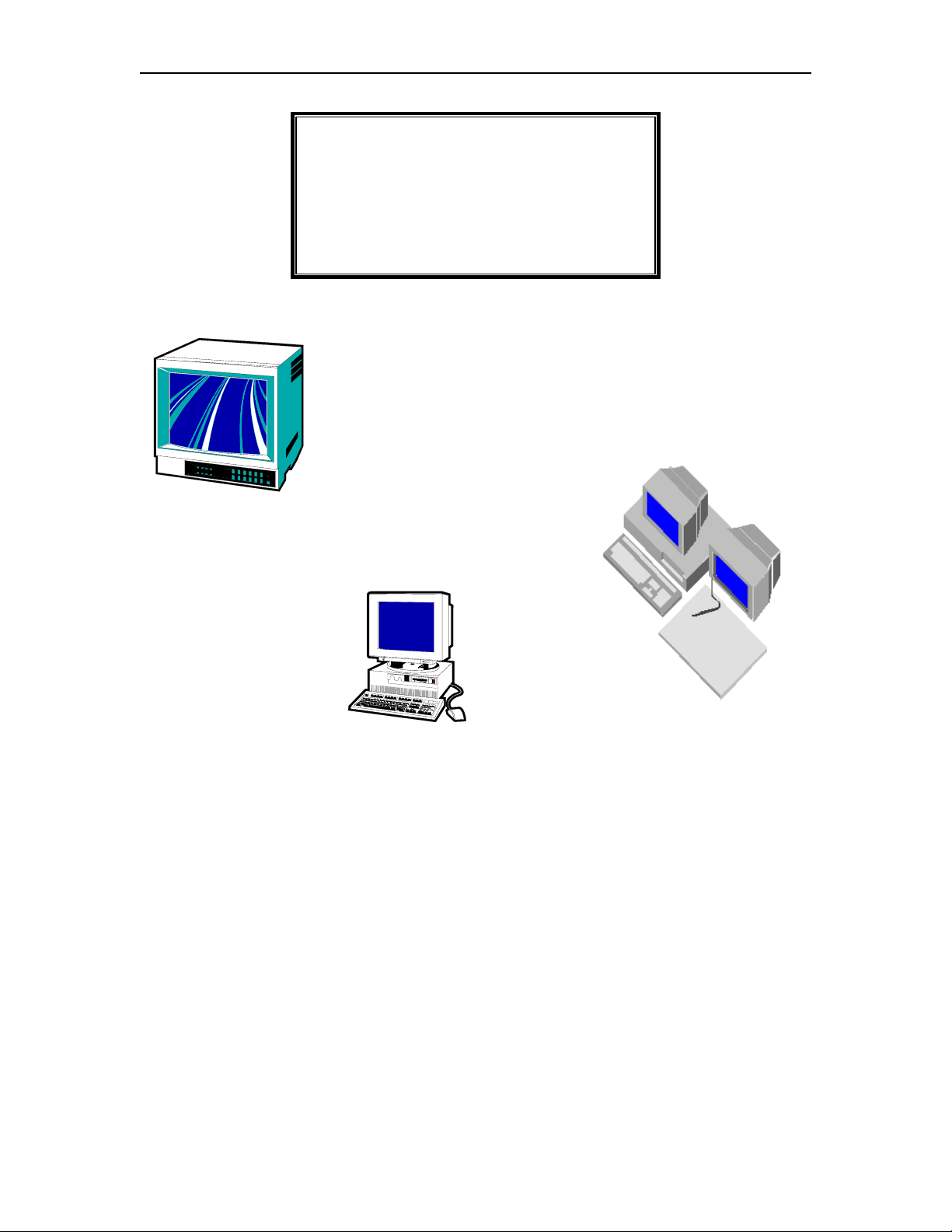
Keep all Televisions, Computers, X-ray
equipment, etc. at least 10 feet away from the ES
Receiver. This includes equipment located on the
other side of walls and doors.
Picture the area around the monitored zone as
a big globe with the receive antenna as the
center. Keep all sources of interference outside
this globe.
IMPORTANT NOTICE:
Do not store ES Sensor(s) within 3 feet of
ANY of the sources of electrical noise listed
on this page. These sources can reduce
sensor activation. This activation can lead
to possible undesirable responses from the
system.
Common Sources of Interference Include:
Television Sets
Computer Monitors
Medical Monitoring Equipment
Electric Motors
Electrical Distribution Panels and
Transformers
Fluorescent Lighting
Some Electronic Washers and Dryers
X-ray and other Imaging Equipment
Unshielded Computer Cables

Contents
Chapter 1: The Accutech Systems
ES 2200 System 1-1
IS 3200 System
BR 4200 System
Cut Band System 1-2
Alarms 1-3
How Accutech Systems Work
Addressing Alarms 1-4
Escorting 1-6
1-2
1-2
1-3
Chapter 2: System Components
Controller 2-2
Receiver 2-2
Keypad 2-2
Magnetic Switch 2-2
Passive Infrared Reader (PIR) 2-3
Tx Wand Antenna 2-3
Tri-Axis Antenna 2-3
ES 2200 System Tags 2-4
IS 3200 System Tags 2-4
BR 4200 System Tags 2-5
Cut Band System Tags 2-5
Secure Tag Activator/Deactivator (S-TAD) 2-6
PC 2-6
Tag Test Station (TTS) 2-7
Accutech Software 2-7
Multiplexer 2-7
Power Supply 2-7
Auxiliary Receiver (BR 4200 only) 2-7
Graphic Display Panel (GDP) 2-8
Staff Alert Panel (SAP) 2-8
Magnetic Locks 2-8
Elevator Deactivation Circuitry 2-9
Automatic Door Deactivation 2-9
Band Alarm Lockdown 2-9
Fire Panel Interface (FPI) 2-9
Local Alarm 2-9
Multi-Tone Local Alarm (MTLA) 2-10
Central Alarm 2-10
Speakers 2-10
Voice Alarm 2-10
Strobe Light 2-10
Push Button Override (PBO) 2-11
Timer 2-11
Chapter 3: Tags
ES 2200 System Tags 3-1
IS 3200 System Tags 3-1
BR 4200 System Tags 3-2
Cut Band System Tags 3-2
Tag Barcodes 3-3
Visual Pulse LED 3-3
LED Tag 3-4
Attaching Tags 3-6
Tag and Band Maintenance 3-10
Chapter 4: The S-TAD
Powering the S-TAD On/Off 4-1
Unlocking the S-TAD 4-1
Activating/Deactivating Tags 4-2
Programming Mode 4-3
Enable/Disable Band Alarm Sounder 4-3
Set Unlock Timeout 4-3
Summary of LEDs 4-4
Chapter 5: The Keypad
Keypad Operation 5-1
Initiating a Keypad Reset/Escort 5-1
Programming the master code 5-2
Programming user codes 5-3
Deleting user codes 5-3
Resetting the master code 5-4
Adjusting the Keypad Escort Time 5-4
Chapter 6: The Accutech Software
Overview
Configuration and System Type
Opening/Viewing multiple areas
The Environment
Passwords
Event Preferences
User Codes 6-13
Alarm events
Clearing Alarms 6-17
Suite Setup 6-18
Floor to Floor Tag Discrimination 6-19
Tag Control 6-19
Tag Test Station (TTS) 6-22
Tag Transfer 6-25
Reports
Software FAQ
Chapter 7: Facility Performance Testing
Testing Tags 7-1
Zone Functions Tested
Test Equipment Required
Zone, Lock Test
Zone, Egress Test (3000 and 3101 Locks) 7-3
Zone, Delayed Egress Test (3101)
Zone, Hallway Test
Zone, Elevator Deactivation Test
Door Ajar Test
Loiter Test
System Supervisor Test (Tx)
System Supervisor Test (Rx)
Fire Panel Interface (FPI) Test 7-7
Band Alarm Test (BR 4200 Systems only)
FAQ
Glossary
Index
6-1
6-2
6-2
6-5
6-8
6-10
6-15
6-28
6-33
7-1
7-1
7-2
7-3
7-4
7-5
7-5
7-6
7-7
7-7
7-8
F-1
G-1
I-1
800-356-2671 | Accutech | www.accutech-ics.com

User Manual
Chapter 1:
The Accutech Systems
IMPORTANT:
No Security System can replace human vigilance. Creating a safe environment requires the
combined efforts of nursing, physicians, security, and patients. Global policies, procedures,
and processes on patient care should be discussed and disseminated. Education,
communication, and coordination are key. No level of security can replace an informed and
knowledgeable staff. Any electronic or physical security system should be considered as a
supplemental deterrent, but by no means an end-all.


User Manual The Accutech Systems 1-1
The Accutech Systems
ES 2200 System
IS 3200 System
BR 4200 System
Cut Band System
Alarms
How Accutech Systems Work
Addressing Alarms
Escorting
Throughout this manual, when referring to the
various applications of the system, the term
“Tag” is used to represent all possible
applications of the system (i.e., a resident, a
patient, an infant, pediatrics, or an asset).
Furthermore, the terms “ingress” and “egress”
will be encountered. They are another way of
saying “coming and going” or “entering and
exiting” respectively.
The ES 2200 System is our platform system
from which all Accutech System’s are built.
Each subsequent system adds on to the system
before. Each system can be easily upgraded as
facility needs change and technology advances.
ES 2200 System
The function of the ES 2200 System is to alert
facility personnel of the possible egress of a
monitored resident.
The ES 2200 can be utilized for special care
residents suffering from wandering malady or
tendencies of straying into unauthorized areas or
leaving a facility, pediatric patients, asset
security, and/or infant security. The system is
designed so that each monitored zone is a stand-
alone system.
The ES 2200 System works with ES 2200
System Tags (
LT/SB22) and consists of:
a Controller
a Transmit Antenna*
a Receiver
a Magnetic Switch (
door zones) or
a Passive Infrared Reader (PIR)
(
hallway and elevators zones)
a Keypad
a Local Alarm*
* Multiple options are available for these
components. In most cases a Tx Wand Antenna is
used for the Transmit Antenna, however, in special
circumstances a variation of the Tx Wand antenna
can be used. Furthermore, there are various options
available for a Local Alarm.
When a Tag enters a monitored zone, the system
can automatically:
lock doors
deactivate elevators
sound alarms
flash strobe lights
trigger visual displays
(e.g., SAPs, GDPs, as well as PCs in IS
3200 and BR 4200 Systems)
The Controller can be mounted on the wall near
the point of egress or can be mounted out of
sight in an utility or equipment closet.
A Tx Wand Antenna is mounted on the wall at
the point of egress.
The Receiver is mounted internally (inside the
Controller) when the Controller is located at the
zone or externally (near the monitored zone)
when the Controller is located remotely.

1-2 The Accutech Systems User Manual
Virtually any hallway, doorway, stairwell, or
elevator can be made to sense a Tag and then
trigger audial and/or visual alarms to prompt a
staff response.
All cable used in Accutech Systems is plenum-
rated.
By adding options, most egress opportunities
can be eliminated without restricting staff,
visitors, and non-monitored residents movement.
Additional options that further enhance your
ability to prevent unescorted egress include:
Magnetic Lock(s)
Elevator Deactivation Unit(s)
Central Alarm
Door Ajar alarm
Loiter alarm
Staff Alert Panels (SAPs)
Graphic Displays Panels (GDPs)
Secure Tag Activator/Deactivator
(STAD)
STADs are capable of reading a Tag’s low
battery indicator and can assist in finding lost
Tags. However, ES 2200 Tags and/or VP
conversion Tags do not support the low battery
indicator.
IS 3200 System
The BR 4200 System is intended for infant
security.
The function of the BR 4200 System is to alert
facility personnel of the possible abduction of an
infant.
The BR 4200 System is the IS 3200 System
plus:
BR 4200 Auxiliary Receivers
(as needed)
The BR 4200 System uses BR 4200 System
BR42) that are placed on infants. In
Tags (
addition to the functionality of IS 3200 System
Tags, BR 4200 System Tags feature Intelli-Band
Technology, which will trigger alarms (audial
and/or visual) if the band is removed or
tampered with. Additional optional alarms (local
or central) can announce when a band alarm
incident has occurred.
Cut Band System
The function of the Cut Band System is to alert
facility personnel of the possible adduction of a
child. The Cut Band System is the BR 4200
System with Cut Band Tags, which will trigger
alarms (visual and/or audial) if the band is cut.
The IS 3200 System is the ES 2200 System plus:
a computer(s)
the Accutech Software
a Tag Test Station
a Multiplexer(s)
a Power Supply(s)
The IS 3200 System uses IS 3200 System Tags
LT/SB32) that are placed on the monitored
(
resident or asset. Once assigned, the computer
associates a name, room number, and any other
pertinent information about the resident/asset
with that Tag.
BR 4200 System

User Manual The Accutech Systems 1-3
Alarms
Egress
Door Ajar (Optional)
Loiter (Optional)
Supervisor
Band Alarm (BR 4200 systems only)
NOTE: In this manual, Egress alarms are
referred to as “Alarms.” Other alarm types are
referred to by name (i.e., Door Ajar, Loiter,
Supervisor, Band Alarm).
Egress
An alarm (i.e., an Egress alarm) occurs
whenever a Tag enters a monitored zone and the
door is opened or a PIR is tripped.
Door Ajar (Optional)
A Door Ajar alarm occurs when a door is open
for longer than the preset time (adjustable).
How Accutech Systems Work
Double-conditioning
Door zones
Elevator zones
Hallway zones
This section explains how Accutech Systems
react to a Tag entering a monitored door,
elevator, or hallway as well as alarm definitions.
Double conditioning
At most zones, two conditions are required to
generate an alarm. For example, at a door zone,
a Tag must be detected in the zone and the door
opened or, in hallway zones, a Tag must be
detected in the zone and PIR detection to
generate an alarm. Double conditioning (set
during installation) helps prevent nuisance
alarms.
Door zones
Loiter (Optional)
A Loiter alarm occurs when a Tag lingers in a
monitored zone for longer than the preset time
(adjustable).
Supervisor
A Supervisor alarm occurs when the
performance of the system has been altered due
to tampering or inadvertent acts such as cut
wires, antenna damage, or interference.
Band Alarm (BR 4200 systems only)
A Band Alarm occurs when a BR42 Tag band is
loosened, cut, saturated, removed, or tampered
with.
When a Tag enters a monitored door zone, the
system will detect the Tag. At that moment
(provided the door is closed, has a Magnetic
Lock(s), and the Lock is unobstructed) the
Magnetic Lock will energize, locking the door.
The Lock will remain locked for as long as the
Tag is in the monitored zone. When the Tag
leaves the monitored zone, the door will unlock
after an adjustable period of time (unless it is set
to latch when an alarm occurs).
Egress
If a Tag enters a monitored door zone with or
without a Magnetic Lock(s) and the door is
already open (or is opened while the Tag is in
the zone), the Accutech System will go into
alarm.

1-4 The Accutech Systems User Manual
Loiter
An optional Loiter function is available to alert
staff personnel if a Tag is lingering in a
monitored zone. The time setting is adjustable
(10-110 seconds) and is factory set for
approximately 15 seconds.
Door Ajar
An optional Door Ajar function is also available
to alert staff personnel if the door in a monitored
zone has been held open for too long. The time
range can be set for immediate or from 10 to 110
seconds and is factory set for approximately 15
seconds.
Elevator zones
Elevator Deactivation Circuitry restricts the
wearer of a Tag from using an elevator.
Egress
If a Tag enters a monitored elevator zone, the
elevator’s call button on that floor will be
deactivated (Call buttons on other floors are
unaffected and no one is restricted from coming
to the floor).
When a Tag is in the zone and the elevator doors
are closed, the doors will remained closed.
When a Tag is in the zone (or approaches the
zone) and the elevator doors are open, the doors
will remain open and an alarm will sound.
If the elevator car is en route to the floor when a
Tag approaches the zone, the elevator will arrive
on the floor, the door(s) will open, and the
system will alarm.
Hallway zones
Egress
If a Tag enters a monitored hallway zone, the
system will detect the Tag and the PIR will
detect motion. The system can then sound
alarms, trigger visual displays and, in special
circumstances, lock nearby doors.
Addressing Alarms
Addressing Egress alarms
Addressing Door Ajar alarms
Addressing Loiter alarms
Addressing Supervisor alarms
Addressing Band Alarms
(BR 4200 systems only)
NOTE:
Whenever an alarm occurs, always go to the
alarm location to address the alarm.
Addressing Egress alarms
An Egress alarm occurs whenever a Tag enters a
monitored zone and the door is opened or a PIR
is tripped.
When an Egress alarm occurs:
1. Go to the alarm location and take
appropriate action.
2. After taking appropriate action, you may
clear the alarm by entering a valid code
into the zone Keypad and, if necessary,
clear the alarm on the PC.

User Manual The Accutech Systems 1-5
Addressing Door Ajar alarms
A Door Ajar alarm occurs when a door is open
for longer than the preset allotted time.
When a Door Ajar alarm occurs:
1. Go to the alarm location and check to
see if the door is propped open or not
completely closed.
2. Close the door completely.
3. The system may automatically reset or,
if necessary, enter a valid code into the
zone Keypad and/or clear the alarm on
the PC.
Addressing Loiter alarms
A Loiter alarm occurs when a Tag lingers in a
monitored zone for longer than the preset
allotted time.
When a Loiter alarm occurs:
1. Go to the alarm location and check the
following:
a. If a person is loitering in that
zone’s Tx Activation Field?
b. Is a Tag from an adjacent room
being activated by this zone? If
so, call your service technician
for help in addressing this issue.
c. Is there is a misplaced Tag in
the zone?
2. After removing the cause, the system
may automatically reset or, if necessary,
enter a valid code into the Keypad
and/or clear the alarm on the PC.
to tampering or inadvertent acts such as cut
wires, antenna damage, or interference.
When a Supervisor alarm occurs:
1. Go to the alarm location and look for
visible damage to the Accutech
equipment.
2. Check for and remove any objects near
the zone equipment that may be causing
interference (metal carts, monitors or
other medical equipment as well as
personnel using wireless communication
devices).
3. If you locate and correct the cause, the
Supervisor alarm will cease. If
necessary, clear the alarm on the PC.
4. If not, call your service technician for
further assistance.
NOTE: Receiver-related supervise
events can be reset by the Keypad for
the duration of the supervise interval.
This will silence the alarm for up to 16
hours.
Addressing Band Alarms
(BR 4200 systems only)
A Band Alarm occurs when a BR42 Tag band is
loosened, cut, saturated, removed or tampered
with.
When a Band Alarm occurs:
1. Locate and assure the safety of the
infant.
Addressing Supervisor alarms
A Supervisor alarm occurs when the
performance of the system has been altered due

1-6 The Accutech Systems User Manual
2. After locating the infant, if you can find
no obvious reason for the alarm, check
the following:
a. Is the band snug around the
infant’s extremity and the
conductive fiber stripes are in
good contact with the infant’s
skin? If not, snug up the band.
b. Is excess band material properly
trimmed? If not, trim
appropriately.
c. Is the band wet? If so, replace
the band.
d. Is the Cam Lock completely
closed? If not, snap it closed.
3. After verifying the above, enter a valid
code into any Keypad and, if necessary,
clear the alarm on the PC.
Escorting
DISCLAIMER:
The following instructions are intended as a
guidance document only. Each facility should
review these recommendations and modify as
necessary to meet their own unique security
requirements.
To escort Tags through a monitored zone, use
the following instructions:
1. Enter a valid code into the zone’s
Keypad. This will invoke the Keypad’s
Escort function. The Keypad’s Escort
function will allow the Tag to pass
through the monitored zone for the
designated Escort time. The duration of
the Escort function is adjustable from 0
to 98 seconds (
factory set at 15 seconds).
2. Escort the Tag through the zone.
NOTE: For slower moving residents,
you may have to invoke the Escort
function again. However, if this is the
case, an alarm may sound. Therefore,
take into consideration the Escort time
duration at that zone. If the door handles
slow moving residents often, consider
extending the Escort time or using a
wheelchair to escort residents.
3. To prevent tailgating, once you are
through the zone wait until the escort
time has timed-out before proceeding
(the green LED will extinguish).
NOTICE:
While escorting Tags, be aware of “tailgating.”
Tailgating is the practice of Tags lingering near
a monitored zone (usually an exit point) until an
authorized escort passes through the zone then
immediately following behind through the zone.
To prevent tailgating, be aware of all traffic near
a monitored zone and once you are through the
monitored zone wait until the escort time has
timed-out before proceeding.

User Manual
Chapter 2:
System Components


User Manual System Components 2-1
System Components
This section contains a brief description and a
simple graphic (not to scale) for each component
and its role in the Accutech System.
NOTE: Accutech reserves the right to substitute
comparable components.
Since each facility’s system is unique to its
particular needs, check off the components that
your system has.
ALL SYSTEMS COMPONENTS:
Controller
Receiver
Keypad
Magnetic Switch (with Door zones)
Passive Infrared Reader (PIR)
(with Elevator and Hallway zones)
TRANSMIT ANTENNA:
Tx Wand Antenna
Tri-Axis Antenna
TAGS:
ES 2200 System Tags (LT/SB22)
IS 3200 System Tags (LT/SB32)
BR 4200 System Tags (BR42)
Cut Band Tags
TESTERS:
Secure Tag Activator/Deactivator (S-TAD)
Tag Activator/Deactivator (TAD)
IS 3200 and BR 4200 COMPONENTS:
PC
Tag Test Station (TTS)
Accutech Software
Multiplexer
Power Supply
Auxiliary Receivers (BR 4200 only)
ALERT PANELS:
Graphic Display Panel (GDP)
Staff Alert Panel (SAP)
RESTRAINTS:
Magnetic Lock, 3000 Series
Magnetic Lock, 3101 Series
(Delayed Egress)
Elevator Deactivation
Automatic Door Deactivation
Band Alarm Lockdown
Fire Panel Interface (FPI)
(required for systems with Magnetic Locks
and/or Elevator Deactivation)
ALARMS:
Local Alarm
Multi-Tone Local Alarm
Central Alarm
Speakers
Voice Alarm
Strobe Light
ADDITIONAL OPTIONS:
Push Button Override (PBO)
Timer
2-2 System Components User Manual
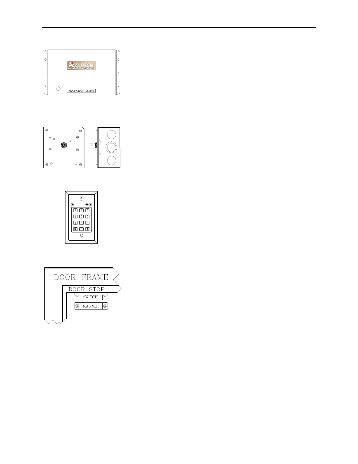
Controller
Figure 2.1 The Controller
Figure 2.2 Receiver
The Controller (
Figure 2.1) coordinates and controls all of the devices
and functions of the Accutech Security System.
Receiver
The Receiver (
Figure 2.2) picks up the signal from an activated Tag
and relays it to the Controller and the Multiplexer. Receivers can be
internally or remotely mounted near a monitored zone.
Keypad
The Keypad (
Figure 2.3) is used to escort residents or infants through a
monitored zone and to reset zone equipment once an alarm has
occurred.
Figure 2.3 Keypad
Figure 2.4 Magnetic Switch
Magnetic Switch
The Magnetic Switch (
Figure 2.4) is used on a door when alarm
activation is not desired unless the door is opened.
User Manual System Components 2-3
Passive Infrared Reader (PIR)
Figure 2.5
Passive Infrared Reader (PIR)
Figure 2.6
Tx Wand Antenna
A Passive Infrared Reader (PIR) (
Figure 2.5) is a device that uses a
infrared sensor to monitor doors, hallways, corridors, and
passageways.
Like the Magnetic Switch, the PIR is used in areas where alarm
activation is not desired immediately upon Tag detection. It can also
be used in hallways or other areas where a Magnetic Switch would not
be feasible.
Tx Wand Antenna
The Tx Wand Antenna (
Figure 2.6) generates a Tag-activating signal
near a monitored zone. This signal is referred to as the “Tx Activation
Field.”
Figure 2.7
Tri-Axis Antenna
Tri-Axis Antenna
The Tri-Axis Antenna (
antenna.
Figure 2.7) is a variation of the Tx Wand
2-4 System Components User Manual
ES 2200 System Tags
LT22
or
SB22
Figure 2.8
ES 2200 System Tag
(band not shown)
The ES 2200 System Tag (
Figure 2.8) is a small wristwatch-sized
device that is worn by a resident or attached to an asset.
Two models are available:
LT = Long Term resident care
SB = Slotted Back; to be used on infants and assets
When the Tag enters a monitored zone, the system detects the Tag and
responds by sending a signal via the Receiver to the Controller. This
information is processed by the Controller for appropriate control
action or response at the zone.
Tags are attached to residents/assets with a nylon-mesh-reinforced
vinyl band.
IS 3200 System Tags
LT32
or
SB32
Figure 2.9
IS 3200 System Tag
(band not shown)
In addition to the look and functionality of ES 2200 System Tags, IS
3200 System Tags (
Figure 2.9) are assigned to a specific resident or
asset (via the Tag Test Station and a computer with the Accutech
Software). The computer then associates a name, room number, and
any other helpful comments about the resident or asset with that Tag.
When the Tag enters a monitored zone, the system detects the Tag and
responds by sending a signal via the Receiver to the Controller and the
Multiplexer. This information is processed by the Controller for
appropriate control action or response at the zone while the
Multiplexer sends the information to a computer with the Accutech
Software and/or to Graphic Display Panels (GDPs). This information
is processed by the Controller and the Multiplexer for appropriate
control action or response at the zone.
Tags are attached to residents/assets with a nylon-mesh-reinforced
vinyl band.
User Manual System Components 2-5
BR 4200 System Tags
In addition to the functionality of an IS 3200 System Tag, the BR 4200
System Tag (
saturated, removed or tampered with.
Figure 2.10) will alarm if the band is loosened, cut,
BR 4200 System Tags are attached to infants with a conductive-fiberstriped cloth band.
BR42
Figure 2.10
BR 4200 System Tag
(band not shown)
Figure 2.11
Cut Band Tag
Cut Band Tag
Similar to the functionality of a BR 4200 System Tag, Cut Band Tags
(
Figure 2.11) will alarm if the band is cut and is designed for use in
pediatrics applications.
Cut Band Tags are attached to patients with a band (
plastic covers (
Figure 2.14), are activated/deactivated using an
Figure 2.13) and
S-TAD unit, and contain a visual pulse LED. Using plastic covers with
a Cut Band Tag will significantly reduce the need for sanitizing the
Tag between applications.
Figure 2.13 Cut Band band Figure 2.14 Plastic Covers
2-6 System Components User Manual
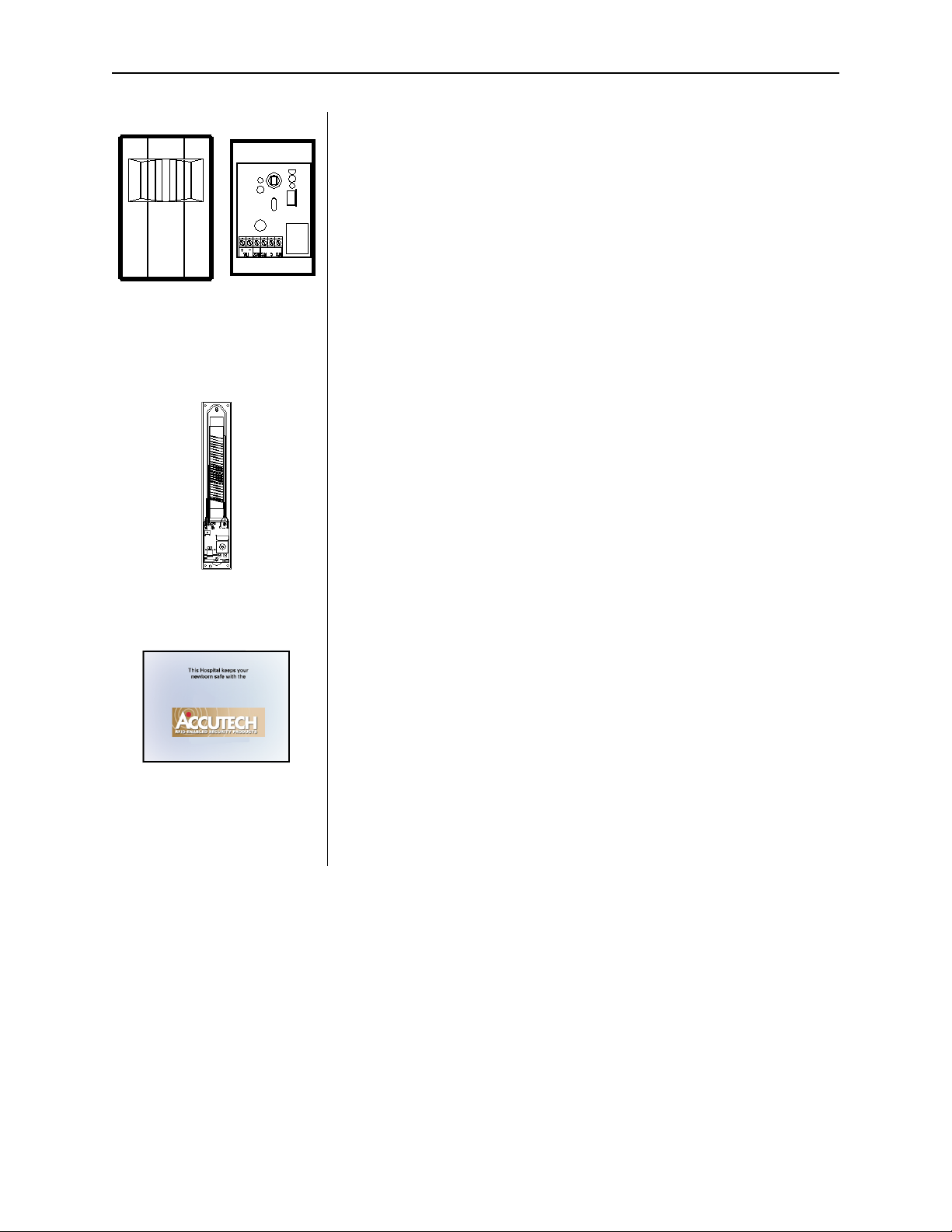
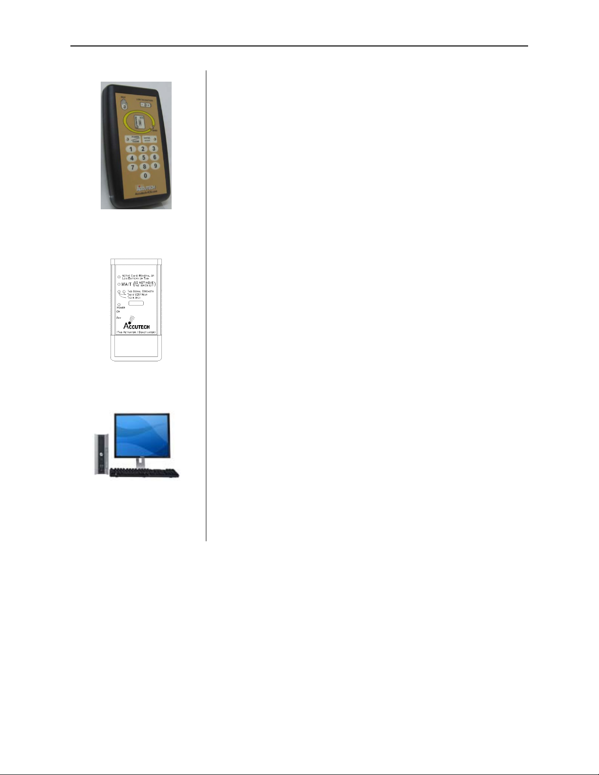
Secure Tag Activator/Deactivator (S-TAD)
The S-TAD (Secure Tag Activator/Deactivator) is used to check the
functionality of an Accutech Tag. Accutech Tags operate by internal
battery. Over the course of normal operation, Tags eventually lose
battery power and the Tags will need to be replaced. The S-TAD is
used to determine if a Tag has sufficient battery power to respond to
an activating signal.
Figure 2.15
S-TAD
Tag Activator/Deactivator (TAD)
TAD (Tag Activator/Deactivator) is used to check the functionality of
an Accutech Tag. Accutech Tags operate by internal battery. Over the
course of normal operation, Tags eventually lose battery power and the
Tags will need to be replaced. The TAD is used to determine if a Tag
has sufficient battery power to respond to an activating signal. The
TAD was replaced by the S-TAD in late 2008.
Figure 2.16
The TAD
Figure 2.17 PC
PC
A PC (
Figure 2.17) is required for IS 3200 and BR 4200 Systems.
The Accutech Software is installed on each monitoring PC and is used
to display incoming event information. Using the facility’s floor plan
as the background, zone-specific icons (i.e., doors, elevators,
stairwells, hallways, and BR 4200 Auxiliary Receivers) are placed at
each monitored zone’s location and become animated when an alarm
occurs.
User Manual System Components 2-7
Tag Test Station (TTS)
Figure 2.18 Tag Test Station
Figure 2.19
Accutech Software example
Figure 2.20 Multiplexer
The Tag Test Station (TTS) (
Figure 2.18) is used for Tag
assignments, checking for low Tag battery, and verifying the Tag
number.
Accutech Software
The Accutech Software (
Figure 2.19) is installed on each
monitoring PC and is used to display incoming event information.
Using the facility’s floor plan as the background, zone-specific
icons (i.e., doors, elevators, stairwells, hallways, and BR 4200
Auxiliary Receivers) are placed at each monitored zone’s location
and become animated when an alarm occurs.
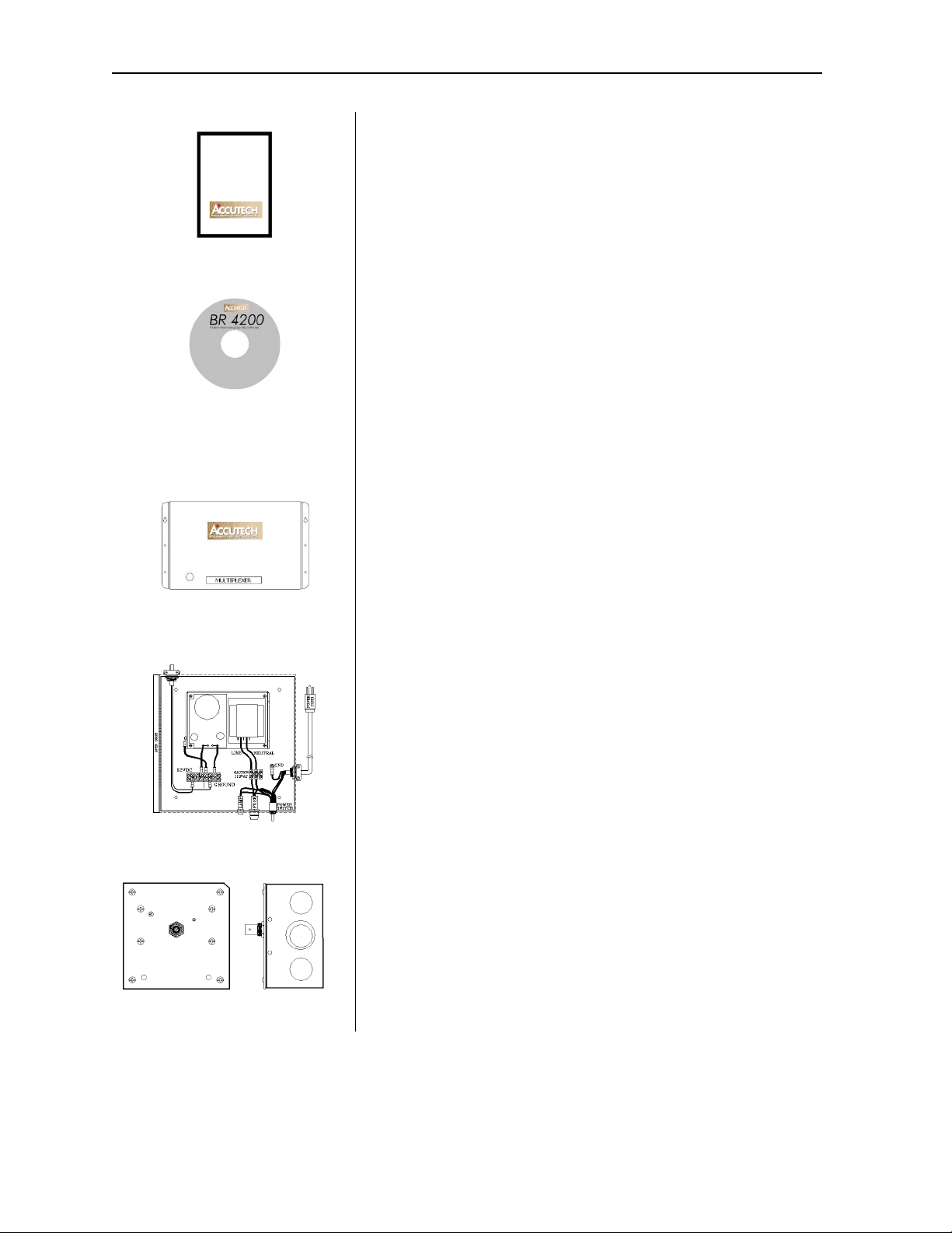
Multiplexer
The Multiplexer (
Figure 2.20) relays event information sent from
the Controller and Receivers to Graphic Display Panels (GDPs)
and to PCs with the Accutech Software.
Figure 2.21 Power Supply
Figure 2.22 Auxiliary Receiver
Power Supply
The inclusion of multiple peripherals into the Accutech System
may require more power than the Controller can provide. In these
cases, a Power Supply (
Figure 2.21) is added to the system to meet
the additional power requirements.
Auxiliary Receiver
The Auxiliary Receiver (
Figure 2.22) picks up the signal from an
activated Tag and relays it to the Controller and the Multiplexer.
2-8 System Components User Manual
Graphic Display Panel (GDP)
Figure 2.23
Graphic Display Panel (GDP)
Figure 2.24
Staff Alert Panel (SAP)
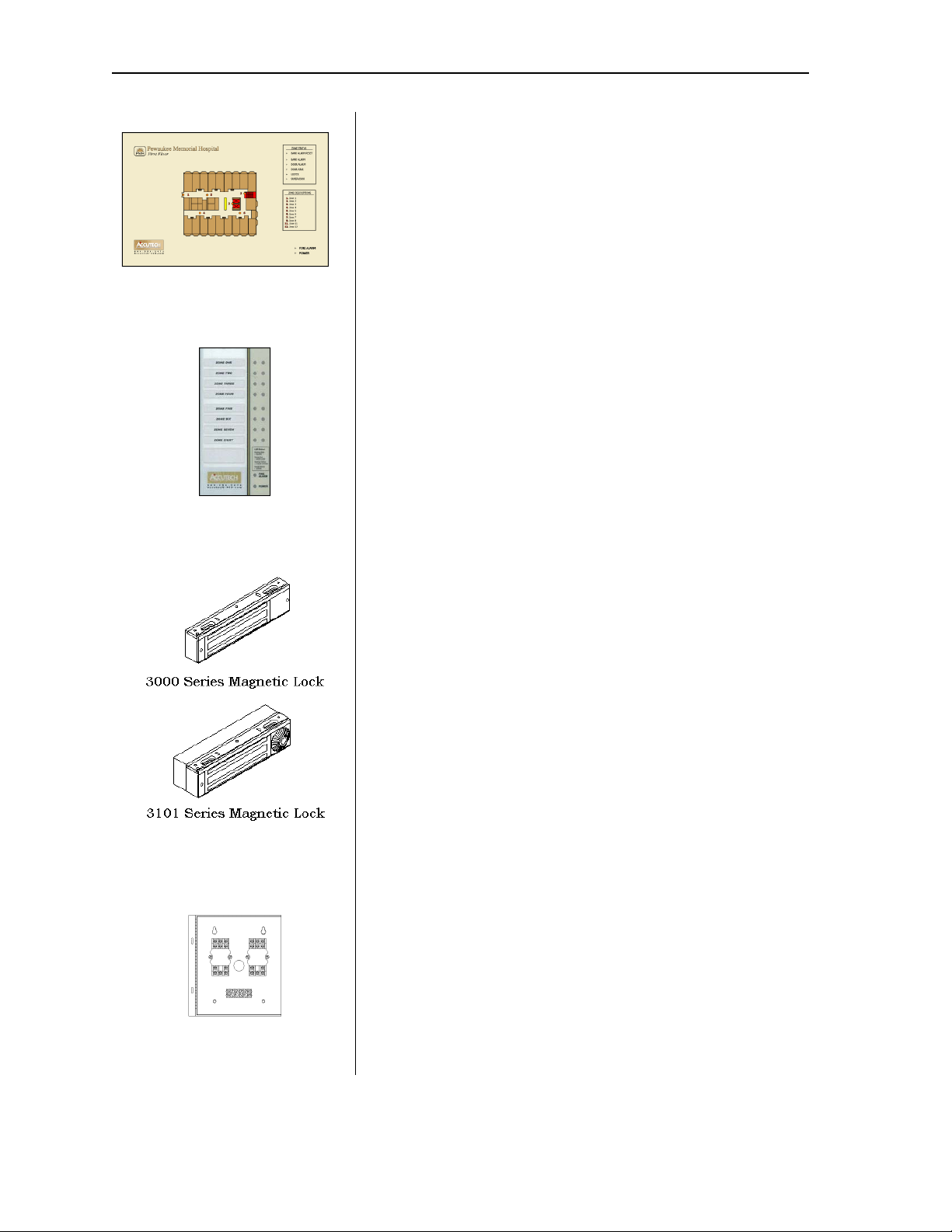
The Graphic Display Panel (GDP) (
Figure 2.23) provides the staff
with a visual representation of the floor being monitored. GDPs
are custom-made to a facility’s floor plan and notify staff when
an alarm or event occurs in a monitored zone through a piezo
buzzer and alarm-specific LEDs.
Staff Alert Panel (SAP)
The Staff Alert Panel (SAP) (
Figure 2.24) notifies staff when an
alarm condition occurs in a monitored zone through a piezo
buzzer and alarm-specific LEDs.
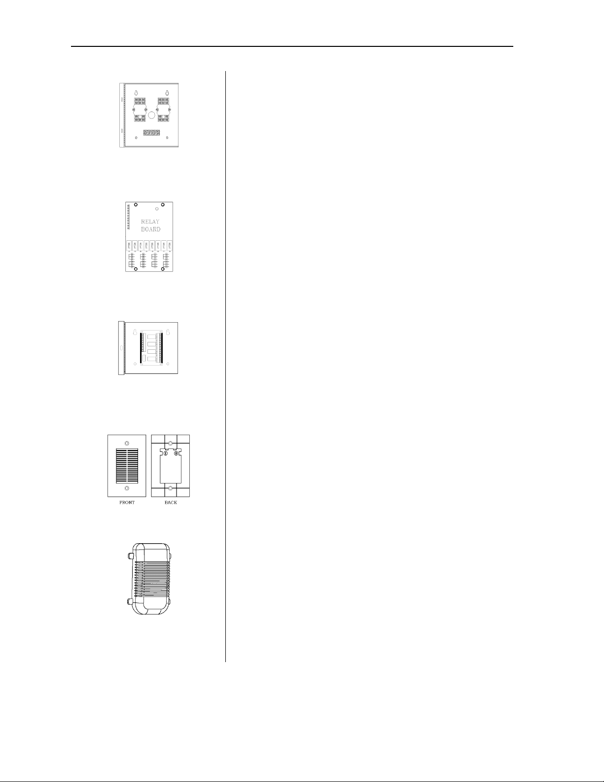
Magnetic Locks
Magnetic Locks (
Figure 2.25) prevent unescorted egress.
Figure 2.25 Magnetic Locks
Figure 2.26 Elevator Deactivation
Circuitry
The 3000 Series Magnetic Lock features:
1500-pound holding force
12V to 24V AC/DC
Unlocks instantly if the facility’s fire panel is activated
The 3101 Series Magnetic Lock features:
1200-pound holding force
12V AC/DC
Unlocks instantly if the facility’s fire panel is activated
NFPA101 Life Safety Code conformity (Delay Egress Circuitry)
a selectable nuisance delay
an Accutech-exclusive electromagnetic coil
an Accutech-exclusive firmware chip
Elevator Deactivation Circuitry
Elevator Deactivation Circuitry (Figure 2.26) is designed to
prevent someone (or an asset) wearing an Accutech tag from
using an elevator to leave a monitored floor. Using Relays
enclosed in the Elevator Deactivation Relay Cabinet, the Elevator
Company is able to interface with the Accutech System.
User Manual System Components 2-9
Automatic Door Deactivation
In automatic door applications (doors that open via a motion
Figure 2.27), the Accutech System can
Figure 2.27
Automatic Door Deactivation
sensor or push paddle) (
deactivate this feature when a Tag enters a monitored zone’s Tx
Activation Field.
Band Alarm Lockdown
Figure 2.28
Band Alarm Lockdown
Figure 2.29
Fire Panel Interface (FPI)
Band Alarm Lockdown (
Figure 2.28) can engage specific facility
Magnetic Locks when a Band Alarm occurs.
Fire Panel Interface (FPI)
The Fire Panel Interface (FPI) (
Figure 2.29) ensures that in the
event of a fire alarm, the Magnetic Locks and Elevator
Deactivation Circuitry will disengage. Although the restraint
systems are disengaged, the system’s visual and audial alarms
will remain active.
Local Alarm
The Local Alarm (
Figure 2.30), a sounder, is intended to attract
attention near the monitored zone.
Figure 2.30 Local Alarm
Figure 2.31
Multi-Tone Local Alarm
Multi-Tone Local Alarm (MTLA)
The Multi-Tone Local Alarm (MTLA) (
Figure 2.31) can use 8
tone variations to attract attention near the monitored zone.

2-10 System Components User Manual
Central Alarm
Figure 2.32 Central Alarm
Figure 2.33 Speakers
Figure 2.34 Voice Alarm
The Central Alarm (
a tone generator that drives Speakers (
a facility. There are eight different tones available. You may
Figure 2.32) is a multi-tone alert. It consists of
up to 5) located throughout
choose to assign a separate tone for each zone, share the same
tone for adjacent zones, or use one tone for all zones.
Speakers
The 8-ohm Speakers (
Figure 2.33) provided by Accutech are used
in conjunction with the Central Alarm.
Voice Alarm
The Voice Alarm (
Figure 2.34), located at a monitored zone, will
repeat a recorded message (up to 20 seconds) continuously when
an alarm occurs.
Strobe Light
A Strobe Light (
Figure 2.35) can be used as another alarm
notification device.
Figure 2.35 Strobe Light
Figure 2.36
Push Button Override (PBO)
Figure 2.37 Timer example
Push Button Override (PBO)
The Push Button Override (PBO) (
Figure 2.36) triggers the
Keypad’s Escort function; this option allows free access through
a monitored door from the non-Keypad side of the door.
Timer
A Timer (
Figure 2.37) allows the user to engage or disengage
certain system functions on a time schedule.

User Manual
Chapter 3:
Tags

User Manual Tags 3-1
Tags
ES 2200 System Tags
IS 3200 System Tags
BR 4200 System Tags
Cut Band Tags
Tag barcodes
Visual Pulse LED
Tag base color chart
LED Tag
Attaching Tags
Tag and Band Maintenance
Note: The Tag Model CB’s Pod (plastic
covers) has not been evaluated by UL.
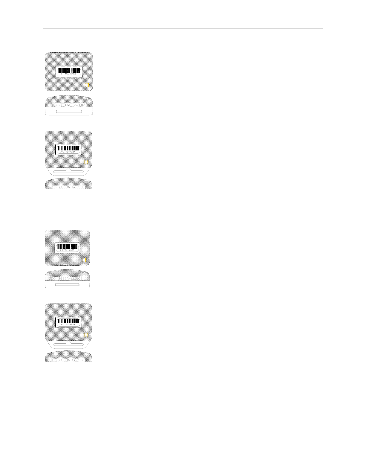
ES 2200 System Tags
ES 2200 System Tags (Figure 3.1 and 3.2) are
small wristwatch-sized devices worn by a
resident or attached to an asset. When a
resident or patient enters a Tx Activation
Field, the Tag sends a signal to the zone
Controller, via the Receiver. The zone
Controller processes this information for
appropriate control action or response (such
as sounding alarms, locking doors, and/or
deactivating elevators).
IS 3200 System Tags
In addition to the functionality of an ES
2200 System Tag, IS 3200 System Tags
Figure 3.1 and 3.2) are preprogrammed with
(
a number and assigned to a specific resident
or asset (via the Tag Test Station and
Accutech Software). Once assigned, the
computer associates a name, room number
and any other pertinent information about
the resident/asset with that Tag number.
IS 3200 System Tags also contain a visual
pulse LED. Tags are activated/deactivated
with an S-TAD unit. Available in SB
(slotted back) or LT (long term) tag case
styles.
ES System 2200 Tags also contain a visual
pulse LED. Tags are activated/deactivated
with an S-TAD unit. Available in SB
(slotted back) or LT (long term) tag case
styles.
The ES 2200 System Tag band is made of
nylon-reinforced vinyl with nylon mesh. The
band is designed to resist tearing caused by
pulling or chewing on the band. However, if
the band becomes frayed or torn it will need
to be replaced. In long-term applications, the
band should be replaced periodically for
cleanliness.
Figure 3.1 SB Tag case style
Figure 3.2 LT Tag case style
3-2 Tags User Manual
BR 4200 System Tags
In addition to the functionality of an IS 3200
System Tag, BR 4200 System Tags (
) will alarm if the band is removed or
3.3
tampered with in any way.
BR 4200 System Tags also contain a visual
pulse LED. Tags are activated/deactivated
with an S-TAD unit.
BR 4200 System Tags are attached to
infants with a conductive-fiber-striped cloth
band.
Figure
Figure 3.4 Cut Band Tag
Figure 3.3 BR 4200 System Tag
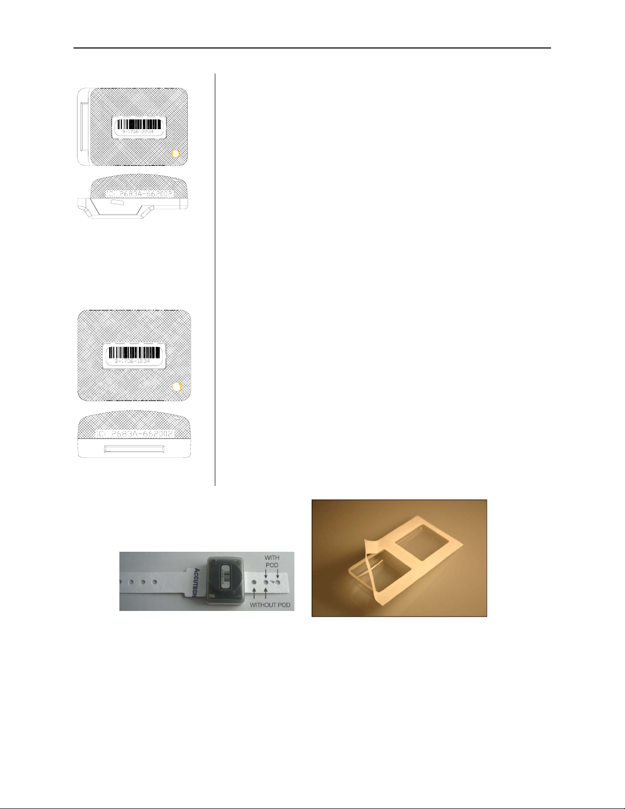
Cut Band Tags
Similar to the functionality of a BR 4200
System Tag, Cut Band Tags (
alarm if the band is cut, removed, or
tampered with in any way and is designed
for use in pediatric applications. Cut Band
Tags also contain a visual pulse LED.
The band (Figure 3.5) accommodates
various wrist/ankle lengths.
Figure 3.4) will
Figure 3.5 Cut Band Band
Figure 3.6 Cut Band Pod
Using a pod (Figure 3.6) with a Cut Band
Tag will significantly reduce the need for
sanitizing the Tag between applications and
is water-resistant during use.
 Loading...