

Page 1

ExaSAN SWF16
User Guide
Includes hardware setup information for:
• PCIe 2.0 switch (Model: SWF16)
• PCIe 2.0 RAID System (Models:A12S2-PS; B08S2-PS))
• QSFP HBA (Model: ACS-63200NT(Z1M))
• QSFP PCIe Cables
Also includes software setup information for:
• Switch management software: Switch Web GUI
• SAN management software: SANit
Accusys, Inc.,
January 10, 2013
Version: V1.0
Page 2

Release
No.
Date
Revision Description
V1.0
01/10/2013
Initial re lease on CD.
Revision Sheet
Revision Sheet
Page i
User Guide
Page 3

Caution
the safety instruction i s no t o bser v ed.
PREFACE
PREFACE
Notice
The product features and specifications described in this guide are subject to change
without notice.
The manufacturer shall not be liable for any damage, or the loss of information resul ting
from the performance or use of the information contained herein.
About This Guide
Congratulations on your purchase of the ExaSAN (pronounced X-sa-SAN) switch
“SWF16”, a revolutionary high bandwidth PCIexpress based SAN switch, specifically
developed for post production environments. It delivers stability, exceptional
performance, and scalable capacity at a very affo rd able cost.
This guide also contains instructions for installing and using the ExaSAN PCIe switch, RAID
(Redundant Array of Independent Disks) technologies, SANit (SAN management
software) and RA IDGuard X (ExaSAN’s RA ID man agement software) .
If you are new to ExaS AN switch, RAID, S ANi t and R AIDGuard X, thi s guide wi ll help you
become familiar with these technologies, and assist you in setting up and using ExaSAN
storage with the SWF16. If you are already familiar with these technologies, use this
guide as a reference for implementing your ExaSAN SAN solution to achieve maximum
performance and rel ia bility.
For details of hardware installation, setup, configuration and cons ide rat ions, see
• Chapter 1, “Introduc ing ExaSAN PCIe2.0 Swit ch SWF16”
• Chapter 2, “Preparing t o set up an ExaSAN SAN environment”
• Chapter 3, “Installing E x aSAN SAN environment”
• Chapter 4, “Using Switch Web GUI & SANit”
• Chapter 5, “RAID Over view”
• Chapter 6, “Appendix”
Guide to Conventions
Inside the double box es is the important info rmation that users shou l d be aw are of:
This indicates the exist en c e o f a po t en tial hazard that could result
in personal injury, damage to your equipment or loss of data if
User Guide Page ii
Page 4

Note
ExaSAN RAID system.
PREFACE
This indicates useful tips on getting the most from your Accusys
Trademarks
Accusys and the names of Accusys products and logos referenced herein are
trademarks and/or service marks or registered trademarks and/or service marks of
Accusys, Inc.
Xsan, Mac, Mac OS, and Macintosh are either registered trademarks or trademarks of
Apple. Other product and company names mentioned herein may be trademarks
and/or service marks o f t heir r espective owners.
All contents of this manual are copyrighted by Accusys, Inc.
The information contained herein is the exclusive property of Accusys, Inc. and shall not
be copied, transferred, photocopied, translated on paper, film, electronic media, or
computer-readable form, or otherwise reproduced in any way, without the express
written permission of Accusys Inc.
Document version 1.0
Date Published: January, 2013
© Copyright 2012 Accusys, Inc.
All Rights Reserved.
This device complies with Part 15 of the FCC Rules. Operation is subject to the following
two conditions: (1) this device may not cause harmful interference, and
(2) this device must accept any interference received, including interference that may
cause undesired operation.
User Guide Page iii
Page 5

TABLE OF CONTENTS
ExaSAN SWF16 User Guide
TABLE OF CONTENTS
Page #
Notice ..................................................................................................................................................... ii
About This Guide
Guide to Conventions
Trademarks
1. Introducing ExaSA N P CIe2.0 switch ............................................................................. 1-1
System Overview ................................................................................................... 1-1
1.1
1.1.1 What is the ExaSAN Solution .................................................................................................. 1-1
What is the ExaSAN Switch SWF16 ........................................................................................ 1-3
1.1.2
ExaSAN SAN environment Components and Accessories .............................................. 1-3
1.1.3
1.1.3.1
1.1.3.2
1.1.3.3
1.1.3.4
1.1.3.5
1.1.4
ExaSAN PC Ie 2.0 SAN switch – SWF16 ......................................................................... 1-3
ExaSAN PCIe 2.0 Storages ............................................................................................. 1-3
ExaSAN QSFP Host Bus Adapter (ACS-63200NT) ....................................................... 1-4
QSFP (Quad Small Form-factor Pluggable) PCIe Copper or Optical Cables .... 1-4
Power Cord & Power convertors ................................................................................. 1-5
Key Features of SWF16 ............................................................................................................ 1-5
................................................................................................................................... ii
.......................................................................................................................... ii
........................................................................................................................................... iii
1.2 Unpacking the System .......................................................................................... 1-6
1.2.1 What Is In Your Order .............................................................................................................. 1-7
Checking the Equipment you’ll need ................................................................................. 1-7
1.2.2
Unpacking ................................................................................................................................. 1-7
1.2.3
1.3 What’s in the Box ................................................................................................... 1-8
1.3.1 SWF16 System ........................................................................................................................... 1-8
SWF16 Accessories .................................................................................................................. 1-8
1.3.2
MDC package ......................................................................................................................... 1-8
1.3.3
1.4 Your SWF16 at a Glance ....................................................................................... 1-9
1.4.1 ExaSAN SWF16 .......................................................................................................................... 1-9
1.4.1.1
1.4.1.2
1.4.1.3
1.4.1.4
1.4.2
SWF16 Front Panel & LED Indicators ............................................................................ 1-9
Beeper Codes ...............................................................................................................1-10
Mirror device Indicators ..............................................................................................1-11
SWF16 Rear Panel .........................................................................................................1-12
ExaSAN QSFP Host Bus Adapter (HBA) and LED Indicators ...........................................1-15
1.5 What Else You Need ............................................................................................ 1-17
Preparing to Install ExaSAN SWF16 .............................................................................. 2-1
2.
Precaution for Handling the System ..................................................................... 2-1
2.1
Choosing the Location for the System ................................................................. 2-1
2.2
Electrical Power ..................................................................................................... 2-1
2.3
Operating Environment ......................................................................................... 2-2
2.4
Security ................................................................................................................... 2-2
2.5
User Guide Page iv
Page 6

TABLE OF CONTENTS
3. Installing the ExaSAN SWF16 ......................................................................................... 3-1
Hardware installation ............................................................................................ 3-1
3.1
3.1.1 Installing the HBA Card ........................................................................................................... 3-1
Connecting SWF16 to the ExaSAN storages ....................................................................... 3-3
3.1.2
Connecting SWF16 to the Host systems .............................................................................. 3-4
3.1.3
Connecting the switch LAN and power cord ................................................................... 3-5
3.1.4
3.2 Powering the System On and Off ......................................................................... 3-6
3.2.1 Powering On ............................................................................................................................. 3-6
Powering Off ............................................................................................................................. 3-7
3.2.2
3.3 Installing the Installer Package ............................................................................ 3-7
3.3.1 Before You Start ....................................................................................................................... 3-7
Installing the installer package ............................................................................................. 3-8
3.3.2
3.3.2.1
3.3.2.2
3.3.3
3.3.3.1
3.3.3.2
3.3.4
Installing on MAC and Windows .................................................................................. 3-8
Installing on Linux ..........................................................................................................3-11
Confirm the ExaSAN RAID system driver on OS ...............................................................3-13
Confirming the ExaSAN RAID system driver on Mac .............................................3-13
Confirming the ExaSAN RAID system driver in Windows .......................................3-15
Confirm LEDs on HBA ............................................................................................................3-16
4. Using Switch Web GUI & SANit ..................................................................................... 4-1
ExaSAN switch web GUI ........................................................................................ 4-1
4.1
4.1.1 Entering ExaSAN switch web GUI ......................................................................................... 4-1
User name and Password ...................................................................................................... 4-2
4.1.2
Configuration menu - Overview ........................................................................................... 4-3
4.1.3
4.2 Creating arrays by SWF16 – “Quick Setup” ......................................................... 4-4
Log download – “Event Management” ............................................................... 4-7
4.3
System Management ............................................................................................ 4-9
4.4
4.4.1 Configuring the network – “Network” ...............................................................................4-10
4.4.1.1
4.4.1.2
4.4.2
4.4.2.1
4.4.2.2
4.4.3
4.4.4
4.4.5
eth0 – SAN management port (RJ45) ......................................................................4-10
eth1 – SAN private port (RJ45) ...................................................................................4-10
Changing SWF16 time – “Time” ..........................................................................................4-11
Static ...............................................................................................................................4-11
NTP ...................................................................................................................................4-12
Change Password – “Security Control” ............................................................................4-13
Firmware Update ...................................................................................................................4-14
Restart / Shutdown ................................................................................................................4-16
4.5 Environment sta tus monitoring ........................................................................... 4-18
SANit FS configuration ......................................................................................... 4-20
4.6
4.6.1 Import License ........................................................................................................................4-21
4.6.1.1
4.6.2
4.6.3
4.6.4
4.6.5
4.6.5.1
4.6.5.2
Get Official License for more clients .........................................................................4-21
SAN Volume Creation (Quick Wizard) ...............................................................................4-25
Delete SAN Volume (Quick Wizard) ...................................................................................4-25
Add SAN Client IP on SANit (SWF16 Side) ..........................................................................4-27
Add Clients (Client Side) ......................................................................................................4-27
Supported Operating Systems and Platforms in Client .........................................4-29
Windows Clients ............................................................................................................4-30
4.6.5.2.1
Install SANit Client on Windows Platform .............................................................4-30
User Guide Page v
Page 7

TABLE OF CONTENTS
4.6.5.2.2 Configure SANit Client on Windows Platform ....................................................4-33
4.6.5.3
4.6.5.4
MAC Client ....................................................................................................................4-36
4.6.5.3.1
4.6.5.3.2
Install SANit Client on Mac Platform ....................................................................4-36
Configure SANit Client on a MAC Platform ........................................................4-39
Linux Clients ...................................................................................................................4-45
4.6.5.4.1
Install and Configure SANit Linux Client Software .............................................4-46
5. RAID Overview .............................................................................................................. 5-1
How RAID Works .................................................................................................... 5-1
5.1
Data Storage Methods .......................................................................................... 5-1
5.2
5.2.1 Data Striping ............................................................................................................................. 5-1
Data Mirroring .......................................................................................................................... 5-1
5.2.2
Data Parity ................................................................................................................................ 5-2
5.2.3
5.3 RAID Levels ............................................................................................................. 5-2
5.3.1 RAID 0: Striping ......................................................................................................................... 5-2
RAID 1: Mirroring ....................................................................................................................... 5-2
5.3.2
RAID 5: Independent data disks with distributed parity ................................................... 5-2
5.3.3
RAID 6: Independent data disks with two Independent parity schemes .................... 5-2
5.3.4
RAID 0+1: Striped set with Mirroring ...................................................................................... 5-3
5.3.5
6. Appendices ................................................................................................................... 6-1
Appendix A: FAQs
Appendix B: Import Trial version license file in SWF16
Appendix C: Customer Service and Support
............................................................................................................ 6-2
................................................... 6-5
................................................................. 6-7
User Guide Page vi
Page 8

TABLE OF CONTENTS
Table of Figures
Figure 1: B08S2-PS DAS environment ............................................................................. 1-2
Figure 2: SAN environment with SWF16
Figure 3: SWF16 Front view
Figure 4: ExaSAN PCIe 2.0 Storages (A12S2-PS & B08S2-PS)
Figure 5: ACS-63200NT (Z1M) HBA card
Figure 6: QSFP optical cable
Figure 7: Power cord & Power converters
Figure 8: SWF16 packing list
Figure 9: mirror device and SSD
Figure 10: SWF16 front view
Figure 11: front view of mirror device
Figure 12: SWF16 back view
Figure 13: HBA LED indicators
Figure 14: ExaSAN SAN environment
Figure 15: HBA card’s jumper switch
Figure 16: Install HBA card
Figure 17: Install HBA card on a PCI e sl o t
Figure 18: Connecting PCIe cable to B08S2-PS or A12 S2 -PS
Figure 19: Connecting the PCIe QSFP cable to the storage port (black color)
Figure 20: Connecting the power cord to the storage (B08S2-PS or A12S2-PS)
Figure 21: Connecting the QSFP cable to a host system
Figure 22: Connecting the PCIe QSFP cable to the client port
Figure 23: Connecting the Ethernet cable to eth0 and eth1
Figure 24: Connecting the power cords to the power supply module
Figure 25: power on sequence
Figure 26: power off sequence
Figure 27: Windows installer Package
Figure 28: GUI welcome page
Figure 29: GUI license page
Figure 30: GUI destination select page
Figure 31: GUI installation type page
Figure 32: GUI installation successful page
Figure 33: to click about This MAC
Figure 34: About This MAC
Figure 35: more info About this MAC
Figure 36: MAC Pro info
Figure 37: device manager in Windows platform
Figure 38: Web GUI “Main screen”
Figure 39: Click switch web GUI
Figure 40: Main page of web GUI
Figure 41: Enter user name and password
Figure 42: Overview menu of ExaSAN switch web GUI
Figure 43: Quick setup menu of ExaSAN switch web GUI
Figure 44: Choosing RAID Level – R5
Figure 45: Choosing SAN software – SANit
Page #
......................................................................... 1-2
.............................................................................................. 1-3
...................................... 1-4
....................................................................... 1-4
.......................................................................................... 1-5
.................................................................... 1-5
........................................................................................... 1-7
..................................................................................... 1-8
............................................................................................. 1-9
.......................................................................... 1-11
......................................................................................... 1-12
....................................................................................... 1-15
.......................................................................... 1-18
............................................................................. 3-2
.............................................................................................. 3-2
..................................................................... 3-3
..................................... 3-3
...... 3-4
...... 3-4
........................................... 3-4
.................................. 3-5
..................................... 3-5
.................... 3-5
...................................................................................... 3-6
...................................................................................... 3-7
.......................................................................... 3-8
....................................................................................... 3-9
........................................................................................... 3-9
...................................................................... 3-10
.......................................................................... 3-10
............................................................... 3-11
.............................................................................. 3-13
............................................................................................ 3-13
.......................................................................... 3-14
................................................................................................. 3-14
..................................................... 3-15
................................................................................ 4-1
.................................................................................... 4-2
.................................................................................. 4-2
................................................................... 4-3
.............................................. 4-4
.......................................... 4-4
............................................................................. 4-5
................................................................... 4-5
User Guide Page vii
Page 9

TABLE OF CONTENTS
Figure 46: RAIDSet (find ExaSAN storages) ................................................................... 4-6
Figure 47: RAIDSet (find ExaSAN storages)
Figure 48: Arrays creating
Figure 49: To find “Download” button
Figure 50: processing bar
Figure 51: the LOG hyper-link
Figure 52: download log file “diag.bin” in Google Chrome
Figure 53: “eth0” setting
Figure 54: “eth1” setting
Figure 55: “Time” - Static
Figure 56: “Time” - NTP
Figure 57: “Time” – setup NTP server
Figure 58: “Time” – processing the configur a tion of NT P
Figure 59: “Security Control”
Figure 60: old password not match
Figure 61: new password not the same
Figure 62: Firmware Update
Figure 63: Selecting F/W file location in Windows platform
Figure 64: Clicking “Apply”
Figure 65: Clicking “Confirm” to update the firmware
Figure 66: Update F/W status window
Figure 67: Update F/W successfully
Figure 68: Restart
Figure 69: Shutdown
Figure 70: Config Mode
Figure 71: View Mode
Figure 72: Voltage status
Figure 73: FAN speed and status
Figure 74: Temperature
Figure 75: Click SANit FS
Figure 76: login SANit FS
................................................................... 4-6
.............................................................................................. 4-7
........................................................................... 4-8
............................................................................................... 4-8
........................................................................................ 4-9
...................................... 4-9
................................................................................................ 4-10
................................................................................................ 4-11
............................................................................................... 4-11
.................................................................................................. 4-12
........................................................................... 4-12
.......................................... 4-13
........................................................................................ 4-13
............................................................................. 4-14
...................................................................... 4-14
......................................................................................... 4-14
..................................... 4-15
.......................................................................................... 4-15
............................................. 4-15
......................................................................... 4-16
............................................................................. 4-16
............................................................................................................ 4-17
...................................................................................................... 4-17
................................................................................................ 4-18
................................................................................................... 4-19
.............................................................................................. 4-19
................................................................................. 4-19
................................................................................................. 4-20
................................................................................................ 4-20
................................................................................................ 4-21
User Guide Page viii
Page 10

1. Introduction
1. Introducing ExaSAN PCIe2.0 switch
User Guide
Page 11

1. Introduction
1. Introducing ExaSAN PCIe2.0 switch
1.1 System Overview
Your new ExaSAN (pronounced “X-sa-SAN”) PCIe 2.0 switch “SWF16” is one of a family
of PCIexpress based storage and switch solutions from Accusys capable of transferring
data at up to 20 Gb/sec per port. The rack-mount form factor SWF16 can be used in
SAN (Storage Area Network) storage solutions for the post production and broad casting
industries that require high bandwidth shared storage.
1.1.1 What is the ExaSAN Solution
Developed by Accusys, Inc., a worldwide leader in RAID (Redundant Array of
Independent Disks) storage systems, ExaSAN is a family of storage and switch products
that take advantage of well kno wn PCIe (PCI Expres s) technology speeds, standards,
and roadmap. The current ExaSAN pr oducts employ PCIe2.0 pr otocol that provides a 5
Gb/sec per lane transfers. With 4 lane QSFP (Quad SFP) connectors and cables,
ExaSAN can transfer up to 20 Gb/sec using single port QSFP HBA’s. With a dual port
QSFP HBA, data transfers up to 40 Gb/sec are available to the connected workstation.
The ExaSAN total solution, including its complete line of rack mount systems, tower
systems, PCIe switch systems and accessories, puts the benefits of shared, scalable, and
high-performance storage within easy reach of organizations with limited IT resources
and budgets.
Post production work including non-linear editing (NLE) requi res high bandwidth storage
to quickly move the volume of data being processed, and ExaSAN storag e solutions
meet those demands. The high bandwidth provided by ExaSAN technology allows the
client to complete editing tasks in a mu ch sh orter time to save time and m o ney .
ExaSAN storage is a co m pl et e solution that includes t he PCIe RAID system, cable and
HBA card.
Figure 1 below depicts the ExaSAN B08S2-PS system solution architecture in a DAS
environment.
User Guide Page 1-1
Page 12

1. Introduction
Figure 1: B08S2-PS DAS environment
Whether it’s collaborative video editing in a post-production workgroup, or a shared
research project in a university, the ExaSAN solution offers a range of performance
levels and storage capacities that scale to meet the needs of small-to-medium-sized
organizations. Equally important and useful is its integrated design, centralized
administration and monitoring, and a suite of built-in management tools; which
eliminate the need for a staff of experts to install and maintain a SAN for the
workgroups.
Figure 2 below depicts a typical ExaSAN system solution architecture in a SAN
environment.
Figure 2: SAN environment with SWF16
User Guide Page 1-2
Page 13
Note:
purchased separately. Please contact your System
1. Introduction
1.1.2 What is the ExaSAN Switch SWF16
The ExaSAN SWF16 is PCIe 2.0 S AN switch in a 1U rackmount encl osure employing the
latest PCIe2.0 technology with support for 12 PCIe clients and 4 PCIe RAID storages. The
total bandwidth of SWF16 is up to 80 Gb/s.
Your ExaSAN SWF16 switch package consists of the components listed below.
1. ExaSAN SWF16 PCIe 2.0 switch, see Section 1.1.3.1.
2. Ethernet cable, ExaSAN DVD, screws for rack mount, rack mounting brackets and
Power cord.
3. QSFP-PCIe 2.0 Host Bus Adapter, compatible with PCIe 2.0 and 1.1 slots on the host
server, see Section 1.1.3.3
4. QSFP-PCIe 2 .0 2M copper cable for connecting the HBA installed in the host to the
RAID. Ad d it ional cables are optional, see Section 1.1.3.4
Note that item 1 and 2 are Accusys-supplied equipment as part of the SWF16 package.
Item 3, item 4, the host server, ExaSAN RAI D systems and HDD need to be purchased
separately. Please contact your System Integrator/Value Added Reseller if you need
assistance in purchasing these components.
1.1.3 ExaSAN SAN environment Components and Accessories
This section provides d et ai led description of each syst em component and accessory
included in the ExaSAN SAN environment.
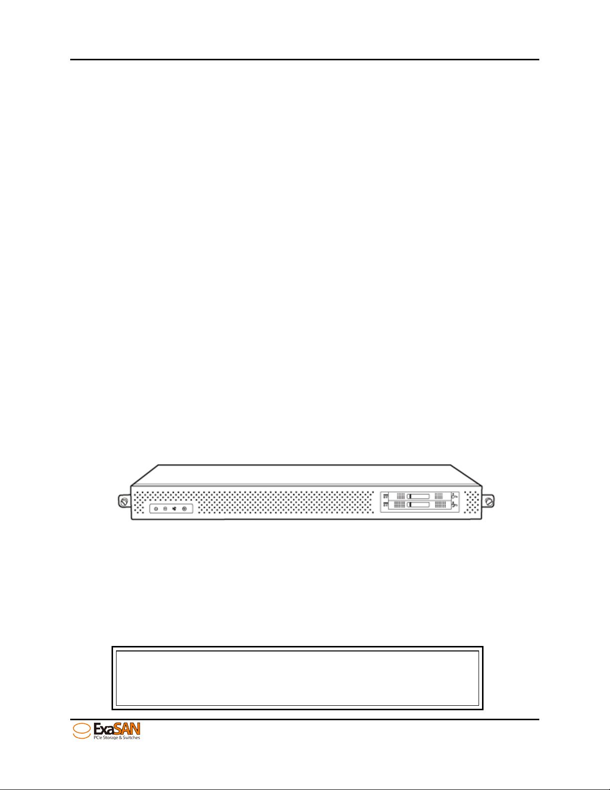
1.1.3.1 ExaSAN PCIe 2.0 SAN switch – SWF16
The SWF16 is a rack-mount PCIe 2.0 switch supporting up to 12 clients and 4 PCIe RAID
storages.
Figure 3: SWF16 Front view
The switch includes a chassis, main controller, MDC package and two 8GB SLC SSD
mirrored for Metadata.
1.1.3.2 ExaSAN PCIe 2.0 Storages
To setup an ExaSAN SAN environment, users need an ExaSAN switch, ExaSAN storages,
cables, HBAs, and SAN software
The hard drives installed in A12S2-PS or B08S2-P S sh o uld b e
User Guide Page 1-3
Page 14
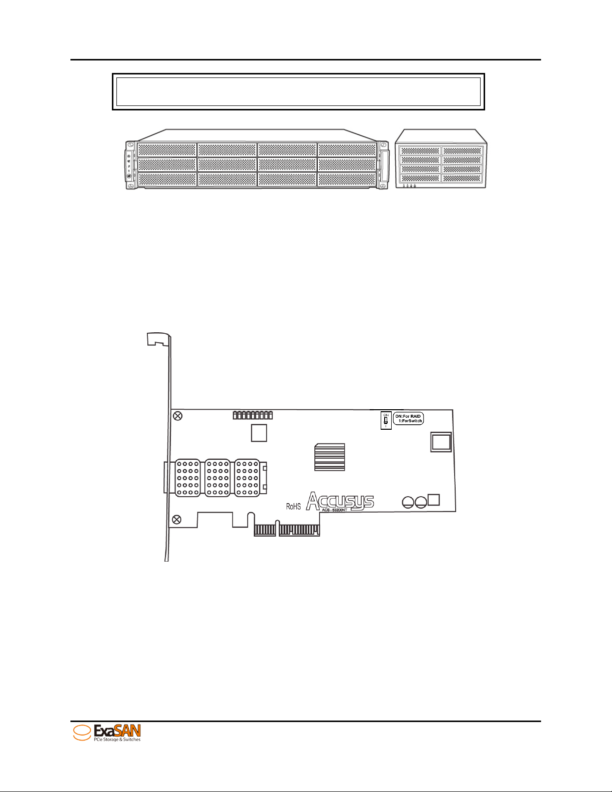
Integrator/Value Added Reseller if you need ass istance in
purchasing these components.
1. Introduction
Figure 4: ExaSAN PCIe 2.0 Storages (A12S2-PS & B08S2-PS)
1.1.3.3 ExaSAN QSFP Host Bus Adapter (ACS-63200NT)
The ExaSAN QSFP HBA (Figure 5) requires an available PCIe x4, x8, or x16 slot in your
client system. Note that the PCIe slots on some motherboards are for graphics cards
only. (Check your motherboard documentation or ver ify w ith t he motherboard vendor
for compatibility. Also note that some PCIe x4 or x8 slots only share or run at PCIe1.1
speed, so please be advised to consult your motherboard documentation to take
advantage of ExaSA N speeds
Figure 5: ACS-63200NT (Z1M) HBA card
1.1.3.4 QSFP (Quad Small Form-factor Pluggable) PCIe Copper or Optical Cables
A 2m QSFP Copper Cable is in c luded in your ExaSA N st o rage system package. You can
use it to connect it to one of the four storage ports on SWF16.
Optional QSFP cables (Figure 6) are available at varying lengths in copper or optical
1. 2m QSFP Copper Cable, (black in color)
2. 5m QSFP Copper Cable, (black in color)
User Guide Page 1-4
Page 15
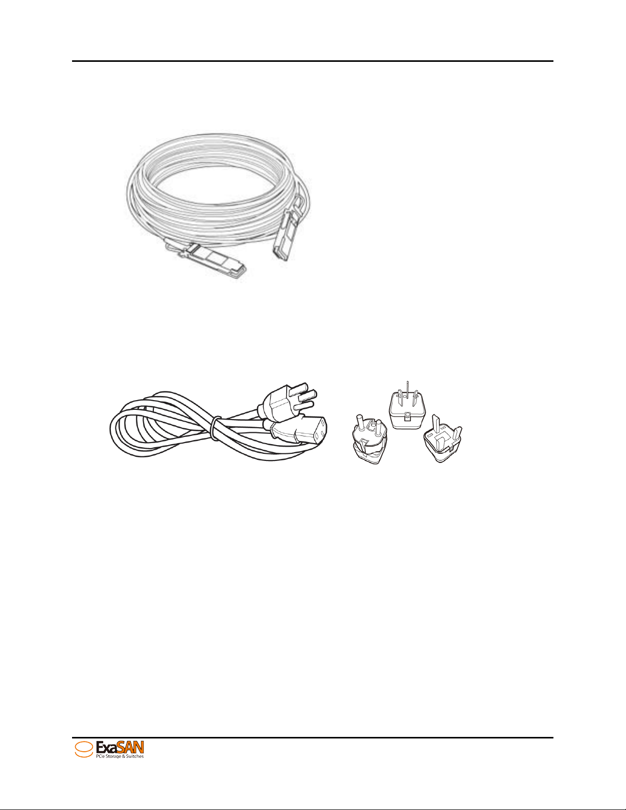
3. 10m QSFP Optical Cable, (orange in color)
4. 30m QSFP Optical Cable, (orange in color)
5. 50m QSFP Optical Cable, (orange in color)
6. 100m QSFP Optical Cable (orange in color)
1. Introduction
Figure 6: QSFP optical cable
1.1.3.5 Power Cord & Power convertors
Two AC Power Cords (Figure 7) are included in the SWF16 package. We also provide
three types of power convertors – EK, AU, EU, in addition to the US standard power cord.
Figure 7: Power cord & Power converters
1.1.4 Key Features of SWF16
1. Host Interface
• PCIe2.0 5Gb/s x4 lanes, for transfers up to 20Gb/s. 12 ports
2. Storage Interface
• PCIe2.0 5GB/s x4 lanes. 4 ports
3. Embedded MDC function
• Two 8GB SLC SSD installed and mirro red to store metadata o f t he SAN
environment
• SANit MDC software instal led.
4. Management
• Web-based GUI, cross-platform ex ecutable
• Monitor and control via Web GUI of enclosure components
User Guide Page 1-5
Page 16

1. Introduction
• LED indicators for enclosure status
• Event log download from Web GUI
• Supports both in-band and out-band managem ent
• Supports RAID managem ent by E FI and BIOS
• Supports firmware upgrade via GUI
• Supports SNMP
• Supports remote management
5. Enclosure
• FAN, Power, Temperature status LED indication in the front faceplate.
• Dimensions: 43.8mm(H) x 447mm(W) x 410mm(L)
• Weight : 6.9 Kg(15.21 lb)
6. Supported OS
• Windows XP/2003/Vista/2008 and Windows 7(32/64-bit, Miniport and Storport
driver, WHQL certified)
• Linux: Red Hat, SUSE, Fedo ra, CentOS, Debian, etc.
• MAC: OS X( 10.5, 10.6, 10.7, 10.8 and later)
7. Operating Conditions
• Humidity: 5% - 85%
• Operating Temperature: 0degC – 40degC
• Certification: RoHS, U L, CE , FCC, C-Tick, BSMI
8. QSFP HBA
• 20Gb/s PCIe2.0 x4 HBA
• Short, low profile, form factor card
• Dimension 110 x 68.9 mm
• Standard bracket (low profile available and included)
9. QSFP Cable
• Connector PCI Express 2.0 x4
• Copper cable lengths: 2M (standard; included with ExaSAN storages),
5M (optional)
• Optical cable lengths: 10M, 30M, 50M , 100M( a ll optical ca bles are opt ional)
1.2 Unpacking the System
Your ExaSAN SWF16 is shipped in special packaging (Figure 8) to provide protection
during transportation, as w el l as to facilitate simple and saf e rem oval from the carton( s).
Note that different co m po n ent s m ay be shipped in separate c artons.
User Guide Page 1-6
Page 17
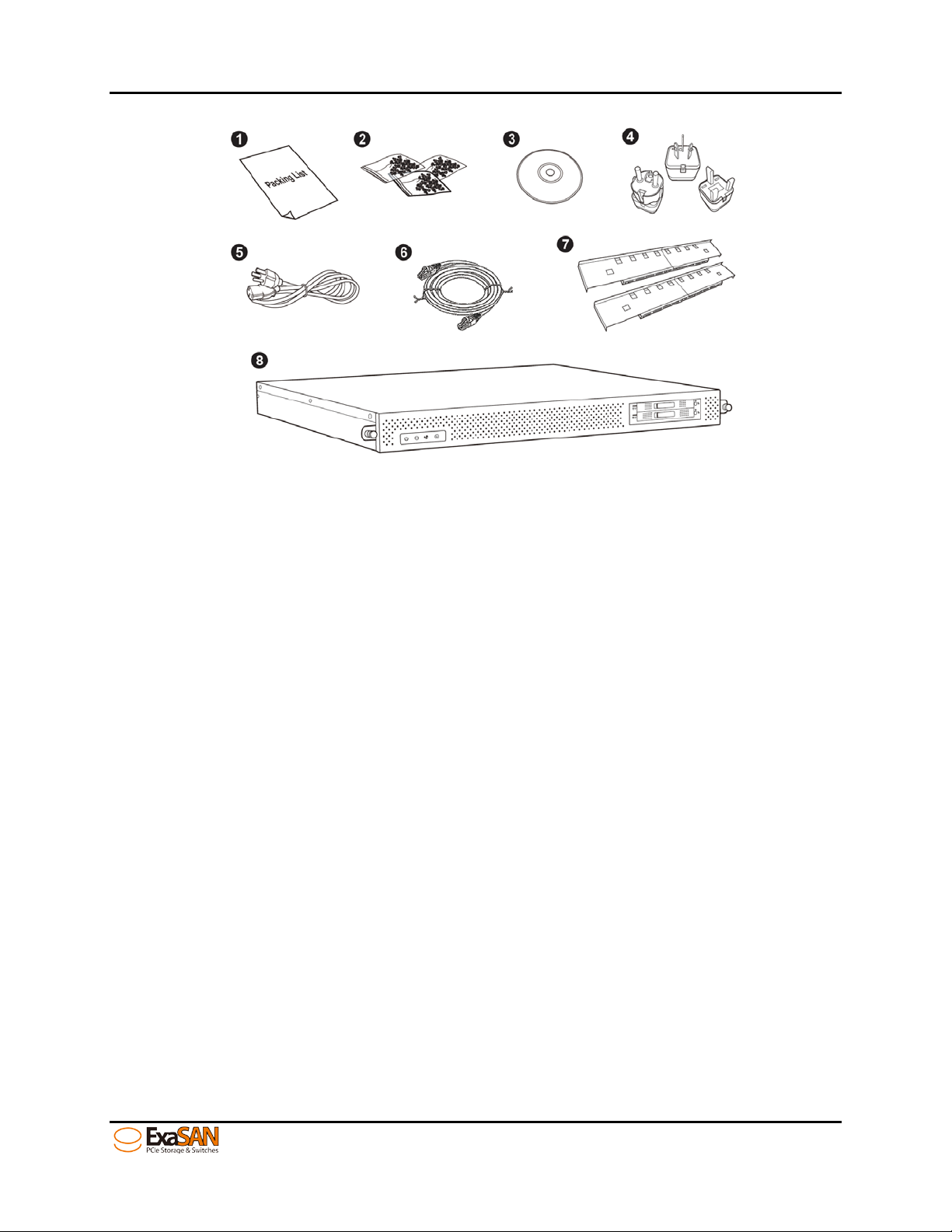
1. Introduction
Figure 8: SWF16 packing list
1.2.1 What Is In Your Order
Your ExaSAN System Int egrat or/Value Added Reseller should have helped yo u assess,
identify, and order all n ec essary system component s and accessories not inclu d ed in
the SWF16 packaging. If you order ed t h e complete SWF16 system solution, your order
includes e very t hing described in Se ction 1.3.
There are generic system co m po nen ts and accessories req u i red by the ExaSAN solution
but not included. Please refer to Section 1.5, “ What Else You Need” for addition al
information.
1.2.2 Checking the Equipment you’ll need
Section 1.1.3 has a hardware list of all the equipment you’ l l need t o set up the ExaSAN
SAN environment. Check carefully ag ainst that list; verify that yo u h ave all of the system
components and acc essories before commen c ing h ardware installat ion.
1.2.3 Unpacking
Follow the steps below to open the carton and remove the system fro m its packaging. .
1. Read Chapter 2, “Preparing to Install ExaSAN SWF16”
2. Remove any packing material on the outside o f th e carto n .
3. Cut the tape at the top of the carton. If you use a long cutting instrument, exer cise
care to avoid damaging t h e con t ent i n side.
4. Open up the top flaps of the carton to reveal the cont en t inside. Remove the
protective foam on top of the system. Carefully remove each item from inside the
carton.
User Guide Page 1-7
Page 18
1. Introduction
1.3 What’s in the Box
Carefully check your carton contents against the included packing list, or the inside
flap of the box, and your original purchase order. You should have the items as
described in the sections below.
Contact your Accusys System Integrator/Value Added Reseller or Accusys Customer
Service (see Appendix C “Customer Service and Technical Support” for more
information) to report any missing item.
1.3.1 SWF16 System
Your ExaSAN RAID disk system carton contains the following items:
1. PCIe 2.0 SAN switch system – SWF16 (x1)
2. Accessories package (x1)
3. MDC package (had been inst alled in SWF16) (x1)
1.3.2 SWF16 Accessories
The Accessories package includes the followin g item s. T h ese items can also be ordere d
and shipped separat ely from Accusys.
1. Packing list (x1)
2. Screw pack (x3)
3. ExaSAN installation DVD (x1)
4. Power converter UK, EU, AU to US (x3)
5. AC power cord (x2)
6. Ethernet cable (x2)
7. Rack mount bracket set (x1)
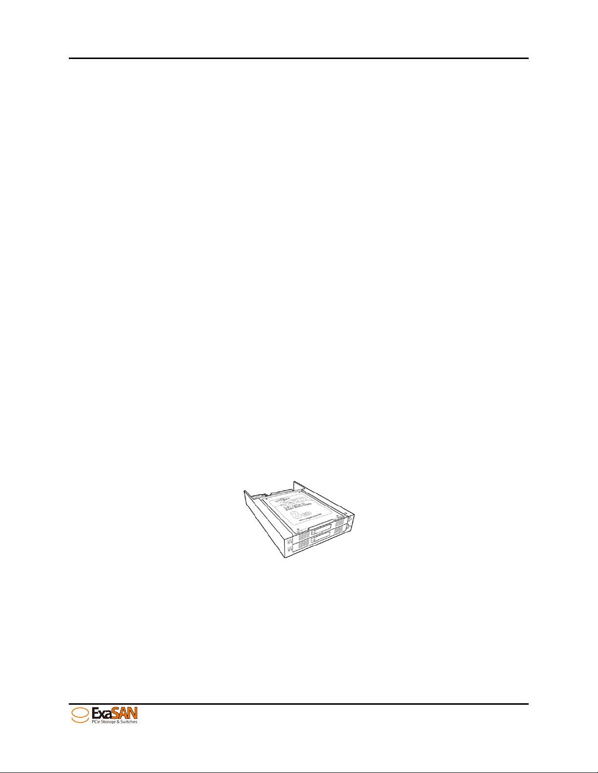
1.3.3 MDC package
The MDC package includes one mirror device, two SLC 8GB SSD and SANit MDC
software. MDC package is already installed in the SWF16. The SANit metadata would
be stored in the mirror de vic e in th e SSD s.
Figure 9: mirror device and SSD
User Guide Page 1-8
Page 19
Flashing Blue
1. Introduction
1.4 Your SWF16 at a Glance
This section helps you get familiar with the physica l ap pearance of your ExaSAN SWF16
1.4.1 ExaSAN SWF16
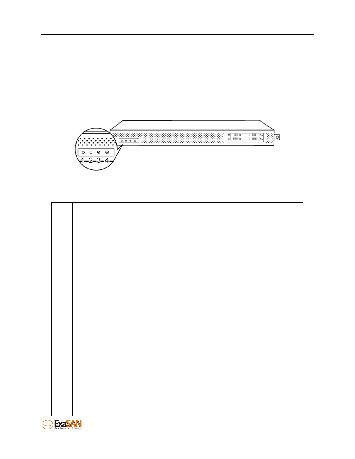
1.4.1.1 SWF16 Front Panel & LED Indicators
Figure 10: SWF16 front view
Item Name Color Description
indicates the host is booting.
Solid Blue indicates the subsystem
1 System Power Blue
power supplies are working normally.
No Light indicates the power is off
Flashing Blue indicates the host is
accessing.
2 Access Status Blue
No Light indicates standby or no
power
Solid Blue indicates the hardware
included fan, power supply are
working normally.
Hardware
3
Blue/Red
Status
Solid Red indicates some hardware
failed. Please check the switch web
GUI for more detailed information.
User Guide Page 1-9
Page 20
Controller Status
Beeper mode
Turn on the swi tc h (SW F16)
One short beep
System kernel Panic
Continuous beeping
Fan Failure
Three short beeps (Repeating)
Fan speed is under 5500RPM
Three short beeps (Repeating)
Power Failure
Three short beeps (Repeating)
Temperature Failure
Three short beeps (Repeating)
Note
switch web GUI to isolate the fault condition.
1. Introduction
No Light indicates the LED failed or
power off
Indicates the controller status
• Flashing Blue indicates the
controller is booting for link
4 Link LED Blue
• Solid Blue indicates the
controller is ready for link to a
client.
• No light indicates the controller
is inactive.
1.4.1.2 Beeper Codes
Three short beeps indicate multiple possible faults, please check the
User Guide Page 1-10
Page 21
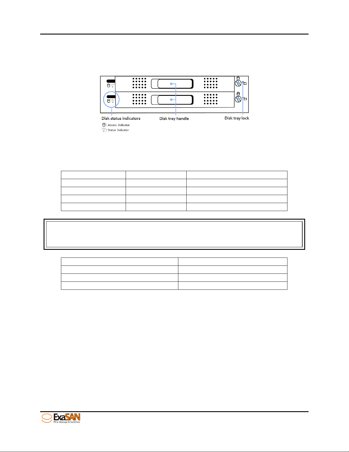
Status indicator
Access indicator
Disk status
Green
Off
Disk is properly in st alled
Green
On/flash (Yellow)
Disk is being acces sed
Red
Off
No disk installed or disk failure
Flash (Red/Green)
On/flash (Yellow)
Disk is rebuilding
Note:
fast beeping sound will indicate an error or disk failure. See below:
Sound of beeping
System Status
Bi~~
System boot up and ready
bi—bi—bi—bi…and so on
MetaData rebuilding
bi-bi-bi---bi-bi-bi… and so on
One SSD has failed
1. Introduction
1.4.1.3 Mirror device Indicators
Figure 11: front view of mirror device
Table of LED Status
A beeper will sound to indicat e status. A slow beep indicate s dat a rebuilding. A
User Guide Page 1-11
Page 22
1. Introduction
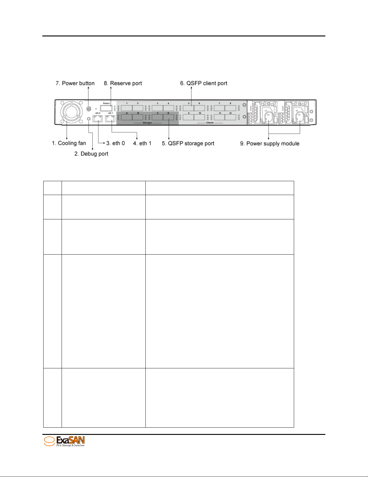
1.4.1.4 SWF16 Rear Panel
Figure 12: SWF16 back view
No. Name Description
Maintains “SWF16”, the switch away
1 Cooling fan
from overheating.
Connects to maintenance equipment.
2 Debug port
This port is only for testing or debugging
in Accusys internally.
Controls web GUI of the SWF16 through
this por t.
• The default IP is “192.168.0.25”
• The port support DNS function but
eth0 Ethernet port
3
(Management Port)
we don’t recommend using DNS
function here.
• When the network connection is
normal, the left LED would stay on
orange light and the right LED
would be flashing on green light.
Setups as a private port for MDC
eth1 Ethernet port
4
(SAN Private Port)
• The default IP is “192.168.1.25”
• The port doesn’t support DNS
function.
• When the network connection is
User Guide Page 1-12
Page 23

normal, the left LED would stay on
1. Introduction
orange light and the right LED
would be flashing on green light.
Connects the ExaSAN series PCIe 2.0
storage (A12 S2-PS or B08S2-PS).
Access LED (top):
• Flashing Blue indicates storage
accessing is in progress.
• No light indicates no storage
accessing.
Link LED (middle):
• Solid Green indicates the
controller is connected normally.
5 QSFP storage port
6 QSFP client port
• Flashing Green indicates the
controlle r downgrade to less
lanes of PCIe
• No light indicates “no power” or
“no connection” to the ExaSAN
storage.
Fail LED (b ottom) :
• Solid Red indicates the port is
connected to a client (wro ng
connection type).
• No light indicates “no power” or
“no error”.
Access LED (top):
• Flashing Blue indicates storage
accessing is in progress.
• No light indicates no storage
accessing.
User Guide Page 1-13
Link LED (middle):
• Solid Green indicates the
controller is connected normally.
Page 24
Flashing Green indicates the
1. Introduction
•
controlle r downgrade to l e ss
lanes of PCIe
• No light indicates “no power” or
“no connection” to the ExaSAN
storage.
Fail LED (b ottom) :
• Solid Red indicates the port is
connected to a client (wro ng
connection type).
No light indicates “no power” or “no
error”.
Control the power of SWF16
• Push the button to turn on the
7 Power button
8 Reset hole
power of SWF16.
• Push the button to turn off the
power of SWF16 and it would be
shut down automatically.
• Push the button for 5 seconds to
shut down the power of SWF16
Immediately.
If you want to reset the all setting of the
SWF16, you could use a needle or pin to
push into the hold for 13 seconds . Then
you’ll hear two short beeping “bi-bi”
and wait for the SWF16 restarting. The
whole setting would go back to default.
Caution:
If you push reset hole but are still
connected to the clients, you might
damage important data in the SAN.
User Guide Page 1-14
Page 25
9 Reserve port This QSFP port is reserved.
Connects to power sources with two
1. Introduction
10 Power supply module
power cord to the redundant modules.
If one power failed, the SWF16 can still
work normally.
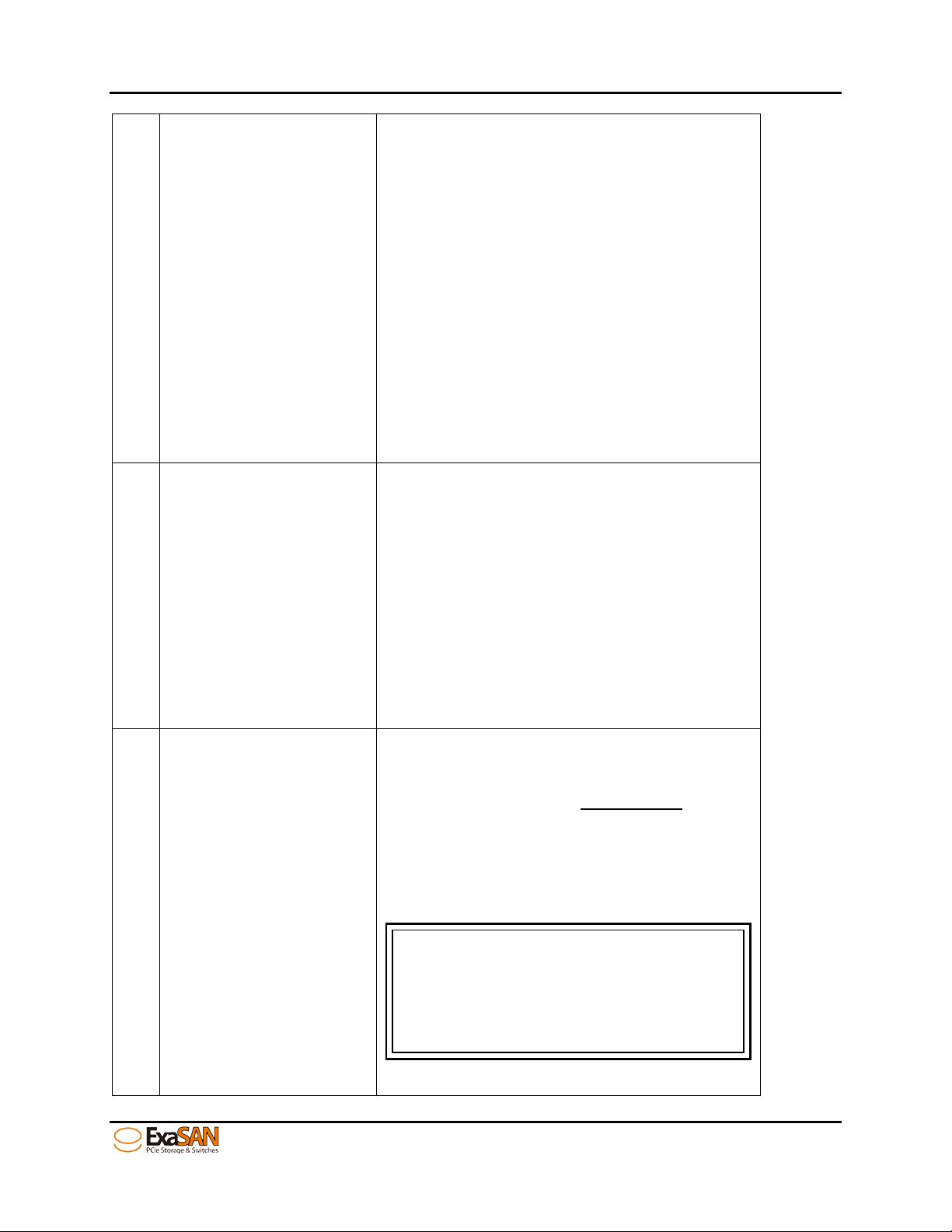
1.4.2 ExaSAN QSFP Host Bus Adapter (HBA) and LED Indicators
Figure 13: HBA LED indicators
No. Name Description
For connection with one of the Host
1 QSFP Connector Port
Module Ports on the switch rear panel or
B08S2-PS directly.
Jumper Switch LED
2
Indicator
• Off (no light at all) indicates the
jumper pin in question is set to “On”
position. In this state, the card is
ready for DAS direct connection
with ExaSAN storages, “A12S2-PS or
B08S2-PS”.
• Solid amber indicates the jumper pin
in question is set to “1” position. In
this state, the HBA card is ready for a
SAN connection. See Section 3.1.2,
“Installing the HBA Card,” for
additional information.
User Guide Page 1-15
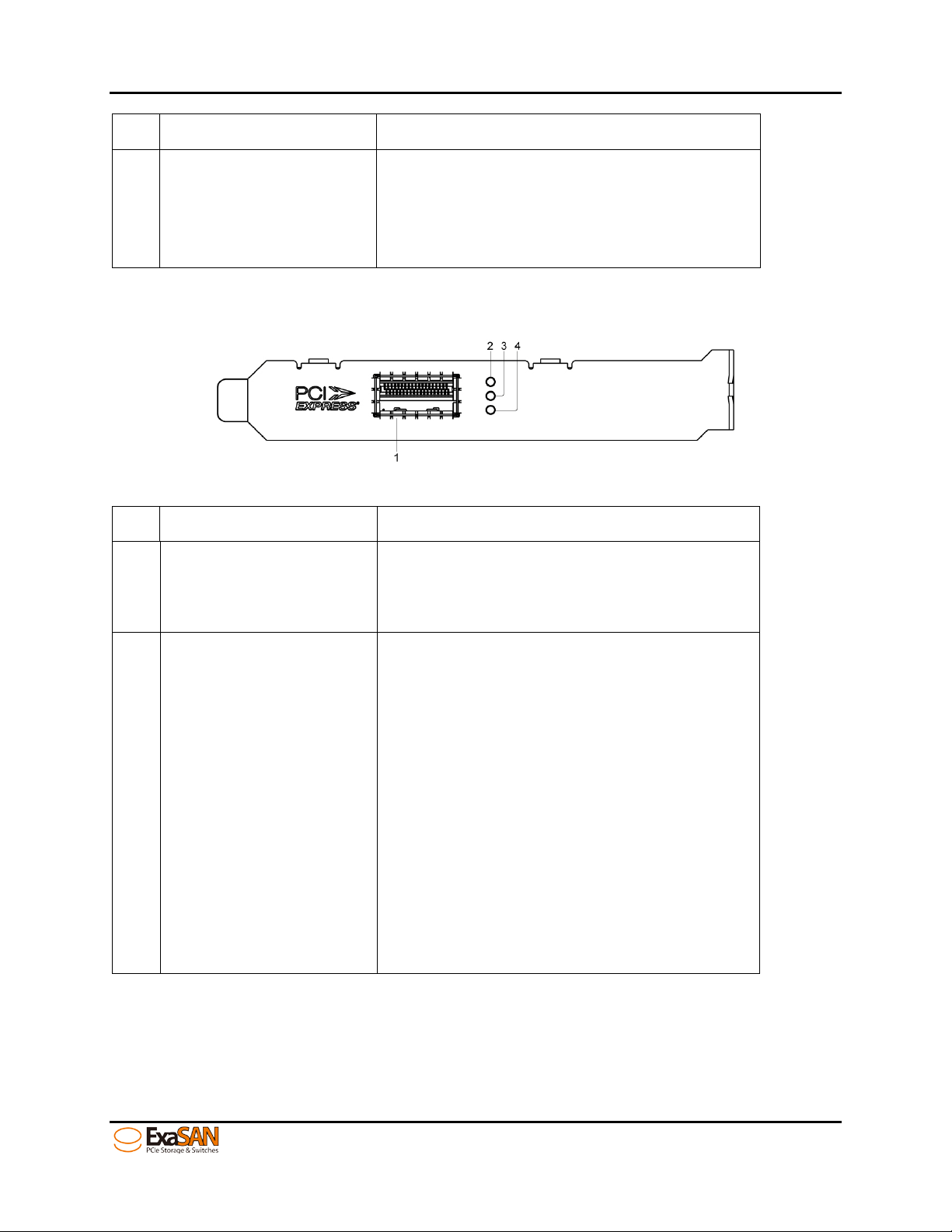
Page 26
Note
(The LED
If you have properly
RAID controller, one set of 4
LEDs will be constantly lit. The second set of 4
a PCIe Gen2 connection.
1. Introduction
• Solid green indicates connected
PCIe 2.0 link;
3 Link LED Indicator
4 Access LED Indicator
The eight LED indicate the connection status of the HBA
closest to the bracket does not light up.)
connected the HBA to the B08S2-PS
consecutive
consecutive LEDs indicates the type of PCIe connection - flashing
LEDs indicate a PCIe Gen1 connection, while steady LEDs indic ate
• Flashing green indicates connected
PCIe 1.0 link or downgraded speed.
• Off (no light) when there is no link or
indicates a link with trouble.
Flashing blue while there are data
access activities with the connected
device.
No light indicates the host is not
accessing
User Guide Page 1-16
Page 27

Note
unsuitable use of ExaSAN items.
1. Introduction
1.5 What Else You Need
ExaSAN software requires suitable hardware and accessories to fully t ake advantage of
this software. The following section covers all of the software and hard w are which you
may need to purchase sepa rat ely. Please inquire with your ExaSAN reseller f or more
details.
Accusys shall not be liable for products mistakenly purchased and/or
SAN environment
The key purpose of a SAN (Storage-Area-Network) environment is to allow sharing of
storage connected to the switch among the various clients connected to the switch to
take advantage of collaborative workflows and achieve storage purchase efficiencies
To set up and manage read/write access to the shared storage volume and keep track
of metadata of what files were written wh ere, when, how much was wri tten, by who,
etc, ExaSAN’s SANit SAN management software along with MDC is required to keep
order.
Please kindly see the below d i agram for more detail.
User Guide Page 1-17
Page 28

WARNING:
storage will be lost.
1. Introduction
Figure 14: ExaSAN SAN environment
Hardware
Accusys recommends getting the advice from your reseller o f d istributor regarding
setting up the SAN to achieve the objectives you are looking for
1. System computer for clients, running the editing, finishing, etc., applications you will
use. We recommend HP Z series, Dell workst ations or Apple Ma cPro workstations.
The MDC is very important in a SAN configuration. If the Metadata
stored in the MDC is lost o r dam aged , access to data stored in SAN
2. Storage for ExaSAN. We recommend A12S2-PS for speed, capacity, scalability, and
rackmount applicat ions. We recommend B08S2-PS for speed, small footprint, or
transportable consi derations.
3. Ethernet switch and cables: An Ethernet switch is required to provide a private
network for SAN man agem en t sof tware managing the SAN configuration. It does
not need to be connected to an external network. If your workstation needs the
Ethernet connection to an external network for web or email access, we suggest
using a separate network. Please choose good quality products, protected by
manufacturers’ warr anty to assure the safety an d st ability of the SAN network .
User Guide Page 1-18
Page 29

2. Preparation
2. Preparing to Install ExaSAN SWF16
User Guide
Page 30

2. Preparation
2. Preparing to Install ExaSAN SWF16
To ensure safe and smoo t h operation of your ExaSAN SWF16, it is essential that you
choose an appropriate location for the system , an d provide an appropriate operating
environment and adequate power for all components of the system. As you plan for
installation, follow the guide lines below to ensure that the system an d its environment
are safely and approp riately positioned for effi ci en t o peration and service.
2.1 Precaution for Handling the System
Take the following precautions to avoid damage to the system or potential injury to
you.
1. Prepare a flat, sturdy surface before removing the system from its packaging. The
table or cart that will hold the system should be as close as possible to the system’s
carton.
2. Ensure that all power switches have been turned off and all power cords
disconnected to prevent personal injury and damage t o t he h ardware.
3. Static electricity can damage electronic components of your system. Follow the
guideline s below to a v oid such damage:
a. Work in a static-free environment
b. Wear a grounded anti-static wrist strap
c. Store uninstalled components in anti-static bags
d.
Handle circuit boards by their edges and avoid touching chips and
connectors
2.2 Choosing the Location for the System
The ExaSAN SWF16 is designed as a rack-mount solution. Depending on where your rack
is located, you should keep the following points in mind when determining where to
place your system.
1. Measure the amount of available space in the ra ck. The amount of space required
for the SWF16 is 1U rack space. (dimensions are L410mm x W447/480.2mm x
H43.8mm)
2. Measure the distance between any two components that need to be connected
via cable(s). This measurement will help you determine the length of the required
cable(s). Or if you’ve already purchased the cables, determine the proximity of the
components in questio n.
3. Leave sufficient room, at least two inch es, around the unit to allow air ventilation.
4. Do not b lock or cover any of the ventilation holes in the front and back panels of
the unit. Consistent airflow is essential to keeping the system operating efficiently.
5. Allow additional room at the front and back of the unit for service.
6. The ExaSAN SWF16 uses several cables and cords. It’s a good idea to determine
how they will be arranged at the rear of the system, and where the cables will be
routed to connect to the host systems and RAID disk systems.
2.3 Electrical Power
At your chosen location for the ExaSAN SWF16, make sure that the electrical circuitry
and power outlets are sufficient for the combined power needs of all hardware
User Guide Page 2-1
Page 31

2. Preparation
components. To plan for safe and adequate power to the system, follow these
guidelines:
1. Check the documentation for all hardware components at the chosen location to
determine their power requirements. Then make sure that the available power
supply for that location is sufficient for the planned components.
2. If you need assistance determining the power needs of the components at the
chosen lo ca tion, consult an elect rical expe r t who is familiar with your facilit y.
3. When possible use surge protectors or power conditioners as part of the installation.
4. When planning for electrical power, make sure you have more power than the total
power requirements specified for all components. Also make certain that the power
load is distributed evenly among circuits to that location. Consult an electrician or
other expert if you need assistance with planning for the power needs of your
components.
5. When possible, plug the redundant power supplies onto d ifferent circuits.
6. Make sure that the power outlets for all hardware components are grounded
according to local and national standards. Consult an electrician if you need
assistance with grounding.
2.4 Operating Environment
The operating environment for the ExaSAN SWF16 must meet certain requirements:
1. Verify that the temperature range of the chosen location is within the limits
established for the system and all other compon ent s.
2. Make certain that the chosen location has adequate ventilation to maintain the
necessary temperature range.
3. If there are multiple hardware components installed at the chosen location,
consider ad ditional co o lin g m easures to assure efficient oper at ion o f the system and
other components.
4. Environment parameters:
a. Operating temperature: 0°C to 40°C (32°F to 104°F)
b. Non-operating temperature: -4 0°C to 70°C (-40°F to 158°F)
c. Operating humidity: 5-85%, non-condensing
d. Storage humidity: 0-95%, non-condensing
2.5 Security
To ensure the security o f t he E x aSAN SWF16, make certain that the chosen location
meets your security re qui rements.
User Guide Page 2-2
Page 32

3. Installation
3. Installing the ExaSAN SWF16
User Guide
Page 33

Caution
Check with the motherboard vendor for compatibility.
3. Installation
3. Installing the ExaSAN SWF16
Follow the steps in this chapter to prepare your Ex aSAN SWF16 for installation.
Below is an outline of the installation steps for you to follow.
Step 1 Unpacking the switch, inspecting the packing list
Step 2 Installing disk dri v es, pl ease refer to the A12S2-PS or B08S2-PS User Manual for
instructions
Step 3 Installing HBA (refer to the section 3.1.1)
Step 4 Connecting SWF16 to the ExaSAN storages (refer to the section 3.1.2)
Step 5 Connecting SWF16 to the Host Systems (refer to the section 3.1.3)
Step 6 Connecting the Switch LAN (refer to the section 3.1.4)
Step 7 Power-on sequences (refer to the section 3.2.1)
Step 8 Create Array for SAN Configuration through switch web GUI.
Step 10 SAN Configuration through SANit GUI menu.
3.1 Hardware installation
Follow the instructions i n this section to hook up all your hardware components of th e
ExaSAN SWF16 Do not turn the power of any individual component on until instructed.
When all components are properly connected, follow the instructions in section 3.3.1
“Powering On” to turn the components on in the prescribed order.
3.1.1 Installing the HBA Card
Before the ExaSAN SWF16 is ready to be connected and powered on, you must install
the HBA card in the workgroup client system. The HBA card is compatible with PCIe x4,
x8, and x16 slots. If a choice is given, use the fast est PCIe slot available. Although the
HBA card is compatible with both PCIe 1.1 and 2.0 st and ards, the latter is required to
achieve 20Gb/s speed s…
PCIe slots on some mot h erboards are for graphics cards only.
Follow these steps to in st al l th e c ard in each host system:
1. Make sure that the client system is turned off.
2. Open the client system’s outer casing cover, check with your vendor
documentation for instructions if nece ssary.
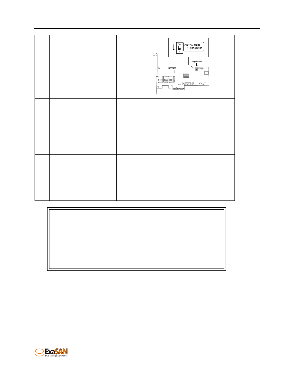
3. Re-position the HBA card so that you are facing jumper switch as shown below. You
can use the jumper switch t o con fi g ure the HBA for DAS or SAN usage. Set the
jumper switch before installing into the host
• DAS mode: When the switch is in t he "On” position, the HBA card is enabled for
RAID (Direct-Attached Storage B08S2-PS) mode.
• SAN mode: In the “1” pos ition, the HBA is enabled for switch (SAN) mode.
User Guide Page 3-1
Page 34

3. Installation
Figure 15: HBA card’s jumper switch
4. Locate the available PCIe slot; remove the blan k pl ate if o ne is present, save the
screw for later use.
Figure 16: Install HBA card
5. Position the connector of the card over the slot, insert the connector into the slot,
press gently but firmly until it is s ecurely sea t ed.
User Guide Page 3-2
Page 35

3. Installation
Figure 17: Install HBA card on a PCIe slot
6. Use the screw that you saved in step 2 to secure the metal bracket of the card t o
the system case. David, the ima ge lo o ks like a PCIe x16 card
7. Replace the outer casing cover.
3.1.2 Connecting SWF16 to the ExaSAN storages
1. Connect to the ExaSAN storage (B08S2-PS or A12S2-PS) with a QSFP PCIe cab le.
Insert one end of the QSFP cable into the host port on the rear panel of the ExaSAN
storage. Your cable connector is securely plugged when you hear a “click” If you
do not hear or sense a click, p lease re-insert the QSFP connector. If you need to
unplug the cable, pull the ring on the connector firmly until it is detached from the
port. Note that the QSFP used in the photo illustration below is a QSFP optical cable.
If the distance betwee n th e sw itch and the host system is less than 2 meters in your
case, the included QSFP copper cable will suffice.
Figure 18: Connecting PCIe cable to B08S2-PS or A12S2-PS
2. Insert the other end of the QSFP cable into the storage port on the ExaSAN SWF16.
The cable connector is secu rely plugged when you h ear a c li ck.
User Guide Page 3-3
Page 36

Caution
remove the QSFP PCIe cable when in
use to avoid data loss and corruption.
3. Installation
Figure 19: Connecting the PCIe QSFP cable to the storage port (black color)
3. Plug a power cord into the AC power-in port in the storage system;
power on yet.
Figure 20: Connecting the power cord to the storage (B08S2-PS or A12S2-PS)
Once powered on, Do NOT
do not turn
3.1.3 Connecting SWF16 to the Host systems
1. Insert the end of the QSFP cable into the PCIe port on th e HBA card, which you
installed on the host system earlier in Section 3.1.1. The cable conne ct or is securely
plugged when you hear a click.
Figure 21: Connecting the QSFP cable to a host system
2. Insert the other end of the cable into the client port (orange color) on the SWF16.
User Guide Page 3-4
Page 37

Note
3. Installation
Figure 22: Connecting the PCIe QSFP cable to the client port
3.1.4 Connecting the switch LAN and power cord
1. Insert the Ethernet ca ble into eth0 (managem en t port ) and eth1 (private port for
MDC) on the SWF16. The default IP addresses are 192.168.0.25 and 192.168.1.25.,
respectively.
Figure 23: Connecting the Ethernet cable to eth0 and eth1
2. After connecting th e E t h ernet cables, please connect the power cords to the both
power supply modules.
Figure 24: Connecting the power cords to the power supply module
User Guide Page 3-5
Page 38

SWF16 will beep unless both power cord s are plugged in.
Caution
n sequence. Failure
to do so may result in some features not functioning properly.
3. Installation
3.2 Powering the System On and Off
3.2.1 Powering On
Before powering on, make sure that all cables and cords are properly installed and
connected.
1. Press the power button on the rear panel of storag e fir st . Wait until all the LEDs on the
left handle turn blue, then,
Turn power on for the ExaSAN SWF16 by switching on the Power button. Wait for the
“Link LED indicator” (refer to Section 1.4.1.1, “SWF16 Front Panel”) to turn into a solid
blue state. Soon thereafter, you will hear 3 beep s si gn i fy ing that the clients can now
be powered on. You might hear other beeps, but the 3 beeps are significant,
indicatin g that it has fu lly booted up.
3. Turn on clients, MDC first (for non-SWF16 ExaSAN switches), t hen t he rem aining client
workstations.
Figure 25: power on sequence
It is important to follow the correct Power O
User Guide Page 3-6
Page 39

3. Installation
3.2.2 Powering Off
If you need to power off the entire system, such as when switch or R AID system requires
firmware updates, adding a RAID system or client computer, power off in the reverse
order of Powering On. Before turning off SWF16, turn off the all the client computers first.
Wait for complete client computers to shut down and then the SWF16, then the ExaSAN
storage systems.
During RAID initiation or disk drive rebuilding, you can turn off the client computers only
and leave the SWF16 and storages powered on.
Figure 26: power off sequence
3.3 Installing the Installer Package
3.3.1 Before You Start
Before the installer pac k age can be installed on Windows, Mac, and Linux platforms,
makes sure you have com pl et ed the following:
• Setup your ExaSAN storage completely. Please refer to t he E x aSAN storages’ user
manual.
• Install the HBA card to your host server. Please refer to Section
Card”.
• Connect the QSFP cable between ExaSAN storages and SWF16. Please refer to
Section
3.1.2, “Connecting SWF16 to the Ex aSAN storages”.
• Connect the QSFP cable between SWF16 and the host server. P lease refer to
Section
3.1.3, “Connecting SWF16 to the Host systems”.
• Connect the switch LAN cable and power cord. Please refer to Section
“Connecting the switch LAN and power cord”.
• Power on the ExaSAN storages, SWF16 and t h e ho st server in the correct seq uence.
Please refer to Section
3.2.1, “Powering On”.
, “Installing HBA
3.1.1
3.1.4,
User Guide Page 3-7
Page 40

Note
etc…) user’s manual.
3. Installation
3.3.2 Installing the installer package
The installer package can be downloaded from t he Accusys website. Go t o t h e
Accusys support p a ge (http://www.accusys.com.tw/support/download.html) for
available downloads. Or you can fin d it from the ExaSAN ins t a llation DV D. If you need
more info or tech support, please contact your system integrator of ExaSAN product or
Accusys FAE Dept. (see Appendix C “Customer Se rvice and Technical Sup po rt” for
more information)
3.3.2.1 Installing on MAC and Windows
1. Insert the installatio n DVD into the DVD drive of the MAC or PC.
2. For Macs, unzip and execute “DVD-ROM/ExaSAN/For SAN/SWF16/Installer
package/Mac Installer/Accusys_IP_Mac_NT_x.x.x.zip ".
For PCs, unzip and execute “DVD-ROM/ExaSAN/For SAN/SWF16/Installer
package/Windows Installer/Accusys_IP_Mac_NT_x.x.x.zip”.
Figure 27: Windows installer Package
After you install the ins taller package completely, you’ll see
“RAIDGuard X” icon in the host. “RAIDGuard X” is a powerful tool
which supports remote monitoring of multiple controllers that are
connected to the same network. If you want to configure your
storages in advance, you can use RAIDGuard X to do so. If you just
need the basic functio n t o setup y o ur st o rages, you can use
ExaSAN switch web GUI to do so. Please refer to the section “4.
Using ExaSAN switch web GUI”. The detailed using information of
RAIDGuard X, please refer to yo ur st orage’s (A12S2-PS, B08S2-PS,
3. Follow the onscreen instructions. Sampl e screens shown below are from a Windows
installation.
User Guide Page 3-8
Page 41

3. Installation
Figure 28: GUI welcome page
4. Agree the License Agreement and click NEXT.
Figure 29: GUI license page
5. Select the path to install ExaSAN instal ler package and then click NEXT.
User Guide Page 3-9
Page 42

3. Installation
Figure 30: GUI destination select page
6. Click NEXT to continue with the Standard installation, which will automatically install
the Driver and the RAIDGuard X Client.
Figure 31: GUI installation type page
7. Click “Finish” to complete the installation.
User Guide Page 3-10
Page 43

Note
Storport and miniport are new storage drivers created by
Microsoft for Windows Server 2003 and future Windows operating
systems.
3. Installation
Figure 32: GUI installation successful page
3.3.2.2 Installing on Linux
Driver Installatio n
1. Copy the ExaSAN driver files onto your GUI desktop. Open a terminal w indow.
2. Type the following commands:
# cd 'root/Desktop/Accusys_LinuxRaid’
# make
Example:
User Guide Page 3-11
Page 44

3. Installation
The Linux compiler should now begin compiling the driver.
# ls
Example:
Verify that acs_nt.ko has been compiled. If so, plea se t y pe th e following command
# insmod acs_nt.ko
# lsmod
Example:
The driver should be now loaded in Linux.
User Guide Page 3-12
Page 45

3. Installation
3.3.3 Confirm the ExaSAN RAID system driver on OS
3.3.3.1 Confirming the ExaSAN RAID system driver on Mac
After installing the ExaSAN RAID system HBA driver on the Mac host server, confirm the
driver has been pro perly installed with the following steps.
1. Click on About This Mac.
Figure 33: to click about This MAC
2. Click on the More Info… button.
Figure 34: About This MAC
3. Click on the System Report… button.
User Guide Page 3-13
Page 46

3. Installation
Figure 35: more info About this MAC
Under the Hardware category, click on PCI Cards to bring up information on PCI cards
that are installed in the sy st em . If the driver has been correctly installed, the HBA is listed
with the Accusysntdevice.kext identifier (actual name may vary) as a RAID Controller. If
you do not see the HBA listed here, power off the host ser ver, reseat the card, and
reinstall the driver. Refer to Appendix A FAQ Q7if the problem persists.
Figure 36: MAC Pro info
User Guide Page 3-14
Page 47

Caution
If you see the HBA listed as an unknown device under Windows,
follow the driver installation steps to reinstall the driver. If you do
Device Manager, Windows does not
detect the card. Power o ff th e h o st server to reseat the HBA.
3. Installation
3.3.3.2 Confirming the ExaSAN RAID system driver in Windows
After installing the ExaSAN RAID system HBA driver on a Window s based host server,
confirm the driver has been properly installed.
Go to Control Panel -> System Properties -> Hardware -> Device Manager (depending
on the version of Windows, the path may vary). If the dri ver h as been correctly insta lled ,
the HBA is listed with the ACS-6xxxx identifier (actual name may vary) as Storage
Controllers.
Figure 37: device manager in Windows platform
not see the HBA under
User Guide Page 3-15
Page 48

Note
the storage’s user manual.
3. Installation
3.3.4 Confirm LEDs on HBA
Verify the Jumper Switch LED, Link LED, and Access LED on the backplane of t h e HBA
are appropriately lit according to your inst allation (Refer to Section 1.5.2 ExaSAN QSFP
Host Bus Adapter). If the LEDs are not on, please refer t o t he Appendix A FAQ Q3.
For more detailed usin g info about RAIDGuard X, plea se refer to
User Guide Page 3-16
Page 49

4. How to Use
4. Using ExaSAN switch web GUI
User Guide
Page 50

Note
The default IP of eth0 is 192.168.0.25 and eth1 is 192.168.1.25.
2
SANit FS Web GUI
To Configure SANit in the SWF16
4. How to Use
4. Using Switch Web GUI & SANit
After you have connected all your ExaSAN components, powered the system on, and
used a web browser in a com put er, which is in the same netwo rk , we will first need to
perform some basic configuration and setup before the ExaSAN SAN environment is
fully opera tional.
Please type the default IP in your browser and then yo u’ ll s ee th e screen as following
Figure 38: Web GUI “Main screen”
Function Description
1 Switch Web GUI To configure SWF16
4.1 ExaSAN switch web GUI
4.1.1 Entering ExaSAN switch web GUI
Please move the cons o le ar ro w o n “ E xaSAN Switch Configuration” and then click it.
User Guide Page 4-1
Page 51

Note
4. How to Use
Figure 39: Click switch web GUI
After you click “ExaSAN Switch Configuration” icon, you’ll enter the m ain page of the
web GUI as following screen sho t . If you want to go back “main screen” of web GUI,
please type the previo u s IP to go back the main screen.
Figure 40: Main page of web GUI
4.1.2 User name and Password
The default user name and password is “admin” and “00000000” (8 zeros). Please type
the user name and passwo rd t o ent er the configuration menu of th e w eb GUI as the
following figure.
User Guide Page 4-2
Page 52

User cannot change the d efault user name but password. If you forget
damage your importan t dat a in th e SAN environment.
4. How to Use
your changed password, you could push the reset button in back of
the SWF16 for 13 seconds to go back the default setting. Please refer to
the section 1.4.1.4 for more detailed info.
Caution:
If you push reset hold but not disconnected the all clients, you might
Figure 41: Enter user name and password
4.1.3 Configuration menu - Overview
The following Figure is shown the three main functions,
• Quick Setup
• Event Management
• System management
User Guide Page 4-3
Page 53

Note
but not JBOD systems.
4. How to Use
Figure 42: Overview menu of ExaSAN switch web GUI
4.2 Creating arrays by SWF16 – “Quick Setup”
If you haven’t created arrays in your ExaSAN storages that have been connect ed with
SWF16, you could crea t e arrays in the ExaSAN storages by “Quick Setup” function as
following screen.
The “Quick Setup” fun ction j u st creates arrays for ExaSAN RAID systems
The concept of cre ating arrays by “Quick Setup” function is
Figure 43: Quick setup menu of ExaSAN switch web GUI
User Guide Page 4-4
Page 54

Step 1: Choosing RAID level. You can choose R5 or R6 in the m enu.
4. How to Use
Figure 44: Choosing RAID Level – R5
Step 2: Choosing SAN Softw are. This option means what SAN software you want t o use.
Currently, SWF16 only supports “SANit” so you needn’t click the option.
Figure 45: Choosing SAN software – SANit
Step 3: Click “Next” button in the bottom right to process. Then you might see the two
kinds of screens as following. The “figure 45” indicates SWF16 had been
connected 4 pieces of E x aSAN storages “A12S2-PS”. The “figure 46” means the
SWF16 doesn’t detect an y con n ected ExaSAN storage.
User Guide Page 4-5
Page 55

4. How to Use
Figure 46: RAIDSet (find ExaSAN storages)
Figure 47: RAIDSet (find ExaSAN storages)
Step4: If the table conten t abo ut th e “ St o rage Information” is correct , please click
“Apply” button to start arrays creating. Then y o u’ ll see t h e screen as following,
User Guide Page 4-6
Page 56

Note
them, the “Apply” button would NOT been shown on the bottom right.
Note
volume because of th e performance issue.
4. How to Use
Figure 48: Arrays creating
If you connected the ExaSAN storages, w hic h had been created arr ay s in
We strongly recommend you creating 2, 4 or 8 arrays to build up your SAN
4.3 Log download – “Event Management”
Log is the very importa nt clu e t o analy ze root caused when us er m eet some problem
around the SAN environment. SWF16 web GUI provides the function to download the
log of the SWF16.
Step 1: To click “Event Management”, then you’ll find “Download” button in the middle
of the GUI.
User Guide Page 4-7
Page 57

4. How to Use
Figure 49: To find “Download” button
Step 2: Clicking “D o wnload” button to process, then you ’ ll se e a processing bar as
following figure
Figure 50: processing bar
Step 3: After the processi n g finished, you can see the log hy per-link in the middle as the
following figure.
User Guide Page 4-8
Page 58

4. How to Use
Step 4: Clicking “
Chrome web browser. The default file name of t h e log is “ diag.bin”.
Figure 51: the LOG hyper-link
LOG” to download log file in your computer. For example: Google
Figure 52: download log file “diag.bin” in Google Chrome
4.4 System Management
There are several functions in “System Management”. It includes
• Network
• Time
• Security Control
• Firmware Update
• Restart/Halt
User Guide Page 4-9
Page 59

4. How to Use
4.4.1 Configuring the network – “Network”
Users can use “NIC” option to choose “eth0” or “eth1” and then setup th e parameters.
We strongly recommend using eth0 as public network for communicating with other
computer, which is not in the ExaSAN SAN environment and eth1 as private network for
ExaSAN SAN environment.
4.4.1.1 eth0 – SAN management port (RJ45)
Users can find the follow ing info o r setup the parameters in th e page
• Disable “eth1”: Checking the box in front of “Disable eth1” to disable eth1 port.
• MAC address: User ca n find t he MAC address of eth0 in the page
• Assignment method: To setup or change the IP of eth0. The default IP address is
“192.168.0.25”.
IP address
Network Mask
Gateway
DNS server
Figure 53: “eth0” setting
4.4.1.2 eth1 – SAN private port (RJ45)
Users can find the follow ing info o r setup the parameters in th e page
• Disable “eth1”: Checking the box in front of “Disable eth1” to disable eth1 port.
• MAC address: User ca n find t he MAC address of eth1 in the page
• Assignment method: To setup or change the IP of eth0. The default IP address is
“192.168.1.25”.
IP address
Network Mask
User Guide Page 4-10
Page 60

4. How to Use
Figure 54: “eth1” setting
4.4.2 Changing SWF16 time – “Time”
ExaSAN switch web GUI support 2 types of time setting.
• Static
• NTP
Time setting would affect the time that record in event log of the SWF16.
4.4.2.1 Static
Selecting the correct t i m e an d d ate. Then click “Apply”
Figure 55: “Time” - Static
User Guide Page 4-11
Page 61

4. How to Use
4.4.2.2 NTP
When you select NTP, you need to setup a NTP server for the function. If the NTP server
that you type in doesn’t ex ist or n o t been detected, SWF16 w o u ld us e st at i c time
setting.
Figure 56: “Time” - NTP
You can enter any intranet or internet NTP server. And then click “Apply” to process.
For example: NTP server – clock.stdtime.gov.tw
Figure 57: “Time” – setup NTP server
User Guide Page 4-12
Page 62

4. How to Use
Figure 58: “Time” – processing the configuration of NTP
4.4.3 Change Password – “Security Control”
The only function in “Security Control” is to change login password for entering SWF16
web GUI. When you click “Security Control”, you’ll find the following figure
Figure 59: “Security Control”
Four steps to change the passwo rd
• Enter old password
• Enter new password
• Re-enter new password
• Click “Apply”
If users enter wrong old password, they’ll see
User Guide Page 4-13
Page 63

Note
the clients or host that connected to the SWF16.
4. How to Use
Figure 60: old password not match
If users enter different n ew password, they’ll see
Figure 61: new password not the same
Press “OK” and go over step1 to step4 to change password.
4.4.4 Firmware Update
For some reason, users might need to update the firmware of their SWF16. “ Firmw are
Update” is the function t o reach th e purpose.
Before you start to update t h e fi rm w are of SWF16, please pow er of all of
There are four steps to update the firmware of SW F16. They are,
i. To click “Choose File”
Figure 62: Firmware Update
ii. Selecting firmware file. The firmware file is a “gz” file, not txt or others.
User Guide Page 4-14
Page 64

4. How to Use
Figure 63: Selecting F/W file location in Windows platform
iii. Click “Apply” to continue the processing
Figure 64: Clicking “Apply”
iv. Then the GUI would pop up a window to ask your confirmation. If you
ensure to update the firmw are o f t h e SWF16, please click “Conf irm”
Figure 65: Clicking “Confirm” to update the firmware
v. After users click “Confirm”, it w o u ld pop up a window to show the
updating percentage o f t h e SWF16.
User Guide Page 4-15
Page 65

Note
the firmware of SWF16. Please check the processing bar to ensure the
SWF16 works fine in the period.
Note
power off before you restart the SWF16.
4. How to Use
Figure 66: Update F/W status window
Depends on the changing p arts of SWF16, the time woul d t ake about
5 (portion updated) to 30 (completed updated) minutes for updating
vi. Update firmwa re successfully
Figure 67: Update F/W successfully
4.4.5 Restart / Shutdown
Use this function to restart th e SWF16.
• Selecting “Restart”
Please ensure “All Clients, which connected to the SWF16” are
• Clicking “Apply”
User Guide Page 4-16
Page 66

Note
off before you halt the SWF16.
4. How to Use
Figure 68: Restart
Use this function to shutdown the SWF16.
• Selecting “Shutdown”
Please ensure “All Clients, which connected to the SWF16” are power
• Clicking “Apply”
User Guide Page 4-17
Figure 69: Shutdown
Page 67

check more environment information
5
Config Mode
The web GUI is in the configuration mode
4. How to Use
4.5 Environment status monitoring
After users finish the setting of the SWF16, they can click “①” to go to “View Mode” to
check more environment information of the SWF16. The following figure is shown other
helpful functions but not explained in chapter 4.1 to 4.4.
Figure 70: Config Mode
Function Description
Clicking the icon go to “View Mode” to
1 Go to View Mode
2 Logout Config Mode Clicking the icon to logout “Config Mode”
Users can find out some information about
3 Help
using SWF16
4 About the switch About the switch
6 FW version
Users can see the firmware version of the
SWF16
7 SWF16 The ExaSAN switch’s mo d el name
When users click “①” in previous figure to go to “View Mode”, the web GUI is shown as
following figure
User Guide Page 4-18
Page 68

and status of the SWF16
4. How to Use
Figure 71: View Mode
Function Description
1 Voltage
Clicking the icon to ch eck t h e voltage
status of the SWF16
2 FAN
Clicking the icon to check the FAN speed
Clicking the icon to check the current
3 Temperature
temperature of the SW F16
4 View Mode The web GUI is in “View Mo d e”
User can check the following environment information
• Voltage
• FAN
• Temperature
When users click “Voltage” icon, the web GUI would pop up a window as following
When users click “FAN” icon, the web GUI would pop up a window as following
Figure 72: Voltage status
Figure 73: FAN speed and status
User Guide Page 4-19
Page 69

Note
damage your importan t dat a in th e SAN environment.
4. How to Use
When users click “Temperature” icon, the web GUI would pop up a window as following
Figure 74: Temperature
4.6 SANit FS configuration
Figure 75: Click SANit FS
When you click the right side of the main screen, you can enter SANit FS configuration
menu as following
Select L ang uag e, en ter Us er Na me (Default user name is admin) and Password (Default
password is 00000000,”eight zeros”), and then click Log In. See below.
User cannot change the default user name but password. If you
forget your changed password, you could push the reset button in
back of the SWF16 for 13 seconds to go back the default setting.
Please refer to the sect ion 1 . 4 . 1.4 for more detailed info.
Caution:
If you push reset hold but not disc on nected th e a ll clients, you might
User Guide Page 4-20
Page 70

Note
The default package of SWF16 includes 6 SANit client licenses. If
please refer to the
section 4.6.1.2.
Figure 76: login SANit FS
Active SANit
Step 1: Import license. See section 4.6.1
Step 2: SAN Volume Create (Quick Wizard). See section 4.6.2
Step 3: Add SAN Client IP in SANit (SWF16 side). See section 4.6.4
Step 4: Add Clients (Client side Install & Set u p). See section 4.6.5
4. How to Use
4.6.1 Import License
After installing SANit software, you will then need to activate the softwar e. To activate
SANit software, you must de cide i f you wan t a trial versi on or an of fic ial version an d you
need to obtain a Signature File. Please follow the steps below:
users need to active more than 6 licenses,
4.6.1.1 Get Official License for more clients
When you received the SWF16 from your ve ndor, it shou ld includ e the official l icense for
6 clients. If you need to extent more clients supported, please provide the serial number
of the SWF16 to your vendor. We will come out a official license to fit the serial number
of the SWF16. If you cannot find out the serial number of the SWF16, please refer to the
following steps to upgrade more clients supported feature.
• “Get signature file” or “write down the serial number of the SWF16”
• “Return the signature f i le or serial number to your vendor”,
• “Received official license from your vendor”,
• “Import the license to the SWF16.
• “Restart the SWF16 and active it”
User Guide Page 4-21
Page 71

4. How to Use
If the trial version was a success, yo u can o btain an o ffi ci al li censed version of SANit. The
first step is to obtain a Signa ture File. Steps 1 through 5 will show you how to obtain a
Signature File. See the steps below:
Step 1: Select “License.”
Step 2: Click “Get signature” and then save Signature File in your desktop.
Step 3: Send the Signature file to your SANit provider/retailer to obtai n t he o ff i cial
license.
User Guide Page 4-22
Page 72

4. How to Use
Step 4: After you obtain the official license, please unzip the zip file and then save the
license file on your desktop.
Step 5: Open the web browser, such as Firefox, to enter the “License” of the
configuration menu. Click “Import.”
Step 6: Click” Browse” to find the license on your desktop.
Step 7: See License File and click “Evaluate.” See example below:
Step 8: Click “Import” to import the off ic i al l i c en sed File. See the example be low:
User Guide Page 4-23
Page 73

4. How to Use
User Guide Page 4-24
Page 74

4. How to Use
4.6.2 SAN Volume Creation (Quick Wizard)
Select Quick Wizard fro m th e m en u. Sel ect Metadata and Data vo lume devices using
the boxes (□) as shown below. Enter Yes in the configure box below and click
“Configure.”
Step 1: Give the file system name you require. (example ExaSAN)
Step 2: Select metadata volume ( InneRAID slim SA).
Step 3: Select the data volume (A12S2-PS).
Step 4: Enter “Yes” then press
.
4.6.3 Delete SAN Volume (Quick Wizard)
Step 1: Click “Yes ” and click “Force Delete.” S ee below:
User Guide Page 4-25
Page 75

Warning:
Some data maybe lost .
4. How to Use
Step 2: Click “OK” to delete SAN volume inc l uding both data and metadat a.
User Guide Page 4-26
Page 76

Important:
client from the list.
4. How to Use
4.6.4 Add SAN Client IP on SANit (SWF16 Side)
Add each client IP to join a SAN group. Before you add a client IP, ensure that your IP
can “Ping” to MDC IP. See the steps below:
Step 1: Click “Client Management” and then click “Add.”
Step 2: Enter your computer’s IP address in the Client IP box.
Step 3: See Client Management screen be low. (For checking the status of the added
clients)
Ensure that you have seen the RAID Volume th en
you can do the installation. Besides, DO NOT
change the client’s IP address after you add the
client’s IP in the “Client IP” list. If you still need to
change the IP of the client, pl ease add the new IP
address of the client into the “client IP” list as a
new one and then you can er ase t he old IP of the
4.6.5 Add Clients (Client Side)
You can easily add clients by following the client side installation and set up
procedures. See the st eps b elo w :
Step 1: After adding the client IP(example: 10.10.55.223), you can go to this page to
download client software.
User Guide Page 4-27
Page 77

Step 2: Click “Download Client Software and Document.”
4. How to Use
Step 3: Select the client software that you require for installation.
User Guide Page 4-28
Page 78

Supported Operating Systems and Platforms in Client
O.S. type
Operating System
Kernel or Release
Platform
x86 32-bit
x86 64-bit
x86 32-bit
x86 64-bit
x86 32-bit
x86 32-bit
x86 64-bit
x86 32-bit
x86 64-bit
x86 32-bit
x86 64-bit
x86 32-bit
x86 64-bit
CentOS 4
Update1~7
x86 64-bit
CentOS 5
Update1~3
x86 64-bit
x86 32-bit
x86 64-bit
x86 32-bit
x86 64-bit
10.5
workstation
10.6
workstation
10.7
workstation
4. How to Use
4.6.5.1 Supported Operating Systems and Platforms in Client
Windows 2003 Server SP2
Windows 2008 Server SP1
Windows
Linux
MAC
Windows XP SP2, SP3
Windows Vista SP1
Windows 7 ---
Red Hat Enterprise Linux 4 Update1~7
Red Hat Enterprise Linux 5 Update1~3
2.6.16-46-0.12 (SP1)
SUSE Linux Enterprise Server 10
2.6.16-60-0.27 (SP2)
MAC OX 10
x86 64-bit
User Guide Page 4-29
Page 79

Note
it means
you don’t install the SANit client software properly.
4. How to Use
4.6.5.2 Windows Clients
4.6.5.2.1 Install SANit Client on Windows Platform
Step 1: Select the “Computer Management” file in your computer. Select “Device
Management” and then select: Disk drives.” Confirm that the device, with installed
driver, appears in the Disk Drive as shown below:
If you cannot see the storages you created in Dis k drivers list,
Step 2: Choose a language, and then follow the steps in the installation pr ocedures as
shown. Continue installation using th e FS Client 5.3.3 Setup Wizard by clicking “Next.”
User Guide Page 4-30
Page 80

4. How to Use
Step 3: Enter the Destination Folder and click “Next”.
Step 4: Enter the folder name (“FS Client” is the default name or you may choose) and
then click “Install.”
User Guide Page 4-31
Page 81

4. How to Use
Step 5: Select “Reboot now” and then click “Finish.” Computer system will then reboot.
User Guide Page 4-32
Page 82

4. How to Use
4.6.5.2.2 Configure SANit Client on Windows Platform
The steps below will help you configure SANit clients on the Windows platform:
Step 1: Select the Start menu in the lower left side of your computer screen and select
“All Programs.” Select the FS Client (or other folder name, see “Enter the folder name
and click Install.”). Then select “FS Client.”
Step 2: See the screen below. Click “Servers” and then right click “Add Server.”
User Guide Page 4-33
Page 83

4. How to Use
Step 3: Enter your computer’s SWF16 IP Address. Use the same IP address (example:
192.168.0.25) of your computer M D C (Metadata Controller) . T h en cl ick “OK.”
Step 4: Select the server IP Address and then right click “Connect Server.”
Step 5: Log into the SANit web GUI of SW F16
a. Type the user name (admin) and password (00000000) of SANit FS.
User Guide Page 4-34
Page 84

b. Check “Remember Password”
c. Check “Automount”
d. Click “Connect.”
Step 6: Click the SAN volume path and then right click “Mount.”
4. How to Use
When you see “Mount Status” is “Mounted”, it means the client has mounted to the
SWF16 successfully.
User Guide Page 4-35
Page 85

Note:
the Accusys web site http://www.accusys.com.tw to learn more.
4. How to Use
Step 7: Finally, c lick the “Computer” icon on your desk top. See client local hard disks
and SAN hard disk storage location and capacity st at us as shown below:
4.6.5.3 MAC Client
4.6.5.3.1 Install SANit Client on Mac Platform
Add each client IP to joi n the S AN g ro u p. Bef ore you add a c lient IP, ensure that your I P
(example: 192.168.0.233) can “Ping” to the SWF16 IP(example: 192.168.0.25). See the
steps below:
Step 1: After you download t h e SANit Mac client software, please follow the insta l lation
procedures as follows:
In SANit version 5.3.3, you may not find the MAC client software in the
“Download Client Software and Document.” Future version may
support Mac client software. Please contact your SANit supplier or visit
Step 2: Double click “SANit Mac client software” to install it and then click “Continue.”
User Guide Page 4-36
 Loading...