

Page 1

A12S2-PS
Quick Start Guide
August, 2012 V.1.4
Page 2

Page 3
Revision Sheet
Release No. Date Revision Description
V.1.1 2012/4/10 Initial creation.
V.1.2 2012/8/22 Piuture correct on P.3, P.4, P.7, P.11, Modify some wording on P.5, P.10, P.13, P.25.
V.1.3 2012/8/28 Add part No. for the QSG.
V.1.4 2012/9/12 Piuture correct on P.3, P.4.
Quick Start Guide
Page 4

ExaSAN A12S2-PS Quick S t a r t Guide
TABLE OF CONTENTS
Page#
Hardware Installation
Checking the Equipment You’ll Need
Understanding the Installation Steps
Setting up the Hardware
Connecting to a Power Source and Powering On
Software Installation and Configuration
Installing the driver and RAIDGuard X
Array Configuration
Formatting and Mounting Arrays
Contact Us
Trouble shooting
...................................................................................................................................................
.......................................................................................................................................
.............................................................................................
.................................................................................................
.........................................................................................................................
...............................................................................................
...........................................................................................
.................................................................................................................................
......................................................................................................
........................................................................................................................................
................................................................
Quick Start Guide
11
15
16
20
24
25
25
1
3
9
9
Page 5

1
Hardware
Installation
Quick Start Guide
P1
Page 6
1. A12S2-PS Introduction
Congratulations on your purchase of the ExaSAN A12S2-PS, a revolutionar y high bandwidth streaming rack
mounted storage system, specifically designed for all high-end post production storage. It delivers stability,
exceptional performance, and scalable c apacity at a ver y affordable ownership cost and requires only a low
maintenance budget.
This Q uic k Start Guid e conta ins instru cti ons for i nstal ling and using the ExaSA N A12S2- PS sys te m and
RAIDGuard X (ExaSAN’s RAID management software).
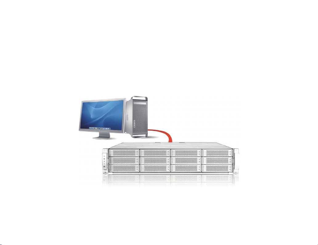
Throughout this guide, the A12S2-PS is installed and congured for a DAS (Direct-Attached Storage) environment.
However, the A12S2-PS can also be easily congured to work in a SAN (Storage Area Net work) environment with
other Accusys equipment, such as the SW04/08.
P2
Quick Start Guide
Page 7
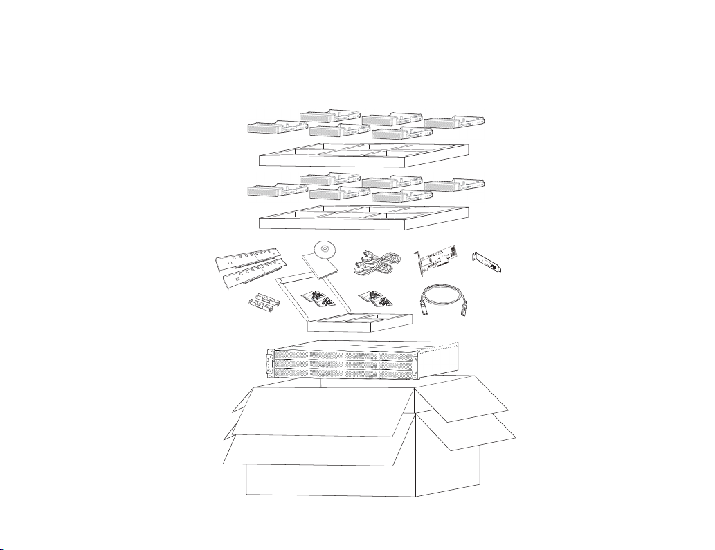
1.1 Checking the Equipment You’ll Need
Below is a complete list of all the equipment you’ll need to set up the ExaSAN A12S2-PS.
Quick Start Guide
Quick Start Guide
P3
Page 8
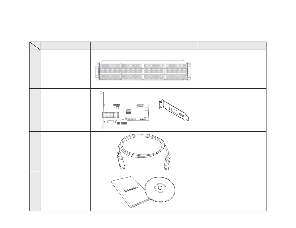
Your ExaSAN A12S2-PS system consists of the standard components listed below. Verify that you have all of the
system components and accessories before commencing hardware installation.
Item Item Image Item Description
PCIe RAID storage
1 A12S2-PS
system, supports R AID
0,1,5,6, 0+1, and JBOD
P4
QSFP Host Bus
2
Adapter &
Half-high bracket
QSFP copper or
3
optical cable
Quick start Guide
4
& Installation CD
20Gb QSFP PCIe HBA ,
supports PCIe 2.0 and 1.1;
1x half-high bracket (for full-
high bracket replacement)
QSFP 2m copper cable,
connects A12S2-PS to
QSFP HBA on host.
Paper of Quick start Guide;
Installation CD includes
some softwares and les
like driver, Boot code,
system code, User Guide
and Quick start Guide.
Page 9
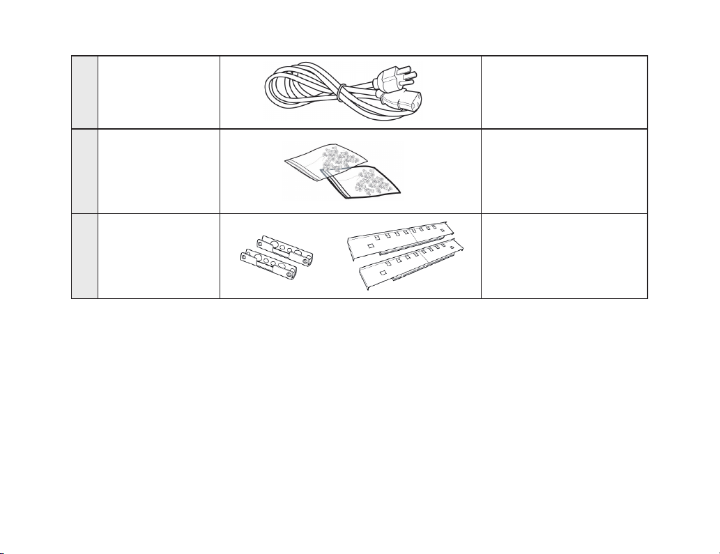
4 Power Cord
2x Power cord for
A12S2-PS
Screw pack for
5
disk tray & rack
6
Additional requirements for the A12S2-PS RAID storage system:
1. Host server requirements:
■
■
■
■
2. Hard drives:
■
■
Quick Start Guide
Rail and rail
extenders
Host server with PCIe 2.0 x4 or above (such as x8, x16 PCIe slot) and CD-ROM drive or network connection
for soft ware and driver installation.
Windows: XP, 2003, Vista, 2008, and Windows 7
MAC: 10.5, 10.6, 10.7 or earlier
Linux: Kernel 2.4 or above, with the necessar y tools installed, such as GCC and XWindow
12x 3.5” hard disk drives (HDD)
A12S2-PS RAID controller supports 6Gb SAS, SATA II drives
2x Screw pack for disk tray
2x Screw pack for rack
Us e d for mo unt i n g th e
A12S2-PS on a rack mount
P5
Page 10
The host server and HDD are not Accusys-supplied equipment and are therefore not included in the package.
Contact your System Integrator/ Value Added Reseller if you need assistance in purchasing these components.
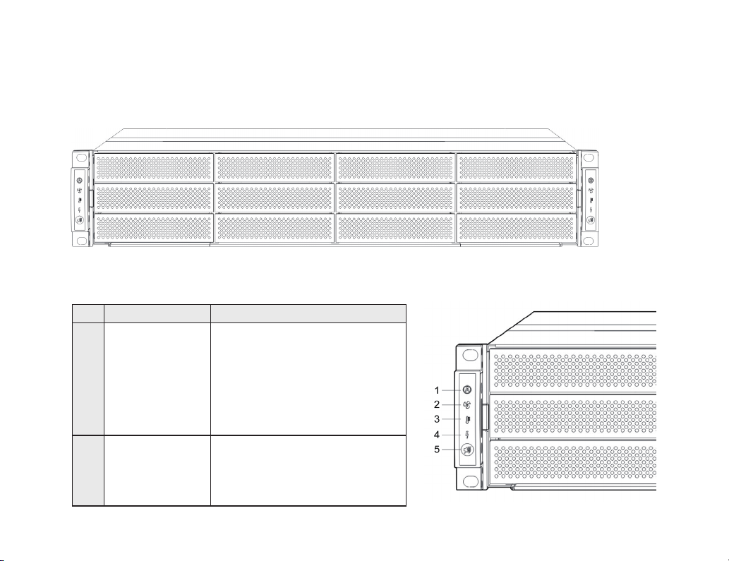
The following gure introduces the front panel of the A12S2-PS.
The following gure and table will help familiarize you with the LEDs on the left side handle of the A12S2-PS
Item Name Description
• Steady Blue indicates the controller
A is working normally.
• Flashing Blue indicates the host is
1 Controller A Status
2 System Fan
accessing.
• Steady Red indicates the controller
A has failed.
• Flashing Red indicates Other error.
• te a dy Bl u e in d i c a t es th e fa n
modules are working normally.
• Steady Red indicates one or more
of the fan modules failed.
Page 11

3 System Temperature
• Steady Blue indicates the system temperature is under the preset value.
• Steady Red indicates the system temperature is over the preset value.
4 System Power
5 Mute Button
The following gure and table introduces the rear panel of the A12S2-PS.
3 4 5 6 7 8
2
1
• Steady Blue indicates the subsystem power supplies are working normally.
• Steady Red indicates that a power supply has failed.
Pushing the button will turn off the system beeper when beeper is sounding.
If another abnormal event occurs, the beeper will sound again.
No. Name Description
1 Power Supply AC In Connects to a power cable and power source.
Quick Start Guide
9
10
11
P7
Page 12

Removable redundant power supply 1
2 Power supply 1
3 Cooling fan 1
4 Heartbeat LED
5 Terminal port Connects to maintenance equipment.
6 PCIe port
7 SAS port
8 Cooling fan 2 Prevents the disk array from overheating.
9 Power supply 2
10 Power Supply AC In Connects to a power cable and power source.
• Steady Green LED indicates the power supply is working normally.
• Steady Red LED indicates the power supply has failed.
Prevents the disk array from overheating.
• Steady Green LED indicates the fan modules are working normally.
• Steady Red LED indicates that a fan module has failed.
Indicates the controller status
• Flashing Green indicates the controller is active
• LED is off if controller is inactive.
Connects the controller to the HBA on the host ser ver.
• Host connected LED (top): Steady Green indicates the controller is connected normally.
• Host access LED (bottom): Flashing Blue indicates host accessing is in progress
Expansion port for SAS JBOD.
• JBOD connected LED (top): Steady Green indicates that JBOD is connected normally.
• JBOD access LED (bottom): Flashing Blue indicates controller accessing is in progress
Removable redundant power supply 2
• Steady Green LED indicates the power supply is working normally.
• Steady Red LED indicates the power supply has failed.
11 Power supply switch Switches the power on or off.
Page 13

1.2 Understanding the Installation Steps
Step 1 Unpacking the storage package
Step 2 Installing Disk Drives, refer to the A12S2-PS User Manual for instructions
Step 3 Installing QSFP HBA
Step 4 Connecting R AID to the Host system
Step 5 Powering the System On
Step 6 Install RAIDGuard X
Step 7 Array Conguration
Step 8 Formatting and Mount Array
1.3 Setting up the Hardware
1.3.1 Installing the HBA Card
Before the ExaSAN A12S2-PS is ready to be connected and powered on, you must install the HBA card in the
workgroup client system. The HBA card is compatible with PCIe x4, x8, and x16 slots. If a choice is given, use the
fastest PCIe slot available. Although the HBA card is compatible with both PCIe 1.1 and 2.0 standards, only the
latter is recommended due to performance consideration.
Caution:
PCIe slots on some motherboards are for graphics cards only.
Check with the motherboard vendor for compatibility.
Quick Start Guide
P9
Page 14

Follow these steps to install the card in each host system:
1. Make sure that the client system is turned off.
2. Open the client system’s outer casing cover, check with
your vendor documentation for instructions if necessary.
3. Re-position the HBA card so that you are facing jumper
switch as shown below. You can use the jumper switch to
congure the HBA for DAS or SAN usage. Set the jumper
switch before installing into the host.
* DAS mode: When the switch is in the "On” position, the
HBA card is enabled for RAID (Direct-Attached Storage
A12S2-PS) mode.
* SAN mode: In the “1” position, the HBA is enabled for
switch (SAN) mode.
4. Locate the available PCIe slot. Remove the blank plate if
one is present and save the screw for later use.
5. Position the connector of the card over the slot and then
insert the connector into the slot. Press gently but firmly
until it is securely seated.
P10
Page 15

6. Use the screw that you saved in step 2 to secure
the metal bracket of the card to the system case.
7. Replace the outer casing cover.
1.3.2 Connecting the HBA to the A12S2-PS System
1. Befo re the E xaSAN A12S2- PS is ready to b e
connected and powered on, you must install the
HBA c ard in the workgr ou p client system. The
HBA card is compatible with PCIe x4, x8, and x16
slots. If a choice is given, use the fastest PCIe slot
available. Although the HBA card is compatible
with both PCIe 1.1 and 2.0 st andards, o nly t he
la t te r is re c om m e n d e d due to per f o r ma n c e
consideration.
Quick Start Guide
P11
Page 16

2. Insert the other end of the cable into the PCIe port on the HBA card,
which you installed on the host system in the earlier section. The cable
connector is securely plugged when you hear a click.
3. Plug a power cord into the AC power-in port in the storage system.
Caution
Once powered on, Do NOT remove the QSFP PCIe cable when in
use to avoid data loss and corruption.
P12
Quick Start Guide
Page 17

1.4 Powering On and Off the A12S2-PS
1.4.1 Powering On
Before powering on the A12S2-PS, make sure that all cables and cords are properly installed and connected.
1. Turn power on for the A12S2-PS by switching on the Power button. Wait for the Controller A status (refer to the
gure on A12S2-PS Front Panel LEDs) to turn into a steady blue state. Note that you might hear a few short
beeps generated from the RAID disk system during this process. You may ignore them as they are designed for
Accusys’ internal diagnostic purpose only.
2. Turn on the host server.
Caution
It is important to follow the correct Power On sequence. Failure to
do so may result in some features not functioning properly.
1.4.2 Powering Off
If you need to power off the entire system, such as in the cases of switch or RAID system rmware updates, adding
a RAID system or client computer, power off in the following sequence.
1. Turn off the host server rst. During RAID initiation or disk drive rebuilding, you can turn off the host server and
leave the A12S2-PS powered on.
2. Power of f the A12S2-PS RAID System by turning off the power switch.
Quick Start Guide
P13
Page 18

P14
Quick Start Guide
Page 19

2
Software Installation
and Conguration
Quick Start Guide
P15
Page 20

2. RAIDGuard X Introduction
RAIDGuard X is a powerful tool which supports remote monitoring of multiple controllers that are connected to the
same network. It is to be used in conjunction with Accusys PCIe series.
The software comes with 2 components: Server and Client.
Server – Enables the server to recognize the RAID controller(s).
Client – The Client software can be installed on any computer that needs to administer the controller(s).
The Client sof tware works on any c omputer running JAVA 1.6 or above and is used to administer the RAID
controller(s). It contains all the functionality needed to congure and administer RAID arrays. Use the software to:
• Add and delete arrays
• Fix problems with disks
• Manage the arrays and disks
• Set audio and e-mail alerts
• Monitor the status of multiple controllers
2.1 Installing the driver and RAIDGuard X
The RAIDGuard X GUI can be installed from the CD-ROM supplied with the ExaSAN R AID system. If you can't
nd the CD-ROM or wish to install the latest version of the software, go to http://www.accusys.com.tw/support /
download_new.htm for available downloads.
The Quick Start Guide covers the software installation for PCs and Macs. For driver and RAIDGuard X installation
on Linux systems, consult the A12S2-PS User Guide.
P16
Quick Start Guide
Page 21

1. Insert the CD-ROM into the CD-ROM drive of the MAC or PC.
2. For Macs, execute “CD-ROM/MAC Installation/Vx.x/6xxxx_IP_MAC_x_x_x.mpkg".
For PCs, execute “CD-ROM/ Windows installation/GUI/x.x/6xxx_IP_Win_x.x.exe”.
If you have downloaded the installer from the Accusys support page, look in your download path for the installer le.
3. Follow the onscreen instructions. Sample screens shown below are from a MAC installation.
4. Acce pt the Licen se
Agreement and click
Continue.
Quick Start Guide
P17
Page 22

5. Select the Destination volume from the list
of available options to install R AIDGuard X.
Click Continue after making your selection.
6. Click Install to continue with the Standard
installation, which will automatically install
the Driver, the R AIDGuard X Ser ver, and
the RAIDGuard X Client
7. Cli c k to Restar t th e co m put e r a f t er t h e
installation is complete.
Before you can access the RAID controller, you must rst load the RAIDGuard X software.
To access RAIDGuard X Client:
Macs: Go -> Application -> RAIDGuard X -> RAIDGuard X Client
Windows: Start -> Program -> Accusys -> RAIDGuard X -> RAIDGuard X Client
To access RAIDGuard X Server:
Macs: Go -> Application -> RAIDGuard X -> RAIDGuard X Server
Windows: Start -> Program -> Accusys -> RAIDGuard X -> RAIDGuard X Server
The gure below introduces the RAIDGuard X Main screen.
P18
Quick Start Guide
Page 23

P19
Page 24

2.2 Array Configuration
In order to create an array, the RAID controller rst needs to be added to the network.
Follow the steps below to add a controller in RAIDGuard X:
1. Click Add Controller to display a list of available controllers on the network. If the ExaSAN RAID system is used
as a DAS, the controller is displayed as “Local” under the IP eld.
2. C li c k on t he c o nt r o ll e r t o
administer, enter the password.
Th e def ault pas s w ord for the
Ac c u s y s PC Ie co n t r o ll ers is
00000000 (8 zeros).
3. Assign a name to the controller
and click Add.
P20
Quick Start Guide
Page 25

4. The Main screen lists the controller after it has been successfully added.
After the R AID controller is congured, an array can be created. This array tells the controller how many disks to
use and what their function should be.
Follow the steps below to create an array:
1. Select the R AID level from the drop down menu. Available levels are: 0, 1, 5, 6, 0+1 and JBOD.
Note
Each RAID level has a minimum disk requirement. This is shown in the information
to the right of the drop down list. For example, RAID 5 requires at least 3 drives.
Quick Start Guide
P21
Page 26

2. Select the stripe size from the drop down menu. Available stripe sizes are: 8-256KB. The greater the stripe size,
the faster the I/O output for each drive. This speeds up disk access.
3. Select the sector size from the drop down menu. Available sector sizes are 512 bytes (default) and 4096 bytes.
The sector size 4096 bytes is only supported by Windows 2000/XP, and over 2 Terabyte function is used. For
other OSes, please select 512 bytes (default).
4. Click on the drives to be added to the array. You can also click on Select all spare drivers.
Note
Hot (Global) spare drive – When building an array, the hard drives which are not defined
will be used as spare drives for all arrays defined within the controller. If a drive(s) in use
fails, a spare drive(s) will replace the faulty drive in the array and rebuild automatically.
One of the advantages of adopting hot spare drive is to reduce the downtime.
P22
Quick Start Guide
Page 27

Optional: From the drop down menu, select On-the-y initialization. For a detailed explanation on the Initialization
type, consult the A12S2-PS User Guide.
5. Check the Assign LUN automatically box.
6. Click Create Array to complete the process.
Note
If you attempt to create a RAID set without meeting the minimum required number
of hard disk drives, an error message will pop up after clicking Create Array.
Quick Start Guide
P23
Page 28

After the array has been created, the Main screen displays the newly created array with an array number. The
array initialization progress is also displayed.
Arrays are assigned numbers in the order they are created. For example, the rst array created is labeled with the “1”
icon; the second array created is labeled with the “2” icon, and so for th.
2.3 Formatting and Mounting Arrays
After creating a R AID array on the ExaSAN RAID system, the array appears as an unformatted disk to the host
system. Use the host's disk management utility to format and mount the array for use.
Note
The following steps are for mac users only. For PC users, consult with your
operating systems knowledge base on using the disk management utility
to format and mount arrays.
1. Restar t the host system. In some instances, restar ting the host system may not be necessary, but if you are
creating or adding arrays, you generally must restart before the arrays are visible in Disk Utility.
2. Open Disk Utility on the host system.
3. Select the array in the list at the left side of the window.
4. Click on the Erase tab.
5. Choose a format for the array from the Volume Format pop-up menu.
6. Type a name for the array.
7. Click Erase and conrm by clicking Erase again. Once formatting is complete, the array mounts on the host
system.
8. Repeat for each new array.
P24
Quick Start Guide
Page 29

2.4 Contact Us
5F, No.38, Taiyuan St, Jhubei City, Hsinchu Country 30265, Taiwan R.O.C.
TEL: +886-3 -560-0288 FAX: +886-3-560- 0299
WEB: www.accusys.com.tw
SALES: sales@accusys.com.tw
For customer services and technical support, locate an Accusys ofce near you from the link below:
http://www.accusys.com.tw/about/contact.htm
or, you may e-mail us at: support@accusys.com.tw
2.5 Trouble shooting
Q: RAIDGUard X unable to see any A12S2-PS
A: Please check the Link status on QSFP card, if the LED shown orange and then must change the jumper switch
as ON.
Quick Start Guide
P25
Page 30

Quick Start Guide
Page 31

Page 32

42-33000-5042
 Loading...