

Page 1
A16R-SJ Quick Start Guide
ExaRAID JBOD SYSTEM
USER'S GUIDE
A12/16/24R/U-SJ
Quick Start Guide
1
Page 2
A16R-SJ Quick Start Guide
A12/16/24R/U-SJ
Quick Start Guide
42-33000-5030
ExaRAID JBOD SYSTEM
Version:1.2
1
Page 3
A16R-SJ JBOD Task List
Quick Start Guide
1
2
3
4
5
6
8
9
10
11
12
7
Step 1: Unpacking the JBOD System below
Step 2: Mounting the JBOD System in a Rack on page 10
Step 3: Installing Disk Drives on page 14
Step 4: Making Connections on page 18
Step 5: Powering on the System on page 21
on page 22
on page 28
Step 8: Powering Off the System on page 30
JBOD System Quick Start Guide
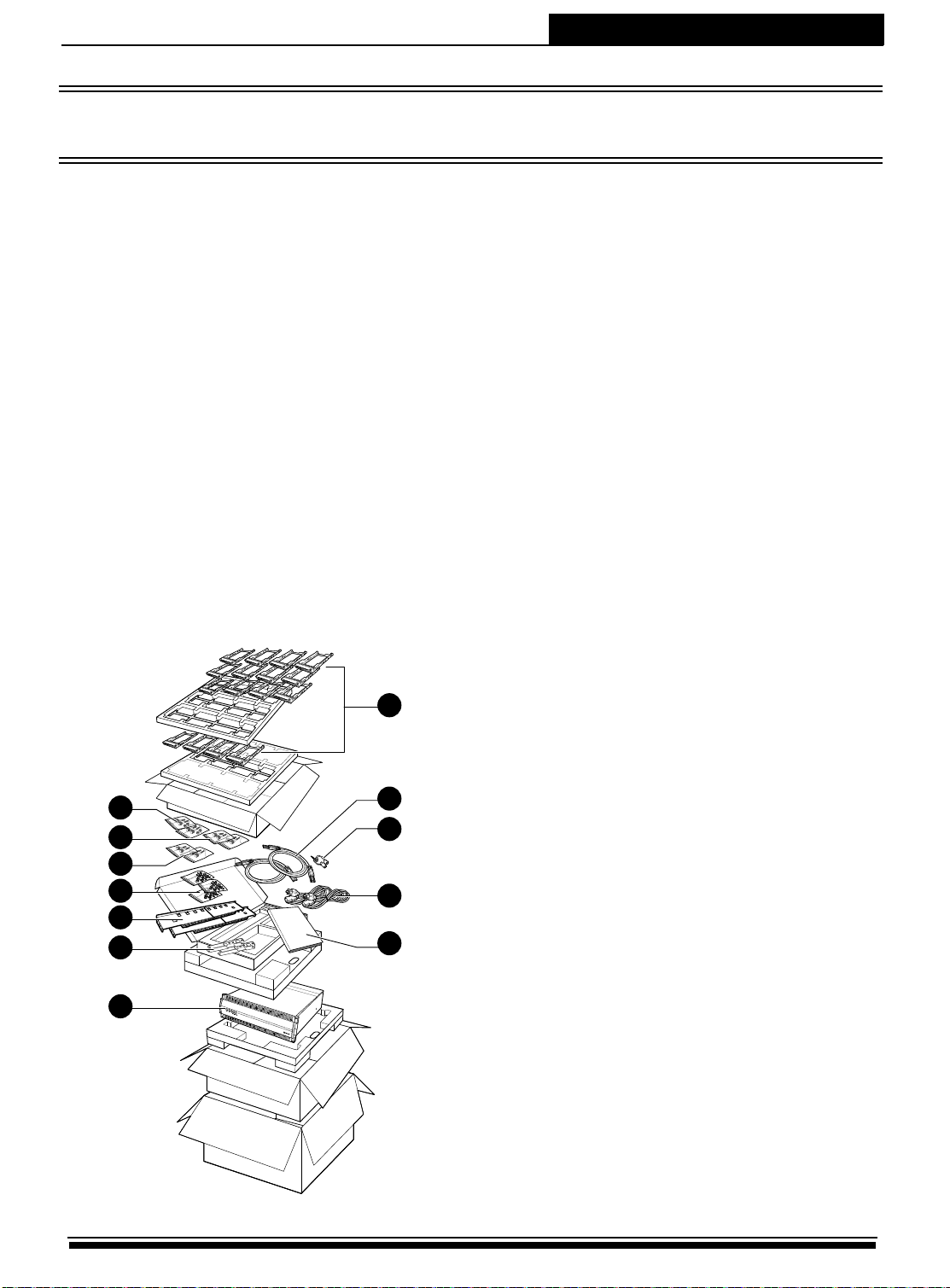
Step 1: Unpacking the JBOD System
The following items come with the JBOD system package, if any of them
is missing or damaged, please contact your supplier:
1. Hard disk tray: A12R/U-SJ x 12
A16R/U-SJ x 16
A24R/U-SJ x 24
2. SAS cable: A12/A16/A24U-SJ x 1
A12/A16/A24R-SJ x 2
3. Front panel key x 2
4. Power cable: A12/A16R/U-SJ x 2
A24R/U-SJ x 3
5. Quick Start Guide
6. M5 fix screw x 2 packs
7. M6 fix screw x 2 packs
8. UNC #10-32 fix screw x 2 packs
9. HDD screw x 3 packs
10. Rail x 1 set
11. Rail extender x 1 set
12. JBOD system
1
Page 4
JBOD System Quick Start Guide
P
o
w
er
IO
#
2 A
C
T
IO
#
1
A
C
T
IO
#
2 R
D
Y
IO
#
1 R
D
Y
H
D
D
Te
m
p
F
a
n
Power
IO#2 ACT
IO#1 ACT
IO#2 RDY
IO#1 RDY
HDD
Temp
Fan
2 6 81 3 4 5 7
9
A12R/U-SJ
A16R/U-SJ
A24R/U-SJ
Front Panel View (Closed)
2 6 81 3 4 5 7
Power
HDD
Temp
Fan
Power
Temp
Fan
2 6 81 3 4 5 7
Power
HDD
Temp
Fan
P
T
F
a
e
o
n
w
e
r
HDD
H
m
p
IO#1 RDY
IO#1 RDY
IO#1 RDY
I
O
D
#
D
1
IO#2 RDY
IO#2 RDY
IO#2 RDY
I
O
#
2
R
D
Y
IO#2 ACT
IO#1 ACT
9
IO#2 ACT
IO#1 ACT
IO#1 ACT
IO#2 ACT
9
I
I
O
O
#
#
2
1
A
A
R
C
C
D
Y
T
T
No. Item Description
• Green - Power supplies are installed and
working properly.
1 Power LED
• Red - The JBOD system has a faulty power
supply.
2
Page 5

JBOD System Quick Start Guide
No. Item Description
• Green - Fan modules are installed and
working properly.
2 Fan LED
• Red - The JBOD system has a faulty fan
module.
• Green - The JBOD system temperature is
below 55ºC.
3 Temp LED
• Red - The JBOD system temperature
exceeds 55ºC.
• Green - All installed disks are working
properly.
4 HDD LED
• Red - The JBOD system has a faulty hard
disk.
5 IO#1 RDY Indicates JBOD controller A is working properly.
6 IO#2 RDY Indicates JBOD controller B is working properly.
7 IO#1 ACT
8 IO#2 ACT
9 Lock Locks the front cover
Indicates data activity in progress between host
and JBOD controller A.
Indicates data activity in progress between host
and JBOD controller B.
3
Page 6
JBOD System Quick Start Guide
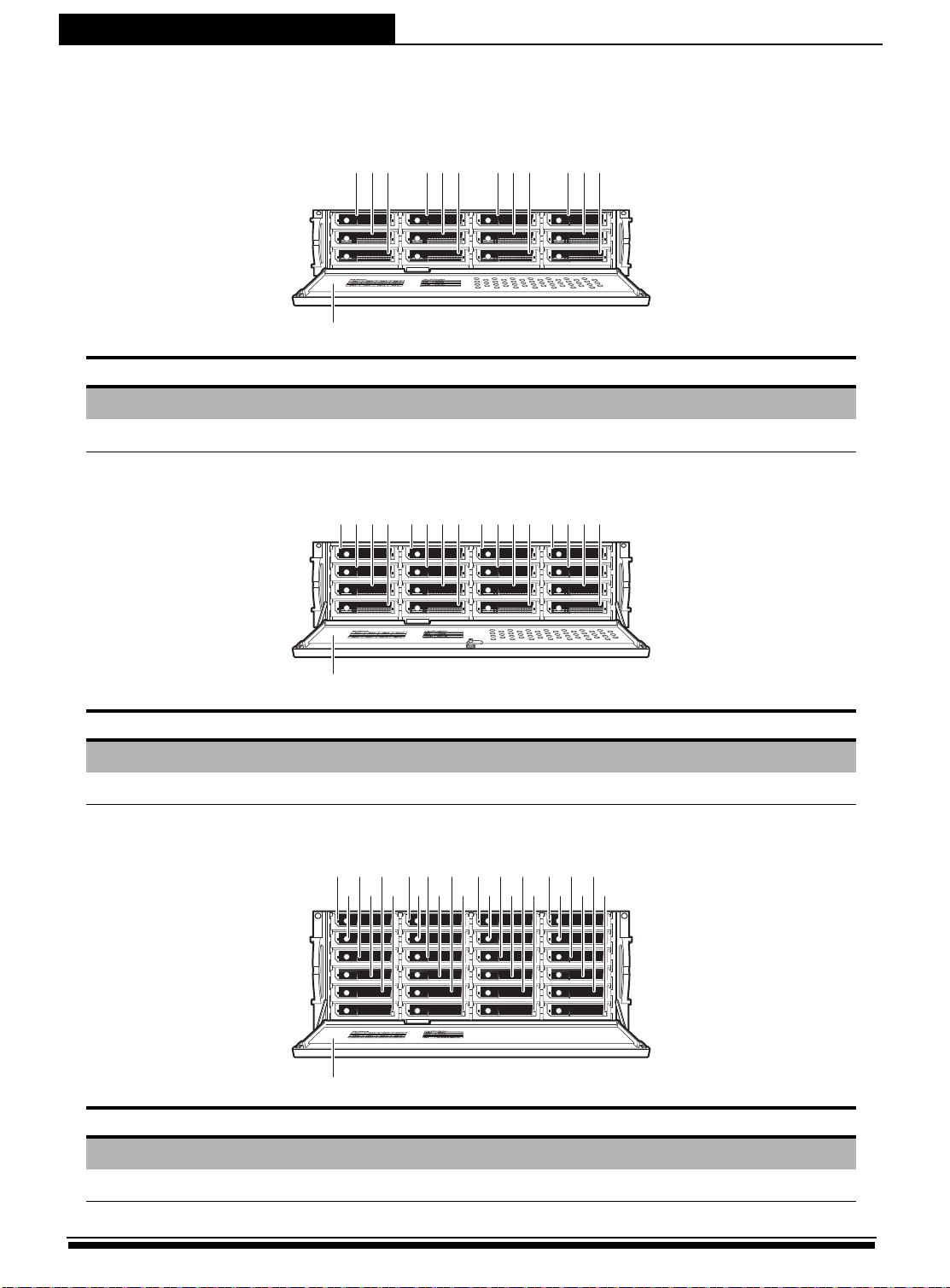
Front Panel View (Open)
A12R/U-SJ
13
No. Item Description
1 2 3 4 5 6 7 8 9 10 11 12
1-12
13
Disk trays 12 Removal disk trays.
Front panel door Protects the disks.
A16R/U-SJ
1172 3 4 5 6 7 8 9 10 11 12 13 14 15 16
No. Item Description
1-16
17
Disk trays 16 Removal disk trays.
Front panel door Protects the disks.
A24R/U-SJ
1
23456789101112131415161718192021222324
25
No. Item Description
1-24
25
4
Disk trays 24 Removal disk trays.
Front panel door Protects the disks.
Page 7
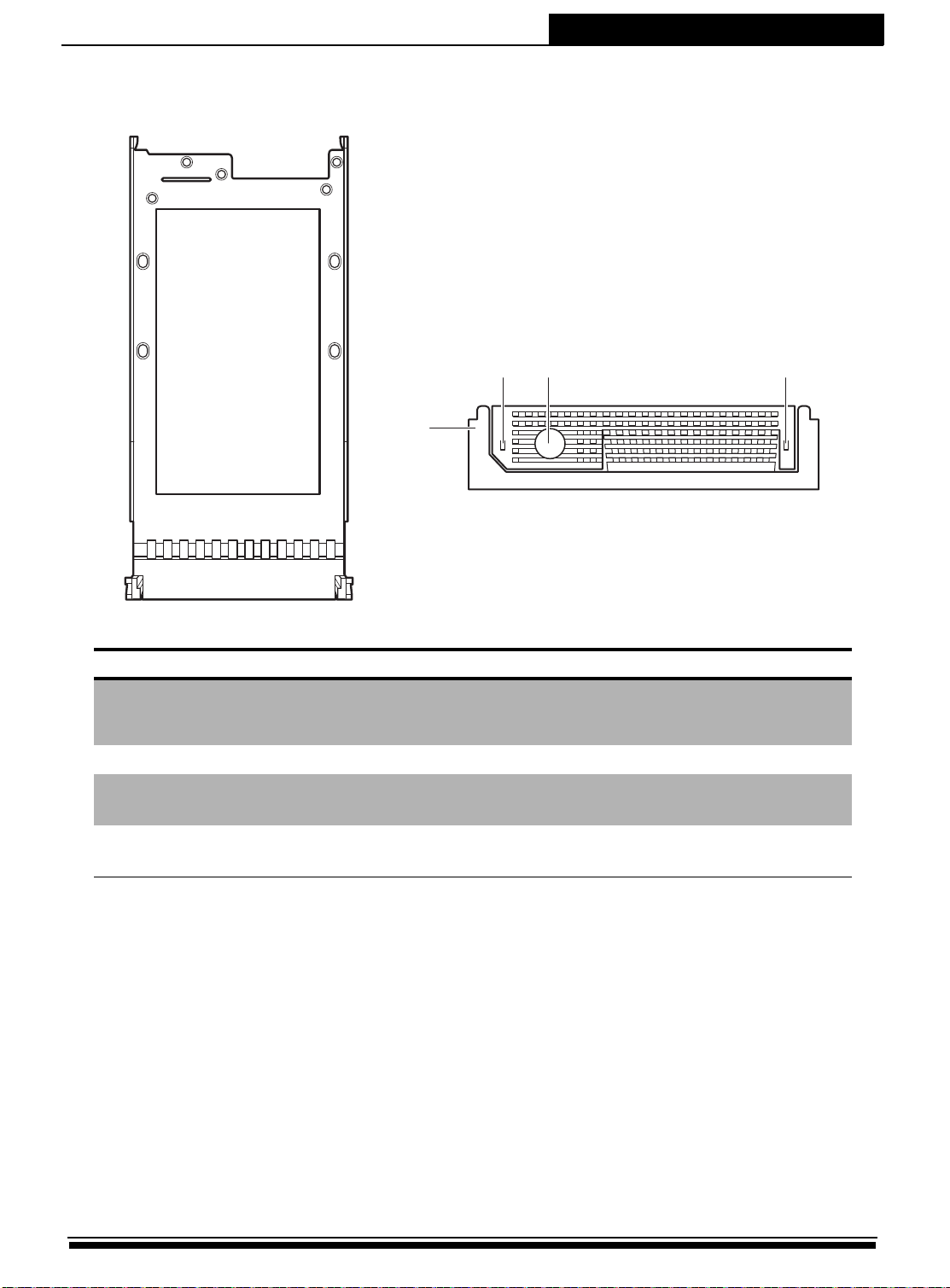
Disk Tray
13 2
4
Front View
JBOD System Quick Start Guide
No. Item Description
• Green - Disk is online
1 Disk LED
• Red - No disk or disk fail
2 Tray button Press to release the tray handle.
3 Access LED indicator
4 Tray handle
Lights blue when the disk is being
accessed.
Use to pull out or lock the disk tray into
place.
5
Page 8
JBOD System Quick Start Guide
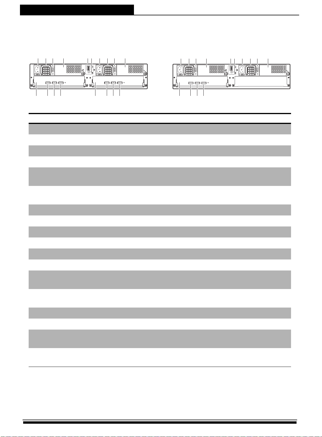
A12R-SJ A12U-SJ
Rear View
1
2 3 4 75 6
1
EXP CH 1 CH 2 EXP CH 1 CH 2
A
15
432
U
P
S
ON DIP
8 9 10
1
2 3 4 75 6 8 9 10
ON DIP
15
2
B
1
EXP CH 1 CH 2
A
432
U
P
S
2
B
12 13 14 16 17 1811
15
12 13 1411
No. Item Description
1
2
3
4
5
6
7
8
9
10
11
12
AC power port Connects to the power source.
Power supply handle Use to pull out the power supply.
Power supply switch Use to switch the power on or off.
Cooling fan 1 System cooling fan.
Chassis ID
UPS port
Use for JBOD enclosure only, See Switch
ID on page 9.
Data port for uninterruptable power
supply.
AC power port Connects to the power source.
Power supply handle Use to pull out the power supply.
Power supply switch Use to switch the power on or off.
Cooling fan 2 System cooling fan.
JBOD Controller A JBOD controller.
Expansion port (Controller A) Use for JBOD expansion.
13
14
15
16
17
18
Host channel 1 (Controller A)
Host channel 2 (Controller A)
JBOD Controller B JBOD controller.
Expansion port (Controller B) Use for JBOD expansion.
Host channel 1 (Controller B)
Host channel 2 (Controller B)
Connects to EXP port on RAID system or
SAS HBA card of host.
Connects to EXP port on RAID system or
SAS HBA card of host.
Connects to EXP port on RAID system or
SAS HBA card of host.
Connects to EXP port on RAID system or
SAS HBA card of host.
6
Page 9
JBOD System Quick Start Guide
EXP CH 1 CH 2 EXP CH 1 CH 2
Fan 1 Fan 3
Contraller A
Fan 2
Contraller B
P/S 1 P/S 2
VER 1.0
P/S
UPS
Chassis
ID
5
6
7
8
9
0
1
2
3
4
1 6
13 14 15 16 17 1812 20 2119
2 543 1098 117
EXP CH 1 CH 2
Fan 1 Fan 3
Contraller A
Fan 2
Contraller B
P/S 1 P/S 2
VER 1.0
P/S
UPS
Chassis
ID
5
6
7
8
9
0
1
2
3
4
1 6
13 14 15 16 17 1812 20 2119
2 543
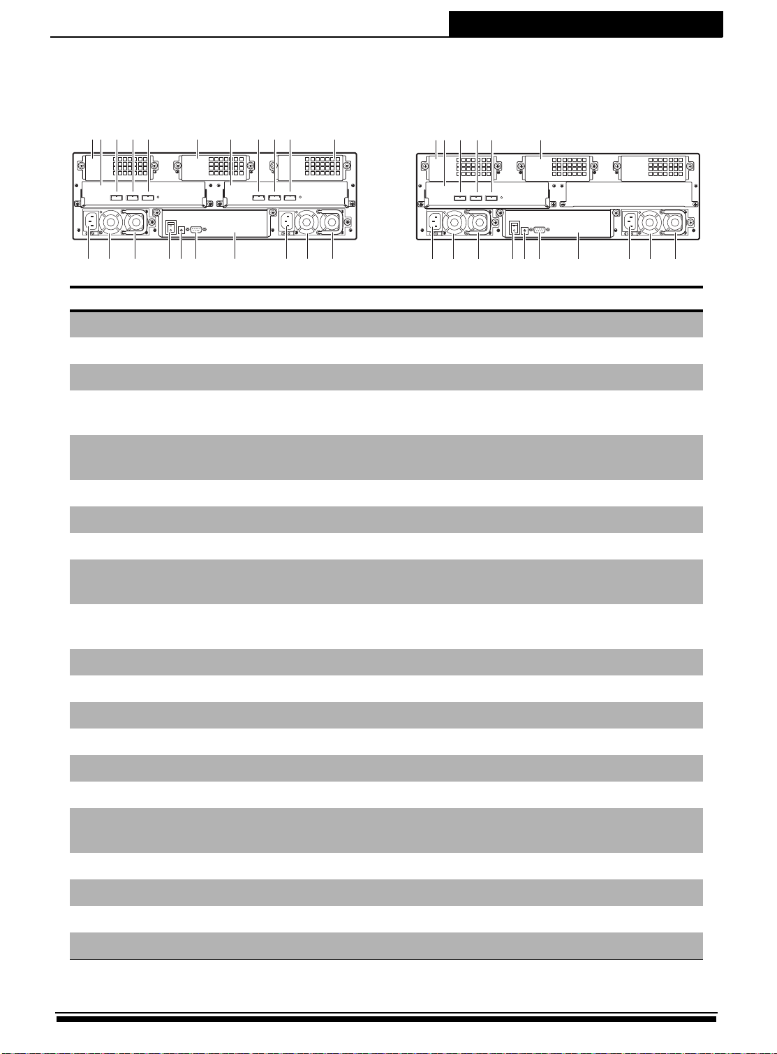
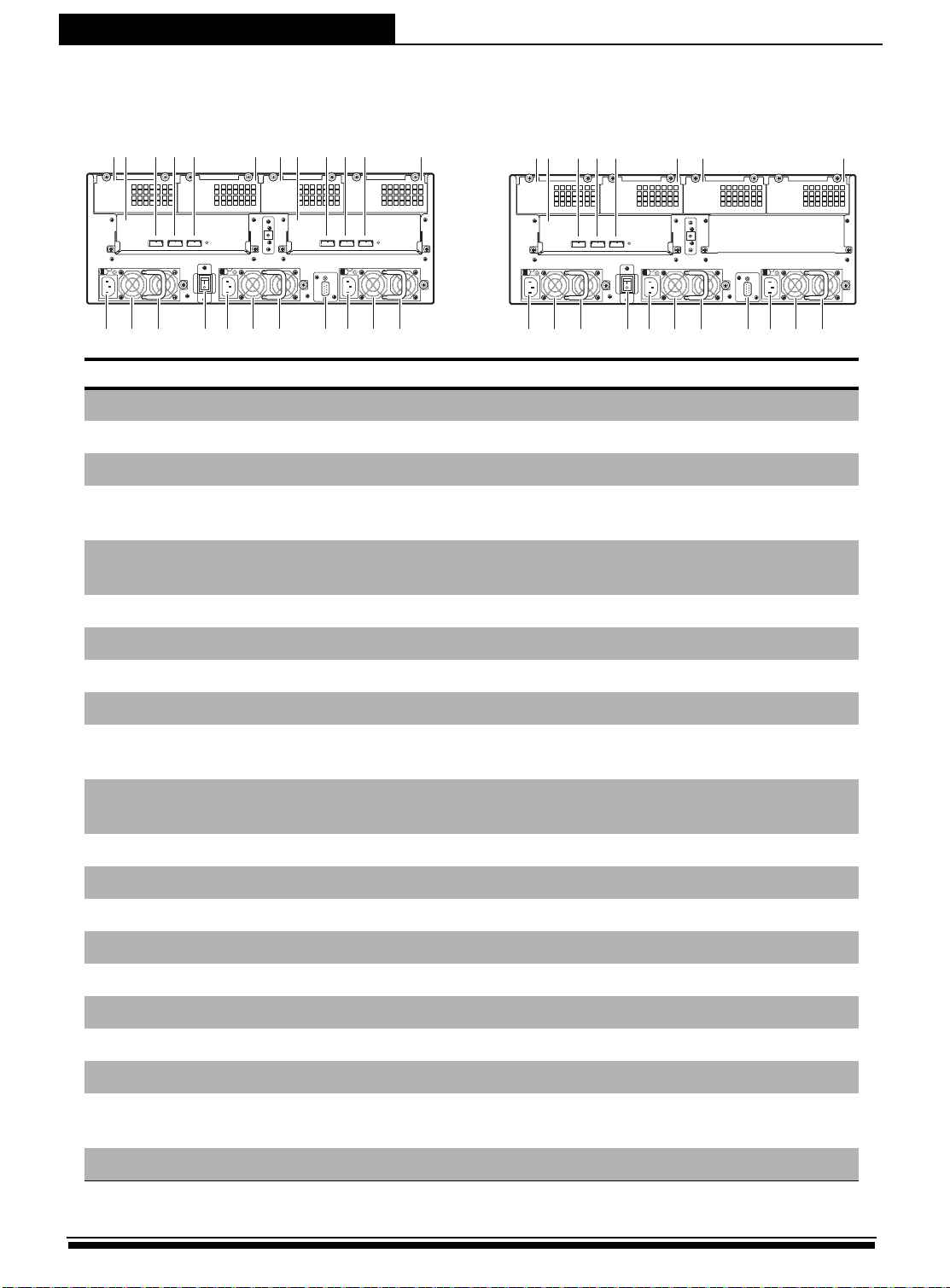
A16R-SJ A16U-SJ
No. Item Description
1
Cooling fan 1 System cooling fan.
2
JBOD Controller A JBOD controller.
3
Expansion port (Controller A) Use for JBOD expansion.
4
5
6
7
8
9
10
11
12
13
14
15
16
Host channel 1 (Controller A)
Host channel 2 (Controller A)
Connects to EXP port on RAID system or
SAS HBA card of host.
Connects to EXP port on RAID system or
SAS HBA card of host.
Cooling fan 3 System cooling fan.
JBOD Controller B JBOD controller.
Expansion port (Controller B) Use for JBOD expansion.
Host channel 1 (Controller B)
Host channel 2 (Controller B)
Connects to EXP port on RAID system or
SAS HBA card of host.
Connects to EXP port on RAID system or
SAS HBA card of host.
Cooling fan 2 System cooling fan.
AC power port Connects to the power source.
Power supply 1 Removable power supply.
Power supply handle Use to pull out the power supply.
Power supply switch Use to switch the power on or off.
Chasis ID switch Use for JBOD enclosure only.
17
18
UPS port
IO tray Holds the IO board and BBMs.
Data port for uninterruptable power
supply.
19
20
21
AC power port Connects to the power source.
Power supply 2 Removable power supply.
Power supply handle Use to pull out the power supply.
7
Page 10
JBOD System Quick Start Guide
A24R-SJ A24U-SJ
1 62 3 4 5 9 10 117 128
Fan 1 Fan 3 Fan 4 Fan 2Fan 1
3
2
4
1
5
0
6
9
7
EXP CH 1 CH 2 EXP CH 1 CH 2
Contraller A Contraller B
P/S 1 P/S 3 P/S 2
14 15 1613 18 1917 20 22 2321
8
Chassis ID
UPS
1 62 3 4 5 7 12
Fan 1 Fan 3 Fan 4 Fan 2Fan 1
3
2
4
1
5
0
6
9
7
EXP CH 1 CH 2
Contraller A Contraller B
P/S 1 P/S 3 P/S 2
14 15 1613 18 1917 20 22 2321
8
Chassis ID
No. Item Description
1
2
3
4
5
6
7
Cooling fan 1 System cooling fan.
JBOD Controller A JBOD controller.
Expansion port (Controller A) Use for JBOD expansion.
Host channel 1 (Controller A)
Host channel 2 (Controller A)
Connects to EXP port on RAID system or
SAS HBA card of host.
Connects to EXP port on RAID system or
SAS HBA card of host.
Cooling fan 3 System cooling fan.
Cooling fan 4 System cooling fan.
UPS
8
9
10
11
12
13
14
15
16
17
18
19
20
21
JBOD Controller B JBOD controller.
Expansion port (Controller B) Use for JBOD expansion.
Host channel 1 (Controller B)
Host channel 2 (Controller B)
Connects to EXP port on RAID system or
SAS HBA card of host.
Connects to EXP port on RAID system or
SAS HBA card of host.
Cooling fan 2 System cooling fan.
AC power port Connects to the power source.
Power supply 1 Removable power supply.
Power supply handle Use to pull out the power supply.
Power supply switch Use to switch the power on or off.
AC power port Connects to the power source.
Power supply 3 Removable power supply.
Power supply handle Use to pull out the power supply.
UPS port
Data port for uninterruptable power
supply.
AC power port Connects to the power source.
8
Page 11
JBOD System Quick Start Guide
1
ID12ID23ID34ID45ID5
ON(1)
OFF(0)
No. Item Description
22
23
Power supply 2 Removable power supply.
Power supply handle Use to pull out the power supply.
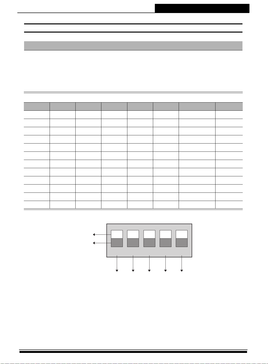
Switch ID
See table below on how to set the Chassis ID.
2U-12R/U Chassis ID
ID1(A3) ID2(A2) ID3(A1) ID4(A0) ID5
02G
14G
0000 0
0001 1
0010 2
0011 3
0100 4
0101 5
0110 6
Chassis ID
FC-HDD Speed Remark
0111 7
1000 8 N/A
1001 9 N/A
9
Page 12

JBOD System Quick Start Guide
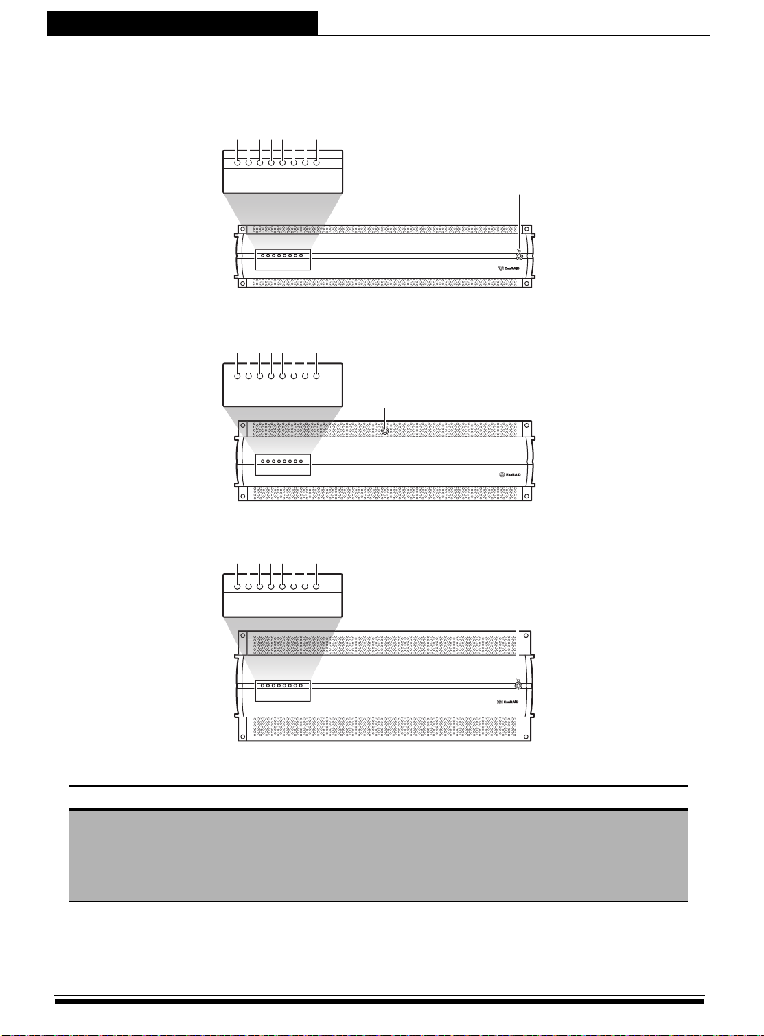
Step 2: Mounting the JBOD System in a Rack
The JBOD system can be installed in a standard 19-inch rack. Follow the
procedures below:
1.Attack eight rack nuts into the rack, making sure that they correspond with the mounting points on the rails.
2.Adjust the length of the rails as needed.
3.Secure the rails using two nuts and bolts on both the front and back posts of the rack.
4.Tighten the locking screws.
5.Slide the JBOD system into the rack and secure it into place using the fixing screws.
P
I
IO
IO
IO
H
T
F
O
a
e
o
D
#
#
#
#
n
m
w
D
2
1
2
1
e
p
R
A
A
R
r
C
C
D
D
Y
Y
T
T
10
Page 13

JBOD System Quick Start Guide
Using the Rail Extenders
Follow the procedures below to install the rail extenders:
1.Install the rail extenders and attach the screws to secure them.
2.Slide the RAID system into the rack and secure it into place using the fixing screws.
P
IO
I
IO
I
H
T
F
O
O
a
e
o
D
#
#
#
#
n
m
w
D
1
2
1
2
e
p
A
A
R
R
r
C
C
D
D
Y
Y
T
T
Rack-Mount Instruction
follow these instructions:
1. Place the “A12R/U-SJ, A16R/U-SJ and A24R/U-SJ” on a hard flat
surface with the front panel facing you.
2. Attach a rack–mount bracket to one side of the “A12R/U-SJ,
A16R/U-SJ and A24R/U-SJ” with the supplied screws. Then attach the
other bracket to the other side.
To mount the “A12R/U-SJ, A16R/U-SJ and A24R/U-SJ” in any standard-sized rack,
3. Make sure the brackets are properly attached to the “A12R/U-SJ,
A16R/U-SJ and A24R/U-SJ”.
11
Page 14

JBOD System Quick Start Guide
Make sure you use the screws sup plied with the mou nting brackets. U sing the wrong screws
could dam age the “A12R/U-SJ, A16R/U-SJ and A24 R/U-SJ” an d w ould invalidate your
wa rran ty.
4. Use the appropriate screws (not included) to securely attach the
brackets to your rack.
5. Elevated Operating Ambient - If installed in a closed or multi-unit rack
assembly, the operating ambient temperature of the rack environment may
be greater than room ambient. Therefore, consideration should be given to
installing the equipment in an environment compatible with the maximum
ambient temperature(Tma) specified by the manufacturer.
6. Reduced Air Flow - Installation of the equipment in a rack should be
such that the amount of air flow required for safe operation of the
equipment is not compromised.
7. Mechanical Loading - Mounting of the equipment in the rack should
be such that a hazardous condition is not achieved due to uneven
mechanical loading.
8. Circuit Overloading - Consideration should be given to the connection
of the equipment to the supply circuit and the effect that overloading
of the circuits might have on overcurrent protection and supply wiring.
Appropriate consideration of equipment nameplate ratings should be used
when addressing this concern.
9. Reliable Earthing - Reliable earthing of rack-mounted equipment should be
maintained. Particular attention should be given to supply connections
other than direct connections to the branch circuit (e.g. use of power strips).
12
Page 15

JBOD System Quick Start Guide
Caution
Slide/raid mounted equipment is not to be used as a shelf or a work
spac.
13
Page 16

JBOD System Quick Start Guide
A16R-SJ A12R-SJ / A24R-SJ
Step 3: Installing Disk Drives
The JBOD system supportS SAS or SATA interface hard drives.
SAS hard disks
Follow the procedures below to install SAS hard drives:
1.Insert the SAS hard drive into the hard disk tray. Screw the sides to secure the hard disk. Repeat this procedure to install more hard disks.
2.Insert the key to the key slot and turn to unlock the front panel door.
220
0
2
2
220
3.Pull open the front panel door.
14
Page 17

JBOD System Quick Start Guide
4.Insert the hard disk tray into the empty slot.
5.Push down the tray handle to secure the hard disk tray into place.
6.Repeat steps 4 to 5 until all the required disks have been installed.
7.Close the front panel door, then lock it.
15
Page 18

JBOD System Quick Start Guide
SATA hard disks
SATA hard drive installation requires an AA-MUX adapter to be installed
on the hard disk tray first before installing the SATA hard disk.
Note
AA-MUX is an optional accessory and is sold separately. Contact your
supplier to purchase one.
Follow the procedures below to install SATA hard disks:
1.Place the AA-MUX adapter on the hard disk tray and attach the four screws as shown.
2.Place the hard disk into the hard disk tray with the drive connectors facing the AA-MUX adapter.
16
Page 19

JBOD System Quick Start Guide
3.Slide the hard disk towards the AA-MUX adapter and connect the power and data connectors.
4.Attach the screws to secure the hard disk.
5.Insert the hard disk tray into an empty slot.
6.Push down the tray handle to secure the hard disk tray into place.
7.Repeat steps 1 to 6 until all the required disks have been installed.
8.Close the front panel door, then lock it.
17
Page 20

JBOD System Quick Start Guide
HBA card of host server
RAID system connection. A16R-FS
Fibre RAID system is shown above.
Step 4: Making Connections
The JBOD system has two controllers, each controller has three x4 SAS
ports that enables you to connect to a host computer, a RAID system or
expand the JBOD enclosure.
Use a x4 SAS cable to connect the JBOD system to a host computer or to
a RAID system. Follow the procedures below:
1.Insert the SAS cable into the CH1 port of A16R-SJ.
A
2.To connect to a RAID system, insert the other end of the SAS cable to the EXP port of the RAID system(B). Or to connect to a host server, insert the other end of the SAS cable to the HBA connector of the host server (C).
B
C
Note
To configure, see .
18
Page 21

JBOD System Quick Start Guide
Figure 1-1 RAID system with JBOD enclosure in a loop
A16R-FS/ A16R-SS (RAID)
Chassis ID = 0
A16R-SJ (JBOD1)
Chassis ID = 1
A16R-SJ (JBOD2)
Chassis ID = 2
A16R-SJ (JBOD3)
Chassis ID = 3
Expanding JBOD Enclosures
You can expand a maximum of seven JBOD enclosures to a RAID system.
Figure 1-1 shows a RAID system with three JBOD enclosures in a loop. The
loop connection works to ensure the system can continue with its
operation without interruption even if any of the JBOD fails. Once a JBOD
fails, the other two can still continue to transmit data around the loop via
the redundant path.
19
Page 22

JBOD System Quick Start Guide
To establish the connection:
1.Connect the RAID system EXP port to the CH1 port of the JBOD1 using a SAS cable.
2.To connect to the next JBOD, connect the EXP port of JBOD1 to the CH1 port of JBOD2.
3.Follow the same procedures to connect the succeeding JBOD enclosures.
4.To make a loop, connect the EXP port of JBOD3 to the CH1 port of JBOD2.
5.Connect the EXP port of JBOD2 to the CH1 port of JBOD1.
6.Connect the EXP port of the RAID system to the CH1 port of JBOD3.
7.Set the chassis ID:
• A16R-FS (RAID) = 0
• A16R-SJ (JBOD1) = 1
• A16R-SJ (JBOD2) = 2
• A16R-SJ (JBOD3) = 3; and so forth for more JBOD enclosures
Note
For more information, see 2.3 SAS JBOD Enclosure Display on the
Accusys RAID GUI user’s manual.
To configure, see .
20
Page 23

Step 5: Powering on the System
A16R/U-SJ
A12R/U-SJ
A24R/U-SJ
Caution
A12R/U-SJ - Please switch off the power before you remove power
supply unit.
Connecting the Power
1.Plug one power cable into the AC power port.
1
JBOD System Quick Start Guide
P/S 1
Contraller A
21
Page 24

JBOD System Quick Start Guide
2.Plug the second power cable into the other AC power port.
3.Once all the components have been connected, the system can now be powered on using the power switch.
Power on the system in the following order:
• JBOD system(s)
• RAID system
• Host server
Note
Before turning the system on, make sure the chassis ID switch has
been set properly.
When the JBOD system is successfully installed and powered on,
Power, Fan, TEMP, and HDD will turn green and IO1 and IO2 RDY
LEDs will flash green.
22
Page 25

JBOD System Quick Start Guide
TV OUT
Controller A
Controller B
Controller A
Controller B
SAS Card
Host Sever
Figure 1-2 Host server connection with JBOD expansion
Step 6: Configuring the JBOD system
Configuring Host Server Connection
Figure 1-2 shows an example of two A16R-SJ connected to the host
server.
To configure the connection using Windows, follow the procedures
below:
Note
The following procedures are based on Windows server 2003 R2.
Make sure you are installing in Windows 32-bit or 64-bit.
1.Open the folder with the installation files for Windows 32-bit or 64-bit.
2.To check the configuration, open Computer Management > Device Manager.
• Check if all the hard disk installed in the JBOD are detected.
23
Page 26

JBOD System Quick Start Guide
TV OUT
A16R-SJ
ID : 2
A16R-SJ
ID : 3
A16R-SJ
ID : 1
A16R-FS/SS
ID : 0
Fibre Card 2
Fibre Card 1
LAN Switch
Host Sever
Figure 1-3 RAID system with JBOD expansion
Configuring the RAID System
Figure 1-3 shows an example of a RAID system (A16R-FS) connected to
three JBODs.
Note
The same procedures apply to A16R-SS RAID system using SAS
connectors.
To establish the connection, follow the procedures below:
1.Connect the RAID system and the JBOD enclusures following the procedures inExpanding JBOD Enclosures on page 19.
2.Connect the RAID system to the host server using fibre cables as shown.
3.Connect controller A and controller B of the RAID system to the LAN switch.
24
Page 27

JBOD System Quick Start Guide
4.Connect the host server to the LAN switch.
This connection can be configured using GUI (Graphical User Interface)
or CLI (Command Line Interface).
• To configure using GUI
The JBOD system can be detected automatically by the GUI when
connected. The chassis ID corresponds to the enclosure tab number
shown in the GUI. The number of enclosure tabs may vary according to
the number of connected JBOD systems. The connection in Figure 1-3 will
show three JBOD enclosure tabs. The enclosure display may show empty
slots depending on the number of drives installed. The following table
shows the supported number of JBOD systems and hard disks.
A12R-SJ
JBOD System
12-bay
Memory size Units of HDD
1G 64 5*
2G or higher 120 9
Number of JBOD
Enclosure
* When there are 5 JBOD enclosures, the last JBOD can only contain 8 disks.
A16R-SJ
JBOD System
16-bay
A24R-SJ
JBOD System
24-bay
Memory size Units of HDD
1G 64 3
2G or higher 120 7
Memory size Units of HDD
1G 64 3*
2G or higher 120 4
Number of JBOD
Enclosure
Number of JBOD
Enclosure
* When there are 3 JBOD enclosures, the last JBOD can only contain 16 disks.
1.Connect and login to the GUI webpage.
• Login name = admin
• Password = 0000
2.Check if the status of all the hard disks are unused.
3.Create disk groups.
4.Create logical disks.
5.Create LUN mapping.
25
Page 28

JBOD System Quick Start Guide
Note
For more details on GUI configuration, please see Chapter 2 Using
the RAID GUI in the Accusys RAID GUI user’s manual.
• To configure using CLI
The Command Line Interface (CLI) is a set of commands which allows
users to configure or monitor the system by entering lines of text through
a variety of terminal consoles. For more information about the CLI
commands, please refer to the software manual.
To perform basic configurations, follow the steps below:
1.Login to the CLI utility.
2.Check the hard disk condition, type hddlist all in the command line (CLI>).
3.Create disk groups using the dgcreate command.
Command
Synopsis
Description
26
dgcreate
dgcreate dgi hddx hddy ... [-n name] [-i par/seq] [-z]
[-s hddz,hdda, ...] [-t capacity]
Create a disk group with member disks.
Page 29

JBOD System Quick Start Guide
[-n name]: the name of a disk group
[-i par/seq]: logical disk initialization mode (parallel or
Parameters
For example, to create disk group 0 (DG0), with hard disks 1 to 8 in the
group, type the following in the command line:
CLI>dgcreate dg0 hdd1 hdd2 hdd3 hdd4 hdd5 hdd6 hdd7 hdd8
4.Create logical disks using the ldcreate command.
sequential)
[-z]: write-zero immediately
[-s hddz,hdda, ...]: local spare disks
[-t capacity]: capacity to truncate
Command
Synopsis
Description
Parameters
ldcreate
ldcreate dgxldy capacity raidlevel [-s stripesize]
[-i initopt] [-f x] [-o offset] [-n name] [-c ctlx]
Create a logical disk.
capacity: logical disk capacity
raidlevel: raid0, raid5, raid3, raid1, raid6, raid10, or nraid
[-s stripesize]: stripe size
[-i initopt]: initialization method
[-f x]: free chunk
[-o sector]: alignment offset
[-n name]: the name of a logical disk
[-c ctlx] (for redundant controller only): the preferred
controller of a logical disk
For example, to create logical disk 0 (DG0LD0) with 1000GB capacity,
using RAID level 5, type the following in the command line:
CLI>ldcreate dg0ld0 1000gb raid5 -s 128kb -i bkg -c ctla
5.Create LUN mapping using the htpaddlun command.
Command
Synopsis
Description
htpaddlun
htpaddlun fcpx/sasx jbdy/dgyldz/voly/vvoly [-l lunz] [-s
512b/1kb/2kb/4kb] [-g cylinder head sector] [-w wt/wb]
htpaddlun scpx jbdy/dgyldz/voly/vvoly [-i scsi_id] [-l lunz] [s 512b/1kb/2kb/4kb] [-g cylinder head sector] [-w wt/wb]
Add a LUN in a FC port with a virtual disk.
27
Page 30

JBOD System Quick Start Guide
Parameters
For example, to add LUN of fcpa1 in the logical disk DG0LD0, type the
following in the command line:
CLI>htpaddlun fcpa1 dg0ld0
[-i scsi_id]: SCSI ID
Refer to sgaddlun for other parameters.
Note
Make sure that all logical disk have LUN mapping.
6.Check if all logical disks have LUN mapping, type htplistlun all in the command lin
Note
For more details on CLI configuration, please see Chapter 4 Using
the CLI Commands in the Accusys RAID GUI user’s manual.
28
Page 31

JBOD System Quick Start Guide
Step 7: Host Configuration
Windows Multi-Path Solution: Pathguard
Pathguard is the bundled multi-path IO solution for Windows platforms. It
consists of MPIO drivers and a web-based path manager GUI that allows
you to manage MPIO configurations for multiple host computers.
Windows MPIO framework requires rebooting the host computer when
enabling the MPIO driver on the host computer, so that the regular disk
device drivers will be replaced by the MPIO disk drivers.
Windows can properly detect multi-path disks only during MPIO driver
installation, so reconfiguration, like adding/removing paths or LUNs
requires you to reinstall the Pathguard MPIO driver and reboot the host
computer.
• To install Pathguard:
1.Double click the installation files on a host computer (choose Windows 32-bit or 64-bit installation file according to your host system). Installing Pathguard will automatically install the MPIO driver.
2.Follow the installation wizard to start installation.
3.After installing Pathguard utility, click Next to continue installing the MPIO driver.
4.Reboot the computer to complete installation.
• To check disk configuration:
1.Go to Computer Management > Device Manager.
• Click Disk Drivers, and check for Multi Path Disc Device.
• Click SCSI and RAID controller, and check for Multi Path Support.
Note
If the two items are not found, you need to re-install Pathguard
utility.
2.Go to Disk Management, and check for the two installed disk devices to indicate the system is successfully connected.
For more information about Pathguard utility and MPIO Solutions, please
refer to the Accusys RAID GUI user’s manual.
29
Page 32

JBOD System Quick Start Guide
Step 8: Powering Off the System
Follow the procedures below to power off the system:
1.Stop all applications running in the host server.
2.Turn off the host server.
3.Close any GUI or CLI applications.
4.Power off the RAID system using the power switch.
Power off the JBOD system using the power switch.
Caution
Disconnect all AC power cords from the MAINS to completely power
off the devices.
30
Page 33

JBOD System Quick Start Guide
Technical Support
For access information and updates, contact our technical support
team or visit our website.
Accusys, Inc.
• 5F., No.38, Taiyuan St., Jhubei City, Hsinchu County 30265, Taiwan(R.O.C)
• Tel: +886-3-560-0288
• Fax: +886-3-560-0299
• http://www.accusys.com.tw/
• E-mail: sales@accusys.com.tw
Accusys U.S.A., Inc.
• 1321 W. Foothill Blvd. Azusa, CA91702
• Tel: +1-510-661-0800
• Fax: +1-510-661-9800
• http://www.accusys.com.tw
• E-mail: Maggie@accusys.com.tw
Accusys Korea, Inc.
• Baegang B/D 5F Shinsa-Dong 666-14 Kangnam-Gu, Seoul, Korea
• Tel: +82 (02) 6245-9050
• Fax: +82 (02) 3443-9050
• http://www.accusys.co.kr/
• E-mail: sales@accusys.co.kr
Accusys China(Beijing), Inc.
• No. 9A, Tower B, Yingdu Mansion, No. 48 Zhichunlu Street, Haidian District, Beijing, China
(100098)
• Ftp://ftp.accusys.com.cn
• E-mail: sales@accusys.com.cn
• Tel: +86-10-58734580/81/82/83
• Fax: +86-10-58734585
• E-mail: sales@accusys.com.cn
• http://www.accusys.com.tw
26
Page 34

JBOD System Quick Start Guide
Accusys China(Shanghai), Inc.
• Room 701, No. 666, Kirin Tower, Gubei Road, Changning Area Shanghai, ZIP: 200336,
China
• Tel: +86-21-6270-8599
• Fax: +86-21-6270-8580
• E-mail: stone@accusys.com.cn
Accusys EU B.V
• Orionweg 6, 4782 SC Moerdijk, The Netherlands
• Tel: +31 (0) 102995758
• Fax: +31 (0) 168358621
• http://www.accusys.com.tw
• E-mail: sales@accusyseu.com, support@accusyseu.com
27
 Loading...