

Page 1
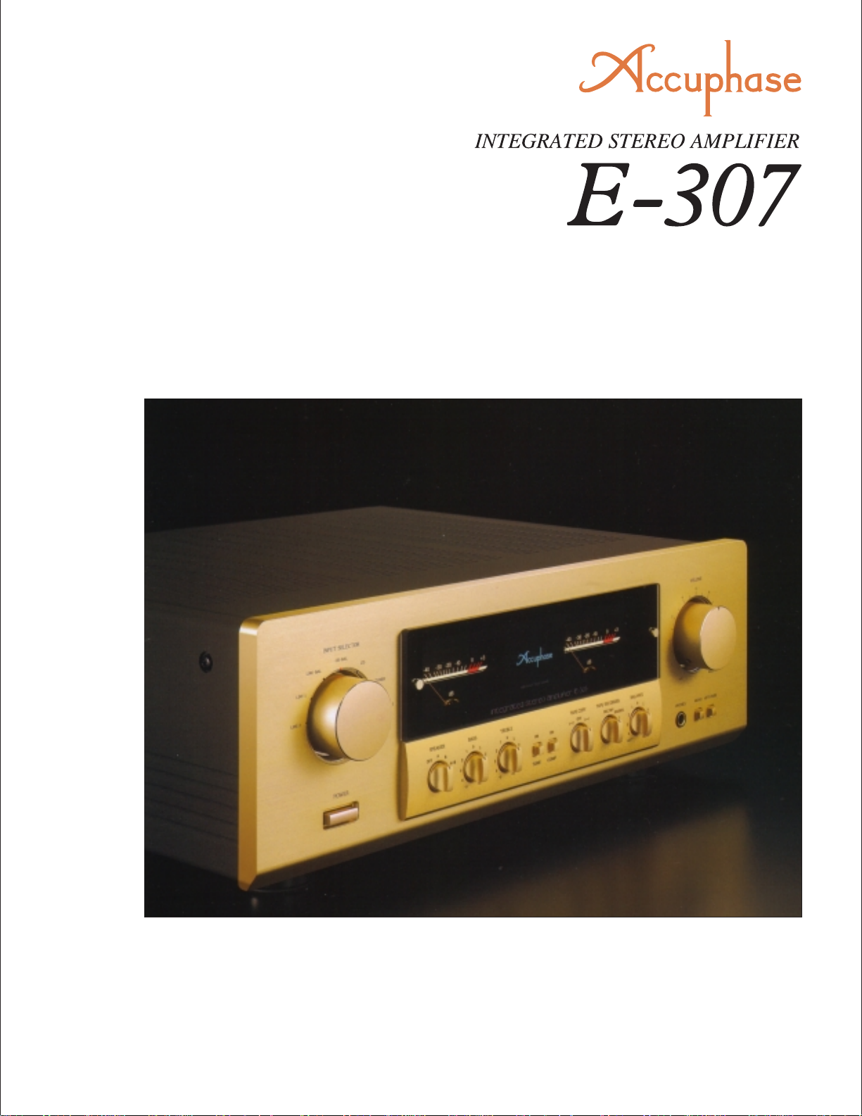
m Parallel push-pull output stage delivers 2 × 100 watts of quality po wer
into 8 ohms m Current feedback topology assures superb phase stability
in the upper frequency range m Logic-controlled relays for shortest signal
paths m Separ ate switch allows independent use of preamplifier and power
amplifier m Large , high-efficiency power transformer m Digital input possible
with option board m Analog record playback possible with option board
Page 2
Witness another rev olution in sound. Integrated amplifier realizes digital input
via option board with high-precision MDS (Multiple Delta Sigma) D/A
conv erter . Current feedback topology assures superb high-range phase fidelity .
Wide-band power transistors in parallel push-pull configuration and large
power transformer deliver 140 watts/channel into 4 ohms and 100 watts/
channel into 8 ohms.
Based on the highly successful Accuphase E-306V
which has become a mainstay in the category of
integrated amplifiers, the E-307 is a further
enhanced and accomplished product for totally
faithful music reproduction. It reflects the extensive
experience Accuphase has gained in building
superb separate-type amplifiers. Ev ery single aspect
has been honed to deliver optimum performance.
An integrated amplifier provides various advantages
such as convenient operation and modest space
requirements. However, because its overall gain is
very high, even the slightest interf erence or crosstalk
at the input can have a considerable effect on the
signal provided at the output. To preclude this
possibility, the E-307 is built with totally separate
preamplifier and power amplifier sections. Both
electrically and structurally, these two parts operate
completely autonomously. Each has its own power
supply and dedicated regulator circuitry. A dedicated
set of inputs and outputs even allows using the
preamplifier and power amplifier as if they were
stand-alone components.
Accuphase's highly acclaimed current feedback
topology is used in both the preamplifier and power
amplifier. This innovative principle eliminates phase
shifts in the upper frequency range and assures
stable operation and uniform frequency response
which does not change with gain. Phase
compensation can be kept at a minimum, and high
amounts of negative feedback with their associated
disadvantages are no longer required, resulting in
excellent transient response, with superb sonic
transparency and detail.
A total of six input positions are provided, including
two balanced inputs for professional-quality noisefree signal transmission. The tape enthusiast will
welcome connectors for two tape recorders, with
easy dubbing in both directions. Tone controls,
loudness compensation, and other convenient
features come in handy. Flexibility is further
enhanced by the option to install a Digital Input
Board with a high-precision MDS (Multiple Delta
Sigma) D/A converter that directly accepts the digital
signal from a CD player or similar, for uncompromiing reproduction quality. An analog disc
input board is also available, allowing high-grade
reproduction of analog records.
Parallel push-pull output stage delivers quality
power: 140 watts/channel into 4 ohms, 100 watts/
channel into 8 ohms
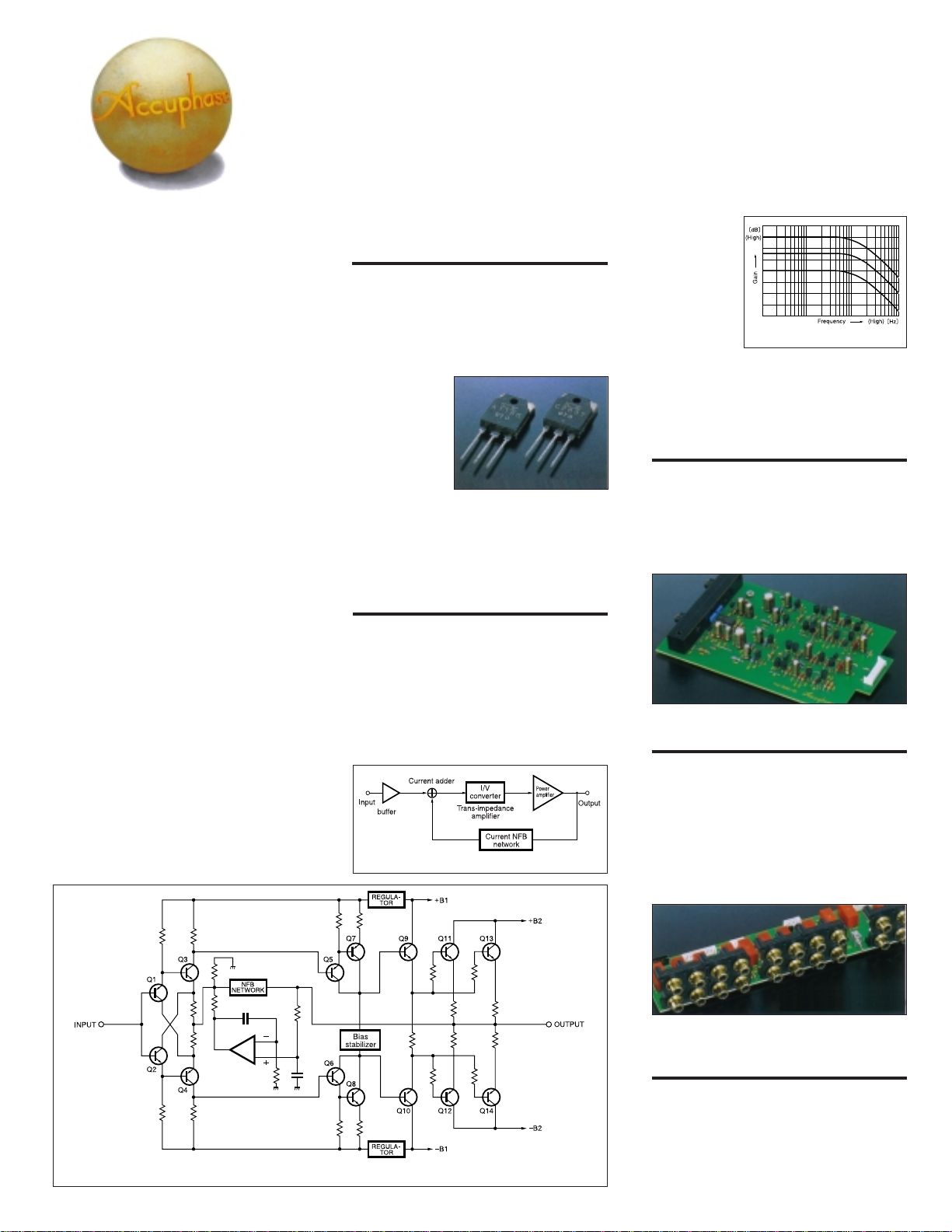
Figure 1 shows a circuit diagram of the power
amplification stage. The power transistors are multiemitter types designed for audio applications. They
have been selected for optimum frequency
response, forward-current transfer ratio linear ity , and
switching performance characteristics. Arranged to
achieve low impedance, the de vices are connected
in parallel and
mounted directly
on a large heat
sink for efficient
dissipation of
thermal energy.
This allows the E307 to deliver
ample power
output, amounting to 140 watts into 4 ohms, 120
watts into 6 ohms, or 100 watts into 8 ohms per
channel.
Current feedback circuit topology in power
amplifier and preamplifier sections prevents
phase shifts
In the E-307, the signal current rather than the more
conventionally used voltage is used for feedback.
Figure 2 shows the operating principle of this circuit.
At the sensing point of the feedback loop, the
impedance is kept low and current detection is
performed. An impedance-con verting amplifier then
converts the current into a voltage to be used as
the feedback signal. Since the impedance at the
current feedback point (current adder in Figure 2) is
very low, there is almost no phase shift. Phase
Figure 2 Principle of current feedback amplifier
High-current power transiters
compensation
can be kept to a
minimum,
resulting in
excellent
transient
response and
superb sonic
transparency.
Figure 3 shows
frequency response for different gain settings of the
current feedback amplifier. The graphs demonstrate
that response remains uniform over a wide range.
Discrete-type line amplifier for superior sonic
purity
To assure optimum performance, the line amplifier
is built entirely from discrete parts. A pure
complementary push-pull circuit is used, and current
feedback topology enhances circuit operation. This
reduces the need for phase compensation, resulting
in effortless, utterly natural and transparent sound.
Highly reliable logic-controlled relays
Program source switching is performed by logiccontrolled relays which are arranged to permit the
shortest possible signal paths. The hermetically
sealed relays are high-quality types developed
specifically for demanding communication
applications. The contacts are twin crossbar types
plated with gold for minimum contact resistance and
outstanding long-term reliability.
Fig. 3 Frequency response with current feedbac k
(response remains uniform also when gain changes)
Figure 1 Circuit diagram of power amplifier section (one channel)
Relays connected directly to
gold-plated input/output jacks
Tone controls use summing active filters for
pure sound
The tone control circuitry in the E-307 was specially
designed with summing active filters such as found
in high-quality graphic equalizers. Figure 4 illustrates
the operation principle of this circuit. The flat signal
is passed straight through, and only when an
adjustment is required, the characteristics are
created at F1 and F2 and added to the signal,
Page 3
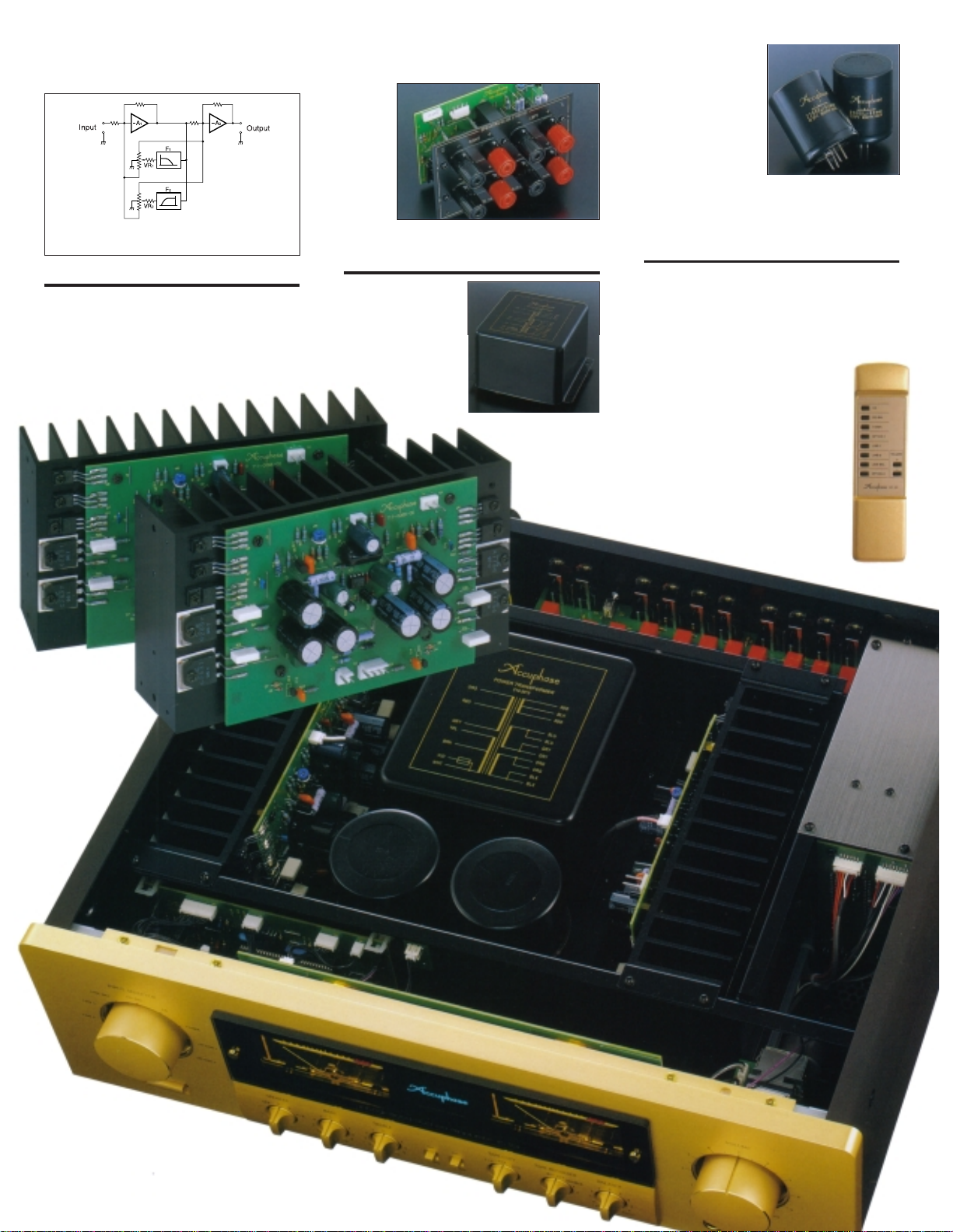
thereby producing the desired change. This design
provides efficient control without diluting signal
purity.
Figure 4 Tone control circuit principle
(Summing active filter type)
Two sets of speaker terminals
The large speaker terminals are made of extruded
high-purity brass material which accept also heavygauge speaker cable. Two sets of outputs with a
speaker selector are provided, and bi-wiring
(supplying the same signal via dual leads to
speakers with separate high-frequency and lowfrequency inputs) is also possible.
Robust power supply with large power
transformer and high filtering capacity
The power supply plays
a vital role as the
source of energy for the
power amplifier section.
The E-307 uses a large
500 VA power
n Power amplifier assembly with parallel push-pull output
devices mounted to large heat sink and current
feedback amplifier circuitry
transformer and two
massive electrolytic
capacitors rated for
22,000 uF each. This
assures ample
reserves also for the
reproduction of
demanding bass
passages. The
preamplifier section
which handles low-level signals has its own
dedicated power supply circuitry to preclude any
possibility of interference via the power supply line.
Large, direct-reading peak power meters
The large analog power meters have a peak hold
function which lets you easily monitor the output
level of the rapidly fluctuating music signal. Thanks
to logarithmic compression, the meters cover a wide
dynamic range.
n Supplied remote commander
RC-20 allows volume adjustment
and input source switching
Page 4
Other Features
n Digital input can be implemented via
option board.
n Analog phono input can be implemented
via option board.
n High-quality v olume control. Supplied
remote commander allows source
switching and volume adjustment.
n Separator switch and dedicated inputs/
outputs enable independent use of
preamplifier and power amplifier sections.
n Versatile input configuration including
balanced connectors.
Balanced input connectors
Option Boards
The rear panel of the E-307 provides two slots in which optional
input boards can be installed easily. Three types of boards are
available for the E-307: Digital Input Board DAC-10, Analog Input
Board AD-10, and Line Input Board LINE-10.
m For reasons of power supply capacity, only one DAC-10 option board
can be installed. Installing two AD-10 boards or a combination of D AC 10 and AD-10 is possible.
m The DAC-10 cannot be used in the models E-407, E-406V, E-306V,
E-211, and C-265.
m The Analog Disc Input Board AD-9 and Line Input Board LINE-9 can
also be used.
The option board shown in the photograph is the DAC-10
Digital Input Board DAC-10
The board features an MDS (Multiple Delta Sigma)
D/A converter and has inputs for coaxial and optical
fiber connections. It assures high-quality reproduction
of digital music signals (sampling frequency range
32 - 96 kHz, 24 bites).
Analog Disc Input Board AD-10
This board contains a high-performance, high-gain
phono equalizer.
Internal DIP switches control MM/MC operation, MC
input impedance, and subsonic filter on/off.
Gain: 36 dB
MM
Input impedance: 47 kilohms
Gain: 62 dB
MC
Inpu t im p e d a n ce : 10/30/100 ohms (selectable)
Line Input Board LINE-10
This option board provides an additional set of
conventional line inputs which can be used to connect
a CD player, tuner, or other component with analog
output.
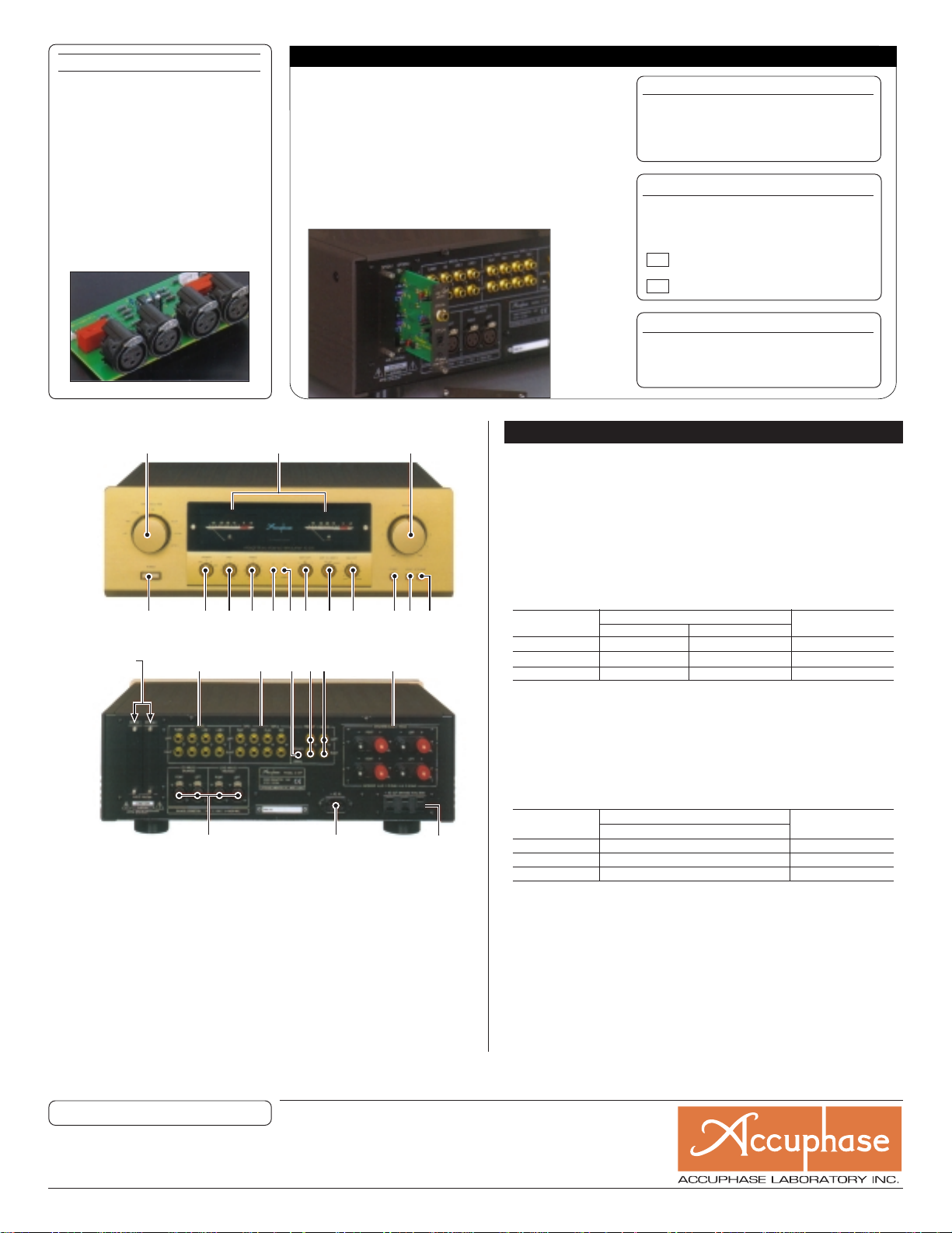
n FRONT PANEL
123
54
6789FG H IJK
n REAR PANEL
Option Board Slots
LMNOP Q
R
1 INPUT SELECTOR
LINE 2 LINE 1 LINE-BAL CD-BAL
CD TUNE OPTION 1 OPTION 2
2 Power Meters (Decibel Scale)
3 VOLUME Control
4 POWER Switch
5 SPEAKER Selector OFF A B A+B
6 BASS Controls
7 TREBLE Controls
8 TONE ON/OFF Button
9 COMP (Loudness Compensator) Switch
F TAPE COPY Selector 1 ➝ 2 OFF 2 ➝ 1
G TAPE RECORDER Selector
REC OFF SOUCE 1 2
★★
S
H BALANCE Control
I PHONES Jack
J MONO Switch
K ATT (Attenuator) Switch
L INPUTS: TUNER, CD, LINE 1, 2
M TAPE 1, 2 PLAY/REC Jacks
N Preamplifier/power amplifier separator swich
O PRE OUT Jacks
P MAIN IN Jacks
Q SPEAKERS T erminals
R CD/LINE INPUTS (BALANCED)
S AC Power Supply Connector
(for supplied power cord)
T SWITCHED Outlets
★
T
★
GUARANTEED SPECIFICATIONS
[Guaranteed specifications are measured according to EIA standard RS-490.]
m Continuous Average Output Power (both channels driven, 20 - 20,000 Hz)
m Total Harmonic Distortion (both channels driven, 20 - 20,000 Hz)
m Intermodulation Distortion 0.01%
m Frequency Response
m Damping Factor 100 (with 8-ohm load, 50 Hz)
m Input Sensitivity, Input Impedance
Input Input impedance
HIGH LEVEL INPUT
BALANCED INPUT
MAIN INPUT 1.13 V 112 mV 20 kΩ
m Output Voltage, Output Impedance PRE OUTPUT: 1.13 V, 50 ohms
m Gain MAIN INPUT ➞ OUTPUT: 28 dB
m T one Controls Turnover frequency and adjustment range
m Loudness Compensation +6 dB (100 Hz) (Volume control setting -30 dB)
m Attenuator -20 dB
m Signal-to-Noise Ratio
Input
HIGH LEVEL INPUT
BALANCED INPUT
MAIN INPUT 122 dB 100 dB
m Power Level Meters Logarithmic compression, peak reading meters dB scale
m Load Impedance 4 - 16 ohms
m Stereo Headphones Suitable impedance: 4 - 100 ohms
m Power Requirements 120 V/230 V (Voltage as indicated on rear panel) AC, 50/60 Hz
m Power Consumption 50 watts idle
m Maximum Dimensions Width 475 mm (18-11/16”)
m Weight 21.6 kg (47.6 lbs) net
For rated output For 1 W output (EIA)
113 mV 11.2 mV 20 kΩ
113 mV 11.2 mV 40 kΩ
140 watts per channel into 4 ohms
120 watts per channel into 6 ohms
100 watts per channel into 8 ohms
0.01%, with 4 to 16 ohms load
HIGH LEVEL INPUT/
20 - 20,000 Hz +0, -0.2 dB (for rated continuous average output)
2 - 150,000 Hz +0, -3.0 dB (for 1 watt output)
Sensitivity
(at rated continuous average output)
HIGH LEVEL INPUT➞ PRE OUTPUT: 20 dB
BASS: 300 Hz ±10 dB (50 Hz)
TREBLE: 3 kHz ±10 dB (20 kHz)
Input shorted, IHF-A weighting
S/N ratio at rated input
104 dB
88 dB 80 dB
240 watts in accordance with IEC-65
Height 170 mm (6-11/16”)
Depth 424 mm (16-11/16”)
26.0 kg (57.3 lbs) in shipping carton
MAIN INPUT
S/N ratio (EIA)
80 dB
Remarks
★
This product is available in versions for 120/230 V AC. Make sure that the v oltage shown on the rear panel matches the AC line voltage in your area.
★
The 230 V AC model does not have the SWITCHED power outlet.
★
The shape of the AC inlet, plug of the supplied power cord, and AC outlet depends on the voltage rating and destination country.
★
These switched AC outlets may not be supplied depending on the safety standards or regulations applicable in the particular country to where the unit is destined.
Supplied accessories: • AC power cord
m Specifications and design subject to change without notice for improvements.
• Remote commander RC-20
http://www.accuphase.com.
PRINTED IN JAPAN L0010 851-0109-00 (AD1)
 Loading...