

Page 1
Using the Setup Wizard
• L2TP Password: Sets a L2TP password for the WAN port. (Default:
L2TP_PASSWORD; Range: 1~32 characters)
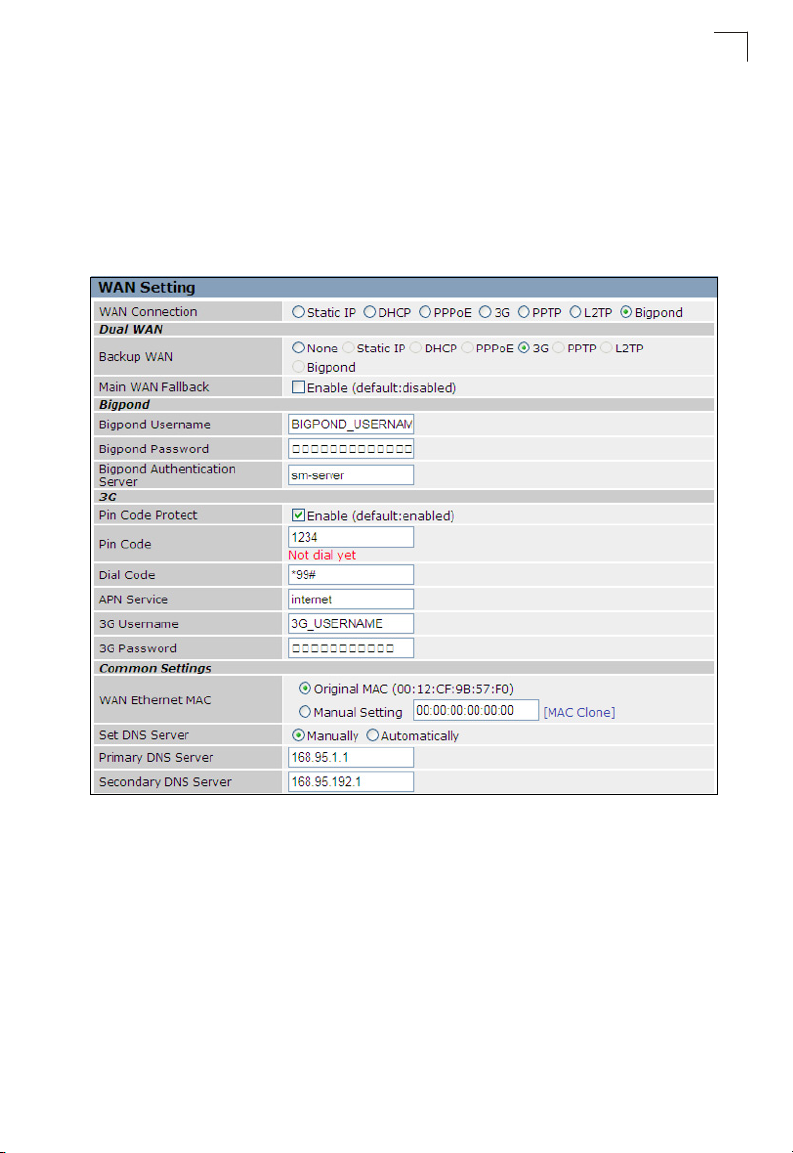
Bigpond
Enables the settings of Telstra Bigpond network service in Australia.
The following example shows the dual WAN function enabled using 3G as a
secondary WAN connection.
4
Figure 4-14. Setup Wizard - WAN Bigpond
• Bigpond Username: Sets the Bigpond user name for the WAN port.
(Default: BIGPOND_USERNAME; Range: 1~32 characters)
• Bigpond Password: Sets a Bigpond password for the WAN port. (Default:
BIGPOND_USERNAME; Range: 1~32 characters)
• Bigpond Authentication Server: Specifies a Bigpond authentication server.
(Default: sm-server)
4-11
Page 2
Initial Configuration
4
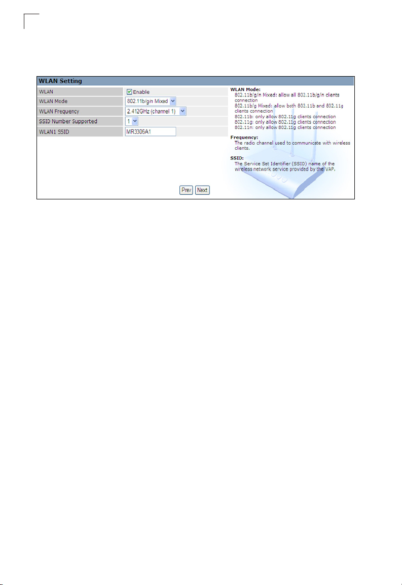
4. WLAN Setting – Enables the wireless interface, selects the operating channel
and configures SSIDs for both VAPs. Click Next after completing the setup.
Figure 4-15. Setup Wizard - WLAN Configuration
The displayed items on this page can be described as follows:
• WLAN – Enables the communication for the VAP wireless interface.
(Default: Enabled)
• WLAN Mode – Defines the radio mode for the VAP interface. See “WLAN Mode”
on page 5-21 for more information. (Default: 802.11b/g/n Mixed)
• WLAN Frequency – The radio channel that the wireless AP/Router uses to
communicate with wireless clients. When multiple access points are deployed in
the same area, set the channel on neighboring access points at least five channels
apart to avoid interference with each other. For example, you can deploy up to
three access points in the same area using channels 1, 6, 11. Note that wireless
clients automatically set the channel to the same as that used by the wireless AP/
Router to which it is linked. Selecting Auto Select enables the wireless AP/Router
to automatically select an unoccupied radio channel. (The supported channels are
dependent on the country code setting.)
Note: To US model owner: To comply with US FCC regulation, the country selection
function has been completely removed from all US models. The above function is
for non- US models only.
• SSID Number Supported – The number of wireless network interfaces (SSIDs)
supported on the device. (Default: 1)
• WLAN1 SSID / WLAN2 SSID – The name of the wireless network service provided
by the VAP. Clients that want to connect to the network must set their SSID to the
same as that of the VAP interface. (Default: “mr3306a1” for WLAN1; “mr3306a2”
for WLAN2; Range: 1-32 characters)
4-12
Page 3
Using the Setup Wizard
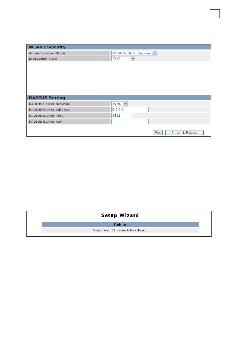
5. WLAN1/WLAN2 Security — Sets the wireless security encryption key for the
wireless network.
Figure 4-16. Setup Wizard - WLAN1 Security
Authentication Mode – Configures the authentication mode used by clients.
See “Authentication Mode” on page 5-28 for more information.
(WLAN1/WLAN2 Defaults: Open)
6. Click Finish & Reboot after completing the configuration changes. Note that all
configuration changes are not saved until the Setup Wizard is completed and
the system has restarted.
When the system restarts, a countdown window displays for 60 seconds.
4
Figure 4-17. Implementing Wizard Settings
4-13
Page 4

4
Initial Configuration
4-14
Page 5
Chapter 5: System Configuration
The wireless AP/Router offers a user-friendly web-based management interface for
the configuration of all the unit’s features. Any PC directly attached to the unit can
access the management interface using a web browser, such as Internet Explorer
(version 6.0 or above).
This chapter describes the wireless AP/Router’s configurable features, all of which
may be accessed through the web interface.
Note: Before accessing the web interface, first set the device to Router or AP Mode
using the switch on the bottom panel. Note that the unit reboots when the
operating mode is changed.
It is recommended to make initial configuration changes by connecting a PC directly
to one of the wireless AP/Router's LAN ports. The wireless AP/Router has a default
IP address of 192.168.2.1 and a subnet mask of 255.255.255.0. If your PC is set to
"Obtain an IP address automatically" (that is, set as a DHCP client), you can connect
immediately to the web interface. Otherwise, you must set your PC IP address to be
on the same subnet as the wireless AP/Router (that is, the PC and wireless AP/
Router addresses must both start 192.168.2.x).
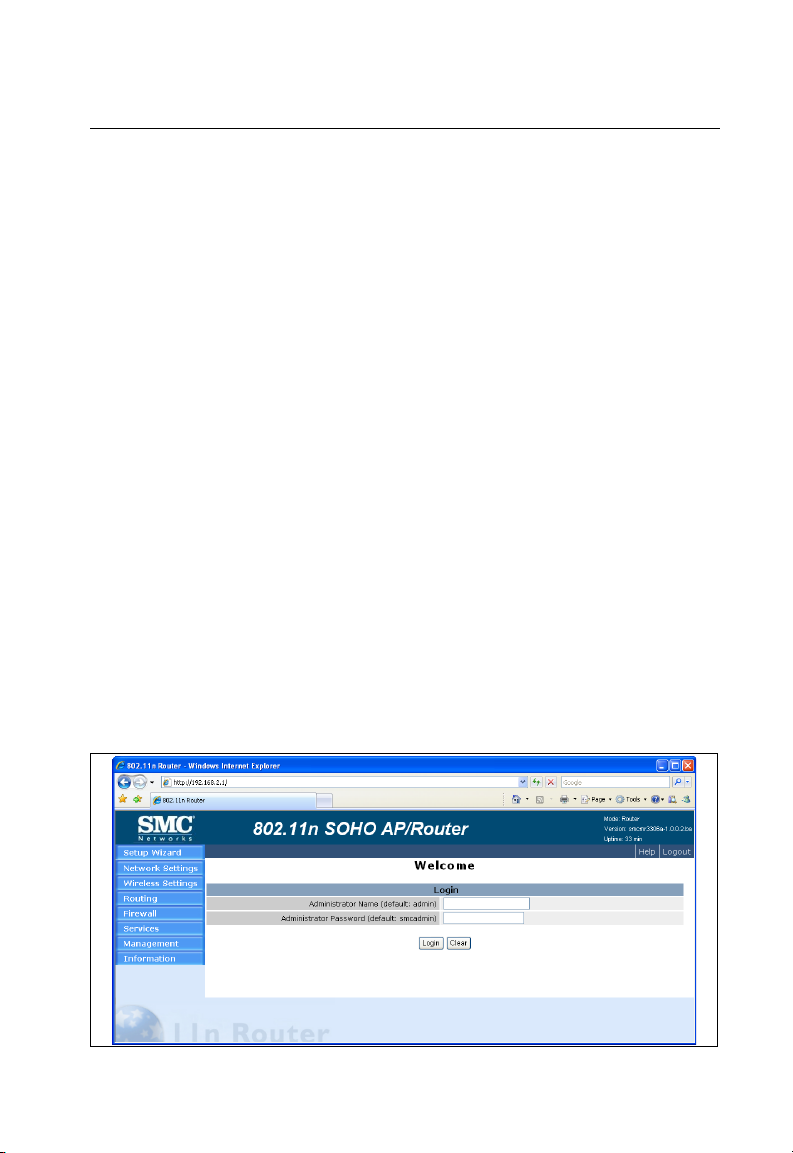
To access the configuration menu, follow these steps:
1. Use your web browser to connect to the management interface using the
default IP address of 192.168.2.1.
2. Log into the wireless AP/Router management interface by entering the default
username “admin” and password also “smcadmin,” then click Login.
Note: It is strongly recommended to change the default user name and password the
first time you access the web interface. For information on changing user names
and passwords, See “Admin Accounts and Remote Administration” on page 5-60
Figure 5-1. Login Page
5-1
Page 6
System Configuration
5
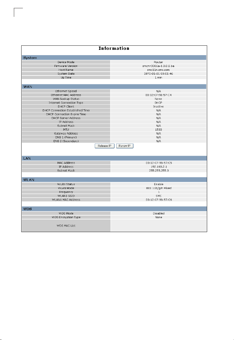
The System Information page displays the System, Management IP, WAN, LAN,
WLAN, and WDS settings.
5-2
Figure 5-2. Home Page (Router mode)
Page 7

The information in this chapter is organized to reflect the structure of the web
management screens for easy reference.
The Configuration pages include the options in the table below. For details on
configuration for each feature, see the corresponding page number.
Note: The displayed pages and settings may differ depending on whether the unit is in
Router or AP Mode.
Table 5-1. Configuration Options
Menu Description Mode Page
Network Settings 5-4
Management IP Specifies an IP and subnet mask for management access AP 5-4
WAN Configures settings for the wide area network Router 5-5
LAN Sets the unit’s IP address and enables DNS Router 5-18
QoS Configures Quality of Service (QoS) for wireless traffic Router 5-19
Wireless Settings 5-21
Basic Setting Configures wireless transmission method, frequency and SSID Both 5-22
Advanced Setting Configures advanced wireless transmission values Both 5-24
WLAN Security Configures radio security parameters for the VAP interface Both 5-26
WLAN MAC ACL Configures MAC ACLs for the VAP interface Both 5-36
WPS Configures WPS settings Both 5-38
Routing 5-41
Static Route Configures IP settings for routing of traffic through the AP/
Dynamic Route Enables RIP protocols for the LAN and WAN ports. Router 5-42
Multicast Routing Enables multicast routing. Router 5-43
Firewall 5-44
NAT Configures NAT settings Router 5-44
Packet Filter Configures WAN, LAN and MAC packet filtering Router 5-48
URL Filter Configures web site address filtering Router 5-50
Security Enables intrusion detection Router 5-51
Services 5-52
DHCP Configures the DHCP server settings Router 5-52
UPnP Enables UPnP Router 5-53
DDNS Configures Dynamic DNS settings Router 5-54
System Log Setting Enables system logs Both 5-55
Date/Time Configures NTP settings Both 5-57
Router from another subnet
Router 5-41
5
5-3
Page 8
System Configuration
5
Table 5-1. Configuration Options
Menu Description Mode Page
PING Test Performs a loopback test on a specified IP address Both 5-59
Management 5-60
Admin Enables remote administration and configures user accounts
for control of the unit
Config Backups and restores the configuration data and restores the
factory defaults
Firmware Upgrades system software from a local file and enables
provisioning updates
Information 5-64
System Information Displays the current system status Both 5-64
Routing Table Displays information on configured routes Router 5-67
Packet Statistics Displays received and sent packet statistics Both 5-67
System Log Displays the system message log Both 5-69
Both 5-60
Both 5-62
Both 5-63
Network Settings
The Network Settings pages allow you to manage basic system configuration
settings.
Note: In AP mode, the wireless AP/Router’s Network Settings options are significantly
reduced.
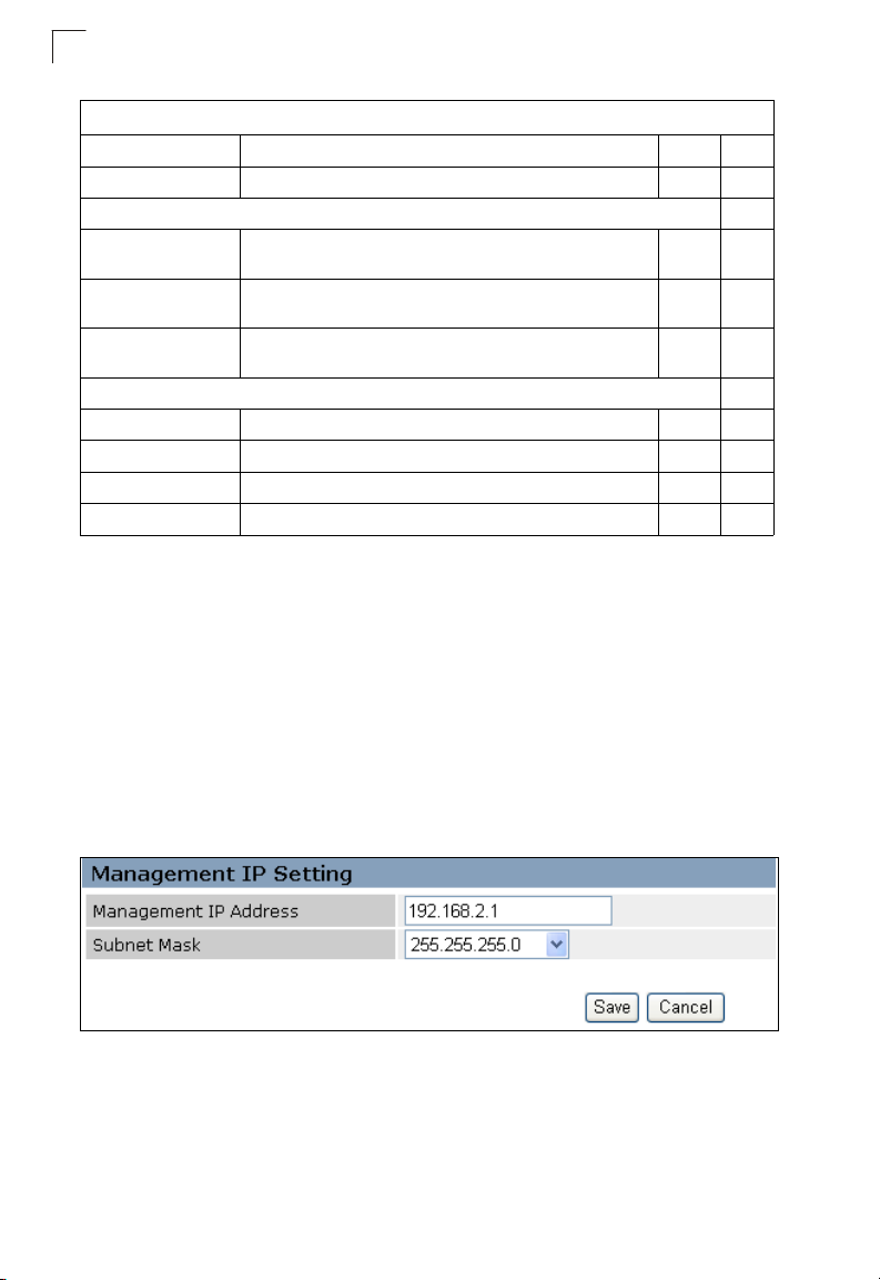
Management IP
Assigns an IP address for connecting to the wireless AP/Router. Click on "Network
Settings" followed by "Management IP.”
Figure 5-3. IP Settings (AP mode)
• Management IP Address – Specifies an IP address for management of the
wireless AP/Router. Valid IP addresses consist of four decimal numbers, 0 to 255,
separated by periods. (Default: 192.168.1.254.)
5-4
Page 9
WAN Setting
• Subnet Mask – Indicates the local subnet mask. Select the desired mask from the
drop down menu. (Default: 255.255.255.0)
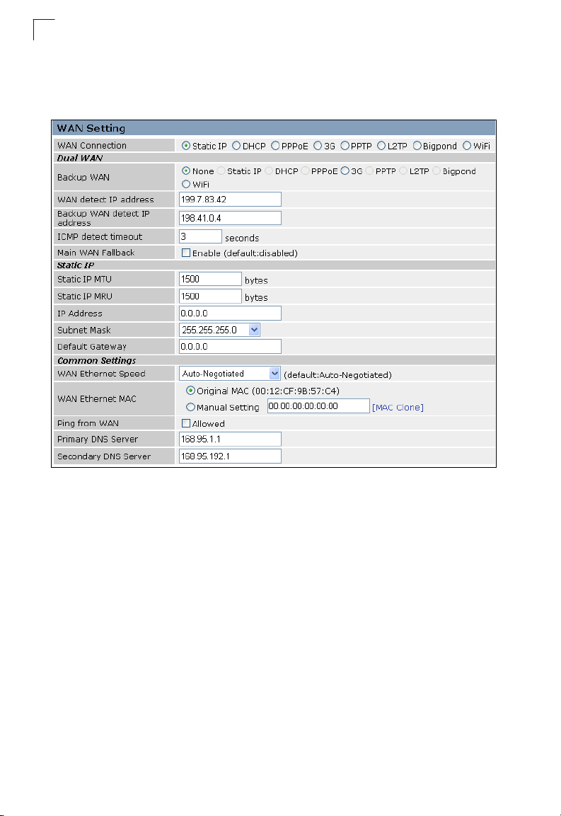
WAN Setting
Specifies the Internet connection parameters. Click on “Network Settings” followed
by “WAN.”
WAN Connection
By default, the access point WAN port is configured with DHCP enabled. After you
have network access to the access point, you can use the web browser interface to
modify the initial IP configuration, if needed. The options are Static IP, DHCP,
PPPoE, 3G, PPTP, L2TP and Bigpond. Each option changes the parameters below
it. (Default: DHCP)
Backup WAN
A backup failsafe connection for the WAN port (Dual WAN.) Options are determined
by the WAN Connection selected. Backup WAN and WAN Connection parameters
are identical for each of their seven equivilent modes: Static IP, DHCP, PPPoE, 3G,
PPTP, L2TP and Bigpond. (Default: None)
• Main WAN Fallback: When the Backup WAN is enabled, Main WAN Fallback can
be enabled to periodically search the primary WAN port for recovery of the lost
connection. If connection is re-established the connection switches back to the
primary WAN connection. (Default: Disabled)
Note: When 3G is selected as the primary WAN Connection the Backup WAN may not
be 3G also.
5
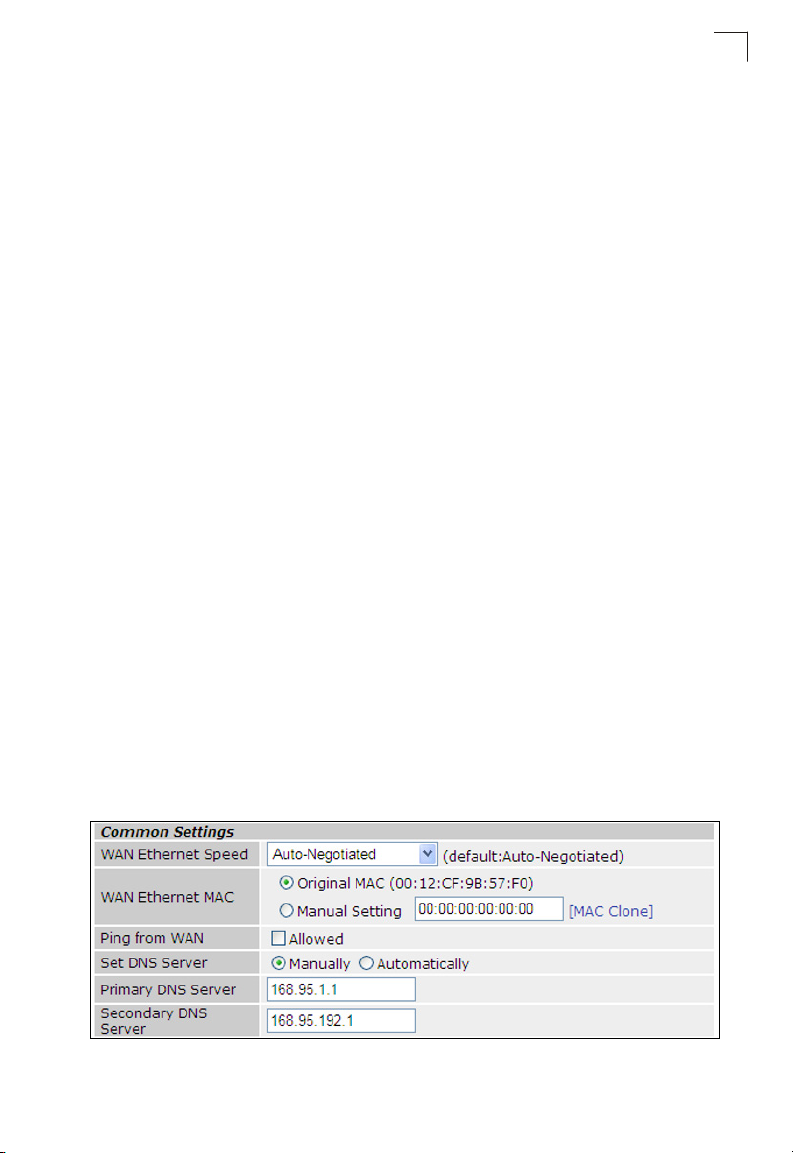
Common Settings
Common Settings are the same for each Static IP, DHCP, PPPoE, 3G, PPTP, L2TP,
Bigpond and Wi-Fi modes. The following section describes their parameters.
Figure 5-4. WAN Common Settings (Router Mode)
5-5
Page 10

System Configuration
5
WAN Ethernet Speed — Configures the WAN Ethernet connection speed.
(Default: Auto-Negotiated)
• Auto-Negotiated – Enables auto-negotiation.
• 100Mbps, Full-Duplex – Forces 100 Mbps full-duplex operation.
• 100Mbps, Half-Duplex – Forces 100 Mbps half-duplex operation.
• 10Mbps, Full-Duplex – Forces 10 Mbps full-duplex operation.
• 10Mbps, Half-Duplex – Forces 10 Mbps half-duplex operation.
WAN Ethernet MAC — Some ISPs limit Internet connections to a specified MAC
address of one PC. This setting allows you to manually change the MAC address of
the wireless AP/Router's WAN interface to match the PC's MAC address provided to
your ISP for registration. You can enter the registered MAC address manually by
typing it in the boxes provided. Otherwise, connect only the PC with the registered
MAC address to the wireless AP/Router, then click the “MAC Clone.” (Default:
Original MAC)
Note: If you are unsure of the PC MAC address originally registered by your ISP, call
your ISP and request to register a new MAC address for your account. Register
the default MAC address of the wireless AP/Router.
• Original MAC – Specifies a preset MAC address to uniquely identify the unit.
• Manual Setting – Configures a specific MAC address to use for the WAN
connection.
• Ping from WAN – Sends a ping from the wireless AP/Router to the WAN
connection to test for connectivity.
• Set DNS Server – Allows manual or automatic selection of DNS severs.
• Primary DNS Server: The IP address of the Primary Domain Name Server on the
network. A DNS maps numerical IP addresses to domain names and can be used
to identify network hosts by familiar names instead of the IP addresses. If you have
one or more DNS servers located on the local network, type the IP addresses in
the text fields provided. Otherwise, leave the addresses as all zeros (0.0.0.0).
• Secondary DNS Server: The IP address of the Secondary Domain Name Server
on the network.
5-6
Page 11

WAN Setting
DHCP
DHCP (dynamic host control protocol) is set as default for the primary WAN
connection. To enable DHCP for the Backup WAN you must select 3G as the
primary WAN connection.
Figure 5-5. WAN Settings for DHCP (Router mode)
5
DHCP — Enables DHCP for the WAN port.
• DHCP MTU: Sets the maximum packet size that the WAN port may transmit. The
Maximum Transmission Unit (MTU) is expressed in bytes. (Default:1500 bytes)
• DHCP MRU: Sets the maximum packet size that the unit may receive from other
units on the network and sends a message to inform them of the set threshold.
Maximum Receive Unit (MRU) is expressed in bytes. (Default: 1500 bytes)
5-7
Page 12
System Configuration
5
Static IP
Configures the unit to use the same IP address each time it connects.
Figure 5-6. WAN Settings for Static IP (Router mode)
Static IP — Configures a static IP for the WAN port.
• Static IP MTU: Sets the maximum packet size that the WAN port may transmit.
The Maximum Transmission Unit (MTU) is expressed in bytes. (Default:1500
bytes)
• Static IP MRU: Sets the maximum packet size that the unit may receive from other
units on the network and sends a message to inform them of the set threshold.
Maximum Receive Unit (MRU) is expressed in bytes. (Default: 1500 bytes)
• IP Address: Sets the static IP address as given by the PPTP service provider.
(Default: 0.0.0.0, available when PPTP Network Mode is set to static IP.)
• Subnet Mask: Sets the static IP subnet mask. (Default: 255.255.255.0, available
when PPTP Network Mode is set to static IP.)
• Default Gateway: The IP address of the gateway router for the wireless AP/
Router, which is used if the requested destination address is not on the local
subnet.
5-8
Page 13
WAN Setting
• WAN IP Alias – Adds more than one IP address to the network interface for
multiple connectivity.
- Enable: Enables the specified IP address.
- Add: Specifies a WAN IP alias.
- Change: Changes the already specified IP alias.
- Delete: Deletes the IP alias.
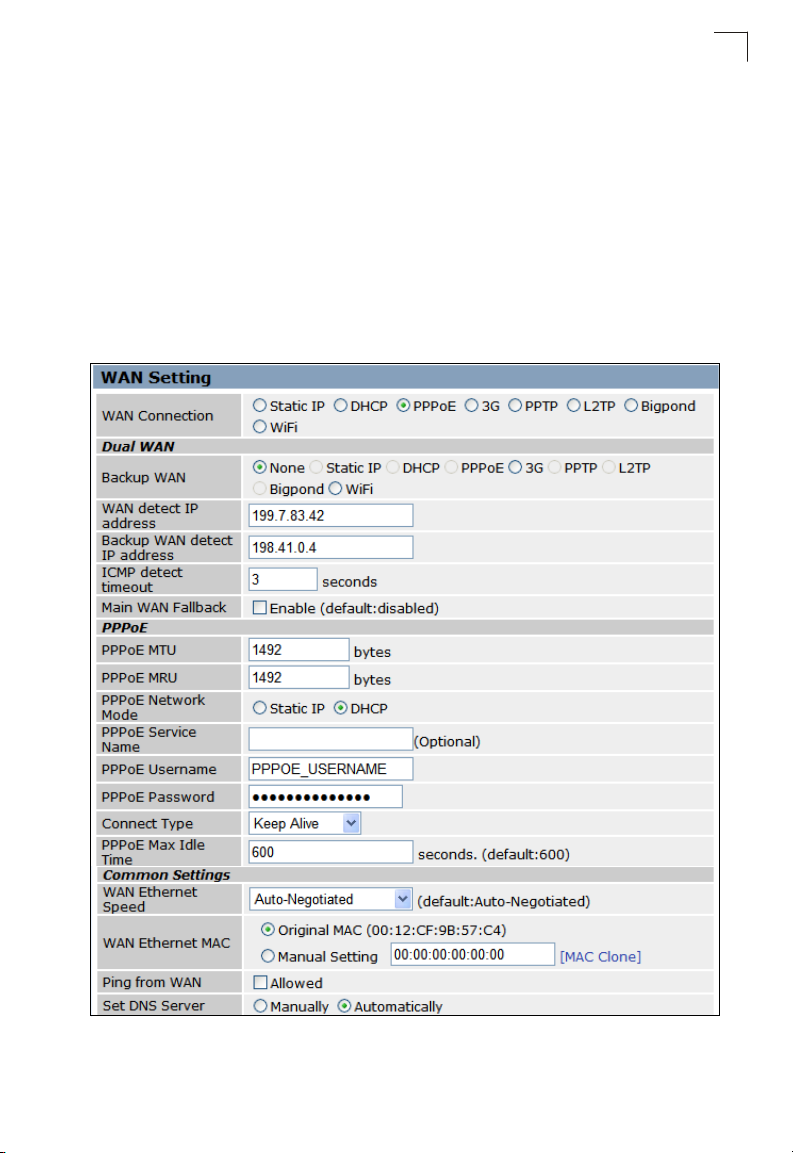
PPPoE
Enable the wireless AP/Router IP address to be assigned automatically from an
Internet service provider (ISP) through an ADSL modem using Point-to-Point
Protocol over Ethernet (PPPoE).
5
Figure 5-7. WAN Settings for PPPoE (Router mode)
5-9
Page 14

System Configuration
5
PPPoE — Configures PPPoE.
• PPPoE MTU: Sets the maximum packet size that the WAN port may transmit. The
Maximum Transmission Unit (MTU) is expressed in bytes. (Default:1492 bytes)
• PPPoE MRU: Sets the maximum packet size that the unit may receive from other
units on the network and sends a message to inform them of the set threshold.
Maximum Receive Unit (MRU) is expressed in bytes. (Default: 1492 bytes)
Note: Only change the default MTU and MRU values if specifically instructed by the
PPPoE service provider.
• PPPoE Network Mode: Sets the PPPoE network mode to Static IP or DHCP.
(Default: DHCP)
• IP Address: Sets the static IP address as given by the PPPoE service provider.
(Default: 0.0.0.0, available when PPPoE Network Mode is set to static IP.)
• PPPoE Service Name (Optional): The service name assigned for the PPPoE
connection. The service name is normally optional, but may be required by some
service providers. (Range: 1-32 alphanumeric characters)
• PPPoE User Name: Sets the PPPoE username for the WAN port.
(Default: PPPOE_USERNAME; Range: 1~32 characters)
• PPPoE Password: Sets a PPPoE password for the WAN port.
(Default: PPPOE_PASSWORD; Range: 1~32 characters)
• Connect Type: Selects the connection type as Keep Alive or Auto Connect.
(Default: Keep Alive)
• PPPoE Max Idle Time: The maximum length of inactive time the unit will stay
connected to the DSL service provider before disconnecting. This feature only
works when Connect Type is set to "Auto-Connect." (Default: 600 seconds)
5-10
Page 15
WAN Setting
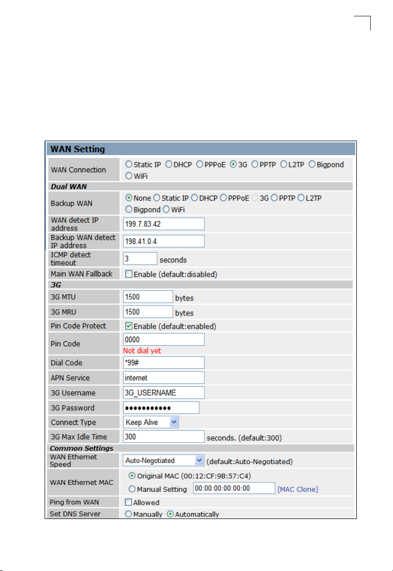
3G
3G technologies enable cellular network operators to offer users a wider range of
more advanced services while achieving greater network capacity through improved
spectral efficiency. Services include wide-area wireless voice telephony, video calls,
and broadband wireless data, all in a mobile environment.
To use the 3G option, you need to first connect a 3G/3.5G USB modem to the USB
port on the back of the unit and have registered an account with a cellular operator.
5
Figure 5-8. WAN Settings for 3G (Router mode)
5-11
Page 16

System Configuration
5
3G — Enables a 3G/3.5G wide-area wireless cellular link on the USB port using an
optional USB modem.
• Pin Code Protect: Enables the use of a PIN code (personal identification number)
to encrypt access to the wireless 3G connection. Some service providers do not
require PIN code authentication. If the PIN code for your 3G/3.5G modem is
disabled, then disable this function. (Default: Enabled)
•Pin Code: Specifies a PIN code number that corresponds with that set on your 3G/
3.5G USB modem.
•Dial Code: A dialled access code that connects the USB device to the service
provider.
• APN Service: The name that uniquely identifies the cellular operator, access point
name (APN).
•3G Username: The username of the account registered with the service provider.
• 3G Password: The password of the account registered with the service provider.
5-12
Page 17
WAN Setting
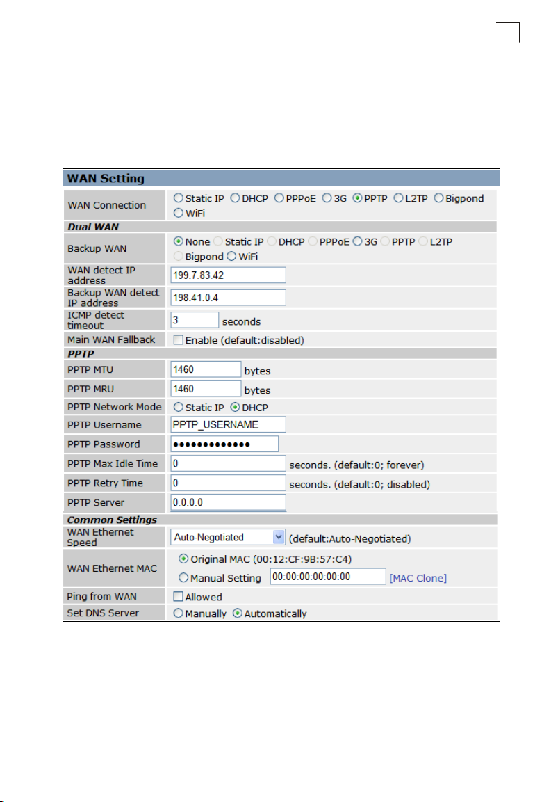
PPTP
Enable the Point-to-Point Tunneling Protocol (PPTP) for implementing virtual private
networks. The service is provided across the Internet in many European countries.
The following example shows PPTP selected as the primary WAN connection with
3G enabled as a backup WAN.
5
Figure 5-9. WAN Settings for PPTP (Router mode)
PPTP — Enable the Point-to-Point Tunneling Protocol (PPTP) for implementing
virtual private networks. The service is provided across the Internet in many
European countries.
• PPTP MTU: Sets the maximum packet size that the WAN port may transmit. The
Maximum Transmission Unit (MTU) is expressed in bytes. (Default:1460 bytes)
5-13
Page 18
System Configuration
5
• PPTP MRU: Sets the maximum packet size that the unit may receive from other
units on the network and sends a message to inform them of the set threshold.
Maximum Receive Unit (MRU) is expressed in bytes. (Default: 1460 bytes)
Note: Only change the default MTU and MRU values if specifically instructed by the
PPTP service provider.
• PPTP Network Mode: Sets the PPTP network mode to Static IP or DHCP.
(Default: DHCP)
• PPTP Username: Sets the PPTP user name for the WAN port.
(Default: PPTP_USERNAME; Range: 1~32 characters)
• PPTP Password: Sets a PPTP password for the WAN port. (Default:
PPTP_PASSWORD; Range: 1~32 characters)
• PPTP Server: Configures the IP address of the PPTP server interface. (Default:
0.0.0.0)
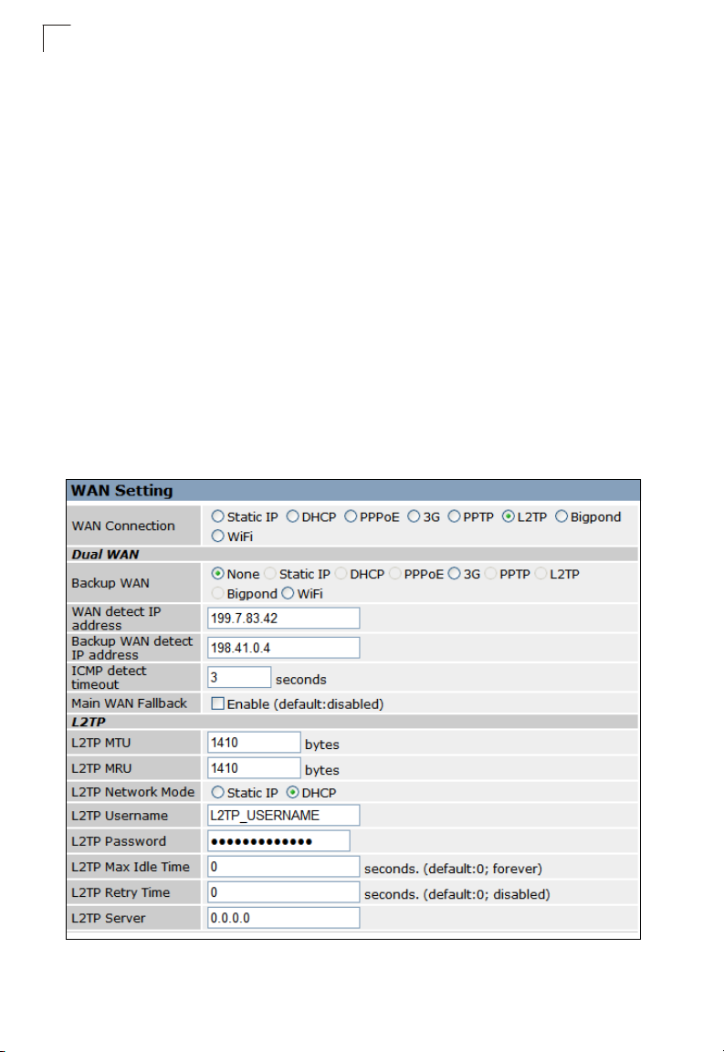
L2TP
Enable the Layer Two Tunneling Protocol (L2TP) for implementing virtual private
networks. The service is provided across the Internet in many European countries.
5-14
Figure 5-10. WAN Settings for L2TP (Router mode)
Page 19

WAN Setting
L2TP — Enable the Layer Two Tunneling Protocol (L2TP).
• L2TP MTU: Sets the maximum packet size that the WAN port may transmit. The
Maximum Transmission Unit (MTU) is expressed in bytes. (Default:1410 bytes)
• L2TP MRU: Sets the maximum packet size that the unit may receive from other
units on the network and sends a message to inform them of the set threshold.
Maximum Receive Unit (MRU) is expressed in bytes. (Default: 1410 bytes)
• Only change the default MTU and MRU values if specifically instructed by the
PPTP service provider.
• L2TP Network Mode: Sets the L2TP IP address assignment to Static IP or DHCP.
(Default: DHCP)
• IP Address: Sets the static IP address as given by the L2TP service provider.
(Default: 0.0.0.0, available when L2TP Network Mode is set to static IP.)
• Subnet Mask: Sets the static IP subnet mask. (Default: 255.255.255.0, available
when L2TP Network Mode is set to static IP.)
• Default Gateway: The IP address of the gateway router for the wireless AP/
Router, which is used if the requested destination address is not on the local
subnet.
• L2TP Username: Sets the L2TP user name for the WAN port.
(Default: L2TP_USERNAME; Range: 1~32 characters)
• L2TP Password: Sets a L2TP password for the WAN port. (Default:
L2TP_PASSWORD; Range: 1~32 characters)
• L2TP Max Idle Time: The maximum length of inactive time the unit will stay
connected to the DSL service provider before disconnecting. (Default: 15 seconds;
Range: 5 ~ 600 seconds)
• L2TP Retry Time After Disconnect: Sets a L2TP retry time after the network is
disconnected. (Default: 0 seconds; disabled)
• L2TP Server: Configures the IP address of the L2TP server interface. (Default:
0.0.0.0)
5
5-15
Page 20
System Configuration
5
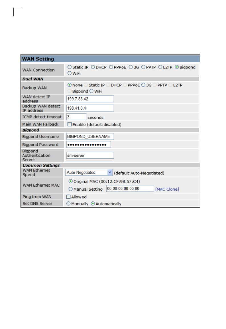
Bigpond
BigPond is an Australian Internet service provider, is a subsidiary of Telstra and
owns a majority share of internet penetration in Australia.
Figure 5-11. WAN Settings for Bigpond (Router mode)
Bigpond — Enables the settings of Telstra Bigpond network service in Australia.
• Bigpond Username: Sets the Bigpond user name for the WAN port.
(Default: BIGPOND_USERNAME; Range: 1~32 characters)
• Bigpond Password: Sets a Bigpond password for the WAN port. (Default:
BIGPOND_USERNAME; Range: 1~32 characters)
• Bigpond Authentication Server: Specifies a Bigpond authentication server.
(Default: sm-server)
5-16
Page 21
WAN Setting
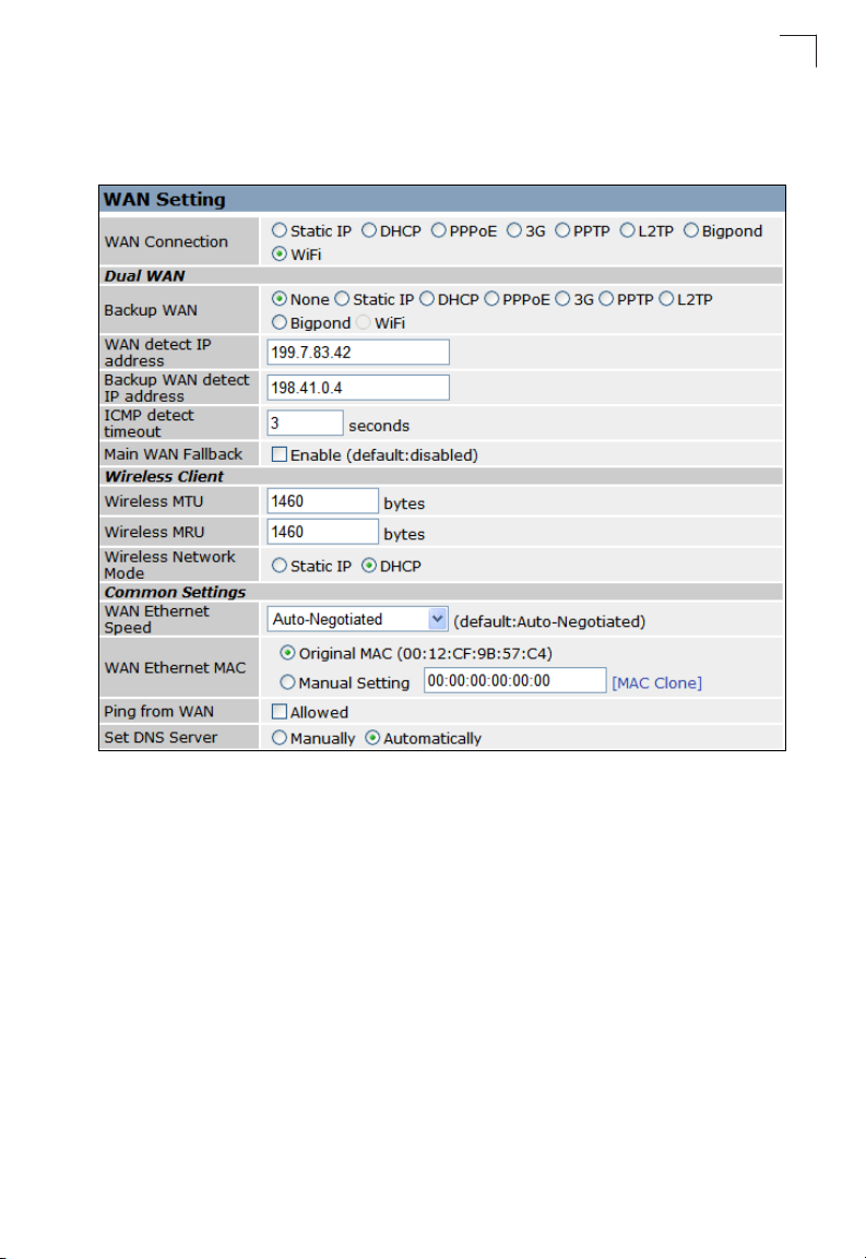
Wi-Fi
Wi-Fi enables a WAN connection over a wireless 802.11a/b/g/n connection.
5
Figure 5-12. WAN Settings for Wi-Fi (Router mode)
Wireless Client — Enables one of the units VAPs to act as a wireless connection to
the WAN port.
• Wireless MTU: Sets the maximum transmission units in bytes.
(Default: 1460 bytes)
• Wireless MRU: Sets the maximum receive units in bytes. (Default: 1460 bytes)
• Wireless Network Mode: Sets the wireless network mode. (Default: DHCP)
- Static IP: Select this option for a static manually configured IP address.
- DHCP: Select this option to enable the client to obtain its IP address from a
DHCP server.
5-17
Page 22
System Configuration
5
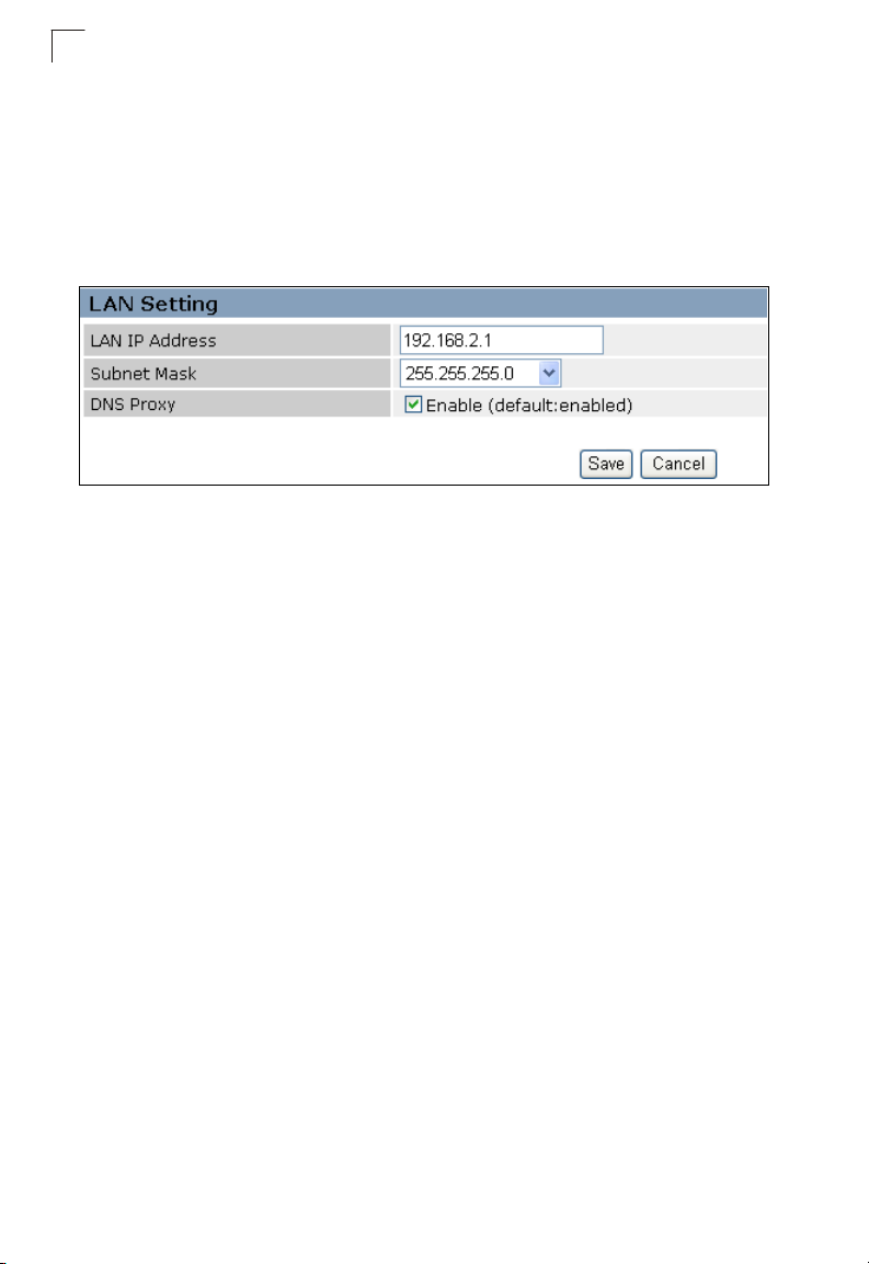
LAN Setting
The wireless AP/Router must have a valid IP address for management using a web
browser and to support other features. The unit has a default IP address of
192.168.1.254. You can use this IP address or assign another address that is
compatible with your existing local network. Click on "Network Settings" followed by
"LAN."
Figure 5-13. LAN Settings (Router mode)
• LAN IP Address – Valid IP addresses consist of four decimal numbers, 0 to 255,
separated by periods. The default setting is 192.168.1.254.
• Subnet Mask – Indicate the local subnet mask. (Default: 255.255.255.0. )
• DNS Proxy – Enables DNS proxy on the LAN port. (Default: Enabled)
5-18
Page 23
LAN Setting
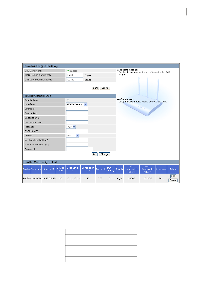
QoS Setting
The QoS setting page is used to configure Quality of Service (QoS) for Traffic
Prioritization and Bandwidth Management. Quality of Service (QoS) provides users
the control over which type of outgoing data traffic is given priority by the router. The
throughput rate of both the upload and download data passed through the wireless
AP/Router can be throttled.
5
Figure 5-14. QoS Settings (Router mode)
Bandwidth QoS Setting — The maximum upload and download speeds of the
Internet connection on the WAN port. It is recommended that you set these values at
between 85-90% of your true speeds. Most broadband services are rated in
Megabits per second (Mbps). To convert Mbps to Kilobits per second (Kbps),
multiply the value by 1024. The following table lists the most common broadband
service speeds:
Mbps Kilobits
1 1024
2 2048
3 3072
4 4069
6 6144
5-19
Page 24

System Configuration
5
Mbps Kilobits
8 8192
12 12288
• QoS Bandwidth – Enables the QoS bandwidth management and traffic control.
• WAN Upload Bandwidth – Sets the maximum WAN upload bandwidth. (Default:
102400 kbps)
• LAN Download Bandwidth – Sets the maximum LAN download bandwidth.
(Default: 102400 kbps)
Traff ic C ont rol QoS — The feature is applied when the applications use static ports
to provide services. The wireless AP/Router can map traffic using specific TCP/UDP
ports to one of the QoS priorities; low, medium, high, and highest. (Maximum 32
entries are allowed.)
•Enable – Activates an application port-based QoS entry. (Default: Disabled)
•Interface – Specifies the LAN ports (download) or WAN port (upload).
• Source IP – The source IP address.
• Source Port – Specifies source TCP/UDP port numbers used by an application.
Multiple ports can be specified, for example, you can enter "1000-2000" for a
continuous port range. Also, specific ports or port ranges can be entered together
in one expression, for example "1000,2000-2100,3000." Up to eight elements can
be supported in each expression. (Range: 1-65535)
• Destination IP – The destination IP address.
• Desination Port – Specifies destination TCP/UDP port numbers used by an
application. Multiple ports can be specified, for example, you can enter
"1000-2000" for a continuous port range. Also, specific ports or port ranges can be
entered together in one expression, for example "1000,2000-2100,3000." Up to
eight elements can be supported in each expression. (Range: 1-65535)
•Protocol – Specifies TCP or UDP.
•DSCP – Differentiated Services Code Point (DSCP) specifies a field in the header
of IP packets for packet classification purposes.
•Priority – Selects Low, Medium, High or Highest as the QoS priority specified for
an application.
• Minimum Bandwidth – Specifies the smallest bandwidth allowed.
• Maximum Bandwidth – Specifies the largest bandwidth allowed.
• Comment – An optional field to make notation.
• Action – Specifies an action to take on the QoS table entry.
- Change: By selecting an entry from the table, its parameters display in an
editable form. Click "Change" to save parameters once you have updated them.
- Add: Adds a newly configured QoS entry to the table.
- Edit: Click "Edit" to highlight a configured QoS entry to modify its parameters.
- Delete: Deletes QoS entry from the table.
5-20
Page 25
Wireless Settings
Wireless Settings
The IEEE 802.11n interfaces include configuration options for radio signal
characteristics and wireless security features.
The wireless AP/Router can operate in five modes, mixed 802.11b/g/n, mixed
802.11b/g, 802.11b only, 802.11g only or 802.11n only. Also note that 802.11g is
backward compatible with 802.11b, and 802.11n is backward compatible with both
802.11b/g at slower data transmit rates.
Each radio supports two virtual access point (VAP) interfaces, referred to as WLAN1
and WLAN2. Each VAP functions as a separate access point, and can be configured
with its own Service Set Identification (SSID) and security settings. However, most
radio signal parameters apply to both VAP interfaces. The configuration options are
nearly identical, and are therefore both covered in this section of the manual.
Traffic to specific VAPs can be segregated based on user groups or application
traffic. Both VAPs can have up to 64 wireless clients, whereby the clients associate
with these VAPs the same as they would with a physical access point.
Note: The radio channel settings for the access point are limited by local regulations,
which determine the number of channels that are available. See “Specifications”
on page B-1“ for additional information on the maximum number channels
available.
The hardware switch feature to toggle between Router and AP Mode, located on the
base of the wireless AP/Router, affects some of the Wireless Interface parameters.
However, most radio signal parameters apply in both modes so will be described
together in the following sections.
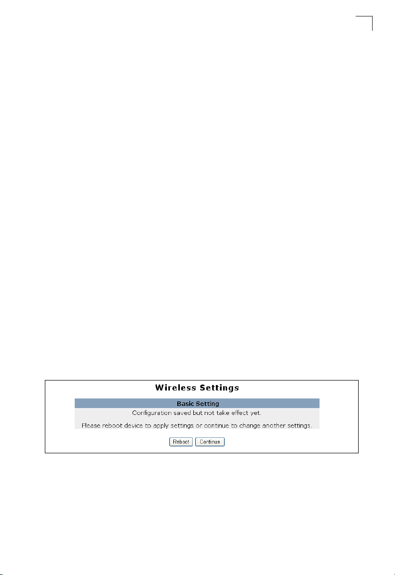
Changing settings in the Wireless Settings configuration and clicking “submit"
prompts you to either “Reboot” for your changes to immediately take effect, or
“Continue” to continue making configuration changes without them taking effect until
you next reboot.
5
Figure 5-15. Changing Settings
5-21
Page 26
System Configuration
5
Choosing to reboot after making configuration changes triggers a countdown
window that requires 60 seconds to complete.
Figure 5-16. Implementing Changed Settings
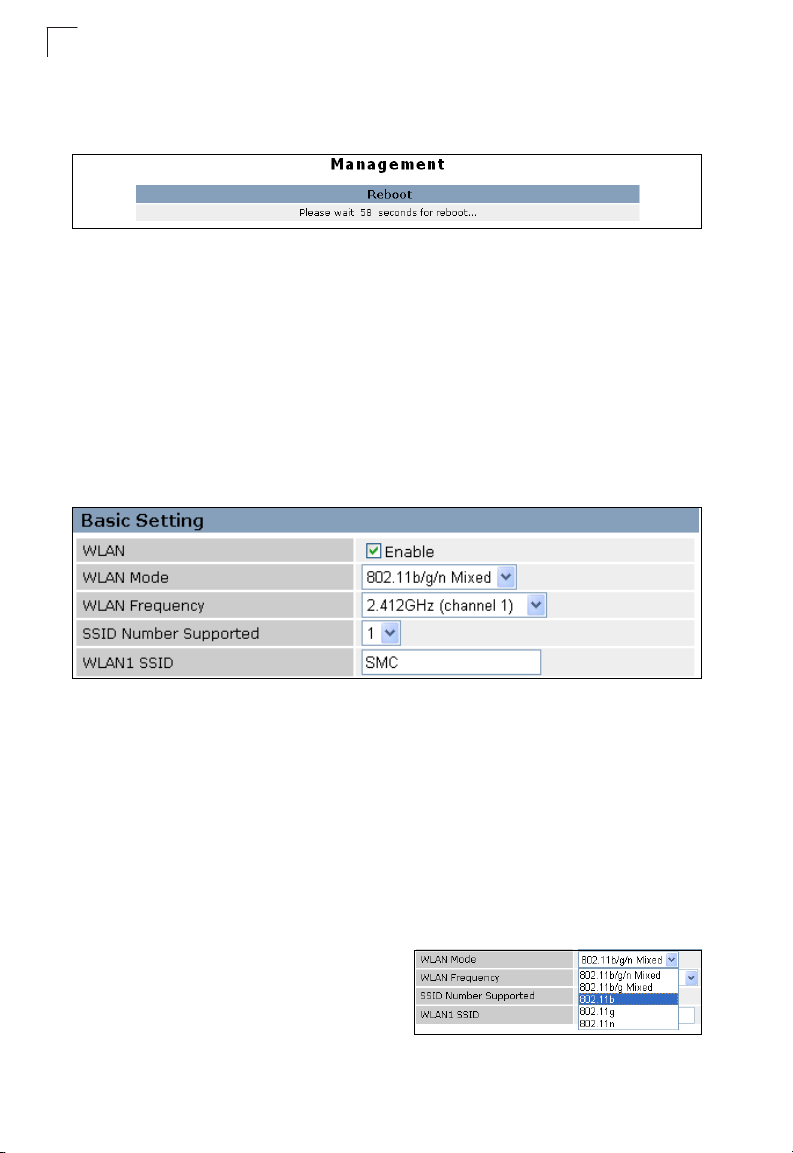
Basic Settings
The Basic Setting page allows you to enable the wireless interface, select which
radio mode to use, choose the transmit frequency and configure SSIDs.
Click on "Wireless Settings," followed by "Basic Setting."
Note: There are several variables to consider when selecting a radio mode that make it
fully functional. Simply selecting the mode you want is not enough to ensure full
compatibility for that mode. Information on these variables may be found in the
Advanced Setting section.
Figure 5-17. Basic Radio Settings
• WLAN – Enables the communication for the VAP wireless interface.
(Default: Enabled)
• WLAN Mode – Defines the radio mode for the VAP interface.
(Default: 802.11b/g/n Mixed)
Note: Enabling the wireless AP/Router to communicate with 802.11b/g clients in both
802.11b/g/n Mixed and 802.11n modes also requires that HT Operation in the
Advanced Settings menu be set to Mixed. Setting HT Operation to Green Field is
exclusive for 802.11n client communication only and prevents 802.11 b/g
communication.
- 802.11b/g/n Mixed: All 802.11b/g/n
clients can communicate with the
wireless AP/Router (up to 300 Mbps),
but data transmission rates may be
slowed to compensate for 802.11b/g
clients.
5-22
Page 27
Wireless Settings
- 802.11b/g Mixed: Both 802.11b and 802.11g clients can communicate with the
wireless AP/Router (up to 108 Mbps), but data transmission rates may be
slowed to compensate for 802.11b clients. Any 802.11n clients will also be able
to communicate with the wireless AP/Router, but they will be limited to 802.11g
protocols and data transmission rates.
- 802.11b: All 802.11b, 802.11g, and 802.11n clients will be able to communicate
with the wireless AP/Router, but the 802.11g and 802.11n clients will be limited
to 802.11b protocols and data transmission rates (up to 11 Mbps).
- 802.11g: Both 802.11g and 802.11n clients will be able to communicate with the
wireless AP/Router, but the 802.11n clients will be limited to 802.11g protocols
and data transmission rates (up to 54 Mbps). Any 802.11b clients will not be able
to communicate with the wireless AP/Router.
- 802.11n: Only 802.11n clients can communicate with the wireless AP/Router (up
to 300 Mbps). Any 802.11b or 802.11g clients will not be able to communicate
with the wireless AP/Router.
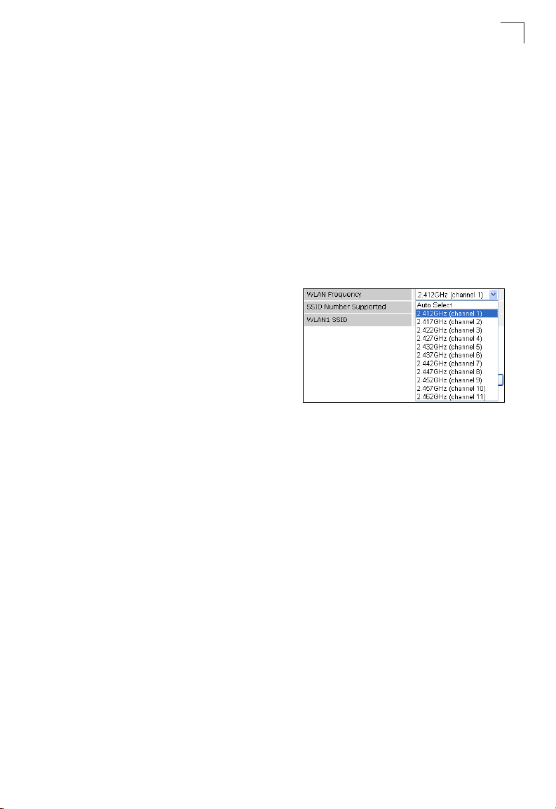
• WLAN Frequency – The radio channel
that the wireless AP/Router uses to
communicate with wireless clients. When
multiple access points are deployed in the
same area, set the channel on
neighboring access points at least five
channels apart to avoid interference with
each other. For example, you can deploy
up to three access points in the same area
using channels 1, 6, 11. Note that wireless clients automatically set the channel to
the same as that used by the wireless AP/Router to which it is linked. Selecting
Auto Select enables the wireless AP/Router to automatically select an unoccupied
radio channel. (The supported channels are dependent on the country code
setting.)
• SSID Number Supported – The number of wireless network interfaces (SSIDs)
supported on the device. (Default: 1; Ranage: 1 or 2)
• WLAN1 SSID / WLAN2 SSID – The name of the wireless network service provided
by the VAP. Clients that want to connect to the network must set their SSID to the
same as that of the VAP interface. (Default: “mr3305a1” for WLAN1; “mr3305a2”
for WLAN2; Range: 1-32 characters)
• Submit – Saves and enables the Basic Wireless Setting configuration.
• Reset – Restores the previous Basic Wireless Setting configuration information.
5
5-23
Page 28
System Configuration
5
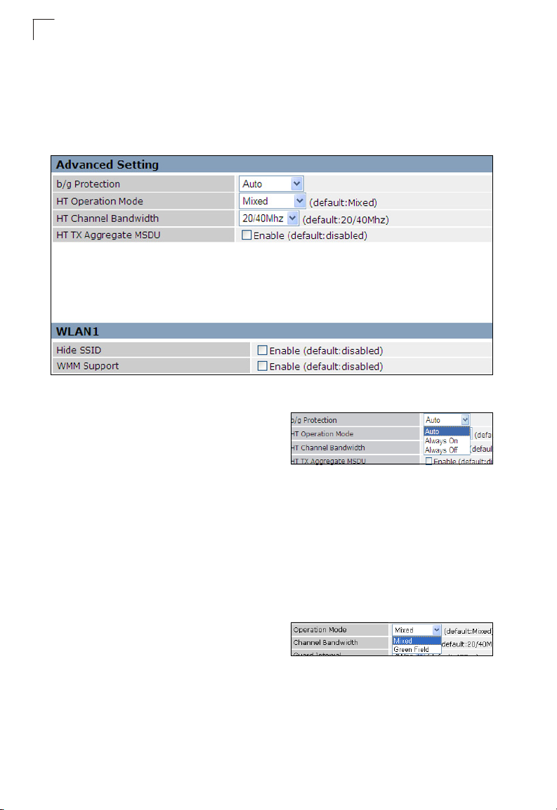
Advanced Settings
The Advanced Setting page allows you to configure the more advanced radio
settings, many of which are enabled by default.
Click “Wireless Settings” followed by “Advanced Setting.”
Figure 5-18. Advanced Radio Settings
• b/g Protection – Enables a backward
compatible protection system for
802.11b clients. There are three modes.
(Default: Auto):
- Auto: The wireless AP/Router enables its protection mechanism for 802.11b
clients when they are detected in the network. When 802.11b clients are not
detected, the protection mechanism is disabled.
- Always On: Forces the unit to always use protection for 802.11b clients,
whether they are detected in the network or not.
- Always Off: Forces the unit to never use protection for 802.11b clients. This
prevents 802.11b clients from connecting to the network.
Note: Enabling “Always On” b/g Protection can slow throughput for 802.11g/n clients by
as much as 50%.
• HT Operation Mode – Packets from
802.11n clients are referred to as High
Throughput (HT) Greenfield packets, in
other words packets that can be transmitted at rates of up to 300 Mbps assuming
that HT Channel Bandwidth is set to 20/40Mhz, see HT Channel Bandwidth next
page.
Note: Some 802.11n wireless clients may be capable of transmission rates of up to
600 Mbps, however the wireless AP/Router will only be able to connect to them at
a maximum transmission rate of 300 Mbps.
5-24
Page 29

Wireless Settings
802.11b/g packets are referred to as non-HT packets, being transmitted at lower
throughput rates. HT mixed format frames contain a preamble compatible with the
non-HT receivers.
HT Greenfield frames do not contain a non-HT compatible part. Support for HT
Greenfield format is optional. An HT station that does not support the reception of
an HT Greenfield format frame must be able to detect that an HT Greenfield format
frame is an HT transmission (as opposed to a non-HT transmission). In this case
the receiver must decode the high throughput signal (HT-SIG) in the packet header
and determine if the HT-SIG cyclic redundancy check (CRC) passes.
(Default: Mixed)
• HT Channel Bandwidth – The wireless
AP/Router provides a channel bandwidth
of 40 MHz by default giving an 802.11g
connection speed of 108 Mbps (sometimes referred to as Turbo Mode) and a
802.11n connection speed of up to 300 Mbps. Setting the HT Channel Bandwidth
to 20 MHz slows connection speed for 802.11g and 802.11n to 54 Mbps and 74
Mbps respectively and ensures backward compliance for slower 802.11b devices.
(Default: 20/40Mhz)
• HT TX Aggregate MSDU – This option enables Mac Service Data Unit (MSDU)
aggregation. (Default: Enabled)
WLAN1~WLAN2 — Stipulates settings specific to each VAP interface.
• Hide SSID – Hiding the SSID of the VAP increases security of the network but does
not allow clients to detect your presence on the network and requires that clients
already know your SSID. (Default: Disabled)
• WMM Support – Wi-Fi Multimedia (WMM), also known as Wireless Multimedia
Extensions (WME), is a Wi-Fi Alliance interoperability certification. It provides basic
Quality of Service (QoS) features for IEEE 802.11 wireless network.
Enabling WMM support provides prioritization of Wi-Fi data packets on four
categories voice, video, best effort, and background. (Default: Enabled)
• Save – Saves and enables the Advanced Wireless Setting configuration.
• Cancel – Restores the previous Advanced Wireless Setting configuration
information.
5
5-25
Page 30

System Configuration
5
WLAN Security
The wireless AP/Router’s wireless interface is configured by default as an “open
system,” which broadcasts a beacon signal including the configured SSID. Wireless
clients with a configured SSID of “ANY” can read the SSID from the beacon, and
automatically set their SSID to allow immediate connection to the wireless network.
To improve wireless network security, you have to implement two main functions:
• Authentication – It must be verified that clients attempting to connect to the network
are authorized users.
• Traffic Encryption – Data passing between the unit and clients must be protected
from interception and eavesdropping.
For a more secure network, the wireless AP/Router can implement one or a
combination of the following security mechanisms:
• Wired Equivalent Privacy (WEP)
• IEEE 802.1X
• Wi-Fi Protected Access (WPA) or WPA2
The security mechanisms that may be employed depend on the level of security
required, the network and management resources available, and the software
support provided on wireless clients.
WLAN1 and WLAN2 Security
The wireless AP/Router supports two virtual access point (VAP) interfaces referred
to as WLAN1 and WLAN2. Each VAP functions as a separate access point, and can
be configured with its own security settings.
Note: WDS settings may only be configured for WLAN1, See “WDS Settings” on
page 5-33. WLAN2 only operates as an access point service.
Note: Configuring WLAN1 to operate in Bridge mode automatically disables WLAN2.
Click "Wireless Settings" followed by either "WLAN1 Security" or "WLAN2 Security."
5-26
Page 31

Figure 5-19. WLAN1 Settings
Wireless Settings
5
5-27
Page 32

System Configuration
5
Figure 5-20. WLAN2 Settings
5-28
Page 33

Wireless Settings
Security Settings — The security settings determine the authentication mode and
enable WEP keys.
• Authentication Mode – Configures the
authentication mode used by clients.
(WLAN1/WLAN2 Defaults: Open)
- Open: Open-system authentication
accepts any client attempting to connect
the wireless AP/Router without verifying
its identity. In this mode the default
encryption type is "None."
- Shared: The shared-key approach uses
Wired Equivalent Privacy (WEP) to verify
client identity by distributing a shared key
to clients before attempting
authentication.
- WEP Auto: Allows WLAN clients to
associate using Open-WEP (uses WEP
for encryption only) or Shared-WEP (
uses WEP for authentication and
encryption). If enabled, you must
configure at least one key for the VAP
interface and all its clients. Wired
Equivalent Privacy (WEP) provides a
basic level of security, preventing unauthorized access to the network and
encrypting data transmitted between wireless clients and the wireless AP/
Router. WEP uses static shared keys (fixed-length hexadecimal or
alphanumeric strings) that are manually distributed to all clients that want to
use the network.
- WPA Personal or WPA2 Personal: The
WPA or WPA2 Personal mode uses a
common password phrase, called a
Pre-Shared Key, that must be manually
distributed to all clients that want to
connect to the network. Specify a key as
an easy-to-remember form of letters and
numbers. The WPA Preshared Key can be input as ASCII string (8-63
characters) or Hexadecimal format (length is 64). All wireless clients must be
configured with the same key to communicate with the VAP interface.
5
5-29
Page 34

System Configuration
5
- WPA Enterprise or WPA2 Enterprise:
The WPA Enterprise mode uses IEEE
802.1X as its basic framework for user
authentication and dynamic key
management. IEEE 802.1X access security uses Extensible Authentication
Protocol (EAP) and requires a configured RADIUS authentication server to be
accessible in the enterprise network. If you select WPA or WPA2 Enterprise
mode, be sure to configure the RADIUS settings. See “RADIUS” on page 5-32
for more information.
- WPA/WPA2 Personal: The WPA/
WPA2 Personal Mode allows both
WPA and WPA2 clients to join the
network. The WPA Preshared Key can
be input as ASCII string (8-63
characters) or Hexadecimal format
(length is 64). All wireless clients must be configured with the same key to
communicate with the VAP interface.
- WPA/WPA2 Enterprise: Defines a
transitional mode of operation for
networks moving from WPA security to
WPA2. WPA/WPA2 Enterprise Mode
allows both WPA and WPA2 clients to
associate to a common SSID interface. In WPA/WPA2 mixed mode, the unicast
encryption cipher (TKIP or AES-CCMP) is negotiated for each client. The access
point advertises its supported encryption ciphers in beacon frames and probe
responses. WPA and WPA2 clients select the cipher they support and return the
choice in the association request to the access point. For mixed-mode operation,
the cipher used for broadcast frames is always TKIP. WEP encryption is not
allowed.
• Encryption Type – Selects the data encryption type to use. (Default: determined
by the Authentication Mode selected)
- None: Disables data encryption.
- WEP: Selects WEP keys for data
encryption.
- TKIP: Uses Temporal Key Integrity
Protocol (TKIP) keys for encryption. WPA specifies TKIP as the data encryption
method to replace WEP. TKIP avoids the problems of WEP static keys by
dynamically changing data encryption keys.
- AES: Uses Advanced Encryption Standard (AES) keys for encryption. WPA2
uses AES Counter-Mode encryption with Cipher Block Chaining Message
Authentication Code (CBC-MAC) for message integrity. The AES
Counter-Mode/CBCMAC Protocol (AES-CCMP) provides extremely robust data
confidentiality using a 128-bit key. Use of AES-CCMP encryption is specified as
a standard requirement for WPA2. Before implementing WPA2 in the network,
be sure client devices are upgraded to WPA2-compliant hardware.
5-30
Page 35

Wireless Settings
- TKIP/AES: Uses either TKIP or AES keys for encryption. WPA/WPA2 mixed
modes allow both WPA and WPA2 clients to associate to a common SSID
interface. In mixed mode, the unicast encryption cipher (TKIP or AES-CCMP) is
negotiated for each client.
• Default Key ID – Sets the WEP key used
for authentication.
(Default: 1; Range: 1~4)
• Key 1 ~ Key 4 – Sets WEP key values.
The user must first choose between ASCII
or Hexadecimal keys. At least one key
must be specified. Each WEP key has an
index number. The selected key is used for authentication and encryption on the
VAP interface. Enter key values that match the key type and length settings.
Standard keys are either 5 or 13 alphanumeric characters; or 10 or 26 hexadecimal
digits.
(Default: ASCII, no prese
• WPA Group-Key ReKey Method – WPA
Rekeying is an extra security measure
whereby the broadcast WPA authentication
key is automatically changed after a certain
time period or after a certain number of packets have been sent. (Default:
Disabled)
• WPA Group-Key ReKey Interval – The
elapsed time after which the wireless AP/
Router will change the unicast WPA
authentication key. (Default: 0; Range:
0~67108864)
• WPA2 Pairwise Master Key Cache
Interval – The elapsed time after which the
wireless AP/Router will delete the WPA2
master keys from its security association
cache.
t value)
5
• WPA2 Pre-Authentication Support – Each time a client roams to another access
point it has to be fully re-authenticated. This authentication process is time
consuming and can disrupt applications running over the network. WPA2 includes
a mechanism, known as pre-authentication, that allows clients to roam to a new
access point and be quickly associated. The first time a client is authenticated to a
wireless network it has to be fully authenticated. When the client is about to roam
to another access point in the network, the access point sends pre-authentication
messages to the new access point that include the client’s security association
information. Then when the client sends an association request to the new access
point, the client is known to be already authenticated, so it proceeds directly to key
exchange and association. Pre-authentication support attaches a security flag to
the packet header. (Default: Disabled)
5-31
Page 36

System Configuration
5
RADIUS
Remote Authentication Dial-in User Service (RADIUS) is an authentication protocol
that uses software running on a central server to control access to RADIUS-aware
devices on the network. An authentication server contains a database of user
credentials for each user that requires access to the network.
A RADIUS server must be specified for the access point to implement IEEE 802.1X
network access control and Wi-Fi Protected Access (WPA) wireless security.
Click "WLAN1/WLAN2 Security" and be sure that an "Enterprise" mode is selected.
Note: This guide assumes that you have already configured RADIUS server(s) to
support the access point. Configuration of RADIUS server software is beyond the
scope of this guide, refer to the documentation provided with the RADIUS server
software.
Figure 5-21. RADIUS Settings
RADIUS Setting — Configures RADIUS server settings.
Note: RADIUS settings only apply to WPA, WPA2, or WPA/WPA2 Enterprise
modes.
• RADIUS Server Network – Use the
RADIUS Server Network options to
specify if the server is located on the local
area network, or wide area network.
(Default: WAN)
• RADIUS Server Address – Specifies the IP address of the RADIUS server.
• RADIUS Server Port – The User Datagram Protocol (UDP) port number used by
the RADIUS server for authentication messages. (Range: 1024-65535;
Default: 1812)
• RADIUS Server Key – A shared text string used to encrypt messages between the
access point and the RADIUS server. Be sure that the same text string is specified
on the RADIUS server. Do not use blank spaces in the string.
(Maximum length: 20 characters)
5-32
Page 37

Wireless Settings
WDS Settings
The WLAN1 radio interface can be configured to operate in a mode that allows it to
forward traffic directly to other access point units. To set up links between access
point units, you must configure the Wireless Distribution System (WDS) forwarding
table by specifying the wireless MAC address of all units to which you want to
forward traffic.
Traffic forwarded to WDS links is automatically converted to 802.11 four-address
format frame. This uses the MAC addresses of the station and that of the AP
connected to it on the transmitting LAN, and the MAC addresses of the AP
functioning as a wireless repeater/bridge and that of the station connected to it on a
neighboring LAN in the 802.11 frame header. Ethernet traffic follows a three-address
format that is reconstructed for WDS transmission. The wireless AP/Router will
reconstruct the frame format upon receival and transmission using the criteria of the
receiving and forwarding port location and whether it is Ethernet or wireless in type.
Note: The wireless AP/Router does not support the spanning tree algorithm. WDS links
should be configured appropriately to avoid causing loops on the network.
Up to four WDS links can be specified for each unit in the WDS network.
The WDS link can be configured in the following combinations:
1. Both two units are configured as Router Mode
2. One unit is Router Mode and one unit is AP Bridge Mode
3. Both two units are configured as AP Bridge Mode
5
When both units are set to Router Mode, be sure to check these settings:
• Be sure each unit is configured with a different LAN IP address.
• Be sure that only one unit has Internet access on its WAN port.
• Be sure the DHCP server is enabled only on one unit. If one unit is providing
Internet access, enable the DHCP server on that unit.
Note: WDS Settings only apply to WLAN1. WLAN2 is pre-configured to AP mode unless
WLAN1 is configured to act as a bridge, in which case WLAN2 is disabled.
Figure 5-22. WDS Settings
5-33
Page 38

System Configuration
5
WDS Setting — Configures WDS related parameters. Up to four MAC addresses
can be specified for each unit in the WDS network. WDS links may either be
manually configured (Bridge and Repeater modes) or auto-discovered (Lazy mode).
• WDS – Selects the WDS mode of WLAN1. (Default: Disabled)
- Disabled: WDS is disabled.
- Bridge: Operates as a standard bridge that forwards traffic between WDS links
(links that connect to other AP/wireless bridges, or units in Repeater or Lazy
mode) and an Ethernet port. Only data destined for stations which are known to
be on the peer Ethernet link, multicast data or data with unknown destinations,
need to be forwarded through the WDS link. The Bridge mode does not transmit
a beacon, unlike the other three modes. In this mode the wireless AP/Router
may also function as a repeater.
Note: Enabling “Bridge” mode disables WLAN2.
- Repeater – Operates as a wireless repeater, extending the range for remote
wireless clients and connecting them to an AP connected to the wired network.
WDS peers must be registered with the wireless AP/Router. Repeater mode
also supports the dual capability of the VAP functioning as an AP. In this mode,
traffic is not forwarded to the Ethernet port from the radio interface. In Repeater
mode the wireless AP/Router transmits a beacon.
- Lazy – Operates in an automatic mode that detects and learns WDS peer
addresses from received WDS four-address format frame packets, without the
need to configure a WDS MAC list entry. This feature allows the wireless AP/
Router to associate with other wireless AP/Routers in the network and use their
WDS MAC list. In Lazy mode the wireless AP/Router sends a beacon.
• WDS Encryption Type – Sets the WDS encryption type, the options for which are
determined by the Authentication Mode and the Encryption Type selected in the
Security Settings.
Note: When WDS is disabled or the WDS Encryption Type is set to "none," WDS
encryption is also disabled.
- When Authentication Mode is set to Open, Shared, or WEP auto; WEP is the
only WDS encryption type.
- When Authentication Mode is set to WPA Personal, or WPA2 Personal, the
WDS encryption type may be TKIP or AES.
- None: Disables WDS encryption.
- WEP: Uses WEP keys for data
encryption.
- TKIP: Uses Temporal Key Integrity
Protocol (TKIP) keys for encryption as a
replacement for WEP. TKIP avoids the
problems of WEP static keys by dynamically changing data encryption keys.
- AES: Uses Advanced Encryption Standard (AES) keys for encryption. Use of
AES-CCMP encryption is specified as a standard requirement for WPA2. Before
implementing WPA2 in the network, be sure client devices are upgraded to
WPA2-compliant hardware.
5-34
Page 39

Wireless Settings
- TKIP/AES: Use both TKIP and AES keys for encryption. WPA2 defines a
transitional mode of operation for networks moving from WPA security to
WPA2.WPA2 Mixed Mode allows both WPA and WPA2 clients to associate to a
common SSID interface. In mixed mode, the unicast encryption cipher (TKIP or
AES-CCMP) is negotiated for each client.
• WDS WPA/WPA2 Pre-Shared Key – This option is available only when
Authentication Mode is set to WPA Personal, WPA2 Personal or WPA/WPA2
Personal. Enter a key as an easy-to-remember form of letters and numbers. The
WDS WPA/WPA2 Preshared Key can be input as ASCII string (8-63 characters)
or Hexadecimal format (length is 64). Other bridge units must be configured with
the same key to communicate with this unit.
• WDS MAC List – The physical layer
address of other bridge units for which this
unit communicates as a network node.
(12 hexadecimal digits in the form
“xx:xx:xx:xx:xx:xx”)
Note: In WDS Lazy mode any entries in the WDS MAC List are redundant because the
MAC is pre-configured to 00:00:00:00:00:00.
5
5-35
Page 40

System Configuration
5
MAC Access Control Lists
Wireless clients can be authenticated for network access by checking their MAC
address against a local database configured on the wireless AP/Router. You can
configure a list of up to 32 wireless client MAC addresses in the filter list to either
allow or deny network access. MAC ACL configuration is the same for both WLAN1
and WLAN2.
Figure 5-23. MAC Filter
WLAN1/WLAN2 MAC Access Control Setting — Configures all MAC ACL
parameters. (Maximum 64 entries are allowed.)
• MAC Access Policy – The MAC
address filter can be configured to
allow or deny network access to
listed clients. Select "Allow All but Reject those on MAC List" to permit access from
all MAC addresses except those on the ACL list, or "Reject All but Allow those on
MAC List" to block access from all MAC addresses except those on the ACL list.
(Default: Disabled)
•Submit – Implements the selected MAC Access Policy.
• Reset – Restores the previous MAC Access Policy configuration information.
•Enable – Activates the MAC address into the ACL.
• MAC Address – MAC Address to filter, specified in the form of 12 hexadecimal
digits, “xx:xx:xx:xx:xx:xx”.
• Description – An optional parameter to help identify the selected MAC address.
(Range: 1~16 characters)
5-36
Page 41

Wireless Settings
• Action – Specifies an action to take on the MAC ACL filtering configuration.
- Change: By selecting a MAC ACL entry from the table its parameters display in
an editable form. Click "Change" to save parameters once you have updated
them.
- Add: Adds a newly configured MAC ACL entry to the list.
- Edit: Click "Edit" to highlight a configured MAC ACL filtering rule for changing its
parameters.
- Delete: Deletes a MAC entry from the list.
Associated Client List — Lists the MAC addresses of wireless clients currently
associated to the wireless AP/Router.
•MAC – A wireless client MAC address.
• Description – An optional parameter that helps identify the MAC address of the
associated client.
5
5-37
Page 42

System Configuration
5
Wi-Fi Protected Setup (WPS)
Wi-Fi Protected Setup (WPS) is designed to ease installation and activation of
security features in wireless networks. WPS has two basic modes of operation,
Push-button Configuration (PBC) and Personal Identification Number (PIN). The
WPS PIN setup is optional to the PBC setup and provides more security. The WPS
button on the wireless AP/Router can be pressed at any time to allow a single device
to easily join the network.
Note: WPS settings only apply to WLAN1.
The WPS Settings page includes configuration options for setting WPS device PIN
codes and activating the virtual WPS button.
Figure 5-24. WPS Settings
WPS Settings — Enables WPS, locks security settings, and refreshes WPS
configuration information.
• WiFi Protected Setup – Enables WPS. (Default: Enabled)
5-38
Page 43

Wireless Settings
• Lock Security Setting – Enabling this setting and clicking “Submit” or “Reset”
allows the wireless AP/Router to retain the previous WPS negotiated security
setup after a reboot or power off. Upon booting the unit will not re-authenticate
clients that were retained in memory. Only new clients will require authentication.
(Default: Disabled)
• Submit – Enables the WPS configuration.
• Reset – Restores the previous WPS configuration information.
AP Security Information — Provides detailed WPS statistical information.
• WPS Configured – States if WPS for wireless clients has been configured for this
device. (Default: no)
• WPS Status – Displays if there is currently any WPS traffic connecting to the
wireless AP/Router. (Options: Start WSC Process; Idle; Default: Idle)
• SSID – The service set identifier for WLAN1. (Default: mr3305a1)
• Auth Mode – The method of authentication used. (Default: Open)
• Encryption Type – The encryption type used for WLAN1. (Default: None)
• WPAPSK – Displays the pre-shared key if WPA/WPA2 has been enabled.
• Refresh – Refreshes the AP Security Information statistics.
WPS Config — Configures WPS settings for the wireless AP/Router.
• WPS Mode – The wireless AP/Router
can be set as a registrar (master) device
or an enrollee (client) device:
- as Registrar: When the wireless AP/Router is set as the registrar device, enter
the PIN code/s of the enrollee device/s and click “start WPS Config" to add the
client/s to the network.
Note: When the wireless AP/Router is the registrar device, the enrollee device can join
the network by entering the wireless AP/Router’s PIN code “61773981.”
5
- as Enrollee: When the wireless AP/Router is set as the enrollee device, the
default PIN-Code for the unit is displayed. Click “start WPS Config" to join the
network.
• WPS Config Method – Selects between
methods of broadcasting the WPS
beacon to network clients wanting to join
the network:
- PIN: The wireless AP/Router, along with other WPS devices, such as notebook
PCs, cameras, or phones, all come with their own eight-digit PIN code. When
one device, the WPS enrollee, sends a PIN code to the wireless AP/Router, it
becomes the WPS registrar. After configuring PIN-Code information you must
press “start WPS Config" to send the beacon, after which you have up to two
minutes to activate WPS on devices that need to join the network.
5-39
Page 44

System Configuration
5
- PBC: This has the same effect as pressing the physical WPS button that is
located on the front of the wireless AP/Router. After checking this option and
clicking “Start WPS Config” you have up to two minutes to activate WPS on
devices that need to join the network.
• Add Enrollee PIN Code – In Registrar mode enter the PIN Code for the WDS
device that wants to join the network.
• PIN Code of this AP – In Enrollee mode this displays the PIN Code for the wireless
AP/Router. The default is exclusive for each unit.
• Start WPS Config – Sends a handshake beacon to devices wanting to join the
network, for a duration of two minutes.
5-40
Page 45

Routing
Routing
Routing setup allows a manual method that is used to set up routing between
networks. The network administrator configures static routes in a router by entering
routes directly into the routing table of a router. Static routing has the advantage of
being predictable and easy configuration.
Static Route
This screen is used to manually configure static routes to other IP networks,
subnetworks, or hosts. Click "Network Settings" followed by “static Route."
(Maximum 32 entries are allowed.)
Figure 5-25. Static Route (Router mode)
• Enable – Enables the configured route. (Default: Disabled)
• Target – A destination network or specific host to which packets can be routed.
• Netmask – The subnetwork associated with the destination. This is a template that
identifies the address bits in the destination address used for routing to specific
subnets. Each bit that corresponds to a “1” is part of the network/subnet number;
each bit that corresponds to “0” is part of the host number.
• Gateway – The IP address of the router at the next hop to which matching frames
are forwarded.
• Action – Specifies an action to take on a static route.
- Change: By selecting a configured route from the routing table its parameters
display in an editable form. Click “Change” to save parameters once you have
updated them.
- Add: Adds a newly configured route to the list.
- Edit: Click "Edit" to highlight an entry in the static MAC list for changing its
parameters.
- Delete: Deletes a static route from the list.
5
5-41
Page 46

System Configuration
5
Dynamic Route
The wireless AP/Router supports RIP 1 and RIP 2 dynamic routing protocol. Routing
Information Protocol (RIP) is the most widely used method for dynamically
maintaining routing tables. RIP uses a distance vector-based approach to routing.
Routes are chosen to minimize the distance vector, or hop count, which serves as a
rough estimate of transmission cost. Each router broadcasts its advertisement every
30 seconds, together with any updates to its routing table. This allows all routers on
the network to build consistent tables of next hop links which lead to relevant
subnets.
Figure 5-26. Dynamic Route (Router mode)
• WAN Interface – Specifies RIP1, RIP2, RIP1/RIP2, or disables the function for the
WAN interface.
• LAN Interface – Specifies RIP1, RIP2, RIP1/RIP2, or disables the function for the
LAN interface.
5-42
Page 47

Routing
Multicast Routing
Multicasting is used to support real-time applications such as videoconferencing or
streaming audio. A multicast server does not have to establish a separate
connection with each client. It merely broadcasts its service to the network, and any
hosts that want to receive the multicast register with their local multicast router.
Although this approach reduces the network overhead required by a multicast
server, the broadcast traffic must be carefully pruned at every multicast network
device it passes through to ensure that traffic is only passed on to the hosts that
have subscribed to the service.
This device uses IGMP (Internet Group Management Protocol) Snooping to monitor
IGMP service requests passing between multicast clients and servers, and
dynamically configure the ports that need to forward multicast traffic.
5
Figure 5-27. Multicast Route (Router mode)
IGMP Snooping — The wireless AP/Router can passively snoop on IGMP Query
and Report packets transferred between IP multicast routers and IP multicast host
groups to identify the IP multicast group members. It simply monitors the IGMP
packets passing through it, picks out the group registration information, and
configures the multicast filters accordingly.
• Enable – Enables IGMP snooping on the wireless AP/Router.
IGMP Proxy — Collects and sends multicast group membership information onto
the upstream interface based on IGMP messages monitored on downstream
interfaces, and forwards multicast traffic based on that information.
• IGMP Proxy – Enables IGMP proxy on the wireless AP/Router.
• Quick Leave – The wireless AP/Router can immediately delete a member port of
a multicast service if a leave packet is received at that port.
5-43
Page 48

System Configuration
5
WAN Multicast Routing — IP addresses of upstream multicast routers on the WAN
interface. You can add, edit, and delete IP addresses from the list.
• IP Address – Specifies an IP address to route to.
• Net Mask – Specifies a network mask.
Firewall
The wireless AP/Router provides extensive firewall protection by restricting
connection parameters to limit the risk of intrusion and defending against a wide
array of common hacker attacks.
NAT
Network Address Translation (NAT) is a standard method of mapping multiple
"internal" IP addresses to one "external" IP address on devices at the edge of a
network. For the wireless AP/Router, the internal (local) IP addresses are the IP
addresses assigned to PCs and wireless clients by the DHCP server, and the
external IP address is the IP address assigned to the WAN port.
If you configure the wireless AP/Router as a virtual server, remote users accessing
services such as web or FTP at your local site through public IP addresses can be
automatically redirected to local servers configured with private IP addresses. In
other words, depending on the requested service (TCP/UDP port number), the
wireless AP/Router redirects the external service request to the appropriate server
(located at another internal IP address).
For example, if you set Type/Public Port to TCP/80 (HTTP or web) and the Private
IP/Port to 192.168.2.2/80, then all HTTP requests from outside users will be
transferred to 192.168.2.2 on port 80. Therefore, by just entering the IP address
provided by the ISP, Internet users can access the service they need at the local
address to which you redirect them.
The more common TCP service port numbers include: HTTP: 80, FTP: 21,
Telnet: 23, and POP3: 110.
Some applications, such as Internet gaming, videoconferencing, Internet telephony
and others, require multiple connections. These applications cannot work with
Network Address Translation (NAT) enabled. If you need to run applications that
require multiple connections, use port mapping to specify the additional public ports
to be opened for each application.
Click "Network Settings" followed by "NAT."
5-44
Page 49

Firewall
5
Figure 5-28. NAT (Router mode)
NAT Setting — Enables NAT related settings.
• Network Address Translation – Enables the forwarding of TCP/UDP packets
through a NAT device.
• IPSec Pass Through – Enables tunnelling encrypted Internet Protocol Security
(IPSec) packets through a NAT device.
• PPTP Pass Through – Enables tunnelling Point-to-Point Tunneling Protocol
(PPTP) packets through a NAT device.
• L2TP Pass Through – Enables tunnelling Layer 2 Tunnelling Protocol (L2TP)
packets through a NAT device.
•SIP ALG – Allows SIP Application Layer Gateway (ALG) traversal filters to be used
to support address and port translation for certain application layer protocols.
• NetMeeting ALG – Allows NetMeeting ALG traversal filters to be used to support
address and port translation for certain application layer protocols.
• Window Messenger File Transfer ALG – Enables Window Messenger File
Transfer ALG to transmit packets through proxy servers.
5-45
Page 50

System Configuration
5
•DMZ – Enables a specified host PC on the local network to access the Internet
without any firewall protection. Some Internet applications, such as interactive
games or videoconferencing, may not function properly behind the wireless AP/
Router's firewall. By specifying a Demilitarized Zone (DMZ) host, the PC's TCP
ports are completely exposed to the Internet, allowing open two-way
communication. The host PC should be assigned a static IP address (which is
mapped to its MAC address) and this must be configured as the DMZ LAN IP.
• DMZ LAN IP – Specifies the IP address of the DMZ.
• Non-standard FTP port – Enables routing of traffic through a non-standard FTP
port.
• Submit – Saves the current NAT configuration.
• Reset – Restores the previous NAT configuration information.
Virtual Server Mapping — Using the NAT Virtual Server Mapping feature, remote
users can access different servers on your local network using your single public IP
address. (Maximum 32 entries are allowed.)
• Enable – Enables port mapping for the specified IP address. (Default: Disabled)
• WAN IP Alias – Selects an alias IP address to route traffic to and from the WAN
port. Using IP aliasing increases the traffic the WAN port can handle.
• WAN Port – Specifies the WAN port number, or a port range, for example
“4040-4080.” (Range: 1~65535)
•Protocol – Specifies the port type, TCP or UDP. (Default: TCP)
•LAN IP – The IP address of the server on the local Ethernet network. The specified
address must be in the same subnet as the wireless AP/Router and its DHCP
server address pool.
•LAN Port – Specifies the LAN port number, or a port range, for example
“4040-4080.” (Range: 1~65535)
• Action – Specifies an action to take on the virtual server map.
- Change: By selecting a configured virtual server map from the table its
parameters display in an editable form. Click "Change" to save parameters once
you have updated them.
- Add: Adds a newly configured map to the list.
- Edit: Click "Edit" to highlight a mapping rule entry in the list for changing its
parameters.
- Delete: Deletes a mapping rule from the list.
Port Trigger — Port triggering is a way to automate port forwarding in which
outbound traffic on predetermined ports ("triggering ports") causes inbound traffic to
specific incoming ports to be dynamically forwarded to the initiating host while the
outbound ports are in use. (Maximum 32 entries are allowed.)
•Enable – Enables port triggering on the specified ports. (Default: Disabled)
• Trigger Port – Specifies the outbound port, or port range, for example
“4040-4080.” (Range: 1~65535, or number1-number2)
• Trigger Type – Specifies the trigger port type, TCP or UDP. (Default: TCP)
5-46
Page 51

Firewall
•Public Port – Specifies the port to forward traffic to.
• Public Type – Specifies the forwarded port type, TCP or UDP. (Default: TCP)
• Action – Specifies an action to take on the port triggering configuration.
- Change: By selecting a configured port trigger from the table its parameters
display in an editable form. Click "Change" to save parameters once you have
updated them.
- Add: Adds a newly configured port trigger to the list.
- Edit: Click "Edit" to highlight a port trigger rule in the list for changing its
parameters.
- Delete: Deletes a port trigger rule from the list.
Port Forward — Port forwarding (sometimes referred to as tunneling) is the act of
forwarding a network port from one network node to another. This technique can
allow an external user to reach a port on a private IP address (inside a LAN) from
the outside through a NAT-enabled router. (Maximum 32 entries are allowed.)
•Enable – Enables port forwarding on the specified port. (Default: Disabled)
• Forward Port – Specifies the port through which traffic is forwarded.
• Forward Type – Specifies the forwarding port type, TCP or UDP. (Default: TCP)
• Forward IP – Specifies the IP address on the local network to allow external
access to.
• Action – Specifies an action to take on the port forwarding configuration.
- Change: By selecting a port forwarding configuration from the table its
parameters display in an editable form. Click "Change" to save parameters once
you have updated them.
- Add: Adds a newly configured port that allows forwarding in to the local area
network to the list.
- Edit: Click "Edit" to highlight a forwarding port rule in the list for changing its
parameters.
- Delete: Deletes a port forwarding rule from the list.
5
5-47
Page 52

System Configuration
5
Packet Filtering
The wireless AP/Router provides extensive firewall protection through packet
filtering.
Packet filtering restricts connection parameters to limit the risk of intrusion and
defends against a wide array of common hacker attacks. Packet filtering allows the
unit to permit, deny or proxy traffic through its ports.
Figure 5-29. Packet Filtering (Router mode)
WAN Packet Filter — Globally enables WAN packet filtering. (Default: Enabled,
maximum 32 entries are allowed.)
•Enable – Enables the filtering rule on a specified IP address and TCP/UDP port.
(Default: Disabled)
• Source IP – Specifies the IP address to block WAN traffic from.
• Destination Port – Specifies the port to block traffic from the specified WAN IP
address from reaching.
•Protocol – Specifies the destination port type, TCP or UDP. (Default: TCP)
•Block – Specifies if traffic should be blocked "Always" or configured "by Schedule."
•Day – Specifies the day or days of the week on which to block traffic.
•Time – Specifies the time of day during which to block traffic.
• Action – Specifies an action to take on the WAN packet filtering configuration.
5-48
Page 53

Firewall
- Change: By selecting a packet filtering configuration from the table its
parameters display in an editable form. Click "Change" to save parameters once
you have updated them.
- Add: Adds a newly configured packet filter that denies forwarding in to the local
area network to the list.
- Edit: Click "Edit" to highlight a packet filtering rule in the list for changing its
parameters.
- Delete: Deletes a packet filtering rule from the list.
LAN Packet Filter — Globally enables LAN packet filtering. (Default: Enabled,
maximum 32 entries are allowed.)
•Enable – Enables the filtering rule on a specified IP address and TCP/UDP port.
(Default: Enabled)
• Source IP – Specifies the IP address to block LAN traffic from.
• Destination Port – Specifies the port to block traffic from the specified LAN IP
address from reaching.
•Protocol – Specifies the destination port type, TCP or UDP. (Default: TCP)
•Block – Specifies if traffic should be blocked "Always" or configured "by Schedule."
•Day – Specifies the day or days of the week on which to block traffic.
•Time – Specifies the time of day during which to block traffic.
• Action – Specifies an action to take on the LAN packet filtering configuration.
- Change: By selecting a packet filtering configuration from the table its
parameters display in an editable form. Click "Change" to save parameters once
you have updated them.
- Add: Adds a newly configured packet filter that denies forwarding in to the local
area network to the list.
- Edit: Click "Edit" to highlight a packet filtering rule in the list for changing its
parameters.
- Delete: Deletes a packet filtering rule from the list.
MAC Packet Filter — Globally enables MAC packet filtering. (Default: Enabled,
maximum 32 entries are allowed.)
•Enable – Enables the filtering rule on a specified MAC address. (Default: Disabled)
• MAC Address – Specifies the MAC address to block traffic from.
•Block – Specifies if traffic should be blocked "Always" or configured "by Schedule."
•Day – Specifies the day or days of the week on which to block traffic.
•Time – Specifies the time of day during which to block traffic.
• Action – Specifies an action to take on the MAC packet filtering configuration.
- Change: By selecting a packet filtering configuration from the table its
parameters display in an editable form. Click "Change" to save parameters once
you have updated them.
- Add: Adds a newly configured packet filter that denies forwarding in to the local
area network to the list.
5
5-49
Page 54

System Configuration
5
- Edit: Click "Edit" to highlight a preconfigured packet filtering rule for changing its
parameters.
- Delete: Deletes a packet filtering rule from the list.
URL Filter
By filtering inbound Uniform Resource Locators (URLs) the risk of compromising the
network can be reduced. URLs are commonly used to point to websites. By
specifying a URL or a keyword contained in a URL traffic from that site may be
blocked.
Click "Network Settings" followed by "URL Filter."
Figure 5-30. URL Filtering (Router mode)
URL Filter — Globally enables URL filtering. (Default: Enabled, maximum 32 entries
are allowed.)
•Enable – Enables the filtering rule on a specified LAN IP address.
(Default: Disabled)
• Client IP – Specifies the LAN IP address that traffic should be blocked from.
• URL Filter String – Specifies either a string, or a specific website address that
traffic is to be blocked from. May be in the form of a text or number string with no
spaces, or a website address.
• Action – Specifies an action to take on the URL packet filtering configuration.
- Change: By selecting a URL filtering configuration from the table its parameters
display in an editable form. Click "Change" to save parameters once you have
updated them.
- Add: Adds a newly configured URL filter that denies forwarding in to the local
area network to the list.
- Edit: Click "Edit" to highlight a URL filtering rule in the list for changing its
parameters.
5-50
Page 55

Firewall
- Delete: Deletes a URL filtering rule from the list.
Security Setting
The Security Setting page enables intrusion detection (ID), a type of security
management system for computers and networks. An ID system gathers and
analyzes information from various areas within a computer or a network to identify
possible security breaches, which include both intrusions (attacks from outside the
organization) and misuse (attacks from within the organization). ID uses vulnerability
assessment (sometimes referred to as scanning), which is a technology developed
to assess the security of a computer system or network.
Click on "Network Settings" followed by ’security Setting."
5
Figure 5-31. Security Setting (Router mode)
• Intrusion Detection – Enables the ID system. (Default: Disabled)
• Drop Malicious Packet – Enables the ID system to work inline with incoming
traffic and drops malicious or unwanted packets. (Default: Disabled)
5-51
Page 56

System Configuration
5
Service Settings
DHCP
The wireless AP/Router includes a Dynamic Host Configuration Protocol (DHCP)
server that can assign temporary IP addresses to any attached host requesting the
service. The unit can support up to 253 local clients. Addresses are assigned to
clients from a common address pool configured on the unit. Configure an address
pool by specifying start and end IP addresses. Be sure not to include the unit's IP
address in the address pool range. Click on “Network Settings” followed by “DHCP.”
Figure 5-32. DHCP Settings (Router mode)
• DHCP Server – Enables the DHCP server. (Default: Enabled)
• Assigned DHCP IP Address – Specify the start and end IP addresses of a range
that the DHCP server can allocate to DHCP clients. Note that the address pool
range is always in the same subnet as the unit’s IP setting. The maximum clients
that the unit can support is 253.
• DHCP IP Lease Time – Select a time limit for the use of an IP address from the IP
pool. When the time limit expires, the client has to request a new IP address. The
lease time is expressed in seconds.
(Default: 86400 seconds; Range: 60~864000 seconds)
• Save – Saves the current DHCP configuration.
• Cancel – Restores the previous DHCP configuration information.
• DHCP Static Map – Maps client MAC addresses to static IP addresses. This
allows specified clients to always be assigned the same IP when they request
settings. (Maximum 32 entries are allowed.)
5-52
Page 57

Service Settings
- MAC: The physical layer address used to uniquely identify the static IP address
to be assigned to the specified client MAC address. The IP address must be in
the same subnet as the wireless AP/Router..
- IP: The static IP address to be assigned to the specified client MAC address. The
IP address must be in the same subnet as the wireless AP/Router.
- Description: An optional brief description that can be used to help identify the
client device.
- Action: Specifies changes or additions to the DHCP static map table.
- Change: By selecting an already configured DHCP static map its parameters
display in an editable form. Click “Change” to save parameters once you have
modified them.
- Add: Adds a newly configured DHCP static map to the list.
- Edit: Click “Edit” to highlight an entry in the static DHCP client list for changing
its parameters.
- Delete: Deletes a DHCP static map from the list.
• DHCP Client List – Lists information about associated DHCP clients.
- Type: Describes the type of DHCP client.
- Hostname: The hostname of the DHCP client.
- MAC: The MAC address of the DHCP client.
- IP: The IP address of the DHCP client.
- Description: Optional description of the DHCP client.
- Expire Time: The time after which the connection will expire and the DHCP
client must request a new IP address.
UPnP Setting
UPnP (Universal Plug and Play) provides inter-connectivity between devices
supported by the same standard. UPnP is based on standard Internet protocols,
such as TCP/IP, UDP, and HTTP.
Click on “Network Settings” followed by “UPnP.”
5
Figure 5-33. UPnP Setting (Router mode)
UPnP Setting — Allows the device to advertise its UPnP capabilities.
5-53
Page 58

System Configuration
5
• UPnP Internet Gate Device – Enables UPnP on the wireless AP/Router.
(Default: Disabled)
• Save – Saves the enabled UPnP configuration.
• Cancel – Restores the previous UPnP configuration information.
UPnP Map — Displays UPnP statistics.
• Remote Host – Displays the UPnP host device on the WAN.
• External Port – Displays the external WAN port from which UPnP discovery is
broadcast to the wireless AP/Router.
• Internal Client – Displays the LAN connected UPnP supporting device.
•Internal Port – Displays the LAN port to which the internal client is connected.
•Protocol – Specifies the protocol used, TCP, UDP, or HTTP.
•Duration – Displays the time the device will advertise its UPnP capabilities, after
which it must send a renewal message. It is generally expected that a device will
display an duration advertisement for 1800 seconds (30 minutes) or more.
• Description – Optional parameter that describes the device to a network
administrator.
• Refresh – Refreshes the UPnP Map statistics.
DDNS Settings
Dynamic DNS (DDNS) provides users on the Internet with a method to tie a specific
domain name to the unit’s dynamically assigned IP address. DDNS allows your
domain name to follow your IP address automatically by changing your DNS records
when your IP address changes.
The wireless AP/Router provides access to three DDNS service providers,
DynDns.org, Non-IP.com and ZoneEdit.com. To set up an DDNS account, visit the
websites of these service providers at www.dyndns.org, www.non-ip.com, or
www.zoneedit.com.
Click on "Network Settings" followed by "DDNS."
5-54
Figure 5-34. DDNS Setting (Router mode)
Page 59

Service Settings
• DDNS – Enables DDNS. (Default: Disabled)
• DDNS Server Type – Specifies the DDNS service provider, DynDns.org,
Non-IP.com, or ZoneEdit.com. (Default: DynDns.org)
• DDNS Username – Specifies your username for the DDNS service.
• DDNS Password – Specifies your password for the DDNS service.
• Confirmed Password – Prompts you to re-enter your chosen password.
• Hostname to register – Specifies the prefix to identify your presence on the DDNS
server.
• Submit – Saves and sends the enabled DDNS configuration to the DDNS server.
• Reset – Restores the previous DDNS configuration information.
System Log Settings
The wireless AP/Router supports a logging process that controls error messages
saved to memory or sent to a Syslog server. The logged messages serve as a
valuable tool for isolating wireless AP/Router and network problems.
The System Log Settings page controls the type of logging message that the
wireless AP/Router can send.
5
Figure 5-35. System Log Settings
• System Log – Enables local storage of system logs concerned with the wireless
AP/Router only. (Default: Disabled)
• Storage Type – Indicates where the
system log messages are to be stored.
(Default: RAM)
Note: System log messages stored in RAM are cleared after a reboot.
5-55
Page 60

System Configuration
5
• Log Level – Configures the minimum
severity level for event logging. The system
allows you to limit the messages that are
logged by specifying the minimum severity
level.
(Default: 4 Warning)
- 1 Alert – An error condition requiring
immediate user intervention to prevent a problem.
- 2 Critical – An error condition that may require user intervention.
- 3 Error – An error condition that does not cause significant problems with normal
operation.
- 4 Warning – An error condition that does not cause system problems but may
require attention.
- 5 Notice – A system condition that does not cause system problems but should
be noted.
- 6 Info – Informational message only.
- 7 Debug – Sends the lowest level of system log messages only. Debug
messages carry information for debugging software.
- Disabled – Disables sending of any logging messages.
• Total Log Size – Indicates the
amount of RAM or Flash memory
available for logging messages.
(Default: 10 Kbytes; Range: 10 or
20 Kbytes)
• Remote Log – Enables remote
storage of system logs on a Syslog server. (Default: Disabled)
• Remote Log Server Address – The address of the remote logging server.
(Default: your.syslog.server)
• Remote Log Server Port – The remote port to which messages are to be sent to.
(Default: 514; Range: 1~65535)
• Log to Remote and Local – Enables simultaneous logging to a remote Syslog
server and local logging on the wireless/AP Router’s RAM or Flash memory.
(Default: Disabled)
Note: Enabling Remote Logging disables local logging unless “Log to Remote and
Local” is selected.
• Submit – Saves the current system log configuration.
• Reset – Restores the previous current system log configuration.
5-56
Page 61

Service Settings
Date and Time Settings
The Date/Time page allows you to manually configure time settings or enable the
use of an NTP server.
Figure 5-36. Date and Time Settings - NTP
• Date Time Set By – Allows you to manually configure time settings or select the
use of an NTP server.
• Time Zone – Specifies the time zone in Greenwich Mean Time (GMT).
• Daylight Saving – Enables daylight savings for summertime. Daylight Saving
Time begins for most of the United States at 2:00 a.m. on the first Sunday of April.
Time reverts to standard time at 2:00 a.m. on the last Sunday of October. In the
U.S., each time zone switches at a different time. In the European Union, Summer
Time begins and ends at 1:00 a.m. GMT. It begins the last Sunday in March and
ends the last Sunday in October. In the EU, all time zones change at the same
moment. (Default: Disabled)
• NTP Update Interval – Specifies the number of hours before which the wireless
AP/Router will send for a time update from NTP servers. (Default: 24 hours;
Range 1~1000 hours)
• NTP Server 1~2 – The IP address or URL of the NTP server to be used.
• Submit – Applies the Date/Time settings.
• Reset – Restores the previous Date/Time settings.
5
5-57
Page 62

System Configuration
5
Figure 5-37. Date and Time Settings - Manual
• Date Time Set By – Allows you to manually configure time settings or select the
use of an NTP server.
• Time Zone – Specifies the time zone in Greenwich Mean Time (GMT).
• Daylight Saving – Enables daylight savings for summertime. (Default: Disabled)
• Date Value Setting – Sets the date for the wireless AP/Router in year; month; day
format.
• Time Value Setting – Sets the time for the wireless AP/Router in hour, minute;
second format.
• Submit – Applies the Date/Time settings.
• Reset – Restores the previous Date/Time settings.
5-58
Page 63

Service Settings
PING Test
The wireless AP/Router provides the function of “pinging” a specified IP address or
URL to test for connectivity.
Figure 5-38. Ping Test - success
5
Figure 5-39. Ping Test - failure
• PING Destination – The destination IP address to test.
• PING – Sends the request.
5-59
Page 64

System Configuration
5
Management Settings
The wireless AP/Router’s Management Settings menu provides the same
configuration options in both Router and AP Mode. These settings allow you to
change the operating mode, set the system time, configure a management access
password, and upgrade the system software.
Admin Accounts and Remote Administration
Management access to the wireless AP/Router is controlled through different levels
of user name and password. You can also gain additional access security by using
control filters such as ACLs and URL filters.
To protect access to the management interface, you need to configure a new
Administrator’s user name and password as soon as possible. If a new user name
and password are not configured, then anyone having access to the wireless AP/
Router may be able to compromise the unit's security by entering the default values.
Once a new Administrator has been configured, you can delete the default “admin”
user name from the system.
Management access to the wireless AP/Router through the WAN port is possible
when remote administration is enabled and the connecting HTTP, port or IP address
is configured.
5-60
Figure 5-40. Administration Settings
Page 65

Management Settings
Admin Accounts — Configures access levels, usernames and passwords.
(Maximum 32 entries are allowed.)
• Access Level – Configures the access
privileges that the user has.
- Admin: Grants administrator level
access, no restrictions.
- User: Grants user level access, some restrictions.
- Guest: Grants guest level access, configuration settings may not be changed.
Note: Pressing the Reset button on the back of the wireless AP/Router for more than
5 seconds resets the user names and passwords to the factory defaults.
• Username – The name of the user. The default names preset for access to the unit
are "root" for admin level, "user" for user level and "guest" for guest level.
(Length: 3-16 characters, case sensitive)
• Password – The password for management access. The default passwords
preset for access to the unit are identical to their user names, “root” for admin level,
“user” for user level and “guest” for guest level. (Length: 3-16 characters, case
sensitive)
• Confirm Password – Prompts you to enter the password again for verification.
• Action – Specifies an action to take on the admin account.
- Change: By selecting a user from the table its parameters display in an editable
form. Click "Change" to save parameters once you have updated them.
- Add: Adds a newly configured user to the list.
- Edit: Click "Edit" to highlight a configured user for changing its parameters.
- Delete: Deletes a user entry from the list.
Remote Accounts — Configures remote management access for the wireless AP/
Router.
• Remote administration – Enables remote administration. (Default: Enabled)
• HTTP port for remote – Specifies the HTTP port for remote access. (Default:
8888; Range: 1~65535)
• Remote administration only from IP – Configures an IP address from which to
manage the unit. Using an address of 0.0.0.0 enables remote management access
from any IP address and is therefore recommended that the user change the
default setting. (Default: 0.0.0.0)
• Update – Updates the remote administration information.
Reboot – Click the button to reboot the wireless AP/Router.
5
5-61
Page 66

System Configuration
5
Config Settings
The Config Setting page allows you to save the wireless AP/Router’s current
configuration or restore a previously saved configuration back to the device
Figure 5-41. Config Settings
• Save – Saves the current configuration locally.
• Restore – Restores a previously saved configuration from a specified file.
• Factory Default – Restores the factory defaults.
• View Current Config – Opens a display window that details parameters about the
current configuration.
5-62
Figure 5-42. View Current Config Settings
Page 67

Management Settings
Firmware Upgrade
You can update the wireless AP/Router firmware by using the Firmware Update
facility.
Figure 5-43. View Current Config Settings
Firmware Update — Allows you to upload new firmware manually by specifying a
file path. Make sure the firmware you want to use is on the local computer by
clicking Browse to search for the firmware to be used for the update.
• Browse – Opens a directory on the local hard drive for specifying the path of file
required for uploading.
• Upload – Starts the upload procedure.
5
5-63
Page 68

System Configuration
5
Status Information
The Information pages display details on the current configuration and status of the
wireless AP/Router, including associated wireless stations and event log messages.
Note: The Status Information pages will display different statistics depending on the
mode selected, AP or Router. Please refer to “Installation” on page 2-1 for details.
System Information
The System Information page displays basic system information as well as
Management IP, WAN, LAN, WLAN and WDS settings. The displayed settings are
for status information only and are not configurable on this page. This information is
split into the four sections that follow.
Click "Information", followed by “System Information" and scroll to the relevant
section.
Figure 5-44. System Information - Basic Information
System — Displays the basic system information in both AP and Router modes:
• Device Mode – Displays the hardware setting determined by the switch on the
base of the unit.
• Model Name – The device name and model number.
• Firmware Version – The version number of the current wireless AP/Router
software.
•Host Name – The web address assigned as an alias for the wireless AP/Router,
enabling the device to be uniquely identified on the network.
• System Date – The current date and time set for the wireless AP/Router, in the
form year; month; day; hours; minutes; seconds.
•Up Time – Length of time the management agent has been up, specified in hours
and minutes.
5-64
Page 69

Status Information
Figure 5-45. System Information - WAN Statistics (Router mode)
WAN — Displays the basic WAN information:
• Ethernet Speed – The connection speed of the WAN port.
• Ethernet MAC Address – The physical layer address for the Ethernet WAN port.
• IP Assignment – Indicates if the IP address has been manually configured or
assigned by DHCP.
• DHCP Client – Displays if the wireless AP/Router is acting as a DHCP client.
• DHCP Connection Established Time – If connected as a DHCP client it displays
the duration the other device has been connected
• DHCP Connection Expire Time – If connected as a DHCP client it displays the
length of time before which the connection will expire.
• DHCP Server Address – If connected to a DHCP server it displays the address of
the server.
•IP Address – IP address of the WAN port for this device.
• Subnet Mask – The mask that identifies the host address bits used for routing to
the WAN port.
•MTU – Indicates the Maximum Transmission Unit (MTU), the largest packet size
allowed to be transmitted over the WAN port.
• Gateway Address – The default gateway is the IP address of the router for the
wireless AP/Router, which is used if the requested destination address is not on
the local subnet
• DNS 1 (Primary) / DNS 2 (Secondary) – The IP address of Domain Name Servers
on the network. A DNS maps numerical IP addresses to domain names and can
be used to identify network hosts by familiar names instead of the IP addresses.
5
Figure 5-46. System Information - LAN Statistics (Router mode)
LAN — Displays the basic LAN information:
5-65
Page 70

System Configuration
5
• MAC Address – The shared physical layer address for the wireless AP/Router’s
LAN ports.
• IP Address – The IP address configured on the wireless AP/Router.
• Subnet Mask – The mask that identifies the host address bits used for routing to
the LAN port.
• DHCP Server Function – Indicates the DHCP server status.
Figure 5-47. System Information - Management IP Statistics (AP mode)
Management IP related information — Displays basic management IP information
settings:
• MAC Address – The shared physical layer address for the wireless AP/Router’s
LAN and WAN ports.
• IP Address – The IP address configured on the wireless AP/Router.
• Subnet Mask – The mask that identifies the host address bits used for routing to
the LAN port.
• DHCP Server Function – Indicates the DHCP server status.
Figure 5-48. System Information - WLAN Statistics
WLAN — Displays the basic WLAN information:
• WLAN Status –Displays if the radio is enabled or disabled.
• Country – The country for which the wireless AP/Router has been set for use.
• WLAN Mode – Displays the radio mode being used.
• Frequency – The channel frequency being used by the radio.
•WLAN1 SSID – The service set identifier for WLAN1. (Default: mr3305a1)
• WLAN1 MAC Address – The physical layer address for WLAN1.
Figure 5-49. System Information - WDS Statistics
5-66
Page 71

Status Information
WDS — Displays the basic WDS information.
Note: WDS information only applies to WLAN1.
•WDS Mode – The WDS mode in which WLAN1 is set to operate.
• WDS Encryption Type – The encryption type used by WLAN1.
• WDS MAC List – Displays any entries in the WDS MAC list. (Maximum: 4)
Routing Table
This page displays the information necessary to forward a packet along the best
path toward its destination. Each packet contains information about its origin and
destination. When a packet is received, a network device examines the packet and
matches it to the routing table entry providing the best match for its destination. The
table then provides the device with instructions for sending the packet to the next
hop on its route across the network.
Note: The Routing Table is only available when the wireless AP/Router is set to Router
Mode.
Figure 5-50. Routing Table (Router Mode)
• Destination – Displays all destination networks or specific hosts to which packets
can be routed.
• Gateway – Displays the IP address of the router at the next hop to which matching
frames are forwarded.
•Netmask – Displays the subnetwork associated with the destination.
• Flags – Possible flags include: U: route is up, H: target is a host, G: use gateway,
C: cache entry, !: Reject route.
• Metric – A number used to indicate the cost of the route so that the best route,
among potentially multiple routes to the same destination, can be selected.
• Ref – Number of references to this route.
• Use – Count of lookups for the route.
• Iface – Interface to which packets for this route will be sent.
5
Packet Statistics
The device keeps statistics of the data traffic that it handles. You are able to view the
amount of Received and Sent packets that passes through the device on both the
WAN port and the LAN ports. The traffic counter will reset when the device is
rebooted.
5-67
Page 72

System Configuration
5
Figure 5-51. Packet statistics
• Interface – Displays the name of the interface the packet statistics relate to.
• Recv Bytes – The total number of bytes received on the interface.
•Send Bytes – The total number of bytes sent from the interface.
• Recv Pkts – The total number of packets received on the interface.
•Send Pkts – The total number of packets sent from the interface.
• Recv Errs – The total number of inbound packets that could not be delivered
through the interface due to errors.
• Send Errs – The total number of outbound packets that could not be delivered
through the interface due to errors.
5-68
Page 73

Status Information
System Logs
The wireless AP/Router supports a logging process that controls error messages
saved to memory or sent to a Syslog server. The logged messages serve as a
valuable tool for isolating wireless AP/Router and network problems.
The Events Log page displays the latest messages logged in chronological order,
from the newest to the oldest. Log messages saved in the wireless AP/Router’s
memory are erased when the device is rebooted.
Figure 5-52. Syslog Settings
Priority — Select the priority level of syslog
messages to be sent to the wireless AP/
Router. (Default: All)
•All – Displays all logging messages.
•Alert – An error condition requiring
immediate user intervention to prevent a
problem.
• Critical – An error condition that may require user intervention.
• Error – An error condition that does not cause significant problems with normal
operation.
• Warning – An error condition that does not cause system problems but may
require attention.
•Notice – A system condition that does not cause system problems but should be
noted.
•Info – Informational message only.
• Debug – Displays the lowest level of system log messages only. Debug messages
carry information for debugging software.
Category — Select the category of syslog
messages sent to the wireless AP/Router.
(Default: All)
• All – Displays all categories of message.
•Kernel – Displays system log messages concerned with Linux Kernel base code
problems only.
5
5-69
Page 74

System Configuration
5
• Process – Displays system log messages concerned with all other process other
than the Linux Kernel, including communication through the wireless AP/Router’s
ports.
• Refresh – Refreshes the System Log display to display the most recent messages
received.
• Date Time – The date and time of receival of the system log message.
• Facility Priority – The priority level of the system log message.
• Category – The category of system log message.
•Info – Additional informative content that may help isolate the cause of the problem
that prompted the system log message.
5-70
Page 75

Appendix A: Troubleshooting
Check the following items before you contact local Technical Support.
1. If wireless clients cannot access the network, check the following:
• Be sure the access point and the wireless clients are configured with the same
Service Set ID (SSID).
• If authentication or encryption are enabled, ensure that the wireless clients are
properly configured with the appropriate authentication or encryption keys.
2. If the wireless AP/Router cannot be configured using a web browser:
• Be sure to have configured the access point with a valid IP address, subnet
mask and default gateway.
• If you are connecting to the wireless AP/Router through the wired Ethernet
interface, check the network cabling between the management station and the
wireless AP/Router. If you are connecting to wireless AP/Router from a
wireless client, ensure that you have a valid connection to the wireless AP/
Router.
3. If you forgot or lost the password:
• Set the wireless AP/Router to its default configuration by pressing the reset
button on the bottom panel for 5 seconds or more. Connect to the web
management interface using the default IP address 192.168.1.254. Then set
up a new user name and password to access the management interface.
4. If all other recovery measure fail, and the wireless AP/Router is still not
functioning properly, take any of these steps:
• Reset the wireless AP/Router’s hardware using the web interface or through
a power reset.
• Reset the wireless AP/Router to its default configuration by pressing the reset
button on the back panel for 5 seconds or more. Connect to the web
management interface using the default IP address 192.168.1.254, then
setup a user name and password.
A-1
Page 76

Troubleshooting
A
Diagnosing LED Indicators
Troubleshooting Chart
Symptom Action
POWER LED is Off • The AC power adapter may be disconnected. Check connections
WLAN LED is Off • The wireless AP/Router’s radio has been disabled through it’s web
LAN/WAN LED is Off
(when port connected)
3G LED is Off • Be sure that your mobile 3G adapter is connected to the USB port.
3G LED is continuously flashing • You may have entered an incorrect PIN code for the device, or your 3G
between the wireless AP/Router, the power adapter, and the wall
outlet.
management interface. Access the management interface using a web
browser to enable the radio.
• Verify that the wireless AP/Router and attached device are powered
on.
• Be sure the cable is plugged into both the wireless AP/Router and
corresponding device.
• Verify that the proper cable type is used and its length does not exceed
specified limits.
• Check the cable connections for possible defects. Replace the
defective cable if necessary.
adapter might be locked.
• Be sure to unlock the 3G adapter.
• Verify that the correct PIN code is entered for the 3G adapter’s network
service provider.
A-2
Page 77

Appendix B: Specifications
Operating Frequency
802.11g/n:
2.4 ~ 2.4835 GHz (US, Canada)
2.4 ~ 2.4835 GHz (ETSI, Japan)
2.412 ~ 2.462 GHz (Taiwan)
802.11b:
2.4 ~ 2.4835 GHz (US, Canada)
2.4 ~ 2.4835 GHz (ETSI)
2.4 ~ 2.497 GHz (Japan)
2.412 ~ 2.462 GHz (Taiwan)
Data Rate
802.11b: 1, 2, 5.5, 11 Mbps per channel
802.11g: 6, 9, 12, 18, 24, 36, 48, 54 Mbps per channel
802.11n: 27, 54, 81, 108, 162, 216, 243, 270, 300 Mbps per channel (40MHz)
Operating Channels
802.11b/g and 802.11n (20MHz):
11 channels
802.11n (40MHz):
7 channels
Modulation Type
802.11b/g/n: DSSS, OFDM, OFDM-MIMO
AC Power Adapter
Input: 100 or 240 VAC, 50-60 Hz
Output: 12V/1.5A
LED Indicators
POWER, LAN (Ethernet Link/Activity), WAN, (Ethernet Link/Activity), WLAN (Wireless Link/
Activity), WPS (WPS in progress), USB (3G Wireless Link/Activity)
Network Management
Web-browser
Temperature
Operating: 0 to 40 °C (32 to 104 °F)
Storage: -20 to 70 °C (32 to 158 °F)
Humidity
15% to 95% (non-condensing)
Compliances
FCC Part 15B Class B
B-1
Page 78

Specifications
B
EN 55022B
EN 55024
EN61000-3-2
EN61000-3-3
Radio Signal Certification
FCC Part 15C 15.247, 15.207 (2.4 GHz)
EN 300 328
EN 301 489-1
EN 301 489-17
Standards
IEEE 802.11b/g
IEEE 802.11n draft v2.0
Physical Size
21.0 x 16.5 x 4.0 cm (8.27 x 6.50 x 1.57 in)
Weight
350 g (12.3 oz)
B-2
Page 79

Appendix C: License Information
This product includes copyrighted third-party software subject to the terms of the
GNU General Public License (GPL), GNU Lesser General Public License (LGPL), or
other related free software licenses. The GPL code used in this product is distributed
WITHOUT ANY WARRANTY and is subject to the copyrights of one or more
authors. For details, refer to the section "The GNU General Public License" below,
or refer to the applicable license as included in the source-code archive.
The GNU General Public License
GNU GENERAL PUBLIC LICENSE
Version 2, June 1991
Copyright (C) 1989, 1991 Free Software Foundation, Inc.
59 Temple Place, Suite 330, Boston, MA 02111-1307 USA
Everyone is permitted to copy and distribute verbatim copies of this license
document, but changing it is not allowed.
Preamble
The licenses for most software are designed to take away your freedom to share
and change it. By contrast, the GNU General Public License is intended to
guarantee your freedom to share and change free software--to make sure the
software is free for all its users. This General Public License applies to most of the
Free Software Foundation's software and to any other program whose authors
commit to using it. (Some other Free Software Foundation software is covered by
the GNU Library General Public License instead.) You can apply it to your
programs, too.
When we speak of free software, we are referring to freedom, not price. Our
General Public Licenses are designed to make sure that you have the freedom to
distribute copies of free software (and charge for this service if you wish), that you
receive source code or can get it if you want it, that you can change the software or
use pieces of it in new free programs; and that you know you can do these things.
To protect your rights, we need to make restrictions that forbid anyone to deny you
these rights or to ask you to surrender the rights. These restrictions translate to
certain responsibilities for you if you distribute copies of the software, or if you
modify it.
For example, if you distribute copies of such a program, whether gratis or for a fee,
you must give the recipients all the rights that you have. You must make sure that
they, too, receive or can get the source code. And you must show them these terms
so they know their rights.
C-1
Page 80

License Information
C
We protect your rights with two steps: (1) copyright the software, and (2) offer you
this license which gives you legal permission to copy, distribute and/or modify the
software.
Also, for each author's protection and ours, we want to make certain that everyone
understands that there is no warranty for this free software. If the software is
modified by someone else and passed on, we want its recipients to know that what
they have is not the original, so that any problems introduced by others will not
reflect on the original authors' reputations.
Finally, any free program is threatened constantly by software patents. We wish to
avoid the danger that redistributors of a free program will individually obtain patent
licenses, in effect making the program proprietary. To prevent this, we have made it
clear that any patent must be licensed for everyone's free use or not licensed at all.
The precise terms and conditions for copying, distribution and modification follow.
GNU GENERAL PUBLIC LICENSE TERMS AND CONDITIONS FOR COPYING,
DISTRIBUTION AND MODIFICATION
1. This License applies to any program or other work which contains a notice
placed by the copyright holder saying it may be distributed under the terms of
this General Public License. The "Program", below, refers to any such program
or work, and a "work based on the Program" means either the Program or any
derivative work under copyright law: that is to say, a work containing the
Program or a portion of it, either verbatim or with modifications and/or
translated into another language. (Hereinafter, translation is included without
limitation in the term "modification".) Each licensee is addressed as "you".
Activities other than copying, distribution and modification are not covered by
this License; they are outside its scope. The act of running the Program is not
restricted, and the output from the Program is covered only if its contents
constitute a work based on the Program (independent of having been made by
running the Program). Whether that is true depends on what the Program does.
2. You may copy and distribute verbatim copies of the Program's source code as
you receive it, in any medium, provided that you conspicuously and
appropriately publish on each copy an appropriate copyright notice and
disclaimer of warranty; keep intact all the notices that refer to this License and
to the absence of any warranty; and give any other recipients of the Program a
copy of this License along with the Program.
You may charge a fee for the physical act of transferring a copy, and you may at
your option offer warranty protection in exchange for a fee.
3. You may modify your copy or copies of the Program or any portion of it, thus
forming a work based on the Program, and copy and distribute such
modifications or work under the terms of Section 1 above, provided that you
also meet all of these conditions:
C-2
Page 81

The GNU General Public License
a). You must cause the modified files to carry prominent notices stating that
you changed the files and the date of any change.
b). You must cause any work that you distribute or publish, that in whole or in
part contains or is derived from the Program or any part thereof, to be
licensed as a whole at no charge to all third parties under the terms of this
License.
c). If the modified program normally reads commands interactively when run,
you must cause it, when started running for such interactive use in the
most ordinary way, to print or display an announcement including an
appropriate copyright notice and a notice that there is no warranty (or else,
saying that you provide a warranty) and that users may redistribute the
program under these conditions, and telling the user how to view a copy of
this License. (Exception: if the Program itself is interactive but does not
normally print such an announcement, your work based on the Program is
not required to print an announcement.)
These requirements apply to the modified work as a whole. If identifiable
sections of that work are not derived from the Program, and can be reasonably
considered independent and separate works in themselves, then this License,
and its terms, do not apply to those sections when you distribute them as
separate works. But when you distribute the same sections as part of a whole
which is a work based on the Program, the distribution of the whole must be on
the terms of this License, whose permissions for other licensees extend to the
entire whole, and thus to each and every part regardless of who wrote it.
C
Thus, it is not the intent of this section to claim rights or contest your rights to
work written entirely by you; rather, the intent is to exercise the right to control
the distribution of derivative or collective works based on the Program.
In addition, mere aggregation of another work not based on the Program with
the Program (or with a work based on the Program) on a volume of a storage or
distribution medium does not bring the other work under the scope of this
License.
4. You may copy and distribute the Program (or a work based on it, under Section
2) in object code or executable form under the terms of Sections 1 and 2 above
provided that you also do one of the following:
a). Accompany it with the complete corresponding machine-readable source
code, which must be distributed under the terms of Sections 1 and 2 above
on a medium customarily used for software interchange; or,
b). Accompany it with a written offer, valid for at least three years, to give any
third party, for a charge no more than your cost of physically performing
source distribution, a complete machine-readable copy of the
corresponding source code, to be distributed under the terms of Sections 1
and 2 above on a medium customarily used for software interchange; or,
C-3
Page 82

License Information
C
c). Accompany it with the information you received as to the offer to distribute
corresponding source code. (This alternative is allowed only for
noncommercial distribution and only if you received the program in object
code or executable form with such an offer, in accord with Subsection b
above.)
The source code for a work means the preferred form of the work for making
modifications to it. For an executable work, complete source code means all
the source code for all modules it contains, plus any associated interface
definition files, plus the scripts used to control compilation and installation of the
executable. However, as a special exception, the source code distributed need
not include anything that is normally distributed (in either source or binary form)
with the major components (compiler, kernel, and so on) of the operating
system on which the executable runs, unless that component itself
accompanies the executable.
If distribution of executable or object code is made by offering access to copy
from a designated place, then offering equivalent access to copy the source
code from the same place counts as distribution of the source code, even
though third parties are not compelled to copy the source along with the object
code.
5. You may not copy, modify, sublicense, or distribute the Program except as
expressly provided under this License. Any attempt otherwise to copy, modify,
sublicense or distribute the Program is void, and will automatically terminate
your rights under this License. However, parties who have received copies, or
rights, from you under this License will not have their licenses terminated so
long as such parties remain in full compliance.
6. You are not required to accept this License, since you have not signed it.
However, nothing else grants you permission to modify or distribute the
Program or its derivative works. These actions are prohibited by law if you do
not accept this License. Therefore, by modifying or distributing the Program (or
any work based on the Program), you indicate your acceptance of this License
to do so, and all its terms and conditions for copying, distributing or modifying
the Program or works based on it.
7. Each time you redistribute the Program (or any work based on the Program),
the recipient automatically receives a license from the original licensor to copy,
distribute or modify the Program subject to these terms and conditions. You
may not impose any further restrictions on the recipients' exercise of the rights
granted herein. You are not responsible for enforcing compliance by third
parties to this License.
8. If, as a consequence of a court judgment or allegation of patent infringement or
for any other reason (not limited to patent issues), conditions are imposed on
you (whether by court order, agreement or otherwise) that contradict the
conditions of this License, they do not excuse you from the conditions of this
License. If you cannot distribute so as to satisfy simultaneously your
obligations under this License and any other pertinent obligations, then as a
C-4
Page 83

The GNU General Public License
consequence you may not distribute the Program at all. For example, if a
patent license would not permit royalty-free redistribution of the Program by all
those who receive copies directly or indirectly through you, then the only way
you could satisfy both it and this License would be to refrain entirely from
distribution of the Program.
If any portion of this section is held invalid or unenforceable under any
particular circumstance, the balance of the section is intended to apply and the
section as a whole is intended to apply in other circumstances.
It is not the purpose of this section to induce you to infringe any patents or other
property right claims or to contest validity of any such claims; this section has
the sole purpose of protecting the integrity of the free software distribution
system, which is implemented by public license practices. Many people have
made generous contributions to the wide range of software distributed through
that system in reliance on consistent application of that system; it is up to the
author/donor to decide if he or she is willing to distribute software through any
other system and a licensee cannot impose that choice.
This section is intended to make thoroughly clear what is believed to be a
consequence of the rest of this License.
9. If the distribution and/or use of the Program is restricted in certain countries
either by patents or by copyrighted interfaces, the original copyright holder who
places the Program under this License may add an explicit geographical
distribution limitation excluding those countries, so that distribution is permitted
only in or among countries not thus excluded. In such case, this License
incorporates the limitation as if written in the body of this License.
10. The Free Software Foundation may publish revised and/or new versions of the
General Public License from time to time. Such new versions will be similar in
spirit to the present version, but may differ in detail to address new problems or
concerns.
Each version is given a distinguishing version number. If the Program specifies
a version number of this License which applies to it and "any later version", you
have the option of following the terms and conditions either of that version or of
any later version published by the Free Software Foundation. If the Program
does not specify a version number of this License, you may choose any version
ever published by the Free Software Foundation.
C
11. If you wish to incorporate parts of the Program into other free programs whose
distribution conditions are different, write to the author to ask for permission.
For software which is copyrighted by the Free Software Foundation, write to the
Free Software Foundation; we sometimes make exceptions for this. Our
decision will be guided by the two goals of preserving the free status of all
derivatives of our free software and of promoting the sharing and reuse of
software generally.
C-5
Page 84

License Information
C
NO WARRANTY
1. BECAUSE THE PROGRAM IS LICENSED FREE OF CHARGE, THERE IS NO
WARRANTY FOR THE PROGRAM, TO THE EXTENT PERMITTED BY
APPLICABLE LAW. EXCEPT WHEN OTHERWISE STATED IN WRITING THE
COPYRIGHT HOLDERS AND/OR OTHER PARTIES PROVIDE THE
PROGRAM "AS IS" WITHOUT WARRANTY OF ANY KIND, EITHER
EXPRESSED OR IMPLIED, INCLUDING, BUT NOT LIMITED TO, THE
IMPLIED WARRANTIES OF MERCHANTABILITY AND FITNESS FOR A
PARTICULAR PURPOSE. THE ENTIRE RISK AS TO THE QUALITY AND
PERFORMANCE OF THE PROGRAM IS WITH YOU. SHOULD THE
PROGRAM PROVE DEFECTIVE, YOU ASSUME THE COST OF ALL
NECESSARY SERVICING, REPAIR OR CORRECTION.
2. IN NO EVENT UNLESS REQUIRED BY APPLICABLE LAW OR AGREED TO
IN WRITING WILL ANY COPYRIGHT HOLDER, OR ANY OTHER PARTY
WHO MAY MODIFY AND/OR REDISTRIBUTE THE PROGRAM AS
PERMITTED ABOVE, BE LIABLE TO YOU FOR DAMAGES, INCLUDING
ANY GENERAL, SPECIAL, INCIDENTAL OR CONSEQUENTIAL DAMAGES
ARISING OUT OF THE USE OR INABILITY TO USE THE PROGRAM
(INCLUDING BUT NOT LIMITED TO LOSS OF DATA OR DATA BEING
RENDERED INACCURATE OR LOSSES SUSTAINED BY YOU OR THIRD
PARTIES OR A FAILURE OF THE PROGRAM TO OPERATE WITH ANY
OTHER PROGRAMS), EVEN IF SUCH HOLDER OR OTHER PARTY HAS
BEEN ADVISED OF THE POSSIBILITY OF SUCH DAMAGES.
END OF TERMS AND CONDITIONS
C-6
Page 85

Glossary
10BASE-T
IEEE 802.3-2005 specification for 10 Mbps Ethernet over two pairs of Category 3 or
better UTP cable.
100BASE-TX
IEEE 802.3-2005 specification for 100 Mbps Fast Ethernet over two pairs of
Category 5 or better UTP cable.
Access Point
An internetworking device that seamlessly connects wired and wireless networks.
Access points attached to a wired network, support the creation of multiple radio
cells that enable roaming throughout a facility.
Advanced Encryption Standard (AES)
An encryption algorithm that implements symmetric key cryptography. AES provides
very strong encryption using a completely different ciphering algorithm to TKIP and
WEP.
Authentication
The process to verify the identity of a client requesting network access. IEEE 802.11
specifies two forms of authentication: open system and shared key.
Backbone
The core infrastructure of a network. The portion of the network that transports
information from one central location to another central location where it is unloaded
onto a local system.
Beacon
A signal periodically transmitted from the access point that is used to identify the
service set, and to maintain contact with wireless clients.
Broadcast Key
Broadcast keys are sent to stations using dynamic keying. Dynamic broadcast key
rotation is often used to allow the access point to generate a random group key and
periodically update all key-management capable wireless clients.
Dynamic Host Configuration Protocol (DHCP)
Provides a framework for passing configuration information to hosts on a TCP/IP
network. DHCP is based on the Bootstrap Protocol (BOOTP), adding the capability
of automatic allocation of reusable network addresses and additional configuration
options.
Glossary-1
Page 86

Glossary
Encryption
Data passing between the access point and clients can use encryption to protect
from interception and evesdropping.
Ethernet
A popular local area data communications network, which accepts transmission
from computers and terminals.
File Transfer Protocol (FTP)
A TCP/IP protocol used for file transfer.
Hypertext Transfer Protocol (HTTP)
HTTP is a standard used to transmit and receive all data over the World Wide Web.
IEEE 802.11b
A wireless standard that supports wireless communications in the 2.4 GHz band
using Direct Sequence Spread Spectrum (DSSS). The standard provides for data
rates of 1, 2, 5.5, and 11 Mbps.
IEEE 802.11g
A wireless standard that supports wireless communications in the 2.4 GHz band
using Orthogonal Frequency Division Multiplexing (OFDM). The standard provides
for data rates of 6, 9, 11, 12, 18, 24, 36, 48, 54 Mbps. IEEE 802.11g is also
backward compatible with IEEE 802.11b.
IEEE 802.11n
A wireless standard that supports wireless communications in the 2.4 GHz band
using Orthogonal Frequency Division Multiplexing (OFDM). The standard provides
for data rates of
backward compatible with IEEE 802.11b/g.
27, 54, 81, 108, 162, 216, 243, 270, 300
Mbps. IEEE 802.11n is also
Infrastructure
An integrated wireless and wired LAN is called an infrastructure configuration.
Local Area Network (LAN)
A group of interconnected computer and support devices.
MAC Address
The physical layer address used to uniquely identify network nodes.
Network Time Protocol (NTP)
NTP provides the mechanisms to synchronize time across the network. The time
servers operate in a hierarchical-master-slave configuration in order to synchronize
local clocks within the subnet and to national time standards via wire or radio.
Glossary-2
Page 87

Glossary
Open System
A security option which broadcasts a beacon signal including the access point’s
configured SSID. Wireless clients can read the SSID from the beacon, and
automatically reset their SSID to allow immediate connection to the nearest access
point.
Orthogonal Frequency Division Multiplexing (ODFM)
OFDM allows multiple users to transmit in an allocated band by dividing the
bandwidth into many narrow bandwidth carriers.
Repeater and Bridge
Repeater and bridge can provide an extended link to a remote access point from the
wired LAN. Access Point working in this mode could connect to another AP in
Access Point mode or Repeater and Bridge mode. Whenever there are two APs
having wireless link together (one in Access Point or Repeater and Bridge mode,
another using Repeater and Bridge mode), and also have wired link separately,
these two APs are also working as “bridging” for the two wired links.
Service Set Identifier (SSID)
An identifier that is attached to packets sent over the wireless LAN and functions as
a password for joining a particular radio cell; i.e., Basic Service Set (BSS).
Session Key
Session keys are unique to each client, and are used to authenticate a client
connection, and correlate traffic passing between a specific client and the access
point.
Shared Key
A shared key can be used to authenticate each client attached to a wireless network.
Shared Key authentication must be used along with the 802.11 Wireless Equivalent
Privacy algorithm.
Simple Network Time Protocol (SNTP)
SNTP allows a device to set its internal clock based on periodic updates from a
Network Time Protocol (NTP) server. Updates can be requested from a specific NTP
server, or can be received via broadcasts sent by NTP servers.
Temporal Key Integrity Protocol (TKIP)
A data encryption method designed as a replacement for WEP. TKIP avoids the
problems of WEP static keys by dynamically changing data encryption keys.
Trivial File Transfer Protocol (TFTP)
A TCP/IP protocol commonly used for software downloads.
Glossary-3
Page 88

Glossary
Virtual Access Point (VAP)
Virtual AP technology multiplies the number of Access Points present within the RF
footprint of a single physical access device. With Virtual AP technology, WLAN users
within the device’s footprint can associate with what appears to be different access
points and their associated network services. All the services are delivered using a
single radio channel, enabling Virtual AP technology to optimize the use of limited
WLAN radio spectrum.
Wi-Fi Protected Access
WPA employs 802.1X as its basic framework for user authentication and dynamic
key management to provide an enhanced security solution for 802.11 wireless
networks.
Wired Equivalent Privacy (WEP)
WEP is based on the use of security keys and the popular RC4 encryption
algorithm. Wireless devices without a valid WEP key will be excluded from network
traffic.
WPA Pre-shared Key (WPA-PSK)
WPA-PSK can be used for small office networks with a limited number of users that
may not need a high level of security. WPA-PSK provides a simple security
implementation that uses just a pre-shared password for network access.
Glossary-4
Page 89

Index
A
AC power adapter 1-5
ACL configuration 5-35
administrator accounts 5-60
administrator password 5-60
administrator username 5-60
Advanced Setting menu 5-23
AES 5-29, 5-33
AP mode 2-1, 2-2
authentication mode 4-12, 5-28, 5-33
B
bridge 3-3, 5-33
C
channels, maximum B-1
clients, maximum B-1
contents, package 1-1
D
DDNS 5-53
DHCP client list 5-52
DHCP server 4-6, 5-8, 5-51
DHCP server address 5-64
DMZ 5-45
E
Ethernet ports 1-5
F
firmware version 5-63
G
gateway address 4-5, 4-8, 4-9, 5-9,
5-15, 5-40, 5-64, 5-66
H
host name 5-6, 5-63
I
IEEE 802.11n 1-1
IEEE 802.1X 5-25, 5-31
IP address 4-5, 5-4, 5-17, 5-64
L
LAN packet filter 5-48
LAN setting 5-17
LED indicators 1-4
M
MAC packet filter 5-48
MDI/MDI-X, automatic 1-5
N
NAT setting 5-44
NTP server 5-56
P
package checklist 1-1
packet statistics 5-67
port forwarding 5-46
port trigger 5-45
Power LED 1-4, A-2
power socket 1-5
PPPoE 4-8, 4-9, 5-9, 5-11, 5-13, 5-15
primary DNS server 4-4, 5-6
R
RADIUS 5-31
reboot 5-60
repeater 5-33
Reset button 1-5
router mode 2-1
S
secondary DNS server 4-4, 5-6
Index-1
Page 90

Index
software
displaying version
static IP 4-5, 5-7
subnet mask 4-5, 5-5, 5-17, 5-64
system Information 5-63
system log 5-68
5-54
T
time zone 5-56
TKIP 5-29, 5-33
troubleshooting A-1, C-1
U
UPnP 5-52
URL filter 5-49
URLs 5-49
V
virtual server mapping 5-45
W
WAN packet filter 5-47
WAN setting 5-5
WDS MAC list 5-34
WDS settings 5-32
WEP 5-25, 5-28, 5-29, 5-33
WLAN setting 4-11, 5-21
WPA/WPA2 5-25, 5-28
WPS 5-37
WPS button 1-5
WPS, PBC 5-39
WPS, PIN 5-38
Index-2
Page 91

Page 92

TECHNICAL SUPPORT
From U.S.A. and Canada (24 hours a day, 7 days a week)
Phn: 800-SMC-4-YOU / 949-679-8000
Fax: 949 -5 0 2-3 4 00
ENGLISH
Technical Support information available at www.smc.com
FRENCH
Informations Support Technique sur www.smc.com
DEUTSCH
Technischer Support und weitere Information unter www.smc.com
SPANISH
En www.smc.com Ud. podrá encontrar la información relativa a
servicios de soporte técnico
DUTCH
Technische ondersteuningsinformatie beschikbaar op www.smc.com
PORTUGUES
Informações sobre Suporte Técnico em www.smc.com
SWEDI SH
Information om Teknisk Support finns tillgängligt på www.smc.com
INTERNET
E-mail address: techsupport@smc.com
Driver updates
http://www.smc.com/
index.cfm?action=tech_support_drivers_downloads
Worl d W ide Web
http://www.smc.com/
SMCWBR14-3GN
149xxxxxxxxx R01
20 Mason • Irvine, CA 92618 • Phn: 949-679-8000 • www.smc.com
 Loading...