

Page 1
N
AVIGATING THE WEB BROWSER INTERFACE
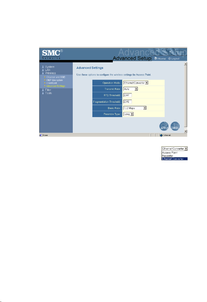
Advanced Settings
Operation Mode: This may be set to Access Point,
Repeater or Ethernet Converter.
These modes are described below:
• Access Point – functions as a standard IEEE 802.11b access
point
• Repeater – repeats an access point’s signals to extend the
acess points coverage
• Ethernet Converter – provides a wireless connection to an
access point via an RJ-45 connection to devices such as
Microsoft Xbox and Ethernet ready embedded devices
19
Page 2

S
YSTEM CONFIGURATION
The parameters that follow may be configured in any of the three
modes descibed above but the user is advised to leave them at
their default settings.
Transmission Rate: Set the data rate transmitted from
the Wireless Access Point. The lower the data rate,
the longer the transmission distance.
(Default: Fully Automatic.)
RTS Threshold: Set the RTS (Request to Send) frame length. You
may configure the access point to initiate an RTS frame. If the
packet size is smaller than the preset RTS threshold size, the
RTS/CTS mechanism will NOT be enabled
The access point sends Request to Send (RTS) frames to a
particular receiving station to negotiate the sending of a data
frame. After receiving an RTS, the station sends a CTS (Clear to
Send) frame to acknowledge the right of the sending station to
send data frames. The access points contending for the medium
may not be aware of each other. The RTS/CTS mechanism can
solve this “Hidden Node Problem.” (Default: 2347)
Fragmentation Threshold: The Fragmentation Threshold can be
set between 256 and 2,346. If the packet size is smaller than the
preset Fragment size, the packet will not be segmented.
Fragmentation of the PDUs (Package Data Unit) can increase the
reliability of transmissions because it increases the probability of
a successful transmission due to smaller frame size. If there is
significant interference present, or collisions due to high network
utilization, try setting the fragment size to send smaller fragments.
This will enable the retransmission of smaller frames much faster.
However, it is more efficient to set the fragment size larger if very
little or no interference is present because it requires overhead to
send multiple frames. (Default: 2346)
20
Page 3

N
AVIGATING THE WEB BROWSER INTERFACE
Basic Rate: The highest rate specified is the rate the
Wireless Access Point will use when transmitting
broadcast/multicast and management frames.
(Default: 1, 2 Mbps.)
Preamble Type: The access points and client card drivers have a
radio setting for RF Preamble. Enabling it can boost your
throughput. Preamble Type offers a drop-down list with two
options: Long or Short. If you are not sure whether all the clients
and access point radios in your wireless network support the
Short RF preamble, then leave this setting on Long (default).
Transmit Power: Set the signal strength transmitted from
the access point. The longer the transmission distance,
the higher the transmission power required. (Default:
Super)
Selections - Weak, Medium, Normal, High and Super
21
Page 4

S
YSTEM CONFIGURATION
Filter
The MAC Filtering feature of the SMC2671W allows you to
control access to your network clients based on the MAC (Media
Access Control) Address of the client machine. This ID is unique
to each network adapter. If the MAC address is listed in the table,
that client machine will not have access to the network.
22
Page 5
N
AVIGATING THE WEB BROWSER INTERFACE
Tools
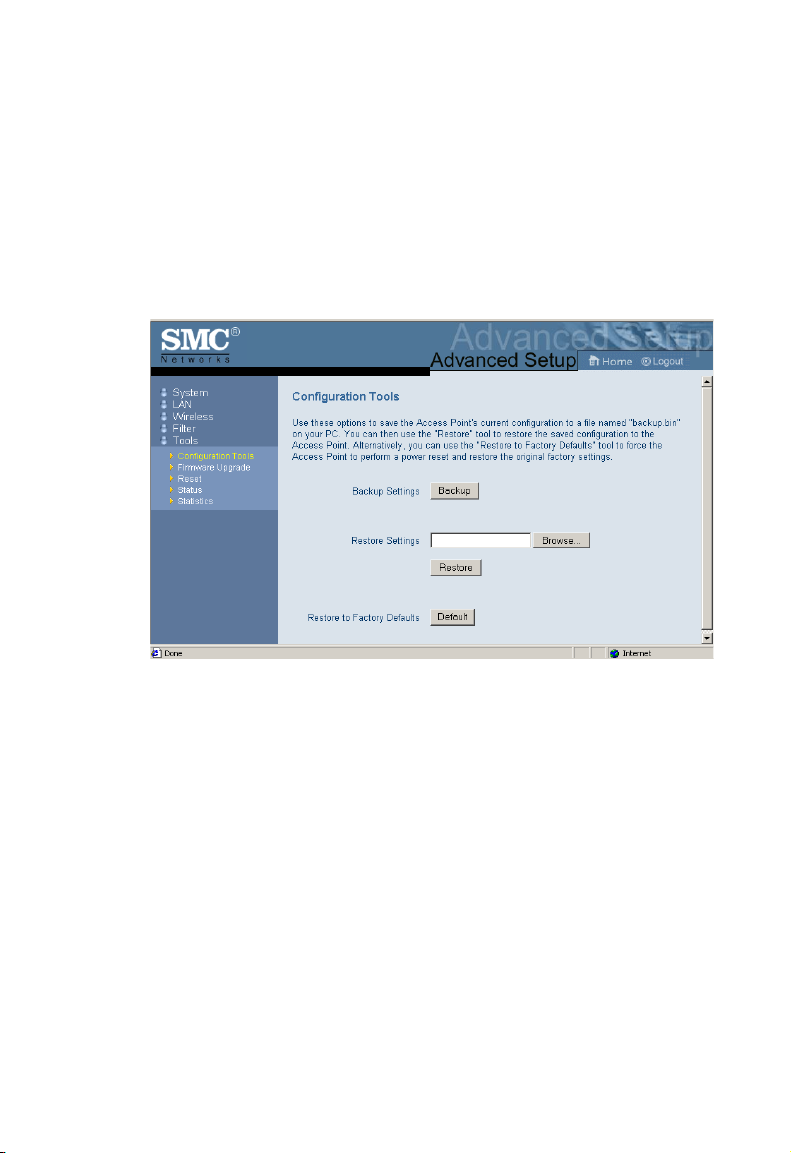
Use the Tools menu to backup the current configuration, restore a
previously saved configuration, restore factory settings, update
firmware, and reset the SMC2671W.
Configuration Tools
• Backup Settings – saves the SMC2671W’s configuration to a
file.
• Restore Settings – restores settings from a saved backup
configuration file.
• Restore to Factory Defaults – restores the SMC2671W
settings back to the factory default original.
23
Page 6
S
YSTEM CONFIGURATION
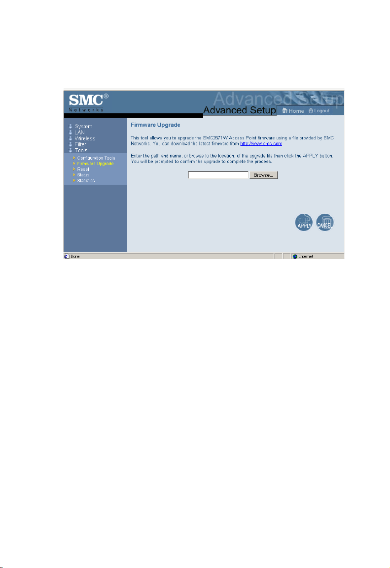
Firmware Upgrade
Use this screen to update the firmware or user interface to the
latest versions. Download the upgrade file from the web site and
save it to your hard drive. In the Upgrade Target field, choose
Firmware. Then click Browse to look for the previously
downloaded file. Click APPLY. Check the Status page Information
section to confirm that the upgrade process was successful.
24
Page 7
N
AVIGATING THE WEB BROWSER INTERFACE
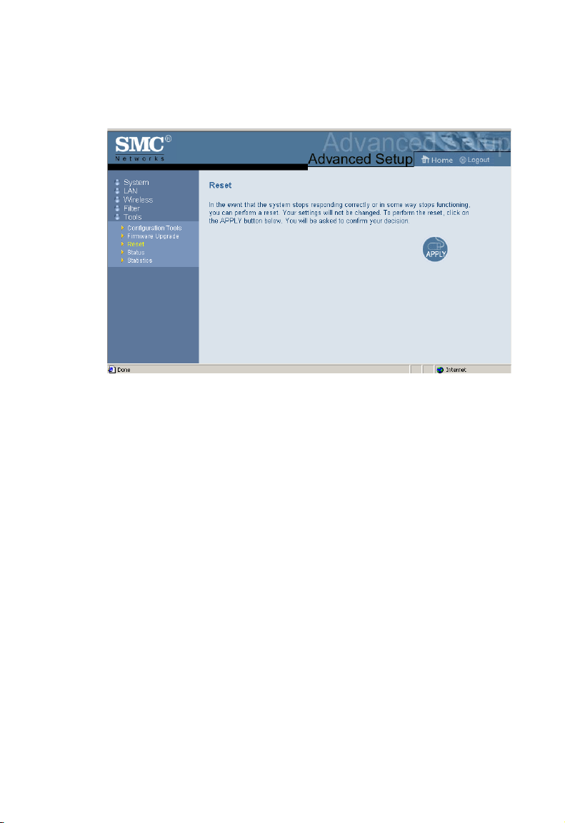
Reset
Click APPLY to reset the SMC2617W. The reset will be complete
when the power LED stops blinking.
25
Page 8

S
YSTEM CONFIGURATION
Status
The Status screen displays WAN/LAN connection status,
firmware, and hardware version numbers of the SMC2671W.
Statistics
The Statistics page displays transmit and receive statistics for all
associated stations.
26
Page 9
U
TILITY INSTALLATION
(98/ME/NT/2000)
Utility Installation (98/Me/NT/2000)
1. Insert the SMC2671W utility disk into the floppy drive on your
PC, and then enter the following command: A:\setup. Follow
the on-screen instructions to install the utility program.
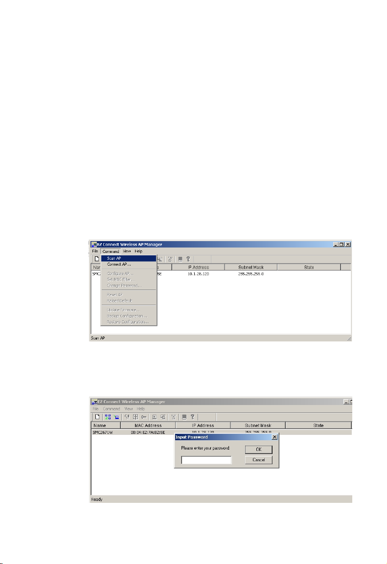
Using the AP Management Utility
1. Click Start/Programs/SMC/EZ Connect Wireless AP
Manager. The program will automatically scan for all access
points on the network. If you want to subsequently detect all
access points on the network, click Command and then select
Scan AP from the menu.
2. From the list of detected SMC2671Ws, double-click on the
unit you wish to configure. A dialogue box will prompt you for
the login password.
27
Page 10

S
YSTEM CONFIGURATION
3. Enter the default password: Private.
4. Click the Command main menu item.
5. Select Configure AP In the Command main menu.
Configure AP
The Configure AP screen displays the AP status and settings.
The screen is divided into two sections. The first section is
read-only.
BSS ID – Media Access Control address.
Regulation Domain - Countries have different regulations
regarding the use of radio frequencies.
WEP – WEP (Wired Equivalent Privacy) Enabled/Disabled status.
Associated Stations – Number of wireless clients.
28
Page 11

U
TILITY INSTALLATION
Firmware Version – Current firmware version.
SSID – Clients in your network must use the same value entered
here. (Default: WLAN)
Channel – Set the operating radio channel number. (Default: 11)
Note: Available channel settings are limited by local regulations
which determine which channels are available. (FCC/IC:
1-11, ETSI: 1-13, France: 10-13, Spain: 10-11, MKK: 1-14)
RTS Threshold – Set the RTS Threshold to enable the RTS/CTS
mechanism. (Default: 2,346 which means Disabled)
Accept ANY SSID – Checking this box enables the access point
to accept the association of wireless clients using ANY as their
SSID. If this feature is disabled (the box is not checked), the
wireless clients must use the same SSID as the access point.
(thus enhancing security)
IP Address – Set the IP address as required.
(Default: 192.168.2.254)
(98/ME/NT/2000)
Subnet Mask – Set the Subnet Mask as required.
(Default: 255.255.255.0)
Default Gateway – Set the default gateway as required.
(Default: 0.0.0.0)
29
Page 12

S
YSTEM CONFIGURATION
DHCP Client – You can enable the DHCP Client function to
automatically get an IP Address, Subnet Mask, and Default
Gateway from a DHCP server in your network. (Default: Enabled)
Encryption – Click the Security
button to setup WEP security.
WEP – Wired Equivalent Privacy
(WEP) is implemented in this device
to prevent unauthorized access to
your wireless network and provide
more secure data transmissions. The
higher the number of bits in the
encryption key, the higher the level of
security. All clients in the wireless
network must have the same WEP
setting. (Default: Disabled)
Create with Passphrase – The security key for WEP encryption
is generated from your Passphrase string, so it must be the same
on all clients in your network.
Manual Entry – Allows manual entry of security keys.
(2 Hexadecimal digits in each block: A~F & 0~9)
30
Page 13

U
TILITY INSTALLATION
Key 1~4 – Each 64-bit Key ID contains 10 HEX digits but 128-Bit
encryption has only 1 Key which contains 26 HEX digits. All
wireless devices must have the same Key ID element values to
communicate
Default Key ID – Choose the Key ID that has the encryption
string you prefer. If using a key generated from a Passphrase, you
must use the same Passphrase and key on each station.
(98/ME/NT/2000)
Operation Mode
Click the Advance ... button to set the operation
mode.
The Mode can be set to:
• Access Point – functions as a standard
IEEE 802.11b access point
• Repeater – repeats an access point’s signals to extend the
acess points coverage
• Ethernet Converter – provides a wireless connection to an
access point via an RJ-45 connection to devices such as
Microsoft Xbox
– provides a wireless connection to an access point or
wireless adapter via an RJ-45 connection to Ethernet ready
embedded devices
31
Page 14

S
YSTEM CONFIGURATION
Set MAC Filter
In the Set MAC Filter screen, you can decide which wireless
devices are allowed to connect to the access point by adding the
MAC address of allowed clients. Wireless devices that are not in
the table will be denied access.
Filtering – Choose Enabled to
enable the MAC Filter
(Default: Disabled).
Key in the MAC addresses of
Ethernet devices you wish to
allow to associate with the AP.
Note: The format is 12 Hexadecimal digits. e.g. 0090D112AF89
Click Add and then click Save to
save the changes.
Otherwise, click Add from File..
to add a previously saved text
file of MAC addresses and click
Save to save the changes.
Notes: 1. The table allows you to enter a maximum of 64 MAC
addresses.
2. This table will be blank if the SMC2671W is set the
Ethernet Converter mode since the Ethernet converter
has no clients but is itself the client of an associated
access point.
32
Page 15

U
TILITY INSTALLATION
(98/ME/NT/2000)
Change Password
A password is required to configure
the SMC2671W. Changing the
password from the default value to
a value of your choice will improve
network security. On the Change
Password screen you may change the password on the access
point.
Reset AP
The Reset AP screen will let you reboot the
SMC2671W.
Reload Default
The Reload Default screen will let you reload
the factory default settings.
Updating Firmware
Click on the Browse button in the
Firmware Update screen to update
firmware.
33
Page 16

S
YSTEM CONFIGURATION
Saving Configuration Settings
Select Backup Configuration
... in the main Command
Menu to save the current
configuration settings.
Restoring Configuration Settings
Select Restore Configuration
in the Main Command Menu
to restore a previous
configuration.
34
Page 17

N
ETWORK
The Wireless Solution supports a stand-alone wireless network
configuration, as well as an integrated configuration with 10 Mbps
Ethernet LANs. For a list of the maximum distances between the
AP/Bridge and wireless clients, refer to page 40.
The wireless network cards and adapters can be configured as:
• Ad hoc – for small departmental or SOHO LANs
• Infrastructure – for enterprise LANs
C
ONFIGURATION
P
AND
LANNING
Network Topologies
Ad Hoc Wireless LAN
An ad hoc wireless LAN
consists of a group of
computers, each equipped
with a wireless adapter or
Ethernet converter,
connected via radio
signals as an independent
wireless LAN. Computers
in a specific ad hoc
wireless LAN must be
configured to the same
radio channel.
SMC2671 in Ethernet
Converter Mode
Ad Hoc Wireless LAN
Notebook with
Wireless USB Adapter
Notebook with
Wireless PC Card
An ad hoc wireless LAN can be used for a small branch office or
SOHO operation.
35
Page 18

N
ETWORK CONFIGURATION AND PLANNING
Infrastructure Wireless LAN
An integrated wired and wireless LAN is called an Infrastructure
configuration. A Basic Service Set (BSS) consists of a group of
wireless PC users, and an access point that is directly connected
to the wired LAN. Each wireless PC in this BSS can talk to any
computer in its wireless group via a radio link, or access other
computers or network resources in the wired LAN infrastructure
via the access point.
The infrastructure configuration permits wireless clients to access
the wired LAN and also increases the effective wireless
transmission range for wireless clients as their signal can be
passed through multiple access points.
A wireless infrastructure can be used for access to a central
database, or for connection between mobile workers, as shown in
the following figure.
Wired LAN Extension
to Wireless Adapters
File
Server
Desktop PC
Switch
Notebook with Wireless
PC Card Adapter
36
PC with Wireless
PCI Adapter
SMC2671W in
Access Point Mode
Page 19

N
ETWORK TOPOLOGIES
Infrastructure Wireless LAN for Roaming Wireless PCs
The Basic Service Set (BSS) is the communications domain for
each wireless access point. For wireless PCs that do not need to
support roaming, set the domain identifier (SSID) of the wireless
card to the SS ID of the access point to which you want to
connect. Check with your administrator for the SS ID of the
access point to which he wants you to connect.
A wireless infrastructure can also support roaming for mobile
workers. More than one access point can be configured to create
an Extended Service Set (ESS). By placing the Access Points so
that a continuous coverage area is created, wireless users within
this ESS can roam freely. All wireless network cards, adapters,
and the wireles access point within a specific ESS must be
configured with the same SSID.
Note: If Access Point 2 is replaces by an SMC2671W set to
Repeater mode then the SMC2761W will not establish its
own BSS, but will repeat data messeges between Acess
Point 1 and end users, thus extending the coverage area
of Access Point 1.
Desktop PC
Switch
PC with Wireless
PCI Adapter
Access Point 1
File
Server
Notebook with Wireless
PC Card Adapter
<BSS1>
Switch
Access Point 2
<ESS>
Seamless Roaming
Notebook with Wireless
PC Card Adapter
<BSS2>
37
Page 20

N
ETWORK CONFIGURATION AND PLANNING
A Wireless LAN with Internet Access
In this application one SMC2617W is in Ethernet Converter mode
connected to a Microsoft Xbox. Another SMC2617W is acting in
Access Point mode. This provides a wireless network and also
Intrnernet access for applications including Internet game
playing.
Wired LAN Extension
to Wireless Adapters
Internet
Internet
Access
Device
SMC2671W in Ethernet
Converter mode
Notebook with Wireless
PC Card Adapter
SMC2671W in
Access Point mode
PC with wireless
PCI Adapter
38
Page 21

T
ROUBLESHOOTING
Check the following items before you contact Technical Support.
1. If mobile users do not have roaming access to the
SMC2671W:
Make sure that all the SMC2671Ws and stations in the ESS
in which the WLAN mobile users can roam are configured to
the same WEP setting, SSID, and authentication algorithm.
2. If the management utility cannot connect to the SMC:
Check that your local IP address settings conform to the
SMC2671W settings.
3. If you forgot your password or your SMC2671W has locked
up, you can reset it to factory defaults by performing the
following steps:
• Start the utility program.
• On the main menu, click Command. Click Reload Default.
or
• Power off the SMC2671W.
• Use a pin to push in the reset button located on the bottom
of the SMC2671W (marked Reload. )
• While holding in the button, apply power to the AP.
• The AP will begin to load the default settings.
• Wait for about 5 seconds. Release the button.
• The AP will restart with the factory default settings.
39
Page 22

T
ROUBLESHOOTING
802.11b Wireless Products Maximum
Distance Table
Important Notice
Maximum distances posted below are actual tested distance
thresholds. However, there are many variables such as barrier
composition and construction, and local environmental
interference that may impact your actual distances and cause you
to experience distance thresholds far lower than those we post
below.
IEEE 802.11b Wireless Products Maximum Distance Table
Speed and Distance Ranges
Environmental Condition 11 Mbps 5.5 Mbps 2 Mbps 1 Mbps
Open Environment: A
line-of-sight environment
with no interference or
obstruction between AP/
Bridge and users.
Semi-Open
Environment: An
environment with no
major obstructions such
as walls or privacy
cubicles between the AP
and users.
Closed Environment: A
typical office or home
environment with floor to
ceiling obstructions
between the AP and
users.
180 m
(590 ft)
50 m
(165 ft)
25 m
(80 ft)
300 m
(985 ft)
70 m
(230 ft)
35 m
(115 ft)
450 m
(1475 ft)
90 m
(295 ft)
45 m
(150 ft)
550 m
(1805 ft)
120 m
(395 ft)
55 m
(180 ft)
40
Page 23

S
PECIFICATIONS
Maximum Channels
USA & Canada: 11, Europe (ETSI): 13, Japan: 14
Maximum Clients
64
Operating Range
Maximum distance at 11 Mbps: 180 m (591 ft)
Maximum distance at 5.5 Mbps: 300 m (984 ft)
Maximum distance at 2 Mbps: 450 m (1476 ft)
Maximum distance at 1 Mbps: 550 m (1804 ft)
Cell Separation (for roaming clients)
60 m (197 ft) between access points
Data Rate
1, 2, 5.5, 11 Mbps per channel
Network Configuration
LAN to access point to wireless card
Access point to wireless card
Operating Frequency
USA, Canada: 2.400-2.4835 GHz
Europe (ETSI): 2.400-2.4835 GHz
Japan: 2.400-2.497 GHz
Sensitivity
1, 2, 5.5 Mbps: -82 dBm
11 Mbps: -78 dBm typical
Modulation
CCK, BPSK, QPSK
Power Supply
Input: 100-240 AC, 50-60 Hz
Output: 9 VDC, 1A
Output Power
> +15dBm minimum
Physical Size
13.74 x 10.8 x 3.01 cm (5.41 x 4.25 x 1.19 in)
41
Page 24

S
PECIFICATIONS
Weight
210 g (7.4 oz)
LED Indicators
Power, Ethernet Link/Activity,
Wireless Activity
Network Management
Windows 98/Me/NT/2000 SNMP Management Utility
Operating System Compatibility
Windows 98/Me/NT/2000
Encryption
64-bit/128-bit WEP
Temperature
Operating: 0 to 50 °C (32 to 122 °F)
Storage: 0 to 70
°C (32 to 158 °F)
Humidity
5% to 85% (non-condensing)
Compliances
CE Mark
EN55022 Class B
EN55024
IEC 61000-42/3/4/6/11
Emissions
FCC Class B
ETS 300 328
RCR STD-33A
Safety
CSA/NTRL (CSA 22.2 No. 950 & UL 1950)
EN60950 (TüV/GS)
Vibration/Shock/Drop
IEC 68-2-34/IEC 68-2-32
Standards
IEEE 802.3x 10BASE-T/100BASE-TX (RJ-45)
IEEE 802.11b
42
Page 25

T
ERMINOLOGY
The following is a list of terminology that is used in this document.
Access Point – An internetworking device that seamlessly
connects wired and wireless networks.
Ad Hoc – An ad hoc wireless LAN is a group of computers each
with LAN adapters, connected as an independent wireless LAN.
Backbone – The core infrastructure of a network. The portion of
the network that transports information from one central location
to another central location where it is unloaded onto a local
system.
Base Station – In mobile telecommunications, a base station is
the central radio transmitter/receiver that maintains
communications with the mobile radio telephone sets within its
range. In cellular and personal communications applications,
each cell or micro-cell has its own base station; each base station
in turn is interconnected with other cells’ bases.
BSS – BSS stands for “Basic Service Set.” It is an Access Point
and all the LAN PCs that are associated with it.
CSMA/CA – Carrier Sense Multiple Access with Collision
Avoidance.
ESS – ESS (ESS-ID, SSID) stands for “Extended Service Set.”
More than one BSS is configured to become an Extended
Service Set. LAN mobile users can roam between different BSSs
in an ESS (ESS-ID, SSID).
43
Page 26

T
ERMINOLOGY
Ethernet – A popular local area data communications network,
which accepts transmission from computers and terminals.
Ethernet operates on a 10 Mbps baseband transmission rate,
using a shielded coaxial cable or shielded twisted pair telephone
wire.
Infrastructure – An integrated wireless and wired LAN is called
an Infrastructure configuration.
Fragmentation Threshold – In the 802.11 Standard, the MAC
Layer may fragment and reassemble directed MSDUs or
MMPDUs. The fragmentation and defragmentation mechanisms
allow for fragment re-transmission.
Preamble Type – Some access points and client card drivers
have a radio setting for “Short” RF Preamble. If all the clients and
access points in your wireless network have this feature, then
enabling it can boost your throughput. However, if a radio does
not support this feature, then it will not be able to communicate
with any other radios that have this set to “Short.”
Roaming – A wireless LAN mobile user moves around an ESS
and maintains a continuous connection to the Infrastructure
network.
RTS Threshold – Transmitters contending for the medium may
not be aware of each other. RTS/CTS mechanism can solve this
“Hidden Node Problem.” If the packet size is smaller than the
preset RTS Threshold size, the RTS/CTS mechanism will NOT be
enabled.
WEP – “Wired Equivalent Privacy” is based on the use of 64-bit or
128-bit keys and the popular RC4 encryption algorithm. Wireless
devices without a valid WEP key will be excluded from network
traffic.
44
Page 27

Page 28

FOR TECHNICAL SUPPORT, CALL:
From U.S.A. and Canada (24 hours a day, 7 days a week)
(800) SMC-4-YOU; (949) 679-8000; Fax: (949) 679-1481
From Europe (8:00 AM - 5:30 PM UK Time)
44 (0) 118 974 8700; Fax: 44 (0) 118 974 8701
INTERNET
E-mail addresses:
techsupport@smc.com
european.techsupport@smc-europe.com
support@smc-asia.com
Driver updates:
http://www.smc.com/index.cfm?action=tech_support_drivers_downloads
World Wide Web :
http://www.smc.com
http://www.smc-europe.com
http://www.smc-asia.com
FOR LITERATURE OR ADVERTISING RESPONSE, CALL:
U.S.A. and Canada: (800) SMC-4-YOU; Fax (949) 679-1481
Spain: 34-93-477-4935; Fax 34-93-477-3774
UK: 44 (0) 1932 866553; Fax 44 (0) 118 974 8701
France: 33 (0) 41 38 32 32; Fax 33 (0) 41 38 01 58
Italy: 39 (0) 335 5708602; Fax 39 02 739 14 17
Benelux: 31 33 455 72 88; Fax 31 33 455 73 30
Central Europe: 49 (0) 89 92861-0; Fax 49 (0) 89 92861-230
Nordic: 46 (0) 868 70700; Fax 46 (0) 887 62 62
Eastern Europe: 34 -93-477-4920; Fax 34 93 477 3774
Sub Saharian Africa: 27 0126610232; Fax 27-11 314 9133
North West Africa: 216 71236616; Fax 216 71751415
CIS: 7 (095) 789 35 73; Fax 7 (095) 789 35 73
PRC (Beijing): 86-10-8251-1550; Fax 86-10-8251-1551
PRC (Shanghai): 86-21-6485-9922; Fax 86-21-6495-7924
Taiwan: 886-2-8797-8006; Fax 886-2-8797-6288
Asia Pacific: (65) 6 238 6556; Fax (65) 6 238 6466
Korea: 82-2-553-0860; Fax 82-2-553-7202
Japan: 81-3-5645-5715; Fax 81-3-5645-5716
Australia: 61-2-8875-7887; Fax 61-2-8875-7777
India: 91 22 5696 2790; Fax 91 22 5696 2794
Middle East: 97 14 299 4466 Fax 97 14 299 4664
Thailand: 66 2 651 8733 Fax 66 2 651 8737
If you are looking for further contact information, please visit www.smc.com,
www.smc-europe.com, or www.smc-asia.com.
38 Tesla
Irvine, CA 92618
Phone: (949) 679-8000
Model Number: SMC2671W
Revision Number E062003-R01 F 1.0
 Loading...