

Page 1

ES4626/ES4650
Layer 3 Gigabit Switch
Management Guide
1
www.edge-core.com
Page 2

Preface
ES4626/ES4650 is a routing switch that can be deployed as the core layer device for campus and
enterprise networks, or as an aggregation device for IP metropolitan area networks (MAN). The
ES4626 provides 24 fixed 1000MB port (4 of which are fixed 1000MB Combo fiber cable
port/copper cable ports) and 2 10GB XFP ports. The ES4650 provides 48 fixed 1000MB port (4 of
which are fixed 1000MB Combo fiber cable port/copper cable ports) and 2 10GB XFP ports.
ES4626/ES4650 can seamlessly support various network interfaces from 100Mb, 1000Mb to
10Gb Ethernets.
We are providing this manual for your better understanding, usage and maintenance of the
ES4626/ES4650. We strongly recommend you to read through this manual carefully before the
installation and configuration to avoid possible damage and malfunction to the switch. Thank you
for your choice and purchase of this networking product from Accton Technology Corp. We
sincerely hope our products and services satisfy you.
2
Page 3

Contents
Preface 2
Contents 3
Chapter 1 Switch Management _________________________________________ 12
1.1 Management Options ____________________________________________ 12
1.1.1 Out-of-band Management____________________________________________ 12
1.1.2 In-band Management________________________________________________ 15
1.2 Management Interface____________________________________________ 21
1.2.1 CLI Interface ______________________________________________________ 21
1.2.2 WEB Interface _____________________________________________________ 28
Chapter 2 Basic Switch Configuration ____________________________________ 30
2.1 Basic Switch Configuration Commands ___________________________ 30
2.1.1 calendar set ________________________________________________________ 30
2.1.2 config _____________________________________________________________ 30
2.1.3 enable_____________________________________________________________ 31
2.1.4 disable ____________________________________________________________ 31
2.1.5 enable password ____________________________________________________ 31
2.1.6 exec timeout________________________________________________________ 32
2.1.7 exit _______________________________________________________________ 33
2.1.8 help_______________________________________________________________ 33
2.1.9 ip host ____________________________________________________________ 33
2.1.10 hostname __________________________________________________________ 34
2.1.11 uername password __________________________________________________ 34
2.1.12 uername nopassword ________________________________________________ 35
2.1.13 username access-level________________________________________________ 35
2.1.14 reload_____________________________________________________________ 35
2.1.15 set default _________________________________________________________ 36
2.1.16 setup______________________________________________________________ 36
2.1.17 language___________________________________________________________ 36
2.1.18 write______________________________________________________________ 36
2.2 Maintenance and Debug Commands ______________________________ 37
2.2.1 ping ______________________________________________________________ 37
2.2.2 Telnet_____________________________________________________________ 38
2.2.3 SSH ______________________________________________________________ 41
3
Page 4

2.2.4 traceroute _________________________________________________________ 46
2.2.5 show______________________________________________________________ 47
2.2.6 debug _____________________________________________________________ 53
2.3 Configuring Switch IP Addresses _________________________________ 53
2.3.1 Configuring Switch IP Addresses Task Sequence _________________________ 53
2.3.2 Commands for Configuring Switch IP Addresses _________________________ 54
2.4 SNMP___________________________________________________________ 56
2.4.1 Introduction to SNMP _______________________________________________ 56
2.4.2 Introduction to MIB_________________________________________________ 57
2.4.3 Introduction to RMON ______________________________________________ 58
2.4.4 SNMP C onfiguration ________________________________________________ 59
2.4.5 Typical SNMP Configuration Examples_________________________________ 66
2.4.6 SNMP Tr oubl eshootin g Hel p__________________________________________ 67
2.5 Switch Upgrade__________________________________________________ 72
2.5.1 BootROM Upgrade _________________________________________________ 72
2.5.2 FTP/TFTP Upgrade _________________________________________________ 75
2.6 WEB Management _______________________________________________ 90
2.6.1 Switch Basic Configuration___________________________________________ 90
2.6.2 SNMP C onfiguration ________________________________________________ 91
2.6.3 Switch Upgrade_____________________________________________________ 93
2.6.4 Monitor and debug command _________________________________________ 95
2.6.5 Switch basic information _____________________________________________ 97
2.6.6 Switch on-off configuration ___________________________________________ 98
2.6.7 Switch maintenance _________________________________________________ 98
2.6.8 Telnet service configuration___________________________________________ 99
2.6.9 username service____________________________________________________ 99
2.6.10 Basic host configuration_____________________________________________ 100
Chapter 3 Port Configuration__________________________________________ 101
3.1 Introduction to Port _____________________________________________ 101
3.2 Port Configuration ______________________________________________ 101
3.2.1 Network Port Configuration _________________________________________ 101
3.2.2 VLAN Interface Configuration_______________________________________ 109
3.2.3 Port Mirroring Configuration_________________________________________112
3.3 Port Configuration Example _____________________________________ 114
3.4 Port Troubleshooting Help_______________________________________ 115
4
Page 5

3.4.1 Monitor and Debug Commands _______________________________________115
3.4.2 Port T roubleshooting Help____________________________________________116
3.5 WEB Management ______________________________________________ 116
3.5.1 Ethenet port configuration ___________________________________________116
3.5.2 Vlan interface configuration __________________________________________118
3.5.3 Port mirroring configuration_________________________________________ 120
3.5.4 Port debug and maintenance_________________________________________ 120
Chapter 4 MAC Table Configuration ____________________________________ 123
4.1 Introduction to MAC Table_______________________________________ 123
4.1.1 Obtaining MAC Table ______________________________________________ 123
4.1.2 Forward or Filter __________________________________________________ 125
4.2 MAC Table Configuration________________________________________ 126
4.2.1 mac-address-table aging-time ________________________________________ 126
4.2.2 mac-address-table static_____________________________________________ 126
4.2.3 mac-address-table discard___________________________________________ 127
4.3 Typical Configuration Examples _________________________________ 128
4.4 Troubleshooting Help ___________________________________________ 128
4.4.1 Monitor and Debug Comm ands ______________________________________ 128
4.4.2 Troubleshooting Help_______________________________________________ 129
4.5 MAC Address Function Extension________________________________ 129
4.5.1 MAC Address Binding______________________________________________ 129
4.6 WEB Management ______________________________________________ 137
4.6.1 MAC address table configuration_____________________________________ 137
4.6.2 MAC address table configuration_____________________________________ 140
Chapter 5 VLAN Configuration ________________________________________ 145
5.1 Introduction to VLAN____________________________________________ 145
5.2 VLAN Configuration_____________________________________________ 146
5.2.1 VLAN Configuration Task Sequence __________________________________ 146
5.2.2 VLAN Configuration Commands_____________________________________ 148
5.2.3 T ypic al VL AN Application___________________________________________ 152
5.3 GVRP Configuration ____________________________________________ 154
5.3.1 GVRP Con fig ura ti on Task Sequence __________________________________ 155
5.3.2 GVRP C ommands _________________________________________________ 156
5.3.3 Typical GVRP Application___________________________________________ 158
5
Page 6

5.4 VLAN Troubleshooting Help _____________________________________ 160
5.4.1 Monitor and Debug Information______________________________________ 160
5.4.2 VLAN Troubleshooting Help_________________________________________ 162
5.5 WEB Management ______________________________________________ 162
5.5.1 Vlan configuration _________________________________________________ 162
5.5.2 GVRP configuration________________________________________________ 168
5.5.3 VLAN debug and maintenance_______________________________________ 169
Chapter 6 MSTP Configuration ________________________________________ 171
6.1 MSTP Introduction______________________________________________ 171
6.1.1 MSTP Region _____________________________________________________ 171
6.1.2 Port Roles ________________________________________________________ 173
6.1.3 MSTP Load Balance________________________________________________ 173
6.2 Configuring MSTP ______________________________________________ 173
6.2.1 MSTP Configuration Task Sequence __________________________________ 173
6.2.2 MSTP Configuration Command______________________________________ 176
6.3 MSTP Example _________________________________________________ 184
6.4 MSTP Troubleshooting __________________________________________ 189
6.4.1 Monitoring And Debugging Command ________________________________ 189
6.4.2 MSTP Troubleshooting Help_________________________________________ 193
Chapter 7 IGMP Snooping Configuration ________________________________ 194
7.1 Introduction to IGMP Snooping __________________________________ 194
7.2 IGMP Snooping Configuration ___________________________________ 194
7.2.1 IGMP Snooping Configuration Task __________________________________ 194
7.2.2 IGMP Snooping Configuration Command______________________________ 196
7.3 IGMP Snooping Example ________________________________________ 199
7.4 IGMP Snooping Troubleshooting Help____________________________ 202
7.4.1 Monitor and Debug Comm ands ______________________________________ 202
7.4.2 IGMP Snooping Troubleshooting Help_________________________________ 206
7.5 Web Management_______________________________________________ 206
7.5.1 Enable IGMP Snooping on the switch _________________________________ 206
7.5.2 IGMP Snooping Configuration_______________________________________ 206
7.5.3 IGMP Snooping static multicast configuration __________________________ 208
Chapter 8 802.1X CONFIGURATION ___________________________________ 210
8.1 802.1X Introduction _____________________________________________ 210
6
Page 7

8.2 802.1X Configuration____________________________________________ 211
8.2.1 802.1X Configuration Task Sequence___________________________________211
8.2.2 802.1X Configuration Comm and _____________________________________ 216
8.3 802.1X Apply Example___________________________________________ 226
8.4 802.1X Trouble Shooting ________________________________________ 227
8.4.1 802.1X Debug and Monitor Command_________________________________ 227
8.4.2 802.1X Troubleshooting _____________________________________________ 232
8.5 WEB Management ______________________________________________ 233
8.5.1 RADIUS client configuration ________________________________________ 233
8.5.2 802.1X Configuration_______________________________________________ 235
Chapter 9 ACL Configuration__________________________________________ 239
9.1 Introduction to ACL _____________________________________________ 239
9.1.1 Access list_________________________________________________________ 239
9.1.2 Access-group______________________________________________________ 239
9.1.3 Access list Action and Global Default Action____________________________ 240
9.2 ACL configuration ______________________________________________ 240
9.2.1 ACL Configuration Task Sequence____________________________________ 240
9.2.2 ACL Configuration Commands ______________________________________ 244
9.3 ACL Example___________________________________________________ 249
9.4 ACL Troubleshooting Help_______________________________________ 250
9.4.1 ACL Debug and Monitor Commands__________________________________ 250
9.4.2 ACL Troubleshooting Help __________________________________________ 252
9.5 Web Management_______________________________________________ 252
9.5.1 Add standard numeric IP ACL configuration ___________________________ 253
9.5.2 Delete standard numeric IP ACL configuration _________________________ 253
9.5.3 Extended numeric ACL configuration _________________________________ 253
9.5.4 Standard ACL name configuration____________________________________ 255
9.5.5 Extended ACL name configuration____________________________________ 256
9.5.6 Firewall configuration ______________________________________________ 256
9.5.7 ACL port binding configuration ______________________________________ 257
Chapter 10 Port Channel Configuration __________________________________ 258
10.1 Introduction to Port Channel___________________________________ 258
10.2 Port Channel Configuration____________________________________ 259
10.2.1 Port Channel Configuration Task Sequence ____________________________ 259
10.2.2 Port Channel Configuration Commands _______________________________ 260
7
Page 8

10.3 Port Channel Example_________________________________________ 262
10.4 Port Channel Troubleshooting Help ____________________________ 264
10.4.1 Monitor and Debug Commands ______________________________________ 264
10.4.2 Port Channel Troubleshooting Help ___________________________________ 269
10.5 Web Management_____________________________________________ 270
10.5.1 LACP port group configuration ______________________________________ 270
10.5.2 LACP port configuration____________________________________________ 271
Chapter 11 DHCP Configuration ________________________________________ 272
11.1 Introduction to DHCP ___________________________________________ 272
11.2 DHCP Server Configuration______________________________________ 273
11.2.1 DHCP Sever Configuration Task Sequence _____________________________ 273
11.2.2 DHCP Server Configuration Commands_______________________________ 275
11.3 DHCP Relay Configuration_______________________________________ 284
11.3.1 DHCP Relay Configuration Task Sequence_____________________________ 285
11.3.2 DHCP Relay Configuration Comm and ________________________________ 285
11.4 DHCP Configuration Example____________________________________ 287
11.5 DHCP Troubleshooting Help_____________________________________ 289
11.5.1 Monitor and Debug Commands ______________________________________ 289
11.5.2 DHCP T r oublesho oting Hel p_________________________________________ 294
11.6 WEB Management ______________________________________________ 294
11.6.1 DHCP server configuration__________________________________________ 294
11.6.2 DHCP relay configuration ___________________________________________ 301
11.6.3 DHCP debugging __________________________________________________ 302
Chapter 12 SNTP Configuration ________________________________________ 304
12.1 SNTP Configuration Commands _______________________________ 304
12.1.1 sntp server________________________________________________________ 304
12.1.2 sntp poll__________________________________________________________ 304
12.1.3 clock timezone_____________________________________________________ 305
12.2 Typical SNTP Configuration Examples__________________________ 306
12.3 SNTP Troubleshooting Help ___________________________________ 306
12.3.1 Monitor and Debug Commands ______________________________________ 306
12.4 WEB Management ____________________________________________ 307
12.4.1 SNTP/NTP server configuration_________________________________________ 307
12.4.2 Request interval configuration __________________________________________ 307
8
Page 9

12.4.3 Time difference _______________________________________________________ 308
12.4.4 Show sntp ___________________________________________________________ 308
Chapter 13 QoS Configuration _________________________________________ 309
13.1 QoS__________________________________________________________ 309
13.1.1 Introduction to QoS ________________________________________________ 309
13.1.2 QoS Configuration __________________________________________________311
13.1.3 QoS Example______________________________________________________ 325
13.1.4 QoS Tr oubles hootin g Hel p___________________________________________ 327
13.1.5 Web Management__________________________________________________ 333
13.2 PBR__________________________________________________________ 345
13.2.1 PBR Introduction__________________________________________________ 345
13.2.2 PBR Configuration_________________________________________________ 345
13.2.3 PBR Example _____________________________________________________ 349
Chapter 14 L3 Forward Configuration ____________________________________ 351
14.1 Layer3 Interface ______________________________________________ 351
14.1.1 Introduction to Layer3 Interface _____________________________________ 351
14.1.2 Layer3 interface configuration _______________________________________ 352
14.2 IP Forwarding ________________________________________________ 353
14.2.1 Introduction to IP Forwarding _______________________________________ 353
14.2.2 IP Route Aggregation Configuration __________________________________ 353
14.2.3 IP Forwarding Troubleshooting Help__________________________________ 354
14.3 ARP__________________________________________________________ 356
14.3.1 Introduction to ARP________________________________________________ 356
14.3.2 ARP configuration _________________________________________________ 357
14.3.3 ARP Forwarding Troubleshooting Help________________________________ 358
Chapter 15 Routing Protocol Configuration________________________________ 361
15.1 Route Table __________________________________________________ 361
15.2 Static Route __________________________________________________ 362
15.2.1 Introduction to Static Route _________________________________________ 362
15.2.2 Introduction to Default Route________________________________________ 363
15.2.3 Static Route Config uration __________________________________________ 363
15.2.4 Configuration Scenario _____________________________________________ 366
15.2.5 Tr oubleshooting Help_______________________________________________ 367
15.3 RIP __________________________________________________________ 367
15.3.1 Introduction to RIP ________________________________________________ 367
9
Page 10

15.3.2 RIP Configuration _________________________________________________ 369
15.3.3 Typical RIP Scenario _______________________________________________ 385
15.3.4 RIP Troubleshooting Help ___________________________________________ 387
15.4 OSPF ________________________________________________________ 389
15.4.1 Introduction to OSPF_______________________________________________ 389
15.4.2 OSPF Configuration________________________________________________ 392
15.4.3 Typical OSPF Scenario______________________________________________ 417
15.4.4 OSPF Troubleshooting Help _________________________________________ 424
15.5 Web Management_____________________________________________ 433
15.5.1 Static route _______________________________________________________ 433
15.5.2 RIP______________________________________________________________ 434
15.5.3 OSPF ____________________________________________________________ 438
Chapter 16 Multicast Protocol Configuration _______________________________ 447
16.1 Multicast Protocol Overview ___________________________________ 447
16.1.1 Introduction to Multicast____________________________________________ 447
16.1.2 Multicast Address__________________________________________________ 448
16.1.3 IP Multicast Packets Forwarding _____________________________________ 449
16.1.4 Application of Multicast_____________________________________________ 449
16.2 Common Multicast Configurations _____________________________ 450
16.2.1 Common Multicast Configuration Commands __________________________ 450
16.3 PIM-DM ______________________________________________________ 451
16.3.1 Introduction to PIM-DM____________________________________________ 451
16.3.2 PIM-DM Configuration_____________________________________________ 452
16.3.3 Typical PIM-DM Scenario___________________________________________ 454
16.3.4 PIM-DM Tr oublesho o ting Help ______________________________________ 455
16.4 PIM-SM_______________________________________________________ 459
16.4.1 Introduction to PIM-SM ____________________________________________ 459
16.4.2 PIM-SM Configuration _____________________________________________ 460
16.4.3 Typical PIM-SM Scenario ___________________________________________ 465
16.4.4 PIM-SM Troubleshooting Help_______________________________________ 467
16.5 DVMRP_______________________________________________________ 472
16.5.1 Introduction to DVMRP ____________________________________________ 472
16.5.2 DVMRP configuration ______________________________________________ 473
16.5.3 Typical DVMRP Scenario ___________________________________________ 480
16.5.4 DVMRP Troubleshooting Help _______________________________________ 480
10
Page 11

16.6 IGMP_________________________________________________________ 485
16.6.1 Introduction to IGMP ______________________________________________ 485
16.6.2 IGMP configuration ________________________________________________ 486
16.6.3 Typical IGMP Scenario _____________________________________________ 492
16.6.4 IGMP Troubleshooting Help _________________________________________ 492
16.7 web Management _____________________________________________ 495
16.7.1 Multicast common configuration _____________________________________ 495
16.7.2 PIM-DM configuration _____________________________________________ 496
16.7.3 PIM-SM configuration______________________________________________ 496
16.7.4 DVMRP configuration ______________________________________________ 498
16.7.5 IGMP configuration ________________________________________________ 500
16.7.6 Multicast inspect and debug _________________________________________ 501
Chapter 17 VRRP Configuration ________________________________________ 503
17.1 Introduction to VRRP__________________________________________ 503
17.2 VRRP Configuration___________________________________________ 504
17.2.1 VRRP Configuration Task Sequence __________________________________ 504
17.2.2 VRRP Configuration Commands _____________________________________ 505
17.2.3 Typical V RRP Application___________________________________________ 510
17.2.4 VRRP Troubleshooting Help__________________________________________511
Chapter 18 Cluster Network Management ________________________________ 514
18.1 Introduction to cluster network management____________________ 514
18.2 Basic Cluster Network Management Configuration ______________ 515
18.2.1 Cluster Network Management Configur ation Sequence __________________ 515
18.2.2 Cluster Configuration Commands ____________________________________ 517
11
Page 12

Chapter 1 Switch Management
1.1 Management Options
After purchasing the switch, the user needs to configure the switch for network
management. ES4626/ES4650 provides two management options: in-band management
and out-of-band management.
1.1.1 Out-of-band Management
Out-of-band management is the management through Console interface. Generally,
the user will use out-of-band management for the initial switch configuration, or when
in-band management is not available. For instance, the user must assign an IP address to
the switch via the Console interface to be able to access the switch through Telnet.
The procedures for managing the switch via Console interface are listed below:
Step 1: setting up the environment:
Connect with serial port
Fig 1-1 Out-of-band Management Configuration Environment
As shown in Fig 1-1, the serial port (RS-232) is connected to the switch with the serial
cable provided. The table below lists all the devices used in the connection.
Device Name Description
PC machine Has functional keyboard and RS-232, with terminal
emulator installed, such as HyperTerminal included in
Windows 9x/NT/2000/XP.
12
Page 13

Serial port cable One end attach to the RS-232 serial port, the other end to
the Console port.
ES4626/ES4650 Functional Console port required.
Step 2 Entering the HyperTerminal
Open the HyperTerminal included in Windows after the connection established. The
example below is based on the HyperTerminal included in Windows XP.
1) Click Start menu - All Programs – Accessories – Communication - HyperTerminal.
Fig 1-2 Opening HyperTerminal (1)
2) Type a name for opening HyperTerminal, such as “Switch”.
Fig 1-3 Opening HyperTerminal (2)
3) In the “Connecting with” drop-list, select the RS-232 serial port used by the PC, e.g.
COM1, and click “OK”.
13
Page 14
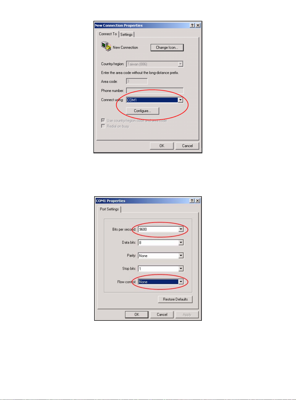
Fig 1-4 Opening HyperTerminal (3)
4) COM1 property appears, select “9600” for “Baud rate”, “8” for “Data bits”, “none” for
“Parity checksum”, “1” for stop bit and “none” for traffic control; or, you can also click
“Revert to default” and click “OK”.
Fig 1-5 Opening HyperTerminal (4)
Step 3 Entering switch CLI interface:
14
Page 15

Power on the switch. The following appears in the HyperTerminal windows, that is the
CLI configuration mode for ES4626.
ES4626 Management Switch
Copyright (c) 2001-2004 by Accton Technology Corporation.
All rights reserved.
Reset chassis ... done.
Testing RAM...
134,217,728 RAM OK.
Initializing...
Attaching to file system ... done.
Loading nos.img ... done.
Starting at 0x10000...
Current time is WED APR 20 09: 37: 52 2005
ES4626 Series Switch Operating System, Software Version ES4626 1.1.0.0,
Copyright (C) 2001-2006 by Accton Technology Corporation
http: //www.edge-core. com.
ES4626 Switch
26 Ethernet/IEEE 802.3 interface(s)
Press ENTER to start session
The user can now enter commands to manage the switch. For a detailed description for
the commands, please refer to the following chapters.
1.1.2 In-band Management
In-band management refers to the management by login to the switch using Telnet.
In-band management enables management of the switch for some devices attached to
15
Page 16

the switch. In the case when in-band management fails due to switch configuration
changes, out-of-band management can be used for configuring and managing the switch.
1.1.2.1 Management via Telnet
To manage the switch with Telnet, the following conditions should be met:
1) Switch has an IP address configured
2) The host IP address (Telnet client) and the switch’s VLAN interface IP address is
in the same network segment.
3) If not 2), Telnet client can connect to an IP address of the switch via other devices,
such as a router.
ES4626/ES4650 is a Layer 3 switch that can be configured with several IP addresses.
The following example assumes the shipment status of the switch where only VLAN1
exists in the system.
The following describes the steps for a Telnet client to connect to the switch’s VLAN1
interface by Telnet.
connect with serial
port cable
Fig 1-6 Manage the switch by Telnet
Step 1: Configure the IP addresses for the switch
First is the configuration of host IP address. This should be within the same network
segment as the switch VLAN1 interface IP address. Suppose the switch VLAN interface IP
address 10.1.128.251/24. Then, a possible host IP address is 10.1.128.252/24. Run “ping
10.1.128.251” from the host and verify the result, check for reasons if ping failed.
The IP address configuration commands for VLAN1 interface are listed below. Before
in-band management, the switch must be configured with an IP address by out-of-band
16
Page 17
management (i.e. Console mode), The configuration commands are as follows (All switch
configuration prompts are assumed to be “switch” hereafter if not otherwise specified):
Switch>
Switch>en
Switch#config
Switch(Config)#interface vlan 1
Switch(Config-If-Vlan1)#ip address 10.1.128.251 255.255.255.0
Switch(Config-If-Vlan1)#no shutdown
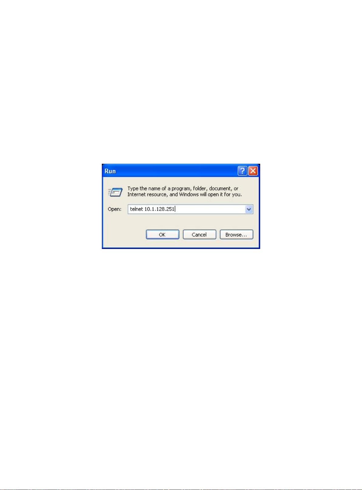
Step 2: Run Telnet Client program.
Run Telnet client program included in Windows with the specified Telnet target.
Fig 1-7 Run telnet client program included in Windows
Step 3: Login to the switch
Login to the Telnet configuration interface. Valid login name and password are required,
otherwise the switch will reject Telnet access. This is a method to protect the switch from
unauthorized access. As a result, when Telnet is enabled for configuring and managing
the switch, username and password for authorized Telnet users must be configured with
the following command:
telnet-user <user> password {0|7} <password>.
Assume an authorized user in the switch has a username of “test”, and password of “test”,
the configuration procedure should like the following:
Switch
>en
Switch#config
Switch(Config)#telnet-user test password 0 test
Enter valid login name and password in the Telnet configuration interface, Telnet user
17
Page 18

will be able to enter the switch’s CLI configuration interface. The commands used in the
Telnet CLI interface after login is the same as in that in the Console interface.
Fig 1-8 Telnet Configuration Interface
1.1.2.2 Management via HTTP
To manage the switch via HTTP, the following conditions should be met:
1) Switch has an IP address configured
2) The host IP address (HTTP client) and the switch’s VLAN interface IP address
are in the same network segment;
3) If 2) is not met, HTTP client should connect to an IP address of the switch via
other devices, such as a router.
Similar to management via Telnet, as soon as the host succeeds to ping an IP
address of the switch and to type the right login password, it can access the switch via
HTTP. The configuration sequence is as below:
Step 1: Configure the IP addresses for the switch and start the HTTP function on the
switch.
For configuring the IP address on the switch through out-of-band management, see
the relevant chapter.
To enable the WEB configuration, users should type the CLI command ip http server
in the global mode as below:
Switch
Switch#config
>en
18
Page 19

Switch(Config)#ip http server
Step 2: Run HTTP protocol on the host.
Open the Web browser on the host and type the IP address of the switch. Or run
directly the HTTP protocol on the Windows. For example, the IP address of the switch is
“10.1.128.251”.
Fig 1-9 Run HTTP Protocol
Step 3: Logon to the switch
To logon to the HTTP configuration interface, valid login user name and password are
required; otherwise the switch will reject HTTP access. This is a method to protect the
switch from the unauthorized access. Consequently, in order to configure the switch via
HTTP, username and password for authorized HTTP users must be configured with the
following command in the global mode:
username <username> password <show_flag> <password>. Suppose an
authorized user in the switch has a username as “test”, and password as “test”. The
configuration procedure is as below:
Switch
>en
Switch#config
Switch(Config)# username test password 0 test
The Web login interface is as below:
19
Page 20

Fig 1-10 Web Login Interface
Input the right username and password, and then the main Web configuration
interface is shown as below.
20
Page 21
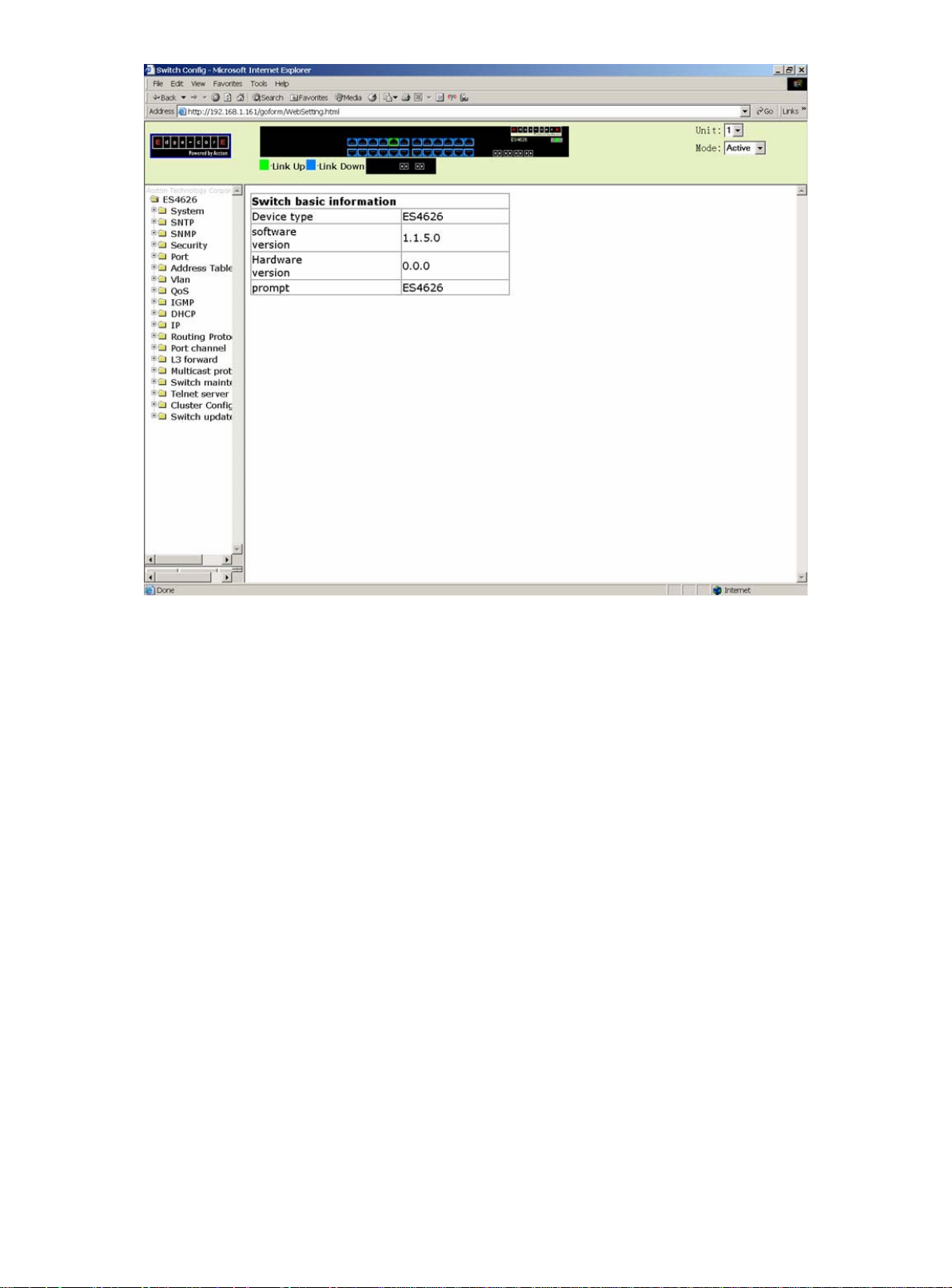
Fig 1-11 Main Web Configuration Interface
1.2 Management Interface
1.2.1 CLI Interface
CLI interface is familiar to most users. As aforementioned, out-of-band management
and Telnet login are all performed through CLI interface to manage the switch.
CLI Interface is supported by Shell program, which consists of a set of configuration
commands. Those commands are categorized according to their functions in switch
configuration and management. Each category represents a different configuration mode.
The Shell for the switch is described below:
z Configuration Modes
z Configuration Syntax
z Shortcut keys
z Help function
21
Page 22

A
z Input verification
z Fuzzy match support
1.2.1.1 Configuration Modes
User Mode
Admin Mode
Global Mode
Interface Mode
Fig 1-12 Shell Configuration Modes
Vlan Mode
DHCP address pool
configuration mode
Route configuration
mode
CL configuration
mode
1.2.1.1.1 User Mode
On entering the CLI interface, entering user entry system first. If as common user, it is
defaulted to User Mode. The prompt shown is “Switch>”, the symbol “>” is the prompt for
User Mode. When disable command is run under Admin Mode, it will also return to the
User Mode.
Under User Mode, no configuration to the switch is allowed, only clock time and
version information of the switch can be queries.
1.2.1.1.2 Admin Mode
To enter Under Admin Mode see the following: In user entry system, if as Admin user,
it is defaulted to Admin Mode. Admin Mode prompt “Switch#” can be entered under the
User Mode by running the enable command and entering corresponding access levels
admin user password, if a password has set. Or, when exit command is run under Global
22
Page 23

Mode, it will also return to the Admin Mode. ES4626/ES4650 also provides a shortcut key
sequence "Ctrl+z”, this allows an easy way to exit to Admin Mode from any configuration
mode (except User Mode).
Under Admin Mode, when disable command is run, it will return to User Mode. When
exit command is run, it will exit the entry and enter user entry system direct. Next users
can reenter the system on entering corresponding user name and password.
Under Admin Mode, the user can query the switch configuration information,
connection status and traffic statistics of all ports; and the user can further enter the Global
Mode from Admin Mode to modify all configurations of the switch. For this reason, a
password must be set for entering Admin mode to prevent unauthorized access and
malicious modification to the switch.
1.2.1.1.3 Global Mode
Type the config command under Admin Mode will enter the Global Mode prompt
“Switch(Config)#”. Use the exit command under other configuration modes such as
Interface Mode, VLAN mode will return to Global Mode.
The user can perform global configuration settings under Global Mode, such as MAC
Table, Port Mirroring, VLAN creation, IGMP Snooping start, GVRP and STP, etc. And the
user can go further to Interface Mode for configuration of all the interfaces.
1.2.1.1.3.1 Interface Mode
Use the interface command under Global Mode can enter the interface mode
specified. ES4626/ES4650 provides three interface type: VLAN interface, Ethernet port
and port-channel, and accordingly the three interface configuration modes.
Interface Type Entry Prompt Operates Exit
VLAN
Interface
Type interface
vlan <Vlan-id>
command under
Global Mode.
Switch(Config-IfVlanx)#
Configure
switch IPs, etc
Use the exit
command to
return to
Global Mode.
Ethernet Port Type interface
ethernet
<interface-list>
command under
Global Mode.
port-channel Type interface Switch(Config-if- Configure Use the exit
Switch(Configethernetxx)#
23
Configure
supported
duplex mode,
speed, etc.
of Ethernet
Port.
Use the exit
command to
return to
Global Mode.
Page 24

port-channel
<port-channel-nu
mber> command
under Global
Mode.
port-channelx)# port-channel
related
settings such
as duplex
mode, speed,
etc.
command to
return to
Global Mode.
1.2.1.1.3.2 VLAN Mode
Using the vlan <vlan-id> command under Global Mode can enter the corresponding
VLAN Mode. Under VLAN Mode the user can configure all member ports of the
corresponding VLAN. Run the exit command to exit the VLAN Mode to Global Mode.
1.2.1.1.3.3 DHCP Address Pool Mode
Type the ip dhcp pool <name> command under Global Mode will enter the DHCP
Address Pool Mode prompt “Switch(Config-<name>-dhcp)#”. DHCP address pool
properties can be configured under DHCP Address Pool Mode. Run the exit command to
exit the DHCP Address Pool Mode to Global Mode.
1.2.1.1.3.4 Route Mode
Routing
Protocol
RIP
Routing
Protocol
OSPF
Routing
Protocol
Entry Prompt Operates Exit
Type router
rip
command
under
Global
Mode.
Type router
ospf
command
under
Switch(Config-Router-Rip)# Configure
RIP protocol
parameters.
Switch(Config-Router-Ospf)# Configure
OSPF
protocol
parameters.
Use the
“exit”
command to
return to
Global
Mode.
Use the
“exit”
command to
return to
Global
Mode.
24
Global
Mode.
Page 25

1.2.1.1.3.5 ACL Mode
ACL type Entry Prompt Operates Exit
Standard IP
ACL Mode
Extended IP
ACL Mode
Type
access-list ip
command
under Global
Mode.
Type
access-list ip
command
under Global
Mode.
Switch(Config-Std-Nacla)#
Switch(Config-Ext-Naclb)#
Configure
parameters
for
Standard
IP ACL
Mode
Configure
parameters
for
Extended
IP ACL
Mode
Use the “exit”
command to
return to
Global Mode.
Use the “exit”
command to
return to
Global Mode.
1.2.1.2 Configuration Syntax
ES4626/ES4650 provides various configuration commands. Although all the
commands are different, they all abide by the syntax for ES4626/ES4650 configuration
commands. The general command format of ES4626/ES4650 is shown below:
cmdtxt <variable> { enum1 | … | enumN } [option]
Conventions: cmdtxt in bold font indicates a command keyword; <variable> indicates a
variable parameter; {enum1 | … | enumN } indicates a mandatory parameter that should
be selected from the parameter set enum1~enumN; and the square bracket ([ ]) in
[option] indicate a optional parameter. There may be combinations of “< >”, “{ }” and “[ ]”
in the command line, such as [<variable>],{enum1 <variable>| enum2}, [option1
[option2]], etc.
Here are examples for some actual configuration commands:
y show calendar, no parameters required. This is a command with only a
keyword and no parameter, just type in the command to run.
y vlan <vlan-id>, parameter values are required after the keyword.
y duplex {auto|full|half},user can enter duplex half, duplex full or duplex
auto for this command.
y snmp-server community <string>{ro|rw}, the followings are possible:
snmp-server community <string> ro
snmp-server community <string> rw
25
Page 26

1.2.1.3 Shortcut Key Support
ES4626/ES4650 provides several shortcut keys to facilitate user configuration, such
as up, down, left, right and Blank Space. If the terminal does not recognize Up and Down
keys, ctrl+p and ctrl+n can be used instead.
Key(s) Function
BackSpace Delete a character before the cursor, and the cursor moves back.
Up “↑” Show previous command entered. Up to ten recently entered
commands can be shown.
Down “↓” Show next command entered. When use the Up key to get
previously entered commands, you can use the Down key to return
to the next command
Left “←” The cursor move one character to
the left.
Right “→” The cursor moves one character to
the right.
Ctr+p The same as Up key “↑”.
Ctr+n The same as Down key “↓”.
Ctr+b The same as Left key “←”.
Ctr+f The same as Right key “→”.
Ctr+z Return to the Admin Mode directly from the other configuration
modes ( except User Mode).
Ctr+c Break the ongoing command process, such as ping or other
command execution.
Tab When a string for a command or keyword is entered, the Tab can
be used to complete the command or keyword if there is no
conflict.
You can use the Left and
Right key to modify an
entered command.
1.2.1.4 Help function
There are two ways in ES4626/ES4650 for the user to access help information: the
“help” command and the “?”.
Access to Help Usage and function
Help Under any command line prompt, type in “help” and press Enter will get
a brief description of the associated help system.
26
Page 27

“?” 1. Under any command line prompt, enter “?” to get a command
list of the current mode and related brief description.
2. Enter a “?” after the command keyword with a embedded
space. If the position should be a parameter, a description of
that parameter type, scope, etc, will be returned; if the position
should be a keyword, then a set of keywords with brief
description will be returned; if the output is “<cr>”, then the
command is complete, press Enter to run the command.
3. A “?” immediately following a string. This will display all the
commands that begin with that string.
1.2.1.5 Input verification
1.2.1.5.1 Returned Information: success
All commands entered through keyboards undergo syntax check by the Shell.
Nothing will be returned if the user entered a correct command under corresponding
modes and the execution is successful.
1.2.1.5.2 Returned Information: error
Output error message Explanation
Unrecognized command or illegal
parameter!
Ambiguous command At least two interpretations is possible basing on
Invalid command or parameter The command is recognized, but no valid
This command is not exist in current
mode
Please configure precursor
command "*" at first !
syntax error : missing '"' before the
end of command line!
The entered command does not exist, or there is
error in parameter scope, type or format.
the current input.
parameter record is found.
The command is recognized, but this command
can not be used under current mode.
The command is recognized, but the
prerequisite command has not been configured.
Quotation marks are not used in pairs.
1.2.1.6 Fuzzy match support
27
Page 28

ES4626/ES4650 Shell support fuzzy match in searching command and keyword.
Shell will recognize commands or keywords correctly if the entered string causes no
conflict.
For example:
1. For Admin configuration command “show interfaces status ethernet 1/1”,
typing “sh in status e 1/1” will work
2. However, for Admin configuration command “show running-config”, the
system will report a “> Ambiguous command!” error if only “show r” is
entered, as Shell is unable to tell whether it is “show rom” or “show
running-config”. Therefore, Shell will only recognize the command if “sh ru”
is entered.
1.2.2 WEB Interface
ES4626/ES4650 has HTTP Web management function. Users can configure and
examine the switch through a Web browser.
By conducting the following configurations, users can realize the Web management.
1. Configure valid IP address, network mask and default gateway for the switch.
See 5.3
2. Configure management user name and password.
3. Establish a connection to the switch through Web browser. Input username and
password. Then users can manage the switch through Web browser.
1.2.2.1 Main page
After passing the authentication by inputting username and password, users can see
the management page as below. On the management page, the main menu is on the left
and the system information and parameters are shown on the right. Click the links on the
main menu, users can see the corresponding configuration statistics.
28
Page 29
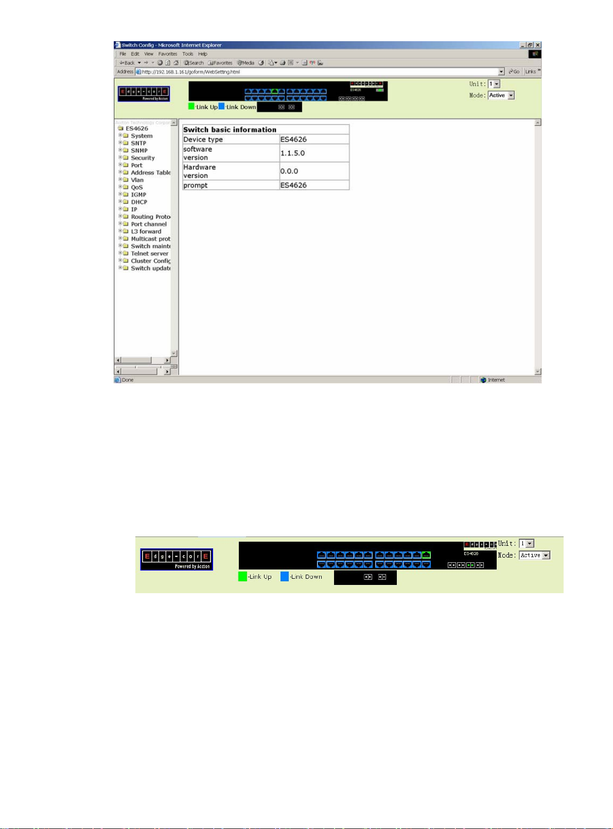
1.2.2.2 Interface Panel
On the top of the management page, the switch interface shows the current status of
the ports. Click the ports which are in the state of “Link Up”, the port statistics are shown
on the right.
29
Page 30

Chapter 2 Basic Switch Configuration
2.1 Basic Switch Configuration Commands
The basic configuration for the switch including all the commands for entering and
exiting the Admin Mode and Interface Mode, setting and displaying switch clock and
displaying system version information.
2.1.1 calendar set
Command: calendar set <HH> <MM> <SS> {<DD> <MON> <YYYY> | <MON> <DD>
<YYYY>}
Function: Set system date and time.
Parameter: <HH> <MM> <SS> is the current time, and the valid scope for HH is 0 to 23,
MM and SS 0 to 59; <DD> <MON> <YYYY> or <MON> <DD> <YYYY> is the current date,
month and year or the current year, month and date, and the valid scope for YYYY is
1970~2100, MON meaning month, and DD between 1 to 31.
Command mode: Admin Mode
Default: upon first time start-up, it is defaulted to 2001.1.1 0: 0: 0.
Usage guide: The switch can not continue timing with power off, hence the current date
and time must be first set at environments where exact time is required.
Example: To set the switch current date and time to 2002.8.1 23: 0: 0:
Switch# calendar set 23 0 0 august 1 2002Related command: show calendar
2.1.2 config
Command: config [terminal]
Function: Enter Global Mode from Admin Mode.
Parameter: [terminal] indicates terminal configuration.
Command mode: Admin Mode
Example:
Switch#config
30
Page 31

2.1.3 enable
Command: enable
Function: Enter Admin Mode from User Mode.
Parameter: 0 and 15 are user access levels. 0 is normal user level. In this level, users can
enter Admin Mode and conduct major commands such as show, ping and traceroute etc.
But users can‘t enter Global Mode. 15 is privileged user level. In this level, users can
conduct all the command of this level. <password> is password for logging on to the
privileged user mode.
Command mode: User Mode
Default: If users don’t specify the level, the default level is 15.
Usage Guide: To prevent unauthorized access of non-admin user, user authentication is
required (i.e. Admin user password is required) when entering Admin Mode from User
Mode. If the correct Admin user password is entered, Admin Mode access is granted; if 3
consecutive entry of Admin user password are all wrong, it remains in the User Mode. Set
the Admin user password under Global Mode with “enable password” command.
Example:
Switch>enable
password: ***** (admin)
Switch#
Related command: enable password
2.1.4 disable
Command: disable
Function: Enter User Mode from Admin Mode.
Command mode: Admin Mode
Example:
Switch#disable
Switch>
Related command: enable
2.1.5 enable password
Command: enable password[level {0 | 15}]
31
Page 32

Function: Modify the password to enter Admin Mode from the User Mode, press Enter
after type in this command displays <Current password> and <New password>
parameter for the users to configure.
Parameter: 0 is normal user access level, users can enter Admin Mode and conduct
major commands such as show, ping and trace route etc. But users can‘t enter Global
Mode. 15 is privileged user level. In this level, users can conduct all the command of this
level. <Current password> is the original password, up to 16 characters are allowed;
<New password> is the new password, up to 16 characters are allowed; <Confirm new
password> is to confirm the new password and should be the same as <New
password>, otherwise, the password will need to be set again.
Command mode: Global Mode
Default: If users don’t specify the level, the default level is 15,upon first time start-up, the
Admin user password is empty. If this is the first configuration, simply press Enter on
prompting for current password.
Usage Guide: Configure Admin user password to prevent unauthorized access from
non-admin user. It is recommended to set the Admin user password at the initial switch
configuration. Also, it is recommended to exit Admin Mode with “exit” command when the
administrator needs to leave the terminal for a long time.
Example: Set the Admin user password to “admin”.
Switch(Config)#enable password
Current password: (First time configuration, no password set, just press Enter)
New password: ***** (Type in admin to set the new password to “admin”)
Confirm New password: ***** (Type admin again to confirm the new password)
Switch(Config)#
Related command: enable
2.1.6 exec timeout
Command: exec timeout <minutes >
Function: Set timeout value for exiting Admin Mode
Parameter: < minute > is the time in minutes, the valid range is 0 to 300.
Command mode: Global Mode
Default: The default value is 5 minutes.
Usage Guide: To ensure security for the switch and prevent malicious operation of
unauthorized user, timeout count will start after the last configuration by the Admin user.
And the system will automatically exit the Admin Mode upon preset timeout threshold. If
the user needs to enter Admin Mode, Admin user password needs to be entered again. A
32
Page 33

0 exec timeout value indicate the system will never exit Admin Mode automatically.
Example: Set timeout value for the switch to exit Admin Mode to 6 minutes.
Switch(Config)#exec timeout 6
2.1.7 exit
Command: exit
Function: Exit the current mode to the previous mode. Under Global Mode, this
command will return the user to Admin Mode, and in Admin Mode to User Mode, etc.
Command mode: All configuration modes.
Example:
Switch#exit
Switch>
2.1.8 help
Command: help
Function: Output brief description of the command interpreter help system.
Command mode: All configuration modes.
Usage Guide: An instant online help provided by the switch. Help command displays
information about the whole help system, including complete help and partial help. The
user can type in ? any time to get online help.
Example:
Switch>help
enable -- Enable Privileged mode
exit -- Exit telnet session
help -- help
show -- Show running system information
2.1.9 ip host
Command: ip host <hostname> <ip_addr>
no ip host <hostname>
Function: Set the mapping relationship between the host and IP address; the “no ip host”
33
Page 34

parameter of this command will delete the mapping.
Parameter: <hostname> is the host name, up to 15 characters are allowed; <ip_addr> is
the corresponding IP address for the host name, takes a dot decimal format.
Command mode: Global Mode
Usage Guide: Set the association between host and IP address, which can be used in
commands like “ping <host>”.
Example: Set IP address of a host with the hostname of “beijing” to 200.121.1.1.
Switch(Config)#ip host beijing 200.121.1.1
Related commands: telnet、ping、traceroute
2.1.10 hostname
Command: hostname <hostname>
Function: Set the prompt in the switch command line interface.
Parameter <hostname> is the string for the prompt, up to 30 characters are allowed.
Command mode: Global Mode
Default: The default prompt is ES4626/ES4650.
Usage Guide: With this command, the user can set the command line prompt of the
switch according to their own requirements.
Example: Set the prompt to “Test”.
Switch(Config)#hostname Test
Test(Config)#
2.1.11 username password
Command: username <user_name> password <show_flag> <pass_word>
no uername <user_name>
Function: Configure username and password for logging on the switch; the “no
username <user_name>” command deletes the user.
Parameter: <user_name> is the username. It can’t exceed 16 characters; <show_flag>
can be either 0 or 7. 0 is used to display unencrypted username and password, whereas 7
is used to display encrypted username and password; <pass_word> is password. It can’t
exceed 16 characters;
Command mode: Global Mode
Default: The username and password are null by default.
Usage Guide: This command can be used to set the username for logging on the switch
and set the password as null.
34
Page 35

Example: Set username as “admin” and set password as “admin”
Switch(Config)#username admin password 0 admin
Switch(Config)#
Related Command: username nopassword、username access-level、show users
2.1.12 username nopassword
Command: username <user_name> nopassword
Function: Set the username for logging on the switch and set the password as null.
Parameter: <user_name> is the username. It can’t exceed 16 characters.
Command mode: Global Mode
Usage Guide: This command is used to set the username for logging on the switch and
set the password as null.
Example: Set username as “admin” and set password as null.
Switch(Config)#username admin nopassword
Switch(Config)#
Related Command: username password、username access-level、show users
2.1.13 username access-level
Command: username <user_name> access-level <level>
Function: Configure the access level for users who log on the switch.
Parameter: <user_name> is the username. It can’t exceed 16 characters; <level> can be
either 0 or 15. 0 is normal user level and 15 is privileged user level.
Command mode: Global Mode
Example: Create user “admin” and set the level of this user as privileged user level.
Switch(Config)#username admin access-level 15
Switch(Config)#
Related Command: username password、username nopassword、show users
2.1.14 reload
Command: reload
Function: Warm reset the switch.
Command mode: Admin Mode
Usage Guide: The user can use this command to restart the switch without power off .
35
Page 36

2.1.15 set default
Command: set default
Function: Reset the switch to factory settings.
Command mode: Admin Mode
Usage Guide: Reset the switch to factory settings. That is to say, all configurations made
by the user to the switch will disappear. When the switch is restarted, the prompt will be
the same as when the switch was powered on for the first time.
Note: After the command, “write” command must be executed to save the operation. The
switch will reset to factory settings after restart.
Example:
Switch#set default
Are you sure? [Y/N] = y
Switch#write
Switch#reload
2.1.16 setup
Command: setup
Function: Enter the Setup Mode of the switch.
Command mode: Admin Mode
Usage Guide: ES4626/ES4650 provides a Setup Mode, in which the user can configure
IP addresses, etc.
2.1.17 language
Command: language {chinese|english}
Function: Set the language for displaying the help information.
Parameter: chinese for Chinese display; english for English display.
Command mode: Admin Mode
Default: The default setting is English display.
Usage Guide: ES4626/ES4650 provides help information in two languages, the user can
select the language according to their preference. After the system restart, the help
information display will revert to English.
2.1.18 write
36
Page 37

Command: write
Function: Save the currently configured parameters to the Flash memory.
Command mode: Admin Mode
Usage Guide: After a set of configuration with desired functions, the setting should be
saved to the Flash memory, so that the system can revert to the saved configuration
automatically in the case of accidentally powered down or power failure. This is the
equivalent to the copy running-config startup-config command.
Related commands: copy running-config startup-config
2.2 Maintenance and Debug Commands
When the users configures the switch, they will need to verify whether the
configurations are correct and the switch is operating as expected, and in network failure,
the users will also need to diagnostic the problem. ES4626/ES4650 provides various
debug commands including ping, telnet, show and debug, etc. to help the users to check
system configuration, operating status and locate problem causes.
2.2.1 ping
Command: ping [<ip-addr>]
Function: The switch send ICMP packet to remote devices to verify the connectivity
between the switch and remote devices.
Parameter: <ip-addr> is the target host IP address for ping, in dot decimal format.
Default: Send 5 ICMP packets of 56 bytes each, timeout in 2 seconds.
Command mode: Admin Mode
Usage Guide: When the user types in the ping command and press Enter, the system
will provide an interactive mode for configuration, and the user can choose all the
parameters for ping.
Example:
Example 1: Default parameter for ping.
Switch#ping 10.1.128.160
Type ^c to abort.
Sending 5 56-byte ICMP Echos to 10.1.128.160, timeout is 2 seconds.
...!!
Success rate is 40 percent (2/5), round-trip min/avg/max = 0/0/0 ms
As shown in the above example, the switch pings a device with an IP address of
10.1.128.160, three ICMP request packets sent without receiving corresponding reply
37
Page 38

packets (i.e. ping failed), the last two packets are replied successfully, the successful rate
is 40%. The switch represent ping failure with a “.”, for unreachable target; and ping
success with “!” , for reachable target.
Switch#ping
protocol [IP]:
Target IP address: 10.1.128.160
Repeat count [5]: 100
Datagram size in byte [56]: 1000
Timeout in milli-seconds [2000]: 500
Extended commands [n]: n
Displayed information Explanation
protocol [IP]: Select the ping for IP protocol
Target IP address: Target IP address
Repeat count [5] Packet number, the default is 5
Datagram size in byte [56] ICMP packet size the default is 56 bytes
Timeout in milli-seconds [2000]: Timeout (in milliseconds,) the default is 2
seconds.
Extended commands [n]: Whether to change the other options or not
2.2.2 Telnet
2.2.2.1 Introduction to Telnet
Telnet is a simple remote terminal protocol for remote login. Using Telnet, the user
can login to a remote host with its IP address of hostname from his own workstation.
Telnet can send the user’s keystrokes to the remote host and send the remote host output
to the user’s screen through TCP connection. This is a transparent service, as to the user,
the keyboard and monitor seems to be connected to the remote host directly.
Telnet employs the Client-Server mode, the local system is the Telnet client and the
remote host is the Telnet server. ES4626/ES4650 can be either the Telnet Server or the
Telnet client.
When ES4626/ES4650 is used as the Telnet server, the user can use the Telnet client
program included in Windows or the other operation systems to login to ES4626/ES4650,
as described earlier in the In-band management section. As a Telnet server,
ES4626/ES4650 allows up to 5 telnet client TCP connections.
And as Telnet client, use telnet command under Admin Mode allow the user to login
to the other remote hosts. ES4626/ES4650 can only establish TCP connection to one
38
Page 39

remote host. If a connection to another remote host is desired, the current TCP connection
must be dropped.
2.2.2.2 Telnet Task Sequence
1. Configuring Telnet Server
2. Telnet to a remote host from the switch.
1. Configuring Telnet Server
Command Explanation
Global Mode
ip telnet server
no ip telnet server
telnet-server securityip <ip-addr>
no telnet-server securityip <ip-addr>
Admin Mode
monitor
no monitor
2. Telnet to a remote host from the switch
Enable the Telnet server function in the
switch: the “no telnet-server enable”
command disables the Telnet function.
Configure the secure IP address to
login to the switch through Telnet: the
“no telnet-server securityip
<ip-addr>” command deletes the
authorized Telnet secur e address.
Display debug information for Telnet
client login to the switch; the “no
monitor” command disables the
debug information.
Command Explanation
Admin Mode
telnet [<ip-addr>] [<port>]
Login to a remote host with the Telnet
client included in the switch.
2.2.2.3 Telnet Commands
2.2.2.3.1 monitor
39
Page 40

Command: monitor
no monitor
Function: Enable debug information for Telnet client login to the switch, the Console end
debug display will be disabled at the same time; the “no monitor” command disables the
debug information and re-enables the Console end debug display. .
Command mode: Admin Mode
Usage Guide: When Telnet client accessing the switch enables Debug information, the
information is not shown in the Telnet interface, instead, it is displayed in the terminal
connecting to the Console port. This command specifies the debug information to be
displayed in the Telnet terminal screen instead of the Console or the other Telnet terminal
screens.
Example: Enable displaying the debug information in Telnet client.
Switch#monitor
2.2.2.3.2 telnet
Command: telnet [<ip-addr>] [<port>]
Function: Login to a remote host with an IP address of <ip-addr> through Telnet.
Parameter: <ip-addr> is the remote host IP address in dot decimal format. <port> is the
port number, valid value is 0 – 65535.
Command mode: Admin Mode
Usage Guide: This command is used when the switch is used as a client, the user logs in
to remote hosts for configuration with this command. ES4626/ES4650 can only establish
TCP connection to one remote host as the Telnet client. If a connection to another remote
host is desired, the current TCP connection must be dropped. To disconnect with a remote
host, the shortcut key combination “CTRL+|” can be used.
Input Telnet keyword without any parameter enters the Telnet configuration mode.
Example: Telnet to a remote router with the IP address 20.1.1.1 from the switch.
Switch#telnet 20.1.1.1 23
Connecting Host 20.1.1.123 Port 23...
Service port is 23
Connected to 20.1.1.123login: 123
password: ***
route>
2.2.2.3.3 ip telnet server
Command: ip telnet server
40
Page 41

no ip telnet server
Function: Enable the Telnet server function in the switch: the “no telnet-server enable”
command disables the Telnet function in the switch.
Default: Telnet server function is enabled by default.
Command mode: Global Mode
Usage Guide: This command is available in Console only. The administrator can use this
command to enable or disable the Telnet client to login to the switch.
Example: Disable the Telnet server function in the switch.
Switch(Config)#no telnet-server enable
2.2.2.3.4 telnet-server securityip
Command: telnet-server securityip <ip-addr>
no telnet-server securityip <ip-addr>
Function: Configure the secure IP address of Telnet client allowed to login to the switch;
the “no telnet-server securityip <ip-addr>” command deletes the authorized Telne t
secure address.
Parameter: <ip-addr> is the secure IP address allowed to access the switch, in dot
decimal format.
Default: no secure IP address is set by default.
Command mode: Global Mode
Usage Guide: When no secure IP is configured, the IP addresses of Telnet clients
connecting to the switch will not be limited; if a secure IP address is configured, only hosts
with the secure IP address is allowed to connect to the switch through Telnet for
configuration. The switch allows multiple secure IP addresses.
Example: Set 192.168.1.21 as a secure IP address.
Switch(Config)#telnet-server securityip 192.168.1.21
2.2.3 SSH
2.2.3.1 Introduction to SSH
SSH (Secure Shell) is a protocol which ensures a secure remote access connection
to network devices. It is based on the reliable TCP/IP protocol. By conducting the
mechanism such as key distribution, authentication and encryption between SSH server
and SSH client, a secure connection is established. The information transferred on this
41
Page 42

connection is protected from being intercepted and decrypted. The switch meets the
requirements of SSH2.0. It supports SSH2.0 client software such as SSH Secure Client
and putty. Users can run the above software to manage the switch remotely.
The switch presently supports RSA authentication, 3DES cryptography protocol and
SSH user password authentication etc.
2.2.3.2 SSH Server Configuration Sequence
1. SSH Server Configuration
Command Explanation
Global Mode
ssh-server enable
no ssh-server enable
ssh-user <user-name> password {0|7}
<password>
no ssh-user <user-name>
ssh-server timeout <timeout>
no ssh-server timeout
ssh-server authentication-retires <
authentication-retires>
no ssh-server authentication-retries
ssh-server host-key create rsa
Enable SSH function on the switch; the
“no ssh-server enable” command
disables SSH function.
Configure the username and password of
SSH client software for logging on the
switch; the “no ssh-user <user-name>”
command deletes the username.
Configure timeout value for SSH
authentication; the “no ssh-server
timeout” command restores the default
timeout value for SSH authentication.
Configure the number of times for retrying
SSH authentication; the “no ssh-server
authentication-retries” command
restores the default number of times for
retrying SSH authentication.
Generate the new RSA host key on the
modulus <moduls>
Admin Mode
monitor
no monitor
SSH server.
Display SSH debug information on the
SSH client side; the “no monitor”
command stops displaying SSH debug
information on the SSH client side.
2.2.3.3 SSH Configuration Commands
42
Page 43

2.2.3.3.1 ssh-server enable
Command: ssh-server enable
no ssh-server enable
Function: Enable SSH function on the switch; the “no ssh-server enable” command
disables SSH function.
Command mode: Global Mode
Default: SSH function is disabled by default.
Usage Guide: In order that the SSH client can log on the switch, the users need to
configure the SSH user and enable SSH function on the switch.
Example: Enable SSH function on the switch.
Switch(Config)#ssh-server enable
2.2.3.3.2 ssh-user
Command: ssh-user <username> password {0|7} <password>
no ssh-user <username>
Function: Configure the username and password of SSH client software for logging on
the switch; the “no ssh-user <user-name>” command deletes the username.
Parameter: <username> is SSH client username. It can’t exceed 16 characters;
<password> is SSH client password. It can’t exceed 8 characters; 0|7 stand for
unencrypted password and encrypted password.
Command mode: Global Mode
Default: There are no SSH username and password by default.
Usage Guide: This command is used to configure the authorized SSH client. Any
unauthorized SSH clients can’t log on and configure the switch. When the switch is a
SSH server, it can have maximum three users and it allows maximum three users to
connect to it at the same time.
Example: Set a SSH client which has “switch” as username and “switch” as password.
Switch(Config)#ssh-user switch password 0 switch
2.2.3.3.3 ssh-server timeout
Command: ssh-server timeout <timeout>
no ssh-server timeout
Function: Configure timeout value for SSH authentication; the “no ssh-server timeout”
command restores the default timeout value for SSH authentication.
43
Page 44

Parameter: <timeout> is timeout value; valid range is 10 to 600 seconds.
Command mode: Global Mode
Default: SSH authentication timeout is 180 seconds by default.
Example: Set SSH authentication timeout to 240 seconds.
Switch(Config)#ssh-server timeout 240
2.2.3.3.4 ssh-server authentication-retries
Command: ssh-server authentication-retries < authentication-retries >
no ssh-server authentication-retries
Function: Configure the number of times for retrying SSH authentication; the “no
ssh-server authentication-retries” command restores the default number of times for
retrying SSH authentication.
Parameter: < authentication-retries > is the number of times for retrying authentication;
valid range is 1 to 10.
Command mode: Global Mode
Default: The number of times for retrying SSH authentication is 3 by default.
Example: Set the number of times for retrying SSH authentication to 5.
Switch(Config)#ssh-server authentication-retries 5
2.2.3.3.5 ssh-server host-key create rsa
Command: ssh-server host-key create rsa [modulus < modulus >]
Function: Generate new RSA host key
Parameter: modulus is the modulus which is used to compute the host key; valid range
is 768 to 2048. The default value is 1024.
Command mode: global Mode
Default: The system uses the key generated when the ssh-server is started at the first
time.
Usage Guide: This command is used to generate the new host key. When SSH client
logs on the server, the new host key is used for authentication. After the new host key is
generated and “write” command is used to save the configuration, the system uses this
key for authentication all the time. Because it takes quite a long time to compute the new
key and some clients are not compatible with the key generated by the modulus 2048, it
is recommended to use the key which is generated by the default modulus 1024.
Example: Generate new host key.
Switch(Config)#ssh-server host-key create rsa
44
Page 45

2.2.3.3.6 monitor
Command: monitor
no monitor
Function: Display SSH debug information on the SSH client side and stop displaying
SSH debug information on the Console; the “no monitor” command stops displaying
SSH debug information on the SSH client side and enables to display SSH debug
information on the Console.
Command mode: Admin Mode
Usage Guide: When SSH client accesses the switch and users enable to display SSH
Debug information, this information is displayed on the Console terminal instead of SSH
interface. This command enables debug information to be displayed on the SSH
interface instead of on the Console terminal.
Example: Enable to display SSH debug information on the SSH client interface.
Switch#monitor
Related command: ssh-user
2.2.3.4 Typical SSH Server Configuration
Example 1:
Requirement: Enable SSH server on the switch, and run SSH2.0 client software such
as Secure shell client and putty on the terminal. Log on the switch by using the username
and password from the client.
Configure the IP address, add SSH user and enable SSH service on the switch.
SSH2.0 client can log on the switch by using the username and password to configure the
switch.
Switch(Config)#interface vlan 1
Switch(Config-Vlan-1)#ip address 100.100.100.200 255.255.255.0
Switch(Config-Vlan-1)#exit
Switch(Config)#ssh-user test password 0 test
Switch(Config)#ssh-server enable
2.2.3.5 SSH Monitor and Debug Commands
45
Page 46

2.2.3.5.1 show ssh-user
Command: show ssh-user
Function: Display the configured SSH usernames.
Parameter: Admin Mode
Example:
Switch#show ssh-user
test
Related command: ssh-user
2.2.3.5.2 show ssh-server
Command: show ssh-server
Function: Display SSH state and users which log on currently.
Command mode: Admin Mode
Example:
Switch#show ssh-server
ssh-server is enabled
connection version state user name
1 2.0 session started test
Related command: ssh-server enable, no ssh-server enable
2.2.3.5.3 debug ssh-server
Command: debug ssh-server
no debug ssh-server
Function: Display SSH server debugging information; the “no debug ssh-server”
command stops displaying SSH server debugging information.
Default: This function is disabled by default.
Command mode: Admin Mode
2.2.4 traceroute
Command: traceroute {<ip-addr> | host <hostname> }[hops <hops>] [timeout
<timeout> ]
Function: This command is tests the gateway passed in the route of a packet from the
source device to the target device. This can be used to test connectivity and locate a failed
46
Page 47

sector.
Parameter: <ip-addr> is the target host IP address in dot decimal format. <hostname> is
the hostname for the remote host. <hops> is the maximum gateway number allowed by
Traceroute command. <timeout> Is the timeout value for test packets in milliseconds,
between 100 – 10000.
Default: The default maximum gateway number is 16, timeout in 2000 ms.
Command mode: Admin Mode
Usage Guide: Traceroute is usually used to locate the problem for unreachable network
nodes.
Related command: ip host
2.2.5 show
show command is used to display information about the system , port and protocol
operation. This part introduces the show command that displays system information,
other show commands will be discussed in other chapters.
2.2.5.1 show calendar
Command: show calendar
Function: Display the system clock.
Command mode: Admin Mode
Usage Guide: The user can use this command to check system date and time so that the
system clock can be adjusted in time if inaccuracy occurs.
Example:
Switch#show calendar
Current time is TUE AUG 22 11: 00: 01 2002
Related command: calendar set
2.2.5.2 show debugging
Command: show debugging
Function: Display the debug switch status.
Usage Guide: If the user need to check what debug switches have been enabled, show
debugging command can be executed.
47
Page 48

Command mode: Admin Mode
Example: Check for currently enabled debug switch.
Switch#show debugging
STP:
Stp input packet debugging is on
Stp output packet debugging is on
Stp basic debugging is on
Switch#
Related command: debug
2.2.5.3 dir
Command: dir
Function: Display the files and their sizes in the Flash memory.
Command mode: Admin Mode
Example: Check for files and their sizes in the Flash memory.
Switch#dir
boot.rom 329,828 1900-01-01 00: 00: 00 --SH
boot.conf 94 1900-01-01 00: 00: 00 --SH
nos.img 2,449,496 1980-01-01 00: 01: 06 ----
startup-config 2,064 1980-01-01 00: 30: 12 ----
2.2.5.4 show history
Command: show history
Function: Display the recent user command history,.
Command mode: Admin Mode
Usage Guide: The system holds up to 10 commands the user entered, the user can use
the UP/DOWN key or their equivalent (ctrl+p and ctrl+n) to access the command history.
Example:
Switch#show history
enable
config
interface ethernet 1/3
enable
dir
show ftp
48
Page 49

2.2.5.5 show memory
Command: show memory
Function: Display the contents in the memory.
Command mode: Admin Mode
Usage Guide: This command is used for switch debug purposes. The command will
interactively prompt the user to enter start address of the desired information in the
memory and output word number. The displayed information consists of three parts:
address, Hex view of the information and character view.
Example:
Switch#show memory
start address : 0x2100
number of words[64]:
002100: 0000 0000 0000 0000 0000 0000 0000 0000 *................*
002110: 0000 0000 0000 0000 0000 0000 0000 0000 *................*
002120: 0000 0000 0000 0000 0000 0000 0000 0000 *................*
002130: 0000 0000 0000 0000 0000 0000 0000 0000 *................*
002140: 0000 0000 0000 0000 0000 0000 0000 0000 *................*
002150: 0000 0000 0000 0000 0000 0000 0000 0000 *................*
002160: 0000 0000 0000 0000 0000 0000 0000 0000 *................*
002170: 0000 0000 0000 0000 0000 0000 0000 0000 *................*
2.2.5.6 show running-config
Command: show running-config
Function: Display the current active configuration parameters for the switch.
Default: If the active configuration parameters are the same as the default operating
parameters, nothing will be displayed.
Command mode: Admin Mode
Usage Guide: When the user finishes a set of configuration and needs to verify the
configuration, show running-config command can be used to display the current active
parameters.
Example:
Switch#show running-config
49
Page 50

2.2.5.7 show startup-config
Command: show startup-config
Function: Display the switch parameter configurations written into the Flash memory at
the current operation, those are usually also the configuration files used for the next
power-up.
Default: If the configuration parameters read from the Flash are the same as the default
operating parameter, nothing will be displayed.
Command mode: Admin Mode
Usage Guide: The show running-config command differs from show startup-config in
that when the user finishes a set of configurations, show running-config displays the
added-on configurations whilst show startup-config won’t display any configurations.
However, if write command is executed to save the active configuration to the Flash
memory, the displays of show running-config and show startup-config will be the
same.
2.2.5.8 show interfaces switchport
Command: show interfaces switchport [ethernet <interface >]
Function: Display VLAN interface mode and VLAN number, and Trunk port information
for the switch.
Parameter: <interface > is the port number, which can be any port information exist in the
switch.
Command mode: Admin Mode
Example: Display the VLAN information for interface ethernet 1/1.
Switch#show interfaces swichport ethernet 1/1
Ethernet1/1
Type : Universal
Mac addr num : -1
Mode : Access
Port VID : 1
Trunk allowed Vlan : ALL
Displayed information Description
Ethernet1/1 Corresponding Ethernet interface number;
Type Current Interface Type
Mac addr num MAC address number can be learn by the current
interface
Mode : Access VLAN mode of the current Interface
50
Page 51

Port VID : 1 VLAN number belong to the current Interface
Trunk allowed Vlan : ALL VLAN allowed to be crossed by Trunk.
2.2.5.9 show tcp
Command: show tcp
Function: Display the current TCP connection status established to the switch.
Command mode: Admin Mode
Example:
Switch#show tcp
LocalAddress LocalPort ForeignAddress ForeignPort State
0.0.0.0 23 0.0.0.0 0 LISTEN
0.0.0.0 80 0.0.0.0 0 LISTEN
Displayed information Description
LocalAddress
LocalPort
ForeignAddress
ForeignPort
State
Local address of the TCP connection.
Local pot number of the TCP connection.
Remote address of the TCP connection.
Remote port number of the TCP connection.
Current status of the TCP connection.
2.2.5.10 show udp
Command: show udp
Function: Display the current UDP connection status established to the switch.
Command mode: Admin Mode
Example:
Switch#show udp
LocalAddress LocalPort ForeignAddress ForeignPort State
0.0.0.0 161 0.0.0.0 0 CLOSED
0.0.0.0 123 0.0.0.0 0 CLOSED
0.0.0.0 1985 0.0.0.0 0 CLOSED
Displayed information Description
LocalAddress
LocalPort
ForeignAddress
ForeignPort
State
Local address of the udp connection.
Local pot number of the udp connection.
Remote address of the udp connection.
Remote port number of the udp connection.
Current status of the udp connection.
51
Page 52

2.2.5.11 show users
Command: show users
Function: Display all user information that can login the switch .
Usage Guide: This command can be used to check for all user information that can login
the switch .
Example:
Switch#show users
User level havePasword
admin 0 1
Online user info: user ip login time(second) usertype
Switch#
Related command: username password、username access-level
2.2.5.12 show version
Command: show version<unit>
Parameter: where the range of unit is 1
Function: Display the switch version.
Default: The default value for <unit> is 1
Command mode: Admin Mode
Usage Guide: Use this command to view the version information for the switch, including
hardware version and software version. 。
Example:
Switch#show vers
ES4626 Device, Apr 14 2005 11: 19: 29
HardWare version is 2.0, SoftWare version packet is ES4626_1.1.0.0, BootRom version
is ES4626_1.0.4
Copyright (C) 2001-2006 by Accton Technology Corporation..
All rights reserved.
Last reboot is cold reset
Uptime is 0 weeks, 0 days, 0 hours, 28 minutes
52
Page 53

2.2.6 debug
All the protocols ES4626/ES4650 supports have their corresponding debug
commands. The users can use the information from debug command for troubleshooting.
Debug commands for their corresponding protocols will be introduced in the later
chapters.
2.3 Configuring Switch IP Addresses
All Ethernet ports of ES4626/ES4650 is default to DataLink layer ports and perform
layer 2 forwarding. VLAN interface represent a Layer 3 interface function , which can be
assigned an IP address, which is also the IP address of the switch. All VLAN interface
related configuration commands can be configured under VLAN Mode. ES4626/ES4650
provides three IP address configuration methods:
& Manual
& BootP
& DHCP
Manual configuration of IP address is assign an IP address manually for the switch.
In BootP/DHCP mode, the switch operates as a BootP/DHCP client, send broadcast
packets of BootPRequest to the BootP/DHCP servers, and the BootP/DHCP servers
assign the address on receiving the request. In addition, ES4626/ES4650 can act as a
DHCP server, and dynamically assign network parameters such as IP addresses,
gateway addresses and DNS server addresses to DHCP clients DHCP Server
configuration is detailed in later chapters.
2.3.1 Configuring Switch IP Addresses Task Sequence
1. Manual configuration
2. BootP configuration
3. DHCP configuration
1. Manual configuration
Command Explanation
ip address <ip_address> <mask>
[secondary]
Configure the VLAN interface IP address;
the “no ip address <ip_address> <mask>
53
Page 54

no ip address <ip_address> <mask>
[secondary]
2. BootP configuration
Command Explanation
ip address bootp
no ip address bootp
3.DHCP
Command Explanation
ip address dhcp
no ip address dhcp
[secondary]” command deletes VLAN
interface IP address.
Enable the switch to be a BootP client and
obtain IP address and gateway address
through BootP negotiation; the “no ip
bootp-client enable” command disables
the BootP client function.
Enable the switch to be a DHCP client and
obtain IP address and gateway address
through DHCP negotiation; the “no ip
dhcp-client enable” command disables
the DHCP client function.
2.3.2 Commands for Configuring Switch IP
Addresses
2.3.2.1 ip address
Command: ip address <ip-address> <mask> [secondary]
no ip address [<ip-address> <mask>] [secondary]
Function: Set the IP address and mask for the specified VLAN interface; the “no ip
address <ip address> <mask> [secondary]” command deletes the specified IP address
setting.
Parameter: <ip-address> is the IP address in dot decimal format; <mask> is the subnet
mask in dot decimal format; [secondary] indicates the IP configured is a secondary IP
address.
Default: No IP address is configured upon switch shipment.
Command mode: VLAN Interface Mode
Usage Guide: A VLAN interface must be created first before the user can assign an IP
address to the switch.
Example: Set 10.1.128.1/24 as the IP address of VLAN1 interface.
54
Page 55

Switch(Config)#interface vlan 1
Switch(Config-If-Vlan1)#ip address 10.1.128.1 255.255.255.0
Switch(Config-If-Vlan1)#exit
Switch(Config)#
Related command: ip address bootp、ip address dhcp
2.3.2.2 ip address bootp
Command: ip address bootpno ip address bootp
Function: Enable the switch to be a BootP client and obtain IP address and gateway
address through BootP negotiation; the “no ip bootp-client enable” command disables
the BootP client function and releases the IP address obtained in BootP .
Default: BootP client function is disabled by default.
Command mode: VLAN Interface Mode
Usage Guide: Obtaining IP address through BootP, Manual configuration and DHCP are
mutually exclusive, enabling any 2 methods for obtaining IP address is not allowed. Note:
To obtain IP address via DHCP, a DHCP server or a BootP server is required in the
network.
Example: Get IP address through BootP.
Switch(Config)#interface vlan 1
Switch(Config-If-Vlan1)# ip address bootp
Switch (Config-If-Vlan1)#exit
Switch (Config)#
Related command: ip address、ip address dhcp
2.3.2.3 ip address dhcp
Command: ip address dhcp
no ip address dhcp
Function: Enable the switch to be a DHCP client and obtain IP address and gateway
address through DHCP negotiation; the “no ip dhcp -client enable” command disables
the DHCP client function and releases the IP address obtained in DHCP . Note: To obtain
IP address via DHCP, a DHCP server is required in the network.
Default: DHCP client function is disabled by default.
Command mode: VLAN Interface Mode
Usage Guide: Obtaining IP address through DHCP, Manual configuration and BootP are
mutually exclusive, enabling any 2 methods for obtaining IP address is not allowed.
Example: Get IP address through DHCP.
55
Page 56

Switch (Config)#interface vlan 1
Switch (Config-If-Vlan1)# ip address dhcp
Switch (Config-If-Vlan1)#exit
Switch (Config)#
Related command: ip address, ip address bootp
2.4 SNMP
2.4.1 Introduction to SNMP
SNMP (Simple Network Management Protocol) is a standard network management
protocol widely used in computer network management. SNMP is an evolving protocol.
SNMP v1 [RFC1157] is the first version of SNMP which is adapted by vast numbers of
manufacturers for its simplicity and easy implementation; SNMP v2c is an enhanced
version of SNMP v1, which supports layered network management; SNMP v3 strengthens
the security by adding USM (User-based Security Mode) and VACM (View-based Access
Control Model).
SNMP protocol provides a simple way of exchange network management information
between two points in the network. SNMP employs a polling mechanism of message
query, and transmits messages through UDP (a connectionless transport layer protocol).
Therefore it is well supported by the existing computer networks.
SNMP protocol employs a station-agent mode. There are two parts in this structure:
NMS (Network Management Station) and Agent. NMS is the workstation on which SNMP
client program is running. It is the core on the SNMP network management. Agent is the
server software runs on the devices which need to be managed. NMS manages all the
managed objects through Agents. The switch supports Agent function.
The communication between NMS and Agent functions in Client/Server mode by
exchanging standard messages. NMS sends request and the Agent responds. There are
seven types of SNMP message:
z Get-Request
z Get-Response
z Get-Next-Request
z Get-Bulk-Request
z Set-Request
z Trap
z Inform-Request
NMS sends queries to the Agent with Get-Request, Get-Next-Request,
Get-Bulk-Request and Set-Request messages; and the Agent, upon receiving the
56
Page 57

requests, replies with Get-Response message. On some special situations, like network
device ports are on Up/Down status or the network topology changes, Agents can send
Trap messages to NMS to inform the abnormal events. Besides, NMS can also be set to
alert to some abnormal events by enabling RMON function. When alert events are
triggered, Agents will send Trap messages or log the event according to the settings.
Inform-Request is mainly used for inter-NMS communication in the layered network
management.
USM ensures the transfer security by well-designed encryption and authentication.
USM encrypts the messages according to the user typed password. This mechanism
ensures that the messages can’t be viewed on transmission. And USM authentication
ensures that the messages can’t be changed on transmission. USM employs DES-CBC
cryptography. And HMAC-MD5 and HMAC-SHA are used for authentication.
VACM is used to classify the users’ access permission. It puts the users with the
same access permission in the same group. Users can’t conduct the operation which is
not authorized.
2.4.2 Introduction to MIB
The network management information accessed by NMS is well defined and
organized in a Management Information Base (MIB). MIB is pre-defined information which
can be accessed by network management protocols. It is in layered and structured form.
The pre-defined management information can be obtained from monitored network
devices. ISO ASN.1 defines a tree structure for MID. Each MIB organizes all the available
information with this tree structure. And each node on this tree contains an OID (Object
Identifier) and a brief description about the node. OID is a set of integers divided by
periods. It identifies the node and can be used to locate the node in a MID tree structure,
shown in the figure below:
57
Page 58

Fig 2-1 ASN.1 Tree Instance
In this figure, the OID of the object A is 1.2.1.1. NMS can locate this object through
this unique OID and gets the standard variables of the object. MIB defines a set of
standard variables for monitored network devices by following this structure.
If the variable information of Agent MIB needs to be browsed, the MIB browse
software needs to be run on the NMS. MIB in the Agent usually consists of public MIB and
private MIB. The public MIB contains public network management information that can be
accessed by all NMS; private MIB contains specific information which can be viewed and
controlled by the support of the manufacturers
MIB-I [RFC1156] is the first implemented public MIB of SNMP, and is replaced by
MIB-II [RFC1213]. MIB-II expands MIB-I and keeps the OID of MIB tree in MIB-I. MIB-II
contains sub-trees which are called groups. Objects in those groups cover all the
functional domains in network management. NMS obtains the network management
information by visiting the MIB of SNMP Agent.
The switch can operate as a SNMP Agent, and supports both SNMP v1/v2c and
SNMP v3. The switch supports basic MIB-II, RMON public MIB and other public MID such
as BRIDGE MIB. Besides, the switch supports self-defined private MIB.
2.4.3 Introduction to RMON
RMON is the most important expansion of the standard SNMP. RMON is a set of MIB
definitions, used to define standard network monitor functions and interfaces, enabling the
communication between SNMP management terminals and remote monitors. RMON
provides a highly efficient method to monitor actions inside the subnets.
MID of RMON consists of 10 groups. The switch supports the most frequently used
58
Page 59

group 1, 2, 3 and 9:
Statistics: Maintain basic usage and error statistics for each subnet monitored by the
Agent.
History: Record periodical statistic samples available from Statistics.
Alarm: Allow management console users to set any count or integer for sample
intervals and alert thresholds for RMON Agent records.
Event: A list of all events generated by RMON Agent.
Alarm depends on the implementation of Event. Statistics and History display some
current or history subnet statistics. Alarm and Event provide a method to monitor any
integer data change in the network, and provide some alerts upon abnormal events
(sending Trap or record in logs).
2.4.4 SNMP Configuration
2.4.4.1 SNMP Configuration Task Sequence
1. Enable or disable SNMP Agent server function
2. Configure SNMP community string
3. Configure IP address of SNMP management base
4. Configure engine ID
5. Configure user
6. Configure group
7. Configure view
8. Configuring TRAP
9. Enable/Disable RMON
1. Enable or disable SNMP Agent server function
Command Explanation
snmp-server
no snmp-server
Enable the SNMP Agent function on the
switch; the “no snmp-server enable”
command disables the SNMP Agent
function on the switch.
2. Configure SNMP community string
Command Explanation
snmp-server community <string>
{ro|rw}
no snmp-server community <string>
Configure the community string for the
switch; the “no snmp-server community
<string>” command deletes the configured
59
Page 60

community string.
3. Configure IP address of SNMP management base
Command Explanation
snmp-server securityip <ip-address>
no snmp-server securityip <ip-address>
Configure the secure IP address which is
allowed to access the switch on the NMS;
the “no snmp-server securityip
<ip-address>” command deletes
configured secure address.
snmp-server SecurityIP enable
snmp-server SecurityIP disable
Enable or disable secure IP address check
function on the NMS.
4. Configure engine ID
Command Explanation
snmp-server engineid < engine-string >
no snmp-server engineid < engine-string
Configure the local engine ID on the switch.
This command is used for SNMP v3.
>
5. Configure user
Command Explanation
snmp-server user <user-string>
<group-string> [[encrypted] {auth
{md5|sha} <password-string>}]
Add a user to a SNMP group. This
command is used to configure USM for
SNMP v3.
no snmp-server user <user-string>
<group-string>
6. Configure group
Command Explanation
snmp-server group <group-string>
{NoauthNopriv|AuthNopriv|AuthPriv}
[[read <read-string>] [write
Set the group information on the switch.
This command is used to configure VACM
for SNMP v3.
<write-string>] [notify <notify-string>]]
no snmp-server group <group-string>
{NoauthNopriv|AuthNopriv|AuthPriv}
7. Configure view
Command Explanation
snmp-server view <view-string> Configure view on the switch. This
60
Page 61

<oid-string> {include|exclude}
no snmp-server view <view-string>
8. Configuring TRAP
Command Explanation
snmp-server enable traps
no snmp-server enable traps
snmp-server host <host-address >
{v1|v2c|{v3
{NoauthNopriv|AuthNopriv|AuthPriv}}}
<user-string>
no snmp-server host <host-address>
{v1|v2c|{v3 {NoauthNopriv|AuthNopriv
|AuthPriv}}} <user-string>
9. Enable/Disable RMON
command is used for SNMP v3.
Enable the switch to send Trap message.
This command is used for SNMP v1/v2/v3.
Set the host IP address which is used to
receive SNMP Trap information. For SNMP
v1/v2, this command also configures Trap
community string; for SNMP v3, this
command also configures Trap user name
and security level.
Command Explanation
rmon enable
no rmon enable
Enable/disable RMON.
2.4.4.2 SNMP Configuration Commands
2.4.4.2.1 snmp-server
Command: snmp-server
no snmp-server
Function: Enable the SNMP agent server function on the switch; the “no snmp-server
enable” command disables the SNMP agent server function.
Command mode: Global Mode
Default: SNMP agent server function is disabled by default.
Usage Guide: To enable configuration and management via network administrative
software, this command must be executed to enable the SNMP agent server function on
the switch.
Example: Enable SNMP Agent server function on the switch.
Switch(Config)#snmp-server
61
Page 62

2.4.4.2.2 snmp-server community
Command: snmp-server community <string> {ro|rw}
nmp-server community <string>
Function: Configure the community string for the switch; the “no snmp-server
community <string>” command deletes the configured community string.
Parameter: <string> is the community string set; ro|rw is the specified access mode to
MIB, ro for read-only and rw for read-write.
Command mode: Global Mode
Usage Guide: The switch supports up to 4 community strings.
Example 1: Add a community string named “private” with read-write permission.
Switch(config)#snmp-server community private rw
Example 2: Add a community string named “public” with read-only permission.
Switch(config)#snmp-server community public ro
Example 3: Modify the read-write community string named “private” to read-only.
Switch(config)#snmp-server community private ro
Example 4: Delete community string “private”.
Switch(config)#no snmp-server community private
2.4.4.2.3 snmp-server enable traps
Command: snmp-server enable traps
no snmp-server enable traps
Function: Enable the switch to send Trap message; the “no snmp-server enable traps”
command disables the switch to send Trap message.
Command mode: Global Mode
Default: Trap message is disabled by default.
Usage Guide: When Trap message is enabled, if Down/Up in device ports or of system
occurs, the device will send Trap messages to NMS that receives Trap messages.
Example 1: Enable to send Trap messages.
Switch(config)#snmp-server enable traps
Example 2: Disable to send Trap messages.
Switch(config)#no snmp-server enable trap
2.4.4.2.4 snmp-server engineid
Command: snmp-server engineid < engine-string >
62
Page 63

no snmp-server engineid
Function: Configure the engine ID; the “no snmp-server engineid < engine-string >”
command restores the default engine ID.
Parameter: <engine-string> is the engine ID which is 1-32 hexadecimal characters.
Command mode: Global Mode
Default: The engine ID is manufacturer number + local MAC address by default.
Example 1: Set the engine ID to A66688999F.
Switch(config)#snmp-server engineid A66688999F
Example 2: Restore the default engine ID.
Switch(config)#no snmp-server engineid
2.4.4.2.5 snmp-server user
Command: snmp-server user <user-string> <group-string> [[encrypted] {auth
{md5|sha} <password-string>}]
no snmp-server user <user-string> <group-string>
Function: Add a new user to SNMP group; The “no snmp-server user <user-string>
<group-string>” command deletes the user.
Parameter: <user-string> is the user name which is 1 to 32 characters; <group-string>
is the group name which the user belongs to; encrypted means that messages are
encrypted by DES; auth means that messages are authenticated; md5 is used for
authentication; sha is used for authentication; <password-string> is user password
which is 1 to 32 characters.
Command mode: Global Mode
Usage Guide: Messages are not encrypted by default. If users enable the encryption,
they have to enable authentication. When users delete a user with the right user name
and wrong group name, the user still can be deleted.
Example 1: Add a user named “tester” to group “UserGroup”, with encryption, “HMAC
md5” authentication and password “hello”
Switch (Config)#snmp-server user tester UserGroup encrypted auth md5 hello
Example 2: Delete a user.
Switch (Config)#no snmp-server user tester UserGroup
2.4.4.2.6 snmp-server group
Command: snmp-server group <group-string> {NoauthNopriv|AuthNopriv|AuthPriv}
[[read <read-string>] [write <write-string>] [notify <notify-string>]]no
63
Page 64

snmp-server group <group-string> {NoauthNopriv|AuthNopriv|AuthPriv}
Function: Configure a new SNMP server group; the “no snmp-server group
<group-string> {NoauthNopriv|AuthNopriv|AuthPriv}” command deletes the group.
Parameter: <group-string > is the group name; NoauthNopriv means no encryption and
no authentication; AuthNopriv means authentication and no encryption; AuthPriv means
authentication and encryption; read-string is view name with read permission. It is 1 to 32
characters; write-string is view name with write permission. It is 1 to 32 characters;
notify-string is view name with modify (trap) permission. It is 1 to 32 characters
Command mode: Global Mode
Usage Guide: There is a default view named “v1defaultviewname” which is
recommended to be used. If there is no view with read or write permission, this operation
is forbidden.
Example 1: Create a group named “CompanyGroup” with encryption and authentication.
The view named “readview” with read permission but without write permission.
Switch (Config)#snmp-server group CompanyGroup AuthPriv read readview
Example 2: Delete the group.
Switch (Config)#no snmp-server group CompanyGroup AuthPriv
2.4.4.2.7 snmp-server view
Command: snmp-server view <view-string> <oid-string> {include|exclude}
no snmp-server view <view-string>
Function: Create or modify view information; the “no snmp-server view <view -string>”
command deletes view information.
Parameter: < view-string > is the view name which is 1 to 32 characters; < oid-string >
is OID string or the node name which is 1 to 255 characters. include|exclude refers to
including or excluding the OID.
Command mode: Global Mode
Usage Guide: This command supports not only OID string but also node name.
Example 1: Create a view named “readview” which includes the node named “iso”, but
excludes the node named “iso.3”
Switch (Config)#snmp-server view readview iso include
Switch (Config)#snmp-server view readview iso.3 exclude
Example 2: Delete view.
Switch (Config)#no snmp-server view readview
2.4.4.2.8 snmp-server host
64
Page 65

Command: snmp-server host <host-address> {v1|v2c|{v3
{NoauthNopriv|AuthNopriv|AuthPriv}}} <user-string>
no snmp-server host <host-address> {v1|v2c|{v3 {NoauthNopriv|AuthNopriv
|AuthPriv}}} <user-string>
Function: This command functions differently for different versions of SNMP. For SNMP
v1/v2, this command is used to configure Trap community string and the IP address of
the NMS which receives SNMP Trap messages. For SNMP v3, this command is used to
configure the IP address of the NMS which receives SNMP Trap messages, and Trap
user name and security level; the “no snmp-server host <host-address> {v1|v2c|{v3
{NoauthNopriv|AuthNopriv |AuthPriv}}} <user-string>” command deletes the IP
address.
Parameter: <host-addr> is the IP address of the NMS which receives SNMP Trap
messages; v1|v2c|v3 is SNMP version for Trap message;
NoauthNopriv|AuthNopriv|AuthPriv is the security level: no authentication and no
encryption | authentication and no encryption | authentication and encryption. <user
-string> stands for the community string for sending Trap message for SNMP v1/v2; and
it stands for user name for SNMP v3.
Command mode: Global Mode
Usage Guide: The community string in the command is also used for RMON event
community string. If RMON event community string is not configured, the community
string in the command is used for RMON event community string. If RMON event
community string is configured, RMON event uses its own community string.
Example 1 : Set the IP address of the NMS which receives SNMP Trap messages.
Switch(config)#snmp-server host 1.1.1.5 v1 usertrap
Example 2 : Delete the IP address of the NMS which receives SNMP Trap messages.
Switch(config)#no snmp-server host 1.1.1.5 v1 usertrap
2.4.4.2.9 snmp-server securityip
Command: snmp-server securityip <ip-address>
no snmp-server securityip <ip-address>
Function: Configure the secure IP address which is allowed to access the switch on the
NMS; the “no snmp-server securityip <ip-address>” command deletes configured
secure address.
Parameter: <ip-address> is the secure IP address in dotted decimal format.
Command mode: Global Mode
Usage Guide: Only if the IP address of NMS and the secure IP address are the same, the
SNMP messages sent by the NMS are processed by the switch. This command is only
65
Page 66

used for SNMP v1 and SNMP v2.
Example 1: Set the secure IP address to 1.1.1.5
Switch(config)#snmp-server securityip 1.1.1.5
Example 2: Delete the secure IP address
Switch(config)#no snmp-server securityip 1.1.1.5
2.4.4.2.10 snmp-server SecurityIP enable
Command: snmp-server SecurityIP enable
snmp-server SecurityIP disable
Function: Enable or disable secure IP address check function on the NMS.
Command mode: Global Mode
Default: Secure IP address check function is enabled by default.
Example: Disable secure IP address check function.
Switch(config)#snmp-server securityip disable
2.4.4.2.11 rmon enable
Command: rmon enable
no rmon enable
Function: Enable RMON; the “no rmon enable” command disables RMON.
Command mode: Global Mode
Default: RMON is disabled by default.
Example 1: Enable RMON
Switch(config)#rmon enable
Example 2: Disable RMON
Switch(config)#no rmon enable
2.4.5 Typical SNMP Configuration Examples
The IP address of the NMS is 1.1.1.5; the IP address of the switch (Agent) is 1.1.1.9
Scenario 1: The NMS network administrative software uses SNMP protocol to obtain data
from the switch.
The configuration on the switch is listed below:
Switch(config)#snmp-server
66
Page 67

Switch(Config)#snmp-server community private rw
Switch(Config)#snmp-server community public ro
Switch(Config)#snmp-server securityip 1.1.1.5
The NMS can use “private” as the community string to access the switch with read-write
permission, or use “public” as the community string to access the switch with read-only
permission.
Scenario 2: NMS will receive Trap messages from the switch (Note: NMS may have
community string verification for the Trap messages. In this scenario, the NMS uses a
Trap verification community string of “ectrap”).
The configuration on the switch is listed below:
Switch(config)#snmp-server
Switch(Config)#snmp-server host 1.1.1.5 ectrap
Switch(Config)#snmp-server enable traps
Scenario 3: NMS uses SNMP v3 to obtain information from the switch.
The configuration on the switch is listed below:
Switch(config)#snmp-server
Switch (Config)#snmp-server user tester UserGroup encrypted auth md5 hello
Switch (Config)#snmp-server group UserGroup AuthPriv read max write max notify max
Switch (Config)#snmp-server view max 1 include
Scenario 4: NMS wants to receive the v3Trap messages sent by the switch.
The configuration on the switch is listed below:
Switch(config)#snmp-server
Switch(config)#snmp-server host 10.1.1.2 v3 AuthPriv tester
Switch(config)#snmp-server enable traps
2.4.6 SNMP Troubleshooting Help
2.4.6.1 Monitor and Debug Commands
2.4.6.1.1 show snmp
Command: show snmp
67
Page 68

Function: Display all SNMP counter information.
Command mode: Admin Mode
Example:
Switch#show snmp
0 SNMP packets input
0 Bad SNMP version errors
0 Unknown community name
0 Illegal operation for community name supplied
0 Encoding errors
0 Number of requested variables
0 Number of altered variables
0 Get-request PDUs
0 Get-next PDUs
0 Set-request PDUs
0 SNMP packets output
0 Too big errors (Max packet size 1500)
0 No such name errors
0 Bad values errors
0 General errors
0 Get-response PDUs
0 SNMP trap PDUs
Displayed information Explanation
snmp packets input Total number of SNMP packet inputs.
bad snmp version errors Number of version information error
packets.
unknown community name Number of community name error
packets.
illegal operation for community name
supplied
Number of permission for community
name error packets.
encoding errors Number of encoding error packets.
number of requested variablest Number of variables requested by NMS.
number of altered variables Number of variables set by NMS.
get-request PDUs Number of packets received by “get”
requests.
get-next PDUs Number of packets received by “getnext”
requests.
set-request PDUs Number of packets received by “set”
requests.
68
Page 69

snmp packets output Total number of SNMP packet outputs.
too big errors Number of “Too_ big” error SNMP
packets.
maximum packet size Maximum length of SNMP packets.
no such name errors Number of packets requesting for
non-existent MIB objects.
bad values errors Number of “Bad_values” error SNMP
packets.
general errors Number of “General_errors” error SNMP
packets.
response PDUs Number of response packets sent.
trap PDUs Number of Trap packets sent.
2.4.6.1.2 show snmp status
Command: show snmp status
Function: Display SNMP configuration information.
Command mode: Admin Mode
Example:
Switch#show snmp status
Trap enable
RMON enable
Community Information:
V1/V2c Trap Host Information:
V3 Trap Host Information:
Security IP Information:
Displayed information Description
Community string Community string
Community access Community access permission
Trap-rec-address IP address which is used to receive Trap.
Trap enable Enable or disable to send Trap.
SecurityIP IP address of the NMS which is allowed
to access Agent
69
Page 70

2.4.6.1.3 show snmp engineid
Command: show snmp engineid
Function: Display SNMP engine ID information.
Command mode: Admin Mode
Example:
Switch#show snmp engineid
SNMP engineID: 3138633303f1276c Engine Boots is: 1
Displayed information Description
SNMP engineID SNMP engine ID
Engine Boots The number of times that the engine
boots.
2.4.6.1.4 show snmp user
Command: show snmp user
Function: Display user name information.
Command mode: Admin Mode
Example:
Switch#show snmp user
User name: initialsha
Engine ID: 1234567890
Auth Protocol: MD5 Priv Protocol: DES-CBC
Row status: active
Displayed information Description
User name User name
Engine ID Engine ID
Priv Protocol Encryption protocol
Auth Protocol Authentication protocol
Row status User state
2.4.6.1.5 show snmp group
Command: show snmp group
Function: Display group information.
Command mode: Admin Mode
70
Page 71

Example:
Switch#show snmp group
Group Name: initial Security Level: noAuthnoPriv
Read View: one
Write View: <no writeview specified>
Notify View: one
Displayed information Description
Group Name Group name
Security level Security level
Read View Read view name
Write View Write view name
Notify View Notify view name
<no writeview specified> Users don’t specify view names.
2.4.6.1.6 show snmp view
Command: show snmp view
Function: Display view information.
Command mode: Admin Mode
Example:
Switch#show snmp view
View Name: readview 1. -Included active
1.3. - Excluded active
Displayed information Description
View Name View name
1. and 1.3. OID number
Included View includes the sub-tree which has this
OID as the root.
Excluded View doesn’t include the sub-tree which
has this OID as the root.
active State
2.4.6.1.7 show snmp mib
71
Page 72

Command: show snmp mib
Function: Display all the MIB supported on the switch.
Command mode: Admin Mode
2.4.6.2 SNMP Troubleshooting Help
When users configure the SNMP, the SNMP server may fail to run properly due to
physical connection failure and wrong configuration, etc. Users can troubleshoot the
problems by following the guide below:
Good condition of the physical connection.
Interface and datalink layer protocol is Up (use the “show interface” command), and
the connection between the switch and host can be verified by ping ( use “ping”
command).
The switch enabled SNMP Agent server function (use “snmp-server” command)
Secure IP for NMS (use “snmp-server securityip” command) and community string
(use “snmp-server community” command) are correctly configured, as any of them
fails, SNMP will not be able to communicate with NMS properly.
If Trap function is required, remember to enable Trap (use “snmp-server enable traps”
command): Qnd remember to properly configure the target host IP address and
community string for Trap (use “snmp-server host” command) to ensure Trap
message can be sent to the specified host.
If RMON function is required, RMON must be enabled first (use “rmon enable”
command).
Use “show snmp” command to verify sent and received SNMP messages; Use “show
snmp status” command to SNMP configuration information; Use “debug snmp
packet” to enable SNMP debug function and verify debug information.
If users still can’t solve the SNMP problems, Please contact our technical and service
center.
2.5 Switch Upgrade
ES4626/ES4650 provides two ways for switch upgrade: BootROM upgrade and the
TFTP/FTP upgrade under Shell.
2.5.1 BootROM Upgrade
72
Page 73

There are two methods for BootROM upgrade: TFTP and FTP, which can be selected
at BootROM command settings.
Console cable
connection
cable
connection
Fig -2-2 Typical topology for switch upgrade in BootROM mode
The upgrade procedures are listed below:
Step 1:
As shown in the figure, a PC is used as the console for the switch. A console cable is used
to connect PC to the management port on the switch. The PC should have FTP/TFTP
server software installed and has the img file required for the upgrade.
Step 2:
Press “ctrl+b” on switch boot up until the switch enters BootROM monitor mode. The
operation result is shown below:
ES4626 Management Switch
Copyright (c) 2001-2004 by Accton Technology Corporation.
All rights reserved.
Reset chassis ... done.
Testing RAM...
134,217,728 RAM OK.
Loading BootROM...
Starting BootRom...
Attaching to file system ... done.
265.96 BogoMIPS
CPU: Motorola MPC82xx ADS - HIP7
Version: 5.4
73
Page 74

BootRom version: 1.0.4
Creation date: Jun 9 2006, 14: 54: 12
Attached TCP/IP interface to lnPci0.
[Boot]:
Step 3:
Under BootROM mode, run “setconfig” to set the IP address and mask of the switch under
BootROM mode, server IP address and mask, and select TFTP or FTP upgrade. Suppose
the switch address is 192.168.1.2/24, and PC address is 192.168.1.66/24, and select
TFTP upgrade, the configuration should like:
[Boot]: setconfig
Host IP Address: 10.1.1.1 192.168.1.2
Server IP Address: 10.1.1.2 192.168.1.66
FTP(1) or TFTP(2): 1 2
Network interface configure OK.
[Boot]:
Step 4:
Enable FTP/TFTP server in the PC. For TFTP, run TFTP server program; for FTP, run FTP
server program. Before start downloading upgrade file to the switch, verify the connectivity
between the server and the switch by ping from the server. If ping succeeds, run “load”
command in the BootROM mode from the switch; if it fails, perform troubleshooting to find
out the cause. The following is the configuration for the system update mirror file.
[Boot]: load nos.img
Loading...
entry = 0x10010
size = 0x1077f8
Step 5:
Execute “write nos.img” in BootROM mode. The following saves the system update mirror
file.
[Boot]: write nos.img
Programming...
Program OK.
74
Page 75

[Boot]:
Step 6:
After successful upgrade, execute “run” command in BootROM mode to return to CLI
configuration interface.
[Boot]: run(or reboot)
Other commands in BootROM mode
1. DIR command
Used to list existing files in the FLASH.
[Boot]: dir
boot.rom 327,440 1900-01-01 00: 00: 00 --SH
boot.conf 83 1900-01-01 00: 00: 00 --SH
nos.img 2,431,631 1980-01-01 00: 21: 34 ----
startup-config 2,922 1980-01-01 00: 09: 14 ----
temp.img 2,431,631 1980-01-01 00: 00: 32 ----
2. CONFIG RUN command
Used to set the IMG file to run upon system start-up, and the configuration file to run upon
configuration recovery.
[Boot]: config run
Boot File: [nos.img] nos1.img
Config File: [boot.conf]
2.5.2 FTP/TFTP Upgrade
2.5.2.1 Introduction to FTP/TFTP
FTP(File Transfer Protocol)/TFTP(Trivial File Transfer Protocol) are both file transfer
protocols that belonging to fourth layer(application layer) of the TCP/IP protocol stack,
used for transferring files between hosts, hosts and switches. Both of them transfer files in
a client-server model. Their differences are listed below.
FTP builds upon TCP to provide reliable connection-oriented data stream transfer
service. However, it does not provide file access authorization and uses simple
authentication mechanism(transfers username and password in plain text for
authentication). When using FTP to transfer files, two connections need to be established
between the client and the server: a management connection and a data connection. A
transfer request should be sent by the FTP client to establish management connection on
port 21 in the server, and negotiate a data connection through the management
connection.
75
Page 76

There are two types of data connections: active connection and passive connection.
In active connection, the client transmits its address and port number for data
transmission to the sever, the management connection maintains until data transfer is
complete. Then, using the address and port number provided by the client, the server
establishes data connection on port 20 (if not engaged) to transfer data; if port 20 is
engaged, the server automatically generates some other port number to establish data
connection.
In passive connection, the client, through management connection, notify the server
to establish a passive connection. The server then create its own data listening port and
inform the client about the port, and the client establishes data connection to the specified
port.
As data connection is established through the specified address and port, there is a
third party to provide data connection service.
TFTP builds upon UDP, providing unreliable data stream transfer service with no user
authentication or permission-based file access authorization. It ensures correct data
transmission by sending and acknowledging mechanism and retransmission of time-out
packets. The advantage of TFTP over FTP is that it is a simple and low overhead file
transfer service.
ES4626/ES4650 can operate as either FTP/TFTP client or server. When
ES4626/ES4650 operates as a FTP/TFTP client, configuration files or system files can be
downloaded from the remote FTP/TFTP servers(can be hosts or other switches) without
affecting its normal operation. And file list can also be retrieved from the server in ftp client
mode. Of course, ES4626/ES4650 can also upload current configuration files or system
files to the remote FTP/TFTP servers(can be hosts or other switches). When
ES4626/ES4650 operates as a FTP/TFTP server, it can provide file upload and download
service for authorized FTP/TFTP clients, as file list service as FTP server.
Here are some terms frequently used in FTP/TFTP.
ROM: Short for EPROM, erasable read-only memory. EPROM is repalced by FLASH
memory in ES4626/ES4650.
SDRAM: RAM memory in the switch, used for system software operation and
configuration sequence storage.
FLASH: Flash memory used to save system file and configuration file
System file: including system mirror file and boot file.
System mirror file: refers to the compressed file for switch hardware driver and software
support program, usually refer to as IMG upgrade file. In ES4626/ES4650, the system
mirror file is allowed to save in FLASH only. ES4626/ES4650 mandates the name of
system mirror file to be uploaded via FTP in Global Mode to be nos.img, other IMG system
files will be rejected.
Boot file: refers to the file initializes the switch, also referred to as the ROM upgrade file
(Large size file can be compressed as IMG file). In ES4626/ES4650, the boot file is
76
Page 77

allowed to save in ROM only. ES4626/ES4650 mandates the name of the boot file to be
boot.rom.
Configuration file: including start up configuration file and active configuration file. The
distinction between start up configuration file and active configuration file can facilitate the
backup and update of the configurations.
Start up configuration file: refers to the configuration sequence used in switch start up.
ES4626/ES4650 start up configuration file stores in FLASH only, corresponding to the so
called configuration save. To prevent illicit file upload and easier configuration,
ES4626/ES4650 mandates the name of start up configuration file to be startup-config.
Active configuration file: refers to the active configuration sequence use in the switch. In
ES4626/ES4650, the active configuration file stores in the RAM. In the current version, the
active configuration sequence running-config can be saved from the RAM to FLASH by
write command or copy running-config startup-config command, so that the active
configuration sequence becomes the start up configuration file, which is called
configuration save. To prevent illicit file upload and easier configuration, ES4626/ES4650
mandates the name of active configuration file to be running-config.
Factory configuration file: The configuration file shipped with ES4626/ES4650 in the
name of factory-config. Run set default and write, and restart the switch, factory
configuration file will be loaded to overwrite current start up configuration file.
2.5.2.2 FTP/TFTP Configuration
The configurations of ES4626/ES4650 as FTP and TFTP clients are almost the same,
so the configuration procedures for FTP and TFTP are described together in this manual.
2.5.2.2.1 FTP/TFTP Configuration Task Sequence
1. FTP/TFTP client configuration
Upload/download the configuration file or system file.
(1) For FTP client, server file list can be checked.
2. FTP server configuration
(1) Start FTP server
(2) Configure FTP login username and password
(3) Modify FTP server connection idle time
(4) Shut down FTP server
3. TFTP server configuration
(1) Start TFTP server
(2) Configure TFTP server connection idle time
77
Page 78

(3) Configure retransmission times before timeout for packets without
acknowledgement
(4) Shut down TFTP server
1. FTP/TFTP client configuration
(1)FTP/TFTP client upload/download file
Command Explanation
Admin Mode
copy <source-url> <destination-url>
FTP/TFTP client upload/download file
[ascii | binary]
(2)For FTP client, server file list can be checked.
Global Mode
For FTP client, server file list can be
checked.
dir <ftpServerUrl>
FtpServerUrl format looks like: ftp: //user:
password@IP Address
2. FTP server configuration
(1)Start FTP server
Command Explanation
Global Mode
Start FTP server, the “no ftp-server enable”
ftp-server enable
command shuts down FTP server and
no ftp-server enable
prevents FTP user from logging in.
(2)Modify FTP server connection idle time
Command Explanation
Global Mode
ftp-server timeout <seconds>
Set connection idle time
3. TFTP server configuration
(1)Start TFTP server
Command Explanation
Global Mode
Start TFTP server, the “no ftp-server enable”
tftp-server enable
command shuts down TFTP server and
no tftp-server enable
prevents TFTP user from logging in.
(2)Modify TFTP server connection idle time
78
Page 79

Command Explanation
Global Mode
tftp-server
retransmission-number <
number >
(3)Modify TFTP server connection retransmission time
Command Explanation
Global Mode
tftp-server
retransmission-number <
number >
Set maximum retransmission time within
timeout interval.
Set maximum retransmission time within
timeout interval.
2.5.2.2.2 FTP/TFTP Configuration Commands
2.5.2.2.3 copy(FTP)
Command: copy <source-url> <destination-url> [ascii | binary]
Function: FTP client upload/download file
Parameter: <source-url> is the source file or directory location to be copied;
<destination-url> is the target address to copy file or directory; <source-url> and
<destination-url> varies according to the file or directory location. ascii Indicates the files
are transferred in ASCII; binary indicates the files are transferred in binary (default) The
URL format for FTP address looks like:
ftp: //<username>: <password>@<ipaddress>/<filename>, where <username>
is the FTP username, <password> is the FTP user password, <ipaddress> is the IP
address of FTP server/client; <filename> is the name of the file to be
uploaded/downloaded via FTP.
Special Keywords in filename
keyword Source/Target IP address
running-config Active configuration file
startup-config Start up configuration file
nos.img System file
boot.rom System boot file
Command mode: Admin Mode
79
Page 80

Usage Guide: The command provides command line prompt messages. If the user
enters a command like copy <filename> ftp: / / or copy ftp: // <filename> and press
Enter, the following prompt will appear:
ftp server ip address [x.x.x.x] :
ftp username>
ftp password>
ftp filename>
This prompts for the FTP server address, username, password and file name.
Example:
(1)Save the mirror in FLASH to FTP server 10.1.1.1, the login username for the FTP
server is “Switch”, and the password is “Accton”.
Switch#copy nos.img ftp: //Switch: Accton@10.1.1.1/nos.img
(2)Get the system file nos.img from FTP server 10.1.1.1, the login username for the FTP
server is “Switch”, and the password is “Accton”.
Switch#copy ftp: //Switch: sAccton@10.1.1.1/nos.img nos.img
(3)Save active configuration file:
Switch#copy running-config startup-config
Related command: write
2.5.2.2.4 dir
Command: dir <ftp-server-url>
Function: check the list for files in the FTP server
Parameter: < ftp-server-url > takes the following format: ftp: //<username>:
<password>@<ipaddress>, where <username> is the FTP username, <password> is the
FTP user password, <ipaddress> is the IP address of FTP server.
Command mode: Global Mode
Example: view file list of the FTP server 10.1.1.1 with the username “
password “
Switch#config
switch”.
Switch” and
Switch(Config)#dir ftp: //Switch: switch@10.1.1.1
2.5.2.2.5 ftp-server enable
Command: ftp-server enable
80
Page 81

no ftp-server enable
Function: Start FTP server, the “no ftp-server enable” command shuts down FTP server
and prevents FTP user from logging in.
Default: FTP server is not started by default.
Command mode: Global Mode
Usage Guide: When FTP server function is enabled, the switch can still perform ftp client
functions. FTP server is not started by default.
Example: enable FTP server service.
Switch#config
Switch(Config)# ftp-server enable
2.5.2.2.6 ftp-server timeout
Command: ftp-server timeout <seconds>
Function: Set data connection idle time
Parameter: < seconds> is the idle time threshold ( in seconds) for FTP connection, the
valid range is 5 to 3600.
Default: The system default is 600 seconds.
Command mode: Global Mode
Usage Guide: When FTP data connection idle time exceeds this limit, the FTP
management connection will be disconnected.
Example: Modify the idle threshold to 100 seconds.
Switch#config
Switch(Config)#ftp-server timeout 100
2.5.2.2.7 copy(TFTP)
Command: copy <source-url> <destination-url> [ascii | binary]
Function: TFTP client upload/download file
Parameter: <source-url> is the source file or directory location to be copied;
<destination-url> is the target address to copy file or directory; <source-url> and
<destination-url> varies according to the file or directory location. ascii Indicates the files
are transferred in ASCII; binary indicates the files are transferred in binary (default) The
URL format for TFTP address looks like: tftp: //<ipaddress>/<filename>, where
<ipaddress> is the IP address of TFTP server/client, <filename> is the name of the file to
be uploaded/downloaded via TFTP.
Special Keywords in filename
81
Page 82

keyword Source/Target IP address
running-config Active configuration file
startup-config Start up configuration file
nos.img System file
boot.rom System boot file
Command mode: Admin Mode
Usage Guide: The command provides command line prompt messages. If the user
enters a command like copy <filename> tftp: // or copy tftp: // <filename> and press Enter,
the following prompt will appear:
tftp server ip address>
tftp filename>
This prompts for the TFTP server address and file name.
Example:
(1)Save the mirror in FLASH to TFTP server 10.1.1.1:
Switch#copy nos.img tftp: // 10.1.1.1/ nos.img
(2)Get the system file nos.img from TFTP server 10.1.1.1:
Switch#copy tftp: //10.1.1.1/nos.img nos.img
(3)Save active configuration file:
Switch#copy running-config startup-config
Related command: write
2.5.2.2.8 tftp-server enable
Command: tftp-server enable
no tftp-server enable
Function: Start TFTP server, the “no ftp-server enable” command shuts down TFTP
server and prevents TFTP user from logging in.
Default: TFTP server is not started by default.
Command mode: Global Mode
Usage Guide: When TFTP server function is enabled, the switch can still perform tftp
client functions. TFTP server is not started by default.
Example: enable TFTP server service.
Switch#config
Switch(Config)#tftp-server enable
82
Page 83

Related command: tftp-server timeout
2.5.2.2.9 tftp-server retransmission-number
Command: tftp-server retransmission-number <number>
Function: Set the retransmission time for TFTP server
Parameter: < number> is the time to re-transfer, the valid range is 1 to 20.
Default: The default value is 5 retransmission.
Command mode: Global Mode
Example: Modify the retransmission to 10 times.
Switch#config
Switch(Config)#tftp-server retransmission-number 10
2.5.2.2.10 tftp-server transmission-timeout
Command: tftp-server transmission-timeout <seconds>
Function: Set the transmission timeout value for TFTP server
Parameter: < seconds> is the timeout value, the valid range is 5 to 3600s.
Default: The system default timeout setting is 600 seconds.
Command mode: Global Mode
Example: Modify the timeout value to 60 seconds.
Switch#config
Switch(Config)#tftp-server transmission-timeout 60
2.5.2.3 FTP/TFTP Configuration Examples
10. 1. 1. 2
10. 1. 1. 1
Fig -2-3 Download nos.img file as FTP/TFTP client
83
Page 84

Scenario 1: The switch is used as FTP/TFTP client. The switch connects from one of its
ports to a computer, which is a FTP/TFTP server with an IP address of 10.1.1.1; the switch
acts as a FTP/TFTP client, the IP address of the switch management VLAN is 10.1.1.2.
Download “nos.img” file in the computer to the switch.
FTP Configuration
Computer side configuration:
Start the FTP server software on the computer and set the username “Switch”, and the
password “switch”. Place the “12_30_nos.img” file to the appropriate FTP server directory
on the computer.
The configuration procedures of the switch is listed below:
Switch(Config)#inter vlan 1
Switch (Config-If-Vlan1)#ip address 10.1.1.2 255.255.255.0
Switch (Config-If-Vlan1)#no shut
Switch (Config-If-Vlan1)#exit
Switch (Config)#exit
Switch#copy ftp: //Switch: Admin@10.1.1.1/12_30_nos.img nos.img
With the above commands, the switch will have the “nos.img” file in the computer
downloaded to the FLASH.
TFTP Configuration
Computer side configuration:
Start TFTP server software on the computer and place the “nos.img” file to the appropriate
TFTP server directory on the computer.
The configuration procedures of the switch is listed below:
Switch (Config)#inter vlan 1
Switch (Config-If-Vlan1)#ip address 10.1.1.2 255.255.255.0
Switch (Config-If-Vlan1)#no shut
Switch (Config-If-Vlan1)#exit
Switch (Config)#exit
Switch#copy tftp: //10.1.1.1/12_30_nos.img nos.img
Scenario 2: The switch is used as FTP server. The switch operates as the FTP server
and connects from one of its ports to a computer, which is a FTP client. Transfer the
“nos.img” file in the switch to the computer and save as 12_25_nos.img.
The configuration procedures of the switch is listed below:
Switch (Config)#inter vlan 1
Switch (Config-If-Vlan1)#ip address 10.1.1.2 255.255.255.0
84
Page 85

Switch (Config-If-Vlan1)#no shut
Switch (Config-If-Vlan1)#exit
Switch (Config)#ftp-server enable
Switch(Config)# username Switch password 0 Admin
Computer side configuration:
Login to the switch with any FTP client software, with the username “Admin” and
password “switch”, use the command “get nos.img 12_25_nos.img” to download “nos.img”
file from the switch to the computer.
Scenario 3: The switch is used as TFTP server. The switch operates as the TFTP server
and connects from one of its ports to a computer, which is a TFTP client. Transfer the
“nos.img” file in the switch to the computer.
The configuration procedures of the switch is listed below:
Switch(Config)#inter vlan 1
Switch (Config-If-Vlan1)#ip address 10.1.1.2 255.255.255.0
Switch (Config-If-Vlan1)#no shut
Switch (Config-If-Vlan1)#exit
Switch (Config)#tftp-server enable
Computer side configuration:
Login to the switch with any TFTP client software, use the “tftp” command to download
“nos.img” file from the switch to the computer.
Scenario 4: The switch is used as FTP/TFTP client. The switch connects from one of its
ports to a computer, which is a FTP/TFTP server with an IP address of 10.1.1.1; several
switch user profile configuration files are saved in the computer. The switch operates as
the FTP/TFTP client, the management VLAN IP address is 10.1.1.2. Download switch
user profile configuration files from the computer to the switch FLASH.
FTP Configuration
Computer side configuration:
Start the FTP server software on the computer and set the username “Switch”, and the
password “Admin”. Save “Profile1”, “Profile2” and “Profile3” in the appropriate FTP server
directory on the computer.
The configuration procedures of the switch is listed below:
Switch (Config)#inter vlan 1
Switch (Config-If-Vlan1)#ip address 10.1.1.2 255.255.255.0
Switch (Config-If-Vlan1)#no shut
85
Page 86

Switch (Config-If-Vlan1)#exit
Switch (Config)#exit
Switch#copy ftp: //Switch: Admin@10.1.1.1/Profile1 Profile1
Switch#copy ftp: //Switch: Admin@10.1.1.1/Profile2 Profile2
Switch#copy ftp: //Switch: Admin@10.1.1.1/Profile3 Profile3
With the above commands, the switch will have the user profile configuration file in the
computer downloaded to the FLASH.
TFTP Configuration
Computer side configuration:
Start TFTP server software on the computer and place “Profile1”, “Profile2” and “Profile3”
to the appropriate TFTP server directory on the computer.
The configuration procedures of the switch is listed below:
Switch (Config)#inter vlan 1
Switch (Config-If-Vlan1)#ip address 10.1.1.2 255.255.255.0
Switch (Config-If-Vlan1)#no shut
Switch (Config-If-Vlan1)#exit
Switch (Config)#exit
Switch#copy tftp: //10.1.1.1/ Profile1 Profile1
Switch#copy tftp: //10.1.1.1/ Profile2 Profile2
Switch#copy tftp: //10.1.1.1/ Profile3 Profile3
Scenario 5: ES4626/ES4650 acts as FTP client to view file list on the FTP server.
Synchronization conditions: The switch connects to a computer by a Ethernet port, the
computer is a FTP server with an IP address of 10.1.1.1; the switch acts as a FTP client,
and the IP address of the switch management VLAN1 interface is 10.1.1.2.
FTP Configuration
PC side:
Start the FTP server software on the PC and set the username “Switch”, and the password
“Admin”.
ES4626:
Switch (Config)#inter vlan 1
Switch (Config-If-Vlan1)#ip address 10.1.1.2 255.255.255.0
Switch (Config-If-Vlan1)#no shut
Switch (Config-If-Vlan1)#exit
Switch (Config)#dir ftp: //Switch: Admin@10.1.1.1
220 Serv-U FTP-Server v2.5 build 6 for WinSock ready...
331 User name okay, need password.
86
Page 87

230 User logged in, proceed.
200 PORT Command successful.
150 Opening ASCII mode data connection for /bin/ls.
recv total = 480
nos.img
nos.rom
parsecommandline.cpp
position.doc
qmdict.zip
shell maintenance statistics.xls
… (some display omitted here)
show.txt
snmp.TXT
226 Transfer complete.
Switch (Config)#
2.5.2.4 FTP/TFTP Troubleshooting Help
2.5.2.4.1 Monitor and Debug Commands
2.5.2.4.1.1 show ftp
Command: show ftp
Function: display the parameter settings for the FTP server
Command mode: Admin Mode
Default: No display by default.
Example:
Switch#show ftp
Timeout : 600
Displayed information Description
Timeout Timeout time.
2.5.2.4.1.2 show tftp
Command: show tftp
Function: display the parameter settings for the TFTP server
87
Page 88

Default: No display by default.
Command mode: Admin Mode
Example:
Switch#show tftp
timeout : 60
Retry Times : 10
Displayed information Explanation
Timeout Timeout time.
Retry Times Retransmission times.
2.5.2.4.2 FTP Troubleshooting Help
When upload/download system file with FTP protocol, the connectivity of the link
must be ensured, i.e., use the “Ping” command to verify the connectivity between the FTP
client and server before running the FTP program. If ping fails, you will need to check for
appropriate troubleshooting information to recover the link connectivity.
& The following is what the message displays when files are successfully transferred.
Otherwise, please verify link connectivity and retry “copy” command again.
220 Serv-U FTP-Server v2.5 build 6 for WinSock ready...
331 User name okay, need password.
230 User logged in, proceed.
200 PORT Command successful.
nos.img file length = 1526021
read file ok
send file
150 Opening ASCII mode data connection for nos.img.
226 Transfer complete.
close ftp client.
& The following is the message displays when files are successfully received.
Otherwise, please verify link connectivity and retry “copy” command again.
220 Serv-U FTP-Server v2.5 build 6 for WinSock ready...
331 User name okay, need password.
230 User logged in, proceed.
200 PORT Command successful.
recv total = 1526037
************************
write ok
88
Page 89

150 Opening ASCII mode data connection for nos.img (1526037 bytes).
226 Transfer complete.
& If the switch is upgrading system file or system start up file through FTP, the switch
must not be restarted until “close ftp client” or “226 Transfer complete.” is displayed,
indicating upgrade is successful, otherwise the switch may be rendered unable to
start. If the system file and system start up file upgrade through FTP fails, please try
to upgrade again or use the BootROM mode to upgrade.
2.5.2.4.3 TFTP Troubleshooting Help
When upload/download system file with TFTP protocol, the connectivity of the link
must be ensured, i.e., use the “Ping” command to verify the connectivity between the
TFTP client and server before running the TFTP program. If ping fails, you will need to
check for appropriate troubleshooting information to recover the link connectivity.
& The following is the message displays when files are successfully transferred.
Otherwise, please verify link connectivity and retry “copy” command again.
nos.img file length = 1526021
read file ok
begin to send file,wait...
file transfers complete.
close tftp client.
& The following is the message displays when files are successfully received.
Otherwise, please verify link connectivity and retry “copy” command again.
begin to receive file,wait...
recv 1526037
************************
write ok
transfer complete
close tftp client.
If the switch is upgrading system file or system start up file through TFTP, the switch must
not be restarted until “close tftp client” is displayed, indicating upgrade is successful,
otherwise the switch may be rendered unable to start. If the system file and system start
up file upgrade through TFTP fails, please try upgrade again or use the BootROM mode to
upgrade.
89
Page 90

2.6 WEB Management
Click Switch Basic Configuration. Users can deploy the switch basic configuration such as
enter or quit privileged mode, enter or quit interface mode, show switch clock and show
switch system version etc.
2.6.1 Switch Basic Configuration
Click Switch Basic Configuration, Switch Basic Configuration. Users can configure
switch clock, CLI prompt message and timeout value for exiting Admin Mode etc.
2.6.1.1 BasicConfig
Click Switch Basic Configuration, Switch Basic Configuration, BasicConfig. Users can
configure switch clock, CLI prompt message and mapping between hosts and IP
addresses.
& Basic clock configuration - Configure system date and clock. See the equivalent
CLI command at 2.1.1
Set HH: MM: SS to 23: 0: 0, set YY.MM.DD to 2002.8.1, and then click Apply. The
switch time is set.
& Hostname configuration - Configure switch CLI prompt message. See the
equivalent CLI command at 2.1.9
Set Hostname to Test, and then click Apply. The configuration is applied on the
switch.
2.6.1.2 Configure exec timeout
Click Switch Basic Configuration, Switch Basic Configuration, Configure exec timeout.
Configure timeout value for exiting Admin Mode. See the equivalent CLI command at
2.1.5
Set Timeout to 6, and then click Apply. The switch timeout value for exiting Admin
Mode is set to 6 minutes.
90
Page 91

2.6.2 SNMP Configuration
Click Switch Basic Configuration, SNMP Configuration. The switch SNMP
configuration is shown. Users can configure SNMP.
2.6.2.1 SNMP manager configuration
Click Switch Basic Configuration, SNMP Configuration, SNMP manager configuration.
Configure switch community string. See the equivalent CLI command at 2.4.4.2.2
& Community string (0-255 character) - Configure community string
& Access priority - Specify access mode to MIB. There are two options: Read only
and Read and write.
& State - Valid means to set; Invalid means to delete
For example: Set Community string to qiantu; set Access priority to Read only; set
State to Valid, and click Apply. The configuration is applied on the switch.
2.6.2.2 TRAP manager configuration
Click Switch Basic Configuration, SNMP Configuration, TRAP manager configuration.
Users can configure the IP address and Trap community string of the NMS to receive
SNMP trap message. See the equivalent CLI command at 2.4.4.2.5
& Trap receiver - IP address of NMS to receive Trap messages
& Community string (0-255 character) - Community string used in sending Trap
message
& State - Valid means to set; Invalid means to delete
For example: Set Trap receiver to 41.1.100, set Community string to kevin, set State
to Valid, and then click Apply. The configuration is applied on the switch.
91
Page 92

2.6.2.3 Configure ip address of snmp manager
Click Switch Basic Configuration, SNMP Configuration. Users can configure the
secure IP address for NMS allowed to access the switch. See the equivalent CLI
command at 2.4.4.2.6
& Security ip address - NMS secure IP address
& State - Valid means to set; Invalid means to delete
For example: Set Security ip address to 41.1.1.100, set State to Valid, and then click
Apply. The configuration is applied on the switch.
2.6.2.4 SNMP statistics
Click Switch Basic Configuration, SNMP Configuration, SNMP statistics. Users can
display SNMP configuration information. See the equivalent CLI command at 2.4.6.1.1.
2.6.2.5 RMON and TRAP configuration
92
Page 93

Click Switch Basic Configuration, SNMP Configuration, RMON and TRAP
configuration. Users can configure switch RMON:
& Snmp Agent state - Enable/disable the switch as SNMP agent. See the
equivalent CLI command at 2.4.4.2.3
& RMON state - Enable/disable RMON on the switch. See the equivalent CLI
command at 2.4.4.2.1
& Trap state - Enable the switch to send Trap messages. See the equivalent CLI
command at 2.4.4.2.4
For example: Set Snmp Agent state to Enabled, set RMON state to Enabled, set Trap
state to Enabled, and then click Apply. The configuration is applied on the switch.
2.6.3 Switch Upgrade
Click Switch update, switch upgrading configuration tree is shown:
TFTP Upgrade:
TFTP client service - TFTP client configuration
TFTP server service - TFTP server configuration
FTP Upgrade:
FTP client service - FTP client configuration
FTP server service - FTP server configuration
2.6.3.1 TFTP client configuration
Click TFTP client service. The configuration page is shown. See the equivalent CLI
command at 2.5.2.2.9
The explanation of each field is as below:
Server IP address - Server IP address
Local file name - Local file name
Server file name - Server file name
Operation type - Upload means to upload file, Download means to download file.
Transmission type - ascii means to transmit file in ASCII format, binary means to transmit
93
Page 94

file in binary format
For example: Get system file nos.img from TFTP server 10.1.1.1. Input the information as
below, and then click Apply
2.6.3.2 TFTP server configuration
Click TFTP server service. The configuration page is shown. See the equivalent CLI
command at 2.2.2.2
The explanation of each field is as below:
Server state - Server status, enable or disable. See the equivalent CLI command at
2.5.2.2.10
TFTP Timeout - Value of TFTP timeout. See the equivalent CLI command at 2.5.2.2.12
TFTP Retransmit times - Times of TFTP retransmit. See the equivalent CLI command at
2.5.2.2.11
For example: Enable TFTP server. Check “Enabled” box, then click Apply
2.6.3.3 FTP client configuration
Click FTP client service. The configuration page is shown. See the equivalent CLI
command at 2.5.2.2.3
The explanation of each field is as below:
Server IP address - Server IP address
Local file name - Local file name
94
Page 95

Server file name - Server file name
Operation type – Upload means to upload file, Download means to download file.
Transmission type-ascii means to transmit file in ASCII format, binary means to transmit
file in binary format
2.6.3.4 FTP server configuration
Click FTP server service. The configuration page which includes server configuration and
client configuration is shown.
The explanation of each field for client configuration is as below:
FTP server state - Server state, enabled or disabled. See the equivalent CLI command at
2.5.2.2.5
FTP Timeout - FTP timeout. See the equivalent CLI command at 2.5.2.2.6
The explanation of each field for server configuration is as below:
User name - User name. See the equivalent CLI command at 2.5.2.2.8
Password - Password. See the equivalent CLI command at 2.5.2.2.7
State - Status of password. Plain text means password is in plain text, Encrypted means
password is encrypted. See the equivalent CLI command at 2.5.2.2.32.5.2.2.7
Remove user - Remove user. See the equivalent CLI command at 2.5.2.2.8
Add user – Add user. See the equivalent CLI command at 2.5.2.2.8
2.6.4 Monitor and debug command
Click Basic configuration debug. The following terms are displayed.
95
Page 96

Debug command - Debug command
Show clock - Show clock. See the equivalent CLI command at 2.2.4.1
Show flash - Show flash file information. See the equivalent CLI command at 2.2.4.3
Show history - Show recent user input history. See the equivalent CLI command at 2.2.4.4
Show running-config - Show the current effective switch configuration. See the equivalent
CLI command at 2.2.4.6
Show switchport interface - Show port vlan attribute. See the equivalent CLI command at
2.2.4.8
Show tcp - Show the current TCP connection status established to the switch. See the
equivalent CLI command at 2.2.4.9
Show udp - Show the current UDP connection status established to the switch. See the
equivalent CLI command at 2.2.4.10
Show version - Show switch version. See the equivalent CLI command at 2.2.4.13
2.6.4.1 Debug command
Click Debug command. The configuration page which includes ping and traceroute is
shown. See the equivalent CLI command at 2.2.1 and at 2.2.3
The explanation of each field for Ping is as below:
IP address - Destination IP address
Hostname - Hostname
The explanation of each field for Traceroute is as below:
IP address - Target host IP address
Hostname – Hostname for the remote host
Hops - Maximum gateway number allowed
Timeout - Timeout value for test packets in milliseconds
2.6.4.2 Show port Vlan information
96
Page 97

Click show switchport interface. The configuration page is shown. See the equivalent CLI
command at 2.2.4.8
The explanation of each field is as below:
Port - Port list
Select port1/1, and then click Apply. The port Vlan information is shown.
2.6.4.3 Other
Other parts are quite straight forward. Click the node. The relevant information is shown.
There is no need to input or to select.
For example:
Show clock:
Show flash file:
2.6.5 Switch basic information
Click Switch basic information node, the configuration page is shown. See the equivalent
CLI command at 2.2.4.13
The explanation of each field is as below:
Device type - Device type
Software version - Software version
Hardware version - Hardware version
97
Page 98

Prompt - Command line prompt messages
2.6.6 Switch on-off configuration
Click Switch on-off information node. The configuration page is shown.
The explanation of each field is as below:
RIP Status - Enable or disable RIP. See the equivalent CLI command at 15.3.2.2.17
IGMP Snooping – Enable or disable IGMP Snooping. See the equivalent CLI command at
7.2.2.1
Switch GVRP Status – Enable or disable GVRP. See the equivalent CLI command at
5.3.2.5
Check the items, and click Apply. The configuration is applied on the switch.
2.6.7 Switch maintenance
On the mainpage, click Switch maintenance on the left column. Users can make the
configuration of the switch maintenance.
Click Reboot to reboot the switch. See the equivalent CLI command at 2.1.10:
Click Reboot with the default configuration to delete the current configuration and
reboot the switch. The default configuration is used when the switch is rebooted:
98
Page 99

2.6.8 Telnet service configuration
On the mainpage, click Talent server configuration on the left column Users can
configure telnet service.
Click Telnet server user configuration to configure telnet service. See the equivalent
CLI command at 2.2.2.3.3:
Telnet server State – Enable or disable telnet server. See the equivalent CLI
command at 2.2.2.3.3
Click Telnet security IP to configure secure IP address which can configure telnet
service. See the equivalent CLI command at 2.2.2.3.4:
Security IP address – Specify secure IP address
Operation – Drop-menu selection: Add Security IP address; Remove Security IP
address
2.6.9 username service
In username service, users can add and delete management user name and user
password.
The global user can perform FTP, TFTP, Telnet and Web service.
Level is the user priority. 0 refers to guest priority and 15 refers to admin priority.
State sets if the encrypted password is used.
99
Page 100

2.6.10 Basic host configuration
& Basic host configuration - Set the mapping relationship between the host and IP
address. See the equivalent CLI command at 2.1.8
Set Hostname to London, set IP address to 200.121.1.1,and then click Apply. The
configuration is applied on the switch.
100
 Loading...