

Page 1

7Rde6eYVc9fS)dV
7Rde6eYVc9fS"#dV
:_deR]]ReZ`_>R_fR]
Page 2

Installation Manual
7Rde6eYVc9fS)dV
7Rde6eYVc9fS"#dV
Stackable Fast Ethernet Hub with
8/12 10BASE-T/100BASE-TX Ports
Page 3

Fast EtherHub Installation Manual
INTRODUCTION
General Description
The EH3008C and EH3012C 100BASE-TX 8/12 port stackable hubs
are entry level 100Mbps Fast Ethernet hubs. They are built around a
standard 19-inch chassis which allows stand-alone or rack-mounted
operation.
These 100BASE-TX 8/12 port stackable hubs are economical Fast
Ethernet hubs with 8/12 100BASE-TX (RJ-45) ports for workstation
connection. An uplink port in the front panel permits cascading to
another 100BASE-TX Fast Ethernet hub (when the hubs are not
stacked), or to a Fast Ethernet switch.
The EH3008C and EH3012C are compatible with the IEEE 802.3u
standard. They are easy to install, no DIP switch to set and no software
to load. Just plug in the power cord and connect up to 8/12
100BASE-TX station ports.
The LINK/ACTIVITY and ERROR indicate status for each port. The
Collision and Power LEDs indicate status for overall system.
1
Page 4

Fast EtherHub Installation Manual
Key Features
❑ Compliant with the IEEE802.3u 100Mbps repeater specification
❑ 8/12 100BASE-TX ports for Fast Ethernet connectivity
❑ 19-inch rack mountable
❑ Supports Category 5 unshielded twisted-pair cabling (UTP)
❑ Stackable architecture supports up to 4 hubs with 100BASE-TX
❑ An uplink port on the front panel for cascading to another
100BASE-TX hub (when the hub is not stacked)
❑ Individual port status LEDs for LINK/ACTIVITY and ERROR
indication
❑ Global Collision status LED
❑ Compliance with 100BASE-TX Class I (when stacked) and Class II
(when stand-alone)
❑ Auto-partitioning of ports receiving excessive collisions
2
Page 5
Fast EtherHub Installation Manual
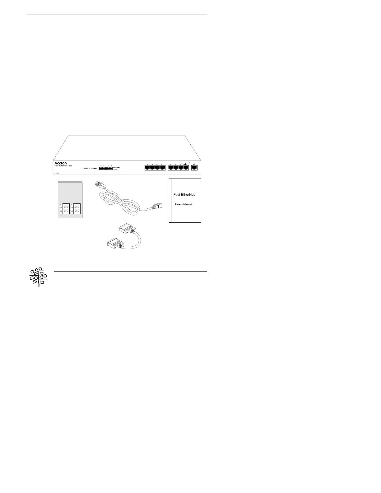
Package Contents
Check your package contents for the following parts:
æ 8/12 port 100BASE-TX Fast Ethernet Stackable Hub
(Fast EtherHub-8se or Fast EtherHub-12se)
æ Power Cord
æ Stackable Cable (D-Sub 25 pins)
æ Rack-mount Kit
æ User’s Manual
If any of these pieces are missing or are damaged, please contact your
dealer immediately.
3
Page 6
Fast EtherHub Installation Manual
Hardware Description
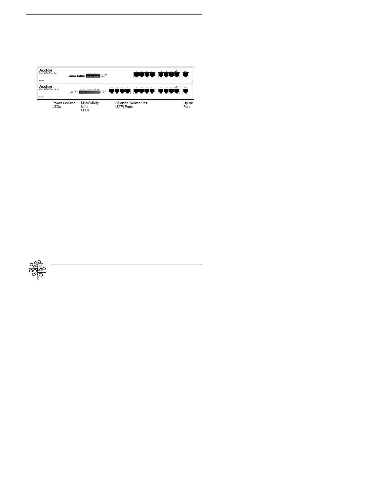
The Front Panel
The front panel contains the 8/12 Shielded Twisted-Pair (STP) ports,
one uplink port, and LED indicators.
Shielded Twisted- Pair (STP) ports
Use any one of the STP ports for connection to a 100BASE-TX node
using Category 5 UTP cabling. Each of these ports provides 100Mbps
bandwidth for connection to a workstation or server.
UPLINK port
The uplink port provides cascading capabilities to a second
100BASE-TX Fast Ethernet hub (if the hub is not stacked).
4
Page 7
Fast EtherHub Installation Manual
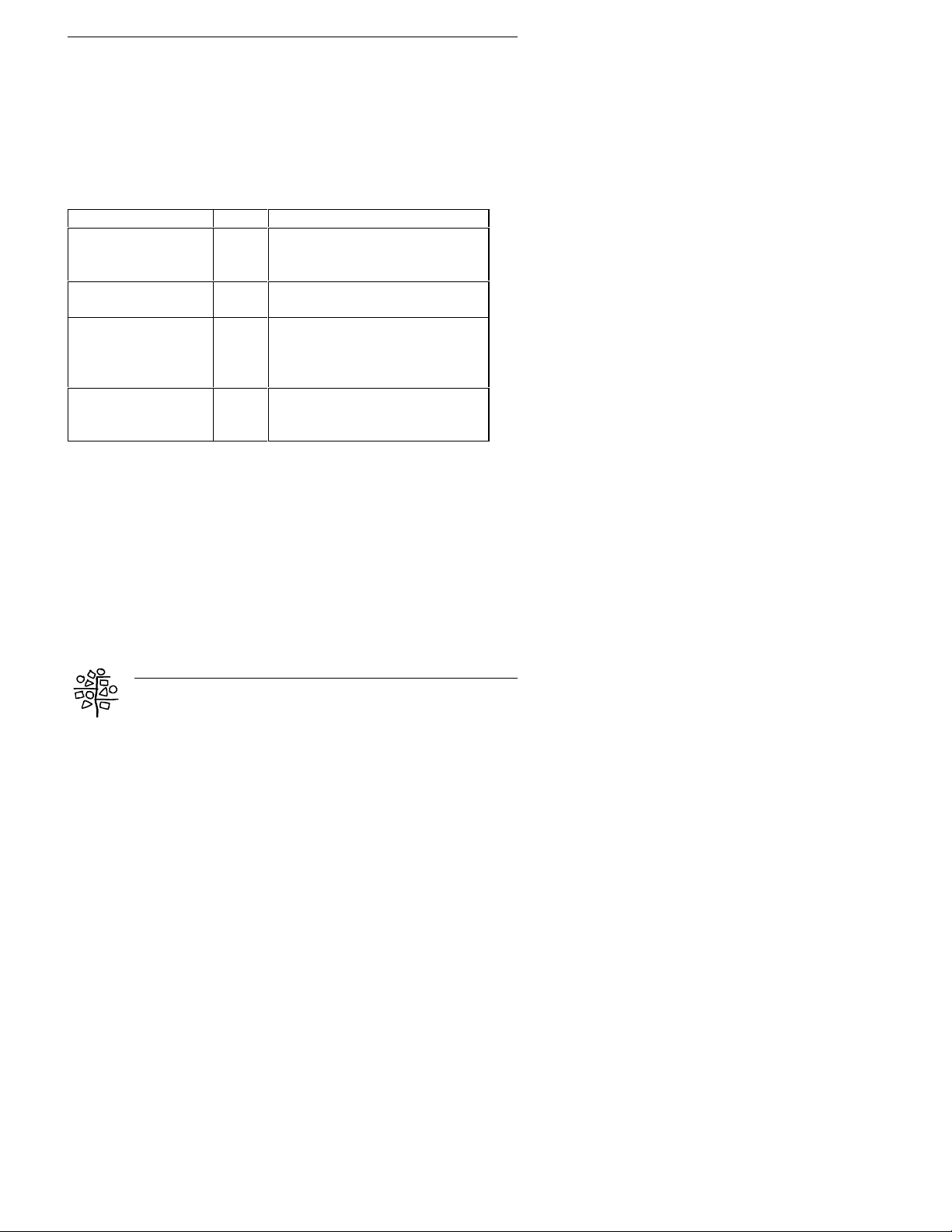
LED indicators
The front panel LED indicators help you monitor the status of each port
and connected segments. There are 4 different LEDs on the front panel;
including power (PWR), collision (COL), LINK/ACTIVITY and ERROR.
This table lists the LEDs a nd their respec tive functions.
LED Function Color Description
Power (PWR) Green Lit: Power On
Unlit: Power Off
Collision (COL) Amber Lit: Data collision occurred
LINK/ACTIVITY Green Lit: Indicates the adapter is
connected to the hub
Blinking: Receiving data
ERROR Yellow Flashing: Data jabber or error
Lit: Indicates partition and
isolation of port
5
Page 8

Fast EtherHub Installation Manual
The Rear Panel
The rear panel of the hub contains the power socket , 2 D-Sub
connectors (25 pins) and air fans.
ower Socket
P
The power socket accepts AC power of 100 - 240V at 50 - 60 Hz.
6
Page 9

Fast EtherHub Installation Manual
HARDWARE INSTALLATION
Quick Installation Procedure
1. Place the hub on a smooth surface or mount it on a rack.
2. Connect power cord to hub and
plug in.
3. Connect workstations to hub
using Category 5 UTP cabling.
? Plug an RJ-45 connector into any port on the hu b ( other than
the Uplink port), and plug the other end into the RJ-45 port on the
workstation’s Fast Ethernet card. Distance between the hub and
the workstation can be no more than 100 meters.
4. Connect each device (up to 8/12) on your network using the process
described in Step 3.
? Make sure you have the correct wiring
To reliably operate your network at 100Mbps, you mus t use
Unshielded T wisted-Pair (U TP) Category 5, or better, Data Grade wire.
While Category 3 or 4 wire may initially seem to work, it will soon
cause data loss.
7
Page 10
Fast EtherHub Installation Manual
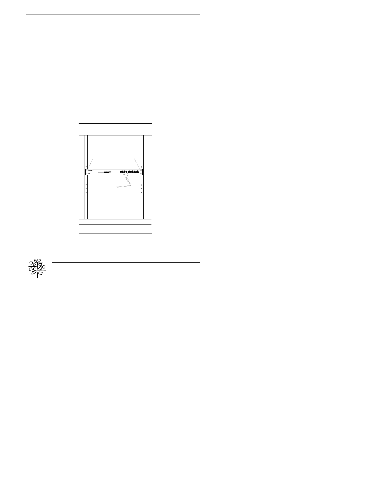
Select an Appropriate Location
A good location is at or near the center of all the computers you want to
link, close to the trunk segment and the other devices you wa nt to
connect, and near a convenient power outlet.
? The cable route should not be near any power lines.
After you have decided on a particular location, you can place the hub
on the top of a table or a shelf, or mount it on a rack.
You may mount the hub on any EIA standard size 19-inch mounting
rack. First attach the supplied mounting brackets onto the sides of the
hub with screws. Afterwards, secure the hub onto the rack by screwing
on the mounting brackets.
8
Page 11

Fast EtherHub Installation Manual
Setting Up 100BASE-TX Stackable Hubs
1. Put the 100BASE-TX stackable hub on the flat surface.
? Ensure the power is off before stacking the hub.
2. Attach the power cord and turn on power to the hub.
3. Connect one end of the D-Sub (25 pins) stack cable to the OUT
port on the first hu b and the other end to the IN port on the next
hub in the stac k.
? Do not connect OUT to OUT or IN to IN port on different hubs.
4. Screw on the D-Sub (25 pins) connectors if necessary.
5. Repeat steps 2-3 until all hubs are combined together in the stack.
You should have a simple chain starting at the OUT port on the
first hub, and ending at the IN on the last hub. You can stack up
to 4 hubs in this manner. Note that a stack acts as a single repeater
set.
?The hub’s backplane ports allow cascading only up to 4 hubs.
9
Page 12

Fast EtherHub Installation Manual
CONFIGURATION
Standard-Alone
The configuration of a simple stand-alone hub is illustrated as below.
The maximum distance between the hub and the workstation is 100
meters.
10
Page 13
Fast EtherHub Installation Manual
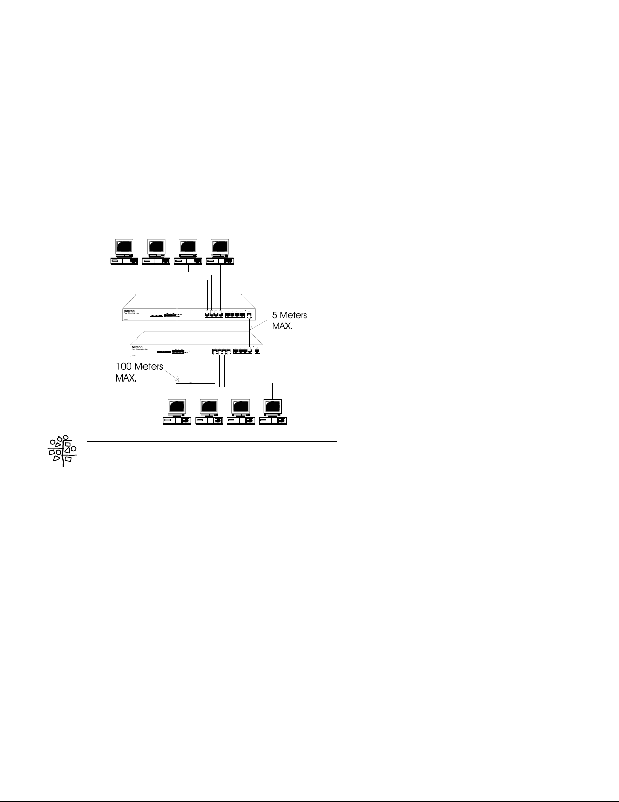
Uplink Multiple Hubs
If you want to connect more than 8/12 ports, you can use the uplink
port to connect to another hub. In compliance with the IEEE802.3u
Class II specification, two repeaters can be cascaded using 5 meters of
cable in a single collision domain.
1. Connect a Category 5 UTP cable to the UPLINK port (Port 8/12)
on the first hub.
2. Connect the other end of the UTP cable to any of Ports 1 - 8/12 on
the second hub (i.e., do not connect it to the UPLINK port on the
second hub).
? You do not need crossover cable if you use the uplink port.
? Do not connect the upl ink port (Port 8/12) on first hub to the
uplink port (Port 8/12) on the second hub.
11
Page 14

Fast EtherHub Installation Manual
Stacking Multiple Hubs
The 100BASE-TX stackable hub comes with stackable backplane port
for cascading up to 4 hubs. As your network grows, this stackable
feature allows you to add additional units for expansion. Depending on
the models used, you will be able to stack up to 32/48 ports. Note the
hubs follow Class I repeater standards when stacked.
12
Page 15

Fast EtherHub Installation Manual
TROUBLESHOOTING
This chapter contains information to help you solve problems. If these
hubs are not functioning properly, make sure they were set up
according to instructions in this manual.
If the hubs don’t connect to the network:
➊ Check the LINK/ACTIV IT Y LED lights on the front panel.
If the LINK/ACTIVITY LED isn
adapter and the hub. Make sure the adapter drivers are loaded .
➋ Try another port on the hub.
➌ Make sure the cable is installed properly.
The network cable must be securely atta ched at all connecti on points. If
the cable is prop er ly attached but the pro blem persists, try a different
cable.
t lit, check all connections at the
❹ Turn off the unit
s power, wait a few seconds, and turn it back on.
13
Page 16

Fast EtherHub Installation Manual
Other Important Tips
➀ Make sure no more than 100 meters of cable are used between the
hub and the desktop.
➁ Verify that the cabling type used is correct. (Category 5 UTP cable)
➂ Make sure the network adapter cards installed in the workstations
and cable connections are in good working condition.
➃ Hubs connected via the backplane ports cannot be cascaded via the
uplink port. When cascading hubs, limit the cascade to two hubs, and
limit the interhub cabling to 5 meters. In a two-repeater topology, the
maximum network diameter between end nodes is 205 meters.
14
Page 17

Fast EtherHub Installation Manual
IEEE802.3u, 100BASE-TX Class I and II repeater
PRODUCT SPECIFICATIONS
Standard
100BASE-TX UTP ports 8/12
Uplink port Hub port # 8/12
Cable Distance 5 meters for repeater to repeater
100 meters for repeater to station
Cabling STP/UTP Category 5 wiring, 100-ohm impedance
Expandability 32/48 ports in class I stackable mode
LED indications Power (PWR) - Green
Collision (COL) - Amber
8/12 Partition LEDs - Yellow
8/12 Link/Activity LEDs - Green
Operating Temperature 0° - 55°C
Operating Humidity 5% - 95%
Power Consumption 2.3A max at 100VAC, 0.95A at 240VAC
Dimensions 435 x 210 x 42 mm
15
Page 18

Fast EtherHub Installation Manual
EMI Warning
FCC Class A Certification
This device complies with Part 15 of the FCC Rules. Operation is
subject to the following conditions:
1. This device may not cause harmful interference, and
2. This device must accept an y i nterference received, including
interference that may cause undesired operation.
Warning: This equipment generates, uses, and can radiate radio
frequency energy and, if not installed and used in accordance with the
instruction manual, may cause interference to radio communications.
It has been tested and found to comply with the limits for a Class A
digital device pursuant to Subpart B of Part 15 of FCC Rules, which
are designed to provide reasonable protection against such interference
when operated in a commercial environment. Operation of this
equipment in a residential area is likely to cause interference, in which
case the user, at his own expense, will be required to take whatever
measures are required to correct the interference.
You may use 100Ω Category 5 unshielded twisted-pair (UTP) or 100Ω
Category 5 shielded twisted-pair (STP) cable for RJ-45 connections.
Warnings
1. Wear an anti-static wrist strap or take other suitable measures to prevent
electrostatic discharge whenever handling this equi pm ent.
2. When connecting this hub to a power outlet, connect the field ground lead on the tripole power plug to a valid earth ground line to prevent electrical hazards.
3. The c onnectors are not for telephone system use.
Note:
In order to maintain compliance with the limits of a Class A digital device,
Accton requires that you use a quality interface cable when connecting to this
device. Changes or modifications not expressly approved by Accton could
void the user’s authority to operate this equipment. Suggested cable type is:
Twisted-pair for RJ-45 connections: 100BASE-TX
16
Page 19

Fast EtherHub Installation Manual
CE Mark Declaration of Conformance
This is to certify that this product complies with ISO/IEC Guide 22 and
EN45014. It conforms to the following specifications:
EMC: EN55022(1988)/CISPR-22(1985) class B
EN60555-2(1987) class A
IEC 1000-4-2(1995)/IEC801-2(1991) 4kV CD, 8kV AD
IEC 1000-4-3(1995)/IEC801-3(1984) 3V/m
IEC 1000-4-4(1995)/IE8C01-4(1988) 1kV - (power line)
0.5kV - (signal line)
This product complies with the requirements of the Low Voltage
Directive 73/23/EEC and the EMC Directive 89/336/EEC.
Safety Compliance
Underwriters Laboratories Compliance Statement
Important! Before making connections, make sure you have the correct
Cord Set. Check it (read the label on the cable) again st the following
specification list.
Operating
Voltage
120 Volts UL Listed/CSA Certified Cord Set
Minimum 18 AWG
Type SVT or SJT three conductor cord
Maximum length of 15 feet
Parallel blade, grounding t ype attachment plug rated 15 A, 125V
Cord Set Specifications
The unit automatically matches the connected input voltage. Therefore,
no additional adjustments are necessary when connecting it to any
input voltage within the range marked on the rear panel.
Do not plug a phone jack connector into any of the RJ-45 ports.
This may damage the hub.
17
Page 20

Warranty
Accton warrants to the original owner that the product delivered in this package will be
free from defects in material and workmanship for the lifetime of the product. For the
warranty to apply, you must register your purchase by returning the registration card
indicating the date of purchase and including proof of purchase. There will be a minimal
charge to replace consumable components, such as fuses, power transformers, and
mechanical cooling devices. The warranty does not cover th e product if it is damaged in
the process of being installed. Accton recommends that you have the company from
whom you purchased this product install it.
THE ABOVE WARRANTY IS IN LIEU OF ANY OTHER WARRANTY, WHETHER
EXPRESS, IMPLIED OR STATUTORY, INCLUDING BUT NOT LIMITED TO ANY
WARRANTY OF MERCHANTABILITY, FITNESS FOR A PARTICULAR PURPOSE, OR
ANY WARRANTY ARISING OUT OF ANY PROPOSAL, SPECIFICATION OR SAMPLE.
ACCTON SHALL NOT BE LIABLE FOR INCIDENTAL OR CONSEQUENTIAL DAMAGES.
ACCTON NEITHER ASSUMES NOR AUTHORIZES ANY PERSON TO ASSUME FOR IT
ANY OTHER LIABILITY.
Copyright
Copyright 1997 by Accton Technology Corporation. All rights reserved. Product
specificat ion are subject to change without notice. All trademarks or brand names are
properties of their respective compani es.
Disclaimer
The publisher assumes no responsibility for errors that may appear in this
document, nor does it make any commitment to update information it contains.
All brand and product names mentioned are trademarks or registered
trademarks of their respective companies.
For warranty information:
Accton Technology Corporation, International Headquarters
No. 1, Creation Rd. III, Science-based Industrial Park, Hsinchu 300, Taiwan, R.O.C.
Phone: 886-3-5770-270 Fax: 886-3-5770-267 BBS: 886- 3-5770-654
18
Page 21

EH3008C
EH3012C
E0797-R01
 Loading...