

Page 1
BSG12aw
BSG12aw
Quick Installation Guide
You can download all documents referenced in this Quick Installation Guide
at www.nortel.com
Tools and materials
Before you install the Business Services Gateway (BSG), ensure
1
that you have the following package contents and materials:
Package Contents
● BSG unit
● power supply and power cord
● two omni-directional antennas
● console cable assembly
● Quick Installation Guide
● four self-adhesive rubber feet
● Regulatory sheet
● Hazardous Substance table
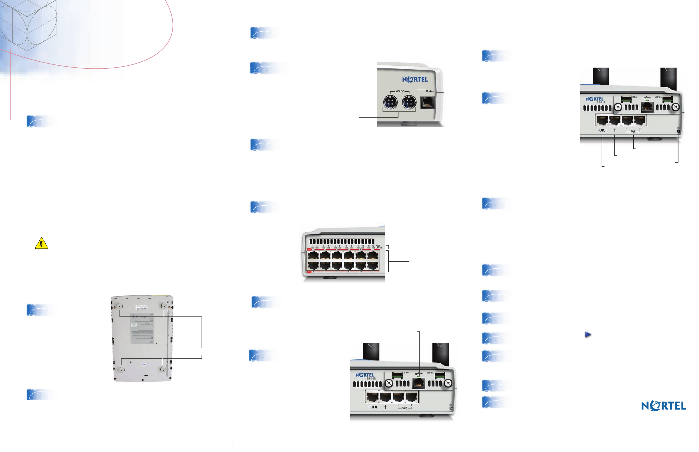
Install the power supply next to the BSG. The power supply must
4
5
6
be within 1.5 m (5 ft) of the BSG and within 1.5 m (5 ft) of the AC
power outlet (wall outlet or universal power supply).
Connect the 48V DC 4-pin DIN
power supply connector into
either of the power outlets at
the back of your BSG.
Two power outlets
Connect one end of the AC power cord into the AC power supply.
Plug the other end of the AC power cord into the AC power outlet
(wall outlet or universal power supply). The System LED on the front
panel lights up.
Connecting LAN devices (VoIP phones
and PCs)
Optional installations
Connecting wireless
Attach the omni-directional antennas to the wireless LAN antenna
10
Connecting analog
or fax devices
11
Connecting the Public Switched
Telephone Network
connectors on the back of the BSG.
Plug one end of an RJ-11
telephone cable into
either of the FXS analog
telephone (RJ-11) ports
on the front of the BSG.
Plug the other end of the
cable into the analog
device.
Console port
FXS ports
FXO port
System LED
Additional Required Materials (not included)
●RJ-11 telephony cable (WAN connection)
●two to three additional RJ-11 telephony cables
(if using analog devices)
● RJ-11 splitter (if only one analog line is available)
Caution: Risk of equipment damage
To avoid damaging the equipment, you must connect the BSG to
an outlet with a third-wire ground. Use the BSG with only the
supplied BSG power supply and a three-wire power outlet.
Installing the BSG unit
For optional methods to install your BSG, see the BSG8ew and
BSG12ew/aw/tw 1.0 Installation Guide (NN47928-302).
Attach the four
2
3
self-adhesive
rubber feet to the
bottom of the BSG
by peeling off the
paper backing and
placing the feet on
the unit.
Position the BSG on a desktop. Make sure you leave enough
space around the unit for ventilation and access to the cables.
Attach feet here
Plug one end of a standard Ethernet cable into one of the twelve
7
8
LAN ports on the front of your BSG. Plug the other end of the
Ethernet cable into your LAN device, such as a VoIP phone or PC.
Ensure that the corresponding LAN port PoE/Link/Act LED lights
up. The corresponding LED will come on only if the device
connecting to that port is powered on.
Connecting the WAN
Plug one end of an RJ-11
9
telephone cable into the
ADSL port on the front of
the BSG. Plug the other
end of the cable into the
telephone jack on the
wall.
ADSL port
PoE/Link/Act LEDs
LAN ports
Plug one end of an RJ-11 telephone cable into the FXO analog line
12
(RJ-11) port on the front of the BSG. Plug the other end of the cable
into the telephone jack on the wall.
Configuring the initial system settings
Complete the following steps using the BSG Quick Start Wizard. Before you start,
contact your Internet service provider (ISP) to obtain your user name, password,
and encapsulation type information (Ethernet, PPPoE).
From a PC connected to the LAN, open a new Web browser, type
13
14
http://192.168.1.1 into the address bar, and press Enter to start the
Web user interface.
In the Login window, enter your user name (nnadmin) and password
(PlsChgMe!), and Click Login.
In the navigation pane on the left, click Quick Start Wizard.
15
Click the blue forward button to start the wizard.
16
Enter your ISP name, user name, and password, and confirm your
17
password by entering it again. For more information about additional
settings within the Quick Start Wizard, see the BSG8ew and
BSG12ew/aw/tw 1.0 Configuration Guide (NN47928-500).
Click Next and enter information on each wizard page as required.
18
On the Review Data page, click Continue.
19
Congratulations! You have successfully
configured the Nortel Business Services
Gateway!
Printed in Canada. Copyright © Nortel Networks Limited 2007. All Rights Reserved
N0156580
NN47928-306
Standard 01.01
 Loading...