

Page 1

Virus TI User Manual
Page 2

Copyright 2004-2006 Kemper Digital GmbH. All rights
reserved.
This manual, as well as the software and hardware described
in it, is furnished under license and may be used or copied only
in accordance with the terms of such license. The content of
this manual is furnished for informational use only, is subject to
change without notice and should not construed as a commitment by Kemper Digital GmbH.
Kemper Digital GmbH assumes no responsibility or liability
for any errors or inaccuracies that may appear in this book.
Except as permitted by such license, no part of this publication
may be reproduced, stored in a retrieval system, or transmitted
in any form or by any means, electronic, mechanical, recording, or otherwise without the prior written permission of Kemper Digital GmbH.
Virus is a trademark of Kemper Digital GmbH. All other trademarks contained herein are the property of their respective
owners. All features and specifications subject to change without notice.
For the latest revision of this manual, visit our website:
www.access-music.de
2
Page 3

Table Of Contents
Introduction
WELCOME 8
THE VARIOUS CHAPTERS 8
SAFETY PRECAUTIONS 9
MAINTENANCE 9
THE REAR PANEL 10
ROTATING THE SOCKETS 11
SETTING UP 11
SWITCHING ON AND OFF 12
SELECTING PROGRAMS 12
ABOUT THE MENUS 13
DIFFERENT WAYS OF WORKING 14
ABOUT USB CONNECTION 16
CREATING NEW SOUNDS 17
ABOUT POLYPHONY 17
First Steps
CHEESE FOR STARTERS? 20
THE AMPLIFIER ENVELOPE SECTION 21
THE FILTERS SECTION 24
THE FILTER ENVELOPE SECTION 29
THE OSCILLATORS SECTION 30
THE MIX SECTION 35
THE MODULATORS SECTION 37
THE MATRIX SECTION 39
THE ARP SECTION 40
THE EFFECTS SECTION 41
THE MASTER SECTION 44
HYPERSAW AND WAVETABLE 47
VirusControl
INTRODUCTION 50
3
Page 4

COMPATIBILITY 52
STARTING UP 53
LOADING VIRUSCONTROL 55
EASY PAGE 57
BROWSER PAGE 58
OSC PAGE 63
FILTER PAGE 65
LFO PAGE 67
MATRIX PAGE 68
ARP PAGE 69
FX PAGE 70
COMMON PAGE 71
REMOTE PAGE 72
GENERAL HINTS AND TIPS 74
Sound Parameters Reference
ARP 76
ARPEGGIATOR 76
MATRIX 79
SLOT 79
MODULATORS 81
LFO 1 82
LFO 2 84
LFO 3 84
LFO 1 DESTINATIONS 84
LFO 2 DESTINATIONS 86
LFO 3 DESTINATION 87
EFFECTS (UPPER ROW) 89
DELAY 90
REVERB 91
LOW EQ 93
MID EQ 94
HIGH EQ 94
EFFECTS (LOWER ROW) 95
DISTORTION 95
ANALOG BOOST 96
CHORUS 97
PHASER 98
VOCODER 100
VOCODER TABLE 104
INPUT FOLLOWER 105
INPUT RING MODULATOR 106
OSCILLATORS 107
OSCILLATOR 1 – CLASSIC 110
OSCILLATOR 1 – HYPERSAW 112
OSCILLATOR 1 – WAVETABLE 114
OSCILLATOR 2 – CLASSIC 115
OSCILLATOR 2 – HYPERSAW 117
OSCILLATOR 2 – WAVETABLE 118
OSCILLATOR 3 120
4
Page 5

COMMON 121
SUB OSCILLATOR 123
NOISE 124
RING MODULATOR 124
MASTER 125
COMMON 128
UNISON 131
VELOCITY MAP 132
INPUTS 133
SURROUND 134
CATEGORIES 134
SOFT KNOB 135
STORE 136
STORE 136
MIX 137
FILTERS 139
SATURATION 140
FILTER-1 141
FILTER-2 143
COMMON 144
FILTER ENVELOPE 145
AMP ENVELOPE 146
FILTER ENVELOPE 148
AMPLIFIER ENVELOPE 149
Configuration Reference
RANDOM PG 152
MIDI 152
MIDI DUMP RX 154
MIDI DUMP TX 154
KEYBOARD 155
MIDI CONTROL 157
INPUTS 158
AUDIO CLOCK 159
SOFT KNOB (GLOBAL SETTINGS) 159
KNOB BEHAVIOUR 160
GLOBAL TUNING 160
SYSTEM 161
Multi Mode Reference
PATCH 166
Appendix A - Legal Declarations
COMPLIANCE 172
DECLARATION OF CONFORMITY 174
WARRANTY REGULATIONS 175
5
Page 6

Appendix B - Glossary
GLOSSARY 178
Appendix - Patch Names
ROM-A 192
Index
INDEX OF FUNCTIONS ETC. 210
6
Page 7

1: Introduction
Page 8

Welcome
Dear Virus owner
Congratulations on choosing the new Virus TI, the latest generation in a deliberate process of evolution that has kept the
Virus name at the forefront of synthesizer technology for many
years. TI stands for Total Integration, meaning that the hardware can be fully integrated into a PC or Mac-based studio via
the VirusControl
Before switching your Virus TI on, please read this chapter
thoroughly!
™
plug-in (VSTi or Apple Audio Unit).
The Various Chapters
This manual is structured as follows:
> Introduction: What you are reading now. Fundamental infor-
mation you should know before trying out your Virus.
> First Steps: A practical guide for beginners, intermediates
and experts alike. The best starting point before delving into
the reference chapters.
> Sound Parameters Reference: The main body of this man-
ual. Every parameter concerning sound generation and
treatment is listed here, with brief explanations and crossreferences.
> Configuration Reference: All global settings – parameters
used to adapt the Virus to suit your way of working.
> Multi Mode Reference: A list of the Multi Mode parame-
ters, with brief explanations.
> VirusControl: Introduction to the VirusControl application.
> Appendices: Legal matters, charts, diagrams, glossary.
>Index: Where to look when you are not sure where to look!
8
Page 9

Safety Precautions
Please read the following carefully. Some of this advice concerns your health as well as that of your instrument!
Avoid exposing your Virus to moisture, dust or dirt. Do not place
open liquids (e.g. coffee cups) anywhere near the unit. If any
substances get into the Virus housing, you should switch it off,
disconnect the power supply and contact a qualified service
techician.
Avoid exposing the unit to excessive heat or direct sunlight.
Especially when rack-mounting your Virus (desktop version),
please ensure that relatively cool air can circulate freely around
the unit.
Avoid exposing the unit to physical shock or vibrations. Make
sure it is placed firmly on a flat surface or properly secured in a
rack.
If your Virus model requires a 12V DC external power supply,
only use the one that was included with the unit. Never connect
the Virus to a power outlet that does not fully comply with
national safety regulations. Never use an external power supply
which wasn’t designed to match the local voltage requirements.
Disconnect the power whenever you are unlikely to use the
Virus for a long period of time. Always pull on the plug itself, not
on the cord. Never touch the mains plug with wet hands.
The Virus is capable of generating levels that can cause irre-
versible damage to your ears, either via an external amplifier or
when using headphones connected directly to the unit. Please
keep levels reasonable at all times! Make sure that the equipment you connect the Virus TI to matches the Virus’
requiremtents (+4dB Outputs etc.)
Maintenance
Updating the OS
Access Music is famous for improving their products via free
updates to the operating system. We recommend that you visit
www.access-music.de regularly and download the latest OS.
Cleaning
Only use a soft, dry cloth or soft brush to clean the panel – do
not apply any liquids. Note that industrial or household solvents
can cause severe damage to surfaces.
Repair
Never open the Virus yourself – there are no user-servicable
parts inside. If your Virus ever needs repairing, please contact a
qualified service technician.
9
Page 10

Replacing the Battery
To prevent your sounds from being lost whenever you switch
off the power, there is a battery inside your Virus. This may
need replacing after 4 or 5 years by a qualified service technician. Remember to backup your data beforehand!
The Rear Panel
Sockets
>USB: Audio and MIDI communication with computers.
Disposal
Disposal of old Electronical & Electronic equipment (Applicable
throughout the European Union and other European countries
with seperate collection program).
The marking shown on the product indicates that it should not
be disposed with other household waste. Please take your
Virus TI to an applicable collection point for recycling of electronical and electronic items.
For further questions on an ecological friendly disposal of this
product, please contact your Access dealer respectively your
local government office.
> MIDI IN / OUT / THRU: The usual trio
>S/PDIF: Digital audio I/O
> INPUT: Audio input jacks
>OUTPUT 1: Main audio output jacks
>OUTPUT 2 / 3: Additional audio output jacks
> 12V DC IN (desktop model): Power supply input socket.
> HEADPHONES: Stereo audio output jack.
10
Page 11

Rotating the sockets
The sockets on the rear panel of the Virus TI desktop model can
be rotated 90° so that the unit can be mounted in a 19” rack
without requiring free space above the “back” panel. Many
owners will consider themselves skilled enough to attempt the
following themselves – although this should ideally be done by a
professional technician. We recommend to contact your Access
dealer for further assistance.
Important notice: Kemper Digital GmbH takes no responsibility
whatsoever for any damage incurred while attempting to carry
out these instructions! Rotating the sockets does not void the
warranty of a Virus TI Desktop.
What you will need: A flat and soft working surface (e.g. your
couch), a bowl or similar for the screws, a suitable crosspoint
screwdriver and hexagonal key.
Remove any attached cables and turn the unit upside down.
Remove the end-cheeks using the hexagonal key.
Using a small cross-point screwdriver, remove the 6 screws in
the baseplate. Carefully remove the baseplate and set it aside
for the moment. Remove the 6 screws between the rear-panel
sockets.
Pull up the “sockets unit” a little and perch it on the ledge of the
back panel. Using both hands, carefully pull the 40-way con-
nector from its socket on the motherboard. The sockets unit is
now free.
Using the latest set of screws (i.e. the ones without pointed
ends), attach the sockets unit firmly into the baseplate, which
has all the necessary holes.
Position the baseplate (with the sockets now firmly in place) so
that the 40-way cable can reach the socket on the motherboard. Carefully but firmly plug it all the way in.
“Close the lid” and use the remaining 6 small screws to reattach
the baseplate. Turn the unit “right side up” and attach the power
cable to ensure that the 40-way plug has been properly fitted.
Setting Up
The following steps include several important precautions. In
addition to the simple setup described here, the Virus TI can be
connected in a variety of ways to suit virtually any audio environment.
Please do not plug the Virus into the mains power yet. First of
all, temporarily switch off any devices you will eventually be
connecting your Virus to, and turn all main volume controls
(mixer, amplifier) down to minimum.
If your Virus is a desktop version, connect the MIDI OUT from a
keyboard or sequencer to the MIDI IN socket on the Virus.
11
Page 12

Connect both the OUTPUT 1 sockets (standard mono jacks) to
two line inputs on your stereo amplifier or audio mixer. Make
sure to only use qualified amplifiers. Check back with your
local Access dealer for further details. When using two separate mixer channels, pan them to the extreme left and right
respectively. If you prefer to use headphones, use the HEADPHONES socket on the rear panel.
Connect your Virus to the mains power. Press both TRANS-
POSE buttons at the same time to “wake up” the Virus. Switch
the rest of your equipment on in the following order: the MIDI
send device (keyboard or sequencer etc.), then the mixer and
finally the amplifier.
Set up the MIDI send device (keyboard or sequencer) so that it
sends on MIDI channel 1 (for now).
Turn up the MASTER VOLUME on your Virus to maximum and,
while playing some notes, adjust the volume controls on your
mixer/amplifier to a reasonable listening level. If you are using
a mixer, you might find some useful advice on setting optimum
levels in the mixer´s own documentation.
Switching On and Off
Virus TI models do not have a physical on/off switch. To put
the unit into standby mode, press and hold both TRANSPOSE
buttons until the countdown reaches zero. Press the same buttons to “wake up” the Virus again.
Selecting Programs
Your Virus TI has 20 banks of memory (RAM-A to RAM-D,
ROM-A to ROM-P), each containing 128 SINGLE programs
numbered from 0 to 127. A total of 2560 sounds...
To try out some sounds, make sure you are in SINGLE mode
and that no menu is open – you might have to press the
SINGLE button (in the Master section to the right of the display) first. There are three basic methods of selection:
Sequentially
The most obvious way to select programs is by stepping
through them using the BANK and PROGRAM buttons to the
right of the display. When any menu is open, these buttons are
used for PARAMETERS and VALUE instead – see “About the
Menus” below. To scroll automatically, hold one of them down
for a while.
A quick method of reaching any program within the current
Bank: Hold down SHIFT and turn the VALUE 3 knob.
12
Page 13

By Category
Because there are so many sounds to choose from, programs
can be assigned one or two so-called “Categories”. This information is stored within each program. A practical demonstration:
Press the SEARCH button to the left of the display and use the
VALUE 1 knob to change the category to “Drums”. Then use the
VALUE +/- buttons to browse through programs – in the bar at
the top of the screen you will see programs that are in the
“Drums” category only. When you have found a suitable program, press the
ÛEXIT button.
About the Menus
How to open menus
The main menus are opened via the EDIT buttons you will find in
most of the sections. The usual method is to SELECT an element first (e.g. LFO1, OSC 2 or REVERB) then press the EDIT
button in that same section.
All buttons in the MATRIX section as well as CONFIG in the
Master section also open menus.
Via MIDI
All MIDI sequencers and professional MIDI keyboards are capable of transmitting Bank and Program change messages via
MIDI.
How to make full use of Edit Buttons
If pressed repeatedly, the EDIT buttons in the FILTERS and
MASTER sections will step through the menu pages. Those in
the OSCILLATORS and lower EFFECTS sections toggle
between the selectable (element-specific) pages and additional,
non-selectable parameters e.g. the Vocoder. Similarly, the one
in the MODULATORS section toggles between the selected
LFO’s main settings and its Destinations menu.
How to navigate within menus
Many menus in your Virus require more than one page. These
can be found by using the PARAMETERS buttons (in the Master
section, to the right of the display).
13
Page 14

If a menu is already open, selecting a different element within
the same section (e.g. LFO3 instead of LFO1, OSC1 instead of
OSC2 or LOW EQ instead of REVERB) will jump to the new
menu.
How to change values within menus
Use the VALUE knobs below the display. Whenever you enter
a menu page, one of the parameters will already be active
(indicated by a triangular cursor). Its value can be decremented/incremented via the VALUE buttons. To move the cursor without changing values, hold down SHIFT and press one
of the PARAMETERS buttons.
There is actually a system parameter which governs how the
PARAMETERS buttons work – see “Navigation” on page 163.
How to close menus
To exit any menu, press the ÛEXIT button to the left of the display. It is not necessary to press
menu. Re-selecting the current basic mode (SINGLE, MULTI)
will also exit menus.
ÛEXIT before opening a new
Different Ways of Working
Single mode
This is the standard mode for playing just one sound at a time.
The next chapter is a simple but detailed tutorial to help you
become familiar with Single mode operation.
Multi mode
Your Virus can play 16 different sounds at the same time:
MULTI programs contain 16 PARTS, each equivalent to a
SINGLE program plus a few additional parameters such as
MIDI channel, fine tuning, key range etc..
Unlike earlier Virus models and many other synthesizers,
MULTI programs in the Virus TI do not simply reference individual sounds, but actually contain the data, including all
effects. Multi mode is therefore predestined for more complex
programs.
Whenever the Bank or Patch parameters (see “Patch” on
page 166) are changed, the corresponding Single program is
copied into the current Part of the Multi program. For details
about Multi mode parameters, see the “Multi Mode Reference”
on page 165.
14
Page 15

Sequencer mode
Whereas Multi mode offers maximum flexibility for layering
sounds, defining keyboard splits etc., Sequencer Mode is usually the better choice for multitrack MIDI sequencing purposes.
Press the MULTI and SINGLE buttons at the same time (or start
the VirusControl application – see below). Sequencer Mode
accesses an area of memory containing 16 Single programs. It
couldn’t be simpler: the MIDI channel is always the same as the
PART number (1 to 16).
Remote mode
The Virus TI can be used as a MIDI controller i.e. the controls
can be configured to suit a variety of MIDI devices. There are
several Remote setups suitable for popular devices already
included in your unit. Remote mode is accessed by holding
down SHIFT and pressing the CONFIG button to the left of the
display. User-defined remote setups can be created using
VirusControl...
VirusControl
The VirusControl application (for PC or Mac) makes the Virus TI
appear to be a multi-channel VST/AU soft-synth within any suitable host program e.g. Logic, Cubase etc.. Virus TI is the
world’s first hardware synthesizer featuring sample-accurate
timing and delay-compensated audio/MIDI. See “VirusControl”
on page 145 for details on setting up, compatibility and how to
work with this revolutionary feature.
15
Page 16

About USB Connection
Don’t use a hub! To achieve the level of performance and integration the Virus TI series provides, you must reserve a USB
slot exclusively for the Virus TI i.e. this specific port should not
be shared with any other USB device. During beta-testing with
various PC and Mac setups, we found that using certain USB
hubs not only slowed down the connection speed but often
made the entire connection unreliable. For this reason, we
eventually decided not to support the use of USB hubs at all.
Note: Virus Control constantly checks the MIDI and AUDIO
connections and displays an alert message if it sees any problems.
A Typical Setup
Changing knob response
A global parameter (see “Response” on page 160) affects how
most of the knobs on your Virus react, and the current value of
this parameter may not suit your needs...
16
Page 17

Press the CONFIG button to the left of the display and use the
PARAMETERS buttons to scroll through the pages until you
reach the one shown above. Using the VALUE 1 knob, change
Response to “Jump” if this is not already selected. Press the
ÛEXIT button to return to normal operation. Later on, you may
prefer one of the other options (Snap or Rel) to prevent glitches
during live performance.
Note that some knobs will have no audible effect because they
depend on other parameters e.g. the RATE of an LFO that isn’t
being used, or the DECAY of an envelope when SUSTAIN is at
maximum etc..
Creating New Sounds
The INIT Programs
The end of bank ROM-A has been reserved for a few simple
templates, which you can use whenever you want to create
sounds “from scratch”. For instance, the instructions in the next
chapter will often ask you to select one of those.
About Polyphony
The average number of voices the TI series (with its two DSPs)
can deliver is quoted at about 80, with a maximum of more than
100. However, to reach such giddy heights, the TI makes very
dynamic use of resources i.e. using certain features can lower
polyphony to well below these figures. For instance, doubling
the number of Unison voices e.g. from 3 to 6 will reduce
polyphony by half.
If you ever find you need to maximize polyphony (e.g. in Multi
mode), try minimizing your use of the following “prime suspects” first: Unison mode, Reverb, Analog Filter models and
Oscillator 3.
17
Page 18

18
Page 19

2: First Steps
This hands-on tutorial introduces every physical control on the panel, as well as a few important parameters in the menus.
Page 20

Cheese for Starters?
If your Virus TI is a desktop model, you should have a MIDI keyboard connected...
The most effective way of getting to know your Virus is by performing very simple exercises “hands-on”, and that’s why
many of the sounds you will be asked to make are cheesy to
say the least! Despite the risk of compromising your aesthetic
sensibilities or overstating the obvious, I hope you will appreciate the advantages of this method.
Throughout this chapter you will often be asked to “Restore
ROM-A126” or “Restore ROM-A127”. To do this, press the
ÛEXIT button (closes any open menu), then use the VALUE
buttons to step to the neighbouring program then back again.
Make sure you are in SINGLE mode, then select program
ROM-A127 (i.e. Bank ROM-A, program number 127). Play a
note on your keyboard. Like an organ, the sound starts
abruptly, sustains as long as you hold down the key, then
stops abruptly. Unlike an organ, you can change this behaviour
by adjusting a few “envelope” parameters...
20
Page 21

The Amplifier Envelope Section
The four knobs at the bottom right of the panel control the
amplifier envelope i.e. how volume changes during and immediately after each note you play:
ATTACK
Turn the ATTACK knob down to minimum to reach the value
already stored in ROM-A127 (which is 0). Now turn it up slowly
while repeatedly playing notes on your keyboard – you will hear
the start of each note becoming progressively slower. Leave
ATTACK at around 40 for now.
>ATTACK: How long it takes for the level to go from silence to
maximum.
>DECAY: How long it takes from maximum to the SUSTAIN
level...
> SUSTAIN: The level of sustained notes immediately after
DECAY.
>RELEASE: How long it takes to fade out after notes are
released.
Here are a few practical experiments for novices.
!-0,)&)%2%.6%,/0%
!44!#+ $%#!9 3534!). 2%,%!3%
3534!).3,/0%0!4#(6/,5-% 4%-0/
DECAY
Turn the DECAY knob up to maximum. The original value was
already 127 – you should see the white “original value indicator”
LED in the MIX section light up. Slowly turn DECAY down while
repeatedly playing a note on your keyboard. You will hear the
note getting shorter until it becomes a very short blip when
DECAY reaches minimum. Leave DECAY at minimum for now.
SUSTAIN
Turn the SUSTAIN knob down to minimum (the original value
was already 0). Now turn it up again while repeatedly playing a
note on your keyboard. The original value indicator should disappear, and you should hear the volume of the sustained note
change accordingly. Leave SUSTAIN at 64 and take DECAY
back up to around 40.
21 FIRST STEPS
Page 22

RELEASE
,
-
6
/
ÌiÊ"vv ÌiÊ"
Turn the RELEASE down to minimum (the original value is 4).
Then, while playing notes on your keyboard, gradually turn it
up again: The sound fades more slowly after you release keys.
Set RELEASE to around 40 – the amplifier envelope now looks
something like this:
PATCH VOLUME
Via SHIFT + ATTACK. The overall volume, stored as part of
each program. Mainly used for balancing levels between different programs. The best value to start with is 100, leaving you
some headroom to make this particular program louder in
future.
6
SUSTAIN SLOPE
Via SHIFT + SUSTAIN. If SUSTAIN SLOPE is set to any value
other than 0, the sustain phase (which is normally flat) turns
into a gradient:
-
,
ÌiÊ"vv ÌiÊ"
/
All the red labelling (blue in the case of the Pølar model) you
can see on the panel identifies the SHIFT functions. To access
these, hold down the SHIFT button to the left of the display
immediately before using the knob or button, then release it
afterwards.
22
Page 23

Take SUSTAIN SLOPE down to -32. Negative values cause the
sustain phase to fall (eventually reaching silence – you can
check this by playing a relatively long note on your keyboard).
So what do positive SUSTAIN SLOPE values do to an envelope? The sustain phase rises, eventually reaching maximum if
you don’t release the note beforehand. Set SUSTAIN SLOPE to
+32 and play a long note.
6
-
,
ÌiÊ"vv ÌiÊ"
/
All these envelope “times” (Attack, Decay and Release), as well
as what appears to be a gradient (Sustain Slope), are actually
rates. This technicality can be safely ignored in practice.
TEMPO
Via SHIFT + RELEASE (in the AMP ENVELOPE section). The
Virus has a master clock to which the arpeggiator is always synchronized. LFOs and delay effects can also be synchronized to
this clock.
Locate the program ROM-A 26 “Dr.What?HS”, switch on arpeggio HOLD (via SHIFT + ARP ON), and play a note on your keyboard. You can see the LFO1 indicator blinking in time with the
arpeggio because, in this particular program, it is synchronized
to the clock. Now experiment with TEMPO (SHIFT + RELEASE
in the AMPLIFIER ENVELOPE section). Did you notice how
smoothly the delay effect catches up with any tempo changes
you make?
TEMPO has a range of 63 to 190 bpm. However, the master
clock automatically slaves to any incoming MIDI clock data
(including rates which are beyond these limits). In this case, the
TEMPO parameter is simply ignored.
23 FIRST STEPS
Page 24

The Filters Section
In comparison with “Dr.What?”, the few sounds you have been
asked to create so far have been primitive and harsh. In subtractive synthesizers such as the Virus, the tonal quality of the
oscillators can be radically altered by sending them through filters.
There are two main filters in your Virus, but before learning how
to access them individually, let’s start by experimenting with
the three parameters you will find on any subtractive synthesizer: CUTOFF, RESONANCE and ENV AMOUNT (as it is
called in the Virus):
&),4%23
#54/&& 3%,%#4-/$%&),4 &),4%$)4
2%3/.!.#% %.6!-/5.4
+%9&/,,/72%3/.!.#%
,0
(0
"0
"3
&),4%2"!,!.#%#54/&&
&),4&),4
CUTOFF
Restore ROM-A127. Vary the CUTOFF while playing notes on
your keyboard. At low values, even medium frequencies are filtered out – the sound is very mellow.
As you turn CUTOFF up, higher frequencies are allowed to
pass through the filters, until the sound becomes brightest at
maximum CUTOFF. This is typical of lowpass (LP) filters, one
of the four basic types available in the Virus.
You have actually been using two lowpass filters in series here
– in ROM-A127 they have been configured to appear as just
one “double-strength” filter – we will come to the responsible
parameter (“Routing”) shortly.
RESONANCE
RESONANCE emphasizes any frequencies close to the cutoff
position. Play a note and sweep CUTOFF as you did just now,
then turn up RESONANCE and try again. At higher
RESONANCE values, the cutoff frequency becomes quite
dominant. You should be able to hear individual harmonics
being picked out if you turn CUTOFF slowly enough. If you like,
go back to program ROM-A 26 and try a lot more
RESONANCE.
24
Page 25

ENV AMOUNT
Controls how much the filter envelope affects cutoff – like automating the CUTOFF knob with each and every note you play.
Here's how to make a very simple analogue bass sound:
Restore ROM-A127 and turn CUTOFF down to minimum. Play
individual notes while adjusting ENV AMOUNT until you hear a
satisfying “plunk” (somewhere around 70), then take the RESONANCE up a little. Locate the TRANSPOSE buttons to the left of
the display, and change the setting to -1 or -2. Play your favourite funky bass riff…
The FILTER ENVELOPE section has the same structure as the
AMPLIFIER ENVELOPE, so you should already know how to
use these knobs effectively to modify your bass sound. Don’t
forget to try SUSTAIN SLOPE (SHIFT + SUSTAIN). You should
try adjusting ENV AMOUNT and RESONANCE again – filter
parameters are highly interactive!
FILTER BALANCE
At -64 you can only hear the output of filter 1. In the central
position (0), both filters contribute equally. At +63 you can only
hear the output of filter 2.
SELECT (FILT 1, FILT 2)
Use these buttons to select which of the filters you would like
the RESONANCE and ENV AMOUNT knobs to control. If you
press both buttons at the same time, the knobs will apply to
both filters simultaneously (as they already do in ROM-A127).
CUTOFF 2
A separate cutoff control for filter 2. This can be either an offset
(i.e. a constant amount below or above filter 1) or an independent value, depending on another parameter in the filter’s EDIT
menu (see “Cutoff Link” on page 145).
MODE (FLT1, FLT2)
Using the FILT1 and FILT2 buttons, you can set each filter to
one of following types:
> LP = Low Pass: Allows frequencies below the cutoff point to
pass through i.e rejects those above the cutoff point
> HP = High Pass: Allows frequencies above the cutoff point to
pass through i.e. rejects those below the cutoff point
> BP = Band Pass: Allows frequencies close to the cutoff point
to pass through i.e. simultaneously rejects those above and
below the cutoff point
25 FIRST STEPS
Page 26

> BS = Band Stop: Rejects frequencies close to the cutoff
point (within a certain “band”) i.e. allows frequencies above
or below the cutoff point to pass through.
Your Virus actually has yet another filter mode which simulates
the classic Minimoog
oscillation). This cannot be selected directly from the panel,
but only from within the filter EDIT menu. If you simply can’t
wait to try it out, bookmark this paragraph and see “Mode” on
page 142.
At this point you should experiment with each filter mode in
isolation i.e. listen to only one of the filters at a time: Restore
ROM-A127, take FILTER BALANCE down to -64 (this isolates
Filter 1), and use the FILT1 button to select another mode. Play
your keyboard while adjusting CUTOFF and RESONANCE.
Repeat until you have become familiar with all four modes.
While experimenting with BS (Band Stop), did you notice how
turning the RESONANCE knob up doesn't actually add resonance, but narrows the band instead? Very subtle...
™
low pass (including it’s typical self-
SHIFT + RESONANCE for on-the-fly adjustments because you
don’t have to check the status of the LEDs above the SELECT
buttons first.
KEY FOLLOW
Via SHIFT + ENV AMOUNT. High notes are generally brighter
than low notes when played on acoustic instruments.
KEY FOLLOW can emulate this effect by making Cutoff follow
the notes you play...
Restore ROM-A127, take CUTOFF down to around 64 and
play the keyboard to get used to the sound of a “flat” filter
across the entire keyboard. Then hold down SHIFT and turn
KEY FOLLOW (i.e. the ENV AMOUNT knob) up to maximum.
Play your keyboard again.
>Into the Filter Menu
RESONANCE 2
Via SHIFT + RESONANCE. Filter 2 resonance only. Although
you can press the SELECT button labelled FILT2, then use the
RESONANCE knob (without SHIFT), it is often faster to use
There are several important parameters in the filter menu, a
few of which have already been mentioned in passing – here
are the ones you should become familiar with first. Press the
EDIT button in the FILTERS section and use the PARAMETER
buttons to find the following page:
26
Page 27

Routing
Here’s that “Routing” parameter mentioned earlier – twist the
VALUE 1 knob to see the various options...
So far you have used the filters either in series (the output of filter 1 is sent to the input of filter 2) or in isolation (by setting
extreme FILTER BALANCE values). Here is a list of all four routing options – you might like to look up the word “Pole” in the
glossary:
> Serial 4: The filters are routed in series, with two poles each
(12dB per octave). This adds up to a total of four poles (i.e.
24dB per octave) if FILTER BALANCE is dead centre (0).
> Serial 6: The filters are routed in series. Filter 1 has four poles
(24dB per octave) and filter 2 has two poles. This adds up to a
total of six poles i.e. 36dB per octave if FILTER BALANCE is
dead centre (+0).
> Parallel 4: The filters are routed in parallel, with two poles
each.
> Split Mode: The filters are also routed in parallel, with two
poles each. Unlike the Parallel 4 mode, each filter processes a
different set of sources: Oscillator 1 and the sub-oscillator are
routed to filter 1, whereas oscillator 2, its FM signal and noise
are routed to filter 2. The ring modulator (see “RING MODULATOR” on page 137) is disabled.
To step through filter routings without having to open the menu,
hold down SHIFT and press the Filter 2 button (labelled FILT2).
Cutoff Link
When set to “Off”, the CUTOFF knobs are independent of each
other. CUTOFF controls filter 1, CUTOFF 2 controls filter 2.
When Cutoff Link is set to “On”, the CUTOFF knob can control
both filters at the same time – CUTOFF 2 becomes an offset i.e.
it determines how much lower or higher filter 2 is than filter 1.
Note that Cutoff Link is normally left on (as it is in most programs, including ROM-A126 and ROM-A127).
About Saturation
The term “Filter Saturation” was originally coined to describe
the effect caused by pushing the input of a filter beyond its natural limits. Jan Hammer’s work on “Birds of Fire” (Mahavishnu
Orchestra) is a classic example but, depending on your age
and/or musical tastes, you might be more familiar with the searing techno “bass lines” and various other distorted synthesizer
sounds used in more recent music.
27 FIRST STEPS
Page 28

In the signal flow, the saturation stage comes immediately after
Filter 1. Therefore if you have added a lot of overtones, you can
still filter them out using filter 2 (assuming the routing is serial see above).
Access have kept the term “Saturation”, but greatly expanded
on the idea – several different Saturation types can be selected
(via SHIFT + OSC VOLUME). Here are a few experiments to get
you started:
Hold down the SHIFT button and turn the OSC VOLUME knob
to see the various SATURATION TYPEs. Select one of the
more drastic types e.g. “Digital”, release the SHIFT button and
experiment with OSC VOLUME (i.e. without using SHIFT). You
might like to filter the results now!
Now let’s try out some of the other saturation types. Turn the
SHAPE knob down to minimum and try out the Wave Shaper
and Rectifier types in turn. Again, you should experiment with
OSC VOLUME because this parameter affects the tone.
The Bit Reducer, Rate Reducer and Rate+Follow types can be
used to emulate the tonal characteristics of early digital synthesizers and samplers. You may not like these at first, but
they can certainly add “grit” to a sound.
Finally, you should try out the four additional saturation types
(which are actually additional filters). High+Follow is especially
useful for thinning out a sound without using filter 1 for this
purpose.
28
Page 29

The Filter Envelope Section
This obviously has the same structure as the amplifier envelope.
Using your knowledge from previous experiments, use all the filter knobs and buttons (plus the Routing parameter in the filter
EDIT menu) to make a new sound from scratch. If you feel the
need to save your work at any point, bookmark this page and
read the information about “Store” on page 136.
&),4%2%.6%,/0%
!44!#+
3534!).3,/0%
2%,%!3%3534!).$%#!9
29 FIRST STEPS
Page 30

The Oscillators Section
This is where the raw sound is generated. There are three main
oscillators but only one set of knobs in the top row, so we'll
start with a very important button – the one that selects which
particular oscillator you want those knobs to control...
SELECT
Restore ROM-A127 and take a look at the row of LEDs above
the SELECT button. OSC1 is currently active, so whatever you
do with the top row of knobs will only affect oscillator 1. There
is actually an exception to this rule (DETUNE 2/3), but we'll get
to that in due course.
/3#),,!4/23
7!6%
3(!0%
-/$%
/3# /3# /3#
7!6%3%,%#407 3%-)4/.%
0!.)#
$%45.%
5.)3/.$%45.%0/24!-%.4/
&-!-/5.4%$)4 39.#3%,%#4 /3#/. -/./
&--/$%
SHAPE
In your experiments so far you have only used one type of
wave – a Sawtooth. Now it’s time to try out some of the other
waveforms:
Restore ROM-A127 and play your keyboard while turning the
SHAPE knob. At minimum you will hear a pure Sine wave, in
the centre a pure Sawtooth, and at maximum a pure Pulse.
Listen to those extremes for a while, then try out different mixtures using the SHAPE knob. You will see the percentage mixture of waveforms being updated whenever you turn the knob.
Again, the Virus TI has much more under the hood than is
immediately apparant: As well as the “Classic” oscillators we
have been using so far, the TI offers two other highly interesting types called “HyperSaw” and “WaveTable”. Please be
patient – you will be trying these out soon enough!
30
Page 31

I only mentioned Sine, Sawtooth and Pulse above. However, the
Sine is only one of 64 waves available in Classic mode, and the
Pulse can change it’s “width”. The very clever knob labelled
WAVE SELECT/ PW controls both of these parameters, but not
at the same time...
WAVE SELECT/ PW
Turn SHAPE down to minimum (the display should read “Spectral Wave” for a short while) and play a note on your keyboard
while turning the WAVE SELECT/ PW knob. The first two entries
in the list of WAVEs are available in many different synthesizer
models – Sine and Triangle. All the others (3 to 64) are more
complex additive waveforms. If you are interested in seeing a
graphic image of all these waves, have a look at the Oscillator
page of the VirusControl plug-in.
If the value of SHAPE is the central “Sawtooth” or above, there
is no “WAVE” in the mixture at all. In this case the
WAVE SELECT knob is free to change its function entirely – it
becomes a Pulse Width (PW) control instead...
Turn SHAPE up to maximum for a pure Pulse wave i.e. no Sawtooth at all, then try turning WAVE SELECT/ PW up again. The
display now reads “Oscillator 1 Pulse Width”. As the pulse
becomes narrower, the sound becomes progressively thinner –
it even disappears entirely when you reach 127.
Now play a low note on your keyboard and move the
WAVE SELECT/ PW knob fairly rapidly back and forth – this is
the typical cyclic “pulse width modulation” effect which you will
learn how to automate (using an LFO) later on.
SEMITONE
Use this knob to adjust the pitch of each oscillator over a range
of -48 to +48 semitones:
Go to ROM-A126 -START- (we are using a slightly different template this time!) and play your keyboard. You are obviously
hearing two oscillators at the same time – and they are slightly
out of tune with each other. Use the SELECT button to choose
oscillator 2 and turn the SEMITONE knob up to +7. The steps
are automatically smoothed while you turn the knob, but the
pitch will always settle on semitones. This means you don’t use
SEMITONE for fine tuning...
DETUNE 2/3
...this is the knob you can use for fine-tuning oscillator 2 and/or
oscillator 3. Take SEMITONE back to the centre (0) and try out
different DETUNE 2/3 values while playing your keyboard.
31 FIRST STEPS
Page 32

At moderate values you can get some pleasant phasing
effects. High values can make the oscillators sound completely
out of tune with each other – also a useful effect when used in
the right context!
OSC 3 ON
Although the third main oscillator may appear to have all the
same options as the other two, it is highly dependent upon
what is currently happening with oscillator 2:
SYNC
When this function is active (while using “Classic” oscillators),
oscillator 2 is synchronized to oscillator 1. Look up Sync in the
glossary if necessary. One popular use of Sync is to create an
effect similar to a bandpass filter with a lot of resonance and
some distortion:
Restore ROM-A126 and press the SYNC button – the rhythmic
beating between the two oscillators is eliminated. Select oscillator 2 and play some notes while sweeping the SEMITONE
control from slightly below centre to maximum. If you would
like to hear oscillator 2 in isolation, turn the OSC BALANCE
knob (you will find it in the MIX section) up to maximum. If you
leave SEMITONE at certain fixed positions, you can get some
interesting static overtones.
Tip: If a sound ever gets annoying, filter it!
Restore ROM-A126, select oscillator 2 and change SEMITONE
to +7. Press the OSC 3 ON button (its status LED will light up)
and select oscillator 3 (both LEDs above the OSC3 ON button
are lit). If you now try changing SEMITONE, you won’t notice
any effect. This is because oscillator 3 is currently a slave to
oscillator 2. Try changing WAVE SELECT from Slave to Saw,
then adjust SEMITONE to +4.
Tip: When oscillator 3 is active, you can control oscillator 3 volume from the panel via SHIFT + SUB OSC VOLUME.
MONO
This button selects whether the entire sound is polyphonic or
monophonic (there are several mono key modes available).
Although your Virus is polyphonic at heart, monophonic
sounds can be particularly expressive, especially when portamento (coming shortly) is applied.
Tip: To step through all Key Modes, hold down SHIFT before
pressing the MONO button.
32
Page 33

FM AMOUNT
FM stands for Frequency Modulation. This means that the frequency of one audio source is modulated by another – the
FM AMOUNT parameter determines how much. As well as
being able to create bell-like tones, FM is often used to add grit
to a sound.
UNISON DETUNE
Via SHIFT + DETUNE 2/3. Unison means several instances of
the same note at the same time. For UNISON DETUNE to have
any effect, the number of stacked (layered) voices must of
course be greater than 1. For this we need to go into one of the
EDIT menus...
You should always think of the FM signal as being an integral
part of oscillator 2.
Restore ROM-A126 and turn oscillator 1 SHAPE down to 0 for a
pure sine wave. Select OSC2 and turn its SHAPE all the way
down as well. Now find out what the FM AMOUNT knob does to
the sound...
FM MODE
Via SHIFT + FM AMOUNT. Selects one of several different FM
modulator sources. If you feel like experimenting with this
parameter, start by changing the FM mode from Pos Triangle to
Tri ang le .
Restore ROM-A126, press the EDIT button to the left of the display and use the PARAMETERS buttons find the UNISON page.
Set the Voices parameter to maximum (8) and
Play your keyboard – quite a powerful lead sound already. Now
use SHIFT+DETUNE 2/3 to take UNISON DETUNE up to maximum.
For much more of a “Hoover” type sound, turn DETUNE 2/3
(without SHIFT this time!) up to around 115, and add some
SUB OSC and NOISE (look in the MIX section). Might as well
activate Oscillator 3 as well for maximum power: Press the
OSC3 ON button...
This type of sound is actually much easier to make using the
new HyperSaw oscillator mode (see the end of this chapter), but
you should learn about the “Classic” oscillator models first.
Now add a simple delay effect by turning delay SEND and
FEEDBACK up a little (you will find both these knobs in the
EFFECTS section). Play your keyboard while tweaking the
CUTOFF knob.
33 FIRST STEPS
ÛEXIT the menu.
Page 34

PORTAMENTO
Via SHIFT + SEMITONE. Often called glide, portamento means
slurring / slowing down the pitch changes between consecutive notes. Take the portamento value up and play your keyboard. Portamento is particularly effective in mono modes (see
“Key Mode” on page 122).
34
Page 35

The Mix Section
Most of the knobs here are self-explanatory. They are volume
controls for the signal sources:
SUB OSC VOLUME
The sub-oscillator is always an octave below oscillator 1 –
restore ROM-A127 and try turning it up. The sub-oscillator is
one of several sources whose level is ultimately controlled via
OSC VOLUME:
-)8
/3#"!,!.#%
0!./2!-!
35"/3#6/,5-%
/3#6/,5-%
/3#6/,5-%
3!452!4)/.490%
./)3%6/,5-%
2).'-/$5,!4/2
OSC BALANCE
This knob controls the relative mix of oscillators 1
and 2 while keeping the total level constant. The 12
o’clock position is a 50:50 mix of both these oscillators. Try this:
Restore ROM-A127. Play a note and turn SEMITONE down to -5. Keep playing your keyboard
while turning OSC BALANCE slowly up to maximum. You can only hear oscillator 2 now. Turn up
FM AMOUNT and leave it at a medium level. Now
turn OSC BALANCE down again. You can only hear
oscillator 1. No oscillator 2 and – perhaps surprisingly – no FM. That’s because FM is really part of
oscillator 2, remember?
OSC VOLUME
This is a group level control for all the following sources: Oscillator 1, oscillator 2 (including FM), oscillator 3 and the sub-oscillator. Noise and Ring Modulator levels are independent of
OSC VOLUME – that’s why the knob for these parameters is
located below it. Here’s a short practical demonstration:
Restore ROM-A126 and change SEMITONE (oscillator 1) to -5.
Hold down a note on your keyboard and listen to what happens
as you turn up the following:
FM AMOUNT (in the OSCILLATORS section) = 20
SUB OSCILLATOR = 80
NOISE VOLUME = 80
RING MODULATOR (SHIFT + NOISE VOLUME) = 80
Now turn OSC VOLUME all the way down. Which sources can
you still hear, and why?
35 FIRST STEPS
Page 36

The upper half (at least) of OSC VOLUME also has another
important job. It controls the amount of filter saturation, mentioned a few pages earlier. The idea was to make OSC
VOLUME similar to the gain control on a guitar amplifier – the
signal starts distorting when you turn it up “too high”.
RING MODULATOR
Via SHIFT + NOISE VOLUME. Ring modulation means multiplying two signals together. Like FM, the result is highly
dependent upon the basic frequencies and complexity of the
two sources. For pure bell-like tones, use Sine waves only:
NOISE VOLUME
Simply the volume of the Noise generator.
PANORAMA
Via SHIFT + OSC BALANCE. Pans the entire program across
the stereo outputs.
OSC 3 VOLUME
Via SHIFT + SUB OSC VOLUME. The volume of oscillator 3
when it is switched on. If you would like all three main oscillators to have the same level, you should set OSC BALANCE to
the centre and OSC 3 VOLUME to 64.
SATURATION TYPE
Via SHIFT + OSC VOLUME. See above.
Restore ROM-A126, take SHAPE down to minimum. Select
oscillator 2 and do the same. Turn OSC VOLUME down to
minimum and RING MODULATOR (SHIFT + NOISE VOLUME)
up to maximum. Turn amplifier RELEASE up to around 90,
select oscillator 2 and experiment with the SEMITONE knob.
36
Page 37

The Modulators Section
-/$5,!4/23
,&/ ,&/ ,&/
%$)4 %.6-/$% 3(!0%
/3#
,&/
3%,%#4 3%,%#4 3%,%#4
/3#
07
2%3/
&),4'!).
!33)'.
,&/
7!6% 2!4%
,&/#/.4/52
#54/&&
#54/&&
3(!0%
&-!-4
0!.
!33)'.
,&/
The three SELECT buttons are used to switch between LFOs –
the upper row of buttons and the RATE knob will only apply to
the LFO you select here. Try pressing the LFO2 SELECT button,
turn the RATE knob and see which (white) LED changes speed.
Here’s another experiment...
Restore ROM-A126. The row of LEDs to the right of the LFO1
and LFO2 SELECT buttons indicate which parameters you can
modulate directly. For LFO1 these are Oscillator 1 pitch (OSC1),
Oscillator 2 pitch (OSC2/3), Pulse Width (PW), Resonance
(RESO), Filter Gain (FILT GAIN) and another destination called
ASSIGN. None of the LEDs are lit up at the moment because
you haven’t specified any modulation yet:
LFOs (Low Frequency
Oscillators) are often
used to add some
cyclic movement to
otherwise static
sounds. There are
three LFOs in your
Virus, and each one
has a different assortment of preset destinations it can
modulate directly.
Although it is already active, try pressing LFO1’s SELECT button again – this opens the LFO1 Destinations menu. Repeatedly
press LFO 1 SELECT to switch between the 3 available pages
(of course you can use the PARAMETERS buttons instead),
then stop at the page containing the Osc1+2 Pitch parameter.
Play a note on your keyboard while turning Osc1+2 Pitch (via
the VALUE 2 knob) all the way up.
Press the SHAPE button once to select a falling Sawtooth
instead of Triangle. While playing a note on your keyboard, turn
RATE up to 90, then use the VALUE 2 knob to take Osc1+2
Pitch slowly down to minimum. The modulation becomes
inverted because this parameter is bipolar (meaning it can have
positive or negative values). Now turn Osc2 Pitch (the VALUE 3
knob) up to maximum. The oscillator pitches are now moving in
opposite directions.
Hold down SHIFT and press the SHAPE button once to return
to the Triangle wave. Take Osc1+2 Pitch to +10 (which brutally
overrides the other values in this page). You should hear a mild
vibrato effect. Try turning CUTOFF down and ENV AMOUNT up
– it doesn’t matter that you haven’t closed the LFO Destinations
menu yet.
Turn the SHAPE knob in the OSCILLATORS section up to maximum. Oscillator 1 is now a Pulse wave. Press the LFO 1
SELECT button once again to open the next page. Take Pulse
Width (the VALUE 1 knob) up to maximum and play your keyboard. This is deep cyclic “pulse width modulation” (PWM). The
37 FIRST STEPS
Page 38

top three status LEDs for LFO1 are now lit up because you
have now defined some modulation for each of these destinations.
Press the LFO1 SELECT button yet again. The value of Assign
Target (VALUE 1 knob) is one of many possible destinations
that are also available in the MATRIX section...
38
Page 39

The Matrix Section
-!42)8
$%34).!4)/.
-/$
3%,%#4
This is where you can route just about any
control source to almost any parameter you
like – modulation wheel to vibrato, velocity to
panorama, filter envelope to phaser frequency, a random offset to delay time etc..
The MATRIX is a playground for anyone who
wants to go beyond what the Virus already
3,/4
has to offer in terms of realtime control. Six
3,/4
3,/4
sources can be routed to three different desti-
3,/4
nations each, making a total of eighteen con-
3,/4
nections. Let’s make a simple old-style
3,/4
monophonic lead sound:
has been set to “Mod Wheel” and the destination is LFO3
Assign Amt i.e. the wheel will control the amount of whatever
LFO3 has been assigned to.
Try out the left-hand controls on your keyboard. Pushing the
mod wheel (or stick) away from you adds vibrato to the entire
sound because LFO3 has been set to modulate the pitch of all
oscillators – press the LFO3 SELECT button (in the MODULATORS section) twice in succession to check this. Go back into
the MATRIX by pressing its SELECT button.
Press the righthand DESTINATIONS button, change the amount
to +5 and the destination to “LFO3 Rate” using the VALUE
knobs. Remember that you can nudge values using the VALUE
buttons!
Restore ROM-A126. Turn CUTOFF down to 64, take ENV
AMOUNT up to 75 and set DETUNE 2/3 to 64 for a bit more
“thickness” than before. To make the program monophonic with
a typical “legato” portamento, press EDIT in the OSCILLATORS
section twice (!) and locate the first Common page (via the
PARAMETERS buttons). Change Key Mode to Mono 4, navigate
to the next page and set Portamento to 32. Play your keyboard
and listen what you’ve managed so far.
Now to the MATRIX. In ROM-A126, the uppermost LED should
already be lit – meaning Slot 1 has already been used for something in this program. Press the SELECT button in the MATRIX
section to open Slot 1 and see what it is. The modulation source
Exit the menu and play your keyboard, making use of its mod
wheel (stick, ribbon or whatever). Vibrato will now get slightly
faster as it deepens...
If your keyboard also features channel pressure (i.e. aftertouch),
you could try this: Press SELECT twice in succession to open
Slot 2, set the source to “Chan Pressure”, the first amount
to +32 and its destination to “Filter1 Cutoff”. Exit the menu
again and play your keyboard again – try pressing harder on the
keys this time.
39 FIRST STEPS
Page 40

The Arp Section
!20
Arpeggiators are so much fun that I will leave
you to experiment on your own – the following
is just to help you get started:
%$)4
!20/.
Go to program ROM-A 7 BellBoy BC, take
(/,$
amplifier RELEASE down to 42 and press the
ARP ON button. Hold down a note, tap several
more notes at random with your other hand, then release the
first one. All notes are played back in a regular rhythm, from
the lowest upwards. Of course you can change this behaviour:
Press EDIT in the ARP section, locate the first page, change
the Mode to “As Played”, change Octaves to 2 and Pattern to
4.
If all those preset patterns are not enough, you can program
your own using the VirusControl software (see “VirusControl”
on page 145).
40
Page 41

The Effects Section
This section is split into two halves (with separate EDIT buttons).
The top half is dedicated to Delay, Reverb and EQ effects, while
the lower half features Distortion, Analog Boost, Chorus and
Phaser. Any or all of these effects can be applied at the same
time – just press the SELECT button to choose the required
effect (e.g. REVERB), then adjust values using the knobs.
DELAY
Restore ROM-A127 and select DELAY in the effects section.
Set all the following knobs to their central positions: OSC
BALANCE, FM AMOUNT (exactly 64), DETUNE 2/3, CUTOFF,
ENV AMOUNT and SEND (in the EFFECTS section). Take
TRANSPOSE down an octave. Play the keyboard – you should
be able to hear a single delay. Now experiment with the TIME
and FEEDBACK knobs.
The most useful parameters for realtime performance are
directly available – to reach all the others, open the EDIT menu.
%&&%#43
$%,!9 2%6%2" ,/7%1 -)$%1 ()'(%1
%$)4
3%,%#4
$)34/24)/. #(/253 0(!3%2
%$)43%,%#4
3%.$
%1'!).
!.!,/'"//34
490%-)8
4)-%#/,/2
%1&2%1
).4%.3)49
&%%$"!#+$!-0).'
%11&!#4/2
REVERB
Now let’s add some reverb to the delay (which, by the way, was
not possible with earlier Virus models): Press the upper SELECT
button in the EFFECTS section once, and try adjusting the same
three knobs (now SEND, TIME and DAMPING)...
EQ
Although often overlooked, the 3-band equalizer is a very powerful feature of the later Virus models. Of course EQ can be
used in a conventional way to manipulate the overall tonal characteristics of a sound, but at least the MID band can be used a
little more creatively than that:
41 FIRST STEPS
Page 42

Restore ROM-A127. Transpose down an octave. Select
MID EQ in the EFFECTS section. The three knobs now control
EQ GAIN, EQ FREQ and EQ Q-FACTOR respectively. Experiment with these knobs to change the character of the raw
oscillator sound for a while, then try this:
Make sure MID EQ is still selected, press EDIT and set the QFactor to maximum (15.4). Set Gain to maximum (+16) and
Frequency to around the centre (747.8). The sound should now
be rather nasal. Press LFO1 SELECT repeatedly until you see
the page containg the Assign Target parameter. Change this to
"EQ Mid Frequency" and Amount to +32. The result is an automatic wah-wah effect which is independant of the filter section
– try adjusting CUTOFF, RESONANCE and ENV AMOUNT...
The following effects are accessed using the lower half of the
effects section.
Distortion
Especially if you remember your experiments using Saturation,
this effect should be fairly obvious – the names of the distortion types are the same.
The difference between (filter) Saturation and (effect) Distortion
is that the former is applied to each individual voice, whereas
the latter is applied to the sound as a whole. This means that if
you would like e.g. to emulate the sound of an overdriven guitar amplifier, you should use Distortion, not Saturation.
Analog Boost
Analog Boost is a special type of equalization used to emulate
the tonal characteristics of real analogue synthesizers. These
tend not to have a flat response. The difference is often subtle,
but well worth trying out after you have programmed a basic
sound.
Chorus
Chorus is especially useful to give “pads” more movement. In
combination with Feedback, the Chorus in your Virus is also
capable of Flanging and other related effects:
Restore ROM-A126, select CHORUS and turn the MIX level up
to 64 (via the TYPE/MIX knob). Experiment with the INTENSITY
knob (controls Feedback). Press the lower EDIT button once
and try out all those other parameters...
Phaser
This is a very good emulation of a multi-stage analogue phaser
using up to six so-called “All-pass filters”. The parameters are
similar to those for Chorus, but here you cannot select a Mod
Wave (it is always Triangle). The Stages parameter specifies
the number of allpass filters used, and the Spread parameter
sets how far apart their cutoff frequencies are.
42
Page 43

Starting from ROM-A126, turn down OSC VOLUME, turn up
NOISE VOLUME and try out all the Phaser parameters!
43 FIRST STEPS
Page 44

The Master Section
If you have carried out all the little experiments in this chapter
so far, you should be quite familiar with how the
PARAMETERS/BANK and VALUE/PROGRAM buttons work in
SINGLE mode. Which leaves us with the following:
ÛEXIT, SHIFT,
STORE
1st press: Set the location (Bank, Patch Number) of the program you wish to overwrite. Press UNDO to compare with the
original sound at this location.
2nd press: Use the PARAMETERS buttons and any VALUE
knob/button to change the name.
TAP
Use this button to change the Clock rate “by
4!0
%8)4
ear”. Select the program ROM-A9 (“Boingy HS”)
and activate the HOLD function (SHIFT + ARP
ON). Play some notes on your keyboard, then try
#/.&)'
%$)4
-5,4)%$)4
2%-/4%
tapping the TAP button slower than the current
BPM – the arpeggio will be slowed down.
5.$/
34/2%
2%$/2!.$/-
3()&4
3%!2#(
!5$)4)/.
MULTI EDIT
Via SHIFT + EDIT. This is only used in Multi mode
– see “Multi Mode Reference” on page 165.
CONFIG
Press this button for access to many global parameters which
govern how the entire Virus works – see the chapter “Configuration Reference” on page 151.
3rd press: Finally, store the program.
REMOTE
Via SHIFT + CONFIG. This instantly turns your unit into a MIDI
controller box, including presets for a wide variety of popular
devices and the capability of creating your own (see “VirusControl” on page 145).
If you only see a message here, your Virus TI has a very early
version of the operating sytem. Go to www.access-music.de
for operating system updates and additional Remote Templates – as well as many other useful downloads!
RANDOM
Via SHIFT + STORE. Randomizes the current program to create a new sound – the CONFIG menu contains parameters
which determine just how “random” the results will be. Start
44
Page 45

with any sound you like and use the RANDOM function several
3%1-/$%
0!2!-%4%23
02/'2!-
"!.+
3).',%-5,4)
6!,5%
0!24
times in succession, each time checking how the sound has
been affected.
VALUE buttons to scroll through programs (the names appear in
the upper bar). When you have found a suitable one, press the
ÛEXIT button.
UNDO
Try pressing UNDO after a particularly unsuccessful press of the
RANDOM button (see above).
UNDO actually has 3 related functions: While a program is being
edited, it cancels the most recent parameter change. Immediately after selecting another program, it retrieves the most
recently edited program. During STORE, use it to compare your
edited program with the one you are about to overwrite. Just
press UNDO again to return to your sound.
REDO
Via SHIFT + UNDO. Restores the current program to its previous state i.e. before you pressed UNDO.
SEARCH
Opens a menu in which you can scroll through all programs
belonging to the current category (see “Categories” on
page 134). Use the VALUE 1 knob to select a category and the
AUDITION
Via SHIFT + SEARCH. Plays a note (C3) without you having to
connect a keyboard or sequencer.
MULTI
Switch to Multi Mode – see “Multi Mode Reference” on page 165.
PART
These buttons have no function in Single mode –
see “Multi Mode Reference” on page 165.
SINGLE
Switch to SIngle Mode. Also exits any open
menu.
45 FIRST STEPS
Page 46

SEQ MODE
Via MULTI + SINGLE. Switch to Sequencer Mode, the mode of
choice for multitrack MIDI sequencing (see “Sequencer mode”
on page 15 and “VirusControl” on page 145).
46
Page 47

HyperSaw and WaveTable
To supplement their “Classic” Virus oscillators, Access has
added two very powerful oscillator modes...
WaveTable
Restore ROM-A127, open the oscillator 1 EDIT menu and
change the Mode to WaveTable. The other two parameters in
this page should now read “Index” and “Table”. Set the Table to
e.g. 10, and play your keyboard while adjusting the Index
parameter. Try out other Tables...
HyperSaw
Restore ROM-A127, open the oscillator 1 EDIT menu and
change the Mode to “HyperSaw”. The other two parameters in
this page should now read “Density” and “Spread”.
Density (also via SHAPE knob) sets the number of saws.
Spread (also via WAVE SELECT) detunes them.
Set Density to 9.0 and Spread to about 80. Turn CUTOFF and
FILTER BALANCE to minimum and ENV AMOUNT to maximum.
Experiment with filter DECAY and RESONANCE...
Experiment with SUB OSC VOLUME, then press the SYNC button and try turning the FM AMOUNT amount knob. All three of
these controls have different “meanings” in HyperSaw mode:
SUB OSC VOLUME determines the balance between HyperSaw
and its own integrated sub-oscillators. SYNC activates the
integrated synchronization . FM AMOUNT controls sync offset.
Note: The preceding paragraph applies to oscillator 1 only
Index sets a nominal position within the current wavetable
Ta bl e selects one of the many available wavetables
Each Table (except Sine) consists of multiple waveforms. Unlike
scrolling through the spectral waves available in Classic mode,
the indexed waves are cross-faded for smooth transitions. To
make full use of wavetables, the Index should be modulated by
using e.g. the LFO2 “Shape 1+2” preset destination (see next
paragraph) or using e.g. “Wavetable 1 Index” as destination in
the MATRIX.
Press LFO2 SELECT a few times until the “Shape 1+2” parameter appears in the menu. Take the amount up to +32. Activate
ENV MODE and change SHAPE to the falling sawtooth. Adjust
the Index to taste using the oscillator SHAPE knob. Again, try
out different wavetables via WAVESELECT/ PW...
END OF TUTORIAL – HAPPY PROGRAMMING!
47 FIRST STEPS
Page 48

48
Page 49

3: VirusControl
Page 50

Introduction
The aim of this section is to help you get the most out of the
VirusControl plugin – the hub of Access’ Total Integration concept. For detailed information on the functionality of all the various parameters within VirusControl, please refer to the Virus TI
User Manual.
By means of a single USB connection, the TI not only handles
communication of all the MIDI data, but also up to 4 stereo
audio streams (2 x stereo for the Virus itself, plus 2 x stereo for
the soundcard functionality). External audio signals can be
processed via the balanced analog inputs or S/PDIF I/O, or
routed directly to your sequencer host. The studio-grade audio
convertors even allow the Virus TI to be used as your computer’s soundcard, meaning your sequencer can send its master
output signal to the outputs of the Virus, and the external MIDI
ports can be used as a MIDI interface for controlling external
hardware.
What is VirusControl?
VirusControl is a VSTi or AudioUnit plug-in which runs in your
sequencer host, and is effectively a software representation of
your Virus TI. Audio and MIDI data from all 16 parts of the Virus
are streamed directly into your sequencer, making the TI feel
just like a native plug-in. The myriad sound-editing parameters
available in the Virus are presented in convenient pages, and
the extensive librarian functionality allows you to manage not
only the patches on your harddrive, but also in the TI itself.
Why use VirusControl?
Over the last several years, increasing numbers of musicians
have been turning to so-called ‘softsynths’ or ‘virtual instruments’, largely due to a number of perceived benefits that they
offer over their hardware counterparts, for example: sampleaccurate playback and automation of parameters, total recall
of patch data and virtually limitless storage space for patch
libraries.
What is ‘Total Integration’?
‘Total Integration’ describes the way in which the Virus TI can
sync with your computer far more deeply than has previously
been possible with hardware synthesizers, thus enabling it to
function within a software host as comfortably as any native
VST instrument or Audio Unit.
The main downsides to softsynths have always been the lack
of a dedicated, tangible control-surface and not least the
heavy load some of these instruments can place on the host
CPU.
This is where the combination of the Virus TI synthesizer and
the VirusControl plug-in comes into it’s own – since the heavyduty calculations required to produce the incredible sounds of
50
Page 51

the Virus TI all happen outside of the host computer, your computer’s CPU is free to do other things, whilst you get to enjoy
what all good synthesists love best, which is twiddling with our
knobs.
51 VIRUSCONTROL
Page 52

Compatibility
VirusControl requires either a Windows or Macintosh computer
with a USB 1.1 interface, and a host application which supports the VST 2.0 protocol or Apple Audio Units. Whilst we are
working hard to maintain compatibility with as many
sequencer hosts as possible, we currently recommend the following hosts for full compatibility:
Mac OS X:
· Apple Logic 7.2 or higher
· Steinberg Cubase SL/SX3.1 or higher
· Ableton Live 5.2 or higher
Windows XP
· Steinberg Cubase SL/SX3.1 or higher
· Ableton Live 5.2 or higher
· Fruity Loops Studio 5 or higher
For the latest news on compatibility, check our website at
http://www.access-music.de/?go=compato
52
Page 53

Starting Up
Before you can use VirusControl, it must be installed to your
computer’s harddrive along with the ASIO/Core Audio and MIDI
drivers. Please run the Virus TI Software installer which can be
found on the CD supplied with your TI – alternatively, visit the
following website and download the latest version.
http://www.access-music.de/?go=support
Installation on Windows XP
Steps to perform
Do not connect the virus to your computer until the installer
asks you to do so
‘Found New Hardware’ Wizard
It is likely that you will also encounter the ‘Found New Hardware’ Wizard a couple of times – please click ‘Cancel’ whenever
these appear, as the Virus Installer will take care of everything
by itself.
If the installer appears to hang for a while during the installation
process, please check to see if there are any alert messages
hidden underneath the currently displayed window.
Once the driver installation is complete, you will be presented
with the Virus TI Firmware Installer. Please run this to ensure
that the OS in your Virus TI is up-to-date.
Please ensure a stable power supply whilst installing the
firmware, and don’t go touching any knobs, no matter how
tempted you may be, until the installation is completed!!
1) Run the file ‘Virus TI Software.msi’
2) Follow the onscreen instructions carefully
Driver Signing
During installation of the audio and MIDI drivers, you will
encounter several warning messages alerting you to the fact
that the drivers are not ‘signed’. This is nothing to worry about please click on ‘Continue Installation’ each time you see this.
It always makes good sense to perform a system reset after
updating the firmware – to do this, simply power off the Virus by
pressing both of the Transpose keys, and press ARP EDIT.
In the unlikely event that the installation process fails, you will
need to put the Virus into Update Mode before running the
firmware installer again. To do this, remove the power cable and
hold down the EXIT button whilst you reconnect it.
53 VIRUSCONTROL
Page 54

Missing drivers
Under certain circumstances, Windows doesn’t automatically
find drivers. All Virus TI related drivers can be found here, in
case you need to point the installer into the right direction:
C:\Program Files\Access Music\Virus TI\Audiodriver
Please ensure a stable power supply whilst installing the
firmware, and don’t go touching any knobs, no matter how
tempted you may be, until the installation is completed!!
It always makes good sense to perform a system reset after
updating the firmware – to do this, simply power off the Virus
by pressing both of the Transpose keys, and press ARP EDIT.
Re-running the installer
Once the installation has been completed you can run the
installer again by choosing it from within the Access Music/
Virus TI folder in the Start Menu.
Installation on Mac OS X
Connect you Virus TI to any USB port
1) Run the file ‘Install Virus TI Software.mpkg’
2) Follow the onscreen instructions carefully.
Although it’s not mandatory, it’s always a good idea to run
Disk Utility after an installation and perform “repair permissions”.
Once the driver installation is complete, you will be presented
with the Virus TI Firmware Installer. Please run this to ensure
that the OS in your Virus TI is up-to-date.
In the unlikely event that the installation process fails, you will
need to put the Virus into Update Mode before running the
firmware installer again. To do this, remove the power cable
and hold down the EXIT button whilst you reconnect it.
Sequencer host related tips & tricks
Before you start working, please have a look at the setup hints
within the host tutorials. At the time of writing there are tutorials for Apple Logic, Steinberg Cubase and Ableton Live.
54
Page 55

Loading VirusControl
Before you start your host application, please ensure that the
Virus TI is switched on, and connected to your computer via
USB.
Part Status
No matter which page you are on, the left side of the VirusControl will always display the status of each of the Virus TI’s 16
parts. The text of the part currently selected for editing is displayed in red.
Once the host application is running, load VirusControl in
exactly the same way as you would any other VSTi/Audio Units
– please refer to your host’s manual for details on how to do
this. When you open the list of available VSTi’s, VirusControl is
listed under ‘Access Music’ as ‘Virus TI’
Whenever you load VirusControl in your host software, you will
see a progress bar in the VirusControl, and a ‘Syncing Patches’
message in the TI’s display – this process is necessary to
ensure that the RAM banks in VirusControl are a true representation of those in the TI. Please wait until all messages have disappeared before attempting to play anything, since playback is
disabled during this process.
Please be aware, that since a single instance of VirusControl
manages all 16 parts of the Virus TI, it is not possible to open
more than one instance in your sequencer, and as such you
should not attempt to do so.
For specific information on how best to use VirusControl in your
chosen host, please refer to the host-specific tutorials which are
included in the installation.
Page Tabs
Across the top of the VirusControl interface you will see a row of
tabs, labelled ‘Easy’, ‘Browser’, ‘Osc’ etc. Click on these to
switch between the available pages. To the right of this row,
there is a switch labelled ‘Patch’ and ‘Utility’. ‘Patch’ displays all
the pages containing parameters which affect only the currently
selected part - select ‘Utility’ to access the Remote page.
Adjusting Parameters
Click+Hold on any knob, slider or parameter value, and drag the
mouse to adjust.
To achieve a finer resolution, hold the Shift key while you adjust
the parameter. When adjusting knobs, try moving the mouse
away from the knob, and following a wider arc.
To set a parameter to its default value, hold the Ctrl key (Mac
users hold the Cmd key) whilst clicking on it.
55 VIRUSCONTROL
Page 56

Most pages contain certain parameters can be adjusted by
clicking the graphical representations of the parameter and
dragging them with the mouse. For example: both resonance
and cutoff can be controlled simultaneously by dragging the
little square in the middle of the Cutoff knob for that filter; the
oscillator waveforms can be adjusted by grabbing the picture
of the waveform and moving the mouse – in fact, nearly every
page of the VirusControl offers the user an opportunity to
manipulate the parameters of the Virus in a more intuitive and
fun way than just turning another knob.
Alternatively, you may wish to use the knobs and buttons on
the hardware itself - you’ll be glad to know that any change
you make on the hardware will be reflected in the Virus Control
simultaneously.
Automation of Parameters
Most of the parameters you see in the VirusControl can be
automated by your sequencer host. Please refer to the user
manual of your preferred host for instructions on how to do
this.
Some hosts do not list all the parameters as immediately available – if you wish to add a parameter to the list, right-click
(Mac Alt+Click) on the parameter’s controller and choose ‘Add
“parameter” to Automation”.
If you wish to send CC data to your host instead of automation
data, then you can use the ‘Virus Default’ template in Remote
Mode (see REMOTE page).
Automating Volume and Panorama can be somewhat special.
Some hosts, such as Apple Logic for instance, do assign Ctrl
#7 and Ctrl #10 to the channel strip controls and therefore filter
those data. In order to automate Volume and Panorama with
those hosts, you need to choose the appropriate entries within
the list of automatable parameters instead.
Information Bar
Extending along the bottom of the VirusControl you will see a
black rectangular box with blue text. This displays the full
description of the parameter on which the mouse pointer is
positioned.
Patch/Utility
This tab determines which pages are selectable.
56
Page 57

EASY Page
Once the synchronisation is completed, you will be presented
with the ‘Easy’ page. Here you will find a small selection of powerful sound-sculpting controls, along with the 3 Soft Knobs and
a few effects.
The large controller in the centre of the page is the filter control
– turn the dial to change the Cutoff, or try moving the little red
square to sweep Cutoff and Resonance simultaneously. The filter type can be adjusted by clicking on ‘Lowpass’ and moving
the mouse vertically.
For a full description of any parameter, simply manoeuvre the
mouse pointer over it, and take a look at the Information Pane
located at the bottom of VirusControl.
If you wish to learn more about the functionality of a particular
parameter, please refer to the Sound Parameters Reference
chapter in the Virus TI User Manual. You will find PDF versions
of the manual in several languages on your harddrive, under
Windows:
Start Menu: Access Music\VirusTI\Documentation
Mac:
Applications/Access Music/Virus TI/Documentation
(as it is a PDF you can search the document for specific parameter names).
57 VIRUSCONTROL
Page 58

BROWSER Page
The Browser page is where you can locate and manage all of
the presets on the TI, as well as all your personal patch libraries.
As you can see, it is always possible to view two banks at a
time. Select which banks to browse by clicking anywhere in
the long red box above each one. You will be presented with 3
options: ‘Virus TI’, ‘Categories’ and ‘Personal Libraries’.
58
Page 59

Those are located here:
Windows:
~\My Documents\Access-Music\Virus TI\Patches\
Mac:
/LibraryApplication Support/Access Music/Virus TI/Patches
‘Virus TI’ represents the RAM and ROM banks in the TI itself since VirusControl always checks for any altered RAM patches
at startup, you can be sure that RAM A-D will always reflect the
exact status of the equivalent banks in the hardware.
‘Categories’ allows you to browse for patches by their assigned
categories - just move the mouse pointer over a particular category and select one of the pages available.
‘Personal Libraries’ contains all of the banks you have collected
in your Patches folder*. Any names with a little arrow to the right
of them represent a sub-folder containing more libraries - hover
the mouse over one of these to display another drop-down list.
*If you wish, you could easily download every Virus Patch ever
published on the Access site, drop them into the Patches folder,
and have instant access to them all via the Browser.
Selecting patches for auditioning
Double-click on a patch in either of the libraries to assign it to
the currently active part.
Alternatively, you can drag/drop it into the patch name area in
the Part column.
To copy a patch used by one part into another, click+hold the
patch name in the original part, and drag/drop to the patch
name of the destination part.
Some hosts allow key commands to be directed to plugins – if
yours supports this function, once a patch has been selected,
you can browse the rest simply by using the arrow keys on your
computer keyboard.
Search
With the thousands of patches at your disposal, you’ll no doubt
be grateful that we included a Search function into the browser
of VirusControl. To use it, simply click in the area to the right of
the magnifying glass icon, and type in a string of letters. If you
know the patch you’re looking for, just type in the first few letters and press Enter - alternatively, you could try locating all the
patches by your favourite sound-designer by typing in, say,
“BC” for instance.
59 VIRUSCONTROL
Page 60

The results of your Search will be displayed in the browser
pane, and if the return is greater than 128, any additional
patches will be organised into temporary banks. To find them,
click on the arrow in the browser bar and choose the ‘Search
Results’ menu.
Note: When you save to a RAM location, the VirusControl
informs the TI to store it internally as well, so you can be
sure that the RAM banks in the VirusControl always repre-
sent their hardware counterparts.
Tip: Any of these patches can be drag/dropped into another
library to create a permanent, new compilation of your favourites.
Tip: Try searching random sequences of 2 or 3 letters - you
might discover some great patches you’d otherwise have
missed!
Saving Patches
There are two ways to save an edited patch:
- Click on the Save button by the patch name in the Part column. Choose a TI bank or user library and scroll to the slot
you wish to overwrite.
- If you wish to save to one of the TI’s RAM banks, open that
bank in the browser, and simply drag/drop the patch from
the Part onto the desired slot in the bank.
Save as Multi
If you wish to transfer the patches of all 16 parts to the multi
buffers: press STORE on the TI, select Destination = ‘Multi Edit
Buffer’ with the Value 1 knob, and then press Store again.
When you have disengaged the Virus Control, switch the TI to
Multi mode, and Store to the desired Multi location.
Library Management
The fact that the browser allows two libraries to be viewed
means you can effectively manage your patches by copying
them from one to another.
Say, for instance, you wish to create a ‘Favourites’ bank in
RAM A, first open up Virus TI>RAM A in the lower library. Now
you can use the top library to browse your patch libraries, and
drag/drop your favourite patches from these into the desired
slots in RAM A.
60
Page 61

How to make new libraries
- In the Virus TI/Patches folder, create a new folder called ‘My
Patches’
128 sounds maximum - any surplus will be deleted! Please be
sure to export your SoundDiver library patches in batches of no
more than 128!
- Copy/Paste the file ‘My Patches.mid’ to this folder
- Rename the copy e.g. ‘My Patches 1.mid’
- Repeat steps 2 and 3 as many times as required, incrementing the version number each time
- Use VirusControl to delete the patches in the additional copies.
Importing sounds from earlier Virus models
If you already own an older Virus synthesizer, you will probably
want to use your favourite patches in the TI now.
The easiest way to do this is to transmit a Dump of each bank
into your sequencer, and export each bank as a separate MIDI
file (.mid). Once you have done this, place a copy of the .mid(s)
in your Patches folder. When Virus Control is next started, the
banks will appear in the Personal Libraries list.
You may well have accumulated large numbers of sounds in
SoundDiver, of course. These should be exported in .mid format
as well, but beware that Virus Control will only import banks of
Exporting Sounddiver libraries
- Open a library within Sounddiver
- Select the patch/patches to be exported*
- Select File/Export as MIDI file
- Save the .mid file to the Patches folder
SoundDiver can be downloaded free of charge here:
http://www.access-music.de/?go=sdupdates
*If the selected patches do not have a patch location
(e.g.‘A000’) assigned to them, they will not export. To assign a
patch location, click the ‘E’ in the location field in the Parameters box (this must be enabled in View) and type in the desired
location. Alternatively, you can drag/drop patches from the
library into the RAM bank locations displayed in the Device window – this way the patches will automatically be assigned a
location, and you can select the patches directly from there for
exporting.
61 VIRUSCONTROL
Page 62

Re-organising patches within a library
There are a couple of ways you can change the exact location
of patches within a RAM bank or library without overwriting
any patches:
Hierarchical patch-management
It may be helpful to organise your libraries in separate folders
within the Patches folder. The Virus Control will list them in a
hierarchical manner when you click on the Libraries menu.
Sort Alphanumerically
Right-click (Mac = Alt+Click) within the bank and select ‘Sort
alphanumeric’
Swap
Drag/drop a patch from one slot to another within the same
bank – the patches at either location will swap places. It is also
possible to swap blocks of different patches like this –
Shift+Click on a second patch to select several continiguous
patches and then drag/drop them all in one go. To select discontiguous patches, Ctrl+Click (Mac = Cmd+Click) on the
patches you wish to select.
Copy
If you drag/drop patches from one library to another, this acts
as a Copy function.
Renaming a patch
If you wish to rename a patch (RAM or user library only) you
can do so by Alt+Click. The name will be highlighted blue, at
which point you can type in your preferred patch name.
Deleting a patch
You can delete any number of patches from a user library by
right-clicking on any selected patch and choosing ‘Delete
selected patches’. Please note that it is not possible to do this
with the RAM or ROM banks of the TI, hence the option is not
available for these libraries.
Undo
If you make a mistake in the Browser, simply Right-click (Mac
= Alt+click) anywhere within the libraries and select ‘Undo last
operation’.
62
Page 63

OSC Page
Here you will find all the parameters relevant to the oscillators
as well as the mixer section of the Virus TI.
The two big dials represent Oscillators 1 and 2. The graphic in
the centre of each represents the current waveform – grab it
with the mouse and move it around to ‘morph’ between
sine<>saw<>pulse. Notice how horizontal movements affect
the width of the pulse wave – Click+Drag the little square in the
Pulse Width display beneath the dial to adjust.
When the Shape dial is turned to the left of centre, the graphic
underneath will display the currently selected ‘spectral’ wave.
By dragging the wave vertically you can scroll quickly through
all of the available waves – alternatively you can click on the little arrow beneath ‘Wave xx’ to open a list of all the waves.
When you switch the oscillator to HyperSaw mode, you will see
some red vertical lines instead of the waveform. These represent the individual sawtooth waves within the HyperSaw oscillator – as you increase Density the number of lines increases
toward the maximum of 9, and as you increase Detune Spread
the lines move further apart. Try grabbing this graphic with the
mouse and dragging it around – vertical movements affect Density, whilst horizontal movements affect Detune Spread. Try
diagonal movements to adjust both at the same time!
In Wavetable mode, the graphic displays the name of the
wavetable above the current Index position. Click+drag the
wavetable name to scroll quickly through the tables, or click on
the wavetable name beneath the dial to open a list of all available tables.
The abbreviation ‘Vel’, i.e. ‘Vel>Osc1’ is short for ‘Velocity’.
63 VIRUSCONTROL
Page 64

For a full description of any parameter, simply manoeuvre the
mouse pointer over it, and take a look at the Information Bar
along the bottom of VirusControl.
If you wish to learn more about the functionality of a particular
parameter, please refer to the Virus TI User Manual.
64
Page 65

FILTER Page
This is where you will find all the controls relating to the filter
(duh!) and the amplifier section.
The two large dials represent the filters of the Virus TI, with a
graphical representation of the cutoff frequency and resonance
level. Just like the equivalent control on the Easy Page, you can
control Cutoff with the outer dial and Resonance with the separate, dedicated controller. Alternatively, you can grab the little
red square with the mouse pointer and sweep both simultaneously - definitely the cooler option!
Click the little silver button between Env Amt and Vel to switch
the polarity of the filter envelope modulation.
Grab and drag the keyboard graphic to adjust the keyfollow
base key.
FILTER LINK button
This button links the Resonance, Env Amt and Keyfollow controls for both filters, whereby adjusting one snaps the equivalent
parameter in the other filter to the same value. This is essentially
the same as pressing both Filt1 and Filt1 Select buttons on the
TI hardware.
Envelopes
There are two ways to adjust the envelope stages – you can
either turn the knobs, or grab and drag the little red squares.
Note that depending on which stage you wish to adjust you
must drag the square either vertically or horizontally:
For a full description of any parameter, simply manoeuvre the
mouse pointer over it, and take a look at the Information Bar
along the bottom of VirusControl.
65 VIRUSCONTROL
Page 66

If you wish to learn more about the functionality of a particular
parameter, please refer to the Virus TI User Manual.
StepSegment Direction
1 Attack
2 Delay
3Sustain
4Slope (Time)
4 Release
Horizontal
Horizontal
Vertical
Vertical
Horizontal
66
Page 67

LFO Page
Surprisingly enough, this is where you will find the controls for
the Virus TI’s 3 LFO’s.
There are 3 ways in which you can select the waveform for each
LFO:
1) Clicking on one of the buttons depicting the main waveforms
2) Click the name of the waveform and drag vertically
3) Click the picture of the waveform and drag verticallyClock
mode can be enabled either by clicking the ‘Clock’ button, or by
clicking CLK ‘Off’ and dragging vertically.
Clock resolution can be adjusted either by dragging the CLK
value vertically, or by turning the rate dial.
LFO rate or clock resolution can also be adjusted by grabbing
the number displayed within the rate dial and dragging vertically.
LINK button
These buttons link the two adjoined parameters so that their
values synchronise when one or the other is adjusted.
For a full description of any parameter, simply manoeuvre the
mouse pointer over it, and take a look at the Information Bar
along the bottom of VirusControl.
If you wish to learn more about the functionality of a particular
parameter, please refer to the LFO section.
67 VIRUSCONTROL
Page 68

MATRIX Page
Select up to 6 control sources to modulate up to18 destinations. Take the red pill - sorry, I mean click on the red bars to
open the menus containing all possible sources and target
parameters.
If you wish to learn more about the functionality of the various
controller sources and available targets, please refer to the
Mod Matrix Section in this User Manual.
68
Page 69

ARP Page
This is the page where you can adjust all of the parameters
relating to the arpeggiator. You can also create your own custom arpeggiator pattern per patch.
Pattern Editor
The pattern editor controls only become active when you select
“Pattern = User”.
The vertical red bars represent the active steps of the pattern –
in the default User pattern, we have activated alternate (oddnumbered) steps only. The numbered buttons above each bar
are used to toggle each step on or off – those that are on are
highlighted in red.
The height of the bar represents the velocity value, with the
width of the bar representing the length of the step.
1) Adjust the knob below the step
2) Click on the bar and drag horizontally
It is important to understand that the length of a step is not
absolute, but relative to the proximity of the next active step.
Therefore, when you deactivate the steps ahead of any given
step, you will see the width of the bar increase accordingly. To
ensure a ‘legato’ effect between this and the next step, increase
its length to maximum.
“End”
To create patterns less than the default 32 steps, drag the ‘End’
tab to the desired location. For instance, if you want a 16-step
pattern, place the ‘End’ tab between steps 16 and 17.
For a full description of any parameter, simply manoeuvre the
mouse pointer over it, and take a look at the Information Bar
along the bottom of VirusControl.
There are two ways to adjust Velocity for each step:
1) Adjust the knob above the step
2) Click on the bar itself and drag vertically
Likewise, there are two ways to adjust the Length of each step:
If you wish to learn more about the functionality of a particular
parameter, please refer to the Virus TI User Manual.
69 VIRUSCONTROL
Page 70

FX Page
‘F’….’X’ – sounds like ‘Effects’, doesn’t it? How clever is that?!
Needless to say, this is where we thought it would make sense
to put all the controls for the Effects section of the Virus TI.
For a full description of any parameter, simply manoeuvre the
mouse pointer over it, and take a look at the Information Bar
along the bottom of VirusControl.
If you wish to learn more about the functionality of a particular
parameter, please refer to the Effect section in this manual.
70
Page 71

COMMON Page
Here you will find all the performance parameters, such as Poly/
Mono, Pitch Bend range etc. as well as the current version info.
Main Out
Click to select the output channel for the currently selected part
– you can select between the 2 stereo USB outputs, or the 3
stereo analog outputs* of the Virus TI.
*If you use the analog outs (Out1/2/3L+R) the audio signal from
the TI is no longer sent to your sequencer. If you wish to render
your TI tracks to audio in the same way as your other plugins,
you must use the USB outs.
Please note that you cannot use the additional outs for the
soundcard functionality, since this would require more bandwidth than is available.
For a full description of any parameter, simply manoeuvre the
mouse pointer over it, and take a look at the Information Bar
along the bottom of VirusControl.
71 VIRUSCONTROL
Page 72

REMOTE Page
Here is where you can create templates which will allow you to
remote control your favourite plug-ins and other hardware
synths using the knobs of your Virus TI. There are 32 locations
in the TI for storing templates – we have included a full bank
containing ready-made templates for some of the most popular plug-ins to get you started. To access the Remote page,
you will first need to click on Patch/Utility at the top right of the
GUI.
It is only necessary to use the VirusControl to create new templates or load in new ones from additional libraries – Remote
mode is fully functional in standalone mode.
Please check www.acccess-music.de for new templates – we
will be adding to the public library regularly. If you create any
new templates and are happy to share them with other users,
please send them to support@access-music.de
Remote Mode
In order to use the TI’s Remote functionality, you must first
switch it into Remote Mode. To do this, press SHIFT+CONFIG.
Selecting a Template
To select a remote template, double-click on one of the 32
templates listed at the top of the Remote page. These represent the templates which are currently stored in the TI’s internal RAM.
72
Page 73

If you wish, you can now click the LOAD tab and select a template from the available libraries on your computer’s hard drive –
the one you select will over-write the currently selected template.
Basically, ‘B0’ makes it a MIDI CC command, where 0 = MIDI
channel 1 (the 16 channels are numbered 0-15). ‘%70’ makes it
controller number 70, and ‘*’ tells it to use the value of the
assigned knob. Don’t worry if you don’t understand the alien
language – it works, and once you’ve done it, it’s easy!
Creating a Remote Template
1) Select a template.
2) Click on a knob
3) Name the knob (click in the Knob Name field)
4) Type in the MIDI string for the parameter you wish to control
5) Name the template (click in the Template Name field)
6) Repeat with remaining knobs as required
7) Save (click on Save tab and choose location)
How to write a MIDI string
Firstly, you will need to consult the user manual of the 3rd party
plug-in you wish to control remotely, in order to find the controller numbers for each parameter.
Let’s say that you want to assign the Cutoff knob of the TI to
control Cutoff in the plug-in, which according to it’s user manual, has MIDI number 70 assigned to it. In this case, type the following into the MIDI STRING field in the REMOTE page:
B0 %70 * (with spaces)
Press Enter on the computer keyboard to confirm the text.*
*When you press Enter to confirm the MIDI String, the text will
be altered to a hexadecimal number – please don’t worry about
this either! The exact description of the current knob behaviour
can be seen below the MIDI string text field.
Assigning the Soft (Value) Knobs
A nice little bonus of the TI’s display is that the names you give
the 3 Soft Knobs will appear in the display.
MIDI Channel Behaviour
Select whether or not the controller messages are sent to the
specific channel as determined by the MIDI string, or whether
this part of the string is ignored, and the messages are sent to
the currently selected channel.
73 VIRUSCONTROL
Page 74

General Hints and Tips
Pre-roll
As with other VSTi’s/Audio Units, it is advisable to insert one or
two bars of silence at the beginning of any song in which they
are the first thing to be heard. This way you can ensure the first
notes always plays perfectly.
‘Latency-free’ monitoring
If, even after setting your latency as low as your system will
allow, you still find the response is not fast enough for you, try
setting the part’s Main Out (Common Page) to Out1 L+R. This
way the USB audio is bypassed for this part, and you will be
able to play and/or record with no perceptible latency. Once
you have recorded the part, you should return the Main Out to
a USB port, otherwise this part will be played back ahead of
the beat due to the sequencer’s delay compensation.
Bouncing or Freezing other plugins or audio tracks
If you wish to bounce/freeze other plugins or audio parts faster
than realtime, we recommend you bypass the Virus Control
plugin before doing so.
Tutorials
A range of setup tutorials can be found on the Access Music
homepage and on the installer CDROM which comes with your
Virus TI. Those tutorials usually consist of a demo session
along with a written description on how to get the best out of
the totally integrated Virus and your favourite sequencer host.
Note: Some older installer CDROMs might not contain all tutorial files and sessions.
74
Page 75

4: Sound Parameters Reference
Page 76
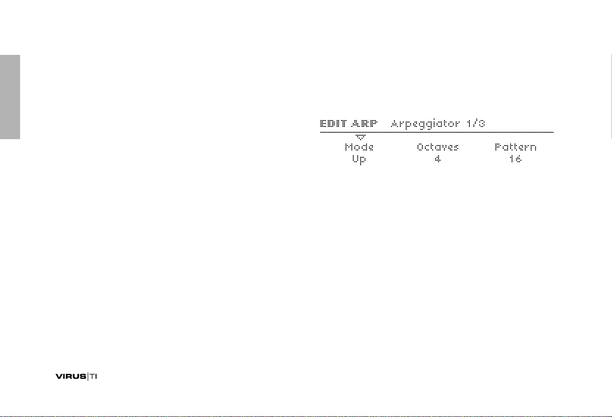
ARP
>EDIT MENU
ARP is short for Arpeggiator, a clocked processor that normally takes a chord and outputs individual notes, one after the
other. The Arpeggiator in your Virus also features repeated
chords, preset and custom rhythmic patterns, shuffle, infinite
hold etc.
>PANEL CONTROLS
EDIT
Opens the Arpeggiator menu (see opposite).
ARP ON
Toggles the arpeggiator on and off.
HOLD
Via SHIFT + ARP ON. Toggles the Hold function (see “Hold” on
page 78).
Arpeggiator
Mode
>Off: No arpeggiation. No other arpeggiator parameters will
be visible.
>Up: Ascending notes, starting with the lowest note
>Down: Descending notes, starting with the highest note
>Up+Down: Ascending then descending notes, starting with
the lowest note
> As Played: In the same order as received MIDI notes
>Random: Random note order, random octave (see Octaves
parameter below)
>Chord: Plays all entered notes at the same time.
76
Page 77

Octaves
Resolution
>1 to 4: Notes can be successively transposed up an octave at
the start of each new arpeggio cycle. The value here is equal
to the number of cycles before the arpeggio reverts to its
original pitch – so a value of 1 means no transposition.
Pattern
> User, 2 to 64: Selects the arpeggiator pattern. A “User” pat-
tern can be created for each program using the VirusControl
application (see “VirusControl” on page 145). As well as positions and lengths, most patterns contain extra velocity data
for added rhythmic effect. To apply velocity data, set the
Velocity parameters (see “Velocity Map” on page 132) or use
the modulation matrix (see “MATRIX” on page 79) with Velocity as the source. Modulation destination “Arp Pattern”.
> 1/128 to 1/2: The Arpeggiator’s rate expressed as a fraction
of a bar in 4/4 time. The minimum rate is therefore one complete arpeggio every 4/4 bar. The standard setting is 1/16 (i.e.
16 beats per bar), and normally does not need to be changed.
The actual rate is determined by the Tempo parameter – see
“Tempo” on page 129.
Note Length
> -64 to +63: Scales the lengths (hold time) of all notes. Nega-
tive values shorten the notes, positive values lengthen them.
The audible effect of this parameter is highly dependant upon
the envelope settings.
Modulation destination “Arp Note Length“.
Swing Factor
> Off, 50.2% to 75.0%: Affects the position (in time) of every
other 16th note. At 66% the rhythm is “full swing” i.e. triplets.
The values 16C, 16D, 16E and 16F are the same as those in
Apple Logic (a popular sequencer program). Note: Swing will
not affect the original “User” Pattern because this is made up
of steady 8th notes only. Modulation destination “Arp Swing“.
77 SOUND PARAMETERS REFERENCE
Page 78

Hold
Accessible from the panel via SHIFT + ARP ON.
>Off: The arpeggio stops as soon as all notes are released
>On: The arpeggio continues after notes are released. Playing
new notes after releasing all previous ones resets the arpeggio (i.e. the original notes disappear). Note that releasing a
Hold pedal will stop the arpeggio until new notes are played.
78
Page 79

MATRIX
>SELECT MENU
The modulation matrix is used for custom control routing. Six
sources can be routed to three destinations each. Available
sources include the internal envelopes and LFOs as well as
most MIDI controllers, channel pressure (aftertouch) etc.. The
list of destinations includes almost every Single Mode parameter in the Virus.
>PANEL CONTROLS
DESTINATION
This pair of buttons is used for up-and-down cursor control
within the menu (required because each page displays all three
destinations and amounts at once). Either of the DESTINATION
buttons will open the menu if it is not already open...
SELECT
Opens the modulation matrix menu. If pressed again, moves on
to the next slot (SHIFT + SELECT will move to the previous slot).
Alternative navigation: use the PARAMETERS buttons.
Slot
The information below applies to any slot in the matrix. Use the
DESTINATIONS buttons to move the cursor up and down.
Source
(VALUE 1 knob)
> Off, Pitch Bend ... Random: Specifies the modulation source
(envelopes, LFOs, MIDI controllers etc.). This source can be
simultaneously routed to a maximum of three destinations per
slot.
Amount
(VALUE 2 knob)
79 SOUND PARAMETERS REFERENCE
Page 80

> -64 to +63: Modulation amount for the specified destination.
The range is bipolar so that modulation can be inverted, and
amounts are internally doubled so that unipolar destinations
can be modulated over their entire range (i.e. 128 values).
The Amount itself can be controlled by another modulation
source – modulation destination is e.g. “Slot4 Amount2”.
Destination
(VALUE 3 knob)
> Off ... Wavetable 2 Index: Specifies a destination parame-
ter. Use the DESTINATION buttons to move the cursor up
and down.
80
Page 81

MODULATORS
Traditionally, LFOs (low frequency oscillators) are used for
cyclic modulation e.g. vibrato, tremolo etc.. Alternatively, two of
the three LFOs in the Virus can serve as simple envelopes (see
“Envelope Mode” on page 83), so the label “Modulators” seems
more appropriate than “LFOs” for this section.
Note that each LFO in the Virus has a different set of preset
destinations, and that LFO3 allows just one destination to be
selected.
>PANEL CONTROLS
EDIT
Opens the LFO menu corresponding to the selected LFO (see
SELECT below). Selecting a different LFO after opening this
menu will jump directly to the menu for the newly selected LFO.
ENV MODE
Toggles the Envelope Mode parameter on and off (see “Envelope Mode” on page 83).
SHAPE
Quick selection of Sine, Triangle, Sawtooth, Square or WAVE –
the waveform specified in the Edit menu (see “Shape” on
page 82).
RATE
Controls the speed of the currently selected LFO (see “Clock”
on page 82 and “Rate” on page 82).
LFO CONTOUR
Via SHIFT + RATE. Continuous control over LFO waveform (see
“Contour” on page 83).
81 SOUND PARAMETERS REFERENCE
Page 82

SELECT
These buttons are used to switch between the three LFOs –
the upper row of controls (ENV MODE, SHAPE and RATE) will
apply to the selected LFO only. Pressing an already active
SELECT button will jump into the LFO destinations menu, and
pressing it repeatedly will step through the pages.
>EDIT MENUS
> 1/64 ... 16/1: LFO1 rate is synchronized to the Clock,
expressed as a fraction of one bar in 4/4 time. See “Tempo”
on page 129.
Rate
Accessible from the panel via the RATE knob if “Clock” is set
to Off.
> 0 to 127: The speed of LFO1 when not synchronized (see
“Clock” above). Modulation destination “LFO1 Rate“.
LFO 1
Clock
Accessible from the panel via the RATE knob if a value is
defined here.
>Off: LFO1 is not synchronized.
Shape
> Sine, Triangle, Sawtooth, Square, S&H, S&G,
Waves 3 to 64: Specifies the LFO waveform. If S&H, S&G or
one of the additional waves is selected, this can be
accessed directly from the panel via the SHAPE button
(select “WAVE”). If Sine, Triangle, Sawtooth or square is
selected here, the status LEDs will move accordingly.
82
Page 83

Contour
Accessible from the panel via SHIFT + RATE.
Envelope Mode
Accessible from the panel via the ENV MODE button.
> -64 to +63: Continuous control over LFO waveform. Modula-
tion destination “LFO1 Contour“.
SHAPE NEGATIVE POSITIVE
Sine to Triangle to Square
Triangle to falling Saw to rising Saw
Saw concavity convexity
Square pulse width <50% pulse width >50%
S&H --- ---
S&G --- ---
3 to 64 zoom into wave ---
Mode
>Poly: Each voice has its own LFO, and these are slightly
detuned against each other.
>Mono: All voices share a common LFO. Only applies if the
parameters Envelope Mode and Trigger Phase (see below)
are both set to “Off”.
>Off: Standard (cyclic) LFO mode.
>On: The LFO effectively becomes an additional Envelope.
LFOs in Envelope Mode are unipolar (see glossary) and stop
after completing exactly one cycle. The start/finish point
within the wave can be specified via Trigger Phase...
Trigger Phase
> Off, 1 to 127: When set to Off, LFO1 runs freely i.e. its phase
is not reset by every note played (except in Envelope Mode).
All other values set the starting point within the wave.
83 SOUND PARAMETERS REFERENCE
Page 84

Key Follow
> Off, 1 to 127: How much LFO1 rate (see “Rate” on page 82)
is affected by MIDI note number. Note that Key Follow does
not apply when LFOs are in Envelope Mode (see “Envelope
Mode” on page 83) or are synchronized to the Clock (see
“Clock” on page 82).
LFO 2
All edit parameters for LFO2 are the same as those for LFO1 –
see “LFO 1” on page 82.
LFO 3
The edit parameters for LFO3 are the same as those for LFO1,
except that Contour, Envelope Mode and Trigger Phase are
not available in LFO3. See “LFO 1” on page 82.
>SELECT MENUS
LFO 1 Destinations
Osc1 Pitch
> -64 to +63: How much LFO1 modulates oscillator 1 pitch.
Modulation destination “LFO1>Osc1 Pitch“.
Osc1+2 Pitch
> -64 to +63: How much LFO1 modulates the pitch of all oscil-
lators, controlling the other two values in this page at the
same time.
Osc2 Pitch
> -64 to +63: How much LFO1 modulates oscillator 2 pitch.
Note that oscillator 3 automatically follows any pitch modulation applied to oscillator 2. Modulation destination
“LFO1>Osc2 Pitch“.
84
Page 85

Pulse Width
Assign Target
> -64 to +63: How much LFO1 modulates the pulse width of
both main oscillators. Modulation destination
“LFO1>Pulse Width”.
Resonance
> -64 to +63: How much LFO1 modulates the resonance of
both filters. Modulation destination “LFO1>Resonance“.
Filter Gain
> -64 to +63: How much LFO1 modulates the total level of all
signals before entering the filters. Modulation destination
“LFO1>Filter Gain“.
> Off, Amp Env Attack ... WaveTable 2 Index: Select from a
list of available destinations for LFO1.
Amount
> -64 to +63: How much LFO1 modulates the Target parame-
ter. Modulation destination “LFO1 Assign Amt“.
85 SOUND PARAMETERS REFERENCE
Page 86

LFO 2 Destinations
Cutoff 1
> -64 to +63: How much LFO2 modulates filter 1 cutoff fre-
quency. Like automating the CUTOFF knob when Cutoff
Link (see “Cutoff Link” on page 145) is switched off. Modulation destination “LFO2>Cutoff1“.
Cutoff 1+2
> -64 to +63: How much LFO2 modulates filter 1 and filter 2
cutoff frequencies simultaneously, controlling the other two
values in this page. Like automating the CUTOFF knob when
Cutoff Link (see “Cutoff Link” on page 145) is switched on
and CUTOFF 2 is set to 0.
Cutoff 2
> -64 to +63: How much LFO2 modulates filter 2 cutoff fre-
quency. Like automating the CUTOFF 2 knob. Modulation
destination “LFO2>Cutoff2“.
Shape 1+2
> -64 to +63: How much LFO2 modulates the shapes of oscil-
lators 1 and 2 simultaneously. Like automating the SHAPE
knob for both these oscillators at the same time. Modulation
destination “LFO2>Shape“.
FM Amount
> -64 to +63: How much LFO2 modulates the amount of fre-
quency modulation. Like automating the FM AMOUNT knob.
Modulation destination “LFO2>FM Amount“.
86
Page 87

Panorama
> -64 to +63: How much LFO2 modulates the position of the
signal across the stereo outputs. Like automating the PANORAMA knob (SHIFT + OSC BALANCE). Modulation destination “LFO2>Panorama“.
Assign Target
> Off, Amp Env Attack ... WaveTable 2 Index: Selects one of
the many possible destinations for LFO2.
Amount
> -64 to +63: How much LFO2 modulates the specified Assign
Target (see above). Modulation destination “LFO2 Assign
Amt“.
LFO 3 Destination
Fade In
> 0 to 127: The amount of LFO3 can be faded in after each note
is played: 0 = instantaneous, 127 = about 40 seconds. Particularly useful for delayed vibrato effects etc..
Assign Target
Unlike LFO1 and LFO2, LFO3 has only one modulation slot,
offering a choice of one of the following targets:
>Osc1 Pitch: Oscillator 1 pitch.
> Osc1+2 Pitch: The pitch of all oscillators.
>Osc2 Pitch: Oscillator 2 pitch. Note that oscillator 3 automat-
ically follows any pitch modulation applied to oscillator 2.
>Osc1 Pulse Width: The pulse width of oscillator 1.
87 SOUND PARAMETERS REFERENCE
Page 88

> Osc1+2 Pulse Width: The pulse width of both oscillators at
the same time.
>Osc2 Pulse Width: The pulse width of oscillator 2.
> Sync Phase: When Sync is switched on (see “SYNC” on
page 110), this defines the absolute phase of oscillator 2
each time it is reset by oscillator 1. Modulating Sync Phase
can cause effects similar to pulse width modulation, thus
giving the (typically rather cold) sync-sounds more warmth.
Amount
> 0 to 127: How much LFO3 modulates the selected target.
Note that, unlike the other LFOs, this is a unipolar parameter.
Modulation destination “LFO3 Assign Amt“.
88
Page 89

EFFECTS (upper row)
The upper half of the Effects section is responsible for delay,
reverb and 3-band equalisation, all of which can be applied
simultaneously.
>PANEL CONTROLS
SELECT
Determines whether the three knobs apply to DELAY, REVERB
or one of the EQ bands, and which menu will appear when the
EDIT button is pressed once.
EDIT
Opens the menu for DELAY, REVERB or one of the EQ bands,
depending upon which of these is currently selected.
SEND, EQ GAIN
If DELAY or REVERB is selected, this is an effect send control
(dry/wet mix). If one of the EQ bands is selected, this knob controls the Gain parameter.
TIME / COLOR, EQ FREQ
If DELAY or REVERB is selected, this is usually a Time control.
However, if one of the synchronized modes is selected (see
“Clock” parameters below), it controls the Coloration parameter
instead. If an EQ is selected, it controls the Frequency parameter.
FEEDBACK / DAMPING, EQ Q-FACTOR
If DELAY is selected, this is a feedback control. The same
applies for REVERB modes with feedback (see “Mode” on
page 92), otherwise it is a Damping control (see “Damping” on
page 93). If the MID EQ band is selected, it controls the MID EQ
Q-Factor (see “Q-Factor” on page 94). If LOW or HIGH EQ is
selected, this knob is inactive.
SHIFT+TIME/COLOR as well as SHIFT+FEEDBACK/DAMPING
will control the “other” parameter if both are available in the
selected effect.
89 SOUND PARAMETERS REFERENCE
Page 90

>EDIT MENUS
Delay
Send
Accessible from the panel via the SEND knob.
> Dry, 1 to 126, Wet: Effect send – actually a crossfade i.e. the
overall level remains fairly constant (the dry signal is faded
out at higher values). Modulation destination “Delay Send“.
Mode
>Off: No Delay effect.
> Simple Delay: Standard delay effect, the left and right chan-
nels have the same nominal delay times.
> Ping Pong 2:1 ... Ping Pong 8:7: The left and right channels
have different delay times, indicated by the ratio.
> Pattern 1+1 ... Pattern 5+5: The left and right channels can
have different delay times. Pattern modes are always synchronized to the Clock. The TIME / COLOR knob controls
the Coloration parameter (see “Coloration” on page 91).
Clock
> Off, 1/64 ... 3/4: Synchronized delay rate expressed as a 4/4
bar division. Although not labelled as such, this parameter
(or Delay Time – see below) is available from the panel via
the TIME / COLOR knob.
Delay Time
> 0.0 ms to 693.6 ms: Non-synchronized delay expressed in
milliseconds. This values is used if Clock (see above) is set
to Off. Available from the panel via the TIME / COLOR knob.
Modulation destination “Delay Time”.
90
Page 91

Feedback
Mod Rate
> 0 to 127: For repeated delays. Determines how much of the
output signal is fed back into delay input, affecting the
number of audible repeats. Modulation destination
“Delay Feedback“.
Coloration
> -64 to +63: Applies progressive filtering within the feedback
path (see “Feedback” above). Negative values make repeats
successively mellower, whereas positive values make them
brighter. Modulation destination “Delay Coloration”.
The Delay effect has its own dedicated LFO for modulating the
delay time. Note that this can cause interesting pitch modulation and stereo effects.
> 0 to 127: The speed of the delay LFO. Modulation destination
“Delay Mod Rate“.
Mod Depth
> 0 to 127: The amount of modulation applied to Delay Time by
the delay’s own LFO. Note that the left and right channels are
affected differently, so this parameter can be used to create
stereo effects.
Modulation destination “Delay Mod Depth”.
Mod Shape
> Sine, Triangle, Sawtooth, Square, S&H, S&G: The delay
LFO’s waveform. Use S&G for “tape echo” type effects.
Reverb
91 SOUND PARAMETERS REFERENCE
Page 92

In the signal path, delay and reverb are routed in series i.e. the
dry signal plus any delay is sent to the reverb input.
Mode
>Off: No effect. All other parameters will not be visible.
> Reverb: Standard reverb effect with predelay (see “Prede-
lay” parameter below).
> Feedback 1: Reverb effect with a feedback loop in the pre-
delay line, thus allowing multiple reverb tails.
> Feedback 2: The same as Feedback 1, except that the first
reverb tail appears immediately.
> Dry, 1 to 126, Wet: Effect send. Actually a cross-fade
between dry and wet – the overall level remains fairly constant. Modulation destination “Reverb Send”.
Clock
> Off, 1/64 ... 3/4: Used to synchronize Predelay to the Clock
(see “Predelay” below). Expressed as a 4/4 bar division.
Type
> Ambience, Small Room, Large Room, Hall: Different types
of room simulations, in order of size. This parameter affects
the so-called “early reflections”.
Send
Accessible from the panel via the SEND knob.
Time
Accessible from the panel via the TIME / COLOR knob
> 0 to 127: The length of the reverb tail. Modulation destina-
tion “Reverb Time”.
92
Page 93

Damping
> 0 to 127: For simulating different surface materials by pro-
gressively removing higher frequencies. Carpets and drapes
etc. tend to absorb a lot of high frequencies, while tiled floors
and walls do not. Modulation destination “Reverb Damping”.
Coloration
> -64 to +63: Post-EQ for the reverb signal. Negative values are
mellower, positive values are brighter. Modulation destination
“Reverb Coloration”.
Feedback
Only visible in Feedback 1 or Feedback 2 modes.
Accessible from the panel via the FEEDBACK knob.
> 0 to 127: How much of the reverb signal is fed back into it’s
own input. The repeat rate is determined by the Predelay
parameter (see “Predelay” above). Modulation destination
“Reverb Feedback”.
Low EQ
Predelay
Only visible if the Clock parameter is set to Off (see above).
> 0.0 ms to 300.4 ms: The time between the original signal and
the reverb signal, expressed in milliseconds. This can be fed
back for multiple reverb tails (see “Mode” on page 92). Modulation destination “Reverb Predelay“.
Frequency
> 32 to 458: Low shelf (1 pole) cutoff frequency in Hertz.
Gain
> -16 dB to +16 dB: Low shelf cut or boost.
93 SOUND PARAMETERS REFERENCE
Page 94

Mid EQ
Frequency
> 19 Hz to 24.0 kHz: Centre frequency of the MID EQ. Values
above 10,000 are given in kHz.
Modulation destination “EQ Mid Frequency”.
Q-Factor
> 0.28 to 15.4: Bandwidth around the centre frequency. Low
values are wider, high values are narrower. For wah-wah
effects, set very high Q-Factor and Gain values, then modulate “EQ Mid Frequency”.
Modulation destination “EQ Mid Q-Factor”.
Gain
> -16dB to +16dB: Mid frequency cut or boost, in decibels.
Modulation destination “EQ Mid Gain”.
High EQ
Frequency
> 1831 to 24.0: High shelf (1-pole) cutoff frequency in Hertz
(values above 10,000 are given in kHz).
Gain
> -16 dB to +16 dB: High shelf cut or boost.
94
Page 95

EFFECTS (lower row)
The lower half of the Effects section offers distortion, analog
boost, chorus and phasing effects, all of which can be applied
simultaneously. Effects which involve audio input (Vocoder,
Input Follower, Input Ring Modulator) are also available here
(see EDIT below).
>PANEL CONTROLS
SELECT
Determines which effect the knobs will control, and which menu
will appear when the EDIT button is pressed.
TYPE/MIX
If DISTORTION is selected, this controls the distortion Type (see
below). If ANALOG BOOST is selected, it controls the frequency
(see “Frequency” on page 97). If Chorus or Phaser is selected, it
controls the Mix parameter (see e.g. “Mix” on page 97).
INTENSITY
If DISTORTION or ANALOG BOOST is selected, this controls
the intensity parameter (see “Intensity” on page 97). If Chorus or
PHASER is selected, it controls the feedback parameter (see
“Feedback” on page 98 and “Feedback” on page 99).
>EDIT MENU
EDIT
Opens the menu for to the currently selected effect. Repeatedly
pressing EDIT toggles between the audio input effects pages
and the selected effect. See “Vocoder” on page 100, “Input Follower” on page 105 and “Input Ring Modulator” on page 106.
Distortion
The choice of “Distortion” effects in the lower EFFECTS section
are similar those available in the FILTERS menu (see “Saturation” on page 140), but here they treat the signal as a whole, i.e.
not each individual voice. The difference is particularly noticeable when playing chords.
95 SOUND PARAMETERS REFERENCE
Page 96

Type
Accessible from the panel via the TYPE/MIX knob
>Off: Distortion is disabled.
> Light, Soft, Medium, Hard: Four analog-style distortion
curves with differing characteristics.
> Rate Reducer: Variable reduction of sampling rate. For gen-
erating the aliasing effects typical of early samplers and digital synthesizers.
>Low Pass: Single pole low pass filter for variable reduction
of high frequencies. This effect is only included to ensure
compatibility with older programs (early Virus models did not
feature a dedicated EQ section).
> High Pass: Single pole high pass filter for variable reduction
of low frequencies. Also included for compatibility reasons.
Intensity
Accessible from the panel via the INTENSITY knob.
> Digital: Digital clipping. Can even turn a Saw wave into a
square wave.
> Wave Shaper: A sinusoidal waveshaper, the effect of which
is often similar to linear FM. Note that the results of the
Shaper are highly dependant upon the signal level (see
“OSC VOLUME” on page 137 and INTENSITY below).
>Rectifier: Full wave rectification with subsequent DC-com-
pensation. See glossary.
> Bit Reducer: Variable reduction of bit-depth. For generating
the digital quantization effects typical of early samplers and
digital synthesizers.
> 0 to 127: Generally determines the amount of effect. In the
two filter models (see “Low Pass” and “High Pass” above),
this is the cutoff frequency.
Modulation destination “Distortion Intensity“.
Analog Boost
Analog Boost can be used to emulate the frequency response
of various real analogue synthesizers. Note that boosting bass
frequencies will reduce the proportion of high frequencies in
the resulting signal.
96
Page 97

Intensity
Accessible from the panel via the INTENSITY knob.
> Off, 1 to 127: The degree of Analog Boost. Modulation desti-
nation “Analog Boost Int“.
Frequency
Accessible from the panel via the TYPE/MIX knob. Only visible if
Intensity is not set to Off.
> 0 to 127: The frequency where Analog Boost is applied. Very
high values will even boost mid-range frequencies.
the Chorus effect in your Virus is also capable of flanging,
ensemble, vibrato or resonator effects. Note that if the Mix
parameter is set to Off, the other parameters will not be visible
in the menu.
Mix
Accessible from the panel via the TYPE/MIX knob
> Off, 1 to 127: Cross-fade between the dry and wet signal. Set
this to 64 for maximum Chorus, or to 127 for a vibrato effects.
If set to Off, none of the other parameters in this menu will be
visible. Modulation destination “Chorus Mix“.
Delay
Chorus
Typically, Chorus is a thickening effect caused by modulating a
pair of very short delay lines via a dedicated LFO, then mixing
this with the original dry signal. In combination with Feedback,
> 0 to 127: The nominal delay time, modulated by a dedicated
LFO (see “Mod Rate” etc. below). Very high values result in a
short but noticable stereo delay effect. Modulation destination “Chorus Delay“.
97 SOUND PARAMETERS REFERENCE
Page 98

Feedback
Mod Shape
> -64 to +63: The amount of signal fed back into the Chorus
input. The Feedback parameter is bipolar because positive
and negative values have different tonal characteristics.
Modulation destination “Chorus Feedback“.
Mod Rate
> 0 to 127: Modulation rate – the speed of the dedicated LFO.
Modulation destination “Chorus Mod Rate”.
Mod Depth
> 0 to 127: How much the LFO modulates the Delay parame-
ter. Modulation destination “Chorus Mod Depth“.
> Sine, Triangle, Sawtooth, Square, S&H, S&G: Selects the
waveform used to modulate the Delay parameter.
Phaser
Typically, phasing is the classic “whoosh” effect originally
achieved by running two tape machines in parallel, then
slightly changing the speed of one of them. The Virus phaser
uses up to six “all-pass” filters to achieve a very similar effect.
In combination with Feedback, the Virus phaser is also capable of resonator, ensemble, vibrato and flanging effects. Note
that if the Mix parameter is set to Off, the other parameters will
not be visible in the menu.
Mix
Accessible from the panel via the TYPE/MIX knob.
98
Page 99

> Off, 1 to 127: Cross-fade between the dry and wet signal. Set
this to 64 for normal phasing (together with zero Feedback see below). Modulation destination “Phaser Mix“.
Frequency
> 0 to 127: The average frequency of resonant peaks (see
Spread below). Modulation destination “Phaser Frequency“.
Feedback
> -64 to +63: The amount of signal fed back into the Phaser
input, causing a resonance effect. The Feedback parameter is
bipolar because positive and negative values result in different tonal characteristics. Modulation destination
“Phaser Feedback“.
Mod Rate
> 0 to 127: Modulation rate – the speed of the Phaser’s dedi-
cated LFO (a triangle wave) used to modulate the Frequency
parameter (see above). Modulation destination
“Phaser Mod Rate“.
Mod Depth
> 0 to 127: How much the Frequency parameter (see above) is
modulated by the Phaser’s LFO. Modulation destination
“Phaser Mod Depth“.
Stages
>1 to 6: The number of all-pass filters used in the Phaser. This
value affects the complexity of the phased signal.
99 SOUND PARAMETERS REFERENCE
Page 100

Spread
> 0 to 127: How far apart the resonant peaks between multiple
stages are. Modulation destination “Phaser Spread“.
Vocoder
To enter these pages, press EDIT (lower EFFECTS section)
once or twice so that its LED flashes, then navigate using the
PARAMETERS buttons. Although available as “effect”, the
Virus Vocoder actually replaces the entire filter section i.e. Vocoder and normal filters cannot be used at the same time within
a single program.
The Virus vocoder has two banks of up to 32 bandpass filters:
One to analyse the frequency spectrum of a modulator audio
signal (see “Input Select” on page 134), and the other to process a carrier signal (usually the internal oscillators) accordingly. Please refer to the “Vocoder Table” on page 104.
As well as the functions of a few knobs in the filter section, two
of the parameters appearing in the first page of the vocoder
menu are sensitive to SELECT status in the Filters section: If
FILT1 is selected, carrier parameters will appear here. If FILT2
is selected, modulator parameters will appear.
Mode
Specifies the carrier signal...
>Off: The Vocoder is disabled, no other Vocoder parameters
will be visible.
> Oscillator: The carrier is the entire oscillator section, includ-
ing any noise.
>Osc Hold: Identical to “Osc” except that Hold mode (see
“Key Mode” on page 122) is activated for the vocoder.
>Noise: The carrier is the noise signal only. The rest of the
oscillator section is disabled, thus saving polyphony.
> In L, In L+R, In R: The carrier is one or both of the audio
inputs.
100
 Loading...