

Page 1

ENGLISH VERSION
Page 2

©1997-2002 Access Music GmbH, Germany.
This manual, as well as the software and hardware described in it, is furnished under licence
and may be used or copied only in accordance
with the terms of such licence. The content of
this manual is furnished for informational use
only, is subject to change without notice, and
should not be construed as a commitment by
Access Music GmbH. Access Music GmbH assumes no responsibility of liability of any errors
or inaccuracies that may appear in this book.
Except as permitted by such licence, no parts
of this publication may be reproduced, stored in
a retrieval system, or transmitted, in any form or
by any means, electronic, mechanical, recording, or otherwise, without the prior written permission of Access Music GmbH.
VIRUS is a trademark of Access Music GmbH.
All other trademarks contained herein are the
property of their respective owners. All features
and specifications subject to change without
notice.
Written by Christoph Kemper, Uwe G. Hönig,
Wiland Samolak and Marc Schlaile.
Translation by Thomas Green and Howard
Scarr.
http://www.access-music.de
info@access-music.de
Page 3

Page 4

4
CHAPTER 2
Content
Content
IMPORTANT SAFETY REMARKS .............................. 8
Master Clock And Midi-Clock................................ 50
The Effects Section............................................... 51
Audio Inputs .........................................................51
Audio Routing.......................................................53
Sound Categories .................................................53
Additional Functions .............................................54
PROLOGUE
INTRODUCTION
THE VIRUS ........................................................... 16
The Amplifier Envelope ........................................ 18
The First Filter...................................................... 20
Filter Modulation .................................................. 21
The Saturation Stage ........................................... 23
The Second Filter................................................. 23
Filter Routing ....................................................... 25
The First Oscillator ............................................... 27
The Second Oscillator .......................................... 28
The Mixer Section ................................................ 30
The LFOs ............................................................. 30
Soft Knob 1/2....................................................... 33
Volume and panorama ......................................... 33
Velocity................................................................ 34
Unison Mode........................................................ 34
The Effects........................................................... 35
The Arpeggiator ................................................... 37
SoundDiver Virus ................................................. 37
More to Come ...................................................... 38
CONCEPT AND OPERATION
Operating Modes ................................................. 40
OPERATION.......................................................... 43
All About The Memory.......................................... 46
Random Patch Generator ..................................... 47
Modmatrix And Soft Knobs................................... 49
THE PARAMETERS
OSC SECTION (ENCODER) .....................................58
Oscillator 1...........................................................58
Oscillator 2...........................................................58
Oscillator 3...........................................................59
Sub Oscillator.......................................................60
OSC SEKTION (MENU)...........................................61
Oscillator 1...........................................................61
Oscillator 2...........................................................61
Oscillator 3...........................................................63
Oscillators ............................................................64
Ringmodulator...................................................... 64
Noise.................................................................... 65
FILTER SECTION (ENCODER) .................................66
FILTER SECTION/MENU......................................... 67
Filter 1.................................................................. 67
Filter 2.................................................................. 68
Filters................................................................... 68
ENVELOPE SECTION (ENCODER) ...........................72
Filter Envelope...................................................... 72
Amplifier Envelope................................................ 72
LFO SECTION (ENCODER) .....................................74
LFO 1 ...................................................................74
LFO 2 ...................................................................75
LFO 3 ...................................................................75
LFO SECTION (MENU) ...........................................77
LFO 1 ...................................................................77
LFO 2 ...................................................................78
LFO 3 ...................................................................80
EFX SECTION (ENCODER)...................................... 82
Reverb ................................................................. 82
Delay.................................................................... 84
Chorus .................................................................85
Page 5

ACCESS VIRUS RACK XL OS5
5
Input .................................................................... 85
Analog Boost........................................................ 87
EFX SECTION/MENU............................................. 88
Delay/Reverb ....................................................... 88
Distortion ............................................................. 91
Phaser ................................................................. 92
Chorus................................................................. 93
Equalizer.............................................................. 94
Vocoder ............................................................... 94
EDIT SECTION/ENCODER...................................... 98
EDIT SECTION/MENU............................................ 99
Clock Tempo........................................................ 99
Common.............................................................. 99
Unison ............................................................... 102
Punch ................................................................ 103
Assign/Mod Matrix ............................................. 103
Velocity.............................................................. 106
ARPEGGIATOR&CTRL SECTION (ENCODER) ....... 108
ARPG&CTRL SECTION (MENU)............................ 110
Arpeggiator........................................................ 110
Categories ......................................................... 111
Second Output/Surround.................................... 111
THE MULTI MODE PARAMETERS
MULTIMODE PARAMETERS ................................ 114
The parameters of the Virus vocoder ..................131
Notes about the vocoder.....................................132
THE VIRUS AND SEQUENCERS
Parameter Control via MIDI .................................136
Organizational Information.................................. 136
Handling MIDI Parameter Control........................137
Notes on Adaptive Parameter Smoothing ............138
Problems Related to Parameter Control ..............139
Dump - The Sound in the Song........................... 140
TIPS, TRICKS& WORDS OF WISDOM
TIPS AND TRICKS ...............................................144
All abouts Inputs................................................. 145
About Effects......................................................145
Oscillators ..........................................................146
Filters................................................................. 147
Saturation for Added Grit and Dirt .......................147
LFOs .................................................................. 148
Volume Control...................................................150
Assign and the Soft Knobs..................................150
Arpeggiator ........................................................151
How to modulate the Vocoder parameters ..........151
MIDI ...................................................................152
The Operating System (OS)................................. 153
THE GLOBAL PARAMETERS
GLOBAL PARAMETERS/ SYSTEM SECTION ......... 120
Random Patch Generator ................................... 120
Input (Global) ..................................................... 120
MIDI................................................................... 122
System .............................................................. 125
THE VOCODER
Vocoder ............................................................. 130
APPENDIX
SYSTEM EXCLUSIVE DATA .................................158
System Exclusive Implementation....................... 158
Parameter Descriptions ......................................162
Multi Dump Table ...............................................174
Classes ..............................................................177
Mod Matrix Sources ..........................................179
Mod Matrix Destinations.....................................180
Soft Knob Destinations ......................................181
PDF VERSION - RESTRICTIONS APPLY
Page 6

6
CHAPTER 2
Content
MIDI Implementation Chart................................. 182
FCC Information (U.S.A)...................................... 184
FCC Information (CANADA) ................................. 184
Other Standards (Rest of World) ......................... 185
Declaration of Conformity................................... 186
Warranty............................................................ 187
Many thanks to .................................................. 187
INDEX
INDEX ................................................................ 190
Page 7

ACCESS VIRUS RACK XL OS5
7
PDF VERSION - RESTRICTIONS APPLY
Page 8

8
CHAPTER 3
Important Safety Remarks
PLEASE READ AND HEED THE FOLLOWING
SAFETY GUIDELINES!
A few fundamental rules on handling electrical
devices follow.
Please read all notes carefully before you power
the device up.
SET-UP
Operate and store the device in enclosed
rooms only.
Never expose the device to a damp environ-
ment.
Never operate or store the device in extreme-
ly dusty or dirty environments.
CONNECTIONS
Be sure to use exclusively the included mains
power supply adapter.
Plug the device only into mains sockets that
are properly grounded in compliance with statutory regulations.
Never modify the included power cord. If its
plug does not fit the sockets you have available,
take it to a qualified electrician.
Always pull the power plug out of the mains
socket when you won’t be using the device for
prolonged periods.
Never touch the mains plug with wet hands.
Always pull the actual plug, never the cord,
when you’re unplugging the device.
OPERATION
Don’t set beverages or any other receptacle
containing liquids on the device.
Assure that air can circulate freely on all sides
of the device, especially when you mount it to a
rack.
Don’t set the device in the immediate vicinity
of heat sources such as radiators.
Don’t expose the device to direct sunlight.
Don’t expose the device to strong vibrations
and mechanical shocks.
Make sure the device is placed on a solid
base. Set it on a stable tabletop or mount it to a
rack.
Make sure that no foreign objects fall into or
somehow end up inside the device’s housing.
In the event that this should occur, switch the
device off and pull the power plug. Then get in
touch with an authorized dealer.
Page 9

ACCESS VIRUS RACK XL OS5
9
Used on its own and in conjunction with
amps, loudspeakers or headphones, this device
is able to generate levels that can lead to irreversible hearing damage. For this reason, always operate it at a reasonable volume level.
MEMORY BATTERY CHANGE
The Virus stores its sound programs in a battery-buffered RAM. This battery (general type
designation: CR2032) should be replaced every
three to four years. The housing has to be
opened to change the battery, so take the device to a qualified service technician. Do your
part in protecting our environment and take it to
a shop that disposes of batteries properly.
Before you have the battery changed, save the
entire memory content of the RAM by loading it
to a sequencer via "Total Dump". Be advised
that RAM content is lost when the battery is
swapped. [“Midi Dump TX” on page 122]
CARE
Do not open the device, it is not equipped
with any user-serviceable parts. Repair and
maintenance may only be carried out by qualified specialists.
FITNESS FOR PURPOSE
This device is designed exclusively to generate
low-frequency audio signals for sound engineering-related purposes.
Any other use is not permitted and automatically invalidates the warranty extended by Access
Music Electronics GmbH.
Use only a dry, soft cloth or brush to clean the
device.
Do not use alcohol, solvents or similar chemi-
cals. These can damage the surface of the
housing.
PDF VERSION - RESTRICTIONS APPLY
Page 10

10
CHAPTER 3
Page 11

Prologue
Page 12

12
CHAPTER 4
Prologue
Dear Virus Owner,
Congratulations on your choice, the new Virus.
You have purchased a cutting-edge synthesizer
that comes fully loaded with several revolutionary features. Here are just a few of the highlights:
The Virus delivers the sound characteristics and
tone of traditional analog synthesizers - for instance the Prophet 5 or Memorymoog to name
just two popular examples of the species - in a
previously unparalleled level of quality and handling ease. We’re not kidding, the Virus actual
delivers the authentic response of an analog
synth via a digital signal processor, although the
sound shaping and voicing options out-perform
those of it historical predecessors by a considerable margin.
The Virus comes with 1024 slots for storing
SINGLE sounds. These are organized in four
banks. The first two banks (A and B) are located
in the RAM, so you can overwrite them with
new sounds. The other two banks are ”hardwired”, i.e. they’re programmed into the FLASH
ROM.
The Virus rack XL offers a maximum of 32 voices. In Multi Mode, these are allocated dynamically to 16 simultaneously available sounds.
You have up to three audio oscillators plus one
suboscillator, a noise generator, a ring modulator, two Multi Mode filters, two envelopes, a
stereo VCA, three LFOs and a saturation stage
(SATURATOR) for cascade filtering, tube and
distortion effects.
The Virus offers a veritable number of effects.
Yo u have a powerful Chorus/Flanger section at
your disposal, as well as the Analog Boost - a
controllable bass emphasis, with each effect
available separately for every sound. Furthermore there is a 6-stage Phaser, and a patch
Distortion. You also get a global reverb/delay
unit that lets you create high-quality reverb effects and rhythmic delay taps. Delay time can
be synced up to MIDI clock.
With the benefit of two external audio inputs,
the Virus may also serve as an FX device and
signal processor that you can use creatively to
come up with all kinds of effects. External signals can be processed with filter, gate and lo-fi
effects, routed to the Virus effects section and
serve as a modulation source for frequency and
ring modulation.
Beyond that, you can use internal or external
signals as sources for the Virus’ on-board vocoder serve. The vocoder works with up to 32 filter bands and offers diverse manipulation and
modulation options.
You'll find parallel external audio inputs on the
front and back panel. You can determine the input sensitivity via a gain selector switch. You're
also free to activate a special Phono EQ that
enables you to connect a record player via a
suitable cord.
The up to three main oscillators produce 66
waveshapes, three of which are dynamically
mixable so that spectral effects are possible
within the confines of a single oscillator. In conventional synthesizers, this type of effect requires several oscillators. Synchronization,
frequency modulation and ring modulation between the audio oscillators delivers additional
complex spectral effects that you can use for all
kinds of sound shaping purposes.
The filters can be switched in series or in parallel within the voices via several options. When
you switch the filters in series, the saturation
stage is embedded between the filters. Consequently, an overdriven filter resonance can be
re-filtered within the same voice! A maximum of
six filter poles (36 dB slope!) enables radical
tonal manipulations.
Page 13

ACCESS VIRUS RACK XL OS5
13
The LFOs feature 6 continuous variable waveshapes each, including a triangle with variable
symmetry and infinitely variable aperiodic oscillations for random variation of the controlled
parameters. The LFOs are capable of polyphonic as well as monophonic oscillation. In
other words, if several voices are active, the
LFOs can run independently or in sync. A
number of keyboard trigger options enable you
start LFO waveshapes with variable phase
lengths at the beginning of a note and/or to cycle once only, like an envelope.
Next to the numerous ”hard-wired” or fixed
modulation configurations, you can assign six
modulation sources to up to nine different modulation destinations via the Modulation Matrix.
For your modulation sources, you have LFOs,
velocity, the pitch bender, aftertouch, the modulation wheel, numerous MIDI controllers and
other sources to chose from. For your modulation destinations, you can select any sound parameter of the Virus that is conducive to being
remote controlled.
Up to 16 arpeggiators are available in MULTI
mode. These give you countless options for
creating arpeggios, which can also be synced
up to MIDI clock.
Sounds and effects are patched out via four audio outputs which of course can also be used to
route two stereo signals out.
The Virus rack XL comes with a powerful software editor for PC and Macintosh. It lets you
edit and manage sounds on a large-scale user
interface. You can access every sound parameter of the Virus rack XL directly via mouse click.
When you edit a parameter, the Virus will render
the changes immediately in real time. Accordingly, every parameter change that you make
using the encoder knobs (those knobs without
left and right control range limits) on the Virus
rack XL appears immediately on the screen. Incidentally, this editor is based on Emagic's popular SoundDiver.
In all modesty, we are especially proud of a feature we developed called Adaptive Parameter
Smoothing. For the first time in the history of
synthesizers equipped with memories, you can
manipulate a knob or control feature without an
audible step or increment. In other words, the
sound does not change abruptly but SEAMLESSLY. No more zipper noises! The Virus responds just as smoothly as analog synthesizers
did prior to the introduction of digital sound
storage.
And users of contemporary software sequencers will appreciate the fact that the Virus sends
all sound shaping commands immediately in
the form of MIDI Controller or Poly Pressure data (and of course accepts all of the corresponding Controller and SysEx messages). This
feature lets you dynamically control the Virus
and all its functions via computer.
Although far from complete, the features listed
above give you some indication that you now
own an exceptionally versatile, high-quality musical instrument that will give you plenty of joy
for years to come. We certainly hope you can
fully exploit the enormous potential of this fine
instrument.
Have fun and enjoy!
Your Virus Development Team
PDF VERSION - RESTRICTIONS APPLY
Page 14

14
CHAPTER 4
Prologue
Page 15

Introduction
Page 16

16
CHAPTER 5
Introduction
The Virus
This section provides deliberate, step-by-step
guidelines on operating and handling the Virus
for those of you who are new to the world of
synthesizers and MIDI. The following covers basics such as how to connect the Virus to an AC
power supply, your MIDI system and your audio
system. Then we will guide you through a series
of experiments designed to demonstrate the
different functional groups, their control features and the tasks they execute.
After you have finished reading this section, you
will be able to handle virtually all of the sound
generating and sound shaping functions of the
Virus. All of these are described in context.
Even the majority of less significant functions,
accessible via menus, are discussed here. You
will find a detailed, comprehensive description
of all functions of your new synthesizer in the
section following this introduction.
Please keep in mind that within confines of this
introduction, we are unable to impart all of the
knowledge and skills in acoustics, sound synthesis and MIDI control you might desire or
need to acquire. If you are keen to learn more
about these subjects, you should consider becoming a regular reader of one or several of the
leading trade publications in your country. Your
local musical instruments dealer or more experienced musicians will be able to recommend
the best magazines to you. And of course there
is a wide range of books available on these
subjects.
If you decide to read this section, we recommend you read it in its entirety from the start rather than begin with a subsection that is of
particular interest to you. A fitting metaphor for
the basics discussed in this section might be a
house where each bit of information in a sub-
section is a brick that builds on a preceding
brick and interlocks with those next to it. You
want your knowledge base to be a sound structure so you won’t run into problems when you
find one of the “bricks” is missing.
CABLE CONNECTIONS
Before you connect the Virus to an AC outlet
and the rest of your equipment, ensure that all
of the devices are switched OFF. If your Virus
does not have a build-in keyboard, then connect the MIDI OUT of the desired MIDI send device (keyboard, computer, hardware sequencer,
etc.) with the MIDI IN of the Virus.
Connect the audio outputs of the Virus with the
signal inputs of your audio system. In order to
receive a signal, as a minimum you must connect the output OUT 1 R/MONO. However, we
recommend you also connect the output OUT 1
L so you are able to enjoy the stereo sounds of
the Virus.
Once you have established the desired cable
connections, make sure the main volume controls of all the connected devices are dialed to
the lowest possible setting. Switch the devices
on in the following sequence: the MIDI send device (computer, master keyboard, etc.) first,
then the sound generators (Virus and the other
signal sources), followed by the mixing console
and finally the amplifier.
POWER UP THE VIRUS RACK XL
Power up the Virus rack XL by pressing the
POWER button. To shut the device down, press
and hold this button for approx. two seconds.
Now while you are sending notes on MIDI
Channel 1 of the Virus, turn the master volumes
of the connected devices up in the same order
Page 17

that you switched the devices on. Be sure to
keep on eye on the signal level indicators of
your mixing console.
LISTENING TO THE FACTORY SOUNDS
The program memory of the Virus was loaded
with sound programs (SINGLE PROGRAMs)
and sound combinations (MULTI PROGRAMs)
before it left the factory. To hear the SINGLE
PROGRAMs (and gain an initial impression of
the possibilities your new instrument has to offer in terms of sounds), first make sure your
MIDI source is sending on MIDI Channel 1.
Press the SINGLE button. A number, a letter,
number and name appear in the display. These
indicate the the MIDI Channel, the current Program Bank (A to H) as well as the number and
name of the current sound program.
Now if you play notes you should be able to
hear this sound and a quarter note (the round
dot at the end of the note staff is solid black)
should appear in the display every time you
press a key and release a key. If you do not hear
a sound but you see a half note (blank note
head) check to see if you are sending on the
wrong MIDI Channel.
Press the VALUE button to call up the 128 single programs of Bank A in sequence. (The VALUE encoder is inactive in this operating mode.)
In order to hear the sound programs in banks B
to H, simply use the PARAMETER/BANK buttons to step from one program bank to another.
You’ll find that some sound programs are labeled with the abbreviations ”INP” or ”VOC”.
These use the external audio input as a signal
source for the filter section (INP) or vocoder
(VOC). This means that you won’t hear anything
until you route an audio signal into the external
audio inputs.
ACCESS VIRUS RACK XL OS5
LISTENING TO THE MULTI PROGRAMS
The Virus not only has the capability of playing
SINGLE PROGAMs, but also combinations
consisting of more than one sound simultaneously (MIDI Multi Mode). To call up the MULTI
PROGRAMs, press the MULTI button and select these combination programs via the VALUE
button. The Virus features “only” 128 MULTI
PROGRAMs, so you don’t have to switch back
and forth between banks they way you just did
while activating single programs.
The majority of available MULTI PROGRAMs
contain sound combinations that are controlled
via a single MIDI channel. In these MULTI PROGRAMs, the sounds involved are allocated
side-by-side (split) or on top of one another
(layered) on the keyboard. In other MULTI PROGRAMs, the sounds are divided up over several
MIDI channels to make it easier to work with a
sequencer. If you activate a MULTI PROGRAM
and hear a single sound only, then you can control this MULTI PROGRAM via several channels.
17
PDF VERSION - RESTRICTIONS APPLY
Page 18

18
CHAPTER 5
Introduction
SOUND CATEGORIES
To help you find the type of SINGLE sound you
are looking for more quickly, the Virus operating
system lets you define so-called „categories“
and save this information together with each of
your SINGLE sounds.
Each SINGLE sound can „belong“ to two categories at the same time. Of course the categories of all the presets in Banks C to H are fixed,
but for sounds in the RAM Banks (A and B) they
can be defined and saved together with the
program.
To search for sounds in a specific category (in
SINGLE or MULTI-SINGLE mode):
Press and hold the SINGLE button. This causes
the currently selected category to appear in the
display, and it can be changed by stepping up
or down with the Parameter buttons. Having
found the category you want, do not release the
SINGLE button and scroll through the sounds
using the Value buttons. Release the SINGLE
button when you have found what you are looking for. SINGLE sounds which do not belong
to the currently selected category are simply
skipped over.
should end abruptly. This sound is not designed
to be especially pleasant; it is intended to be as
neutral as possible to give you a basis from
which you can begin creating or shaping your
own sound.
THE AMPLIFIER ENVELOPE
Long-term exposure to this sound will definitely
grate on your nerves, so let’s get started with
changing it into a signal you might enjoy hearing, beginning with the volume characteristics.
Locate the two vertically arrayed buttons next
to the seven LEDs. Use these UP and DOWN
buttons to select from among the seven parameter groups and/or sections. The appropriate
LED lights up to indicate that the given section
has been selected. Select the ENV section. The
labels on the five encoder knobs for this section
read ATTACK, DECAY, SUSTAIN, SUS TIME and
RELEASE.
YOUR FIRST SOUND PROGRAM
If you have never created or changed a sound
on a synthesizer, we now have the pleasure of
introducing you to this fascinating process.
Press the button
program “A127 - START -” by using the
buttons. Press any key on the connected keyboard. You should hear a sound that, for lack of
better description, is a bit harsh or biting, but
above all completely static. It should start immediately after you press a key and sustain indefinitely for as long as you hold the key down.
As soon as you release the key, the sound
SINGLE
and select the single
VALUE
These controls will help you to dial in volume
characteristics called an amplifier envelope and
put an end to the nerve-racking drone that may
remind you of one of those cheesy organs that
you hear in ‘60s B-movie sound tracks.
The section labeled ENV addresses the envelope. On a synthesizer, an envelope is used to
modulate sound over time. The Virus has two
envelopes, one for volume (AMP ENV) and one
for the filters (FILT ENV), which we will learn more about later. The five encoder knobs serve to
shape either the amplifier envelope or the filter
envelope. Make sure that you can see AMP
ENV in the display, and not FILT ENV. If this is
not the case, use the PARAMETER buttons to
set the section to the amplifier envelope.
Page 19

ACCESS VIRUS RACK XL OS5
The Amplifier Envelope
Whenever the SUSTAIN level is set to maximum, the volume cannot drop during the DECAY phase; in other words, in this situation the
DECAY encoder is ineffective.
The individual functions of a synthesizer are
designed to interact; many functions are dependent on other functions. In a number of cases this means that some functions are
subordinate to others, i.e. the effectiveness of a
control feature is altered, modified or even negated completely by other related functions.
19
Rotate the ATTACK encoder while you repeatedly engage a key to hear the note. The further
you turn the encoder up, the longer it takes for
the sound to achieve maximum volume after
the start of the note. So you can say ATTACK
controls the initial volume swell of the sound.
Take a look at the display of the Virus to gain an
impression of the difference between these two
values. It shows two numeric values when you
dial a encoder: at the left you can see the value
stored in the sound program and at the right,
the numeric equivalent to the value determined
by the current position of the encoder.
Now fiddle with the DECAY encoder while you
repeatedly press a key to activate a note. Hold
the key down for good while. You will notice
that the volume, once it reaches maximum level
at the end of the ATTACK phase, drops until it
reaches a minimum level. The DECAY encoder
determines the speed, or in synthesizer jargon,
the rate at which the volume decreases.
However, the DECAY level does not always
drop to the minimum level; you can determine a
random value between the maximum and minimum levels at which the volume remains constant. This level in turn is controlled via the
SUSTAIN encoder.
The final encoder, RELEASE, determines the
speed or rate at which the volume decreases
when you release the key: At low values the
sound ends relatively abruptly, at high values,
the sound fades out more gradually and softly.
The length of the RELEASE phase also depends on which level the amplifier curve is at
when you release the key: The lower the level,
the shorter the RELEASE phase. If you dialed in
a brief DECAY or SUSTAIN-TIME phase and it
ended while you held the key down then of
course there will not be an audible RELEASE
phase.
The next phase of the amplifier envelope is determined by the SUSTAIN-TIME encoder: If the
encoder is set to the center position, then the
SUSTAIN level remains constant through to the
end of the note.
If you turn it counter-clockwise to the left, then
the level drops off at an increasing rate towards
the minimum level much in the manner you just
experienced with the DECAY encoder; If you
turn the encoder clockwise to the right, the level
rises at an increasing rate to maximum and
remains there until you release the key.
T he amplifier envelope can be described as a
variable curve which, depending on the type
and duration of attack, hold and release data,
PDF VERSION - RESTRICTIONS APPLY
Page 20

20
CHAPTER 5
Introduction
automatically influences an imaginary volume
encoder (turns it up or down). At the beginning
of the note, ATTACK controls the rise or rate of
increase to the maximum level. Once the maximum level is achieved, DECAY determines the
fall or rate of decrease to the SUSTAIN value,
which is infinitely variable between the minimum and maximum levels. The amplifier envelope may remain at this value until the end of
the note, fall towards the minimum level as determined by the variable TIME value, or even rise again towards the maximum level. After the
end of the note, RELEASE controls the fall or
Now we will take a look at a component of a
synthesizer that is generally regarded as the
most important functional unit as it enables drastic sound shaping measures: the filter - or in
the case of the Virus, the two filters.
But first we will concentrate on just one of the
two filters.
rate of decrease to the minimum level. Consequently, the control encoders labeled ATTACK,
DECAY, TIME and RELEASE control a speed or
rate, where as SUSTAIN actually controls a level.
THE FIRST FILTER
most pronounced, adjust the amplifier envelope
so that the Virus generates a constant level while you hold a key down).
This is how a low pass filter works: it suppresses, or in technical jargon, attenuates the higher
frequencies in a signal and allows the lower frequencies through. Think of the CUTOFF encoder as a bouncer and the Virus as your pub. You
can tell it which frequencies to let in and which
frequencies to keep out. The frequencies above
the so-called cutoff or filter frequency are suppressed, those below it remain unaffected.
Use the UP or DOWN buttons to activate the filter section FILT. The second encoder knob in
this row is labeled CUTOFF (not to be confused
with CUTOFF 2!). Rotate the encoder to the left
and right and note how the sound becomes
muddier and clearer in response to the direction
in which you turn the encoder. (To ensure this
effect and the following aural experiments are
Now we'll look at a parameter that is not assigned a dedicated knob of its own, but can be
dialed up in the display. This type of parameter
may be selected via the PARAMETER buttons
and then adjusted with the VALUE knob or the
VALUE buttons.
Select the FILTER 1 Mode parameter via the
PARAMETER buttons. To do this, make sure
that the display is still in the filter section FILT.
This parameter enables you to select a filter
operating mode from the four available options:
- LOWPASS
discussed.
the low pass filter we have just
Page 21

ACCESS VIRUS RACK XL OS5
Filter Modulation
21
- HIGHPASS
in the opposite manner of the low pass filter:
It suppresses the lower frequencies in a signal and lets the higher frequencies pass.
- BANDPASS
presses both ends of the tonal spectrum and
allows only a narrowly defined bandwidth of
the original sound to pass.
- BANDSTOP
filter or notch filter which works in the opposite manner of the bandpass filter. It allows all
of the frequencies of a signal except for a narrow frequency band around the cutoff to
pass. The term “notch” is fairly descriptive;
you might say this filter chops a notch out of
the sound spectrum.
01111111111111111112
the high pass filter which works
the band pass filter which sup-
The band stop filter, band reject
1 FILTER1
Mode Lowpass≤
61111111111111111154
Now activate the different operating modes and
rotate the CUTOFF encoder to get a feel for the
way each filtering option works.
Along with the CUTOFF encoder, the RESONANCE encoder is the most important control
feature of a filter. The filter resonance increases
the volume of the frequencies located near the
cutoff frequencies and suppresses the more remote frequencies. This sound shaping feature
has a striking effect - especially when used in
conjunction with the low pass filter: it produces
a nasal or honking type of tone which increases
as you turn the resonance up. Experiment by
varying the RESONANCE setting in the different
operating modes in conjunction with different
CUTOFF settings. You will find the effect that
the RESONANCE encoder achieves is markedly
different for the band stop filter in comparison
to the effect it has on the other filter types: as
the resonance increases, the bandwidth of the
notch decreases; in other words more frequencies on both sides of the filter frequency are allowed to pass.
FILTER MODULATION
Of course we don’t want to require you to execute every sound modification manually by
twiddling encoders. All kinds of sound modifications in the Virus can be executed automatically much in the way of your previous
experiments with the volume controls: The amplifier envelope can be described as a variable
curve which, depending on the type and duration of attack, hold and release data, automatically influences (turns it up or down) an
imaginary volume pot.
Similar procedures are applicable to the filter
frequencies. The FILTERS section features its
own envelope, the structure of which is identical to the amplifier envelope.
Like the aforementioned amplifier envelope, the
filter envelope is located in the ENV section. In
that section use the PARAMETER buttons to
select FILT ENV.
Much like the amplifier envelope, the filter envelope automatically “rotates” the CUTOFF encoder. However there is one significant
difference between the two envelopes. With the
amplifier envelope, you are always dealing with
an initial volume level of 0 because of course
you want absolute silence prior to the beginning
of a note. After the RELEASE phase, it is again
highly desirable that your box is silent. With the
filter envelope, the situation is somewhat different: It always starts at the CUTOFF value that
PDF VERSION - RESTRICTIONS APPLY
Page 22

22
CHAPTER 5
Introduction
you determined manually. And it is definitely
not always desirable that the filter frequency is
brought to the maximum level.
Consequently, you need a tool that limits the effective range of the filter. This is why we
equipped the Virus with a control labeled ENV
AMOUNT (short for Envelope Amount). This encoder is positoned in the Filter section. When
the encoder is turned counter-clockwise to the
far left, the filter has no effect on the cutoff frequency; the further you turn the encoder to the
right, the greater the effect the filter envelope
has on the filter frequency. The maximum level
of the envelope may lie outside the audible
range when the filter has already been partially
opened via the CUTOFF encoder or was manipulated via other control options. In extreme cases where the filter is already completely open,
the filter frequency cannot be increased regardless of how high you set the ENV AMOUNT.
Go ahead and spend some experimenting with
different ENV AMOUNT, CUTOFF and RESONANCE settings for the diverse filter operating
modes. Also try varying the settings for the amplifier envelope. You will find that with just these
few parameters you are able to come up with a
vast amount of sound settings. If you are
among the many musicians who are associative
listeners, you might say many of the settings
produce sounds reminiscent of stringed-instruments; some sound picked, plucked or
snapped, others sound bowed.
For your next experiment set the amplifier envelope so that you hear a constant level when you
press and hold a note. Now deactivate the filter
envelope by setting the ENV AMOUNT to 0. Set
Filter-1Filter-1 to low pass mode and decrease
the filter frequency until you just barely hear a
muddy signal when you play notes in the midrange.
Now play a few higher and lower notes. You will
find that the lower notes have a greater overtone content, whereas the higher notes sound
muddier and their volume decreases until the
notes are completely inaudible. You might already suspect what this is all about: As the
notes are transposed ever lower, more portions
of the signal fall below the cutoff frequency,
whereas with the notes that are transposed ever higher, more portions of the signal rise above
the cutoff frequency and subsequently are suppressed until the root note and the last audible
portion of the signal is silenced.
To avoid this effect - or if desirable, to amplify it
- you have the option of influencing the cutoff
frequency via the pitch of the note, i.e. the note
number. The degree of influence is determined
by the KEY FOLLOW parameter. You'll find this
parameter in the filter section using the PARAMETER buttons just like you did in FILTER 1
mode earlier on.
Please note that KEY FOLLOW is a so-called
bipolar parameter: Its control range is not limited to the positive end of the spectrum (0 to a
maximum of 127). Bipolar controls effect negative values as well, in this case from the negative maximum of -64 through 0 an on to the
positive maximum of +63. Consequently, if this
value is set to the center position (0) the pitch of
the notes corresponding to the keys on your
keyboard has no effect on the cutoff frequency.
If on the other hand you turn the KEY FOLLOW
parameter clockwise towards the positive control range, you will find that the filter opens up
increasingly as the pitch increases with higher
notes. At lower notes, the filter closes down
again. If you turn the encoder counter-clockwise towards the negative control range, the
KEY FOLLOW effect is reversed. With the Virus,
you will encounter this feature - intensity control
via a bipolar parameter - again in conjunction
with other modulation sources and targets.
Page 23

ACCESS VIRUS RACK XL OS5
The Saturation Stage
23
Now experiment as much as you like with different KEY FOLLOW settings and tune the settings via the CUTOFF encoder. And remember
to bring all of the other parameters you have
encountered thus far into play.
THE SATURATION STAGE
In the signal chain of the Virus, Filter-1 is followed by a saturation stage. It enables you to
add overtones to the filtered signal via distortion. Locate the parameter SATURATION in the
FILTERS section.
01111111111111111112
1 SATURATION
Curve Off≤
61111111111111111154
The display will read ”SATURATION CURVE
OFF”, which means exactly what it says. With
the VALUE buttons or the VALUE encoder, you
can now select from a number of saturation/distortion curves.
At this point we would like to mention the OSC
VOL parameter, which is next to the SATURATION parameter. The portion of the control
range from the far left to the center position (0)
determines the volume of the filter section’s input signal. The portion of the control range located to the right of the center position does
not achieve any increase in volume; it simply
intensifies the degree of saturation or distortion.
This effect is only achieved when you have activated a saturation curve.
Feel free to experiment with the diverse satura-
tion curves and be sure to vary the OSC VOL
settings. Note how the different CUTOFF and
RESONANCE settings influence the saturation
curve.
THE SECOND FILTER
You probably noticed that by a adding a bit of
saturation to the signal you can come up with a
pretty heavy, aggressive sound - especially with
a low filter frequency level and high resonance.
Yo u’re probably thinking these types of sounds
could do with some more filtering. We had the
same idea, which is one of the reasons why we
equipped the Virus with another filter per voice.
The technical design of this second filter is
identical to the first, so we won’t discuss it in
as much detail as we did the first filter. However, there are few differences in how you handle
the second filter:
A Only two parameters of the Virus are allocated exclusively to Filter-2: CUTOFF 2 and FILT 2
MODE.
A The RESONANCE, ENV AMOUNT and KEY
FOLLOW parameters can be allocated to either
of the two filters or both simultaneously. Use
the FILTER SELECT menu in the FILTERS section to select the desired operating mode. For
instance, if you choose FILT2, then the values
you set with RESONANCE, ENV AMOUNT and
KEY FOLLOW apply exclusively to Filter-2. The
corresponding parameters of Filter 1 remain unaffected. On the other hand, if you choose
FILT1+2, the values that you dial in apply by the
same measure to Filters 1 and 2.
PDF VERSION - RESTRICTIONS APPLY
Page 24

24 CHAPTER 5
Introduction
In the sound program we are using for our experiments, both filters are selected, so that all
adjustments to the given parameters affect
both filters. However, you have yet to actually
hear the effect of Filter-2 on the signal because
it is mixed out of the audible signal path of the
Virus.
Before we get started with our next experiment,
deactivate SATURATION, set the ENV AMOUNT
of the filter envelope to zero and set CUTOFF 2
to the center position so that Filter-2 always has
the same cutoff frequency as Filter-1 (we’ll explain CUTOFF 2 a bit later). Set CUTOFF to a
medium or middle value and turn the RESONANCE encoder counter-clockwise to the far
left to achieve a relatively muddy sound.
Now locate the FILTER BALANCE parameter in
the FILT menu and rotate it from the left to the
right. You will note the sound becomes muddier
as you turn the encoder towards the center position and that the sound is somewhat brighter
at the far right of the control range then at the
far left.
The reason for this effect is that when you turn
the FILTER BALANCE to the far left, only Filter1 is audible. When you rotate the parameter to
the right, Filter-2 is blended in so that it follows
Filter-1 in the signal chain. When you turn the
FILTER BALANCE clockwise, Filter-1 is blended
out of the signal chain until at the far right position only Filter-2 is active and audible.
Each filter in the Virus normally features 2 poles.
However in the FILTER ROUTING operating
mode SER 6, Filter-1 operates with 4 poles, so
the signal patched through Filter-1 (FILTER
BALANCE to the far left) is trimmed more drastically than when it is routed through Filter-2
(FILTER BALANCE to the far right). When you
set the FILTER BALANCE to the center position
(12 o’clock) - as we mentioned before - the two
filters are routed in series, which means they respond as if they were a single filter with 6 poles
and consequently a great deal of slope. This is
why the input signal is trimmed substantially
when you set the parameter to this position.
Experiment with the diverse FILTER BALANCE
values to get a feel for the different degrees of
slope. Rotate the CUTOFF encoder or activate
the filter envelope (for both filters!) to hear the
filters in action.
The CUTOFF 2 parameter is a special feature: It
controls the cutoff frequency of the second filter, but is subordinate to the CUTOFF encoder
located above it. In other words, at the center
position (12 o’clock) the manually selected frequency of Filter-2 is identical to that of Filter-1.
When you rotate the encoder to the left the cutoff frequency level of Filter-2 is increased relatively to Filter-1, when you turn to encoder to
the right the cutoff frequency level is decreased
relatively. Now when you adjust the CUTOFF,
you adjust the cutoff frequency of both filters by
the same measure! This feature lets you determine a difference in values in the filter frequencies (called an offset) via the CUTOFF2 encoder
which remains constant whenever you adjust
the CUTOFF encoder.
Yet another experiment in which you can come
up with new filtering characteristics that are
typical of the Virus:
Set FILTER BALANCE to the center position
(12 o’clock) and CUTOFF 2 to the maximum
level. The FILTER ROUTING operating mode
must remain SER 6. Set CUTOFF and RESONANCE to a middle value and select a clearly
audible SATURATION curve.
Now you can filter this complex signal produced by a combination of the saturation stage
and the Filter-1 yet again. Rotate the CUTOFF 2
encoder slowly towards the center position (12
o’clock). You can hear how Filter-2 gradually
modifies the distorted signal. You can set a
RESONANCE value for Filter-2 if you choose
Page 25

ACCESS VIRUS RACK XL OS5 25
Filter Routing
FILT 2 in the FILTERS SELECT menu and rotate
the RESONANCE encoder to the desired position. Set the CUTOFF 2 encoder to a position to
the right of the center position. This configuration can be described as a complex non-linear
filter set up where the cutoff frequency is controlled via the CUTOFF encoder. You can dial in
a wide range of sound-shaping option via CUTOFF 2. Also try modifying the resonances of
both filters as well as the SATURATION curve to
come up with different filtering characteristics.
Now experiment with the diverse filter modes
and listen closely to the effect of the parameters RESONANCE, ENV AMOUNT and KEY
FOLLOW in conjunction with FILTERS SELECT.
Please also keep in mind that the chances of
choking a sound off are substantially greater
when you are using both filters: For instance, if
the first filter is used as a low pass with a low
cutoff frequency and the second as a high pass
with a high cutoff frequency, the Virus will not
generate an audible signal when you set FILTER BALANCE to the center position (12
o’clock).
- SER-6 The filters are switched in series; Filter-1 has four poles (24dB/Okt.), Filter-2 has
two poles (12dB/Okt.) so the overall slope is
equivalent to six poles (36dB/Okt.).
- PAR-4 The filters are switched in parallel and
feature two poles each (12dB/Okt.).
- SPLIT The filters are switched in parallel and
feature two poles each (12dB/Okt.). Additionally, they receive independent input signals (more
on this later). Each of the two oscillators routes
its signal into one of the two filters whose signals can be spread in the panorama via a parameter called UNISON Pan Spread.
Regardless of which FILTER ROUTING op-
tion you chose, the SATURATION stage is always post-Filter-1, i.e. after Filter in the signal
chain.
FILTER ROUTING
The final parameter we’ll discuss for the time
being is FILTER ROUTING. This feature offers
several filter routing options which allow you to
operate the filters in series, i.e. patch one after
the other in the signal chain, or in parallel, which
means side by side in the signal chain:
- SER-4 The filters are switched in series; with
two poles each (12dB/Okt.), both filters have
the same slope for a total of four filter poles
(24dB/Okt.).
PDF VERSION - RESTRICTIONS APPLY
Page 26

26 CHAPTER 5
Introduction
Her is the filter routings capabilities of the Virus.
Page 27

THE FIRST OSCILLATOR
ACCESS VIRUS RACK XL OS5 27
The First Oscillator
To this point, we have turned our attention exclusively to sound-shaping functions and have
always started with the same basic material: a
so-called sawtooth wave. This waveshape is
especially well-suited as a neutral starting point
as it contains all of the so-called natural scale of
overtones, which give the filter plenty of quality
material to work with.
The filters, with the exception of a notch filter or
band stop (BS), trim the far reaches of the tonal
spectrum, so for instance a signal sounds muddier after it has been routed through a low pass
filter. You can well imagine that this type of
sound modification is substantial but insufficient for shaping more subtle differences in tone. For instance the tone of a trumpet differs
significantly from that of a saxophone even
though no one would seriously claim that either
of the instruments has a muddier tone than the
other.
What you need is a sound-shaping option for
the portion of a signal that a filter allows to
pass. And of course you also need a tool for determining the pitch of a signal. In synthesizers,
both of these tasks are executed by oscillators.
They oscillate at a variable pitch that can be
modulated and they also generate different waveshapes which give the filters a wider variety
of material to work with.
The Virus is equipped with two main oscillators
and a so-called suboscillator. We will first take a
look at Oscillator 1, which is the oscillator you
have already heard in action during your experiments thus far.
Dial in the same basic sound that you started
with at the very beginning (A127 - START -). To
this end, first press the SINGLE button in order
to return to Play mode from the selected parameter section. In Play mode, you can switch
sounds via the VALUE buttons.
Now modify the amplifier envelope so you are
working with a less grating sound, but hold
back on any other filter or saturation modifications so you can hear the purest oscillator signal
possible.
Locate the section labeled “1”, it is bordered off
in a separate area at the far left of the section
labeled OSCILLATORS. No check out the two
encoders labeled SHAPE and WAVE SEL/PW.
These enable you determine the waveshape
and consequently the tonal spectrum of Oscillator 1.
In the sound program, SHAPE is preset to the
center position. The display shows “Saw” for
the sawtooth waveform.
Press and hold a key and slowly turn the encoder clockwise. You should be able to hear how
the tone becomes increasingly more hollow-sounding. You might say this effect thins the
sound out, but in any case, the entire tonal
spectrum is affected by an equal measure,
which is an audio result filters are unable to
achieve.
The waveshape that is audible when you turn
the SHAPE encoder to the far right is a so-called pulse wave. It is unique because the duration of the negative pulse is equal to the duration
of the positive pulse: It has a so-called pulse
width of 50%. The tone of a pulse wave is different to that of a sawtooth wave because it does
not contain all overtones in the natural overtone
scale, only the odd-numbered tones, i.e. the
first (the root note that determines the pitch),
third, fifth, and so forth. By turning the SHAPE
PDF VERSION - RESTRICTIONS APPLY
Page 28

28 CHAPTER 5
Introduction
encoder from the sawtooth control range towards the pulse control range, you are actually
dialing every other overtone out of the mix,
which explains why the sound becomes thinner.
You can continue modifying the sound by reducing the symmetrical width of the pulse wave. In
the Virus, you can execute this sound-shaping
measure via the WAVE SEL/PW (PW = pulse
width) encoder, PROVIDED THE SHAPE PARAMETER IS SET TO A POSITION IN THE NEGATIVE HALF (RIGHT) OF ITS CONTROL RANGE.
Rotate the WAVE SEL/PW encoder slowly from
the left to the right and leave the SHAPE encoder at the far right position. You can hear how
the treble content of the sound increases while
the sound becomes ever thinner. At the far right
position, the signal is no longer audible because the pulse width is equivalent to 0% and consequently the wave no longer oscillates.
Starting at the center position (12 o’clock) indicated by the sawtooth, turn the SHAPE encoder counter-clockwise towards the left. You can
hear how the overtones are increasingly mixed
out of the signal until you can only hear the root
note. This sound is produced by a so-called sine wave, one of 64 other waveshapes that you
have at your disposal for sound generation purposes. These waveshapes can also be activated via WAVE SEL/PW (WAVE SEL: Wave
Select), PROVIDED THE SHAPE PARAMETER
IS SET TO A POSITIVE HALF (LEFT) OF ITS
CONTROL RANGE (EARLIER THAN 12
O’CLOCK). Regardless of the current SHAPE
setting, you can also select a wave in the EDIT
menu under OSCILLATOR 1 WAVE.
Go ahead and check out the different waveshapes. The second of the 64 waves is a triangle
wave, the remainder of the waveshapes are
each a unique tonal blend. After you have familiarized yourself with this raw material, experiment with the parameters of the FILTERS and
AMPLIFIER sections you have dealt with thus
far (don’t forget about SATURATION and the
corresponding function of the OSC VOL parameter), to get a feel for how the diverse waveshapes respond to filtering, saturation and
amplifier modifications.
THE SECOND OSCILLATOR
As we mentioned previously, in addition to the
other sound sources, the Virus is equipped with
a second oscillator which has more soundshaping options than Oscillator 1.
Dial in the basic sound program that you had at
the very beginning; change the amplifier envelope to suit your taste. In the sound program,
the OSC BAL (Oscillator Balance) parameter in
the OSCILLATOR menu is preset to the far left.
In order to hear Oscillator 2 in action, rotate the
Value encoder to the right. Towards the center
position (12 o’clock) you will hear how the tone
is modified and as you rotate the encoder further to the right, how the intensity of this modification is reduced. This effect is known as the
comb filtering effect. It occurs when two signals
with the same frequency but different phase
lengths are mixed. Press the same key on your
keyboard several times with the OSC BAL set
to the center position (12 o’clock). You should
notice that each note has a slightly different
tone. The oscillators are the source of this effect. The oscillators of the Virus oscillate freely,
consequently every time you play a note, the
phase constellation between the two oscillators
is different. For now, leave OSC BAL at the
center position (12 o’clock).
Page 29

ACCESS VIRUS RACK XL OS5 29
The Second Oscillator
You are already familiar with Oscillator 1’s
SHAPE and WAVE SEL/PW parameters. These
functions are identical for Oscillator 2, so we
won’t go into detail on them again.
Locate the encoder labeled DETUNE and slowly rotate it to the right from the far left position
(which is preset in the sound program). You can
hear the tone start to waver and as you turn the
encoder further to the right, how this vibrato effect increases until Oscillator 2 sounds distinctly out of tune with Oscillator 1. This wavering or
vibrato-type effect has a popular traditional in
synthesizers. It is used to achieve chorus effects, create sounds reminiscent of stringed instruments/ string sections or simply beef up the
sound.
The SEMITONE encoder enables you to transpose Oscillator 2 by plus/minus four octaves in
semitone steps while Oscillator 1 maintains the
pitch. This feature is especially interesting when
used in conjunction with two other oscillator
functions: synchronization and frequency modulation.
Locate and activate the SYNC parameter in the
OSCILLATOR 2 menu (Sync On). The synchronization function forces Oscillator 2 to restart its
wave cycle at the same time as Oscillator 1
waveshape starts its cycle. The initial effect of
this measure is that the wavering tone that resulted from detuning and mixing the oscillator
signals disappears.
The other effect that benefits from manipulating
the interval between the oscillators is frequency
modulation (FM). It generates new tonal spectra
in which the signal of the first oscillator controls
the frequency of the second oscillator similar to
the manner in which filters can be controlled via
envelopes. And here too you have a encoder
which allows you to control the intensity of: FM
AMOUNT. Basically, this effect is similar to a vibrato, although here you’re dealing with an extremely fast vibrato featuring a frequency within
the range of human hearing. This signal is not
actually audible as a vibrato effect. Instead,
you’ll hear a sound modulation, in some cases,
a very drastic one at that. Choose the pure sine
waveshape for Oscillator 2. In conjunction with
the sine wave, the frequency modulation generates very clear, in some cases bell-like, spectra.
In the Virus you have the option of combining
the two functions called oscillator synchronization (SYNC) and frequency modulation (FM
AMOUNT, to generate new harmonic spectra.
Switch SYNC on and experiment with the FM
AMOUNT. Also try out different SEMITONE settings and the diverse waveshapes of Oscillator.
The Virus is equipped with a third master oscillator that lets you create further oscillations and
spectra. You can access the parameters of this
oscillator, which are described in a later chapter, via the OSCILLATOR EDIT menu.
The SYNC effect really becomes interesting
when you transpose Oscillator 2 upwards in
comparison to Oscillator 1 via the SEMITONE
encoder. What happens is that the wave cycle
of Oscillator 2 is interrupted as soon as Oscillator 1 starts its cycle. The pitch of the second
oscillator no longer has the expected effect, instead it generates special tones, in some cases
for lack of a better description “screaming” type
effects.
PDF VERSION - RESTRICTIONS APPLY
Page 30

30 CHAPTER 5
Introduction
THE MIXER SECTION
You have already come across two parameters
of the MIXER section: OSC BAL determines the
mix ratio between Oscillators 1 and 2; in the left
half of its control range, OSC VOL determines
the master volume of the oscillator mix. In the
right half of the control range from the center
position to the far right, OSC VOL increases the
saturation intensity when a SATURATION curve
has been activated.
Now we’ll take a closer look at the SUB OSC
parameter: It controls the volume of the third
oscillator, the so-called SubOscillator, which always operates an octave below Oscillator 1.
The SubOscillator is mixed to the Oscillator 1
and 2 master mix signal as determined by the
OSC BAL parameter. The master volume of the
composite mix is controlled by the OSC VOL
parameter. The only other parameter available
for the SubOscillator is accessible via the OSCILLATOR EDIT menu where you have the option of selecting a triangle or pulse waveshape
(SUB OSCILLATOR WAVE SQUARE/TRIANGLE).
Another voice-internal signal source of the Virus
is the Noise Generator (NOISE Volume). Please
keep in mind that the level of the Noise Generator is not subject to the master volume controlled by the OSC VOL parameter. In other words,
it is audible even when OSC VOL is set to zero.
The VIRUS’ ring modulator is a new sound
source. The output of the two oscillators is multiplied to create interesting sounds with rich en-
harmonic overtones. These overtones are highly
dependent on the frequency coherence of both
oscillators and it’s waveforms. The frequency
coherence can be changed, for instance use
the OSC2 SEMITONE parameter. To blend in
the ring modulator use EDIT: RINGMODULATOR VOLUME (in OSCILLATOR EDIT Menu). If
the RINGMODULATOR VOLUME is zero, the
ring modulator is switched off. OSC VOL does
not affect the ring modulator level (or indeed the
noise volume). Therefore the original oscillator
signal can be leveled independently of the ring
modulator. Be sure to check out what the ring
modulator does when you select a sine wave
for Oscillator 1 and 2.
Now we can go on and solve the mysteries of
the signal flow as determined by the FILTER
ROUTING operating mode SPLIT: Here Oscillator 1 and the SubOscillator are routed to Filter1, whereas Oscillator 2 and the Noise Generator
are routed to Filter-2. Although the sound
sources are split into two signal paths, you can
still control the volume levels of the different elements as well as OSC VOL in the usual manner.
THE LFOS
When you first started this series of experiments with sounds, we promised that many of
the functions the Virus can be “programmed”
so that they are executed automatically. You
have already learned how to control the volume
and cutoff frequencies of both filters as well as
the pitch and intensity of the frequency modulation of Oscillator 2 via “preprogrammed” envelopes. These options are great, but you have
already encountered a number of functions
Page 31

ACCESS VIRUS RACK XL OS5 31
The LFOs
where it would be a helpful if you could also
program them to be executed automatically.
And of course envelopes are great modulation
sources, but you have to play a note every time
you want to initiate an envelope. During your
experiments you probably came across a function or two you would like to be able to control
periodically - independently of notes. Some
features that come to mind are traditional techniques such as vibrato (periodic pitch control)
and tremolo (periodic volume control). Another
option you might like to have at your disposal is
random parameter control.
In the Virus, both of these tasks are executed
by a so-called LFO (low frequency oscillator)
that oscillates at frequencies below the audible
range. An LFO is similar to the oscillators you
have encountered thus far, but it oscillates significantly slower so that its output signal is too
low for human hearing. So what good are they if
you can’t hear them? LFOs are used in much
the same manner as envelopes, with the major
difference that the are repeated indefinitely.
LFO 1
Start with the usual basic sound configuration
or chose a modified sound to suit your taste.
Locate the RATE encoder in the LFO 1 section
of the control panel. The VIRUS is equipped
with an LED that indicates the speed of the LFO
as well as its waveshape. Turn the RATE encoder and check out how the flash of the LED indicates the change of pace as you rotate the
encoder.
Currently you are unable to hear the effect of
the LFO as its modulation intensity is set to 0 in
the sound program. In order to change this setting, you must access the five parameters
called LFO AMOUNT button which works with
the modulation destinations Oscillator1,
Oscillator2, PulseWidth1+2, Resonance1+2 und
FilterGain:
THE MODULATION TARGETS
- OSCILLATOR1 refers to the frequency of
oscillator 1
- OSCILLATOR2 refers to the frequency of
oscillator 2
- PULSEWIDTH1+2 means that the pulse
widths of both oscillators are controlled in
unison
- RESONANCE1+2 refers to the resonances
of both filters. Please keep in mind that although each set of these parameters is assigned a common modulation intensity, you
can still dial in different sound-shaping settings manually. In other words, the audible result of a joint modulation varies according to
the values you have determined for the other
parameters.
- FILTERGAIN This term refers to the input
level of the first filter (and of course the subsequent saturation level) - although WITHOUT THE LEVEL COMPENSATION
CONTROLLED VIA OSC VOL. Here you can
actually modulate a parameter that is not
manually accessible. The effect of a FiltGain
modulation is a periodic change in the saturation level which is linked to a corresponding
tremolo (periodic change in volume). If the
signal is not saturated in any manner, then the
only audible result is a tremolo effect.
Modulate the five parameters separately and in
combinations with different intensities. Try to
anticipate the sound you will come up with
when you modulate the first oscillator, the second oscillator or both oscillators at once and
see if the results match your expectations. If
you can fairly reliably predict the outcome of
your sound-shaping efforts, you should have a
handle on the information discussed thus far
and can use your knowledge to create specific
sounds you have in mind.
PDF VERSION - RESTRICTIONS APPLY
Page 32

32 CHAPTER 5
Introduction
During the course of your experiments, it is entirely possible that you have generated modulations that have no effect whatsoever on the
sound, for instance if you modulate the frequency of Oscillator 2 although it is dialed out
of the oscillator mix. When you run into this
type of problem, check out the signal routing, if
any configurations conflict with each other and
memorize the situation, problem and solution. If
you make a habit out of this, you won’t panic
when you run into similar situations; instead
you’ll keep your cool, analyze the unexpected
sound and fix the mix.
You are currently using a triangle as the LFO
waveshape. You shouldn’t have any problem
associating the periodic up and down fluctuation of the target parameter with this waveshape. Now activate the other available
waveshapes for LFO 1 and try to picture the respective waveshape and associate it with the
results of the modulation.
The third waveshape is a descending sawtooth
wave. You can convert it into to an ascending
sawtooth by simply dialing in the requisite negative modulation intensities (AMOUNT).
- S&H (Sample and Hold) is a structured random modulation. Here random modulation
values are generated. The value is held until
the next beat impulse, then it abruptly jumps
to a new random value.
- S&G (Sample and Glide) is a continual random modulation. Here the random values
glide seamlessly into one another, the rate of
which is determined by random modulation of
the RATE value.
Continued your experiments with different LFO
waveshapes. Note that after a while you no
longer consciously hear minimal modulation intensities - depending on the waveshape and
modulation target (e.g. S&G +1 on OSC 1 or 2).
However they do pep up the sound of lend it a
certain vitality. The key to many great sounds
are these types of minimal modulations.
You may have gathered that the LFOs of the Virus are polyphonic:
If several notes are played simultaneously,
these are controlled by dedicated LFOs, each
with a slightly varied rate. This effect livens up
the sound of chords, especially when they are
sustained. To enhance this effect, activate the
LFO-1 KEY FOLLOW.
This function enables you to control the rate of
the LFOs via the pitch, or more accurately, via
the MIDI note number, so that higher notes generate faster LFO rates. As result, when you
press and hold several notes you will hear all
kinds of substantially different periodic fluctuations.
Finally, the LFOs can also be used as additional
envelopes. The control feature for this effect is
the ENV MODE button. When you press this
button, two things occur: For one, the LFO no
longer initiates its cycles periodically, but only
once at and in sync with the start of a note, and
for the other, the active range of the LFO is
switched from bipolar (in both directions from
the zero position) to unipolar (from zero in one
direction only). Please note that this applies to
the modulation target but not the modulation intensity. Here you can still determine a value in
the entire bipolar range.
The following 62 waveshapes are identical to
the oscillator section’s digital waves. These can
be used to create interesting rhythmic effects.
This effect is especially prominent when used in
conjunction with the sawtooth wave, which enables a fade-out type of effect (when you dial in
a positive AMOUNT value) or a volume-swell
type of effect (negative AMOUNT) for the available modulation targets. Using the LFO Contour
Page 33

ACCESS VIRUS RACK XL OS5 33
Soft Knob 1/2
encoder in the LFO section, you can have the
”ramp” rise or fall exponentially. If you choose a
triangle for your waveshape, the device will
generate an ascending phase (attack) and a descending phase (decay). LFO Contour also lets
you determine the temporal relationship between attack and decay; in other words, their
respective rates.. Dial in the desired speed via
the RATE encoder.
You can also use S&H and S&G in ENV MODE
to come up with some attractive results: S&H
generates a single random value at the start of
a note (in this case, the RATE encoder has no
effect); S&G works in the same manner although in this case the RATE value is crucial. It
determines the amount of time it takes to glide
from the previous to the new random value.
LFO 2
The design of the second LFO is essentially the
same as the first, so we’ll spare you the repetition of details SHAPE 1 and 2 are available as a
joint modulation target; the filter frequencies
and the Panorama position can be manipulated
individually. You may also freely select a parameter for your modulation destination.
SOFT KNOB when the Virus is in Play mode i.e.
no Edit menu is selected. For each SOFT
KNOB, you can choose a short description from
a list in the menu, and this will be saved as part
of the SINGLE program. In Play mode, this will
appear in the display – to remind you of what
each SOFT KNOB does when you are playing
your Virus.
VOLUME AND PANORAMA
You probably noticed that the many of the
sound shaping options available in the Virus occasionally influence the volume level. For instance, an unfiltered sawtooth is naturally
louder than a highly filtered sawtooth because
whenever you blend a part of the frequency
spectrum out of the mix, you are automatically
reducing the overall volume of the signal. This is
why the Virus is equipped with a programmable
volume parameter for each SINGLE PROGRAM. It enables you to balance out the volume levels of your sound programs.
SOFT KNOB 1/2
These are the two freely assignable controls.
The destination of these controls can be defined within the Edit menu (SOFT KNOB 1/2
MODE). There are two parameters, one global
and one local i.e. applying only to the current
SINGLE program (which will override the global
definition if defined). SOFT KNOB 2 doubles as
a value control, and therefore only works as a
Locate the parameter PATCH VOLUME in the
COMMON section of the EDIT menu.
01111111111111111112
1 COMMON
PatchVolume 100≤
61111111111111111154
Its value is set to 100 so that you have a reserve
or headroom of 27 volume increments when
you are dealing with highly filtered sounds.
PDF VERSION - RESTRICTIONS APPLY
Page 34

34 CHAPTER 5
Introduction
You have already dealt with the Panorama position as a modulation target of LFO 2. Here you
can not only modulate it, but also determine
settings manually. For this purpose, use the parameter PANORAMA which is also located in
the COMMON section of the EDIT menu. Like
many other parameters, Panorama is a starting
point for modulations. For instance you can
modulate the Panorama position via LFO 2
even if you have already set the Panorama to
the far left position. In this case of course you
will only hear the Panorama position shift to the
right.
VELOCITY
Velocity is one of the preferred modulation
sources of keyboard players: A light key attack
generates a low velocity value for the given
note, a heavy touch generates a high velocity
value. In the Virus you have ten modulation targets available for Velocity. Locate the VELOCITY section in the EDIT menu.
01111111111111111112
1 VELOCITY
Osc1Shape +0≤
61111111111111111154
There you will find the modulation intensities
for:
OSC 1 SHAPE
OSC 2 SHAPE
PULSE WIDTH
FM AMOUNT
FILT 1 ENV AMT
FILT 2 ENV AMT
RESONANCE 1
RESONANCE 2
VOLUME
PANORAMA
which you can manipulate independently of one
another in the familiar bipolar control range.
A light key attack generates a low velocity value
for the given note, a heavy touch generates a
high velocity value.
UNISON MODE
When we talked about the oscillators, we mentioned that by subtly detuning signals, you can
beef up sounds and achieve string-like sounds.
The Virus is equipped with features that allow
you to take this type of tonal manipulation a
step further. On of these is the so-called UNISON MODE. It enables you to initiate two or
more voices for each note played, which in turn
lets you detune many oscillators. UNISON
MODE also offers the option of spreading the
voices generated by one note in the stereo panorama and shifting the phases of their LFOs so
that all types of periodic effects can be used to
produce an even more exciting signal.
Page 35

ACCESS VIRUS RACK XL OS5 35
The Effects
Locate the parameter group UNISON in the EDIT menu.
01111111111111111112
1 UNISON
Mode Twin≤
61111111111111111154
UNISON mode determines how many voices
the Virus will use to render a played note. In a
nutshell, it determines how ”fat” the sound will
be. You can use the UNISON Detune parameter
to determine to which extent the active voices
are detuned. UNISON PanSpread distributes
them uniformly across the stereo panorama, a
process by which you can also determine the
width of a sound’s stereo base. When you activate UNISON mode for a sound, it can still be
played polyphonically. However, depending on
the number of voices you’ve dialed in, its polyphony will of course be considerably reduced
in UNISON mode. The most efficient and the
standard setting is UNISON mode = Twin,
where two voices are played for every note. In
the ”OFF” position, one voice per note is
played.
THE EFFECTS
DISTORTION
The Distortion effect is actually a collection of
several different algorithms, which are selectable via the TYPE/MIX control:
- OFF No distortion
- LIGHT, SOFT, MIDDLE, HARD Four analog
distortion curves, with differing characteristics and intensities.
- DIGITAL Digital distortion with hard clipping.
Shaper. Sine characteristic with multiple wave
cycles. Signals sent through the Shaper can
be changed quite drastically; the results are
often similar to the spectra of linear FM (frequency modulation).
- RECTIFIER Variable half-wave rectification;
input level does not affect the amount of distortion.
- BITREDUCER Variable reduction of the bit
depth; generates digital quantization noise.
- RATEREDUCER Variable reduction of the
sampling rate; generates digital aliasing effects.
- LOWPASS 1-pole lowpass filter; gentle reduction of higher frequencies.
- HIGHPASS 1-pole highpass filter; gentle reduction of lower frequencies.
The INTENSITY control is used for setting the
degree of distortion (in distortion algorithms) or
the cutoff frequency (in the two filter algorithms). INTENSITY ranges from very slight to
extreme.
PDF VERSION - RESTRICTIONS APPLY
Page 36

36 CHAPTER 5
Introduction
PHASER
The Phaser effect produces resonant (or even
cutting) emphasis on certain frequencies within
the signal. The frequencies of these resonances
are shifted around the frequency spectrum,
causing a distinctive movement in the sound.
Tastefully applied, this effect is particularly good
for pad sounds and for authentic traditional
electric piano sounds.
The pure Phaser signal is the result of a frequency-dependent phase shift together with a
slight pitch modulation from the phaser‘s own
LFO. Typical phaser sounds only appear when
the processed signal is mixed with the dry signal, usually at the same level. The TYPE/MIX
control is used to set this balance.
The INTENSITY control changes the level of
feedback in the phased signal. Higher feedback
levels cause higher resonant peaks in the signal. The FEEDBACK parameter is bipolar, because positive and negative feedback have
different characteristics.
More phaser parameters can be found in the
EDIT menu: RATE and DEPTH control the
speed and intensity of modulation from the
phaser‘s own LFO. The other three parameters
affect the general sound of the phaser: FREQUENCY determines the average frequency of
resonant peaks, STAGES is the number of resonant peaks and SPREAD is the distance between resonant peaks within the frequency
spectrum.
THE CHORUS/FLANGER EFFECT
Another function that delivers great effects
based on pitch fluctuation is the so-called chorus effect. Chorus actually consists of a brief
delay (generally up to approx. 50 ms) which is
varied periodically. By modulating the delay, the
delayed signal is slightly detuned to the input
signal (the so-called Doppler effect). This inconsistency in pitch between the original and effects signal is the source of the chorus effect.
Feedback in the delay line enhances this effect.
The left signal side is automatically modulated
in a different manner than the right, so a chorus
effect is great for converting mono signals into
stereo signals.
If the delay is less than approx. 10 milliseconds,
than the effect is called flanging or a flanger effect rather than chorus. In this case feedback is
even more significant because it generates resonances that can be modulated and is thus yet
another source of radical sound effects. If you
determine high feedback values, you can clearly hear how the two sides of the signal are modulated differently - in reverse phase - by the
LFO.
Locate the parameter group CHORUS in the
EFFECTS menu.
01111111111111111112
1 CHORUS
Dir/Eff OFF≤
61111111111111111154
CHORUS DIR/EFF determines the balance between the original signal and the processed signal. The parameters RATE and SHAPE control
another LFO that was installed specifically for
the chorus LFO. DELAY is used to set the delay
time, DEPTH determines the modulation intensity, and FEEDBACK controls the feedback level. When you want to generate a flanger effect,
the FEEDBACK parameter’s negative control
range lets you dial in softer characteristics for
the flanger. Please keep in mind that the Chorus
section in the Virus is fully stereophonic: Stereo
positions as well as panorama modulations and
stereo spread values that you have dialed in
elsewhere remain intact in the effects signal.
Page 37

ACCESS VIRUS RACK XL OS5 37
The ArpeggiatorSoundDiver Virus
DELAY/REVERB
The DELAY/REVERB section is responsible for
two different effects. The SEND control determines the relative amount of effect signal:
The DELAY effect delays the input signal, and is
usually used for echoes. The nominal delay time
set by the DELAY/REV-TIME control can be
modulated so that stereo phasing effects can
appear. The delay time can be synchronized to
the clock so that echoes will be „in time“ and
will automatically adjust to any tempo changes.
There are also several fixed-pattern delay algorithms, many of which delay the left and right
sides differently i.e. using different note values.
Interesting rhythmic patterns can be created by
increading feedback level (via the FEEDBACK/
DAMPING control).
REVERB simulates the effect of the boundaries
in real spaces such as living rooms or cathedrals. There are several parameters here which
go beyond pure simulation of real spaces. The
predelay parameter normally found in reverb
units is handled by the DELAY section described above – DELAY is in front of REVERB in
the signal path. REVERB can be synchronized
to the clock so you can seamlessly integrate the
effect into the rhythmic context of your music.
The DELAY/REV TIME control determines the
decay time, and FEEDBACK/DAMPING sets the
amount of high frequency damping.
01111111111111111112
1 DELAY
EffectSend 0≤
61111111111111111154
THE ARPEGGIATOR
The ARP section located inconspicuously below the main volume control is the Virus arpeggiator. This section only has an ON/OFF
button and an EDIT button (which opens the arpeggiator menu).
Arpeggiators break chords into individual notes,
which are (usually) played back in succession.
However, the Virus arpeggiator offers numerous
playback options including rhythmic repetition
of the unchanged chord. It is a very intuitive aid
for creating original rhythms, melodic sequences, bass lines and much more. Simply switch
on the Arpeggiator and try it out! The arpeggiator parameters are explained in the Parameters
chapter.
SOUNDDIVER VIRUS
Every Virus which leaves the factory includes a
custom version of the software Emagic SoundDiver. This is a powerful tool for managing
sounds and controlling all Virus parameters
from the computer (Mac or PC). Even if you prefer to control your Virus with its own knobs and
buttons most of the time, SoundDiver still has
quite a few useful functions and features which
complement the Virus user interface very well.
Take for instance SoundDiver’s Memory Manager. This can display the entire memory contents of the Virus clearly arranged on a single
page, and has many comfortable functions to
help you manage all your Single and Multi programs. For instance SoundDiver lets you drag
and drop sounds from one place to another, or
PDF VERSION - RESTRICTIONS APPLY
Page 38

38 CHAPTER 5
Introduction
rename them etc. etc. These are the kinds of
jobs which are handled much more comfortably
on a computer screen than in the (naturally
smaller) Virus menus.
SoundDiver’s library functions let you build up
sound libraries of any size for the Virus, and
store these on your computer’s hard disk. You
can sort some or all the sounds in a library according to several criteria, you can search for
sounds, audition them and send several library
sounds at the same time to the Virus (via drag
and drop) etc. etc. It is even possible to connect
several Virii to SoundDiver and feed them with
sounds from a single, central library. Selectively
swapping sounds between two Virii could hardly be more comfortable.
Double-clicking on a sound in SoundDiver’s
Memory Manager loads the sound into an editable graphic display of all parameters and values. Although there is nothing in this editor you
cannot do on the Virus itself, the attractive onscreen graphics give you an instant and complete overview of all parameters and their values, so this is a practical alternative to the Virus
user interface – especially when your unit is not
very accessible (e.g. when built into a 19” rack).
MORE TO COME
We have come to the end of these detailed instructions for novices. We hope we were able to
help you become a bit more familiar with your
new synthesizer and gain some confidence in
how to handle it. As we mentioned earlier, this is
just an introduction and does not cover all the
functions and features of the Virus, only the basic components and how they affect the sound
of the Virus. You should now be able to come to
terms with the in-depth look at the Virus in the
following section.
SoundDiver communicates via MIDI with the Virus and requires two-way connections i.e. both
the MIDI INs and OUTs must be connected between the Virus and the computer running the
software. SoundDiver has an integrated Help
system, which includes extensive information
about the program itself as well as about the Virus parameters.
For further information about the full version of
SoundDiver, as well as any questions you may
have about the program, please contact Emagic (www.emagic.de).
Page 39

Concept and Operation
Page 40

40 CHAPTER 6
Concept and Operation
OPERATING MODES
In the Virus you can select from two basic operating modes, SINGLE MODE and MULTI
MODE.
In SINGLE MODE, the Virus is able to generate
a single sound program only. All 32 voices, all
effects and all control features (with the exception of the MULTI button) function in conjunction with this one sound program. You might
say a SINGLE program is a combination of all
functions and effects that determine the sound
of the Virus. In other words: A SINGLE program
is a ”sound” of the Virus, that can be stored and
recalled.
The Virus provides access to 1024 SINGLE
sounds. Next to the 256 RAM sounds (Bank A
and Bank B), you have six banks available with
a total of 768 factory sounds. These banks, C to
H, are stored in the FLASH ROM and can not be
overwritten via STORE.
The MIDI receive channel in SINGLE MODE is
the Global Channel. You can change the Global
Channel in the CTRL menu.
In MULTI MODE, the Virus can combine up to
sixteen (SINGLE) sound programs, among
which the maximum available number of 32
voices are allocated dynamically. All simultaneously available sounds can be manipulated in
real-time; for this purpose the control panel enables you to switch among the sixteen socalled PARTS.
In MULTI MODE, the actual sound parameters
are augmented with other functions that deal
with how the involved SINGLE programs are
structured or organized. These include the volume levels of the single programs, their MIDI
channels, output assignments, etc.
THE MULTI-SINGLE MODE
While being in MULTI Mode, you’re unable to
change the SINGLE programs directly, which
would admittedly be a handy option when
you’re working with a sequencer. This is why
the Virus features MULTI SINGLE mode, which,
strictly speaking, is more an alternative view of
MULTI mode rather than a further mode in its
own right.
Activate MULTI SINGLE mode by pressing the
MULTI and SINGLE buttons simultaneously.
The name of the selected MULTI program will
disappear and instead you’ll see the name of
the SINGLE program for the selected PART.
Now you can page or scroll through the 16
PARTs using the PART buttons and select a
SINGLE program for every channel. You can
process the currently selected PART or, more
accurately, edit its sound, using the control features. The menus let you access the usual SINGLE parameters. You’ll always see the number
of the selected PART on the upper left in the
display. The PART buttons don’t actually
change sounds, they simply set the user interface of the Virus to the desired PART. Irrespective of the given setting, all PARTs can be
controlled simultaneously via MIDI. Consequently, MULTI SINGLE mode, which makes
Page 41
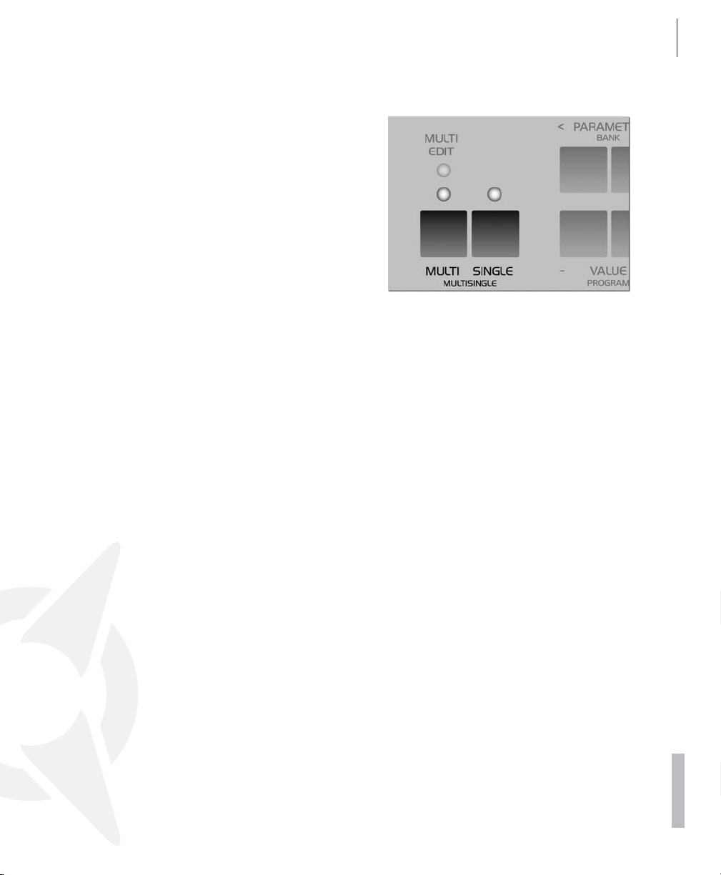
handling so much easier, is the ideal choice
when you’re working with a connected sequencer.
Please bear in mind that MULTI SINGLE mode
is really just another view of the normal MULTI
mode. MULTI SINGLE mode doesn’t offer a
unique data type for storing sounds, it always
works with the MULTI program currently selected in normal MULTI mode. All of the normal
MULTI mode parameters (keyboard zones, etc.)
remain intact and in force even though you
can’t view or vary them in MULTI SINGLE
mode. You can set the device to normal MULTI
mode at any time by pressing the MULTI button. To return to the MULTI SINGLE mode view,
simply press the MULTI and SINGLE buttons simultaneously.
When you’re working with a sequencer, start
with a MULTI program that features neutral settings for its ”administrative” parameters, for example, the MULTI program M0 Sequencer. Here
the PART numbers are identical to the MIDI
channels of the PARTs. Now when you work in
MULTI SINGLE mode, the Virus responds as if it
were in SINGLE mode, except that you have 16
sounds available simultaneously on 16 MIDI
channels. Use the PART buttons to select these
sounds.
ACCESS VIRUS RACK XL OS5 41
Operating Modes
The MULTI mode parameters feature a dedicated menu called the Multi Edit menu. Access it
by pressing the Multi button while the device is
in MULTI mode. The LED located over the MULTI button will light up to indicate that the Multi
Edit menu is active. Press the MULTI button
again to return to normal Play mode. If the device is in MULTI-SINGLE mode, press the MULTI and SINGLE buttons simultaneously to
access the Multi Edit menu. It suffices to press
either the MULTI or SINGLE button to return to
normal Play mode from MULTI-SINGLE mode.
You only need to exit MULTI SINGLE mode
when you want to store the MULTI program, for
example, to save the current global delay/reverb setting. In MULTI mode, these settings are
not stored along with SINGLE sounds.
In addition, you can activate another complete
MULTI program in MULTI mode only.
PDF VERSION - RESTRICTIONS APPLY
Page 42

42 CHAPTER 6
Concept and Operation
THE EDIT BUFFERS
Whenever you play or edit a SINGLE program,
its current data is stored in an edit buffer. This is
an individual memory slot for SINGLE programs
that has nothing to do with the memory slots in
the sound banks. When you activate a new
SINGLE, its data is copied to the edit buffer.
There you can edit it as you see fit while the
original remains unchanged in the bank. When
you activate STORE (more on this in a bit), the
content of the edit buffer is copied back to the
original slot in the bank (or, if you so desire, to
another memory slot).
In MULTI mode, you have one MULTI edit buffer
and 16 SINGLE edit buffers for the PARTs at
your disposal. When you activate another a
MULTI program, its data is copied from the
MULTI bank to the MULTI edit buffer. The MULTI program in turn contains address information
for the SINGLEs involved, in other words, the
bank and program numbers. These addresses
are also copied from the SINGLE banks into the
16 SINGLE edit buffers for the PARTs.
When you store a MULTI program, only the addresses of the SINGLE programs’ original slots
are saved, but not, however, the sound data in
the 16 SINGLE edit buffers. These must be
stored separately in the SINGLE program
banks.
In MULTI-Mode (or MULTI-SINGLE-Mode) the
same SINGLE-program can be recalled and edited on different parts. In this case all involved
EDIT-buffers contain variations of the same
original sound.
This type of edit buffer is used in most synthesizers; its advantages are many:
It lets you edit copies of sounds without sac-
rificing the original sounds.
Edit buffers can be stored in a sequencer and
sent from it to the Virus independently of the
sounds stored in the device. [“Dump - The
Sound in the Song” on page 140]
Page 43
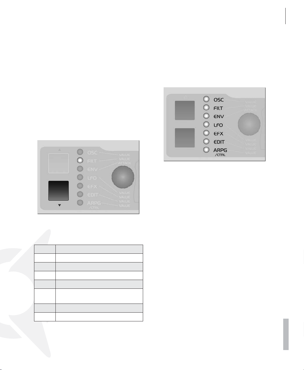
Operation
PARAMETER SELECTION AND DATA ENTRY
The parameters of the Virus rack XL are controlled via the five encoder knobs. The functions of
this row of knobs may be assigned to seven parameter groups that are indicated visually by
the seven LEDs located to the left of the encoders.
ACCESS VIRUS RACK XL OS5 43
Operating Modes
Select parameter groups by means of the two
vertically arrayed UP and DOWN buttons located next to the seven LEDs. The function of the
knobs corresponds to the respective label on
the selected parameter group and/or row.
The left knob is labeled "VALUE"; this is a special feature that requires some explanation:
Here's a brief explanation of the parameter
groups:
OSC The oscillator section
FILT The filter section
ENV The envelope section
LFO The LFO section
EFX The effect section
EDIT Here you'll find various peripheral
sound parameters
ARP The Arpeggiator section
CTL Organizational parameters
This knob is not labeled on the panel with a parameter name that indicates its purpose. Instead, the name of the parameter and its
function is shown in the display. Apart from the
envelope section, each of the parameter groups
features these peripheral parameters that are
grouped in menus. These are ancillary parameters that complement the directly accessible
parameters. They may be selected via the PARAMETER buttons and controlled via the aforementioned VALUE knob or the two VALUE
buttons.
In order to return to the current Play mode
(MULTI, SINGLE or MULTI-SINGLE), press the
MULTI or SINGLE button. Then you can switch
programs as usual via the VALUE buttons; the
VALUE knob is now disabled.
PDF VERSION - RESTRICTIONS APPLY
Page 44

44 CHAPTER 6
Concept and Operation
In Play mode, the other four knobs have the
same function as in the EDIT parameter group.
Accordingly, you can access Filter Cutoff, the
two Soft-Knobs and Master Volume directly.
If you want to return to the previously selected
parameter group or to the previously edited parameter, simply press the UP or DOWN button.
or buttons is indicated in the lower line. When
you select the LFO menu, you must also determine which LFO is to be controlled by the dedicated knobs. So if you want to use these
labeled knobs to control the functions LFO
Rate, Shape, Contour and Keyfollow for LFO 2,
you must use the PARAMETER buttons in the
display to dial in one of the parameters of LFO
2. This selected parameter may then be edited
via the VALUE knob. At the same time, you can
control LFO 2's Rate, Shape, Contour and Keyfollow via the four remaining knobs.
Once you've selected a parameter group or
section, the individual LEDs located next to the
knobs indicate whether or not the knobs are assigned a function in the currently active menu.
When you call up a parameter in the display
menus, you will also determining the function of
the dedicated knobs (those with the fixed labels). If, for example, you select the LFO section, then the menu of one of the three LFOs is
indicated in the upper line of the display. The
parameter that is controlled via the VALUE knob
This means that if, for example, you edit LFO 3
in the LFO section, then the parameters Rate,
Shape and Keyfollow are directly accessible as
is the case with LFO 2. However, LFO 3 does
not feature the Contour parameter. Consequently, the LED of the Contour knob will not
light up since the knob serves no function in
this situation.
If you press the PARAMETER buttons briefly,
you can scroll through the parameters contained in the selected display menu step by
step in the desired direction. If you press and
Page 45

ACCESS VIRUS RACK XL OS5 45
Operating Modes
hold one of the parameter buttons for a bit
longer, the display will automatically scroll
through the list of parameters in the given
menu. When you press and hold one PARAMETER button and then press the other PARAMETER button, the display will scroll through the
menu in parameter groups in the direction of
the button that you are holding down. This
handy feature lets you swiftly go from one parameter type to another, for instance, from all
chorus-related to all delay-related parameters.
If you also hold the second parameter button
down, the menus will automatically scroll in the
selected direction. Once you’ve scrolled to the
desired parameter group, simply select the desired parameter by pressing the button briefly.
You can also step through the parameters by
repeatedly pressing the same menu button.
The VALUE +/- buttons let you change the value
of the selected parameter in steps. When you
hold one of these buttons down, the value
changes automatically and the longer you hold
the button, the faster the pace of the value
change. You can increase this pace even further
by pressing and holding one VALUE button and
simultaneously pressing the other VALUE button. If you press and release both VALUE buttons simultaneously, the parameter is set to its
default value (mostly zero). This pertains to unipolar parameters (value range of 0 to 127) as
well as bipolar parameters (value range of -64
to +63).
Located next to some of these parameters,
you’ll see the abbreviations ”ENA” and ”DIS”.
The option ENA means enable and DIS means
disable.
The menus, particularly the EFFECTS menu,
contain parameter groups that are related by
virtue of their function, for instance, all parameters that are used to control the chorus. When
you switch the chorus off (CHORUS Dry/Eff =
OFF), all chorus parameters are of course irrelevant and will no longer appear in the menu. In
other words, when the chorus is disabled, you
can’t view its parameters. The reason for this is
to make menus clearer and less cluttered.
The triangular icon located next to the parameter value indicates in which direction you have
to change a value if you would like to reset the
parameter to the value that has been stored to
date. The previously stored parameter value as
well as the current value are displayed for parameters that feature a dedicated knob.
The Virus rack XL features numerous parameters. Many of these you can occasionally do
without because they are not absolutely essen-
PDF VERSION - RESTRICTIONS APPLY
Page 46

46 CHAPTER 6
Concept and Operation
tial to basic sound programming, and they do
tend to make the device a little more challenging to handle. EXPERT mode can solve this
problem. It lets hide and show rarely used parameters in the display menus. You'll find the
display for EXPERT mode in the ARP/CTRL
menu; it is the last parameter in the list. In the
chapter "The Parameters", those parameters
that belong to EXPERT mode are labeled [XP].
The MULTI mode parameters feature a dedicated menu called the Multi Edit menu. Access it
by pressing the Multi button while the device is
in MULTI mode. The LED located over the MULTI button will light up to indicate that the Multi
Edit menu is active. Press the MULTI button
again to return to normal Play mode. If the device is in MULTI-SINGLE mode, press the MULTI and SINGLE buttons simultaneously to
access the Multi Edit menu. It suffices to press
either the MULTI or SINGLE button to return to
normal Play mode from MULTI-SINGLE mode.
DISPLAY OF VALUES
When a menu is active, different display options
are available for parameters with a dedicated
knob. These can be selected under the menu
item KNOB DISPLAY in the CTRL menu:
- OFF Knob movements are not displayed; the
current contents of the display remain intact
when you turn a knob.
- ON The lower row of the display is being
overwritten by the parameter's value.
- SHORT When you turn a knob, the current
contents of the lower display line are briefly
overwritten by data representing the change
in parameter value; once the action is completed, the original contents reappear in the
lower display line.
- LONG Same as SHORT, except that - you
guessed it - the display shows the knob data
for a longer period of time.
- ON The contents of the display are overwritten when you turn a knob; the original menu
does not reappear in the display.
01111111111111111112
1 SYSTEM
KnobDispl Short≤
61111111111111111154
ALL ABOUT THE MEMORY
STORE
The mode structure of SINGLE, MULTI and
MULTI SINGLE MODE is mirrored in the STORE
functions: In SINGLE MODE, STORE saves the
current SINGLE PROGRAM; in MULTI MODE,
STORE saves the current MULTI PROGRAM;
and in MULTI SINGLE MODE, the SINGLE
PROGRAM of the current PART is stored.
The STORE process is always the same regardless of the operating mode: Press STORE. You
then gain access to the STORE menu. There
you can use the PARAMETER buttons to move
among the individual letters in the lower name
entry line and the number of the destined memory location as well as the bank number in the
upper line. Use the VALUE button to make entries. The term in the upper display line indicates the name of the memory location which
you will overwrite when you store the program.
Page 47

ACCESS VIRUS RACK XL OS5 47
Random Patch Generator
Once all of the entries correspond to the data
you have in mind, press STORE again to conclude the process and return to the previously
active operating mode of the Virus. If for whatever reason you change your mind and want to
cancel the operation, simply press SINGLE or
MULTI to return to the previous operating mode
without storing the program.
To belabor the point, when you store a
MULTI program, only the content of the MULTI
edit buffer is saved, not however the sound programs in the PARTs. These must be stored individually in MULTI SINGLE mode.
COMPARE
When you press STORE and then UP or DOWN,
you will activate Compare mode. After you have
programmed or edited a SINGLE sound, Compare mode lets you hear the unedited sound
that was originally stored in this memory slot.
Press UP or DOWN repeatedly to switch back
and forth between the Compare sound and the
edited sound so that you can - surprise, surprise – compare the two sounds. Use the PARAMETER/BANK buttons and the VALUE
buttons to step through the bank and program
numbers of the Compare sound. This lets you
search for a new memory slot for the edited
sound and, at the same time, hear the sound
that you will overwrite. The edited sound is not
modified or overwritten during this process.
Press STORE to do just that to the edited sound
– store it. Press MULTI or SINGLE to quit the
STORE process and/or exit Compare mode.
01111111111111111112
1 C126 -Init compare
61111111111111111154
If you want to store the SINGLE programs in the
PARTs to their original slots in the SINGLE
banks all at the same time, simply press STORE
and 1 C126 - Init
01111111111111111112
1 C126 - Init
[STORE] TO...
61111111111111111154
RANDOM PATCH GENERATOR
RANDOM PATCHES
The RANDOM PATCH GENERATOR can be
used to generate a new sound automatically or
a modify an existing sound at random. The PAR
DEPTH and AMOUNT parameters let you determine how radically the sound is changed. Depending on the values that you set here, the
RANDOM PATCH GENERATOR will do anything
PDF VERSION - RESTRICTIONS APPLY
Page 48

48 CHAPTER 6
Concept and Operation
from modifying sound parameters subtly to
morphing one sound into an entirely different
sound.
The RANDOM PATCH GENERATOR is activated
when you presses the button STORE while the
display is showing one of the two RANDOM parameters. The results of the computation are
stored in the Edit buffer and can be heard immediately. You can also press STORE several
times in order to create successive sound changes. If you want store a sound permanently that
the RANDOM PATCH GENERATOR has created, simply save it to a SINGLE memory slot in
the usual manner. For this purpose, press the
SINGLE button to activate PLAY mode (SINGLE
mode or MULTI-SINGLE mode) so that the
STORE button’s original function is restored.
If you want to restart the process with the original sound settings, simply return to PLAY mode
back and select the desired sound again.
PAR DEPTH
This parameter determines the number of
sound parameters that are influenced by the
RANDOM PATCH GENERATOR. If you enter a
low value for PAR DEPTH, just a few parameters will be modified. Beyond that, the manner
in which the few parameters are edited assures
that the sound is manipulated “organically”.
This simply means that it isn’t bent radically so
that, for example, the given sound can still be
played “tonally”.
As you increase the values for PAR DEPTH, other parameters that have a greater impact on the
timbre of the sound are changed. At higher values, the RANDOM PATCH GENERATOR tends
to generate noise-like sounds or special effects.
01111111111111111112
1 RANDOM [STORE]
ParaDepth 0≤
61111111111111111154
AMOUNT
This parameter determines the intensity of the
RANDOM PATCH GENERATOR’s effect on the
sound parameters. At lower values, sound
changes are fairly subtle, but you can intensify
the effect by repeatedly pressing the STORE
button. Higher values introduce fundamental
changes to the sound.
01111111111111111112
1 RANDOM [STORE]
Amount 0≤
61111111111111111154
Be aware that RANDOM PAR DEPTH and
RANDOM AMOUNT are not actual sound parameters. They merely set the parameters for the
RANDOM PATCH GENERATOR and only take
effect when the RANDOM PATCH GENERATOR
is activated. Not until then will the sound be
changed.
Page 49

ACCESS VIRUS RACK XL OS5 49
Modmatrix And Soft Knobs
MODMATRIX AND SOFT
KNOBS
CREATING MODULATIONS VIA ASSIGN
As a rule, it is of course desirable to be able to
create modulation routing configurations on a
synthesizer. In other words, you want to enjoy
the freedom to combine different modulation
sources and destinations as you see fit. Sometimes you may come up with ideas for standard
modulations that the ”hard-wired” factory modulation routing options simply can’t satisfy. This
is why we opted to equip the Virus with a versatile Modulation Matrix – you’re sure to find it a
welcome addition. On the Virus, you can create
modulation routing configurations freely as you
see fit using ASSIGN options. They are located
in the EDIT menu, where they appear under the
name of – you guessed it – ASSIGN).
The three ASSIGN options let you control up to
six modulation destinations via up to three
modulation sources. Simply go to ASSIGN, select one of the modulation sources (SOURCE)
and one or several modulation destinations
(DESTINATION). Each of these configurations
features a parameter that determines modulation intensity (AMOUNT). ASSIGN 1 can control
one modulation destination, ASSIGN 2 can
control two and ASSIGN 3 can control three
modulation destinations, each with independent AMOUNTs.
These ASSIGN options serve several purposes:
for one, they let you assign an external MIDI
controller, for example, the keyboard’s modulation wheel, to the desired parameter. You can
also chose to use the sound generator’s internal
modulators, such as LFOs and envelopes, as
modulation sources. The control range of the
source may be limited via the AMOUNT values
or inverted so that the modulation occurs strictly within the desired value range for the target
parameter. For your target parameters, you can
chose from among virtually all sound parameters that feature an infinitely variable control
range – ergo, you have more than 100 modulation destinations at your disposal! Since the
sources and destinations may be selected independently, you may even modulate a single parameter by using up to three modulation
sources simultaneously. For this purpose, the
control signals of the modulation sources are
added up or overlapped. Conversely, you can
also modulate up to six parameters with just
one controller, which gives you all kinds of sophisticated sound morphing options. For this
purpose, select the same source for all three
ASSIGN options so that it modulates all six
possible destinations. This lets you radically reshape sounds and even transform or morph
them into entirely different sounds.
01111111111111111112
1 ASSIGN
Source OFF≤
61111111111111111154
You’ll find a list of available sources and
DESTINATIONS in the appendix. [“Appendix”
on page 157]
SOFT KNOBS
The Virus is equipped with two knobs that, rather than being dedicated to predefined tasks,
may be assigned to different parameters by
you, the user. This option is quite handy, for it
lets you control directly the many menu parameters that do not feature a dedicated knob.
PDF VERSION - RESTRICTIONS APPLY
Page 50
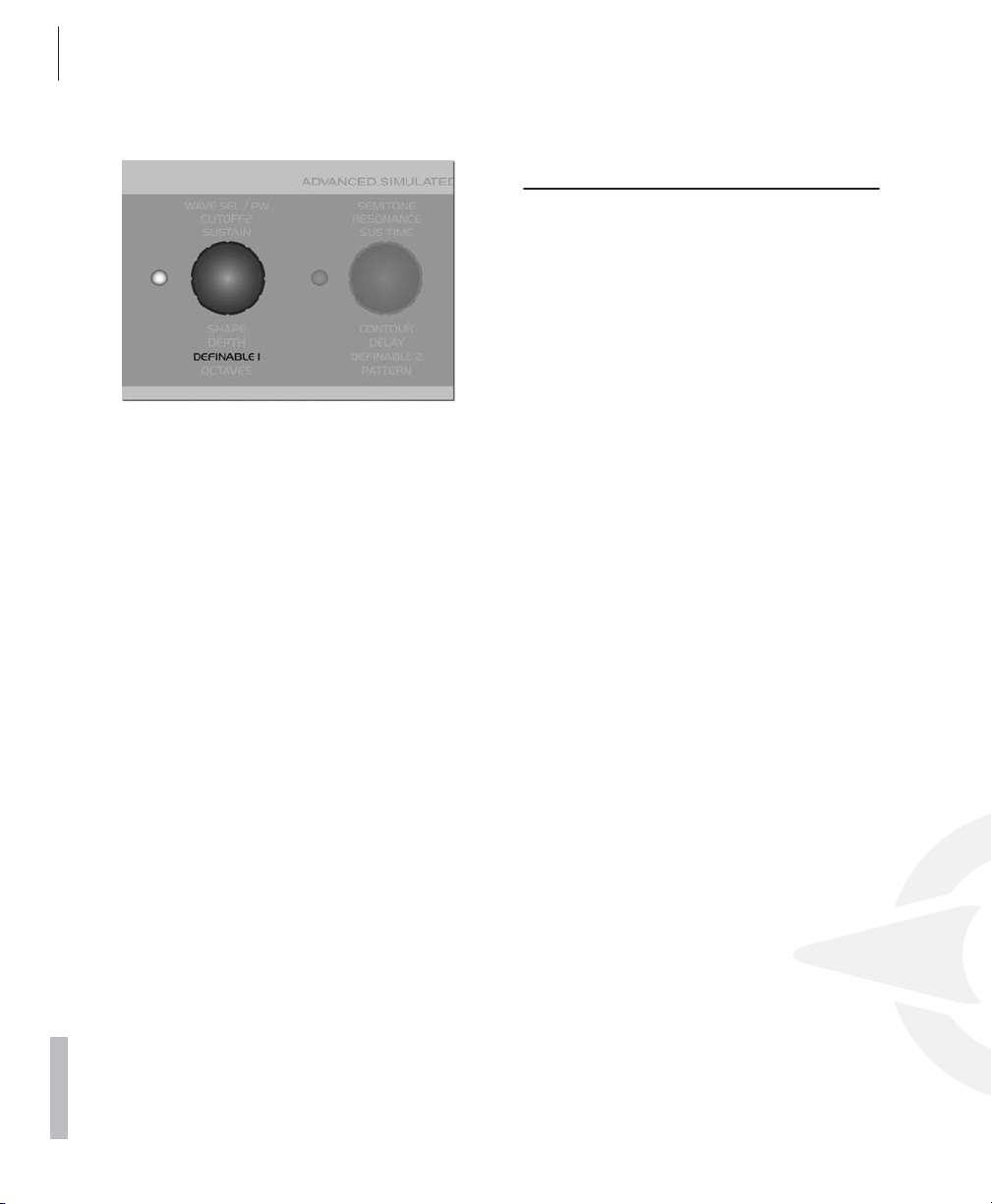
50 CHAPTER 6
Concept and Operation
These Soft-Knobs operate in three different
modes:
- GLOBAL The knob controls the parameter
that you have set to Global in the Soft Knob
menu regardless of what the other settings
and the selected SINGLE program may be.
- SINGLE The knob controls the parameter
that you have set to Single in the Soft Knob
menu. The setting for this parameter is stored
in the SINGLE program and called up whenever you select this program. If, however, you
have not selected a parameter for this program (Soft Knob Single = OFF), the setting for
Soft Knob Global is automatically enabled.
The setting for the actual Soft Knob mode is
global. Under normal circumstances, you
should set Soft Knob mode to ”Single” because
this is the most versatile mode. When you select a SINGLE sound whose Soft Knob mode is
set to ”Single”, this setting is of course enabled. If not, Global Soft Knob mode is enabled.
01111111111111111112
61111111111111111154
1 Soft Knob 1
Mode Single≤
MASTER CLOCK AND MIDI-
CLOCK
The Virus is equipped with a global clock generator that lets you sync the LFOs, arpeggiators
and delay up to a common song tempo and
rhythm. The clock generator works either internally with a freely variable speed or it can, in
turn, by synced up to the MIDI clock of an external sequencer. This synchronization occurs
automatically when the device receives a MIDI
clock signal via its MIDI In. You can vary the
speed of the clock generator within a range of
63 to 190 BPM (beats per minute) via CLOCK
TEMPO. When the device is synchronized via
MIDI clock, the clock generator automatically
accepts the speed dictated by the connected
sequencer; the internal tempo setting is in this
case meaningless and thus disabled. The individual sections of the Virus are synced up to the
clock generator at rhythmic intervals such as 1/
16, 1/4 and so forth. These values may be assigned individually for every section. (ARPEGGIATOR CLOCK, CLOCK LFO 1, CLOCK
LFO 2, CLOCK LFO 3, DELAY CLOCK, see the
respective sections).
In SINGLE MODE, CLOCK TEMPO pertains to
the current SINGLE PROGRAM and is stored
along with it. In MULTI MODE, the CLOCK
TEMPO settings for the involved SINGLE PROGRAMs are ignored. Instead, all involved SINGLE PROGRAMs are controlled via the same
clock generator. Its CLOCK TEMPO is saved in
the MULTI PROGRAM (as are the settings for
the global delay effect).
This feature lets you control the LFOs and arpeggiators of several MULTI PARTS in a common rhythmic context.
A “c” symbol will appear in the display
Page 51

ACCESS VIRUS RACK XL OS5 51
The Effects Section
When the Virus is receiving MIDI Clock data.
If you’re sure you do NOT want the device to be
synchronized automatically to MIDI clock, set
MIDI CLOCK RX to Off (in the CTRL menu).) To
avoid confusion, please keep in mind that MIDI
Clock is not the same thing as MIDI Time Code.
The latter doesn’t deal with tempo at all but with
time-related information structured in hours,
minutes, seconds, etc. which is of no benefit to
you in this context.
THE EFFECTS SECTION
For every SINGLE program and every PART,
you can access two stereo effects individually.
You’ll find these effects – analog boost and
chorus – in the aptly named EFFECTS menu.
The vocoder and the delay/reverb section are
each available just once, but you can address
them individually via the PARTs’ Effect Send parameter. In the signal path, all effects are connected in series in accordance with their
sequence in the Effects menu.
Each SINGLE program contains its own settings for the delay/reverb section. In MULTI
mode, the sound programs involved share the
same delay/reverb section. For this reason, the
parameter values are determined by the settings of the currently active MULTI program.
[“The Multi Mode Parameters” on page 113].
AUDIO INPUTS
You can also opt to use external audio signals
in place of the on-board oscillators for the
sound programs or MULTI PARTs. The Virus is
equipped with two inputs for external signals.
You can route these to its sound generating
components (the filters, the saturation stage as
well as the volume and panorama stage) or
patch them directly to the effects section of the
Virus. External audio signals may also be used
as carrier or modulator signals for the vocoder.
Any PART that you use to process an external
audio signal in MULTI mode can, like every other PART, be routed freely to one or two of the
four audio outputs.
The Virus rack XL is equipped with two audio
inputs on the back panel. Additionally the left
input is accessible on the front panel. When you
plug a cord into the front input, the rear left input is disabled.
As a rule, when you’re processing external audio signals, you need to distinguish between
the following two operating modes:
- DYNAMIC To make external signals audible
in this operating mode, the volume envelope
must be triggered via a note. This option, for
example, lets you create typical gater effects.
INPUT Dynamic mode is also polyphonic. If
you set the KEYFOLLOW value for the filters
to 100%, the resonant frequencies of the filters and oscillators can be played in a tempered manner via the INPUT signal. This lets
you play entire chords as well as arpeggiator
lines using the filters. The noise generator is
also active in INPUT mode.
- STATIC In Input Static mode, the external
audio signals are audible via the output without having to trigger a note. Bear in mind that
the oscillators as well as all functions that
have to do with trigger and pitch are disabled
PDF VERSION - RESTRICTIONS APPLY
Page 52

52 CHAPTER 6
Concept and Operation
(envelopes, LFO Env mode, Keyfollow...) In
INPUT Static mode. When you set the device
to this mode, one voice of the Virus is activated automatically. If you select a stereo source
(L+R) for INPUT Select, two voices are activated much like in UNISON mode: Twin. In
this case, you can also use the UNISON Pan
Spread parameter to determine the basic
width of the panorama and UNISON LFO
Phase to shift the LFO phase position between the voices.
- TOEFFECTS An alternative to INPUT Static
mode, here the audio signal is routed directly
to the effects section of the SINGLE program
or PART. This mode doesn’t use the voices of
the Virus, which means that its polyphonic
performance remains fully intact and available. The filter section is unavailable in this
mode.
01111111111111111112
1 INPUT
Mode Dynamic≤
61111111111111111154
OSC VOLUME / INPUT
When one of the two INPUT modes is activated,
the OSC VOL parameter rather than the oscillators controls the level of the INPUT signal in
front of the Filter section and of course also the
gain of the SATURATION stage. In INPUT Dynamic mode, the level increases quite rapidly
when you play several voices polyphonically.
The reason for this is that – in contrast to when
you’re dealing with several oscillator signals –
the voices are correlated because they are receiving an identical input signal. In the event
that the Virus generates distortion when you’re
dealing with this type of signal routing set-up,
be sure to back off the input level a tad via the
OSC VOL knob.
INPUT GLOBAL SETTINGS
In the Input menu, you'll find a gain switch (INPUT Gain) that increases the input signal by 20
decibels before it is sent to the digital analog
converter. This means that with the proper
cords you can connect a microphone, an electric guitar or a record player directly to the Virus
rack XL. However, to attain the best possible
sound quality, it is advisable to patch the signal
into an appropriate signal processor such as a
microphone preamplifier, a mixer, or a guitar
preamp before you route it into the input of the
Virus. Please turn down the Master Volume
knob before you turn input gain up. Be aware
that boosting the signal by 20 decibels increases the level tenfold!
Additionally the Virus is equipped with an amplifier stage (INPUT Boost), that can boost the signal level of the two inputs continuously by up to
36 dB. The signal is boosted in the digital section of the Virus, so the noise level of the analog-digital converters increases automatically.
Consequently you should dial in the cleanest,
loudest possible signals at the external sound
generator, or use the INPUT Gain switch.
Since record players have a characteristic frequency response, we equipped the Virus rack
XL with a suitable Phono equalizer. It may be
activated via the "INPUT Phono" parameter.
INPUT LEVEL INDICATOR
Alternatively, the RATE LEDs of LFO 1 and 2
can also serve as level indicators for the left and
right external audio inputs. The Virus automatically switches to this level indicator mode when
the selected SINGLE program accesses the external audio inputs. The LEDs will flash rapidly
to indicate that the inputs are being overloaded.
You should dial in the proper level on the device
that is sending the analog signals. The reason
for that you want to feed the highest possible
Page 53
ACCESS VIRUS RACK XL OS5 53
Audio Routing
clean signal level to the analog-to-digital converters of the Virus so that they will deliver the
best possible performance. [“LED MODE” on
page 128]
AUDIO ROUTING
This is why, for example, the delay effect of a
PART that is routed to the pair of outputs labeled OUT 2 will still be audible on OUT 1. This
can be desirable yet may also lead to confusion. To encourage the former and prevent the
latter, set the Effect Send parameter of the
PART to zero when you’re using individual outputs.
In MULTI mode, the delay/reverb section feature its own OUTPUT Select that is independent
of the PARTs.
SOUND CATEGORIES
The Virus gives you the option of classing the
stored SINGLE sounds in categories. With the
benefit of these categories, you’ll be able to find
a desired sound much faster.
You have the following categories at your disposal:
THE AUDIO OUTPUTS
In MULTI mode, you can choose a mono or
stereo audio output in the OUTPUT Select
menu independently for every PART.
In contrast to the majority of other effects, the
delay/reverb section is not available individually
for each PART. Instead, it processes the signals
of the PARTs collectively. You can, however,
control the intensity of the effect individually for
each PART using the respective Effect Send parameter. Consequently, the delay/reverb section
has just one signal output, which cannot be distributed to the outputs of the individual PARTs.
Off, Lead, Bass, Pad, Decay, Plug, Acid, Classic, Arpeggiator, Effects, Drums, Percussion, Input, Vocoder, Favourite ...
Every SINGLE sound can be assigned to up to
two categories by means of the parameters
CATEGORY 1 and CATEGORY 2. For example,
you could assign the attributes "Bass" and "Acid" or "Lead" and "Favorite 1" to a given sound.
These categories may be changed at any time
and can be stored along with the sound. The
factory sounds are assigned default categories.
Once you’ve assigned categories, you can
search for the sounds within a specific category
in SINGLE mode and MULTI-SINGLE mode:
PDF VERSION - RESTRICTIONS APPLY
Page 54

54 CHAPTER 6
Concept and Operation
Press and hold the SINGLE button, then use the
PARAMETER buttons to select the category in
which you want to search for sounds. Hold the
SINGLE button down and use the VALUE buttons to select sounds that are assigned to the
currently selected category. It doesn’t matter if
this sound has been assigned to the category
via CATEGORY 1 or CATEGORY 2; in either
case, it will show up in the list. While you’re selecting sounds, SINGLEs that don’t belong to
the currently selected category are simply
skipped over when you hold the SINGLE button
down.
ADDITIONAL FUNCTIONS
PANIC FUNCTION
The Virus features a Panic function to remedy
stuck notes caused by MIDI transmission parity
errors and the like. When you press the POWER
and the STORE button simultaneously, then all
voices of the Virus that are still sounding will be
released.
AUDITION FUNCTION
On the Virus panel, you can trigger notes without using a keyboard. When you press the UP
and DOWN buttons simultaneously, the Virus
will play the note C3. If you hold the buttons
down for longer than a second, the note will
continue to sound after you release the buttons.
A double-click on both buttons initiates a controller reset. The various voices that are still
sounding will be cut off instantly and controllers
such as the modulation wheel, channel volume
and pitch bender are reset to the default settings.
RESET FUNCTION
If you get the impression that the VIRUS is behaving unstable or indeed strange, we suggest
you perform a system reset. Holding the PA-
Page 55

RAMETER LEFT button while switching the VIRUS on, performs a system reset. No data will
be lost during this procedure, although some
global system settings as ”Global Channel” will
be reset.
ACCESS VIRUS RACK XL OS5 55
Additional Functions
PDF VERSION - RESTRICTIONS APPLY
Page 56

56 CHAPTER 6
Concept and Operation
Page 57

The Parameters
Page 58

58 CHAPTER 7
The Parameters
OSC Section (Encoder)
OSCILLATOR 1
The following section lists all parameters in the
Virus, each with a brief definition or explanation.
The function of the Encoders depends on the
selected section and the currently active display menu. If the given Encoder does not have
an assignment, the corresponding LED on the
front panel will extinguish. If no menu is activated (none of the seven section LEDs is illuminated) the Encoder assignments are determined by
the Edit section.
SHAPE
This control feature lets you determine the
waveshape for the WAVE section (one of 64
variable spectral waveshapes). The waveshape
is infinitely variable from sawtooth through to
pulse waves. Wave or pulse width selection is
executed via the SHAPE and WAVE SEL/PW
control features (see appropriate section): If
SHAPE has a value less than the value of the
“center position”, then WAVE SEL/PW determines the waveshape; if the SHAPE value is
higher than that of the center position, then
WAVE SEL/PW determines the pulse width.
WAVE SEL/PW
has two functions, depending on the SHAPE
(see appropriate section) value:
When SHAPE has a value lower than that of
the “center position”, then WAVE SEL/PW lets
you select from the 64 spectral waveshapes
available in the ROM of the Virus. Waveshape 1
is a sine wave; No. 2 a triangle, the remainder of
the waves feature different combinations of frequencies.
When the SHAPE value is higher than that of
the “center position”, then WAVE SEL/PW determines the pulse width: At the far left position
the pulse width is 50%, at the far right it is 0%,
which means the wave no longer oscillates.
SEMITONE
Determines the interval between the second oscillator and the first oscillator: Control range +/48 semitones, assigned in semitone steps.
OSCILLATOR 2
SHAPE
Same as OSCILLATOR 1; see paragraph above.
WAVE SEL/PW
Same as OSCILLATOR 1; see paragraph above.
Page 59
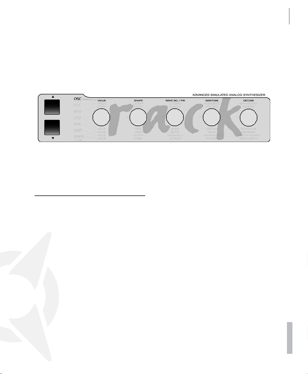
ACCESS VIRUS RACK XL OS5 59
Oscillator 3
SEMITONE
Same as OSCILLATOR 1; see paragraph above.
OSCILLATOR 3
OSCILLATOR-3 SEMITONE
Transposes Oscillator 3 in semitone steps. Control range: +/-4 octaves. (Not available if OSCILLATOR 3 MODE = “OFF” or “SLAVE”.)
01111111111111111112
1 OSCILLATOR 3
Semitones +0≤
61111111111111111154
DETUNE
Detunes the second oscillator relatively to the
first. With this parameter, you can dial in everything from slight deviations in pitch to major
fluctuations between the two oscillators.
OSCILLATOR-3 DETUNE
Detunes the third oscillator relatively to the first.
With this parameter, you can dial in everything
from slight deviations in pitch to major fluctuations relatively to the other oscillators.
01111111111111111112
1 OSCILLATOR 3
Detune +0≤
61111111111111111154
PDF VERSION - RESTRICTIONS APPLY
Page 60

60 CHAPTER 7
The Parameters
SUB OSCILLATOR
VOLUME
Determines the volume level of the SubOscillator.
01111111111111111112
61111111111111111154
SHAPE
Switches the waveshape of the SubOscillator
between SQUARE and TRIANGLE.
01111111111111111112
61111111111111111154
1 SUBOSCILLATOR
Volume 30≤
1 SUBOSCILLATOR
Shape Square≤
Page 61

OSC Sektion (Menu)
OSCILLATOR 1
ACCESS VIRUS RACK XL OS5 61
Oscillator 1
scale); at 0 the keyboard control option is off.
Negative values generate opposite control intensities.
01111111111111111112
1 OSCILLATOR1
Keyfollow +32≤
61111111111111111154
WAVE
Selects among of 64 spectral waveshapes. This
parameter is identical to WAVE SEL/PW (see
appropriate section) when SHAPE (see appropriate section) is set to the left half of its control
range. However, in contrast to WAVE SEL/PW,
WAVE is always available regardless of the current SHAPE setting.
01111111111111111112
1 OSCILLATOR1
Wave Sin≤
61111111111111111154
KEY FOLLOW
Determines the intensity of the pitch control via
the keyboard: At the value +32 (standard setting) the oscillator is controlled normally, i.e. the
octave you are playing is identical to the oscillator octave; at +63 every ascending octave you
play transposes the oscillator upwards by two
octaves (whole note scale); +15 transposes the
oscillator upwards by one octave for every two
ascending octaves you play (quarter note
OSCILLATOR 2
WAVE
Same as OSCILLATOR 1; see paragraph above.
SYNC
Synchronizes the second oscillator with the
first: The SYNC function forces Oscillator 2 to
interrupt its wave cycle and restart it at the
same time as Oscillator 1 starts its cycle. The
effect of this measure is that pitch deviations
and intervals are no longer audible as such;
what you hear are tonal modifications: Repeated interruption of the Oscillator 2 wave cycle
generates new tonal spectra with a great deal of
overtone content. The tone of a given spectrum
can be influenced via the SEMITONE knob,
among other control features.
01111111111111111112
1 OSCILLATOR2
Sync ON≤
61111111111111111154
PDF VERSION - RESTRICTIONS APPLY
Page 62

62 CHAPTER 7
The Parameters
FM AMOUNT
Controls the frequency modulation intensity of
the second oscillator by the first. Depending on
the selected FM AMOUNT and the interval between the oscillators, the frequency modulation
generates everything from slightly to radically
enriched spectra. In the Virus you have the option of combining the two functions called oscillator synchronization (SYNC) and frequency
modulation (FM AMOUNT) to generate new harmonic spectra. The characteristics of the frequency modulation can be modified with the
FM Mode parameter (in the OSCILLATOR EDIT
menu). You may also select an external audio
signal and have Oscillator 2 modulate its frequency.
01111111111111111112
1 OSCILLATOR2
FmAmt 22≤
61111111111111111154
FM MODE
Oscillator 2’s frequency modulation can be executed in a variety of ways using a different signal or modulation sources. You can also select
an external audio signal for frequency modulation. Set the intensity of the modulation via the
FM AMOUNT knob. Choose the sine wave for
Oscillator 2 in order to achieve the most transparent form of frequency modulation. Here’s a
look at the FM sources that you have at your
disposal:
01111111111111111112
1 OSCILLATOR 2
FmMode PosTri≤
61111111111111111154
- TRI Linear FM with a bipolar triangle generated by Osc1.
- WAVE The selected Osc1 wave is the FM
source. This lets you in some cases create
typical DX7-FM sounds (here OSCILLATOR 1
SHAPE should be set to WAVE).
- NOISE The noise generator is the FM source
(see also NOISE Color). Excellent for drum
sounds.
- INPUT Here the mono or stereo signal from
external analog inputs or from an internal aux
bus may be routed to the frequency modulation. The input FM is in real stereo, even in
connection with UNISON mode.
KEYFOLLOW
Same as OSCILLATOR 1; see paragraph
above.
FILT ENV -> PITCH
This parameter determines the intensity at
which the filter envelope controls the pitch of
the second oscillator (PITCH OSC 2).
01111111111111111112
1 OSCILLATOR2
FltEnv~Ptch +0≤
61111111111111111154
FILT ENV -> FM
It determines the intensity at which the filter envelope controls the frequency modulation (FM
AMOUNT). This as well as the previous parameter are ”relics” from the predecessor model of
- POSTRI One-way FM with a positive triangle
generated by Osc1.
Page 63

ACCESS VIRUS RACK XL OS5 63
Oscillator 3
the Virus. Modulations such as these may also
be implemented via the Modulation Matrix (see
the section ”ASSIGN” below).
01111111111111111112
1 OSCILLATOR2
FltEnv~Fm +0≤
61111111111111111154
OSCILLATOR 3
MODE
The VIRUS offers a third master oscillator per
voice that you can activate whenever you need
it. It lets you come up with even more complex
sounds by adding more oscillations and spectra
to the signal. When Oscillator 3 is switched on,
(i.e. OSCILLATOR 3 mode is not set to the OFF
position), the polyphony of the VIRUS decreases by up to six voices, depending on how many
voices use the third oscillator in MULTI mode.
01111111111111111112
1 OSCILLATOR 3
Mode Off≤
61111111111111111154
The second position of OSCILLATOR 3 mode is
called SLAVE. Here Oscillator 3 is active, but –
just like when it is set to the OFF position – no
further parameters are available and visible. In
this operating mode, Oscillator 3 is the ”twin” of
Oscillator 2. It adds further oscillations, thus
making the sound fatter and more animated.
Oscillator 2 and 3 are handled collectively using
Oscillator 2’s control features just as if the two
were a single oscillator. All settings that you dial
in for Oscillator 2 apply to Oscillator 3, with one
exception – DETUNE. This parameter runs
counter to that of Oscillator 2.
You can select the waveshapes individually for
Oscillator 3 via the following OSCILLATOR 3
mode options: sawtooth, square (pulse width
modulation), sine, triangle and all further spectral waveshapes. You have three further parameters available once you set Oscillator 3 to an
individual waveshape. These are explained further below. All other parameters as well as the
settings for the oscillator modulations (LFO
pulse width modulation and so forth) are dictated by Oscillator 2. This doesn’t limit the functionality of the third oscillator by much (if at all),
but it certainly facilitates intuitive handling. The
FM, Sync and Ring Modulator functions are not
available for the third oscillator.
Like all other oscillators, the level of Oscillator 3
is controlled via OSCVOL.
VOLUME
The individual volume level of oscillator 3. Additionally the level is controlled by OSC VOL. (Not
available if OSCILLATOR 3 MODE = “OFF” or
“SLAVE”.)
01111111111111111112
1 OSCILLATOR 3
Volume 64≤
61111111111111111154
PDF VERSION - RESTRICTIONS APPLY
Page 64

64 CHAPTER 7
The Parameters
OSCILLATORS
OSC BAL
Determines the balance between the Oscillators
1 and 2 volume level.
01111111111111111112
1 OSCILLATORS
Balance 64≤
61111111111111111154
VOLUME
This knob has two functions:
In the left half of its control range up to the
center position (MIDI value 64), OSC VOL determines the master volume of the three oscillators
prior to the filter section input. The Noise Generator and the Ringmodulator are not affected
by the master volume knob OSC VOL. Their level is controlled separately in the OSCILLATOR
EDIT menu (see appropriate section).
In the right half of the control range from the
center position to the far right, OSC VOL increases the saturation intensity (Gain) for the input of the SATURATION stage (see appropriate
section); however this adjustment is compensated post-SATURATION stage so that when
you adjust the gain you are not actually increasing the volume, only manipulating the tonal
spectrum in terms of saturation. The intensity of
the remaining DSP effects available in the SAT-
URATION Stage is controlled via the OSC VOL
knob.
PHASE INIT
This feature lets you select the oscillator phase
position at the start of a note. At a value of 0, all
oscillators oscillate freely much like in a traditional analog synthesizer. At values of 1 and
higher, Oscillator 1 starts the note with a phase
angle of 0, whereas the phase position of the
second oscillator is shifted increasingly at ascending values. The Phase position of oscillator
3 is shifted to the opposite direction. With this
parameter, the attack phase of every note is
identical, which is a handy feature for programming drums and percussive sounds. In conjunction with Oscillator 3 and PHASE INIT, you
can create prominent overtones that are initiated at the beginning of a note.
01111111111111111112
1 OSCILLATORS
PhaseInit Off≤
61111111111111111154
RINGMODULATOR
VOLUME
The ring modulator multiplies the output of both
oscillator 1 and 2 to create interesting sounds
with rich enharmonic overtones. These overtones are highly dependent on the frequency
coherence of both oscillators and it’s waveforms. The frequency coherence can be
changed, for instance use the OSC2 SEMITONE parameter. If the RINGMODULATOR
VOLUME is zero, the ring modulator is switched
off. OSC VOL does NOT affect the ring modula-
Page 65

tor level. Therefore the original oscillator signal
can be levelled independently of the ring modulator.
01111111111111111112
1 RINGMODULATOR
Volume 0≤
61111111111111111154
NOISE
NOISE VOLUME
The volume of the noise generator. As with the
ring modulator, the volume is idependent off the
OSC VOL parameter.
ACCESS VIRUS RACK XL OS5 65
Noise
COLOR
Determines the sound of the Noise. Positive values emphasis on high frequencies, negative
values on the bass frequencies.
- MIDDLE Neutral (white noise, all frequen-
cies are emphasised equally).
- NEGATIVE Lowpass (pink noise, dark and
emphasised on bass frequencies).
- POSITIVE Highpass (bright and thin noise,
emphasised on high frequencies).
01111111111111111112
1 NOISE
Color +0≤
61111111111111111154
PDF VERSION - RESTRICTIONS APPLY
Page 66
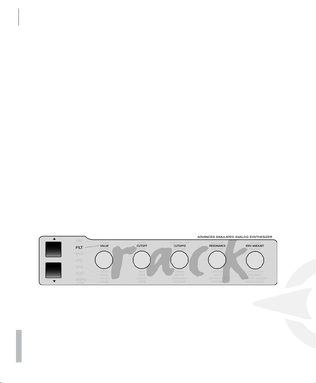
66 CHAPTER 7
The Parameters
Filter Section (Encoder)
CUTOFF
Determines the cutoff frequency of Filter-1 and
2 (with exceptions; see CUTOFF 2).
LINK ON/OFF to sever the link between CUTOFF and CUTOFF 2. In this case the two knobs
CUTOFF and CUTOFF 2 are independent cutoff
controls for Filters 1 and 2, respectively.
RESONANCE
Controls the resonance (also called filter feedback or Q factor). Depending on the FILT SELECT setting, RESONANCE affects the first
filter, the second filter or both filters.
CUTOFF 2 (OFFSET)
Controls the cutoff frequency of Filter-2. Normally, CUTOFF 2 does not operate absolutely,
but relatively to CUTOFF: The cutoff frequency
of the second filter is subordinate to the CUTOFF value you determined for the first filter.
However you can use the CUTOFF 2 knob to
dial in a relative +/- deviation in frequencies, i.e.
a higher or lower frequency (OFFSET). When
you set CUTOFF 2 to the center position, both
filters have the same CUTOFF frequency. In
FILTER EDIT Menu, you can access CUTOFF
ENV AMOUNT
Determines the modulation intensity of the cutoff frequency filter envelope. Depending on the
FILT SELECT setting, ENV AMOUNT affects the
first filter, the second filter or both filters. In contrast to virtually all other modulation intensity
parameters in the Virus, ENV AMOUNT is a unipolar parameter. The polarity of the modulation
can be changed individually for each filter via
the ENV POLARITY function in the FILTER EDIT
menu.
Page 67

Filter Section/ Menu
FILTER 1
KEY FOLLOW
Determines the extent to which the filter frequency follows the pitch (Note Number) and the
Pitch Bend. The function uses C 1 (MIDI Note
Number 36) as a neutral starting point or base
note: Regardless of the KEY FOLLOW value,
the filter frequency is not influenced at this
pitch. In the FILTER EDIT menu you have the
option of freely defining the base note under
Keyfollow BASE.
01111111111111111112
1 FILTER1
Keyfollow +32≤
61111111111111111154
FILT 1 MODE
Selects the operating mode of the indicated filter:
ACCESS VIRUS RACK XL OS5 67
Filter 1
- HIGHPASS The high pass filter works in the
opposite manner of the low pass filter: It suppresses the lower frequencies in a signal and
lets the higher frequencies pass.
- BANDPASS The band pass filter suppresses
both ends of the tonal spectrum and allows
only a narrowly defined bandwidth of the
original sound to pass.
- BANDSTOP The band stop filter, band reject
filter or notch filter works in the opposite
manner of the bandpass filter. It allows all of
the frequencies of a signal except for a narrow frequency band around the cutoff to
pass. The term “notch” is fairly descriptive;
you might say this filter chops a notch out of
the sound spectrum.
01111111111111111112
1 FILTER1
Mode Lowpass≤
61111111111111111154
ENV POLARITY
Switches back and forth between positive
(POS) and negative (NEG) ENV AMOUNTs for
Filter-1 (see appropriate section).
01111111111111111112
1 FILTER1
EnvPolarity Pos≤
61111111111111111154
- LOWPASS The low pass filter suppresses
frequencies higher than the CUTOFF frequency (see appropriate section) and allows the
lower frequencies through.
PDF VERSION - RESTRICTIONS APPLY
Page 68

68 CHAPTER 7
The Parameters
FILTER 2
KEY FOLLOW
same as FILTER 1
MODE
same as FILTER 1
ENV POLARITY
Switches back and forth between positive
(POS) and negative (NEG) ENV AMOUNTs for
Filter-2 (see appropriate section).
01111111111111111112
1 FILTER2
EnvPolarity Pos≤
61111111111111111154
CUTOFF LINK
Switches the knob and the parameter CUTOFF
2 (see appropriate section) back and forth between two operating modes:
- ON In this mode, CUTOFF 2 operates relatively to the CUTOFF knob value rather than
absolutely (OFFSET): The cutoff frequency of
the second filter is - like the first filter - determined by the CUTOFF value. However you
can dial in an offset (relative ascending or descending deviation) of the frequency via the
CUTOFF 2 knob. At the center position (12
o’clock) of CUTOFF 2, the frequencies of the
two filters are identical.
- OFF Now,the CUTOFF and CUTOFF 2 knobs
are no longer linked and CUTOFF 2 operates
absolutely in a control range of 0 to 127. In
this case the CUTOFF and CUTOFF 2 knobs
are two independent control features that determine the respective cutoff frequencies for
Filter-1 and 2. CUTOFF LINK pertains exclusively to the CUTOFF 2 knob and the corresponding parameter. CUTOFF 2 has no
influence on the other parameters of the second filter.
01111111111111111112
1 FILTER2
CutoffLink On≤
61111111111111111154
FILTERS
BALANCE
Has different functions depending on the FILTER ROUTING setting (see appropriate section
as well): In the parallel FILTER ROUTING operating modes PAR 4 and SPLIT, it controls the
balance of volume levels between the two filters
- or in actuality SATURATION and Filter-2.
Technically, in the serial FILTER ROUTING operating modes SER 4 and SER 6, the left half and
the right half of the control range address different parameters: When the knob is set to the far
left position, you will hear Filter-1/Saturation exclusively, whereas Filter-2 is blended into the
mix as you rotate the knob towards the center
position. When the knob is set to the far right
position, you will hear Filter-2 exclusively,
Page 69

ACCESS VIRUS RACK XL OS5 69
Filters
whereas Filter-1/Saturation is blended into the
mix as you rotate the knob towards the center
position.
Consequently, you must set FILTER BALANCE
to the center position if you want both filters in
series (in equal amounts) in the signal path.
01111111111111111112
1 FILTERS
Balance +10≤
61111111111111111154
ROUTING
This feature offers four filter routing options
which allow you to operate the filters in series
or in parallel:
- SER-4 The filters are switched in series; with
two poles each (12dB), both filters have the
same slope for a total of four filter poles
(24dB).
- SER-6 The filters are switched in series; Filter-1 has four poles (24dB), Filter-2 has two
poles (12dB) so the overall slope is equivalent
to six poles (36dB).
- PAR-4 The filters are switched in parallel and
feature two poles each (12dB).
- SPLIT The filters are switched in parallel and
feature two poles each (12dB). Additionally,
they receive independent input signal s (more
on this later). The stereo position of the signals can also be manipulated via the parameter TWIN MODE PAN SPREAD (see
appropriate section) in the EDIT menu.
SELECT
This control feature is used to allocate the two
knobs RESONANCE and ENV AMOUNT to the
first filter, second filter or both filters. The currently active assignments are indicated by the
integrated LEDs. To control both filters simultaneously via the knobs, you must first press both
buttons simultaneously. SELECT pertains to the
corresponding knob located on the Virus only,
but not to the sound parameters it controls.
These parameters exist separately in both filters regardless of the SELECT setting. This is
why for instance you should control the resonances of the respective filters via different MIDI
Controllers. In actuality SELECT only determines if the knob in question sends its value to
the first filter, second filter or both filters.
01111111111111111112
1 FILTERS
Select Filt1≤
61111111111111111154
KEYFOLLOW BASE
This feature determines the base note for the filter KEYFOLLOW: When you press the key selected here, the filter frequency you determined
manually has priority - i.e. it is not influenced in
any manner - regardless of the KEY FOLLOW
setting (see appropriate section) for the filters.
As the interval between the KEYFOLLOW BASE
value and the keys increases as you move up
towards the higher end of the keyboard, the influence of KEY FOLLOW increases accordingly.
KEYFOLLOW BASE affects both filters simultaneously.
01111111111111111112
1 FILTERS
Routing SPLIT≤
61111111111111111154
01111111111111111112
1 FILTERS
KeyflwBase C1≤
61111111111111111154
PDF VERSION - RESTRICTIONS APPLY
Page 70

70 CHAPTER 7
The Parameters
SATURATION CURVE
The SATURATION stage in the filter section offers a selection of different saturation or distortion characteristics. You can use these to add
overtones to a sound. Beyond that, you are free
to radically bend sounds using further DSP effects. The intensity of the distortion or DSP effects can be varied considerably via the second
half of the OSC VOL control range. For the distortion curves, this intensity range is equivalent
to a gain boost of 12 decibels, in the case of the
”Digital” curve as much as 24 decibels. A special feature of the VIRUS’ SATURATION stage is
that, despite the fact that its gain is boosted,
the signal level is kept constant via OSC VOL so
that only the tonal color or timbre of the sound
is varied.
The SATURATION stage is always downstream
of (post) Filter-1 irrespective of the given filter
routing. Consequently, in serial filter modes, the
SATURATION stage is always located between
the two filters. You can thus filter the oscillator
signal conventionally with the first filter, distort
the signal, and process the distorted signal via
the second filter as you see fit.
The Effects section of the VIRUS features a further distortion module called DISTORTION. Its
design is largely identical to that of the SATURATION, except for one major difference:
whereas SATURATION affects each voice separately, DISTORTION processes all voices collectively in the effects section. This makes a
huge difference in tone.
Let’s take look at the SATURATION modes:
- SHAPER Sine characteristic curve with several wave cycles. With the Shaper, you can
drastically warp signals. In some cases, the
results are similar to the spectra of linear frequency modulations.
- RECTIFIER Continuous rectification of the
signal; this type of distortion is independent
of the given level.
- BITREDUCER Continuous reduction of the
digital signal’s bit depth; generates digital
quantization noise.
- RATEREDUCER Continuous reduction of
the digital sampling rate; generates digital
aliasing.
- RATE+FLW The RateReducer with keyfollow; the sampling rate follows the played
pitch.
- LOWPASS 1-pole low-pass filter for moderate processing of high frequencies.
- LOW+FLW The low-pass filter with keyfollow; the cutoff frequency follows the played
pitch.
- HIGHPASS 1-pole high-pass filter for moderate processing of low frequencies.
- HIGH+FLW The high-pass filter with keyfollow; the cutoff frequency follows the played
pitch.
To r eiterate the point, the amount of distortion,
intensity of the DSP effects, and the cutoff frequencies of the 1- pole filter are controlled via
the OSC VOL knob.
- OFF The signal is not processed.
- LIGHT, SOFT, MIDDLE, HARD Different an-
alog distortion curves with different characteristics and intensities.
- DIGITAL Digital distortion with hard clipping.
01111111111111111112
1 SATURATION
Curve Off≤
61111111111111111154
Page 71

VOLUME
This knob has two functions:
In the left half of its control range up to the
center position (MIDI value 64), OSC VOL determines the master volume of the three oscillators
prior to the filter section input. The Noise Generator and the Ringmodulator are not affected
by the master volume knob OSC VOL. Their level is controlled separately in the OSCILLATOR
EDIT menu (see appropriate section).
In the right half of the control range from the
center position to the far right, OSC VOL increases the saturation intensity (Gain) for the input of the SATURATION stage (see appropriate
section); however this adjustment is compensated post-SATURATION stage so that when
you adjust the gain you are not actually increasing the volume, only manipulating the tonal
spectrum in terms of saturation. The intensity of
the remaining DSP effects available in the SAT-
URATION Stage is controlled via the OSC VOL
knob.
ACCESS VIRUS RACK XL OS5 71
Filters
PDF VERSION - RESTRICTIONS APPLY
Page 72

72 CHAPTER 7
The Parameters
Envelope Section (Encoder)
FILTER ENVELOPE
ATTACK
Determines the amount of time it takes for the
filter envelope to rise to its maximum level. The
higher the ATTACK value, the longer it takes for
the envelope to rise to maximum volume after
the start of a note.
position (12 o’clock) indicated by the mathematical infinity symbol, then the SUSTAIN level
remains constant through to the end of the
note; if you turn it counter-clockwise to the left
(towards FALL), then the level drops off at an increasing rate towards the minimum level; If you
turn the knob clockwise to the right (towards
RISE), the level rises at an increasing rate to
maximum.
RELEASE
Determines the speed or rate at which the volume of the filter envelope decreases after the
end of a note. The higher the DECAY value, the
longer it takes for the envelope to fall from its
current level to the minimum level, when the key
is released.
DECAY
Determines the amount of time it takes for the
filter envelope to fade out. The higher the DE-
CAY value, the longer it takes for the envelope
to fall from its peak level to the SUSTAIN value.
SUSTAIN
Determines a variable level for the filter envelope at which it remains after the end of the DE-
CAY phase (see appropriate section). The
duration of the SUSTAIN phase depends on the
TIME value (see appropriate section).
TIME
Sets the bipolar time parameter for the filter envelope. It determines the envelope’s response
once it reaches the SUSTAIN phase (see appro-
priate section): If the knob is set to the center
AMPLIFIER ENVELOPE
ATTACK
Determines the amount of time it takes for the
amplifier envelope to rise to its maximum level.
The higher the ATTACK value, the longer it
takes for the envelope to rise to maximum volume after the start of a note.
DECAY
Determines the amount of time it takes for the
amplifier envelope to fade out. The higher the
DECAY value, the longer it takes for the envelope to fall from its peak level to the SUSTAIN
value.
Page 73

ACCESS VIRUS RACK XL OS5 73
Amplifier Envelope
SUSTAIN
Sets a variable level value for the amplifier envelope at which it remains after the end of the
DECAY phase (see appropriate section). The
duration of the SUSTAIN phase depends on the
TIME value (see appropriate section).
TIME
Sets the bipolar time parameter for the amplifier
envelope. It determines the envelope’s response once it reaches the SUSTAIN level (see
appropriate section): If the knob is set to the
center position (12 o’clock) indicated by the
mathematical infinity symbol, then the SUSTAIN
level remains constant through to the end of the
note; if you turn it counter-clockwise to the left
(towards FALL), then the level drops off at an increasing rate towards the minimum level; If you
turn the knob clockwise to the right (towards
RISE), the level rises at an increasing rate to
maximum.
RELEASE
Determines the speed or rate at which the volume of the amplifier envelope decreases after
the end of a note. The higher the RELEASE val-
ue, the longer it takes for the envelope to fall
from its current level to the minimum level,
when the key is released.
PDF VERSION - RESTRICTIONS APPLY
Page 74

74 CHAPTER 7
The Parameters
LFO Section (Encoder)
LFO 1
RATE
Determines the speed or rate of the LFO. In polyphonic sounds, the manually selected RATE
value deviates slightly from voice to voice to liven up the sound of the LFOs, which also oscillate polyphonically. When the LFO is synced up
to the master clock, the desired note value is
selected via the RATE knob.
If LFO clock is set to anything but OFF, the rate
knob will choose the clock.
CONTOUR
By LFO Contour you can now bend or ”morph”
(almost) all the LFO waveforms. A brief survey
of the LFO Contour options for the different
LFO modes follows:
01111111111111111112
1 LFO 1
Contour +0≤
61111111111111111154
- SINE Contour morphs from sine to a triangle
wave (Contour to the left) or to a square wave
(Contour to the right).
- TRIANGLE Contour morphs from a triangle
to a declining (Contour to the left) or ascending sawtooth (Contour to the right).
- SAWTOOTH Contour morphs from a linear
declining sawtooth or decay to any exponentially declining decay(Contour to the left) or to
a square (Contour to the right).
- SQUARE Contour modulates the pulse
width of the square wave.
SHAPE
Determines the waveshape of the LFO. You can
select from a sine, triangle, sawtooth, pulse
wave, a stepped random modulation (S&H;
short for Sample & Hold) or a smooth random
modulation (S&G; short for Sample & Glide). Alternatively choose from a selection of 64 static
waveforms (WAVE 1-64)
KEY FOLLOW
Controls the intensity of the KEY FOLLOW
function - i.e. the rate at which the LFO follows
the pitch of a played note. At a value of 0, KEY
FOLLOW is deactivated. At a value of 127, the
rate doubles with each octave.
01111111111111111112
1 LFO1
Keyfollow Off≤
61111111111111111154
Page 75

ACCESS VIRUS RACK XL OS5 75
LFO 2
LFO 2
RATE
Determines the speed or rate of the LFO. In polyphonic sounds, the manually selected RATE
value deviates slightly from voice to voice to liven up the sound of the LFOs, which also oscillate polyphonically. When the LFO is synced up
to the master clock, the desired note value is
selected via the RATE knob.
If LFO clock is set to anything but OFF, the rate
knob will choose the clock.
SHAPE
Determines the waveshape of the LFO. You can
select from a sine, triangle, sawtooth, pulse
wave, a stepped random modulation (S&H;
short for Sample & Hold) or a smooth random
modulation (S&G; short for Sample & Glide). Alternatively choose from a selection of 64 static
waveforms (WAVE 1-64)
- TRIANGLE Contour morphs from a triangle
to a declining (Contour to the left) or ascending sawtooth (Contour to the right).
- SAWTOOTH Contour morphs from a linear
declining sawtooth or decay to any exponentially declining decay(Contour to the left) or to
a square (Contour to the right).
- SQUARE Contour modulates the pulse
width of the square wave.
KEY FOLLOW
Controls the intensity of the KEY FOLLOW
function - i.e. the rate at which the LFO follows
the pitch of a played note. At a value of 0, KEY
FOLLOW is deactivated. At a value of 127, the
rate doubles with each octave.
01111111111111111112
1 LFO2
Keyfollow Off≤
61111111111111111154
CONTOUR
By LFO Contour you can now bend or ”morph”
(almost) all the LFO waveforms. A brief survey
of the LFO Contour options for the different
LFO modes follows:
01111111111111111112
1 LFO 2
Contour +0≤
61111111111111111154
- SINE Contour morphs from sine to a triangle
wave (Contour to the left) or to a square wave
(Contour to the right).
LFO 3
RATE
Determines the speed or rate of the LFO. In polyphonic sounds, the manually selected RATE
value deviates slightly from voice to voice to liven up the sound of the LFOs, which also oscillate polyphonically. When the LFO is synced up
to the master clock, the desired note value is
selected via the RATE knob.
PDF VERSION - RESTRICTIONS APPLY
Page 76

76 CHAPTER 7
The Parameters
If LFO clock is set to anything but OFF, the rate
knob will choose the clock.
SHAPE
Determines the waveshape of the LFO. You can
select from a sine, triangle, sawtooth, pulse
wave, a stepped random modulation (S&H;
short for Sample & Hold) or a smooth random
modulation (S&G; short for Sample & Glide). Alternatively choose from a selection of 64 static
waveforms (WAVE 1-64)
KEY FOLLOW
Controls the intensity of the KEY FOLLOW
function - i.e. the rate at which the LFO follows
the pitch of a played note. At a value of 0, KEY
FOLLOW is deactivated. At a value of 127, the
rate doubles with each octave.
01111111111111111112
1 LFO3
Keyfollow Off≤
61111111111111111154
Page 77

LFO Section (Menu)
LFO 1
CLOCK
When you set it to OFF, the LFO oscillates in the
normal manner, independently of the global
Master Clock (CLOCK TEMPO). When you enter a note value here, the LFO rate is synced up
to the global master clock. The length of the
waveshape’s cycle will then correspond to the
note value that you have entered. You can also
set the rate via CLOCK TEMPO (refer to the appropriate section) or synchronize it to external
MIDI clock. When the LFO is synced up to the
master clock, you can also select the desired
note value via the LFO RATE knob.
ACCESS VIRUS RACK XL OS5 77
LFO 1
- MONO In polyphonic mode, all voices are
assigned the same LFO. This accentuates the
LFO modulation, making it more pronounced.
01111111111111111112
1 LFO1
Mode Poly≤
61111111111111111154
ENV MODE
Activates an operating mode in which the LFO
oscillates like an envelope: The LFO cycles
once only following the start of the note; the response of the LFO shifts from bipolar to unipolar. If the LFO waveshape S&H (Sample & Hold)
is active, then the LFO is assigned a new random value with each new note. This new value
is valid for the entire duration of the note.
01111111111111111112
1 LFO1
EnvMode Poly≤
61111111111111111154
01111111111111111112
1 LFO1
Clock 1/24≤
61111111111111111154
MODE
- POLY In polyphonic mode, each of the voices involved is assigned a dedicated LFO. The
LFOs oscillate in different phase positions for
each voice. This livens up the LFO modulation.
TRIGGER PHASE
Selects the position in the wave cycle - i.e. the
phase position - at which the LFO starts oscillating in response to the start of a note. The
control range of 1 to 127 is equivalent to phase
positions of 0 to 360 degrees; the value 0
switches the KEY TRIGGER function complete-
PDF VERSION - RESTRICTIONS APPLY
Page 78

78 CHAPTER 7
The Parameters
ly off so that the LFO oscillates freely and appears on random phase positions at the start of
a note.
01111111111111111112
1 LFO1
TrigPhase Off≤
61111111111111111154
AMOUNT
This menus contain independent modulation intensities for controlling the following parameters via LFO 1:
01111111111111111112
1 LFO1 AMOUNT
Osc1 +30≤
61111111111111111154
- OSC 1 Pitch of Oscillator 1
- OSC 2 Pitch of Oscillator 2
- PW 1+2 Both pulse widths jointly
- RESO 1+2 Both filter resonances
- FILTER GAIN Here the input level of the filter
section is modulated (and thus the subsequent saturation level). The effect of a FILT
GAIN modulation is a periodic change in the
saturation level which is linked to a corresponding tremolo (periodic change in volume). If the signal is not saturated in any
manner, then the only audible result is a tremolo effect. We purposely placed the modulation point in front of the filter section in the
signal chain. This means that the distortion
amount – i.e. the intensity of the effect – is also modulated when you activate SATURA-
TION. Furthermore, you can use fast LFO
oscillations to generate brief impulses (transients) in the oscillator signal that excite the
resonant frequencies of the filters. The filters
will fade out freely since their output signal is
not affected by the FILT GAIN volume modulation.
01111111111111111112
1 LFO1 AMOUNT
FilterGain +0≤
61111111111111111154
- ASSIGN A freely selectable sound parameter for LFO modulation. The destination can
be controlled on the previous menu page.
01111111111111111112
1 LFO 1
Amount 12≤
61111111111111111154
LFO 2
CLOCK
When you set it to OFF, the LFO oscillates in the
normal manner, independently of the global
Master Clock (CLOCK TEMPO). When you enter a note value here, the LFO rate is synced up
to the global master clock. The length of the
waveshape’s cycle will then correspond to the
note value that you have entered. You can also
set the rate via CLOCK TEMPO (refer to the appropriate section) or synchronize it to external
Page 79

ACCESS VIRUS RACK XL OS5 79
LFO 2
MIDI clock. When the LFO is synced up to the
master clock, you can also select the desired
note value via the LFO RATE knob.
01111111111111111112
1 LFO2
Clock 1/24≤
61111111111111111154
MODE
- POLY In polyphonic mode, each of the voices involved is assigned a dedicated LFO. The
LFOs oscillate in different phase positions for
each voice. This livens up the LFO modulation.
- MONO In polyphonic mode, all voices are
assigned the same LFO. This accentuates the
LFO modulation, making it more pronounced.
01111111111111111112
1 LFO2
Mode Poly≤
61111111111111111154
ENV MODE
Activates an operating mode in which the LFO
oscillates like an envelope: The LFO cycles
once only following the start of the note; the response of the LFO shifts from bipolar to unipolar. If the LFO waveshape S&H (Sample & Hold)
is active, then the LFO is assigned a new random value with each new note. This new value
is valid for the entire duration of the note.
01111111111111111112
1 LFO2
EnvMode Poly≤
61111111111111111154
TRIGGER PHASE
Selects the position in the wave cycle - i.e. the
phase position - at which the LFO starts oscillating in response to the start of a note. The
control range of 1 to 127 is equivalent to phase
positions of 0 to 360 degrees; the value 0
switches the KEY TRIGGER function completely off so that the LFO oscillates freely and appears on random phase positions at the start of
a note.
01111111111111111112
1 LFO2
TrigPhase Off≤
61111111111111111154
AMOUNT
This menus contain independent modulation
intensities for controlling the following parameters via LFO 2:
01111111111111111112
1 LFO2 AMOUNT
Shape 1+2 +0≤
61111111111111111154
- SHAPE 1+2 The SHAPE parameters of both
oscillators jointly
- FILTER 1 The frequency of the first filter
- FILTER 2 The frequency of the second filter
- PAN Panorama position
- FM AMOUNT FM Amount. An additional
modulation destination of LFO-2. The intensity of the frequency modulation of Oscillator 2
is modulated.
PDF VERSION - RESTRICTIONS APPLY
Page 80

80 CHAPTER 7
The Parameters
- ASSIGN A freely selectable sound parameter for LFO modulation. The destination can
be controlled on the previous menu page.
01111111111111111112
1 LFO 1
Amount 12≤
61111111111111111154
LFO 3
CLOCK
When you set it to OFF, the LFO oscillates in the
normal manner, independently of the global
Master Clock (CLOCK TEMPO). When you enter a note value here, the LFO rate is synced up
to the global master clock. The length of the
waveshape’s cycle will then correspond to the
note value that you have entered. You can also
set the rate via CLOCK TEMPO (refer to the appropriate section) or synchronize it to external
MIDI clock. When the LFO is synced up to the
master clock, you can also select the desired
note value via the LFO RATE knob.
01111111111111111112
1 LFO3
Clock 1/24≤
61111111111111111154
MODE
- POLY In polyphonic mode, each of the voices involved is assigned a dedicated LFO. The
LFOs oscillate in different phase positions for
each voice. This livens up the LFO modulation.
- MONO In polyphonic mode, all voices are
assigned the same LFO. This accentuates the
LFO modulation, making it more pronounced.
01111111111111111112
1 LFO3
Mode Poly≤
61111111111111111154
ENV MODE
Activates an operating mode in which the LFO
oscillates like an envelope: The LFO cycles
once only following the start of the note; the response of the LFO shifts from bipolar to unipolar. If the LFO waveshape S&H (Sample & Hold)
is active, then the LFO is assigned a new random value with each new note. This new value
is valid for the entire duration of the note.
01111111111111111112
1 LFO3
EnvMode Poly≤
61111111111111111154
DESTINATION
Determines the modulation destination of the
LFO. You can select from:
- OSC 1 The pitch of Oscillator 1
- OSC 1+2 The pitch of both oscillators
- OSC 2 The pitch of Oscillator 2
Page 81

- PW 1 The pulse width of Oscillator1
- PW 1+2 The pulse width of both oscillators
- PW 2 The pulse width of Oscillator2
- SYNCPHASE Determines the phase position
of Oscillator 2 when it is synced up to Oscillator 1 via the SYNC function.
01111111111111111112
1 LFO3
Dest Osc1+2≤
61111111111111111154
OSC AMOUNT
Controls the modulation intensity of the LFO.
01111111111111111112
1 LFO3
OscAmount +0≤
61111111111111111154
ACCESS VIRUS RACK XL OS5 81
LFO 3
FADE IN
This parameter lets you automatically initiate a
delayed fade-in the LFO3 modulation that you
set up via OSC AMOUNT (see the section
above). FADE IN controls the overall delay and
fade-in time.
01111111111111111112
1 LFO3
FadeIn 0≤
61111111111111111154
PDF VERSION - RESTRICTIONS APPLY
Page 82

82 CHAPTER 7
The Parameters
EFX Section (Encoder)
The Effects menu contains the parameters of
the effects section and audio inputs (INPUT).
The following effects are available individually
per PART and in stereo:
RINGMODULATOR
DISTORTION
ANALOG BOOST
PHASER
CHORUS
EQUALIZER
The vocoder and the delay/reverb section are
each available just once, but they can be addressed individually by the PARTs. In the signal path, all effects are connected in series in
accordance with sequence in the Effects
menu.
REVERB
The following parameters are only available
when you’re working with REVERB algorithms.
In a real room, the sound bounces off several
walls and covers a considerable distance before it reaches your ear. The longer the sound
travels and the more often it is reflected, the
softer it will become. You could say that this effect is comparable to a pool or billiards ball that
travels a greater distance, bouncing of several
cushioned edges along the way. This friction
depletes energy and causes the pool ball to
slow down. The sound’s loss of energy is controlled via DECAY TIME. When you dial in the
minimum value, the decay time is extremely
short so you’ll hear just the early reflections. At
the peak value, no energy is lost so the decay
time is infinite, which is of course physically impossible in the real world.
01111111111111111112
1 REVERB
DecayTime 16≤
61111111111111111154
REVERB DAMPING
This parameter controls high-frequency attenuation of the room’s fading reflections.
In a real room, walls don’t reflect high frequencies as well as they do lower frequencies, an effect that can be likened to natural low-pass
filtering of the sound. The longer the sound
travels, the more often it bounces off walls and
the more intense this filtering effect. For this
reason, the amount of high-end damping depends on the amount of time that the signal
carries - the signal thrown back by the room becomes muddier as time goes by. This effect is
stronger with walls that have soft surfaces
(wood, wallpaper) than it is with walls that have
REVERB DECAY TIME
This parameter determines the decay time for
the given room.
Page 83

ACCESS VIRUS RACK XL OS5 83
Reverb
hard surfaces (glass, tiles). Consequently, highend damping has a significant influence the
vibe and warmth of the room sound.
01111111111111111112
1 REVERB
Damping 12≤
61111111111111111154
REVERB PREDELAY
This parameter controls the pre-delay time of
the given room simulation.
In a real room, sound travels quite a distance
and is reflected at least once before it reaches
your ear. This means that a certain amount of
time elapses before you hear the earliest reflections of the room signal. The bigger the room,
the longer it takes for the reflected signal to
reach your ear. This effect is emulated in a room
simulation be means of a parameter called predelay. Irrespective of the values set for the other
REVERB parameters, the amount of pre-delay
has a decisive impact on our perception of the
size of a room.
When you set a high pre-delay value - say some
hundred milliseconds - you’re actually creating
an “unnaturally” large room. The room simulation will sound washed out or much like a diffuse echo. Pre-delay has a formative effect on
room simulation, particularly since - like with
the pure DELAY algorithms - you can use it to
match the reverb effect to the rhythmic context.
And like the DELAY parameters, pre-delay is infinitely variable, it is suitable for generating
feedback, and it can be synced up to the global
clock generator.
memory. Pre-delay time is infinitely variable.
Changing the delay time bends the pitch of the
reverb signal. REVERB PREDELAY will not appear in the display when the pre-delay amount
is determined via REVERB CLOCK (see below).
01111111111111111112
1 REVERB
PreDelay 500.0≤
61111111111111111154
REVERB FEEDBACK
Available exclusively for the Rev+Feedb1 and
Rev+Feedb2 algorithms, this parameter controls the amount of pre-delay feedback. Here
the room signal is repeated at intervals that are
determined by the pre-delay time. Note that the
signal level fades gradually. REVERB COLOR
also has an influence on feedback. The intensity
of the filtering effect generated by the low-pass
or high-pass filter increases with every repetition. Feedback is subtle when the decay time of
the room (REVERB DECAY TIME) is long. The
effect will become more prominent when you
set a short decay time and a long pre-delay
time.
01111111111111111112
1 REVERB
Feedback 50≤
61111111111111111154
REVERB PREDELAY controls the absolute predelay time in milliseconds (ms). The peak value
depends on the room size (REVERB TYPE, see
above) that you have selected because the
room simulation and pre-delay share the same
PDF VERSION - RESTRICTIONS APPLY
Page 84

84 CHAPTER 7
The Parameters
DELAY
The following parameters are only available
when you’re working with DELAY algorithms.
DELAY RATE
Determines the speed of the Delay LFO.
01111111111111111112
1 DELAY
Rate 5≤
61111111111111111154
DELAY DEPTH
Controls the intensity of the delay modulation
by the LFO.
Like the Chorus LFO, the Delay LFO modulates
the left and right sides of the signal antiphase,
which generates a true stereo effect. Wenn das
Delay für rhythmische Effekte verwendet wird,
dann sollte die Modulationstiefe möglichst gering eingestellt werden oder auf Null gestellt
werden, da die LFO-Modulation das Timing des
Delays beeinflusst
nitely variable. Changing the delay time bends
the pitch of the delay signal. The DELAY TIME
parameter will not appear in the display when
delay time is determined by the DELAY CLOCK
(see below). If the PATTERN delay is activated,
neither the DELAY TIME nor the DELAY CLOCK
parameters are visible; in this case, the delay
times are always synced up to the global clock
generator.
01111111111111111112
1 DELAY
Time(ms) 349.5≤
61111111111111111154
If the delay time determined by the clock generator exceeds the maximum value of 693 ms,
then the delay time is automatically set to a value equivalent to half of the entered value.
DELAY FEEDBACK
Controls the amount of feedback of the Delay.
01111111111111111112
1 DELAY
Feedback 22≤
61111111111111111154
01111111111111111112
1 DELAY
Depht 15≤
61111111111111111154
DELAY TIME
This is the absolute delay time of the delay effect in milliseconds (ms). Use it to determine the
interval between each repetition up to a maximum delay time of 693 ms. Delay time is infi-
Page 85

ACCESS VIRUS RACK XL OS5 85
Chorus
CHORUS
RATE
Determines the speed of the Chorus LFO.
01111111111111111112
1 CHORUS
Rate 69≤
61111111111111111154
DEPTH
Controls the intensity of the delay modulation
by the LFO.
The LFO modulates the left and right sides of
the Chorus signal antiphase, which generates a
true stereo effect.
01111111111111111112
1 CHORUS
Depth 16≤
61111111111111111154
FEEDBACK
Controls the amount of feedback in the Chorus.
On the chorus, FEEDBACK lets you boost specific frequencies in the delayed signal to create
a flanger effect. The FEEDBACK parameter is
bipolar; positive or negative feedback values let
you dial in different flanger characteristics.
01111111111111111112
1 CHORUS
Feedback +0≤
61111111111111111154
INPUT
MODE
In the Virus you have the option of using the external analog inputs instead of the internal oscillators as signal sources that can be
processed by the filters, envelopes and the internal effects.
DELAY
Controls the delay time of the Chorus.
01111111111111111112
1 CHORUS
Delay 127≤
61111111111111111154
01111111111111111112
1 INPUT GLOBAL
Mode Static≤
61111111111111111154
You can chose from:
- OFF The PART is not assigned an external
input but works with its own sound sources
(the oscillators and the Noise Generator) in
the manner of a conventional analog synthesizer.
PDF VERSION - RESTRICTIONS APPLY
Page 86

86 CHAPTER 7
The Parameters
- DYNAMIC Instead of the internal sound
sources, an external signal source is routed to
the filter section. The envelopes remain
functional so you have to play notes in order
to hear the external signal source. For instance in this mode you can manipulate the
volume to “chop up” the input signal much
the way a gate does. If you turn FILTER KEY
FOLLOW up, the input signal is filtered by a
different filter frequency depending on the
key you press. The sound program can still
be played polyphonically and you can allocate several different filter frequencies and independent envelopes simultaneously (!) to the
input signal via the keyboard.
- STATIC Instead of the internal sound sources, an external signal source is routed to the
filter section. In contrast to DYNAMIC mode,
in STATIC mode one or two voices (depending on the INPUT SELECT setting, see appropriate section) of the Virus are activated
automatically without you actually playing
notes on this PART. The filters and the amplifier are switched permanently open, the envelopes are deactivated and incoming notes are
ignored. Consequently you can use the filters
and the amplifier as an effects section for the
input signal.
INPUT SELECT
Selects the external signal source for the INPUT
MODEs.
Input Meaning
- IN L The left channel of the external dual audio input.
- IN L+R Both channels of the external dual audio input
(stereo).
- IN R The right channel of the
external dual audio input.
Input Meaning
- AUX 1 L The left channel of internal
Aux 1.
- AUX 1 L+R Both channels of internal
Aux 1 (stereo).
- AUX 1 R The right channel of internal Aux 1.
- AUX 2 L The left channel of internal
Aux 2.
- AUX 2 L+R Both channels of internal
Aux 2 (stereo).
- AUX 2 R The right channel of internal Aux 2.
The signal source that you select here is used
also for the vocoder.
01111111111111111112
1 INPUT
Select In L+R≤
61111111111111111154
If the selected signal source is a stereo source i.e. IN L+R, - then the sound program is automatically switched internally to UNISON-MODE
= Twin, regardless of the UNISON MODE parameter setting so that the input signal is processed in stereo. In this case, the UNISON
parameters PAN SPREAD and LFO PHASE (see
appropriate section) are active
Several PARTs can simultaneously access the
external input via INPUT SELECT.
Page 87

ACCESS VIRUS RACK XL OS5 87
Analog Boost
ANALOG BOOST
This effect produces the typical bass punch on
analog synthesizers, and with the corresponding TUNE setting you can emphasis the punch
in the mid frequencies or even lower the treble
frequencies. In its mild form ANALOG BOOST is
suitable for almost all sounds, collaborates well
with the distortion section, and if necessary can
be set to extreme values.
INTENSITY
Controls the amount of ANALOG BOOST.
01111111111111111112
1 ANALOG BOOST
Intensity 17≤
61111111111111111154
TUNE
Controls the frequency range of ANALOG
BOOST.
01111111111111111112
1 ANALOG BOOST
Tune 32≤
61111111111111111154
PDF VERSION - RESTRICTIONS APPLY
Page 88

88 CHAPTER 7
The Parameters
EFX Section/Menu
DELAY/REVERB
As its name would indicate, the DELAY/REVERB section generates two different effects:
The DELAY effect does just that to the input signal – delay it to create echoes. Much like a chorus, you can modulate the delay time to create
oscillations and phase shifting in the stereo
panorama. Delay time can also be locked into
sync with the global clock generator. As a result, the rhythm of the repetitions can be
matched up to the given song tempo. Beyond
that, the device offers diverse delay pattern algorithms where the left and right signals are delayed so that echoes are repeated in different
beats. By varying FEEDBACK values, you can
come up with interesting rhythmic patterns.
The REVERB effect, on the other hand, simulates the reflections that occur in “natural”
rooms. This particular effect features several
parameters that let you come up with effects
that go beyond simple room simulation. For example, you can use the DELAY unit described
above to dial in the desired pre-delay for room
simulations. The DELAY effect is located prior
to the room simulation in the signal path. Delay
time and feedback are infinitely variable and
may be synced up to the global clock generator. This means that you can create REVERB effects that are a perfect match for the rhythmic
context.
In PARAMETER mode, you can select various
DELAY and REVERB algorithms. Some of the
REVERB algorithms work with parameters that
the DELAY algorithms do not use and vice versa, so we’ll look at these special parameters in
a separate section.
In SINGLE MODE, all Delay or Reverb settings
apply to the SINGLE PROGRAM in the conventional manner and are stored along with the
program.
However in MULTI MODE, all 16 PARTs access
the same Delay or Reverb effect. In this case,
the only dedicated parameter you have available for each part is EFFECT SEND; all other parameters apply to the same Delay/Reverb unit
and affect all PARTs.
Consequently, if you set the Virus to MULTI
MODE or MULTI SINGLE MODE, all settings
you dial in for the Delay or Reverb (including
EFFECT SEND) affect the MULTI PROGRAM
and are stored along with it. If the Virus is in
MULTI MODE or MULTI SINGLE MODE and you
activate a new SINGLE, the Delay/Reverb parameters of the SINGLE are ignored and the Delay/Reverb parameters of the current MULTI
PROGRAM are activate.
As a rule, in MULTI MODE all SINGLE settings
pertaining to the Delay/Reverb are ignored,
with the exception of EFFECT SEND.
EFFECT SEND
The level at which the given sound is patched to
the DELAY or REVERB effect is adjusted here.
EFFECT SEND is identical to a post-fader effect
bus on a mixing console. When you move the
control toward the end of its control range, the
dry signal is faded out and only the wet DELAY/
REVERB signal is audible.
Page 89

ACCESS VIRUS RACK XL OS5 89
Delay/Reverb
MODE
Here’s where you select the algorithm for the
DELAY/REVERB section.
Let’s take a tour of the different algorithms:
- OFF Not surprisingly, this setting deactivates
the DELAY/REVERB section.
- DELAY Mono echo. Same delay time on the
left and right sides.
- REVERB Room simulation.
- REV+FEEDB1 This the Virus' trademark
room simulation. Here you can use the FEEDBACK control to generate pre-delay feedback. The feedback effect generates rhythmic
repetitions of the REVERB signal, which are
repeated at the intervals determined by the
assigned pre-delay time.
- REV+FEEDB2 Room simulation with feedback and REV+FEEDB1. Here the REVERB
signal is audible immediately after you hear
the dry signal rather than after a defined
amount of pre-delay time has elapsed. The
rhythmic repetitions are independently variable depending on the pre-delay time and
feedback intensity (FEEDBACK).
01111111111111111112
1 DELAY/REVERB
MODE REVERB≤
61111111111111111154
DELAY CLOCK
When you set it to OFF, the absolute delay time
is determined in milliseconds. If you select a
note value, then the delay time is set to the value of this note. The absolute length of this note
value depends on the value entered to CLOCK
TEMPO in the global clock generator (refer to
this section). In this case, the absolute delay
time in milliseconds is ignored.
01111111111111111112
1 DELAY
Clock Off≤
61111111111111111154
DELAY COLOR
A filter is placed in the delay effect's output,
that also effects the feedback path. It can be
faded between a Lowpass (negative range) and
a Hipass (positive range). The filter causes the
delay repeats to become duller and duller, just
like on a tape echo, or for a nice unnatural effect, to become thinner with increased harmonics (Hipass).
01111111111111111112
1 DELAY
Color +10≤
61111111111111111154
The following parameters will only appear in
the display when you’re working with DELAY algorithms.
DELAY SHAPE
Determines the waveshape of the Delay LFO.
You can select from among 6 waveshapes.
01111111111111111112
1 DELAY
Shape 1≤
61111111111111111154
PDF VERSION - RESTRICTIONS APPLY
Page 90

90 CHAPTER 7
The Parameters
DELAY OUTPUT SELECT
Here you can select the external or internal Delay output. The same destinations are available
as for the PART signals.
01111111111111111112
1 DELAY
OutSel Out 1+2≤
61111111111111111154
The following parameters will only appear in
the display when you’re working with REVERB
algorithms.
REVERB TYPE
This parameter lets you select from among four
different room sizes to create the type of simulation that you want. Room size is decisive because it determines the density of room
reflections, which in turn influences the character of the room simulation. In bigger rooms,
sound travels across greater distances than in a
small room, which means that the intervals between the reflections bouncing off the virtual
walls are also greater. Simulating bigger rooms
requires more delay memory, which leaves you
with less memory available for pre-delay effects. On the other hand, you can determine
the decay time of the room simulation independently for the room size of your choice. You
can select from among:
01111111111111111112
1 REVERB
Type Ambience≤
61111111111111111154
Types of reverb:
Reverb Type Pre-delay
Ambience with up to 500 ms
SmallRoom with up to 400 ms
LargeRoom with up to 300 ms
Resonance with up to 150 ms
REVERB COLOR
This parameters influences the room’s static
frequency response.
Natural reverb will always have some high-frequency attenuation since the sound bounces
off at least one wall. REVERB COLOR is identical to DELAY COLOR; here you’re dealing with
a variable filter that can act as a low-pass filter
(negative control range) as well as a high-pass
filter (positive control range). For a naturalsounding room simulation, you should always
set REVERB COLOR to a slightly negative value
to dampen the higher frequencies of the room
signal. This will make the effect sound more authentic and the room sound warmer. You can,
however, opt to create interesting artificialsounding effects by cutting the lower frequencies radically. To this end, experiment by varying the high-pass filter within REVERB
COLOR’s positive control range.
REVERB COLOR is a static filter, which means
it generates a different effect than that of REVERB DAMPING, where the amount of highend damping is a factor of time.
Page 91

ACCESS VIRUS RACK XL OS5 91
Distortion
In the signal path. the filter is located at the output of the pre-delay. This means that the filter
also influences pre-delay feedback (REVERB
FEEDBACK, see below) when you use this parameter.
01111111111111111112
1 REVERB
Color -10≤
61111111111111111154
REVERB CLOCK
When you set it to OFF, the absolute predelay
time is determined in milliseconds. If you select
a note value, then the predelay time is set to the
value of this note. The absolute length of this
note value depends on the value entered to
CLOCK TEMPO in the global clock generator
(refer to this section). In this case, the absolute
predelay time in milliseconds is ignored.
01111111111111111112
1 REVERB
Clock Off≤
61111111111111111154
REVERB OUTPUT SELECT
Here you can select the external or internal output for the REVERB section.
01111111111111111112
1 REVERB
OutSel Out1+2≤
61111111111111111154
DISTORTION
TYPE
Here’s a rundown on the various DISTORTION
modes:
- OFF The signal is not processed.
- LIGHT, SOFT, MIDDLE, HARD Different an-
alog distortion curves with different characteristics and intensities.
- DIGITAL Digital distortion with hard clipping.
- SHAPER Sine characteristic curve with sev-
eral wave cycles. With the Shaper, you can
drastically warp signals. In some cases, the
results are similar to the spectra of linear frequency modulations.
- RECTIFIER Continuous rectification of the
signal; this type of distortion is independent
of the given level.
- BITREDUCER Continuous reduction of the
digital signal’s bit depth; generates digital
quantization noise.
- RATEREDUCER Continuous reduction of
the digital sampling rate; generates digital
aliasing.
- LOWPASS 1-pole low-pass filter for moderate processing of high frequencies.
- HIGHPASS 1-pole high-pass filter for moderate processing of low frequencies.
01111111111111111112
1 DISTORTION
Type Light≤
61111111111111111154
PDF VERSION - RESTRICTIONS APPLY
Page 92

92 CHAPTER 7
The Parameters
INTENSITY
For the distortion curves, this intensity range is
equivalent to a gain boost of 12 decibels, in the
case of the ”Digital” curve as much as 24 decibels. A special feature of the VIRUS’ SATURATION stage is that, despite the fact that its gain
is boosted, the signal level is kept constant so
that only the tonal color or timbre of the sound
is varied.
The Effects section of the VIRUS features a further distortion module called SATURATION. Its
design is identical to that of the DISTORTION
module discussed here, except for one major
difference: whereas SATURATION affects each
voice separately, DISTORTION processes all
voices collectively in the effects section. This
makes a huge difference in tone.
PHASER
DIR/EFF
Controls the balance of volume levels between
the direct signal and the Phaser signal: At a value of 0, only the direct signal is audible, at a value of 127, only the Phaser output signal is
audible. The values between these two extremes determine the mix of the two signals.
DEPTH
Controls the intensity of the Phaser frequency
modulation by the LFO.
01111111111111111112
1 PHASER
Depth 112≤
61111111111111111154
FREQUENCY
The characteristic corner frequency of the
phaser’s all-pass filter. The frequencies of the
left and right sides are shifted every so slightly
to create a real stereo effect.
01111111111111111112
1 PHASER
Frequency 48≤
61111111111111111154
RATE
Determines the speed of the Phaser LFO.
01111111111111111112
1 PHASER
Rate 36≤
61111111111111111154
The pure phaser signal is generated by frequency-dependent phase shifting (PHASER Frequency) and pitch modulation of the phaser’s
own LFOs (PHASER Rate and Depth). Not until
the direct or dry signal (PHASER Dir/Eff) is
mixed to the wet effects signal is the typical
phaser effect generated.
FEEDBACK
Controls the amount of feedback in the Phaser.
On the phaser, FEEDBACK lets you boost specific frequencies in the phase-shifted signal.
Page 93

ACCESS VIRUS RACK XL OS5 93
Chorus
The FEEDBACK parameter is bipolar; positive
or negative feedback values let you dial in different phaser characteristics.
01111111111111111112
1 PHASER
Feedback +0≤
61111111111111111154
STAGES
Use STAGES (1-6) to select the number of
phaser stages or filter poles. This determines
directly the number of filter notches and peaks
in the phaser signal.
01111111111111111112
1 PHASER
Stages 4≤
61111111111111111154
SPREAD
Use SPREAD to increase or decrease the distance between the notches and peaks in the
frequency spectrum. In other words, here you
can adjust bandwidth of the phaser effect.
CHORUS
DIR/EFF
Controls the balance of volume levels between
the direct signal and the Chorus signal: At a value of 0, only the direct signal is audible, at a value of 127, only the Chorus output signal is
audible. The values between these two extremes determine the mix of the two signals.
The pure chorus signal is created by a delay
(CHORUS delay) and a pitch modulation of the
chorus’ on-board LFOs (CHORUS Rate and
Depth). Not until the direct or dry signal (CHORUS Dir/Eff) is mixed to the wet signal is the
typical chorus effect generated.
01111111111111111112
1 CHORUS
Dir/Efx 20≤
61111111111111111154
SHAPE
Determines the waveshape of the chorus LFO.
You can select from among 6 waveshapes.
01111111111111111112
1 PHASER
Spread 127≤
61111111111111111154
01111111111111111112
1 CHORUS
Shape Triangle≤
61111111111111111154
PDF VERSION - RESTRICTIONS APPLY
Page 94

94 CHAPTER 7
The Parameters
EQUALIZER
The equalizer is used for boosting or cutting
bass and/or treble in the signal, as well as for
fine adjustment of a definable frequency range
(“Mid”). The low and high controls are realized
as single pole shelf filters, whereas the “midrange” is handled by a two-pole parametric
bandpass filter. The equalizer is available seperately for each of the 16 sounds in Multi mode.
LOW-EQ GAIN
Low shelf cut or boost.
LOW-EQ FREQUENCY
Low shelf cutoff frequency.
MID-EQ GAIN
Midrange cut or boost.
ting a very high Q-factor (e.g.15) makes this
bandwidth very narrow, allowing for highly selective and precise equalization.
HIGH-EQ GAIN
High shelf cut or boost
HIGH-EQ FREQUENCY
High shelf cutoff frequency.
VOCODER
VOCODER MODE
here you can enable the vocoder and choose
the signal source for the carrier bank at the
same time:
MID-EQ FREQUENCY
Center frequency of the midrange bandpass filter. Please note that this can actually be set anywhere between 20 Hz and 24 kHz, i.e. it is not
necessarily restricted to what is usually considered “midrange”.
MID-EQ Q-FACTOR
Midrange bandwidth around the center frequency. Lowering the Q-factor increases bandwidth, so cut or boost will apply to a wider
range of frequencies. Increasing the Q-factor
narrows the bandwidth i.e. cut or boost is applied to a narrower range of frequencies. Set-
- OSC This mode uses the whole oscillator
section of the VIRUS, including the noise
generator as the carrier signal. The oscillators
can be played polyphonic which enables the
amplifier envelope to work as usual. The difference is in the filter section. The oscillator
signal does not pass the filter section, as this
section is being used to control the vocoder.
It is possible to feed the vocoder with a single
sound which uses the whole filter section.
Just use the aux-sends in the multimode to
feed the vocoder’s input with a single sound
created within another multipart. Use this certain auxiliary send signal as the carrier signal
within the vocoder.
Page 95

ACCESS VIRUS RACK XL OS5 95
Vocoder
- OSC-HOLD This setting is identical to
”OSC” although the hold-mode (which also is
available at COMMON/KeyMode) is activated.
- NOISE White noise is used as the carrier.
The oscillator section is disabled.
- IN (L / In L+R / In R / Aux L ...) The analog inputs or the aux-sends are the carrier signal. If
a stereo source, like L+R, is chosen, the left
and right signal is mixed to create a mono
signal.
INPUT SELECT
While INPUT Select regularly assigns the input
source for INPUT Mode, the modulator bank input is assigned here, when the vocoder is activated. Again, stereo sources like L+R are mixed
to a monophonic signal.
VOCODER BAND QUANTITY
It is possible to control the number of filter
bands here between 1 and 32. This parameter
changes the sonic complexity of the sound, by
using more or less filter bands. Less filter bands
result in a typical vocoder sound. More filter
bands increase the quality of the signal’s reproduction (e.g. how easily you can ”understand” a
vocoded voice). The VIRUS’ polyphony might
vary depending on the number of active filter
bands.
FREQUENCY SPREAD
DEFAULT: +63 (RIGHT)
The spread of the filter bands used by the modulator and carrier bank. This parameter can adjust both banks together or separately. The
mode depends on the setting of the filter select
buttons. FILT1 is assigned to the carrier, FILT2
controls the modulator. With maximum KEYFOLLOW (+63) the filters cover the whole frequency spectrum. Reducing the KEYFOLLOW
results in narrower spread, whereby just a part
of the frequency spectrum is covered. CUTOFF
1+2 define the centre frequency. Linking FILT1
and FILT2 results in identical frequencies for the
modulator and the carrier. If only the spread of
the carrier bank is being reduced, the analysed
spectrum is being rendered on a part of the carrier signal. If you reduce the spread of the modulator bank (FILT2), just a part of the modulator
signal is analysed but applied on the whole carrier signal. This leads to an increased spread of
the spectrum. If one of the two KEYFOLLOW
parameters has a negative amount, the modulator spectrum is applied on the carrier spectrum in a mirror symmetrical way. This causes a
very interesting change in the bands. The modulator’s treble frequencies control the carrier’s
bass frequencies and vice versa, for instance a
human voice still has the sound of the human
voice but it would be virtually impossible to understand anything. We want to encourage you
to experiment with mirror symmetrical sounds
using this function. It is definitely worth a try!
CENTER FREQUENCY
DEFAULT: 64 (MIDDLE)
The central frequency of the bandpass filters in
the modulator- and carrier bank. Using a high Q
(filter quality parameter, which is controlled using KEYFOLLOW) you can adjust the central
frequency of the spectrum you edit.
MODULATOR FREQUENCY OFFSET
DEFAULT: 0 (MIDDLE)
A linear shift of the modulator bank’s central frequencies against the carrier bank, results in
pitch-shifting and ”mickey mouse” effects.
CUTOFF2 creates an offset of the modulator to
the carrier bank.
PDF VERSION - RESTRICTIONS APPLY
Page 96

96 CHAPTER 7
The Parameters
Q-FACTOR
DEFAULT: 0 (LEFT)
The resonance parameter controls the quality of
the filter bands (like an equalizer’s q-factor). Depending on the filter select setting, the banks
are adjusted together or independently. FILT1 is
assigned to the carrier, FILT2 controls the modulator. A low quality factor of the carrier bank
leads to a fairly neutral reproduction of the carrier signal. A higher quality creates a higher resonance in the filter bands, which therefore make
the overall sounds more artificial. The effect is
less effective on the modulator bank. Here, the
filter quality controls the ”gab” in between the
individual filters. Depending on the modulator
signal, if you soften or tighten the ”gab,” it
could lead to interesting changes, although in
most cases this will result in a rather subliminal
change.
VOCODER ATTACK
DEFAULT: 0 (LEFT)
The attack time of the envelope follower. This
parameter controls how fast the carrier bands
react on a change of the modulator signal’s frequency energy. Higher values result in a ”flabby”, lazy, even delayed response from the
vocoder.
lead to less speech recognition, although it is
possible to create a really nice sounding synthesizer pads with.
VOCODER SOURCE BALANCE
DEFAULT: 0 (MIDDLE)
FILTER BALANCE creates a mixture of the vocoder signal and the modulator-respectively carrier signal. Turning FILTER BALANCE to the left
adds a certain amount of the carrier signal to
the vocoder signal. A turn to the right adds the
modulator signal.
Turning the FILTER BALANCE hard left or
right can be used to monitor the vocoder’s input
signals only.
VOCODER RELEASE
DEFAULT: 0 (LEFT)
The release time of the envelope follower. This
parameter controls how fast the carrier bands
reflect if a certain frequency disappears from
the spectrum of the modulator signal. Here,
higher values result in a kind of sustain in the
carrier bands. High attack and release times
Page 97

VOCODER SPECTRAL BALANCE
DEFAULT: 64 (MIDDLE)
Spectral balance between the higher and lower
frequencies of the vocoder signal. This parameter works similar to a simple equalizer, which is
e.g. capable to increase the quality of speech.
The Spectral Balance highly influences the
overall character of the vocoder.
Several vocoder related parameters can be
modulated by LFO-1 and LFO-2
- LFO 1 RESO 1+2 modulates the bandpass
filter quality of the modulator/carrier bank.
- LFO 2 FILT 1 modulates the bandpass filter
frequency of the carrier bank.
- LFO 2 FILT 2 modulates the bandpass filter
frequency of the modulator bank.
See [“The Vocoder” on page 129]
ACCESS VIRUS RACK XL OS5 97
Vocoder
PDF VERSION - RESTRICTIONS APPLY
Page 98

98 CHAPTER 7
The Parameters
Edit Section/ Encoder
CUTOFF
Determines the cutoff frequency of Filter-1 and
2 (with exceptions; see CUTOFF 2).
SOFT KNOB 1/2
These two knobs are freely definable. You can
define the knobs via the CTRL menu (Soft Knob
1/2 MODE). Settings can be saved globally as
well as individually to SINGLE program slots.
MASTER VOLUME
Controls the overall volume of the Virus. This
control determines the volume of the signal pair
piped through Output 1 before it is converted
into an analog signal. This means that under
normal circumstances, you should turn Master
Volume all they way up because you of course
want the Virus to deliver the most dynamic signal possible
Page 99

Edit Section/Menu
CLOCK TEMPO
The Virus is equipped with a global clock generator that lets you sync LFOs, arpeggiators and
delay effects up to a common song tempo and
rhythm. The clock generator works either internally with a freely variable speed or it can in turn
by synced up to the MIDI clock of an external
sequencer. This synchronization occurs automatically when the device receives a MIDI clock
signal via its MIDI In. You can vary the speed of
the clock generator within a range of 63 to 190
BPM (beats per minute) via CLOCK TEMPO.
When the device is synchronized via MIDI
clock, the clock generator automatically accepts the speed dictated by the connected sequencer; the internal tempo is invalid. The
individual sections of the Virus are synced up to
the clock generator at rhythmic intervals such
as 1/16, 1/4 and so forth. These values may be
assigned individually for every section. (ARPEGGIATOR CLOCK, CLOCK LFO 1, CLOCK
LFO 2, CLOCK LFO 3, DELAY CLOCK, see the
respective sections).
01111111111111111112
1 CLOCK
Tempo(bpm) 120≤
61111111111111111154
In SINGLE MODE, CLOCK TEMPO pertains to
the current SINGLE PROGRAM and is stored
along with it. In MULTI MODE, the CLOCK
TEMPO settings for the involved SINGLE PROGRAMs are ignored. Instead, all involved SIN-
ACCESS VIRUS RACK XL OS5 99
Clock Tempo
GLE PROGRAMs are controlled via the same
clock generator. Its CLOCK TEMPO is saved in
the MULTI PROGRAM (as are the settings of the
global delay effect). This feature lets you control
the LFOs and arpeggiators of several MULTI
PAR TS in a common rhythmic context.
A small “c”will appear in the display when the
Virus is receiving MIDI Clock data.
If you’re sure you do NOT want the device to be
synchronized automatically to MIDI clock, set
MIDI CLOCK RX to Off (in the CTRL menu).
To avoid confusion, please keep in mind that
MIDI Clock is not the same thing as MIDI Time
Code. The latter doesn’t deal with tempo at all
but with time-related information structured in
hours, minutes, seconds, etc. which is of no
benefit to you in this context.
COMMON
PATCH VOLUME
Storable master volume for the SINGLE program. Its nominal value is set to 100 so that you
have a reserve of 27 volume increments when
you are dealing with exceptionally low-level
sound settings. In addition to using PATCH
VOLUME, you can also control the level via
MIDI using the controllers #7 (Channel Volume)
and #11 (Expression). However, these are not
stored with the SINGLE program.. In MULTI
PDF VERSION - RESTRICTIONS APPLY
Page 100

100 CHAPTER 7
The Parameters
MODE, you can also access PART VOLUME
(see appropriate section), which provides further volume reserves (headroom).
01111111111111111112
1 COMMON
PatchVolume 100≤
61111111111111111154
PANORAMA
Determines the Panorama position of the SINGLE program. Dieser Parameter kann auch
über Midi mit dem Controller #10 (Panorama)
gesteuert werden.
01111111111111111112
1 COMMON
Panorama +0≤
61111111111111111154
KEY MODE
Determines how a sound responds to the notes
being played. You can chose from:
- MONO 3 (Single-Trigger): The sound is
played monophonically; when you play in a
smooth, even style (legato) the envelopes are
restarted at the first note only and continue to
run through their phases when you play other
notes (Single Trigger mode); Portamento is always active.
- MONO 4 (Single-Trigger; Legato-Glide): The
sound is played monophonically; when you
play in a smooth, even style (legato) the envelopes are restarted at the first note only and
continue to run through their phases when
you play other notes (Single Trigger mode);
Portamento is only active when you play
legato.
- HOLD The sound can be played polyphonically. However, the played notes are held by a
virtual hold pedal even after you release the
keys. Not until you release all keys and press
a new key are the notes that were held up to
this point released.
01111111111111111112
1 COMMON
KeyMode Poly≤
61111111111111111154
- POLY The sound is played polyphonically.
- MONO 1 (Multi-Trigger): The sound is played
monophonically. When you play in a smooth,
even style (legato) the envelopes are restarted
every time you play a note (Multi Trigger
mode); Portamento is always active.
- MONO 2 (Multi-Trigger; Legato-Glide): The
sound is played monophonically; when you
play in a smooth, even style (legato) the envelopes are restarted every time you play a note
(Multi Trigger mode); Portamento is only active when you play legato.
PORTAMENTO
Determines the amount of time it takes for the
pitch to glide from the current note to the next
note played. PORTAMENTO is a significant feature of KEY MODE (see paragraph above); the
two are closely related.
01111111111111111112
1 COMMON
portamento 0≤
61111111111111111154
 Loading...