

Page 1

Page 2

©2000, 2001 Access Music GmbH, Germany . Virus™ is a trademark of Access Music GmbH.
All other trademarks contained herein are the property of their respective owners. All
features and specifications subject to change without notice.
Written by Christoph Kemper, Uwe G. Hönig, Wiland Samolak
Guido Kirsch and Marc Schlaile.
Translation by Thomas Green. Graphic design and DTP by Babylonwaves Media.
http://www.access-music.de
The Virus - Resistance is futile.
|
info@access-music.de
Page 3

Table Of Contents
Page 4

2
Important Safety Remarks
- Set-up 6
- Connections 7
- Operation 7
- Memory battery change 8
- Care 8
- Fitness for Purpose 8
Prologue
Introduction
The Virus 14
- Cable Connections 15
- Power Up the Virus 15
- Listening to the Factory Sounds 16
- Listening to the Multi Programs 17
- Your First Sound Program 17
The Amplifier Envelope 19
The First Filter 22
Filter Modulation 25
The Saturation Stage 27
The Second Filter 28
Filter Routing 32
The First Oscillator 34
The Second Oscillator 37
The MIXER Section 39
The LFOs 41
- LFO 1 42
- The modulation targets 42
- LFO 2 45
Volume and panorama 46
- Volume and Panorama Position 46
Velocity 47
Unison Mode 48
The Chorus/Flanger Effect 49
The Delay Effect 50
More to Come 51
Concept and Operation
Operating Modes 54
The Multi-Single Mode 55
the Edit Buffers 57
Operation
Parameter Selection and Data Entry 60
Display of values 64
All About The Memory
Store 66
Compare 67
Modmatrix And Definables
Creating Modulations via Assign 70
The Definable Knobs 72
Master Clock And Midi-Clock
Master Clock and MIDI-Clock 74
The Effects Section
The Effect Section 76
Audio Inputs
Audio Inputs 78
- OSC Volume / Input 79
- Input global Settings 80
- Input Level Indicator 80
Audio Routing
The Audio Outputs 82
Categories
Sound Categories 84
Random Patch Generator
Random Patches 86
Additional Functions
Additional Functions 90
- Panic Function 90
- Audition function 90
- Reset Function 91
The Parameters
OSC Section (Encoder) 94
- Oscillator 1 95
- Oscillator 2 95
OSC Sektion (Menu) 96
- Oscillator 1 96
- Oscillator 2 97
- Oscillators 98
- Sub Oscillator 99
- Ringmodulator 100
- Noise 100
Filter Section (Encoder) 101
Filter Section/Menu 102
- Filter 1 102
Page 5

ACCESS VIRUS RACK
3
- Filter 2 103
- Filters 104
Envelope Section (Encoder) 107
- Filter Envelope 107
- Amplifier Envelope 108
LFO Section (Encoder) 109
- LFO 1 109
- LFO 2 110
- LFO 3 110
LFO Section (Menu) 111
- LFO 2 112
- LFO 3 113
EFX Section 115
EFX Section/Encoder 116
- Chorus 116
- Reverb 117
- Delay 119
- Input 120
- Vocoder 123
- Analog Boost 123
EFX Section/Menu 124
- Chorus 124
- Delay/Reverb 125
Edit Section/Encoder 129
Edit Section/Menu 131
- Common 131
- Unison 134
- Punch 135
- Assign 136
- Velocity 138
Arpeggiator&Ctrl Section (Encoder) 141
Arpg&Ctrl Section (menu) 143
- Arpeggiator 144
- Random Patch Generator 145
- Definable 1+2 146
MIDI 149
- Midi Dump TX 149
- Midi Dump RX 150
System 154
Multimode parameters 156
The Vocoder
Vocoder 162
- The Modulator Bank 163
- The Envelope Follower 163
- The Carrier Bank 163
The parameters of the Virus vocoder 164
Notes about the vocoder 166
The Virus and Sequencers
Parameter Control via MIDI 168
Organizational Information 169
Handling MIDI Parameter Control 172
Notes on Adaptive Parameter Smoothing 173
Problems Related to Parameter Control 175
Dump - The Sound in the Song 176
Tips, Tricks& Words Of Wisdom
Tips and Tricks 180
- Multi Single Mode 180
- Value Buttons 180
All abouts Inputs 182
- Audio Inputs and Audio Routing 182
- OSC Vol / Input 182
- Input Level Indicator 183
About Effects 184
- Delay/Reverb Effect Send 184
- The Virus as an Effect Device 184
Oscillators 185
- Pulse Width Modulation 185
- Oscillator Sync/FM 186
Filters 187
- 24-dB Filter Variations 187
- Filter Balance 187
- Filter Routing: Split 188
Saturation for Added Grit and Dirt 189
- Saturation and OSC Vol 189
- Saturation Curve: Shaper 189
LFOs 190
- LFO Env Mode 190
- LFO Mode 191
- LFO Trig Phase 191
- External LFO Trigger 192
- Filter Gain 192
Volume Control 193
- Patch Volume 193
- Part Volume 193
- Channel Volume 193
Assign and the Definable Knobs 194
Arpeggiator 195
MIDI 196
- MIDI Dump RX 196
- Expression Controller 197
- Bank/Program Change via SysEx 197
- Priority 198
The Operating System (OS) 200
- Installing an operating system update 200
- Loading the OS from One Virus to Another 201
- Software Updates 201
Page 6

4
Appendix
System Exclusive Data 204
- System Exclusive Implementation 204
- Control Change message (only Page A) 205
- Polyphonic Pressure message (only Page B) 206
- System-Exclusive-Message 206
- SysEx Parameterchange 206
- Single Dump 207
- Multi Dump 207
- Single Request 208
- Multi Request 208
- Single Bank Request 208
- Multi Bank Request 209
- Arrangement Request 209
- Global Request 209
- Total Request 209
- Controller Dump Request 209
MIDI Implementation Chart 210
FCC Information (U.S.A) 212
FCC Information (CANADA) 214
Other Standards (Rest of World) 216
Declaration of Conformity 218
Garantie Bestimmung 220
Warranty 222
Page 7

ACCESS VIRUS RACK
5
Page 8

6
CHAPTER 2
Important Safety Remarks
s
Please read and heed the follow-
ing safety guidelines!
Set-up
A few fundamental rules on handling
electrical devices follow.
Please read all notes carefully before you
power the device up.
Operate and store the device in
enclosed rooms only.
Never expose the device to a damp
environment.
Never operate or store the device in
extremely dusty or dirty environments.
Assure that air can circulate freely on
all sides of the device, especially when
you mount it to a rack.
Don’t set the device in the immedi-
ate vicinity of heat sources such as
radiators.
Don’t expose the device to direct
sunlight.
Don’t expose the device to strong
vibrations and mechanical shocks.
Page 9

ACCESS VIRUS RACK
7
Connections
Be sure to use exclusively the
included mains power supply adapter.
Plug the device only into mains sock-
ets that are properly grounded in compliance with statutory regulations.
Never modify the included power
cord. If its plug does not fit the sockets
you have available, take it to a qualified electrician.
Always pull the power plug out of
the mains socket when you won’t be
using the device for prolonged periods.
Never touch the mains plug with wet
hands.
Always pull the actual plug, never
the cord, when you’re unplugging the
device.
Operation
Don’t set beverages or any other
receptacle containing liquids on the
device.
Make sure the device is placed on a
solid base. Set it on a stable tabletop
or mount it to a rack.
Make sure that no foreign objects
fall into or somehow end up inside the
device’s housing. In the event that this
should occur , switch the device of f and
pull the power plug. Then get in touch
with an authorized dealer.
Used on its own and in conjunction
with amps, loudspeakers or headphones, this device is able to generate
levels that can lead to irreversible
hearing damage. For this reason,
always operate it at a reasonable volume level.
Page 10

8
CHAPTER 2
Memory battery change
The Virus stores its sound programs in a
battery-buffered RAM. This battery (general type designation: CR2032) should be
replaced every three to four years. The
housing has to be opened to change the
battery, so take the device to a qualified
service technician. Do your part in protecting our environment and take it to a
shop that disposes of batteries properly.
Before you have the battery changed,
save the entire memory content of the
RAM by loading it to a sequencer via
"Total Dump". Be advised that RAM content is lost when the battery is swapped
(see “Midi Dump TX” on page 149).
Care
Do not open the device, it is not
equipped with any user-serviceable
parts. Repair and maintenance may
only be carried out by qualified specialists.
Use only a dry, soft cloth or brush to
clean the device.
Do not use alcohol, solvents or simi-
lar chemicals. These can damage the
surface of the housing.
Fitness for Purpose
This device is designed exclusively to
generate low-frequency audio signals
for sound engineering-related purposes. Any other use is not permitted
and automatically invalidates the warranty extended by Access Music Elec-
tronics GmbH.
Page 11

ACCESS VIRUS RACK
9
Page 12

10
CHAPTER 3
Prologue
Dear Virus Owner,
Congratulations on your choice, the new
Virus. You have purchased a cuttingedge synthesizer that comes fully loaded
with several revolutionary features. Here
are just a few of the highlights:
The Virus delivers the sound characteristics and tone of traditional analog synthesizers - for instance the Prophet 5 or
Memorymoog to name just two popular
examples of the species - in a previously
unparalleled level of quality and handling ease. We’re not kidding, the Virus
actual delivers the authentic response of
an analog synth via a digital signal processor chip, although the sound shaping
and voicing options out-perform those
of it historical predecessors by a considerable margin.
The Virus comes with 512 slots for storing SINGLE sounds. These are organized
in four banks. The first two banks (A and
B) are located in the RAM, so you can
overwrite them with new sounds. The
other two banks are ”hard-wired”, i.e.
they’re programmed into the FLASH
ROM.
The Virus rack offers a maximum of 16
voices. In Multi Mode, these are allocated dynamically to 16 simultaneously
available sounds.
You have two audio oscillators plus one
suboscillator, a noise generator, a ring
modulator, two Multi Mode filters, two
envelopes, a stereo VCA, three LFOs and
a saturation stage (SATURATOR) for cascade filtering, tube and distortion
effects.
The Virus offers a veritable number of
effects. You have a powerful Chorus/
Flanger section at your disposal, as well
as the Analog Boost - a controllable bass
emphasis, with each effect available separately for every sound. You also get a
global reverb/delay unit that lets you
create high-quality reverb effects and
rhythmic delay taps. Delay time can be
synced up to MIDI clock.
With the benefit of two external audio
inputs, the Virus may also serve as an FX
device and signal processor that you can
use creatively to come up with all kinds
of effects. External signals can be processed with filter, gate and lo-fi effects,
routed to the Virus effects section and
serve as a modulation source for frequency and ring modulation.
Beyond that, you can use internal or
external signals as sources for the Virus’
on-board vocoder serve. The vocoder
works with up to 32 filter bands and
offers diverse manipulation and modulation options.
Page 13

ACCESS VIRUS RACK
11
You'll find parallel external audio inputs
on the front and back panel. You can
determine the input sensitivity via a gain
selector switch. You're also free to activate a special Phono EQ that enables you
to connect a record player via a suitable
cord.
The two main oscillators produce 66
waveshapes, three of which are dynamically mixable so that spectral effects are
possible within the confines of a single
oscillator. In conventional synthesizers,
this type of effect requires several oscillators. Synchronization, frequency modulation and ring modulation between
the audio oscillators delivers additional
complex spectral effects that you can use
for all kinds of sound shaping purposes.
The filters can be switched in series or in
parallel within the voices via several
options. When you switch the filters in
series, the saturation stage is embedded
between the filters. Consequently, an
overdriven filter resonance can be re-filtered within the same voice! A maximum
of six filter poles (36 dB slope!) enables
radical tonal manipulations.
The LFOs feature 6 continuous variable
waveshapes each, including a triangle
with variable symmetry and infinitely
variable aperiodic oscillations for random variation of the controlled parameters. The LFOs are capable of polyphonic
as well as monophonic oscillation. In
other words, if several voices are active,
the LFOs can run independently or in
sync. A number of keyboard trigger
options enable you start LFO wave-
shapes with variable phase lengths at
the beginning of a note and/or to cycle
once only, like an envelope.
Next to the numerous ”hard-wired” or
fixed modulation configurations, you
can assign three modulation sources to
up to six different modulation destinations via the Modulation Matrix. For
your modulation sources, you have LFOs,
velocity, the pitch bender, aftertouch,
the modulation wheel, numerous MIDI
controllers and other sources to chose
from. For your modulation destinations,
you can select any sound parameter of
the Virus that is conducive to being
remote controlled.
Up to 16 arpeggiators are available in
MULTI mode. These give you countless
options for creating arpeggios, which
can also be synced up to MIDI clock.
Sounds and effects are patched out via
four audio outputs which of course can
also be used to route two stereo signals
out.
The Virus Rack comes with a powerful
software editor for PC and Macintosh. It
lets you edit and manage sounds on a
large-scale user interface. You can access
every sound parameter of the Virus Rack
directly via mouse click. When you edit a
parameter, the Virus will render the
changes immediately in real time.
Accordingly, every parameter change
that you make using the encoder knobs
(those knobs without left and right control range limits) on the Virus Rack
Page 14

12
CHAPTER 3
appears immediately on the screen. Incidentally, this editor is based on Emagic's
popular SoundDiver.
In all modesty , we are especially proud of
a feature we developed called Adaptive
Parameter Smoothing. For the first time
in the history of synthesizers equipped
with memories, you can manipulate a
knob or control feature without an audible step or increment. In other words,
the sound does not change abruptly but
SEAMLESSL Y. No more zipper noises! The
Virus responds just as smoothly as analog
synthesizers did prior to the introduction
of digital sound storage.
And users of contemporary software
sequencers will appreciate the fact that
the Virus sends all sound shaping commands immediately in the form of MIDI
Controller or Poly Pressure data (and of
course accepts all of the corresponding
Controller and SysEx messages). This feature lets you dynamically control the
Virus and all its functions via computer.
Although far from complete, the features listed above give you some indication that you now own an exceptionally
versatile, high-quality musical instrument that will give you plenty of joy for
years to come. We certainly hope you
can fully exploit the enormous potential
of this fine instrument.
Have fun and enjoy!
Your Virus Development Team
Many thanks to:
Ben Crosland, Thomas Green, Axel Hartmann, Uwe G. Hönig, Jörg Hüttner, Timo
Kaluza, Frank Katzer, Shehryar Lasi,
Oliver Käser, Andrea Mason, Paul Nagel,
Kai Niggemann, Rob Papen, Wieland
Samolak, Howard Scarr, Jörg Schaaf,
Hans-Jörg Scheffler, Matt Skags, Joeri
Vankeirsbilck, Jay Vaughan and Jens
Wegerhoff.
Page 15

Introduction
Page 16

14
CHAPTER 4
Introduction
THE VIRUS
This section provides deliberate, step-bystep guidelines on operating and handling the Virus for those of you who are
new to the world of synthesizers and
MIDI. The following covers basics such as
how to connect the Virus to an AC
power supply , your MIDI system and your
audio system. Then we will guide you
through a series of experiments
designed to demonstrate the different
functional groups, their control features
and the tasks they execute.
After you have finished reading this section, you will be able to handle virtually
all of the sound generating and sound
shaping functions of the Virus. All of
these are described in context. Even the
majority of less significant functions,
accessible via menus, are discussed here.
You will find a detailed, comprehensive
description of all functions of your new
synthesizer in the section following this
introduction.
Please keep in mind that within confines
of this introduction, we are unable to
impart all of the knowledge and skills in
acoustics, sound synthesis and MIDI control you might desire or need to acquire.
If you are keen to learn more about
these subjects, you should consider
becoming a regular reader of one or several of the leading trade publications in
your country. Your local musical instruments dealer or more experienced musicians will be able to recommend the best
magazines to you. And of course there is
a wide range of books available on these
subjects.
If you decide to read this section, we recommend you read it in its entirety from
the start - rather than begin with a subsection that is of particular interest to
you. A fitting metaphor for the basics
discussed in this section might be a
house where each bit of information in a
subsection is a brick that builds on a preceding brick and interlocks with those
next to it. You want your knowledge
base to be a sound structure so you
won’t run into problems when you find
one of the “bricks” is missing.
Page 17

ACCESS VIRUS RACK
The Virus
15
Cable Connections
Before you connect the Virus to an AC
outlet and the rest of your equipment,
ensure that all of the devices are
switched OFF. If your Virus does not have
a build-in keyboard, then connect the
MIDI OUT of the desired MIDI send
device (keyboard, computer, hardware
sequencer, etc.) with the MIDI IN of the
Virus.
Connect the audio outputs of the Virus
with the signal inputs of your audio system. In order to receive a signal, as a
minimum you must connect the output
OUT 1 R/MONO. However, we recommend you also connect the output OUT 1
L so you are able to enjoy the stereo
sounds of the Virus.
Once you have established the desired
cable connections, make sure the main
volume controls of all the connected
devices are dialed to the lowest possible
setting. Switch the devices on in the following sequence: the MIDI send device
(computer, master keyboard, etc.) first,
then the sound generators (Virus and
the other signal sources), followed by
the mixing console and finally the amplifier.
Power Up the Virus
Power up the Virus Rack by pressing the
POWER button. T o shut the device down,
press and hold this button for approx.
two seconds.
Now while you are sending notes on
MIDI Channel 1 of the Virus, turn the
master volumes of the connected devices
up in the same order that you switched
the devices on. Be sure to keep on eye
on the signal level indicators of your mixing console.
Page 18

16
CHAPTER 4
Introduction
Listening to the Factory
Sounds
The program memory of the Virus was
loaded with sound programs (SINGLE
PROGRAMs) and sound combinations
(MULTI PROGRAMs) before it left the
factory. To hear the SINGLE PROGRAMs
(and gain an initial impression of the
possibilities your new instrument has to
offer in terms of sounds), first make sure
your MIDI source is sending on MIDI
Channel 1.
Press the SINGLE button. A number, a letter, number and name appear in the display. These indicate the the MIDI
Channel, the current Program Bank (A to
D) as well as the number and name of
the current sound program.
You’ll find that some sound programs
are labeled with the abbreviations ”INP”
or ”VOC”. These use the external audio
input as a signal source for the filter section (INP) or vocoder (VOC). This means
that you won’t hear anything until you
route an audio signal into the external
audio inputs.
Now if you play notes you should be able
to hear this sound and a quarter note
(the round dot at the end of the note
staff is solid black) should appear in the
display every time you press a key and
release a key. If you do not hear a sound
but you see a half note (blank note
head) check to see if you are sending on
the wrong MIDI Channel.
Press the VALUE button to call up the
128 single programs of Bank A in
sequence. (The VALUE encoder is inactive in this operating mode.) In order to
hear the sound programs in banks B, C
and D, simply use the PARAMETER/BANK
buttons to step from one program bank
to another.
Page 19

Listening to the Multi
Programs
The Virus not only has the capability of
playing SINGLE PROGAMs, but also combinations consisting of more than one
sound simultaneously (MIDI Multi
Mode). T o call up the MULTI PROGRAMs,
press the MULTI button and select these
combination programs via the VALUE
button. The Virus features “only” 128
MULTI PROGRAMs, so you don’t have to
switch back and forth between banks
they way you just did while activating
single programs.
The majority of available MULTI PROGRAMs contain sound combinations that
are controlled via a single MIDI channel.
In these MULTI PROGRAMs, the sounds
involved are allocated side-by-side (split)
or on top of one another (layered) on
the keyboard. In other MULTI PROGRAMs, the sounds are divided up over
several MIDI channels to make it easier
to work with a sequencer. If you activate
a MULTI PROGRAM and hear a single
sound only, then you can control this
MULTI PROGRAM via several channels.
ACCESS VIRUS RACK
The Virus
Your First Sound Pro-
gram
If you have never created or changed a
sound on a synthesizer , we now have the
pleasure of introducing you to this fascinating process.
Press the button
single program “A127 - START -” by
using the
on the connected keyboard. You should
hear a sound that, for lack of better
description, is a bit harsh or biting, but
above all completely static. It should
start immediately after you press a key
and sustain indefinitely for as long as
you hold the key down. As soon as you
release the key, the sound should end
VALUE
SINGLE
buttons. Press any key
and select the
17
Page 20

18
CHAPTER 4
Introduction
abruptly. This sound is not designed to
be especially pleasant; it is intended to
be as neutral as possible to give you a
basis from which you can begin creating
or shaping your own sound.
Page 21

THE AMPLIFIER ENVELOPE
ACCESS VIRUS RACK
The Amplifier Envelope
19
Long-term exposure to this sound will
definitely grate on your nerves, so let’s
get started with changing it into a signal
you might enjoy hearing, beginning with
the volume characteristics.
Locate the two vertically arrayed buttons
next to the seven LEDs. Use these UP and
DOWN buttons to select from among the
seven parameter groups and/or sections.
The appropriate LED lights up to indicate
that the given section has been selected.
Select the
five encoder knobs for this section read
ATTACK
RELEASE
These controls will help you to dial in
volume characteristics called an amplifier
envelope and put an end to the nerveracking drone that may remind you of
one of those cheesy organs that you
hear in ‘60s B-movie sound tracks.
ENV
section. The labels on the
,
DECAY, SUSTAIN, SUS TIME
.
and
The section labeled
envelope. On a synthesizer, an envelope
is used to modulate sound over time.
The Virus has two envelopes, one for volume (AMP ENV) and one for the filters
(FILT ENV), which we will learn more
about later . The five encoder knobs serve
to shape either the amplifier envelope or
the filter envelope. Make sure that you
can see AMP ENV in the display, and not
FILT ENV. If this is not the case, use the
PARAMETER buttons to set the section to
the amplifier envelope.
ENV
addresses the
Page 22

20
CHAPTER 4
Introduction
Rotate the
ATTACK
encoder while you
repeatedly engage a key to hear the
note. The further you turn the encoder
up, the longer it takes for the sound to
achieve maximum volume after the start
of the note. So you can say
ATTACK
controls the initial volume swell of the
sound.
T ake a look at the display of the Virus to
gain an impression of the difference
between these two values. It shows two
numeric values when you dial a encoder:
at the left you can see the value stored
in the sound program and at the right,
the numeric equivalent to the value
determined by the current position of
the encoder.
Now fiddle with the DECAY encoder
while you repeatedly press a key to activate a note. Hold the key down for good
while. You will notice that the volume,
once it reaches maximum level at the
end of the
reaches a minimum level. The
ATTACK
phase, drops until it
DECAY
encoder determines the speed, or in synthesizer jargon, the rate at which the
volume decreases.
However, the
DECAY level does not
always drop to the minimum level; you
can determine a random value between
the maximum and minimum levels at
which the volume remains constant. This
level in turn is controlled via the SUS-
TAIN encoder.
Whenever the SUSTAIN level is set to
maximum, the volume cannot drop during the DECAY phase; in other words, in
this situation the DECAY encoder is inef-
fective.
. The individual functions of a synthe-
sizer are designed to interact; many
functions are dependent on other functions. In a number of cases this means
that some functions are subordinate to
others, i.e. the effectiveness of a control
feature is altered, modified or even
negated completely by other related
functions.
The final encoder, RELEASE, determines
the speed or rate at which the volume
decreases when you release the key: At
low values the sound ends relatively
abruptly , at high values, the sound fades
out more gradually and softly. The
length of the RELEASE phase also
depends on which level the amplifier
curve is at when you release the key: The
lower the level, the shorter the RELEASE
phase. If you dialed in a brief DECAY or
SUSTAIN-TIME phase and it ended while
you held the key down then of course
there will not be an audible RELEASE
phase.
The next phase of the amplifier envelope
is determined by the SUSTAIN-TIME
encoder: If the encoder is set to the center position, then the SUSTAIN level
remains constant through to the end of
the note.
Page 23

If you turn it counter-clockwise to the
left, then the level drops off at an
increasing rate towards the minimum
level much in the manner you just experienced with the DECAY encoder; If you
turn the encoder clockwise to the right,
the level rises at an increasing rate to
maximum and remains there until you
release the key.
T he amplifier envelope can be described
as a variable curve which, depending on
the type and duration of attack, hold
and release data, automatically influences an imaginary volume encoder
(turns it up or down). At the beginning
of the note, ATTACK controls the rise or
rate of increase to the maximum level.
Once the maximum level is achieved,
DECAY determines the fall or rate of
decrease to the SUSTAIN value, which is
infinitely variable between the minimum
and maximum levels. The amplifier envelope may remain at this value until the
end of the note, fall towards the minimum level as determined by the variable
TIME value, or even rise again towards
the maximum level. After the end of the
note, RELEASE controls the fall or rate of
decrease to the minimum level. Consequently, the control encoders labeled
ATTACK, DECAY, TIME and RELEASE con-
trol a speed or rate, where as SUSTAIN
actually controls a level.
ACCESS VIRUS RACK 21
The Amplifier Envelope
Page 24

22 CHAPTER 4
Introduction
THE FIRST FILTER
Now we will take a look at a component
of a synthesizer that is generally
regarded as the most important functional unit as it enables drastic sound
shaping measures: the filter - or in the
case of the Virus, the two filters.
But first we will concentrate on just one
of the two filters.
Use the UP or DOWN buttons to activate
the filter section FILT. The second enco-
der knob in this row is labeled CUTOFF
(not to be confused with CUTOFF 2!).
Rotate the encoder to the left and right
and note how the sound becomes muddier and clearer in response to the direction in which you turn the encoder. (To
ensure this effect and the following
aural experiments are most pronounced, adjust the amplifier envelope
so that the Virus generates a constant
level while you hold a key down).
This is how a low pass filter works: it suppresses, or in technical jargon, attenuates the higher frequencies in a signal
and allows the lower frequencies
through. Think of the CUTOFF encoder
as a bouncer and the Virus as your pub.
Y ou can tell it which frequencies to let in
and which frequencies to keep out. The
frequencies above the so-called cutoff or
filter frequency are suppressed, those
below it remain unaffected.
Page 25

ACCESS VIRUS RACK 23
The First Filter
Now we'll look at a parameter that is not
assigned a dedicated knob of its own,
but can be dialed up in the display. This
type of parameter may be selected via
the PARAMETER buttons and then
adjusted with the VALUE knob or the
VALUE buttons.
Select the FILTER 1 Mode parameter via
the PARAMETER buttons. To do this,
make sure that the display is still in the
filter section FILT. This parameter enables
you to select a filter operating mode
from the four available options:
LP the low pass filter we have just
discussed.
HP the high pass filter which works in
the opposite manner of the low pass
filter: It suppresses the lower frequencies in a signal and lets the higher frequencies pass.
BP the band pass filter which sup-
presses both ends of the tonal spectrum and allows only a narrowly
defined bandwidth of the original
sound to pass.
BS The band stop filter, band reject
filter or notch filter which works in the
opposite manner of the bandpass filter. It allows all of the frequencies of a
signal except for a narrow frequency
band around the cutoff to pass. The
term “notch” is fairly descriptive; you
might say this filter chops a notch out
of the sound spectrum.
01111111111111111112
1 FILTER1
Mode Lowpass≤
61111111111111111154
Now activate the different operating
modes and rotate the CUTOFF encoder
to get a feel for the way each filtering
option works.
Along with the CUTOFF encoder, the
RESONANCE encoder is the most important control feature of a filter. The filter
resonance increases the volume of the
frequencies located near the cutoff frequencies and suppresses the more
remote frequencies. This sound shaping
feature has a striking effect - especially
when used in conjunction with the low
pass filter: it produces a nasal or honking
type of tone which increases as you turn
the resonance up. Experiment by varying
the RESONANCE setting in the different
operating modes in conjunction with different CUTOFF settings. You will find the
effect that the RESONANCE encoder
achieves is markedly different for the
band stop filter in comparison to the
effect it has on the other filter types: as
the resonance increases, the bandwidth
Page 26

24 CHAPTER 4
Introduction
of the notch decreases; in other words
more frequencies on both sides of the filter frequency are allowed to pass.
Page 27

FILTER MODULATION
ACCESS VIRUS RACK 25
Filter Modulation
Of course we don’t want to require you
to execute every sound modification
manually by twiddling encoders. All
kinds of sound modifications in the Virus
can be executed automatically much in
the way of your previous experiments
with the volume controls: The amplifier
envelope can be described as a variable
curve which, depending on the type and
duration of attack, hold and release
data, automatically influences (turns it
up or down) an imaginary volume pot.
Similar procedures are applicable to the
filter frequencies. The FILTERS section
features its own envelope, the structure
of which is identical to the amplifier
envelope.
Like the aforementioned amplifier envelope, the filter envelope is located in the
ENV section. In that section use the
PARAMETER buttons to select FILT ENV.
Much like the amplifier envelope, the filter envelope automatically “rotates” the
CUTOFF encoder. However there is one
significant difference between the two
envelopes. With the amplifier envelope,
you are always dealing with an initial
volume level of 0 because of course you
want absolute silence prior to the beginning of a note. After the RELEASE phase,
it is again highly desirable that your box
is silent. With the filter envelope, the situation is somewhat different: It always
starts at the CUTOFF value that you
determined manually. And it is definitely not always desirable that the filter
frequency is brought to the maximum
level.
Consequently , you need a tool that limits
the effective range of the filter. This is
why we equipped the Virus with a control labeled ENV AMOUNT (short for
Envelope Amount). This encoder is positoned in the Filter section. When the
encoder is turned counter-clockwise to
the far left, the filter has no effect on
the cutoff frequency; the further you
turn the encoder to the right, the
greater the effect the filter envelope has
on the filter frequency. The maximum
level of the envelope may lie outside the
audible range when the filter has
already been partially opened via the
CUTOFF encoder or was manipulated via
other control options. In extreme cases
where the filter is already completely
open, the filter frequency cannot be
increased regardless of how high you set
the ENV AMOUNT.
Go ahead and spend some experimenting with different ENV AMOUNT, CUT-
OFF and RESONANCE settings for the
diverse filter operating modes. Also try
varying the settings for the amplifier
envelope. You will find that with just
these few parameters you are able to
come up with a vast amount of sound
settings. If you are among the many
musicians who are associative listeners,
Page 28

26 CHAPTER 4
Introduction
you might say many of the settings produce sounds reminiscent of stringedinstruments; some sound picked, plucked
or snapped, others sound bowed.
For your next experiment set the amplifier envelope so that you hear a constant
level when you press and hold a note.
Now deactivate the filter envelope by
setting the ENV AMOUNT to 0. Set Filter1Filter-1 to low pass mode and decrease
the filter frequency until you just barely
hear a muddy signal when you play
notes in the mid-range.
Now play a few higher and lower notes.
Y ou will find that the lower notes have a
greater overtone content, whereas the
higher notes sound muddier and their
volume decreases until the notes are
completely inaudible. You might already
suspect what this is all about: As the
notes are transposed ever lower, more
portions of the signal fall below the cutoff frequency, whereas with the notes
that are transposed ever higher, more
portions of the signal rise above the cutoff frequency and subsequently are suppressed until the root note and the last
audible portion of the signal is silenced.
To avoid this effect - or if desirable, to
amplify it - you have the option of influencing the cutoff frequency via the pitch
of the note, i.e. the note number. The
degree of influence is determined by the
KEY FOLLOW parameter. You'll find this
parameter in the filter section using the
PARAMETER buttons just like you did in
FILTER 1 mode earlier on.
Please note that KEY FOLLOW is a socalled bipolar parameter: Its control
range is not limited to the positive end
of the spectrum (0 to a maximum of
127). Bipolar controls effect negative values as well, in this case from the negative maximum of -64 through 0 an on to
the positive maximum of +63. Consequently, if this value is set to the center
position (0) the pitch of the notes corresponding to the keys on your keyboard
has no effect on the cutoff frequency. If
on the other hand you turn the KEY FOLLOW parameter clockwise towards the
positive control range, you will find that
the filter opens up increasingly as the
pitch increases with higher notes. At
lower notes, the filter closes down again.
If you turn the encoder counter-clockwise towards the negative control range,
the KEY FOLLOW effect is reversed.
With the Virus, you will encounter this
feature - intensity control via a bipolar
parameter - again in conjunction with
other modulation sources and targets.
Now experiment as much as you like
with different KEY FOLLOW settings and
tune the settings via the CUTOFF
encoder. And remember to bring all of
the other parameters you have encountered thus far into play.
Page 29

THE SATURATION STAGE
ACCESS VIRUS RACK 27
The Saturation Stage
In the signal chain of the Virus, Filter-1 is
followed by a saturation stage. It
enables you to add overtones to the filtered signal via distortion. Locate the
parameter SATURATION in the FILTERS
section.
01111111111111111112
1 SATURATION
Curve Off≤
61111111111111111154
The display will read ”SATURATION
CURVE OFF”, which means exactly what
it says. With the VALUE buttons or the
VALUE encoder, you can now select from
a number of saturation/distortion curves.
Feel free to experiment with the diverse
saturation curves and be sure to vary the
OSC VOL settings. Note how the differ-
ent CUTOFF and RESONANCE settings
influence the saturation curve.
At this point we would like to mention
the OSC VOL parameter, which is next to
the SATURATION parameter. The portion
of the control range from the far left to
the center position (0) determines the
volume of the filter section’s input signal. The portion of the control range
located to the right of the center position does not achieve any increase in volume; it simply intensifies the degree of
saturation or distortion. This effect is
only achieved when you have activated a
saturation curve.
Page 30

28 CHAPTER 4
Introduction
THE SECOND FILTER
You probably noticed that by a adding a
bit of saturation to the signal you can
come up with a pretty heavy, aggressive
sound - especially with a low filter frequency level and high resonance. You’re
probably thinking these types of sounds
could do with some more filtering. We
had the same idea, which is one of the
reasons why we equipped the Virus with
another filter per voice.
The technical design of this second filter
is identical to the first, so we won’t discuss it in as much detail as we did the
first filter. However, there are few differences in how you handle the second filter:
Only two parameters of the Virus are
allocated exclusively to Filter-2: CUTOFF
2 and FILT 2 MODE.
The RESONANCE, ENV AMOUNT and
KEY FOLLOW parameters can be allocated to either of the two filters or both
simultaneously. Use the FILTER SELECT
menu in the FILTERS section to select the
desired operating mode. For instance, if
you choose FILT2, then the values you set
with RESONANCE, ENV AMOUNT and
KEY FOLLOW apply exclusively to Filter-
2. The corresponding parameters of Filter 1 remain unaffected. On the other
hand, if you choose FILT1+2, the values
that you dial in apply by the same measure to Filters 1 and 2.
In the sound program we are using for
our experiments, both filters are
selected, so that all adjustments to the
given parameters affect both filters.
However, you have yet to actually hear
the effect of Filter-2 on the signal
because it is mixed out of the audible
signal path of the Virus.
Before we get started with our next
experiment, deactivate SATURATION, set
the ENV AMOUNT of the filter envelope
to zero and set CUTOFF 2 to the center
position so that Filter-2 always has the
same cutoff frequency as Filter-1 (we’ll
explain CUTOFF 2 a bit later). Set CUT-
OFF to a medium or middle value and
turn the RESONANCE encoder counterclockwise to the far left to achieve a relatively muddy sound.
Now locate the FILTER BALANCE param-
eter in the FILT menu and rotate it from
the left to the right. You will note the
sound becomes muddier as you turn the
encoder towards the center position and
that the sound is somewhat brighter at
the far right of the control range then at
the far left.
The reason for this effect is that when
you turn the FILTER BALANCE to the far
left, only Filter-1 is audible. When you
rotate the parameter to the right, Filter2 is blended in so that it follows Filter-1
in the signal chain. When you turn the
FILTER BALANCE clockwise, Filter-1 is
Page 31

ACCESS VIRUS RACK 29
The Second Filter
blended out of the signal chain until at
the far right position only Filter-2 is
active and audible.
Each filter in the Virus normally features
2 poles. However in the FILTER ROUTING
operating mode SER 6, Filter-1 operates
with 4 poles, so the signal patched
through Filter-1 (FILTER BALANCE to the
far left) is trimmed more drastically than
when it is routed through Filter-2 (FILTER
BALANCE to the far right). When you set
the FILTER BALANCE to the center position (12 o’clock) - as we mentioned
before - the two filters are routed in
series, which means they respond as if
they were a single filter with 6 poles and
consequently a great deal of slope. This
is why the input signal is trimmed substantially when you set the parameter to
this position.
Experiment with the diverse FILTER BAL-
ANCE values to get a feel for the different degrees of slope. Rotate the CUTOFF
encoder or activate the filter envelope
(for both filters!) to hear the filters in
action.
The CUTOFF 2 parameter is a special feature: It controls the cutoff frequency of
the second filter, but is subordinate to
the CUTOFF encoder located above it. In
other words, at the center position (12
o’clock) the manually selected frequency
of Filter-2 is identical to that of Filter-1.
When you rotate the encoder to the left
the cutoff frequency level of Filter-2 is
increased relatively to Filter-1, when you
turn to encoder to the right the cutoff
frequency level is decreased relatively.
Now when you adjust the CUTOFF, you
adjust the cutoff frequency of both filters by the same measure! This feature
lets you determine a difference in values
in the filter frequencies (called an offset)
via the CUTOFF2 encoder which remains
constant whenever you adjust the CUT-
OFF encoder.
Yet another experiment in which you
can come up new filtering characteristics
that are typical of the Virus:
Set FILTER BALANCE to the center position (12 o’clock) and CUTOFF 2 to the
maximum level. The FILTER ROUTING
operating mode must remain SER 6. Set
CUTOFF and RESONANCE to a middle
value and select a clearly audible SATU-
RATION curve.
Now you can filter this complex signal
produced by a combination of the satu-
ration stage and the Filter-1 yet again.
Rotate the CUTOFF 2 encoder slowly
towards the center position (12 o’clock).
You can hear how Filter-2 gradually
modifies the distorted signal. Y ou can set
a RESONANCE value for Filter-2 if you
choose FILT 2 in the FILTERS SELECT
menu and rotate the RESONANCE
encoder to the desired position. Set the
CUTOFF 2 encoder to a position to the
right of the center position. This configuration can be described as a complex
non-linear filter set up where the cutoff
frequency is controlled via the CUTOFF
encoder. You can dial in a wide range of
sound-shaping option via CUTOFF 2. Also
try modifying the resonances of both filters as well as the SATURATION curve to
come up with different filtering characteristics.
Page 32

30 CHAPTER 4
Introduction
Now experiment with the diverse filter
modes and listen closely to the effect of
the parameters RESONANCE, ENV
AMOUNT and KEY FOLLOW in conjunction with FILTERS SELECT. Please also
keep in mind that the chances of choking a sound off are substantially greater
when you are using both filters: For
instance, if the first filter is used as a low
pass with a low cutoff frequency and the
second as a high pass with a high cutoff
frequency , the Virus will not generate an
audible signal when you set FILTER BAL-
ANCE to the center position (12 o’clock).
Page 33

ACCESS VIRUS RACK 31
The Second Filter
Page 34

32 CHAPTER 4
Introduction
FILTER ROUTING
The final parameter we’ll discuss for the
time being is FILTER ROUTING. This feature offers several filter routing options
which allow you to operate the filters in
series, i.e. patch one after the other in
the signal chain, or in parallel, which
means side by side in the signal chain:
SER-4 The filters are switched in
series; with two poles each (12dB/
Okt.), both filters have the same slope
for a total of four filter poles (24dB/
Okt.).
SER-6 The filters are switched in
series; Filter-1 has four poles (24dB/
Okt.), Filter-2 has two poles (12dB/
Okt.) so the overall slope is equivalent
to six poles (36dB/Okt.).
PAR-4 The filters are switched in par-
allel and feature two poles each (12dB/
Okt.).
SPLIT The filters are switched in par-
allel and feature two poles each (12dB/
Okt.). Additionally, they receive independent input signals (more on this
later). Each of the two oscillators
routes its signal into one of the two filters whose signals can be spread in the
panorama via a parameter called UNISON Pan Spread.
. Regardless of which FILTER ROUTING
option you chose, the SA TURA TION stage
is always post-Filter-1, i.e. after Filter in
the signal chain.
Page 35

ACCESS VIRUS RACK 33
Filter Routing
Her is the filter routings capabilities of the Virus.
Page 36

34 CHAPTER 4
Introduction
THE FIRST OSCILLATOR
To this point, we have turned our attention exclusively to sound-shaping functions and have always started with the
same basic material: a so-called sawtooth wave. This waveshape is especially
well-suited as a neutral starting point as
it contains all of the so-called natural
scale of overtones, which give the filter
plenty of quality material to work with.
The filters, with the exception of a notch
filter or band stop (BS), trim the far
reaches of the tonal spectrum, so for
instance a signal sounds muddier after it
has been routed through a low pass filter. You can well imagine that this type
of sound modification is substantial but
insufficient for shaping more subtle differences in tone. For instance the tone of
a trumpet differs significantly from that
of a saxophone even though no one
would seriously claim that either of the
instruments has a muddier tone than the
other.
What you need is a sound-shaping
option for the portion of a signal that a
filter allows to pass. And of course you
also need a tool for determining the
pitch of a signal. In synthesizers, both of
these tasks are executed by oscillators.
They oscillate at a variable pitch that can
be modulated and they also generate
different waveshapes which give the filters a wider variety of material to work
with.
The Virus is equipped with two main
oscillators and a so-called suboscillator.
We will first take a look at Oscillator 1,
which is the oscillator you have already
heard in action during your experiments
thus far.
Dial in the same basic sound that you
started with at the very beginning (A127
- START -). To this end, first press the SINGLE button in order to return to Play
mode from the selected parameter section. In Play mode, you can switch
sounds via the VALUE buttons.
Page 37

ACCESS VIRUS RACK 35
The First Oscillator
Now modify the amplifier envelope so
you are working with a less grating
sound, but hold back on any other filter
or saturation modifications so you can
hear the purest oscillator signal possible.
Locate the section labeled “1”, it is bordered off in a separate area at the far
left of the section labeled OSCILLATORS.
No check out the two encoders labeled
SHAPE and WAVE SEL/PW. These enable
you determine the waveshape and consequently the tonal spectrum of Oscillator 1.
In the sound program, SHAPE is preset to
the center position. The display shows
“Saw” for the sawtooth waveform.
Press and hold a key and slowly turn the
encoder clockwise. Y ou should be able to
hear how the tone becomes increasingly
more hollow-sounding. You might say
this effect thins the sound out, but in
any case, the entire tonal spectrum is
affected by an equal measure, which is
an audio result filters are unable to
achieve.
The waveshape that is audible when you
turn the SHAPE encoder to the far right
is a so-called pulse wave. It is unique
because the duration of the negative
pulse is equal to the duration of the positive pulse: It has a so-called pulse width
of 50%. The tone of a pulse wave is different to that of a sawtooth wave
because it does not contain all overtones
in the natural overtone scale, only the
odd-numbered tones, i.e. the first (the
root note that determines the pitch),
third, fifth, and so forth. By turning the
SHAPE encoder from the sawtooth control range towards the pulse control
range, you are actually dialing every
other overtone out of the mix, which
explains why the sound becomes thinner.
You can continue modifying the sound
by reducing the symmetrical width of
the pulse wave. In the Virus, you can execute this sound-shaping measure via the
WAVE SEL/PW (PW = pulse width)
encoder, PROVIDED THE SHAPE PARAM-
ETER IS SET TO A POSITION IN THE NEGATIVE HALF (RIGHT) OF ITS CONTROL
RANGE.
Rotate the WAVE SEL/PW encoder slowly
from the left to the right and leave the
SHAPE encoder at the far right position.
You can hear how the treble content of
the sound increases while the sound
becomes ever thinner. At the far right
position, the signal is no longer audible
because the pulse width is equivalent to
0% and consequently the wave no
longer oscillates.
Starting at the center position (12
o’clock) indicated by the sawtooth, turn
the SHAPE encoder counter-clockwise
towards the left. You can hear how the
overtones are increasingly mixed out of
the signal until you can only hear the
root note. This sound is produced by a
so-called sine wave, one of 64 other
waveshapes that you have at your disposal for sound generation purposes.
These waveshapes can also be activated
via WAVE SEL/PW (WAVE SEL: Wave
Select), PROVIDED THE SHAPE PARAME-
TER IS SET TO A POSITIVE HALF (LEFT) OF
ITS CONTROL RANGE (EARLIER THAN 12
Page 38

36 CHAPTER 4
Introduction
O’CLOCK). Regardless of the current
SHAPE setting, you can also select a
wave in the EDIT menu under OSCILLA-
TOR 1 WAVE.
Go ahead and check out the different
waveshapes. The second of the 64 waves
is a triangle wave, the remainder of the
waveshapes are each a unique tonal
blend. After you have familiarized yourself with this raw material, experiment
with the parameters of the FILTERS and
AMPLIFIER sections you have dealt with
thus far (don’t forget about SATURA-
TION and the corresponding function of
the OSC VOL parameter), to get a feel
for how the diverse waveshapes respond
to filtering, saturation and amplifier
modifications.
Page 39

THE SECOND OSCILLATOR
ACCESS VIRUS RACK 37
The Second Oscillator
As we mentioned previously, in addition
to the other sound sources, the Virus is
equipped with a second oscillator which
has more sound-shaping options than
Oscillator 1.
Dial in the basic sound program that you
had at the very beginning; change the
amplifier envelope to suit your taste. In
the sound program, the OSC BAL (Oscillator Balance) parameter in the OSCILLATOR menu is preset to the far left. In
order to hear Oscillator 2 in action,
rotate the Value encoder to the right.
Towards the center position (12 o’clock)
you will hear how the tone is modified
and as you rotate the encoder further to
the right, how the intensity of this modification is reduced. This effect is known
as the comb filtering effect. It occurs
when two signals with the same frequency but different phase lengths are
mixed. Press the same key on your keyboard several times with the OSC BAL set
to the center position (12 o’clock). You
should notice that each note has a
slightly different tone. The oscillators are
the source of this effect. The oscillators
of the Virus oscillate freely , consequently
every time you play a note, the phase
constellation between the two oscillators is different. For now, leave OSC BAL
at the center position (12 o’clock).
You are already familiar with Oscillator
1’s SHAPE and WAVE SEL/PW parameters. These functions are identical for
Oscillator 2, so we won’t go into detail
on them again.
Locate the encoder labeled DETUNE and
slowly rotate it to the right from the far
left position (which is preset in the sound
program). You can hear the tone start to
waver and as you turn the encoder further to the right, how this vibrato effect
increases until Oscillator 2 sounds distinctly out of tune with Oscillator 1. This
wavering or vibrato-type effect has a
popular traditional in synthesizers. It is
used to achieve chorus effects, create
sounds reminiscent of stringed instruments/ string sections or simply beef up
the sound.
The SEMITONE encoder enables you to
transpose Oscillator 2 by plus/minus four
octaves in semitone steps while Oscillator 1 maintains the pitch. This feature is
especially interesting when used in conjunction with two other oscillator functions: synchronization and frequency
modulation.
Locate and activate the SYNC parameter
in the OSCILLATOR 2 menu (Sync On).
The synchronization function forces
Oscillator 2 to restart its wave cycle at
the same time as Oscillator 1 waveshape
starts its cycle. The initial effect of this
Page 40

38 CHAPTER 4
Introduction
measure is that the wavering tone that
resulted from detuning and mixing the
oscillator signals disappears.
The SYNC effect really becomes interesting when you transpose Oscillator 2
upwards in comparison to Oscillator 1 via
the SEMITONE encoder. What happens is
that the wave cycle of Oscillator 2 is
interrupted as soon as Oscillator 1 starts
its cycle. The pitch of the second oscillator no longer has the expected effect,
instead it generates special tones, in
some cases for lack of a better description “screaming” type effects.
The other effect that benefits from
manipulating the interval between the
oscillators is frequency modulation (FM).
It generates new tonal spectra in which
the signal of the first oscillator controls
the frequency of the second oscillator
similar to the manner in which filters can
be controlled via envelopes. And here
too you have a encoder which allows you
to control the intensity of: FM AMOUNT.
Basically, this effect is similar to a
vibrato, although here you’re dealing
with an extremely fast vibrato featuring
a frequency within the range of human
hearing. This signal is not actually audible as a vibrato effect. Instead, you’ll
hear a sound modulation, in some cases,
a very drastic one at that. Choose the
pure sine waveshape for Oscillator 2. In
conjunction with the sine wave, the frequency modulation generates very clear,
in some cases bell-like, spectra.
modulation (FM AMOUNT, to generate
new harmonic spectra. Switch SYNC on
and experiment with the FM AMOUNT.
Also try out different SEMITONE settings
and the diverse waveshapes of Oscillator.
The Virus is equipped with a third master
oscillator that lets you create further
oscillations and spectra. You can access
the parameters of this oscillator, which
are described in a later chapter, via the
OSCILLATOR EDIT menu.
In the Virus you have the option of combining the two functions called oscillator
synchronization (SYNC) and frequency
Page 41

THE MIXER SECTION
ACCESS VIRUS RACK 39
The MIXER Section
You have already come across two
parameters of the MIXER section: OSC
BAL determines the mix ratio between
Oscillators 1 and 2; in the left half of its
control range, OSC VOL determines the
master volume of the oscillator mix. In
the right half of the control range from
the center position to the far right, OSC
VOL increases the saturation intensity
when a SATURATION curve has been acti-
vated.
Now we’ll take a closer look at the SUB
OSC parameter: It controls the volume of
the third oscillator, the so-called
SubOscillator, which always operates an
octave below Oscillator 1.
The SubOscillator is mixed to the Oscillator 1 and 2 master mix signal as determined by the OSC BAL parameter. The
master volume of the composite mix is
controlled by the OSC VOL parameter.
The only other parameter available for
the SubOscillator is accessible via the
OSCILLATOR EDIT menu where you have
the option of selecting a triangle or
pulse waveshape (SUB OSCILLATOR
WAVE SQUARE/TRIANGLE).
Another voice-internal signal source of
the Virus is the Noise Generator (NOISE
Volume). Please keep in mind that the
level of the Noise Generator is not subject to the master volume controlled by
the OSC VOL parameter. In other words,
it is audible even when OSC VOL is set to
zero.
The VIRUS’ ring modulator is a new
sound source. The output of the two
oscillators is multiplied to create interesting sounds with rich enharmonic overtones. These overtones are highly
dependent on the frequency coherence
of both oscillators and it’s waveforms.
The frequency coherence can be
changed, for instance use the OSC2
SEMITONE parameter. To blend in the
ring modulator use EDIT: RINGMODULATOR VOLUME (in OSCILLATOR EDIT
Menu). If the RINGMODULATOR VOLUME is zero, the ring modulator is
switched off. OSC VOL does not affect
the ring modulator level (or indeed the
noise volume). Therefore the original
oscillator signal can be leveled independently of the ring modulator. Be sure to
check out what the ring modulator does
when you select a sine wave for Oscillator 1 and 2.
Now we can go on and solve the mysteries of the signal flow as determined by
the FILTER ROUTING operating mode
SPLIT: Here Oscillator 1 and the SubOscillator are routed to Filter-1, whereas
Oscillator 2 and the Noise Generator are
routed to Filter-2. Although the sound
sources are split into two signal paths,
Page 42

40 CHAPTER 4
Introduction
you can still control the volume levels of
the different elements as well as OSC
VOL in the usual manner.
Page 43

THE LFOS
ACCESS VIRUS RACK 41
The LFOs
When you first started this series of
experiments with sounds, we promised
that many of the functions the Virus can
be “programmed” so that they are executed automatically. You have already
learned how to control the volume and
cutoff frequencies of both filters as well
as the pitch and intensity of the frequency modulation of Oscillator 2 via
“preprogrammed” envelopes. These
options are great, but you have already
encountered a number of functions
where it would be a helpful if you could
also program them to be executed automatically. And of course envelopes are
great modulation sources, but you have
to play a note every time you want to
initiate an envelope. During your experiments you probably came across a function or two you would like to be able to
control periodically - independently of
notes. Some features that come to mind
are traditional techniques such as
vibrato (periodic pitch control) and tremolo (periodic volume control). Another
option you might like to have at your
disposal is random parameter control.
In the Virus, both of these tasks are executed by a so-called LFO (low frequency
oscillator) that oscillates at frequencies
below the audible range. An LFO is similar to the oscillators you have encountered thus far, but it oscillates
significantly slower so that its output signal is too low for human hearing. So
what good are they if you can’t hear
them? LFOs are used in much the same
manner as envelopes, with the major difference that the are repeated indefinitely.
Page 44

42 CHAPTER 4
Introduction
LFO 1
The modulation targets
Start with the usual basic sound configuration or chose a modified sound to suit
your taste. Locate the RATE encoder in
the LFO 1 section of the control panel.
The VIRUS is equipped with an LED that
indicates the speed of the LFO as well as
its waveshape. Turn the RATE encoder
and check out how the flash of the LED
indicates the change of pace as you
rotate the encoder.
Currently you are unable to hear the
effect of the LFO as its modulation intensity is set to 0 in the sound program. In
order to change this setting, you must
access the five parameters called LFO
AMOUNT button which works with the
modulation destinations Oscillator1,
Oscillator2, PulseWidth1+2,
Resonance1+2 und FilterGain:
OSCILLATOR1 refers to the frequency
of oscillator 1
OSCILLATOR2 refers to the frequency
of oscillator 2
PULSEWIDTH1+2 means that the
pulse widths of both oscillators are
controlled in unison
RESONANCE1+2 refers to the reso-
nances of both filters. Please keep in
mind that although each set of these
parameters is assigned a common
modulation intensity, you can still dial
in different sound-shaping settings
manually. In other words, the audible
result of a joint modulation varies
according to the values you have
determined for the other parameters.
FILTERGAIN This term refers to the
input level of the first filter (and of
course the subsequent saturation
level) - although WITHOUT THE LEVEL
COMPENSATION CONTROLLED VIA
OSC VOL. Here you can actually modulate a parameter that is not manually
accessible. The effect of a FiltGain
modulation is a periodic change in the
saturation level which is linked to a
corresponding tremolo (periodic
change in volume). If the signal is not
saturated in any manner , then the only
audible result is a tremolo effect.
Page 45

ACCESS VIRUS RACK 43
The LFOs
Modulate the five parameters separately
and in combinations with different
intensities. Try to anticipate the sound
you will come up with when you modulate the first oscillator, the second oscillator or both oscillators at once and see if
the results match your expectations. If
you can fairly reliably predict the outcome of your sound-shaping efforts, you
should have a handle on the information
discussed thus far and can use your
knowledge to create specific sounds you
have in mind.
During the course of your experiments, it
is entirely possible that you have generated modulations that have no effect
whatsoever on the sound, for instance if
you modulate the frequency of Oscillator
2 although it is dialed out of the oscillator mix. When you run into this type of
problem, check out the signal routing, if
any configurations conflict with each
other and memorize the situation, problem and solution. If you make a habit
out of this, you won’t panic when you
run into similar situations; instead you’ll
keep your cool, analyze the unexpected
sound and fix the mix.
You are currently using a triangle as the
LFO waveshape. You shouldn’t have any
problem associating the periodic up and
down fluctuation of the target parameter with this waveshape. Now activate
the other available waveshapes for LFO 1
and try to picture the respective waveshape and associate it with the results of
the modulation.
The third waveshape is a descending
sawtooth wave. You can convert it into
to an ascending sawtooth by simply dialing in the requisite negative modulation
intensities (AMOUNT).
S&H (Sample and Hold) is a struc-
tured random modulation. Here random modulation values are generated.
The value is held until the next beat
impulse, then it abruptly jumps to a
new random value.
S&G (Sample and Glide) is a continual
random modulation. Here the random
values glide seamlessly into one
another, the rate of which is determined by random modulation of the
RATE value.
The following 62 waveshapes are identical to the oscillator section’s digital
waves. These can be used to create interesting rhythmic effects.
Continued your experiments with different LFO waveshapes. Note that after a
while you no longer consciously hear
minimal modulation intensities depending on the waveshape and modulation target (e.g. S&G +1 on OSC 1 or 2).
However they do pep up the sound of
lend it a certain vitality . The key to many
great sounds are these types of minimal
modulations.
You may have gathered that the LFOs of
the Virus are polyphonic:
If several notes are played simultaneously, these are controlled by dedicated LFOs, each with a slightly varied
rate. This effect livens up the sound of
Page 46

44 CHAPTER 4
Introduction
chords, especially when they are sustained. To enhance this effect, activate
the LFO 1 KEY FOLLOW.
This function enables you to control the
rate of the LFOs via the pitch, or more
accurately, via the MIDI note number, so
that higher notes generate faster LFO
rates. As result, when you press and hold
several notes you will hear all kinds of
substantially different periodic fluctuations.
Finally , the LFOs can also be used as additional envelopes. The control feature for
this effect is the ENV MODE button.
When you press this button, two things
occur: For one, the LFO no longer initiates its cycles periodically, but only
once at and in sync with the start of a
note, and for the other, the active range
of the LFO is switched from bipolar (in
both directions from the zero position)
to unipolar (from zero in one direction
only). Please note that this applies to the
modulation target but not the modulation intensity. Here you can still determine a value in the entire bipolar range.
also lets you determine the temporal
relationship between attack and decay;
in other words, their respective rates..
Dial in the desired speed via the RATE
encoder.
You can also use S&H and S&G in ENV
MODE to come up with some attractive
results: S&H generates a single random
value at the start of a note (in this case,
the RATE encoder has no effect); S&G
works in the same manner although in
this case the RATE value is crucial. It
determines the amount of time it takes
to glide from the previous to the new
random value.
This effect is especially prominent when
used in conjunction with the sawtooth
wave, which enables a fade-out type of
effect (when you dial in a positive
AMOUNT value) or a volume-swell type
of effect (negative AMOUNT) for the
available modulation targets. Using the
LFO Contour encoder in the LFO section,
you can have the ”ramp” rise or fall
exponentially. If you choose a triangle
for your waveshape, the device will generate an ascending phase (attack) and a
descending phase (decay). LFO Contour
Page 47

LFO 2
The design of the second LFO is essentially the same as the first, so we’ll spare
you the repetition of details SHAPE 1
and 2 are available as a joint modulation
target; the filter frequencies and the
Panorama position can be manipulated
individually. You may also freely select a
parameter for your modulation destination.
ACCESS VIRUS RACK 45
The LFOs
Page 48

46 CHAPTER 4
Introduction
VOLUME AND PANORAMA
Position
You probably noticed that the many of
the sound shaping options available in
the Virus occasionally influence the volume level. For instance, an unfiltered
sawtooth is naturally louder than a
highly filtered sawtooth because whenever you blend a part of the frequency
spectrum out of the mix, you are automatically reducing the overall volume of
the signal. This is why the Virus is
equipped with a programmable volume
parameter for each SINGLE PROGRAM. It
enables you to balance out the volume
levels of your sound programs.
Volume and Panorama
Its value is set to 100 so that you have a
reserve or headroom of 27 volume increments when you are dealing with highly
filtered sounds.
You have already dealt with the Panorama position as a modulation target
of LFO 2. Here you can not only modulate it, but also determine settings manually. For this purpose, use the
parameter PANORAMA which is also
located in the COMMON section of the
EDIT menu. Like many other parameters,
Panorama is a starting point for modulations. For instance you can modulate the
Panorama position via LFO 2 even if you
have already set the Panorama to the far
left position. In this case of course you
will only hear the Panorama position
shift to the right.
Locate the parameter PATCH VOLUME in
the COMMON section of the EDIT menu.
01111111111111111112
1 COMMON
PatchVolume 100≤
61111111111111111154
Page 49

VELOCITY
ACCESS VIRUS RACK 47
Velocity
Velocity is one of the preferred modulation sources of keyboard players: A light
key attack generates a low velocity value
for the given note, a heavy touch generates a high velocity value. In the Virus
you have ten modulation targets available for Velocity. Locate the VELOCITY
section in the EDIT menu.
01111111111111111112
1 VELOCITY
Osc1Shape +0≤
61111111111111111154
There you will find the modulation
intensities for:
OSC 1 SHAPE
OSC 2 SHAPE
PULSE WIDTH
FM AMOUNT
FILT 1 ENV AMT
which you can manipulate independently of one another in the familiar
bipolar control range.
A light key attack generates a low velocity value for the given note, a heavy
touch generates a high velocity value.
FILT 2 ENV AMT
RESONANCE 1
RESONANCE 2
VOLUME
PANORAMA
Page 50

48 CHAPTER 4
Introduction
UNISON MODE
When we talked about the oscillators,
we mentioned that by subtly detuning
signals, you can beef up sounds and
achieve string-like sounds. The Virus is
equipped with features that allow you
to take this type of tonal manipulation a
step further. On of these is the so-called
UNISON MODE. It enables you to initiate
two or more voices for each note played,
which in turn lets you detune many oscillators. UNISON MODE also offers the
option of spreading the voices generated by one note in the stereo panorama
and shifting the phases of their LFOs so
that all types of periodic effects can be
used to produce an even more exciting
signal.
Locate the parameter group UNISON in
the EDIT menu.
01111111111111111112
1 UNISON
Mode Twin≤
61111111111111111154
UNISON mode determines how many
voices the Virus will use to render a
played note. In a nutshell, it determines
how ”fat” the sound will be. You can use
the UNISON Detune parameter to determine to which extent the active voices
are detuned. UNISON PanSpread distributes them uniformly across the stereo
panorama, a process by which you can
also determine the width of a sound’s
stereo base. When you activate UNISON
mode for a sound, it can still be played
polyphonically. However, depending on
the number of voices you’ve dialed in, its
polyphony will of course be considerably
reduced in UNISON mode. The most efficient and the standard setting is UNISON
mode = Twin, where two voices are
played for every note. In the ”OFF” position, one voice per note is played.
Page 51

THE CHORUS/FLANGER EFFECT
ACCESS VIRUS RACK 49
The Chorus/Flanger Effect
Another function that delivers great
effects based on pitch fluctuation is the
so-called chorus effect. Chorus actually
consists of a brief delay (generally up to
approx. 50 ms) which is varied periodically. By modulating the delay, the
delayed signal is slightly detuned to the
input signal (the so-called Doppler
effect). This inconsistency in pitch
between the original and effects signal is
the source of the chorus effect. Feedback
in the delay line enhances this effect.
The left signal side is automatically modulated in a different manner than the
right, so a chorus effect is great for converting mono signals into stereo signals.
If the delay is less than approx. 10 milliseconds, than the effect is called flanging or a flanger effect rather than
chorus. In this case feedback is even
more significant because it generates
resonances that can be modulated and is
thus yet another source of radical sound
effects. If you determine high feedback
values, you can clearly hear how the two
sides of the signal are modulated differently - in reverse phase - by the LFO.
CHORUS DIR/EFF determines the balance
between the original signal and the processed signal. The parameters RATE and
SHAPE control another LFO that was
installed specifically for the chorus LFO.
DELAY is used to set the delay time,
DEPTH determines the modulation
intensity, and FEEDBACK controls the
feedback level. When you want to generate a flanger effect, the FEEDBACK
parameter’s negative control range lets
you dial in softer characteristics for the
flanger. Please keep in mind that the
Chorus section in the Virus is fully stereophonic: Stereo positions as well as panorama modulations and stereo spread
values that you have dialed in elsewhere
remain intact in the effects signal.
Locate the parameter group CHORUS in
the EFFECTS menu.
01111111111111111112
1 CHORUS
Dir/Eff OFF≤
61111111111111111154
Page 52

50 CHAPTER 4
Introduction
THE DELAY EFFECT
A delay effect is traditionally used to
generated an echo of the input signal.
Locate the parameter group DELAY in
the EDIT menu.
01111111111111111112
1 DELAY
EffectSend 0 ≤
61111111111111111154
Here you fill find parameters that are virtually identical to the parameters of the
CHORUS group. Do not allow yourself to
be confused by the slightly different terminology: The delay time is set via the
parameter entitled TIME (equivalent to
DELA Y in the CHORUS section); the other
features are FEEDBACK with a dedicated
LFO and the familiar parameters RATE,
DEPTH and SHAPE.
Only two functions in the Delay section
are different to the Chorus section: For
one, it features an EFFECT SEND instead
of the balance parameter DIR/EFF.
EFFECT SEND is especially significant in
MULTI MODE, where several PARTs with
different levels are patched through the
same delay effect.
similar detuning effects. A stereo effect
is achieved via different modulations of
the left and right sides of the signal.
For the other, LENGTH enables you to
create substantially longer delay times,
for instance to achieve complete echoes
(maximum of 693 ms) that are fully audible. The LFO allows you to modulate the
delay as you would the chorus to achieve
Page 53

MORE TO COME
We have come to the end of these
detailed instructions for novices. We
hope we were able to help you become
a bit more familiar with your new synthesizer and gain some confidence in
how to handle it. As we mentioned earlier, this is just an introduction and does
not cover all the functions and features
of the Virus, only the basic components
and how they affect the sound of the
Virus. You should now be able to come
to terms with the in-depth look at the
Virus in the following section.
ACCESS VIRUS RACK 51
More to Come
Page 54

52 CHAPTER 4
Introduction
Page 55

Concept and Operation
Page 56

54 CHAPTER 5
Concept and Operation
OPERATING MODES
In the Virus you can select from two
ba5sic operating modes, SINGLE MODE
and MULTI MODE.
In SINGLE MODE, the Virus is able to
generate a single sound program only.
All 16 voices, all effects and all control
features (with the exception of the
MULTI button) function in conjunction
with this one sound program. You might
say a SINGLE program is a combination
of all functions and effects that determine the sound of the Virus. In other
words: A SINGLE program is a ”sound” of
the Virus, that can be stored and
recalled.
The Virus provides access to 512 SINGLE
sounds. Next to the 256 RAM sounds
(Bank A and Bank B), you have two
banks available with a total of 256 factory sounds. These banks, C and D, are
stored in the FLASH ROM and can not be
overwritten via STORE.
The MIDI receive channel in SINGLE
MODE is the Global Channel. You can
change the Global Channel in the CTRL
menu.
time; for this purpose the control panel
enables you to switch among the sixteen
so-called PARTS.
In MULTI MODE, the actual sound
parameters are augmented with other
functions that deal with how the
involved SINGLE programs are structured
or organized. These include the volume
levels of the single programs, their MIDI
channels, output assignments, etc.
In MULTI MODE, the Virus can combine
up to sixteen (SINGLE) sound programs,
among which the maximum available
number of 16 voices are allocated
dynamically. All simultaneously available sounds can be manipulated in real-
Page 57

THE MULTI-SINGLE MODE
ACCESS VIRUS RACK 55
The Multi-Single Mode
While being in MULTI Mode, you’re
unable to change the SINGLE programs
directly, which would admittedly be a
handy option when you’re working with
a sequencer. This is why the Virus features MULTI SINGLE mode, which, strictly
speaking, is more an alternative view of
MULTI mode rather than a further mode
in its own right.
Activate MULTI SINGLE mode by pressing
the MULTI and SINGLE buttons simultaneously . The name of the selected MULTI
program will disappear and instead
you’ll see the name of the SINGLE program for the selected PART. Now you can
page or scroll through the 16 PARTs
using the PART buttons and select a SINGLE program for every channel. You can
process the currently selected PART or,
more accurately , edit its sound, using the
control features. The menus let you
access the usual SINGLE parameters.
You’ll always see the number of the
selected PART on the upper left in the
display. The PART buttons don’t actually
change sounds, they simply set the user
interface of the Virus to the desired
PART. Irrespective of the given setting,
all PARTs can be controlled simultaneously via MIDI. Consequently, MULTI
SINGLE mode, which makes handling so
much easier, is the ideal choice when
you’re working with a connected
sequencer.
Please bear in mind that MULTI SINGLE
mode is really just another view of the
normal MULTI mode. MULTI SINGLE
mode doesn’t offer a unique data type
for storing sounds, it always works with
the MULTI program currently selected in
normal MULTI mode. All of the normal
MULTI mode parameters (keyboard
zones, etc.) remain intact and in force
even though you can’t view or vary them
in MULTI SINGLE mode. You can set the
device to normal MULTI mode at any
time by pressing the MULTI button. To
return to the MULTI SINGLE mode view,
simply press the MULTI and SINGLE buttons simultaneously.
When you’re working with a sequencer,
start with a MULTI program that features
neutral settings for its ”administrative”
parameters, for example, the MULTI program M0 Sequencer. Here the PART numbers are identical to the MIDI channels of
the PARTs. Now when you work in MULTI
SINGLE mode, the Virus responds as if it
were in SINGLE mode, except that you
have 16 sounds available simultaneously
on 16 MIDI channels. Use the PART buttons to select these sounds.
You only need to exit MULTI SINGLE
mode when you want to store the MUL TI
program, for example, to save the current global delay/reverb setting. In
MULTI mode, these settings are not
stored along with SINGLE sounds.
Page 58

56 CHAPTER 5
Concept and Operation
In addition, you can activate another
complete MULTI program in MULTI
mode only.
The MULTI mode parameters feature a
dedicated menu called the Multi Edit
menu. Access it by pressing the Multi
button while the device is in MULTI
mode. The LED located over the MULTI
button will light up to indicate that the
Multi Edit menu is active. Press the
MULTI button again to return to normal
Play mode. If the device is in MULTI-SINGLE mode, press the MULTI and SINGLE
buttons simultaneously to access the
Multi Edit menu. It suffices to press
either the MULTI or SINGLE button to
return to normal Play mode from MULTISINGLE mode.
Page 59

THE EDIT BUFFERS
ACCESS VIRUS RACK 57
the Edit Buffers
Whenever you play or edit a SINGLE program, its current data is stored in an edit
buffer. This is an individual memory slot
for SINGLE programs that has nothing to
do with the memory slots in the sound
banks. When you activate a new SINGLE,
its data is copied to the edit buffer.
There you can edit it as you see fit while
the original remains unchanged in the
bank. When you activate STORE (more
on this in a bit), the content of the edit
buffer is copied back to the original slot
in the bank (or, if you so desire, to
another memory slot).
In MULTI mode, you have one MULTI edit
buffer and 16 SINGLE edit buffers for the
PARTs at your disposal. When you activate another a MULTI program, its data
is copied from the MULTI bank to the
MULTI edit buf fer . The MULTI program in
turn contains address information for
the SINGLEs involved, in other words, the
bank and program numbers. These
addresses are also copied from the SINGLE banks into the 16 SINGLE edit buffers for the PARTs.
It lets you edit copies of sounds with-
out sacrificing the original sounds.
Edit buffers can be stored in a
sequencer and sent from it to the Virus
independently of the sounds stored in
the device [“Dump - The Sound in the
Song” on page 176]
In MULTI-Mode (or MULTI-SINGLE-
Mode) the same SINGLE-program can
be recalled and edited on different
parts. In this case all involved EDITbuffers contain variations of the same
original sound.
When you store a MULTI program, only
the addresses of the SINGLE programs’
original slots are saved, but not, however, the sound data in the 16 SINGLE
edit buffers. These must be stored separately in the SINGLE program banks.
This type of edit buffer is used in most
synthesizers; its advantages are many:
Page 60

58 CHAPTER 5
Concept and Operation
Page 61

Operation
Page 62

60 CHAPTER 6
Operation
PARAMETER SELECTION AND DATA ENTRY
The parameters of the Virus Rack are
controlled via the five encoder knobs.
The functions of this row of knobs may
be assigned to seven parameter groups
that are indicated visually by the seven
LEDs located to the left of the encoders.
Here's a brief explanation of the parameter groups:
OSC The oscillator section
EFX The effect section
EDIT Here you'll find various
peripheral sound parameters
ARP/
CTRL
Select parameter groups by means of the
two vertically arrayed UP and DOWN
buttons located next to the seven LEDs.
The function of the knobs corresponds
to the respective label on the selected
parameter group and/or row.
The Arpeggiator section as
well as organizational parameters
FILT The filter section
ENV The envelope section
LFO The LFO section
The left knob is labeled "VALUE"; this is
a special feature that requires some
explanation:
Page 63
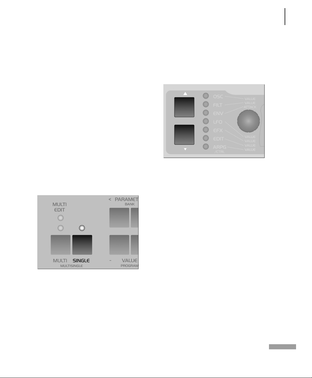
ACCESS VIRUS RACK 61
Parameter Selection and Data Entry
This knob is not labeled on the panel
with a parameter name that indicates its
purpose. Instead, the name of the
parameter and its function is shown in
the display . Apart from the envelope section, each of the parameter groups features these peripheral parameters that
are grouped in menus. These are ancillary parameters that complement the
directly accessible parameters. They may
be selected via the PARAMETER buttons
and controlled via the aforementioned
VALUE knob or the two VALUE buttons.
In order to return to the current Play
mode (MULTI, SINGLE or MULTI-SINGLE),
press the MULTI or SINGLE button. Then
you can switch programs as usual via the
VALUE buttons; the VALUE knob is now
disabled.
In Play mode, the other four knobs have
the same function as in the EDIT parameter group. Accordingly, you can access
Filter Cutoff, the two Definable knobs
and Master Volume directly.
If you want to return to the previously
selected parameter group or to the previously edited parameter, simply press
the UP or DOWN button.
When you call up a parameter in the display menus, you will also determining
the function of the dedicated knobs
(those with the fixed labels). If, for
example, you select the LFO section,
then the menu of one of the three LFOs
is indicated in the upper line of the display . The parameter that is controlled via
the VALUE knob or buttons is indicated
in the lower line. When you select the
LFO menu, you must also determine
which LFO is to be controlled by the dedicated knobs. So if you want to use these
labeled knobs to control the functions
LFO Rate, Shape, Contour and Keyfollow
for LFO 2, you must use the PARAMETER
buttons in the display to dial in one of
the parameters of LFO 2. This selected
parameter may then be edited via the
VALUE knob. At the same time, you can
control LFO 2's Rate, Shape, Contour and
Keyfollow via the four remaining knobs.
Page 64

62 CHAPTER 6
Operation
Once you've selected a parameter group
or section, the individual LEDs located
next to the knobs indicate whether or
not the knobs are assigned a function in
the currently active menu.
This means that if, for example, you edit
LFO 3 in the LFO section, then the
parameters Rate, Shape and Keyfollow
are directly accessible as is the case with
LFO 2. However, LFO 3 does not feature
the Contour parameter. Consequently,
the LED of the Contour knob will not
light up since the knob serves no function in this situation.
parameter groups in the direction of the
button that you are holding down. This
handy feature lets you swiftly go from
one parameter type to another, for
instance, from all chorus-related to all
delay-related parameters. If you also
hold the second parameter button
down, the menus will automatically
scroll in the selected direction. Once
you’ve scrolled to the desired parameter
group, simply select the desired parameter by pressing the button briefly. You
can also step through the parameters by
repeatedly pressing the same menu button.
If you press the PARAMETER buttons
briefly, you can scroll through the
parameters contained in the selected display menu step by step in the desired
direction. If you press and hold one of
the parameter buttons for a bit longer,
the display will automatically scroll
through the list of parameters in the
given menu. When you press and hold
one PARAMETER button and then press
the other PARAMETER button, the display will scroll through the menu in
The menus, particularly the EFFECTS
menu, contain parameter groups that
are related by virtue of their function,
for instance, all parameters that are used
to control the chorus. When you switch
the chorus off (CHORUS Dry/Eff = OFF),
all chorus parameters are of course irrelevant and will no longer appear in the
menu. In other words, when the chorus
is disabled, you can’t view its parameters. The reason for this is to make
menus clearer and less cluttered.
Page 65

ACCESS VIRUS RACK 63
Parameter Selection and Data Entry
The VALUE +/- buttons let you change
the value of the selected parameter in
steps. When you hold one of these buttons down, the value changes automatically and the longer you hold the button,
the faster the pace of the value change.
You can increase this pace even further
by pressing and holding one VALUE button and simultaneously pressing the
other VALUE button. If you press and
release both VALUE buttons simultaneously, the parameter is set to its
default value (mostly zero). This pertains
to unipolar parameters (value range of 0
to 127) as well as bipolar parameters
(value range of -64 to +63).
Located next to some of these parameters, you’ll see the abbreviations ”ENA”
and ”DIS”. The option ENA means
enable and DIS means disable.
well as the current value are displayed
for parameters that feature a dedicated
knob.
The Virus Rack features numerous
parameters. Many of these you can occasionally do without because they are not
absolutely essential to basic sound programming, and they do tend to make
the device a little more challenging to
handle. EXPERT mode can solve this
problem. It lets hide and show rarely
used parameters in the display menus.
You'll find the display for EXPERT mode
in the ARP/CTRL menu; it is the last
parameter in the list. In the chapter "The
Parameters", those parameters that
belong to EXPERT mode are labeled [XP].
The MULTI mode parameters feature a
dedicated menu called the Multi Edit
menu. Access it by pressing the Multi
button while the device is in MULTI
mode. The LED located over the MULTI
button will light up to indicate that the
Multi Edit menu is active. Press the
MULTI button again to return to normal
Play mode. If the device is in MULTI-SINGLE mode, press the MULTI and SINGLE
buttons simultaneously to access the
Multi Edit menu. It suffices to press
either the MULTI or SINGLE button to
return to normal Play mode from MULTISINGLE mode.
The triangular icon located next to the
parameter value indicates in which direction you have to change a value if you
would like to reset the parameter to the
value that has been stored to date. The
previously stored parameter value as
Page 66

64 CHAPTER 6
Operation
DISPLAY OF VALUES
When a menu is active, different display
options are available for parameters
with a dedicated knob. These can be
selected under the menu item KNOB DISPLAY in the CTRL menu:
OFF Knob movements are not dis-
played; the current contents of the display remain intact when you turn a
knob.
ON The lower row of the display is
being overwritten by the parameter's
value.
SHORT When you turn a knob, the cur-
rent contents of the lower display line
are briefly overwritten by data representing the change in parameter value;
once the action is completed, the original contents reappear in the lower display line.
LONG Same as SHORT, except that -
you guessed it - the display shows the
knob data for a longer period of time.
ON The contents of the display are
overwritten when you turn a knob; the
original menu does not reappear in the
display.
01111111111111111112
1 SYSTEM
KnobDispl Short≤
61111111111111111154
Page 67

All About The Memory
Page 68

66 CHAPTER 7
All About The Memory
STORE
The mode structure of SINGLE, MULTI
and MULTI SINGLE MODE is mirrored in
the STORE functions: In SINGLE MODE,
STORE saves the current SINGLE PROGRAM; in MULTI MODE, STORE saves the
current MULTI PROGRAM; and in MULTI
SINGLE MODE, the SINGLE PROGRAM of
the current PART is stored.
The STORE process is always the same
regardless of the operating mode: Press
STORE. You then gain access to the
STORE menu. There you can use the
PARAMETER buttons to move among the
individual letters in the lower name
entry line and the number of the destined memory location as well as the
bank number in the upper line. Use the
VALUE button to make entries. The term
in the upper display line indicates the
name of the memory location which you
will overwrite when you store the program.
. To belabor the point, when you store
a MULTI program, only the content of
the MULTI edit buffer is saved, not however the sound programs in the PARTs.
These must be stored individually in
MULTI SINGLE mode.
Once all of the entries correspond to the
data you have in mind, press STORE
again to conclude the process and return
to the previously active operating mode
of the Virus. If for whatever reason you
change your mind and want to cancel
the operation, simply press SINGLE or
MULTI to return to the previous operating mode without storing the program.
If you want to store the SINGLE programs in the PARTs to their original slots
in the SINGLE banks all at the same time,
simply press STORE and 1 C126 - Init
01111111111111111112
1 C126 - Init
[STORE] TO...
61111111111111111154
Page 69

COMPARE
When you press STORE and then UP or
DOWN, you will activate Compare mode.
After you have programmed or edited a
SINGLE sound, Compare mode lets you
hear the unedited sound that was originally stored in this memory slot. Press UP
or DOWN repeatedly to switch back and
forth between the Compare sound and
the edited sound so that you can - surprise, surprise – compare the two sounds.
Use the PARAMETER/BANK buttons and
the VALUE buttons to step through the
bank and program numbers of the Compare sound. This lets you search for a
new memory slot for the edited sound
and, at the same time, hear the sound
that you will overwrite. The edited
sound is not modified or overwritten
during this process. Press STORE to do
just that to the edited sound – store it.
Press MULTI or SINGLE to quit the STORE
process and/or exit Compare mode.
ACCESS VIRUS RACK 67
Compare
01111111111111111112
1 C126 -Init compare
61111111111111111154
Page 70

68 CHAPTER 7
All About The Memory
Page 71

Modmatrix And Definables
Page 72

70 CHAPTER 8
Modmatrix And Definables
CREATING MODULATIONS VIA ASSIGN
As a rule, it is of course desirable to be
able to create modulation routing configurations on a synthesizer. In other
words, you want to enjoy the freedom to
combine different modulation sources
and destinations as you see fit. Sometimes you may come up with ideas for
standard modulations that the ”hardwired” factory modulation routing
options simply can’t satisfy. This is why
we opted to equip the Virus with a versatile Modulation Matrix – you’re sure to
find it a welcome addition. On the Virus,
you can create modulation routing configurations freely as you see fit using
ASSIGN options. They are located in the
EDIT menu, where they appear under
the name of – you guessed it – ASSIGN).
The three ASSIGN options let you control
up to six modulation destinations via up
to three modulation sources. Simply go
to ASSIGN, select one of the modulation
sources (SOURCE) and one or several
modulation destinations (DESTINATION). Each of these configurations features a parameter that determines
modulation intensity (AMOUNT). ASSIGN
1 can control one modulation destination, ASSIGN 2 can control two and
ASSIGN 3 can control three modulation
destinations, each with independent
AMOUNTs.
the keyboard’s modulation wheel, to the
desired parameter. Y ou can also chose to
use the sound generator’s internal modulators, such as LFOs and envelopes, as
modulation sources. The control range
of the source may be limited via the
AMOUNT values or inverted so that the
modulation occurs strictly within the
desired value range for the target
parameter. For your target parameters,
you can chose from among virtually all
sound parameters that feature an infinitely variable control range – ergo, you
have more than 100 modulation destinations at your disposal! Since the sources
and destinations may be selected independently , you may even modulate a single parameter by using up to three
modulation sources simultaneously. For
this purpose, the control signals of the
modulation sources are added up or
overlapped. Conversely, you can also
modulate up to six parameters with just
one controller, which gives you all kinds
of sophisticated sound morphing
options. For this purpose, select the same
source for all three ASSIGN options so
that it modulates all six possible destina-
These ASSIGN options serve several purposes: for one, they let you assign an
external MIDI controller, for example,
Page 73

tions. This lets you radically reshape
sounds and even transform or morph
them into entirely different sounds.
01111111111111111112
1 ASSIGN
Source OFF≤
61111111111111111154
. You’ll find a list of available sources
and DESTINATIONS in the appendix.
[“Appendix” on page 203]
ACCESS VIRUS RACK 71
Creating Modulations via Assign
Page 74
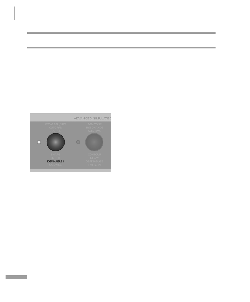
72 CHAPTER 8
Modmatrix And Definables
THE DEFINABLE KNOBS
The Virus is equipped with two knobs
that, rather than being dedicated to predefined tasks, may be assigned to different parameters by you, the user. This
option is quite handy, for it lets you control directly the many menu parameters
that do not feature a dedicated knob.
These DEFINABLE knobs operate in three
different modes:
GLOBAL The knob controls the param-
eter that you have set to Global in the
DEFINABLE menu regardless of what the
other settings and the selected SINGLE
program may be.
this program. If, however, you have not
selected a parameter for this program
(DEFINABLE Single = OFF), the setting for
DEFINABLE Global is automatically
enabled.
MIDICONTRL Here the controller num-
ber entered in the DEFINABLE MIDI
menu is sent regardless of what the
other settings and the selected SINGLE
program may be. Comparable to a small
MIDI fader box, this mode is used to control connected MIDI devices. Note that
this information is not processed internally in the Virus.
The setting for the actual DEFINABLE
mode is global. Under normal circumstances, you should set DEFINABLE mode
to ”Single” because this is the most versatile mode. When you select a SINGLE
sound whose DEFINABLE mode is set to
”Single”, this setting is of course
enabled. If not, Global DEFINABLE mode
is enabled.
01111111111111111112
1 DEFINABLE 1
Mode Single≤
61111111111111111154
INGLE The knob controls the parame-
ter that you have set to Single in the
DEFINABLE menu. The setting for this
parameter is stored in the SINGLE program and called up whenever you select
Page 75

Master Clock And Midi-Clock
Page 76

74 CHAPTER 9
Master Clock And Midi-Clock
MASTER CLOCK AND MIDI-CLOCK
The Virus is equipped with a global clock
generator that lets you sync the LFOs,
arpeggiators and delay up to a common
song tempo and rhythm. The clock generator works either internally with a
freely variable speed or it can, in turn, by
synced up to the MIDI clock of an external sequencer. This synchronization
occurs automatically when the device
receives a MIDI clock signal via its MIDI
In. You can vary the speed of the clock
generator within a range of 63 to 190
BPM (beats per minute) via CLOCK
TEMPO. When the device is synchronized
via MIDI clock, the clock generator automatically accepts the speed dictated by
the connected sequencer; the internal
tempo setting is in this case meaningless
and thus disabled. The individual sections of the Virus are synced up to the
clock generator at rhythmic intervals
such as 1/16, 1/4 and so forth. These values may be assigned individually for
every section. (ARPEGGIATOR CLOCK,
CLOCK LFO 1, CLOCK LFO 2, CLOCK LFO
3, DELAY CLOCK, see the respective sections).
In SINGLE MODE, CLOCK TEMPO pertains
to the current SINGLE PROGRAM and is
stored along with it. In MULTI MODE, the
CLOCK TEMPO settings for the involved
SINGLE PROGRAMs are ignored. Instead,
all involved SINGLE PROGRAMs are controlled via the same clock generator. Its
CLOCK TEMPO is saved in the MULTI
PROGRAM (as are the settings for the
global delay effect).
This feature lets you control the LFOs
and arpeggiators of several MULTI P ARTS
in a common rhythmic context.
. A small symbol will appear in the dis-
play
. When the Virus is receiving MIDI
Clock data. If you’re sure you do NOT
want the device to be synchronized
automatically to MIDI clock, set MIDI
CLOCK RX to Off (in the CTRL menu).) To
avoid confusion, please keep in mind
that MIDI Clock is not the same thing as
MIDI Time Code. The latter doesn’t deal
with tempo at all but with time-related
information structured in hours, minutes, seconds, etc. which is of no benefit
to you in this context.
Page 77

The Effects Section
Page 78

76 CHAPTER 10
The Effects Section
THE EFFECT SECTION
For every SINGLE program and every
PART, you can access two stereo effects
individually. You’ll find these effects –
analog boost and chorus – in the aptly
named EFFECTS menu.
The vocoder and the delay/reverb section are each available just once, but you
can address them individually via the
PARTs’ Effect Send parameter. In the signal path, all effects are connected in
series in accordance with their sequence
in the Effects menu.
Each SINGLE program contains its own
settings for the delay/reverb section. In
MULTI mode, the sound programs
involved share the same delay/reverb
section. For this reason, the parameter
values are determined by the settings of
the currently active MULTI program (also
see [“EFX Section” on page 115]).
Page 79

Audio Inputs
Page 80

78 CHAPTER 11
Audio Inputs
AUDIO INPUTS
You can also opt to use external audio
signals in place of the on-board oscillators for the sound programs or MULTI
PARTs. The Virus is equipped with two
inputs for external signals. Y ou can route
these to its sound generating components (the filters, the saturation stage as
well as the volume and panorama stage)
or patch them directly to the effects section of the Virus. External audio signals
may also be used as carrier or modulator
signals for the vocoder. Any PART that
you use to process an external audio signal in MULTI mode can, like every other
PART, be routed freely to one or two of
the four audio outputs.
The Virus Rack is equipped with two
audio inputs on the back panel. Additionally the left input is accessible on the
front panel. When you plug a cord into
the front input, the rear left input is disabled.
As a rule, when you’re processing external audio signals, you need to distinguish between the following two
operating modes:
to 100%, the resonant frequencies of the
filters and oscillators can be played in a
tempered manner via the INPUT signal.
This lets you play entire chords as well as
arpeggiator lines using the filters. The
noise generator is also active in INPUT
mode.
STATIC In Input Static mode, the exter-
nal audio signals are audible via the output without having to trigger a note.
Bear in mind that the oscillators as well
as all functions that have to do with trigger and pitch are disabled (envelopes,
LFO Env mode, Keyfollow...) In INPUT
Static mode. When you set the device to
this mode, one voice of the Virus is activated automatically. If you select a stereo source (L+R) for INPUT Select, two
voices are activated much like in UNISON
mode: T win. In this case, you can also use
the UNISON Pan Spread parameter to
determine the basic width of the panorama and UNISON LFO Phase to shift
the LFO phase position between the
voices.
DYNAMIC To make external signals
audible in this operating mode, the volume envelope must be triggered via a
note. This option, for example, lets you
create typical gater effects. INPUT
Dynamic mode is also polyphonic. If you
set the KEYFOLLOW value for the filters
Page 81

TOEFFECTS An alternative to INPUT
Static mode, here the audio signal is
routed directly to the effects section of
the SINGLE program or PART. This mode
doesn’t use the voices of the Virus, which
means that its polyphonic performance
remains fully intact and available. The
filter section is unavailable in this mode.
01111111111111111112
1 INPUT
Mode Dynamic≤
61111111111111111154
ACCESS VIRUS RACK 79
Audio Inputs
OSC Volume / Input
When one of the two INPUT modes is
activated, the OSC VOL parameter rather
than the oscillators controls the level of
the INPUT signal in front of the Filter section and of course also the gain of the
SATURATION stage. In INPUT Dynamic
mode, the level increases quite rapidly
when you play several voices polyphonically. The reason for this is that – in contrast to when you’re dealing with several
oscillator signals – the voices are correlated because they are receiving an identical input signal. In the event that the
Virus generates distortion when you’re
dealing with this type of signal routing
set-up, be sure to back off the input level
a tad via the OSC VOL knob.
Page 82

80 CHAPTER 11
Audio Inputs
Input global Settings
Input Level Indicator
In the Input menu, you'll find a gain
switch (INPUT Gain) that increases the
input signal by 20 decibels before it is
sent to the digital analog converter. This
means that with the proper cords you
can connect a microphone, an electric
guitar or a record player directly to the
Virus Rack. However, to attain the best
possible sound quality, it is advisable to
patch the signal into an appropriate signal processor such as a microphone
preamplifier , a mixer, or a guitar preamp
before you route it into the input of the
Virus. Please turn down the Master Volume knob before you turn input gain up.
Be aware that boosting the signal by 20
decibels increases the level tenfold!
Additionally the Virus is equipped with
an amplifier stage (INPUT Boost), that
can boost the signal level of the two
inputs continuously by up to 36 dB. The
signal is boosted in the digital section of
the Virus, so the noise level of the analog-digital converters increases automatically. Consequently you should dial in
the cleanest, loudest possible signals at
the external sound generator, or use the
INPUT Gain switch.
Alternatively, the RATE LEDs of LFO 1
and 2 can also serve as level indicators
for the left and right external audio
inputs. The Virus automatically switches
to this level indicator mode when the
selected SINGLE program accesses the
external audio inputs. The LEDs will flash
rapidly to indicate that the inputs are
being overloaded. You should dial in the
proper level on the device that is sending the analog signals. The reason for
that you want to feed the highest possible clean signal level to the analog-todigital converters of the Virus so that
they will deliver the best possible performance ( Siehe “LED Mode” auf
Seite 155).
Since record players have a characteristic
frequency response, we equipped the
Virus Rack with a suitable Phono equalizer. It may be activated via the "INPUT
Phono" parameter.
Page 83

Audio Routing
Page 84

82 CHAPTER 12
Audio Routing
THE AUDIO OUTPUTS
In MULTI mode, you can choose a mono
or stereo audio output in the OUTPUT
Select menu independently for every
PART.
In contrast to the majority of other
effects, the delay/reverb section is not
available individually for each PART.
Instead, it processes the signals of the
PARTs collectively. You can, however,
control the intensity of the effect individually for each PART using the respective Effect Send parameter.
Consequently, the delay/reverb section
has just one signal output, which cannot
be distributed to the outputs of the individual PARTs.
This is why , for example, the delay ef fect
of a PART that is routed to the pair of
outputs labeled OUT 2 will still be audible on OUT 1. This can be desirable yet
may also lead to confusion. To encourage the former and prevent the latter,
set the Effect Send parameter of the
PART to zero when you’re using individual outputs.
In MULTI mode, the delay/reverb section
feature its own OUTPUT Select that is
independent of the PARTs.
Page 85

Categories
Page 86

84 CHAPTER 13
Categories
SOUND CATEGORIES
The Virus gives you the option of classing
the stored SINGLE sounds in categories.
With the benefit of these categories,
you’ll be able to find a desired sound
much faster.
You have the following categories at
your disposal:
Off, Lead, Bass, Pad, Decay, Plug, Acid,
Classic, Arpeggiator, Effects, Drums, Percussion, Input, Vocoder, Favourite 1,
Favourite 2, Favourite 3
Every SINGLE sound can be assigned to
up to two categories by means of the
parameters CATEGORY 1 and CATEGORY
2. For example, you could assign the
attributes "Bass" and "Acid" or "Lead"
and "Favorite 1" to a given sound. These
categories may be changed at any time
and can be stored along with the sound.
The factory sounds are assigned default
categories.
Once you’ve assigned categories, you can
search for the sounds within a specific
category in SINGLE mode and MUL TI-SINGLE mode:
matter if this sound has been assigned to
the category via CATEGORY 1 or CATEGORY 2; in either case, it will show up in
the list. While you’re selecting sounds,
SINGLEs that don’t belong to the currently selected category are simply
skipped over when you hold the SINGLE
button down.
Press and hold the SINGLE button, then
use the PARAMETER buttons to select
the category in which you want to search
for sounds. Hold the SINGLE button
down and use the VALUE buttons to
select sounds that are assigned to the
currently selected category. It doesn’t
Page 87

Random Patch Generator
Page 88

86 CHAPTER 14
Random Patch Generator
RANDOM PATCHES
The RANDOM PA TCH GENERA TOR can be
used to generate a new sound automatically or a modify an existing sound at
random. The PAR DEPTH and AMOUNT
parameters let you determine how radically the sound is changed. Depending
on the values that you set here, the RANDOM PATCH GENERATOR will do
anything from modifying sound parameters subtly to morphing one sound into
an entirely different sound.
The RANDOM PATCH GENERATOR is activated when you presses the button
STORE while the display is showing one
of the two RANDOM parameters. The
results of the computation are stored in
the Edit buffer and can be heard immediately. You can also press STORE several
times in order to create successive sound
changes. If you want store a sound permanently that the RANDOM PATCH
GENERATOR has created, simply save it
to a SINGLE memory slot in the usual
manner. For this purpose, press the SINGLE button to activate PLAY mode (SINGLE mode or MULTI-SINGLE mode) so
that the STORE button’s original
function is restored.
If you want to restart the process with
the original sound settings, simply return
to PLAY mode back and select the desired sound again.
PAR DEPTH This parameter determines the number of sound parameters that are influenced by the RANDOM PATCH GENERA TOR. If you enter a low value for PAR DEPTH, just a few parameters will be modified. Beyond that, the manner in which the few parameters are edited assures that the sound is manipulated “organically”. This simply means that it isn’t bent radically so that, for example, the given sound can still be played “tonally”.
As you increase the values for PAR
DEPTH, other parameters that have a
greater impact on the timbre of the
sound are changed. At higher values, the
RANDOM PATCH GENERATOR tends to
generate noise-like sounds or special
effects.
01111111111111111112
1 RANDOM [STORE]
ParaDepth 0≤
61111111111111111154
AMOUNT This parameter determines the intensity of the RANDOM PATCH GENERATOR’s effect on the sound parameters. At lower values, sound changes are fairly subtle, but you can intensify the effect
Page 89

by repeatedly pressing the STORE button. Higher values introduce fundamental changes to the sound.
01111111111111111112
1 RANDOM [STORE]
Amount 0≤
61111111111111111154
. Be aware that RANDOM PAR DEPTH
and RANDOM AMOUNT are not actual
sound parameters. They merely set the
parameters for the RANDOM PATCH
GENERATOR and only take effect when
the RANDOM PATCH GENERATOR is activated. Not until then will the sound be
changed.
ACCESS VIRUS RACK 87
Random Patches
Page 90

88 CHAPTER 14
Random Patch Generator
Page 91

Additional Functions
Page 92
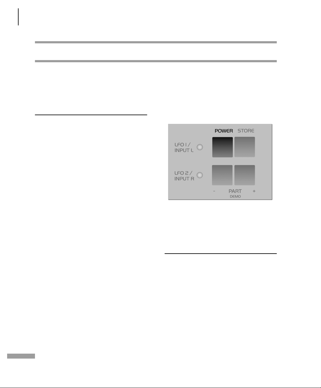
90 CHAPTER 15
Additional Functions
ADDITIONAL FUNCTIONS
The Virus features a Panic function to
remedy stuck notes caused by MIDI
transmission parity errors and the like.
When you press the POWER and the
STORE button simultaneously, then all
voices of the Virus that are still sounding
will be released.
Panic Function
A double-click on both buttons initiates
a controller reset. The various voices that
are still sounding will be cut off instantly
and controllers such as the modulation
wheel, channel volume and pitch bender
are reset to the default settings.
Audition function
On the Virus panel, you can trigger notes
without using a keyboard. When you
press the UP and DOWN buttons simultaneously , the Virus will play the note C3. If
you hold the buttons down for longer
than a second, the note will continue to
sound after you release the buttons.
Page 93
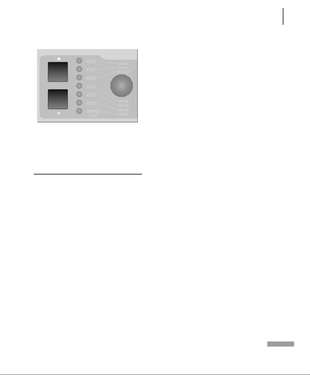
ACCESS VIRUS RACK 91
Additional Functions
Reset Function
If you get the impression that the VIRUS
is behaving unstable or indeed strange,
we suggest you perform a system reset.
Holding the PARAMETER LEFT button
while switching the VIRUS on, performs
a system reset. No data will be lost during this procedure, although some global system settings as ”Global Channel”
will be reset.
Page 94

92 CHAPTER 15
Additional Functions
Page 95

The Parameters
Page 96
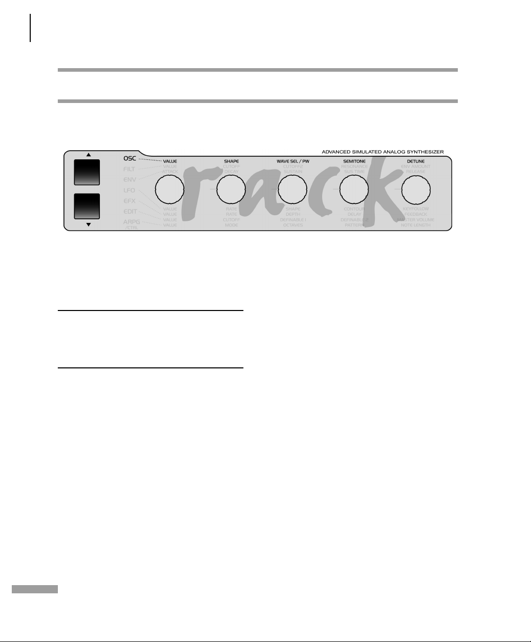
94 CHAPTER 16
The Parameters
OSC SECTION (ENCODER)
The following section lists all parameters
in the Virus, each with a brief definition
or explanation.
. In case, a parameter is only available
in the Expert Mode, the prefix [XP] has
been used in front of the parameter’s
name.
The function of the Encoders depends on
the selected section and the currently
active display menu. If the given Encoder
does not have an assignment, the corresponding LED on the front panel will
extinguish. If no menu is activate (none
of the seven section LEDs is illuminated),
then the Encoder assignments are determined by the Edit section.
EXPERT MODE: The Virus Rack features
numerous parameters. Many of these
you can occasionally do without because
they are not absolutely essential to basic
sound programming, and they do tend
to make the device a little more challenging to handle. EXPERT mode can
solve this problem. It lets hide and show
rarely used parameters in the display
menus. In the chapter "The Parameters",
those parameters that belong to EXPERT
mode are labeled (XP). When EXPERT
Mode is switched to "Off", then those
parameters are hidden.
Page 97

Oscillator 1
SHAPE This control feature lets you
determine the waveshape for the WAVE
section (one of 64 variable spectral
waveshapes). The waveshape is infinitely
variable from sawtooth through to pulse
waves. Wave or pulse width selection is
executed via the SHAPE and WAVE SEL/
PW control features (see appropriate
section): If SHAPE has a value less than
the value of the center position, then
WAVE SEL/PW determines the waveshape; if the SHAPE value is higher than
that of the center position, then WAVE
SEL/PW determines the pulse width.
ACCESS VIRUS RACK 95
OSC Section (Encoder)
SEMITONE Determines the interval between the second oscillator and the first oscillator: Control range +/-48 semitones, assigned in semitone steps.
Oscillator 2
SHAPE Same as OSCILLATOR 1; see para-
graph above.
W AVE SEL/PW has two functions, depending on the SHAPE (see appropriate section) value:
When SHAPE has a value lower than
that of the center position, then WAVE
SEL/PW lets you select from the 64 spectral waveshapes available in the ROM of
the Virus. Waveshape 1 is a sine wave;
No. 2 a triangle, the remainder of the
waves feature different combinations of
frequencies.
When the SHAPE value is higher than
that of the center position, then WAVE
SEL/PW determines the pulse width: At
the far left position the pulse width is
50%, at the far right it is 0%, which
means the wave no longer oscillates.
WAVE SEL/PW Same as OSCILLATOR 1; see paragraph above.
SEMITONE Same as OSCILLATOR 1; see paragraph above.
DETUNE Detunes the second oscillator relatively to the first. With this parameter , you can dial in everything from slight deviations in pitch to major fluctuations between the two oscillators.
Page 98

96 CHAPTER 16
The Parameters
OSC SEKTION (MENU)
Oscillator 1
upwards by one octave for every two
ascending octaves you play (quarter note
scale); at 0 the keyboard control option
is off. Negative values generate opposite control intensities.
WAVE Selects among of 64 spectral waveshapes. This parameter is identical
to WAVE SEL/PW (see appropriate section) when SHAPE (see appropriate section) is set to the left half of its control
range. However, in contrast to WAVE
SEL/PW, WAVE is always available
regardless of the current SHAPE setting.
01111111111111111112
1 OSCILLATOR1
Wave Sin≤
61111111111111111154
[XP] KEY FOLLOW Determines the intensity of the pitch control via the keyboard: At the value +32 (standard setting) the oscillator is controlled normally, i.e. the octave you are playing is identical to the oscillator octave; at +63 every ascending octave you play transposes the oscillator upwards by two octaves (whole note scale); +15 transposes the oscillator
01111111111111111112
1 OSCILLATOR1
Keyfollow +32≤
61111111111111111154
Page 99

Oscillator 2
WAVE Same as OSCILLATOR 1; see para-
graph above.
[XP] KEYFOLLOW Same as OSCILLATOR 1; see paragraph above.
SYNC Synchronizes the second oscillator with the first: The SYNC function forces Oscillator 2 to interrupt its wave cycle and restart it at the same time as Oscillator 1 starts its cycle. The effect of this measure is that pitch deviations and intervals are no longer audible as such; what you hear are tonal modifications: Repeated interruption of the Oscillator 2 wave cycle generates new tonal spectra with a great deal of overtone content. The tone of a given spectrum can be influenced via the SEMITONE knob, among other control features.
01111111111111111112
1 OSCILLATOR2
Sync ON≤
61111111111111111154
ACCESS VIRUS RACK 97
OSC Sektion (Menu)
[XP] FM AMOUNT Controls the frequency modulation intensity of the second oscillator by the first. Depending on the selected FM AMOUNT and the interval between the oscillators, the frequency modulation generates everything from slightly to radically enriched spectra. In the Virus you have the option of combining the two functions called oscillator synchronization (SYNC) and frequency modulation (FM AMOUNT) to generate new harmonic spectra. The characteristics of the frequency modulation can be modified with the FM Mode parameter (in the OSCILLATOR EDIT menu). You may also select an external audio signal and have Oscillator 2 modulate its frequency.
01111111111111111112
1 OSCILLATOR2
FmAmt 22≤
61111111111111111154
FILT ENV -> PITCH This parameter determines the intensity at which the filter envelope controls the pitch of the second oscillator (PITCH OSC 2).
01111111111111111112
1 OSCILLATOR2
FltEnv~Ptch +0≤
61111111111111111154
Page 100

98 CHAPTER 16
The Parameters
FILT ENV -> FM It determines the intensity at which the filter envelope controls the frequency modulation (FM AMOUNT). This as well as the previous parameter are ”relics” from the predecessor model of the Virus. Modulations such as these may also be implemented via the Modulation Matrix (see the section ”ASSIGN” below).
01111111111111111112
1 OSCILLATOR2
FltEnv~Fm +0≤
61111111111111111154
Oscillators
OSC BAL Determines the balance
between the Oscillators 1 and 2 volume
level.
01111111111111111112
1 OSCILLATORS
Balance 64≤
61111111111111111154
VOLUME This knob has two functions:
In the left half of its control range up
to the center position (MIDI value 64),
OSC VOL determines the master volume
of the three oscillators prior to the filter
section input. The Noise Generator and
the Ringmodulator are not affected by
the master volume knob OSC VOL. Their
level is controlled separately in the
OSCILLATOR EDIT menu (see appropriate
section).
In the right half of the control range
from the center position to the far right,
OSC VOL increases the saturation intensity (Gain) for the input of the SATURA-
TION stage (see appropriate section);
however this adjustment is compensated
post-SATURATION stage so that when
you adjust the gain you are not actually
increasing the volume, only manipulat-
 Loading...