

Page 1
TVAC26000
D Bedienungsanleitung
User manual
F Manuel utilisateur
Gebruikershandleiding
Brugerhåndbog
Version 11/2011
Page 2

English
Français
Dansk
Nederlands
Deutsch
Diese Bedienungsanleitung enthält wichtige Hinweise zur Inbetriebnahme und Handhabung.
Achten Sie hierauf, auch wenn Sie dieses Produkt an Dritte weitergeben.
Heben Sie deshalb diese Bedienungsanleitung zum Nachlesen auf!
Eine Auflistung der Inhalte finden Sie im Inhaltsverzeichnis mit Angabe der entsprechenden Seitenzahlen auf
Seite 7.
These user manual contains important information for installation and o p eration.
This should be also noted when this product is passed on to a third party.
Therefore look after these operating instructions for future reference!
A list of contents with the corresponding page number can be found in the index on page 18.
Ce mode d’emploi appartient à de produit. Il contient des recommandations en ce qui concerne sa
mise en service et sa manutention. Veuillez en tenir compte et ceci également lorsque vous remettez
le produit à des tiers. Conservez ce mode d’emploi afin de pouvoir vous documenter en temps utile!
Vous trouverez le récapitulatif des indications du contenu á la table des matières avec mention de la page
correspondante á la p age 29.
Deze gebruiksaanwijzing hoort bij dit p roduct. Er staan belagrijke aanwijzingen in betreffende de
ingebruikname en gebruik, ook als u dit product doorgeeft aan derden.
Bewaar deze hendleiding zorgvuldig, zodat u deze later nog eens kunt nalezen!
U vindt een opsomming van de inhoud in de inhoudsopgave met aanduiding van de paginanummers op
pagina 40.
Denne manual hører sammen med dette produkt. Den indeholder vigtig information som skal bruges
under opsætning og efterfølgende ved service. Dette skal huskes også når produk ter gives videre til
anden part. Læs derfor denne manual grundigt igennem også for fremtiden.
Indholdet kan ses med sideanvisninger kan findes i indekset på side 51.
2
Page 3
TVAC26000
Version 11/2011
Originalbedienungsanleitung in deutscher Sprache. Für künftige Verwendung aufbewahren!
Bedienungsanleitung
3
Page 4

Einführung
Sehr geehrte Kundin, sehr geehrter Kund e,
wir bedanken uns für den Kauf dieses Produkts.
Dieses Produkt erfüllt die Anforderungen der geltenden europäischen und nationalen Richtlinien. Die
Konformität wurde nachgewiesen, die entsprechenden Erklärungen und Unter lagen sind beim
Hersteller (www.abus-sc.com) hinterlegt.
Um diesen Zustand zu erhalten und einen gefahrenlosen Betrieb sicherzustellen, müssen Sie als Anwender
diese Bedienungsanleitung beachten!
Lesen Sie sich vor Inbetriebnahme des Produkts die komplette Bedienungsanleitung durch, beachten Sie alle
Bedienungs- und Sicherhe i ts hin weis e!
Alle enthaltenen Firmennamen und Produktbezeichnungen sind Warenzeichen der jeweiligen Inhaber.
Alle Rechte vorbehalten.
Bei Fragen wenden Sie sich an ihren Facherrichter oder Fachhandelspartner!
Haftungsausschluss
Diese Bedienungsanleitung wurde mit größter Sorgfalt erstellt. Sollten Ihnen dennoch Auslassungen oder
Ungenauigkeiten auffallen, so teilen Sie uns diese bitte auf der Rückseite des Handbuchs angegebener
Adresse mit.
Die ABUS Securit y-Center GmbH übernimmt keinerlei Haftung für technische und typographische Fehler
und behält sich das Recht vor, jederzeit ohne vorherige Ankündigung Änderungen am Produkt und an den
Bedienungsanleitun gen vor zun ehmen.
ABUS Security-Center ist nicht für direkte und indirekte Folgeschäden haftbar oder verantwortlich, die in
Verbindung mit der Ausstattung, der Leistung und dem Einsatz dieses Produkts entstehen. Es wird keinerlei
Garantie für den Inhalt dieses Dokuments übernommen.
4
Page 5
Das Symbol mit dem Blitz im Dreieck wird verwendet, wenn Gefahr für die
Gesundheit besteht, z.B. durch elektrischen Schlag.
Bei Sach- oder Personenschäden, die durch unsachgemäße Handhab u n g oder
Haftung. In solchen Fällen erlischt jeder Garantieanspruch!
Symbolerklärung
Ein im Dreieck befindliches Ausrufezeichen weist auf wichtige Hinweise in dieser
Bedienungsanleitung hin, die unbed ingt zu beachten sind.
Dieses Symbol ist zu finden, wenn Ihnen besondere Tipps und Hinweise zur Bedienung
gegeben werden sollen.
Wichtige Sicherheitshinweise
Bei Schäden die durch Nichtbeachten dieser Bedienungsanleitung verursacht werden,
erlischt der Garantieanspruch. Für Folgeschäden übernehmen wir keine Haftung!
Nichtbeachten der Sicherheitshinweise verursacht werden, übernehmen wir keine
Dieses Gerät wurde unter Einhaltu ng inter n at ion aler Sicherheitsstandards gefertigt.
Bitte lesen Sie die folgenden Sicherheitshinweise aufmerksam durch.
Sicherheitshinweise
1. Stromversorgung
100-240 VAC Wechselspannung, 50 – 60 Hz (über Steckernetzteil an 12 VDC)
Betreiben Sie dieses Gerät nur an einer Stromquelle, welche die auf dem Typenschild angegebene
Netzspannung liefert. Falls Sie nicht sicher sind, welche Stromversorgung bei Ihnen vorliegt, wenden Sie
sich an Ihr Energieversorgungsunternehmen. Trennen Sie das Gerät von der Netzstromversorgung,
bevor Sie Wartungs- oder Installationsarbeiten durchführen.
2. Überlastung
Vermeiden Sie die Überlastung von Net zstec kdosen, Verlängerungskabeln und Adaptern, da dies zu
einem Brand oder einem Stromschlag führen kann.
3. Flüssigkeiten
Schützen Sie das Gerät vor dem Eindringen von Flüssigkeiten aller Art.
4. Reinigung
Reinigen Sie das Gerät nur mit einem feuchten Tuch ohne scharfe Reinigungsmittel.
Das Gerät ist dabei vom Netz zu trennen.
5. Zubehör
Schließen Sie nur ausdrücklich dafür vorgesehene Geräte an. Andernfalls kann es zu
Gefahrensituationen oder Schäden am Gerät kommen.
5
Page 6
alle Geräte von Netz- und Niederspannungsstromkreis getrennt sind.
Nehmen Sie im Zweifelsfall die Montage, Installation und Verkabelung nicht selbst vor, sondern
werden können.
informieren Sie den Lieferdienst.
Warnungen
Vor der ersten Inbetriebnahme sind alle Sicherheits- und Bedienhinweisung zu beachten!
1. Beachten Sie die folgende Hinweise, um Schäden an Netzkabel und Netzstecker zu vermeiden:
• Verändern oder manipulier en Sie Net zkabel und Netzstecker nicht.
• Wenn Sie das Gerät vom Netz trennen, ziehen Sie nicht am Netzkabel, sondern fassen Sie den
Stecker an.
• Achten Sie darauf, dass das Netzkabel so weit wie möglich von Heizgeräten entfernt ist, um zu
verhindern, dass die Kunststoffummantelung schmilzt.
2. Befolgen Sie diese Anweisungen. Bei Nichtbeachtung kann es zu einem elektrischen Schlag kommen:
• Öffnen Sie niemals das Gehäuse oder das Netzteil.
• Stecken Sie keine metallischen oder feuergefährlichen Gegenstände in das Geräteinnere.
• Um Beschädigungen durch Überspannungen (z. B. Gewitter) zu vermeiden, verwenden Sie bitte
einen Überspannungsschutz.
3. Bitte trennen Sie defekte Geräte sofort vom Stromnetz und informieren Ihren Fachhändler.
Vergewissern Sie sich bei Instal lat ion in einer vorha nd enen Vide oüb erwachungsanlage, dass
überlassen Sie dies einem Fachmann. Unsachgemäße und laienhafte Arbeiten am Stromnetz
oder an den Hausinstallationen stellen nicht nur Gefahr für Sie selbst dar, sondern auch für
andere Personen.
Verkabeln Sie die Installationen so, dass Netz- und Niederspannungskreise stets getrennt
verlaufen und an keiner Stelle miteinander verbunden sind oder durch einen Defekt verbunden
Vermeiden Sie folgende widrige Umgebungsbedingungen bei Betrieb:
• Nässe oder zu hohe Luftfeuchtigkeit
• Extreme Kälte oder Hitze.
• Direkte Sonneneinstrahlung
• Staub oder brennbare Gase, Dämpfe oder Lösungsmittel
• starke Vibrationen
• starke Magnetfelder, wie in der Nähe von Maschinen oder Lautsprechern.
Auspacken
Während Sie das Gerät auspacken, handhaben sie dieses mit äußerster Sorgfalt.
Bei einer eventuellen Beschädigung der Originalverpackung, prüfen Sie zunächst das Gerät.
Falls das Gerät Beschädigungen aufweist, senden Sie dieses mit Verpackung zurück und
6
Page 7

Inhaltsverzeichnis
Bestimmungsgemäße Verwendung ..................................................................................................... 8
1.
2. Lieferumfang ........................................................................................................................................... 8
3. Merkmale und Funktionen ..................................................................................................................... 8
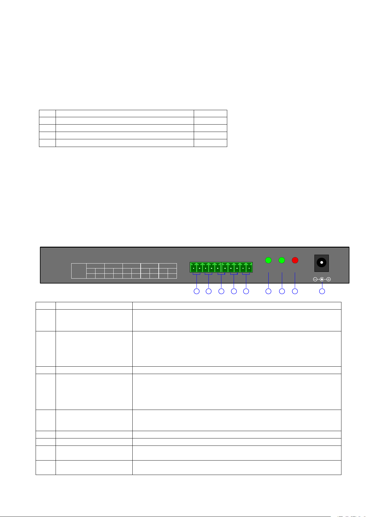
4. Gerätebeschreibung .............................................................................................................................. 8
4.1 Rückansicht des Bedienpults ......................................................................................................... 8
4.2 Vorderansicht des Bedienpu lts ...................................................................................................... 9
4.3 Joystick Steuerung ....................................................................................................................... 10
4.4 LCD Display ................................................................................................................................. 10
5. Bedienpult Konfiguration .................................................................................................................... 10
5.1 Bedienpult Menü .......................................................................................................................... 10
5.2 Protokoll und Baudrate änder n .................................................................................................... 11
6. Typischer Schaltplan ........................................................................................................................... 12
6.1 Steuerung Speed Dome ............................................................................................................... 12
6.2 Steuerung DVR ............................................................................................................................ 12
7. Wartung ................................................................................................................................................. 13
7.1 Wartung ........................................................................................................................................ 13
7.2 Reinigung ..................................................................................................................................... 13
8. Entsorgung ........................................................................................................................................... 13
9. Technische Daten ................................................................................................................................. 13
7
Page 8
Nr.
Posten
Anzahl
1
Bedienpult
1 2 12V DC Netzteil
1 3 5PIN Anschlussklemme
2 4 Bedienungsanleitung
1
10 1
PTZ DVR PW
DC-12V
1 2 3 4 5
RS485-EXPORT
6
7 8 9
RS485
EXPORT
PTZ-CON PTZ-AUX Ground DVR-AUX DVR-CON
10 9 8 7 6 5 4 3 2 1
Ta Tb Ra Rb G G Ra Rb Ta Tb
Nr.
Anschluss
Erklärung
PTZ-CON
ebenfalls den PTZ Speed Dome steuern.
3
Ground
Masseanschluss
einen DVR steuern.
DVR-CON
Verbinde Bedienpult PIN2 (Ta) mit DVR KB PIN D+, und verbind e
6
PTZ Kontrollleuchte
Im PTZ Betriebsmodus leuchtet und blinkt die LED grün.
7
DVR Kontrollleuchte
Im DVR Betriebsmodus leuchtet und blinkt die LED grün.
ist.
9
Spannungsversorgung
DC-12V
Anschluss der Spannungsversorgung
1. Bestimmungsgemäße Verwendung
Das Bedienpult TVAC26000 dient zur zentralen Steuerung von PTZ Kameras und DVRs mit RS-485Schnittstelle.
Folgende DVRs sind kompatibel: TVVR4xxxx, TVVR50xxx und TVVR60xxx.
2. Lieferumfang
3. Merkmale und Funktionen
• Steuerung von PTZ Speed Dome
• Steuerung von DVRs
• Bedienpult kann bis zu 31 DVRs verwalten
• Bedienpult kann bis zu 255 PTZ Geräte verwalten
4. Gerätebeschreibung
4.1 Rückansicht des Bedienpults
1 Ausgang für PTZ
Steuerung
2
Eingang für zusätzliches
Bedienpult zur PTZ
Steuerung
PTZ-AUX
4
Eingang für zusätzliches
Bedienpult zur DVR
Steuerung
DVR-AUX
RS485 Anschluss zur Verbindun g von Bedi enp ult un d PT Z Speed Dom e.
Ta ist für RS485+, und Tb ist für RS485-.
Verbindung zwischen Bedi enpu lt und zusä t zlich em Bedienpult zur PTZ
Steuerung herstellen. Bedienpult PIN8 (Ra) mit zusätzlichem Bedienpult
PIN10 (Ta) verbinden, und Bedienpult PIN7 (Rb) mit zusätzlichem
Bedienpult PIN9 (Tb) verbinden. Das zusätzliche Bedienpult kann nun
Verbindung zwischen Be di enpu lt und zusä t zlich em Bedienpult zur DVR
Steuerung herstellen. Bedienpult PIN4 (Ra) mit zusätzlichem Bedienpult
PIN2 (Ta) verbinden, und Bedienpult PIN3 (Rb) m it zus ätzlichem
Bedienpult PIN1 (Tb) verbinden. Das zusätzliche Bedienpult kann nun
5 Ausgang für DVR
Steuerung
8
Power LED PW
Bedienpult PIN1 (Tb) mit DVR KB PIN D-.
Die Power LED leuchtet rot, sobald die Spannungsversorgung hergestellt
8
Page 9

Taste
Erklärung
ESC
Zurück zum vorherigen Menü
Setup
Für drei Sekunden gedrückt halten, um in das Konfigurationsmenü zu gelangen
(Standard Passwort: 8888, Master Passwort: 1111)
Search
Drücken Sie eine Sekunde, um die PTZ Konfiguration zu sehen
Shift
Betriebsmodus zwischen DVR oder PTZ ändern
MENU
Ruft das Hauptmenü auf
DVR
F1
Reserve
F2
Reserve
REC
Sie gelangen in das Menü des angeschlossenen Rekorders
MON
Reserve
EDIT
Änderungen im Menü des Rekorders vornehmen
F3
Progammierung einer Tour
PLAY
Ruft die Wiedergabe im Rekorder auf
MAIN/AUX
Ausgabe zwischen zwei angeschlossenen Monitoren wählen (2 Sekunden drücken)
A
Wählen Sie zwischen Groß- und Kleinbuchstaben oder Zahlen
F4
Starten einer Tour
PTZ
Ruft das PTZ Menü auf.
AUX
Reserve
Shut Down
Rekorder herunterfahren
Addr
ID für PTZ Speed Dome oder DVR ändern
Clear
Aktuelle Eingabe löschen
ENTER
Aktuelle Eingabe bestätigen
0-9
A – Z
Zahlen: 0, 1, 2, 3, 4, 5, 6, 7, 8, 9
A-Z (26 Zeichen)
PRESET
Preset-Position speichern
FOCUS+
Nah fokussieren
FOCUS-
Fern fokussieren
DEL
Preset-Position lösche n
ZOOM+
Zoomfaktor vergrößern
ZOOM-
Zoomfaktor verkleinern
SHOT
Gespeicherte Preset-Position aufrufen
IRIS+
Iris öffnen
IRIS-
Iris schließen
Auto
Führt einen Auto-Scan aus
WIPER
Reserve
Light
Reserve
4.2 Vorderansicht des Bedienpults
PREV Wählen Sie zwischen der Vorschau für 1er, 4er, 9er, 12er und 16er Ansicht bei Ihrem
9
Page 10

Befehl
Im PTZ Betriebsmodus: Kamera nach oben steuern
Im DVR Betriebsmodus: Wiedergabe schnell abspielen
Im PTZ Betriebsmodus: Kamera nach unten steuern
Im DVR Betriebsmodus: Wiedergabe langsam abspielen
Im PTZ Betriebsmodus: Kamera nach links steuern
Im DVR Betriebsmodus: Wiedergabe rückwärts starten
Im PTZ Betriebsmodus: Kameras nach rechts steuern
Im DVR Betriebsmodus: Wiedergabe vorwärts starten
Zoomfaktor verkleinern
Über die Tastenkombination 95 + Preset wird das OSD Menü aufgerufen.
4.3 Joystick Steuerung
Bild
Erklärung
4.4 LCD Display
Jede Bedienung wird vom LCD Display erkannt und angezeigt. Das LCD Display geht in den
Energiesparmodus (minimiert die Beleuchtung), sobald 30 Sekunden keine Bedienung erfolgt.
Mit der Taste „F4“ ist bei den PTZ Kameras TV7600-05 kein Tourstart möglich.
Über die Tastenkombination 71~78 + Preset lassen sich Tour 1~8 starten.
Mit der Menütaste ist bei den PTZ Kameras TV7600-05 kein OSD Menü Aufruf möglich.
Hoch
Runter
Links
Rechts
Links
drehen
Rechts
drehen
Zoomfaktor vergrößern
5. Bedienpult Konfiguration
5.1 Bedienpult Menü
Alle Aufgaben der Bedienpult Konfiguration und Abfragen können über den Joystick und einige wichtige
Tasten vorgenommen werden.
Controller Setup
PTZ Setup SYS Setup
PASSWORD SETUP
CAM: 001 DEFAULT SETUP
PROTOCOL SOUND SETUP
BAUD RATE KEYBOARD ID SETUP
10
Page 11

DVR :01
DVR :01
ENTER PW::
DVR :01
ENTER PW :
****
PW
SYS SETUP
PTZ SETUP
PW
P: PELCOP
CAM :
002
BR: 096
PW
CAM :
002
BR: 096
P: PELCOP
PW
CAM :
002
BR: 096
P: PELCOD
PW
CAM :
002
P: PELCOD
BR: 096
PW
CAM :
001
P: PELCOD
BR: 048
5.2 Protokoll und Baudrate ändern
Nachfolgend finden Sie ein Beispiel, wie Sie für den Speeddome 002 das Protokoll in Pelco-D und die
Baudrate auf 4800 ändern:
1. Wenn Sie sich im Standby Modus befinden (Abb. 1), halten Sie die „Setup“ Taste für drei
Sekunden gedrückt (Abb. 2).
2. Geben Sie das Password ein (Abb. 3, Standardpasswort: 8888).
3. Drücken Sie „Enter“, damit Sie in das Setup Menü gelangen. Navigieren Sie mit dem
Joystick zu PTZ SETUP (Abb. 4).
4. Drücken Sie „Enter“, damit Sie in das PTZ Menü gelangen.
5. Bewegen Sie den Joystick links oder rechts um die Adresse des Speed Domes zu wählen
(Abb. 5). Drücken Sie anschließend „Enter“ um die Änderung zu übernehmen (Abb. 6).
6. Bewegen Sie den Joystick hoch und runter um das Protokoll zu wählen (Abb. 7).
7. Bewegen Sie den Joystick nach rechts, um die Baudrate zu ändern (Abb. 8). Bewegen
Sie anschließend den Joystick um die Baudrate zu wählen (Abb 9).
8. Drücken Sie „Enter“, anschließend „ESC“ bis Sie sich im Standby Modus befinden
(Abb 1).
9. Die Konfigur at ion ist nun a bges c hlos s en.
Abb. 1 Abb. 2 Abb. 3
Abb. 4 Abb. 5 Abb. 6
Abb. 7 Abb. 8 Abb. 9
11
Page 12

Zusätzliches Bedienpult
Verbinde Bedienpult PIN10 (Ta)
mit PTZ RS485+
Verbinde Bedienpult PIN9 (Tb)
mit PTZ RS485-
Es können bis zu 128 Speed
werden
Zusätzliches Bedienpult
Bedienpult
werden
Verbinde Bedienpult PIN4 (Ra) mit
zusätzlichem Bedienpult PIN2 (Ta)
Verbinde Bedienpult PIN3 (Rb) mit
zusätzlichem Bedienpult PIN1 (Tb)
Verbinde Bedienpult PIN2
(Ta) mit DVR KB PIN D+
Verbinde Bedienpult PIN1
(Tb) mit DVR KB PIN D-
DVR KB PIN D-
DVR KB PIN D+
6. Typischer Schaltplan
6.1 Steuerung Speed Dome
Bedienpult
Verbinde Bedienpult PIN7 (Rb) mit
zusätzlichem Bedienpult PIN9 (Tb)
6.2 Steuerung DVR
Verbinde Bedienpult PIN7 (Rb) mit
zusätzlichem Bedienpult PIN9 (Tb)
Dome hintereinander geschaltet
12
Es können bis zu 31 DVR
hintereinander geschaltet
Page 13

Achten Sie darauf, dass keine Flüssigkeiten in das Gerät gelangen.
(Verfärbungen).
Geräte die so gekennzeichnet sind, dürfen nicht über den Hausmüll entsorgt werden.
Unterstützte Anzahl DVR
31
Unterstützte Anzahl PTZ
255
Protokoll
Pelco D/P
Anschluss
RS-485
Joystick
3D
Maximale Kabellänge
1200m
Spannungsversorgung
12V DC
Betriebstemperatur
-10°C – 55° C
Abmessungen (L x B x H)
360 x 200 x 108
Gewicht
3.3 kg
Bitte beachten Sie:
Bestandteile im Inneren des Produkts, öffnen Sie es niemals.
7. Wartung
7.1 Wartung
Überprüfen Sie regelmäßig die technische Sicherheit des Produkts, z.B. Beschädigung des Gehäuses.
Wenn anzunehmen ist, dass ein gefahrloser Betrieb nicht mehr möglich ist, so ist das Produkt außer
Betrieb zu setzen und gegen unbeabsichtigten Betrieb zu sichern.
Es ist anzunehmen, dass ein gefahrloser Betrieb nicht mehr möglich ist, wenn:
• das Gerät sichtbare Beschädigungen aufweist,
• das Gerät nicht mehr funktioniert
Das Produkt ist für Sie wartungsfrei. Es sind keinerlei für Sie überprüfende oder zu wartende
7.2 Reinigung
Reinigen Sie das Produkt mit einem sauberen trockenen Tuch. Bei stärkeren Verschmutzungen kann
das Tuch leicht mit lauwarmem Wasser angefeuchtet werden.
Verwenden Sie keine chemischen Reiniger, dadurch könnte die Oberfläche des Gehäuses
8. Entsorgung
Entsorgen Sie das Produkt am Ende seiner Lebensdauer gemäß den geltenden
gesetzlichen Bestimmungen.
Bitte wenden Sie sich an Ihren Händler bzw. entsorgen Sie die Produkte über die
kommunale Sammelstelle für Elektroschrott.
9. Technische Daten
Typennummer TVAC26000
13
Page 14

TVAC26000
User manual
Version 11/2011
Original English user manual. Keep for future use.
14
Page 15

English
Introduction
Dear Customer,
Thank you for purchasing this product.
This product meets the requirements of the applicable European and national guideli n es. The
corresponding declarations an d d o cuments can be obtained from the manufactur er
(www.abus-sc.com).
To maintain this condition and to ensure risk-free operation, you as the user must observe these operation
instructions!
Before initial start-up, read through the complete operating instructions observing operating and safety
instructions.
All company and product names mentioned in this document are registered trademark s.
All rights reserved.
If you have any questions, please contact your installer or your local dealer!
Disclaimer
This user manual was prepared with greatest care. If you should notice omissions or inaccuracies, please
inform us about these on the back of this manual given address.
The ABUS Security-Center GmbH assumes no liability for technical and typographical faults and reserves
the right to make at any time modifications to the product or user manual without a previous announcement.
The company is not liable or responsible for direct and indirect subsequent damages which are caused in
connection with the equipment, the performance and the use of this product.
No guarantee for the content of this document is taken.
15
Page 16

English
An exclamation mark in the triangle points to an important note in this user manual which
must be minded.
ABUS will not accept liability for damage to property or personal injury caused by
In such cases the warranty will expire.
Icon explanation
A flash in the triangle is used if there is danger for the health, e.g. by an electric shock.
This symbol can be found when you are to be given tips and information on operation.
Important safety advice
The warranty will expire for damage due to n o n-compliance with these operating
instructions. ABUS will not be liable for any consequential loss!
incorrect handling or non-compliance with the safety-instructions.
The device has been manufactured in compliance with international safety standards. Please read these
safety advices carefully.
Safety advice
1. Mains supply
100–240 V AC, 50–60 Hz (via power adapter plug to 12 V DC)
Operate this product only from the type of power supply indicated on the marking label. If you are not sure
of the type of power supplied to your home, consult your local power company. Disconnect the product
from the mains before you start any maintenance or installation procedures.
2. Overloading
Do not overload a wall outlet, extension cord or adapter as this may result in electric fire or shock.
3. Liquids
Protect the device from any kind of liquids entering.
4. Cleaning
Disconnect the product from the wall outlet before cleaning. Use a light damp cloth (no solvents) to dust
the product.
5. Accessories
Do not use any unsupported accessories as these may be hazardous or cause damage the product.
16
Page 17

English
During the installation into an existing video surveillance system make sure that all devices are
disconnected from the low and supply voltage circuit.
and cannot come into contact with each other in normal use or due to any malfunctioning.
If you notice any damage of the original packaging, please check at first the device.
If the device shows damages, please contact your local dealer.
Warnings
Follow all safety and operating advises before starting-up the device!
1. Observe the following information to avoid damage to the mains cable and plug:
• Do not modify or manipulate the mains cable or plug.
• Do not pull the cable when disconnecting the device from the mains power – always take hold of
the plug.
• Ensure that the mains cable is positioned as far away as possible from any heating equipment,
as this could otherwise melt the plastic coating.
2. Follow these directions. Failure to follow any of them may cause electrical shock:
• Do not open the main body or the power supply.
• Do not insert metal or inflammable objects inside the product.
• In order to avoid any damage during lighting use a surge protection.
3. Do not use the product when it is out of order. If you continue to use the product when defective, serious
damage can be caused to it. Make sure to contact your local product distributor if the product is out of
order.
If in doubt allow a professional electrician to mount, install and wire-up your device. Improper
electrical connection to the mains does not only represent at threat to you but also to other
persons.
Wire-up the entire system making sure that the mains and low voltage circuit remain separated
Avoid using the device under the following unfavorable ambient conditions:
• wetness or excessive air humidity
• extreme cold or heat
• direct sunlight
• dust or combustible gases, vapors or solvents
• strong vibration
• strong magnetic fields, such as those found in the vicinity of machinery or loudspeakers
Unpacking
While you are unpacking the device please handle it with utmost care.
17
Page 18

English
Table of contents
Intended Use ......................................................................................................................................... 19
1.
2. Scope of delivery .................................................................................................................................. 19
3. Features and functions ........................................................................................................................ 19
4. Description of device ........................................................................................................................... 19
4.1 Rear view of control panel ............................................................................................................ 19
4.2 Front view of control panel ........................................................................................................... 20
4.3 Joystick control ............................................................................................................................. 21
4.4 LCD display .................................................................................................................................. 21
5. Control panel configuration ................................................................................................................ 21
5.1 Control panel menu ...................................................................................................................... 21
5.2 Changing the protocol and baud rate ........................................................................................... 22
6. Typical circuit diagram ........................................................................................................................ 23
6.1 Speed Dome control .................................................................................................................... 23
6.2 DVR control .................................................................................................................................. 23
7. Maintenance and cleaning ................................................................................................................... 24
7.1 Maintenance ................................................................................................................................. 24
7.2 Cleaning ....................................................................................................................................... 24
8. Disposal ................................................................................................................................................. 24
9. Technical data....................................................................................................................................... 24
18
Page 19

English
No.
Items
Quantity
1
Control panel
1 2 12 V DC power supply unit
1 3 5-pin terminal connector strip
2 4 User manual
1
10
1
PTZ DVR PW
DC-12V
1 2
3 4
5
RS485-EXPORT
6
7
8 9
RS485
EXPORT
PTZ-CON PTZ-AUX Ground DVR-AUX DVR-CON
10 9 8 7 6 5 4 3 2 1
Ta Tb Ra Rb G G Ra Rb Ta Tb
No.
Connection
Explanation
PTZ-CON
for RS485+ and Tb is for RS485-.
2
Connect the control panel and additional control panel for PTZ control.
Dome.
3
Earth
Earth connection
4
Input for additional
DVR-AUX
Connect the control panel and additional control panel for DVR control.
(Tb). The additional control panel can now control a DVR.
DVR-CON
Connect control panel PIN2 (Ta) with DVR KB PIN D+, and connect
control panel PIN1 (Tb) with DVR KB PIN D-.
6
PTZ indicator lamp
In the PTZ operating mode, the green LED lights up and flashes.
7
DVR indicator lamp
In the DVR operating mode, the green LED lights up and flashes.
8
Power LED PW
The Power LED lights up red once the power supply is connected.
9
DC-12 V voltage supply
Power supply connection
1. Intended Use
The TVAC26000 control panel is used for centrally controlling PTZ cameras and DVRs with the RS-485
interface.
The following DVRs are compatible: TVVR4xxxx, TVVR50xxx and TVVR60xxx.
2. Scope of delivery
3. Features and functions
• PTZ Speed Dome control
• DVR control
• Control panel can operate up to 31 DVRs
• Control panel can operate up to 255 PTZ devices
4. Description of device
4.1 Rear view of control panel
1 Output for PTZ control
Input for additional
control panel for PTZ
control
PTZ-AUX
control panel for DVR
control
RS485 connection for linking control panel and PTZ Speed Dome. Ta is
Connect control panel PIN8 (Ra) with additional control panel PIN10 (Ta),
and connect control panel PIN7 (Rb) with additional control panel PIN9
(Tb). The additional control panel can now also control the PTZ Speed
Connect control panel PIN4 (Ra) with additional control panel PIN2 (Ta),
and connect control panel PIN3 (Rb) with additional control panel PIN1
5 Output for DVR control
19
Page 20

English
Button
Explanation
ESC
Back to previous menu
Setup
Hold down for three seconds to go to the configuration menu (using standard
password: 8888, master password: 1111)
Search
Press for one second to see the PTZ configuration
Shift
Change between DVR and PTZ operating modes
MENU
Opens the main menu
PREV
Select between the 1st, 4th, 9th, 12th and 16th previews for your DVR
F1
Reserve
F2
Reserve
REC
You go to the menu of the recorder connected
MON
Reserve
EDIT
Make changes in the recorder menu
F3
Progamme a tour
PLAY
Opens playback in the recorder
MAIN/AUX
Select output between two connected monitors (press for 2 seconds)
A
Select between upper and lower case letters, or numbers
F4
Start a tour
PTZ
Opens the PTZ menu
AUX
Reserve
Shut Down
Shut down the recorder
Addr
Change the ID for PTZ Speed Dome or DVR
Clear
Delete current entries
ENTER
Confirm current entries
0–9
Numbers: 0, 1, 2, 3, 4, 5, 6, 7, 8, 9
A–Z (26 characters)
PRESET
Save preset positions
FOCUS+
Near focus
FOCUS-
Far focus
DEL
Delete preset position
ZOOM+
Increase zoom factor
ZOOM-
Reduce zoom factor
SHOT
Open saved preset position
IRIS+
Open IRIS
IRIS-
Close IRIS
Auto
Performs an auto scan
WIPER
Reserve
Light
Reserve
4.2 Front view of control panel
A–Z
20
Page 21

English
Command
In PTZ operating mode: move camera upwards
In DVR operating mode: watch fast playback
In PTZ operating mode: move camera downwards
In DVR operating mode: watch slow playback
In PTZ operating mode: move camera to the left
In DVR operating mode: start reverse playback
In PTZ operating mode: move camera to the right
In DVR operating mode: start forward playback
Reduce zoom factor
Open the OSD menu by pressing the 95 + Preset key combination .
4.3 Joystick control
Picture
4.4 LCD display
Each operation is detected and displayed by the LCD display. The LCD display goes into energy-saving
mode (minimises the illumination) if there is no operation for 30 seconds.
Pressing the F4 key does not start a tour with the PTZ TV7600-05 cameras.
Start tour 1~8 by pressing the 71~78 + Preset key combination.
The menu key does not open the OSD menu with the PTZ TV7600-05 cameras.
Up
Down
Left
Right
Rotates
left
Rotate
right
Explanation
Increase zoom factor
5. Control pane l configuration
5.1 Control panel menu
Any control panel configurations and queries can be done using the joystick and some essential keys.
Controller setup
PTZ Setup SYS Setup
PASSWORD SETUP
CAM: 001 DEFAULT SETUP
PROTOCOL SOUND SETUP
BAUD RATE KEYBOARD ID SETUP
21
Page 22

English
DVR :01
DVR :01
ENTER PW::
DVR :01
ENTER PW :
****
PW
SYS SETUP
PTZ SETUP
PW
P: PELCOP
CAM :
002
BR: 096
PW
CAM :
002
BR: 096
P: PELCOP
PW
CAM :
002
BR: 096
P: PELCOD
PW
CAM :
002
P: PELCOD
BR: 096
PW
CAM :
001
P: PELCOD
BR: 048
5.2 Changing the protocol and baud rate
The example below describes how you can change the protocol in Pelco-D and the baud rate to 4800 for
Speeddome 002:
1. From the standby mode (Fig. 1), press and hold down the “Setup” button for three
seconds (Fig. 2).
2. Enter the password (Fig. 3, standard password: 8888).
3. Press “Enter” to go to the Setup menu. Navigate with the joystick to PTZ SETUP (Fig. 4).
4. Press “Enter” to go to the PTZ menu.
5. Move the joystick to the left or right to select the Speed Dome address (Fig. 5). Then
press “Enter” to confirm the changes (Fig. 6).
6. Move the joystick up and down to select the protocol (Fig. 7).
7. Move the joystick to the right to change the baud rate (Fig. 8). Then move the joystick to
select the baud rate (Fig.9).
8. Press “Enter” followed by “ESC” until you are in standby mode.
(Fig. 1).
9. The configuration is now complete.
Fig. 1 Fig. 2 Fig. 3
Fig. 4 Fig. 5 Fig. 6
Fig. 7 Fig. 8 Fig. 9
22
Page 23

English
Additional control panel
Control panel
Connected PIN10 (Ta) control
Connected PIN9 (Tb) control
Up to 128 Speed Domes can be
Additional control panel
Control panel
Connected PIN4 (Ra) control panel with
Connected PIN3 (Rb) control panel wit h
Connected PIN2 (Ta) control
Connected PIN1 (Tb) control
DVR KB PIN D-
DVR KB PIN D+
6. Typical circuit diagram
6.1 Speed Dome control
Connect PIN7 (Rb) control
panel with additional PIN9
(Tb) control panel
Connected PIN7 (Rb) control p anel with
additional PIN9 (Tb) control panel
panel with PTZ RS485+
6.2 DVR control
panel with PTZ RS485-
additional PIN2 (Ta) control panel
panel with DVR KB PIN D+
switched in series
additional PIN1 (Tb) control panel
panel with DVR KB PIN D-
23
Up to 31 DVRs can be switched
in series
Page 24

English
Please note:
or repaired, so do not ever open it.
Number of DVRs supported
31
Number of PTZs supported
255
Protocol
Pelco D/P
Connection
RS-485
Joystick
3D
Maximum cable length
1200 m
Power supply
12V DC
Operating temperature
-10 °C – 55 °C
Dimensions (L x W x H)
360 x 200 x 108
Weight
3.3 kg
7. Maintenance and cle anin g
7.1 Maintenance
Regularly check the product’s physical state, e.g. check for damage of the housing.
If you suspect that safe operation cannot be guaranteed anymore, disconnect the product and ensure that
it cannot be used by mistake.
You can assume that safe operation is not possible anymore when
• the device shows visible damage,
• the device does not function anymore
The product is maintenance free for you. Inside the product are no parts that can be checked
7.2 Cleaning
Wipe the product with a clean, dry cloth. If the device is very dirty, you can moisten the cloth with
lukewarm water.
Make sure that no liquids can enter the equipment as the device can be destroyed. Never use
chemical detergents as they could attack the surface of the device
8. Disposal
Devices with this marking should not be put in the household garbage. Dispose of the
product at the end of its lifetime according to the applicable regulations.
9. Technical data
Model number TVAC26000
24
Page 25

TVAC26000
Manuel utilisateur
Version 11/2011
Original du manuel en français. Conserver pour suivant usage !
 Loading...