

Page 1

ABUS VMS
Basic, Professional, Enterprise
Web application
System manual
© 2012 ABUS Security-Center GmbH & Co. KG
Page 2

ABUS VMS ABUS Security-Center GmbH & Co. KG
System manual
Contents
Introduction ......................................................................................................................... 6
Safety information ............................................................................................................... 6
Areas of application ............................................................................................................ 7
Information symbols ........................................................................................................... 7
Upgrades .............................................................................................................................. 8
System requirements .......................................................................................................... 8
1. Setting up / putting into operation .............................................................................. 9
1.1 Starting the software .............................................................................................................. 10
1.1.1 The setup wizard .......................................................................................................................................... 10
1.2 Log-in ..................................................................................................................................... 13
1.3 User interface ........................................................................................................................ 13
1.3.1 Interface layout............................................................................................................................................. 13
1.3.2 The CPU utilization indicator ........................................................................................................................ 15
1.3.3 The network utilization indicator ................................................................................................................... 16
1.3.4 Logging out and exiting the software ............................................................................................................ 17
2. Software operation ......................................................................................................17
2.1 Switching system modes ....................................................................................................... 17
2.1.1 Using the search function ............................................................................................................................. 22
2.1.2 Voiding archives ........................................................................................................................................... 23
2.2 Switching the slide elements ................................................................................................. 24
2.3 System status indicator ......................................................................................................... 26
2.4 Working with the cameras ..................................................................................................... 26
2.4.1 Activating and deactivating the cameras....................................................................................................... 27
2.4.2 Switching the image geometry...................................................................................................................... 29
2.4.3 Using the zoomstick ..................................................................................................................................... 31
2.4.4 Using the numeric field (keyboard) ............................................................................................................... 31
2.4.5 Saving camera positions (presets) ............................................................................................................... 32
2.4.6 Using the sequencer function ....................................................................................................................... 33
2.4.7 Using manual recording (Panic Record) ....................................................................................................... 33
2.4.8 Using the alarm lists ..................................................................................................................................... 34
2.5 Creating backups ................................................................................................................... 36
2.5.1 Local backup (database export) ................................................................................................................... 36
2.5.2 Local backup (AVI export) ............................................................................................................................ 37
2.5.3 Remote backup ............................................................................................................................................ 38
2.5.4 Single frame export (storage, printing, e-mailing) ......................................................................................... 38
2.6 Creating favourites................................................................................................................. 41
2.6.1 Deleting favourites ....................................................................................................................................... 43
2.7 Connecting to a host .............................................................................................................. 44
2.7.1 Automatically redialing hosts after the connection is interrupted ................................................................... 45
Version 7.3 2
Page 3

ABUS VMS ABUS Security-Center GmbH & Co. KG
System manual
2.8 Reference image comparison ................................................................................................ 46
2.9 Shell mode (safe mode) ........................................................................................................ 48
2.9.1 Activating the shell mode.............................................................................................................................. 48
2.9.2 Deactivating the shell mode ......................................................................................................................... 48
3. System configuration ..................................................................................................49
3.1 Opening the system configuration ......................................................................................... 50
3.2 Camera configuration ............................................................................................................ 51
3.2.1 Setting up an analogue camera .................................................................................................................... 51
3.2.2 Setting up a pan/tilt camera .......................................................................................................................... 54
3.2.3 Setting up an network camera ...................................................................................................................... 55
3.2.4 Setting up the camera anti-swivel protection ................................................................................................ 58
3.2.5 Monitoring the camera focus ........................................................................................................................ 59
3.2.6 Displaying a camera name in the live image ................................................................................................. 60
3.2.7 Saving reference images .............................................................................................................................. 60
3.2.8 The mask dialog ........................................................................................................................................... 61
3.2.8.1 Setting a permanent mask ............................................................................................................................ 63
3.2.8.2 Setting a privacy mask ................................................................................................................................. 64
3.2.8.3 Activating the adaptive mask ................................................................................................ ........................ 65
3.2.8.4 Configuring the sensitivity of activity detection .............................................................................................. 65
3.2.8.5 Using multiple-zone alarms ................................ .......................................................................................... 66
3.2.9 Setting up camera groups ............................................................................................................................ 67
3.3 Database settings (Database / Storage) ............................................................................... 68
3.3.1 Setting the storage drives (drive settings) ..................................................................................................... 69
3.3.2 Creating database fields ............................................................................................................................... 70
3.3.3 Setting up the archives ................................................................................................................................. 70
3.3.4 Backing up individual archives (automatic database backup) ....................................................................... 72
3.4 Processes (actions) ............................................................................................................... 74
3.4.1 Creating storage processes .......................................................................................................................... 74
3.4.2 Setting up a continuous recording or recording using activity detection ........................................................ 77
3.4.3 Alarm dialling ............................................................................................................................................... 80
3.4.3.1 Setting up a “Guard Tour”............................................................................................................................. 82
3.4.3.2 Setting up alarm dialling ............................................................................................................................... 86
3.4.4 Using the check call process ........................................................................................................................ 89
3.4.5 Setting up the FTP upload ............................................................................................................................ 90
3.4.6 Creating a video output process ................................................................................................................... 93
3.4.7 Playing user-defined audio files in the event of an alarm .............................................................................. 94
3.4.8 Using timers ................................................................................................................................................. 96
3.4.9 Activations (process links) ................................ ............................................................................................ 98
3.5 Configuring the inputs and outputs (Digital I/O) .................................................................. 102
3.5.1 Virtual alarm detectors ............................................................................................................................... 103
3.5.2 Activating the external detectors ................................................................................................................. 106
3.5.3 Activating the external relays ...................................................................................................................... 107
3.5.4 Using the SimUnit ...................................................................................................................................... 108
3.5.5 ABUS serial alarm ...................................................................................................................................... 109
Version 7.3 3
Page 4

ABUS VMS ABUS Security-Center GmbH & Co. KG
System manual
3.5.6 CASA10010 ............................................................................................................................................... 110
3.6 Security settings .................................................................................................................. 110
3.6.1 Creating a new permission level ................................................................................................................. 111
3.6.2 Creating a new user ................................................................................................................................... 115
3.6.3 Security guidelines ..................................................................................................................................... 116
3.6.4 Automatic logging in and logging out of users............................................................................................. 117
3.6.5 Windows login ............................................................................................................................................ 118
3.7 Network configuration .......................................................................................................... 119
3.7.1 Configuration of the network module (TCP/IP)............................................................................................ 119
3.7.2 Activating the RTSP server ........................................................................................................................ 120
3.7.3 Creating a new host ................................................................................................................................... 121
3.7.4 Changing the network port ......................................................................................................................... 123
3.7.5 Using notifications ...................................................................................................................................... 124
3.7.6 Sending/receiving configurations from a host ............................................................................................. 127
3.8 Miscellaneous settings ........................................................................................................ 128
3.8.1 Multi-monitor operation ............................................................................................................................... 128
3.8.2 Language settings ...................................................................................................................................... 129
3.8.3 Maintenance .............................................................................................................................................. 131
3.8.4 Connection of a standard joystick ............................................................................................................... 131
3.8.5 Miscellaneous ............................................................................................................................................ 132
3.8.6 Activating and deactivating voice output ..................................................................................................... 132
3.9 Importing / exporting the system configuration .................................................................... 132
3.10 POS operation (point of sale) .............................................................................................. 134
3.10.1 Setting up a camera for POS operation ...................................................................................................... 134
3.10.2 Using the POS function and performing a database search ........................................................................ 139
3.11 “UVV Kassen” operation ...................................................................................................... 142
3.11.1 General information .................................................................................................................................... 142
3.11.2 Guidelines .................................................................................................................................................. 142
3.11.3 Setting up “UVV-Kassen” operation ............................................................................................................ 143
3.11.4 Measures to continue recording after power failures ................................................................................... 149
4. ABUS® VMS web application ................................................................................... 151
4.1 System requirements ........................................................................................................... 152
4.2 Supported web browsers ..................................................................................................... 152
4.3 Installing the web application ............................................................................................... 153
4.4 Accessing the web application ............................................................................................ 153
4.4.1 Log-in ................................................................................................................................ ......................... 154
4.4.2 Using the ActiveX plug-in ........................................................................................................................... 155
4.5 Working on the user interface .............................................................................................. 156
5. Installing software updates ...................................................................................... 160
6. Uninstalling the software .......................................................................................... 161
7. FAQs .......................................................................................................................... 162
8. Frequently used terms (glossary) ............................................................................ 167
Version 7.3 4
Page 5

ABUS VMS ABUS Security-Center GmbH & Co. KG
System manual
9. Online support and remote configuration ............................................................... 168
10. Copyright information ............................................................................................... 170
Version 7.3 5
Page 6

ABUS VMS ABUS Security-Center GmbH & Co. KG
System manual
Introduction
Thank you for choosing the ABUS.® Video Management Software. This manual explains how
to use the software with the TV3300-TV3310 video cards together with the TV3311 alarm
card, the TVVR95000-TVVR95020 video cards, as well as how it is used with the ABUS
HDVR.
These instructions have been produced with the greatest care. Neither the author nor ABUS
Security-Center can be held liable for damage arising from these instructions.
ABUS Security-Center reserves the right to modify this manual at any time without prior notice.
Please read these instructions carefully before putting the system into operation.
You can find more information on products from ABUS Security Center GmbH & Co. KG at
http://www.abus.com
®
Safety information
For the hardware and software to operate smoothly, you must observe the following safety
information. Otherwise, the hardware may become damaged.
Video compression cards:
1. Avoid subjecting the card to excessive physical force (e.g. dropping the card).
2. Only remove the card from the anti-static bag immediately before installation.
3. Disconnect your PC from the power supply before installation.
4. When installing the card, ensure that your body is free of electrostatic charge.
5. When installing the card, ensure that the housing is sufficiently ventilated. If necessary,
use an additional fan.
6. Never carry out independent repairs to the video or alarm card. Otherwise, all guarantee
claims will become invalid.
Version 7.3 6
Page 7

ABUS VMS ABUS Security-Center GmbH & Co. KG
System manual
ABUS. ® HDVR:
1. Always pack the device in the original box for transportation.
2. Avoid subjecting the card to excessive physical force, such as vibrations or dropping the
card.
3. Never place the device near heaters, ovens or any other sources of heat.
4. Avoid contact with direct sunlight.
5. Always allow the device to acclimatise before putting it into operation.
6. Never block the air supply. Otherwise, the system could overheat.
7. Install the device in dry rooms only and do not allow moisture to enter the equipment.
8. Before opening the device, switch it off and pull out the mains plug.
9. Never carry out independent repairs to the device. Always have them performed by
trained specialists.
Areas of application
The areas where the ABUS.® VMS software can be used range from small monitoring
assignments through to complex applications. Along with the ABUS® HDVR, the software also
offers an inexpensive and reliable alternative in sectors such as banking (ATM, BGV), parking
management or shop cash desks (POS).
The VMS Express or Basic software is included free of charge with the video cards (TV3300TV3310) and the network cameras. The VMS Professional software is included free of charge
with the video cards (TVVR95000 – TVVR95020). You can acquire extensions later by
purchasing upgrades. The Upgrades item in the table provides an overview.
Information symbols
In the manual, notes or dangers are indicated by the following information symbols. Always
read these through carefully.
Warning – The instructions must be followed.
Note – These boxes contain valuable information for using the software.
Version 7.3 7
Page 8

ABUS VMS ABUS Security-Center GmbH & Co. KG
Module
ABUS
VMS
Express
ABUS
VMS
Basic
ABUS VMS
Professional
ABUS VMS
Enterprise
ABUS
HDVR
Maximum number of
analog cameras
9
16
64
Up to 64
Maximum number of
HD-SDI cameras
Up to 16
Maximum number of
network cameras
Up to 24
Maximum number of
hosts
1 1 3
Unlimited
Unlimited
Number of simultaneous
users
1 1 3
10
10
Maximum number of
screens
1 1 2 4 2
UVV (BGV) Kassen
mode
- - Yes
Yes
Yes
Cash desk interface
(POS)
- - Yes (2)
Yes (8)
Yes (8)
Use of masks
-
Yes
Yes
Yes
Yes
Lost focus detection
- - Yes
Yes
Yes
Camera swivel detection
- - Yes
Yes
Yes
Maximum number of
users
1
Unlimite
d
Unlimited
Unlimited
Unlimited
System requirement
Minimum requirements
Recommended
hardware
Optimum
performance
CPU
iCore3
iCore5
iCore7
RAM
2GB RAM
2GB RAM
4GB RAM
System manual
Upgrades
The performance of the VMS software can be expanded if the appropriate upgrades are
made. The following overview shows the different versions.
System requirements
Supported operating systems
Windows Vista 32-bit/64-bit
Windows 7 32-bit/64-bit
Windows 8 32-bit/64-bit
Note:
Microsoft server operating systems are not supported at present. When using a non-Intel
processor, make sure it has a comparable computing speed to those stated above.
Version 7.3 8
Page 9

ABUS VMS ABUS Security-Center GmbH & Co. KG
System manual
1. Setting up / putting into operation
Information on installing and putting the video hardware/recorders into operation can be found
in the quick installation guide enclosed with the equipment.
To install the software, place the installation CD in the CD drive, wait until the start screen has
been loaded and click Install ABUS VMS.
Follow the instructions in the installation wizard.
You can find technical data and documentation at http://www.abus.com
Warning: The use of video and audio surveillance systems is subject to strict conditions.
Therefore, establish which laws apply specifically to your country and, if necessary, inform
your customers of these conditions before any installation is performed.
Version 7.3 9
Page 10

ABUS VMS ABUS Security-Center GmbH & Co. KG
ABUS.® VMS
System manual
1.1 Starting the software
When the software starts, double-click the program icon on your desktop.
When the system first starts, it must be set
up for recording.
The set-up wizard appears. This will assist
you when setting up the system for the first
time.
1.1.1 The setup wizard
If your system has a video grabber card installed
(TV3300-3314 or TVVR95000-TVVR95020), the setup
wizard first configures the analog cameras.
Here you have the option of choosing the cameras that
will be used during operation. You can also select the
camera recording mode. The options here are:
None (the camera only shows live images)
Permanent (the camera images are permanently recorded)
Motion (the camera images are only recorded when motion is detected)
Make the settings are required and click Next.
The next window is for setting up IP cameras. First,
the program looks for all the IP cameras in the
system and lists them in a table.
If your IP camera is not listed, make sure that the
camera is in the same network and has been
assigned a valid IP address. If necessary, click
Search to perform the search again.
Version 7.3 10
Page 11

ABUS VMS ABUS Security-Center GmbH & Co. KG
System manual
Activate the cameras for displaying and recording by selecting the checkbox in the ID field of
each camera.
If a user-defined password is used for the camera,
you are prompted to enter the user name and
password for the camera in order to activate it. There
is also an audible signal.
Only when authentication is successful can the
camera be used and the check mark appears in the
ID field.
You can now define the recording mode for the
camera in the Recording column. However, you can
only select no recording or permanent recording here.
If you want to record after motion is detected, you must select this later in the system
configuration (see section 3.2.3 on page 55), because motion detection first has to be
activated using the camera’s web interface. You will find more information on this in the
instructions for the camera.
Once you have completed the network camera configuration, click Next.
Note:
Pan/tilt network cameras are detected automatically. If one of these cameras was selected
during setup, the pan/tilt function is available as soon as you log in
Next, you must define the storage drives. Choose the
required storage drives by clicking the checkboxes
next to them.
The size of the archive is then automatically
calculated for all the activated cameras. The
calculation is based on the following formula:
2/3 of the configured memory space / number of
configured archives
For example, if you set up 16 archives and 250 GB of memory space is available, the
calculation is as follows: (2/3 * 250) / 16 = ~ 10.5 GB per archive
If you want to add more storage drives later or change the size of the archive, you can do this
easily using the system configuration. Then click Next.
In the subsequent dialog you can create the users. However, you can only have one user for
each authorization level.
The standard authorization levels Supervisor, Operator and Guest have the following
privileges:
Version 7.3 11
Page 12

ABUS VMS ABUS Security-Center GmbH & Co. KG
System manual
Supervisor - Full access to all parts of the system, including the system configuration
Operator - Access to the live images and recordings of all configured cameras. No
access to the system configuration.
Guest - Access to the live images of all configured cameras. No access to the
system configuration.
Enter the user names and passwords for the authorization levels that you use and click Next.
You can use blank passwords.
Finally, the wizard offers you the option of carrying
out the user login automatically on starting Windows
and then launching the program automatically.
You can disable this function in the system
configuration later if you need to.
Select the checkbox to activate automatic Windows
login and enter the corresponding password in the
appropriate fields. Then click Next.
The initial setup is now complete. You can click the
Show settings button to generate an HTML file of all
the settings, which can be archived for documenting
the system.
You can also create this file later in the system
configuration. Section Fehler! Verweisquelle
konnte nicht gefunden werden. on page Fehler!
Textmarke nicht definiert. describes the procedure.
Now click Next to close the setup wizard and start the program.
Version 7.3 12
Page 13

ABUS VMS ABUS Security-Center GmbH & Co. KG
System manual
1.2 Log-in
When the VMS software has been loaded completely the
log-in window appears.
In addition to logging in, the user has the opportunity to
select the language of their choice.
The available languages are: German, English, French,
Dutch, Danish, Swedish and Polish.
Select a language and enter your user name and password. Then click the Login button (key
symbol).
1.3 User interface
When the user interface for the ABUS VMS was designed, it was highly important that it
should be user-friendly and intuitive. This has resulted in an interface which can be operated
simply by left-clicking the mouse (clicking and dragging).
The advantage of this is that it can also be operated using a touch-screen.
Of course, alternative methods of operation are also integrated for more experienced users
(e.g. context menus).
The following pages describe how the software is used and configured, thus enabling work to
be carried out quickly and professionally.
1.3.1 Interface layout
All important functions can accessed quickly with the ABUS VMS interface. By using
sliders, the current view can be switched to cameras or hosts, for example. This allows the
way that the interface is displayed to be customised, even when several screens are used.
Starting from the top left, you will find a menu bar with buttons for logging out/exiting the
software as well as calling up the system configuration, data backup (export) and options
for technical support.
Furthermore, the system status indicator and current date and time are found on the top
edge of the screen.
The system status indicator is comprised of four symbols which reflect the current state of
the system.
Version 7.3 13
Page 14

ABUS VMS ABUS Security-Center GmbH & Co. KG
(13)
Menu bar
Camera puck
Sequencer
Date / time
Slides bar
switch
Slides bar
Keyboard
Joystick /
zoom
Manual
recording
System status indicator
Live image
window
Geometry
tool
System
mode switch
Live /
LivePlus /
Playback
Create
favourites
Delete
favourites
Disconnect
host
LCD display
Connect host
CPU utilization indicator
Detector list
Start sequencer
Stop sequencer
System manual
A slider is located below the date which switches the slides bar displayed underneath.
This tool can be used to switch the slides bar view between the Camera, Camera group,
Favourites, Connection map and Host view. This is described in more detail later in the
manual.
Version 7.3 14
The slider to the left of it is for activating the sequencer. After activation, the live images
from all the cameras are shown in succession.
The system mode switch in the bottom left-hand corner switches the software to the
desired operating mode. The modes available are Live, LivePlus or Playback mode. This
is also described in more detail later in the manual.
The button for manual recording (Panic Record) can also be found next to the system
mode switch. This saves a recording of all the cameras currently shown. This occurs as
long as the button is activated.
The keyboard is used to select cameras, saved camera positions and to switch the set
relays. The control buttons below the LCD display switch between the different operating
methods. The current selection is shown directly in the LCD display.
Page 15

ABUS VMS ABUS Security-Center GmbH & Co. KG
Total
Display
Record
Motion
System manual
The next controls that you will find are the joystick and the zoom controller. These controls
allow you to control pan/tilt cameras or, in the case of fixed cameras (analog or network
cameras), to digitally zoom into the image and move the enlarged area of the image.
The buttons on the bottom right-hand edge of the screen are used for creating and
deleting camera favourites or connecting and disconnecting hosts. The function of these
buttons will be described in more detail later in the manual.
The slides bar located above is used as a recording container for cameras, camera
groups and hosts, for example. The higher-level slider switches between the views.
The live image window takes up the majority of the user interface. All cameras to be
displayed are located in this area. The camera puck and the geometry cross provide an
innovative way of modifying the number of camera windows shown or the current image
geometry of the live window. For more information, see point 2.4.2 on page 29.
When 4:3 or 16:10 screens are used, the live window display is automatically adjusted to
the appropriate resolution.
1.3.2 The CPU utilization indicator
The CPU utilization indicator displays the current utilization of the processor. If you move
your mouse over the display a window opens showing the overall utilization divided into
three sections, providing a
much more detailed view of the
system utilization. As well as
the overall display, the system
resources required for
displaying the live image
(Display) for current recordings
(Record) and for motion detection (Motion) are shown . This remains on the screen until
you move your mouse over the indicator again.
Note:
Because other processes also utilize the system resources, the displayed total utilization
(CPU) is never the sum of the values shown for Display (D), Record (R) and Motion (M).
During configuration, make sure the total utilization of the system is not too high, as
otherwise it will be difficult to operate the system normally.
Version 7.3 15
Page 16
ABUS VMS ABUS Security-Center GmbH & Co. KG
System manual
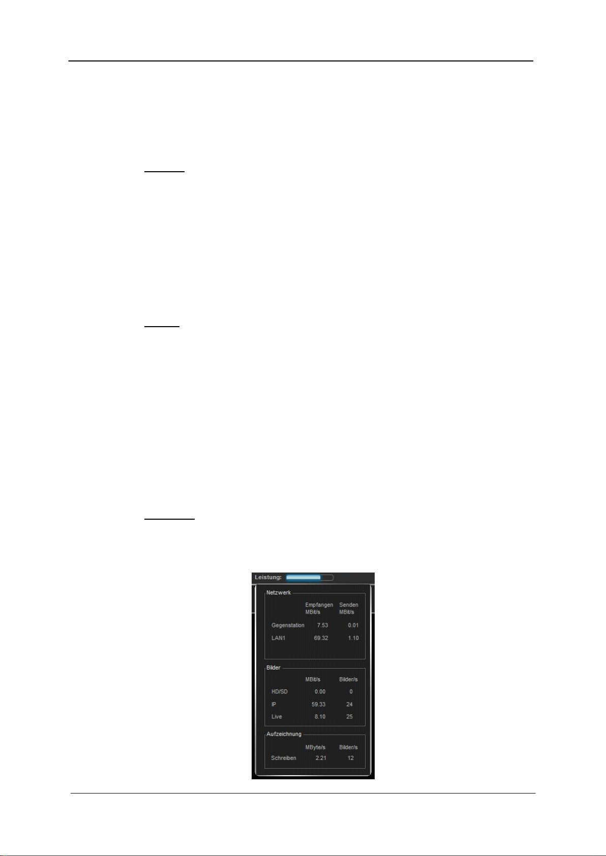
1.3.3 The network utilization indicator
The network utilization indicator displays the current utilization of the network adapter. If
you move the mouse over the indicator, a window showing the following information
opens:
Network
- Host:
Displays a host’s received and sent data volume in Mbits per second.
- LAN1:
Displays the first network card’s received and sent data volume in Mbits per second.
Important: For systems with two network connections, the display is divided into
LAN1 and LAN2.
Images
- HD/SD:
Shows the compressed data volume and the number of images of the analog
cameras.
- IP:
Shows the compressed data volume and the number of images of the network
cameras.
- Live:
Shows the decompressed data volume and the number of images in the live view.
Recording
- Write:
Shows the data volume and number of images written to the database.
Version 7.3 16
Page 17
ABUS VMS ABUS Security-Center GmbH & Co. KG
System manual
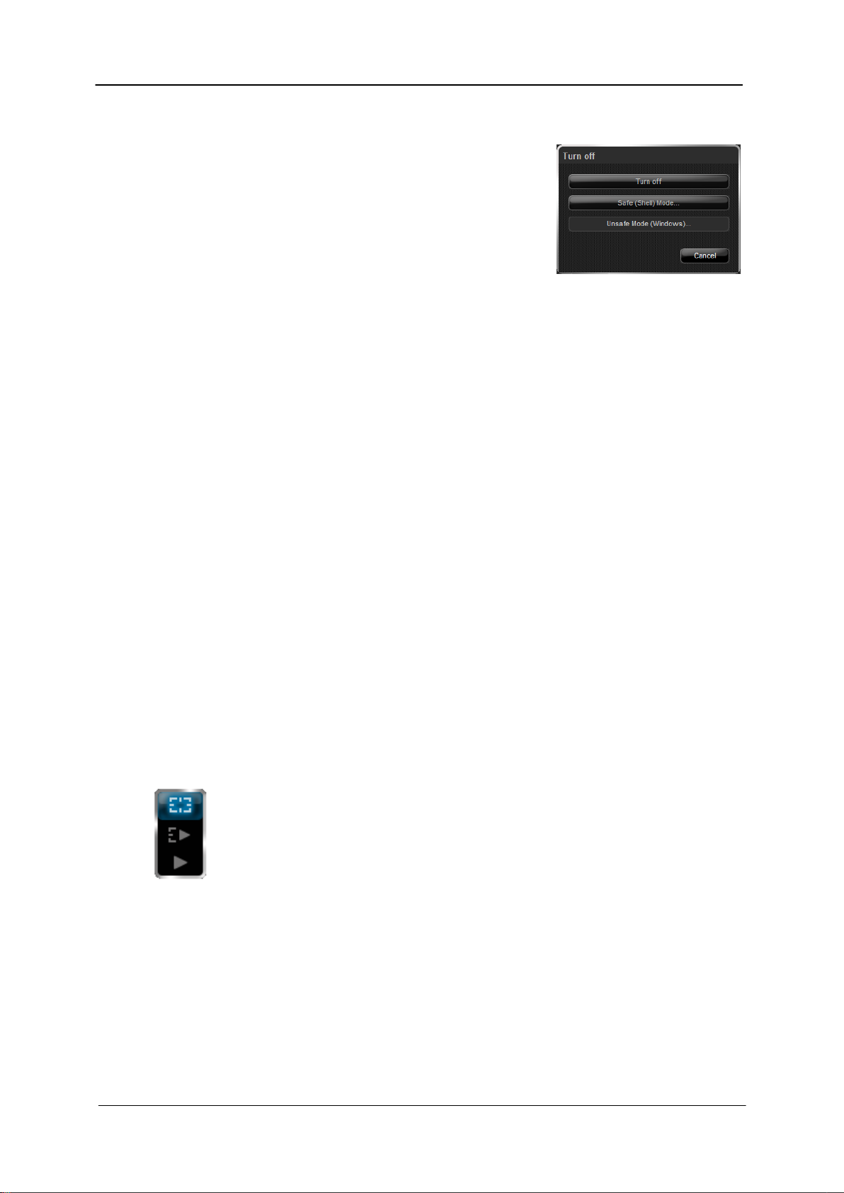
1.3.4 Logging out and exiting the software
To turn off the software, a logged-in user must first log out.
This is performed using the Logout button located in the
upper left-hand corner of the interface.
When the user has logged out, the button changes to Exit
and another click results in a dialog where the software
can be switched off.
However, to switch off the software, the user has to enter their user name and password
once again to prevent the video system from being accidentally shut down.
2. Software operation
Software operation is divided into several steps. This enables the user to better understand
the software and to apply it more effectively. In the following pages, you will become familiar
with the software’s basic operations.
2.1 Switching system modes
The slider in the lower left area of the screen determines the basic software functionality.
There are three categories, each one standing for a specific operating mode. These are
described in more detail further on in the manual.
When you switch to another mode, the system saves the current view in the background. This
view (camera positions) is automatically restored when you return to this mode.
Live mode
Live mode is used for viewing what is currently being monitored by the system’s
cameras. These can be cameras at the local station or at another host.
In addition, you can create favourites, generate connection and camera maps or
activate the sequencer in this mode.
It is not possible to access the database in Live mode.
Version 7.3 17
Page 18
ABUS VMS ABUS Security-Center GmbH & Co. KG
Buttons for forward or reverse playback
Activation of the camera
Activating the camera once again produces the
playback window
System manual
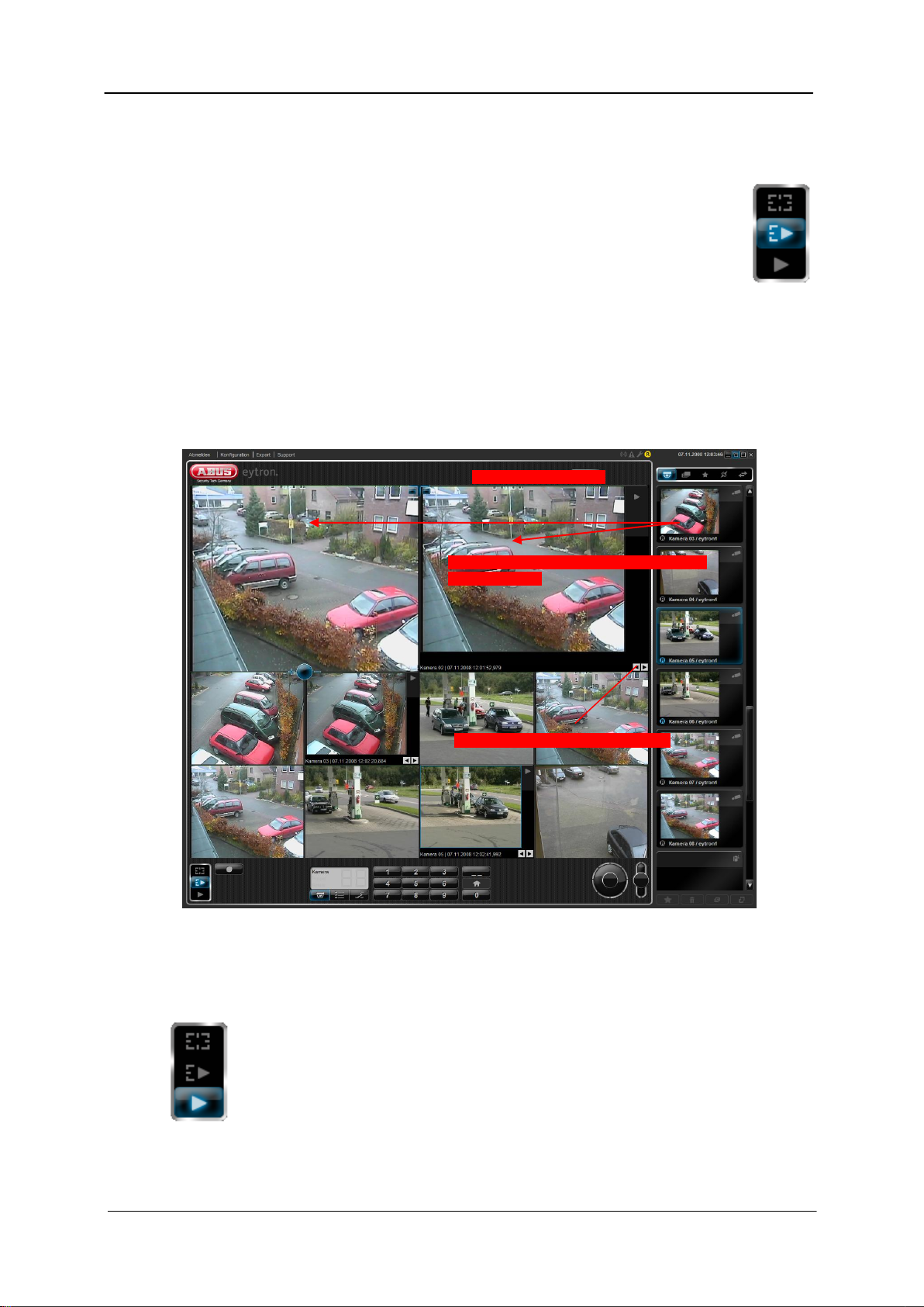
LivePlus mode
LivePlus mode is a combination of Live mode and Playback mode. Here, the user
is given the opportunity to start a playback of the database in addition to showing
the live cameras.
If an activated camera is placed in the live image window in this mode again, the
playback window for this camera is opened.
The playback buttons in the playback window can now be used for forward or reverse
playback.
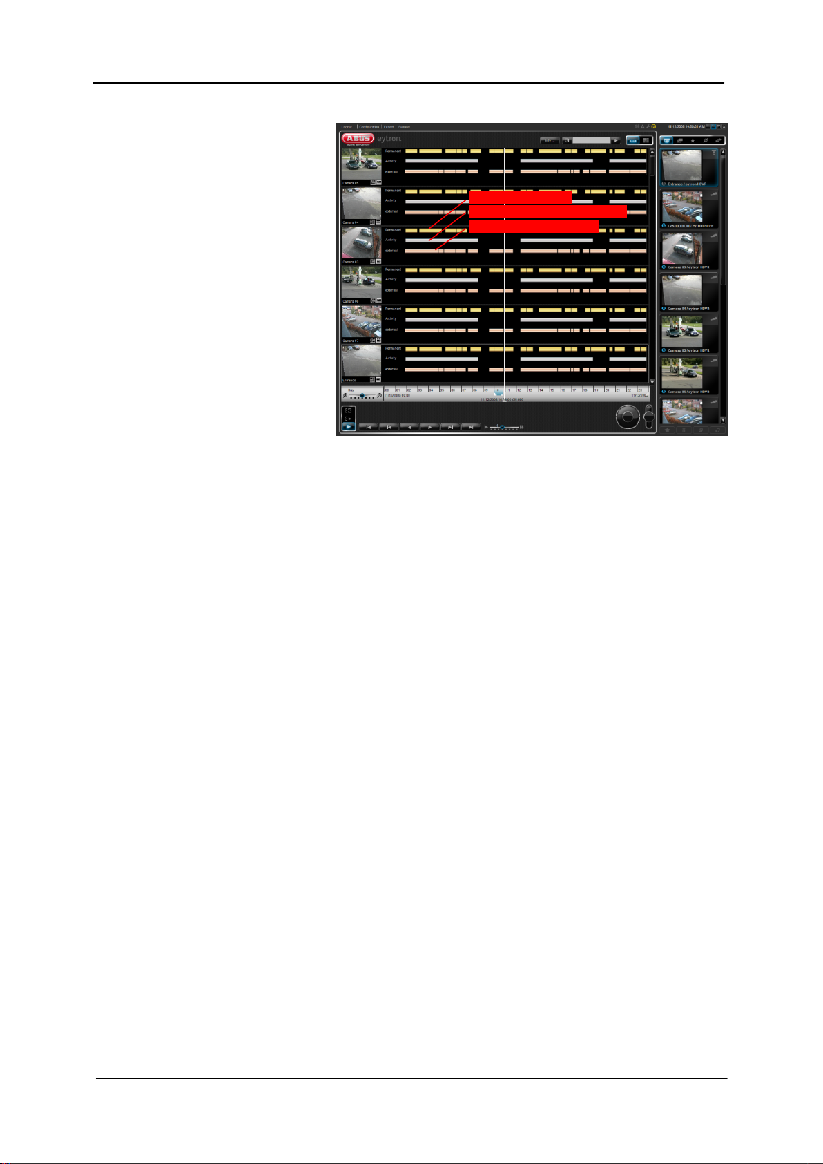
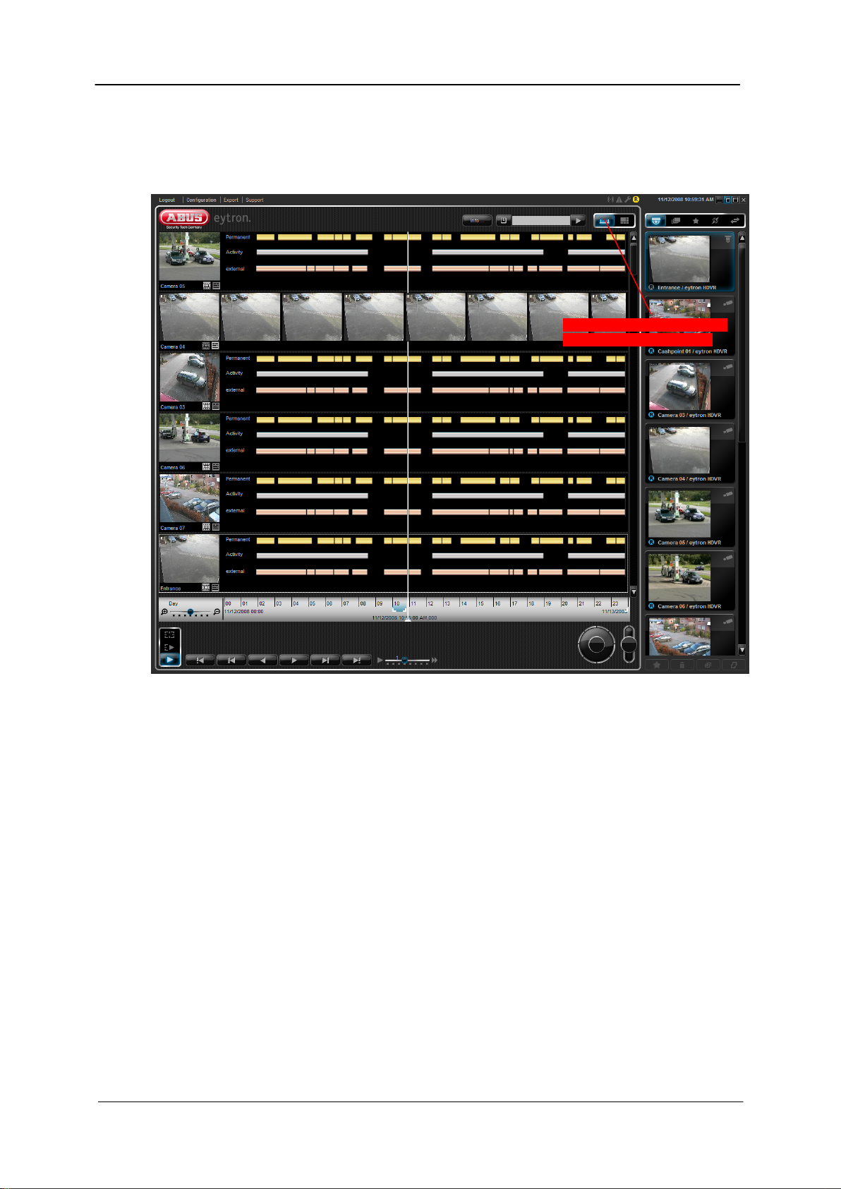
Playback mode
When switching to Playback mode, the keyboard at the lower edge of the screen is
replaced by the playback controls. A time stream is also added to the interface,
which is used for selecting when playback starts or defining the backup period.
Version 7.3 18
Page 19
ABUS VMS ABUS Security-Center GmbH & Co. KG
Permanent recording
Recording with activity detection
Recording of external data
System manual
All activated cameras are now transferred from Live mode to Playback mode and an overview
window with the current
recording statistics is
displayed.
This overview can be used
for showing the current
recording period with
permanent recording, as
well as recordings with
activity detection and
recordings of external data
(e.g. ATM).
Version 7.3 19
Page 20
ABUS VMS ABUS Security-Center GmbH & Co. KG
Switching between overview and
full-screen database playback
System manual
The bar view is used to show the current recording. There is a distinction here between
constant recording (yellow bar), recordings after activity detection (gray bar) and recoding of
external data (copper-colored bar).
The slider for starting the sequencer also has a new function in this mode. It is no longer used
here for starting the sequencer but for switching between the recording statistics (bar view)
and full-screen database playback.
If any cameras are already activated when the system switches to database playback, these
cameras are used for playback (synchronous playback).
The list of cameras (slides) is replaced by the list of all existing archives. The advantage of this
is that if a camera’s images are saved to more than one archive, they can also be activated
separately.
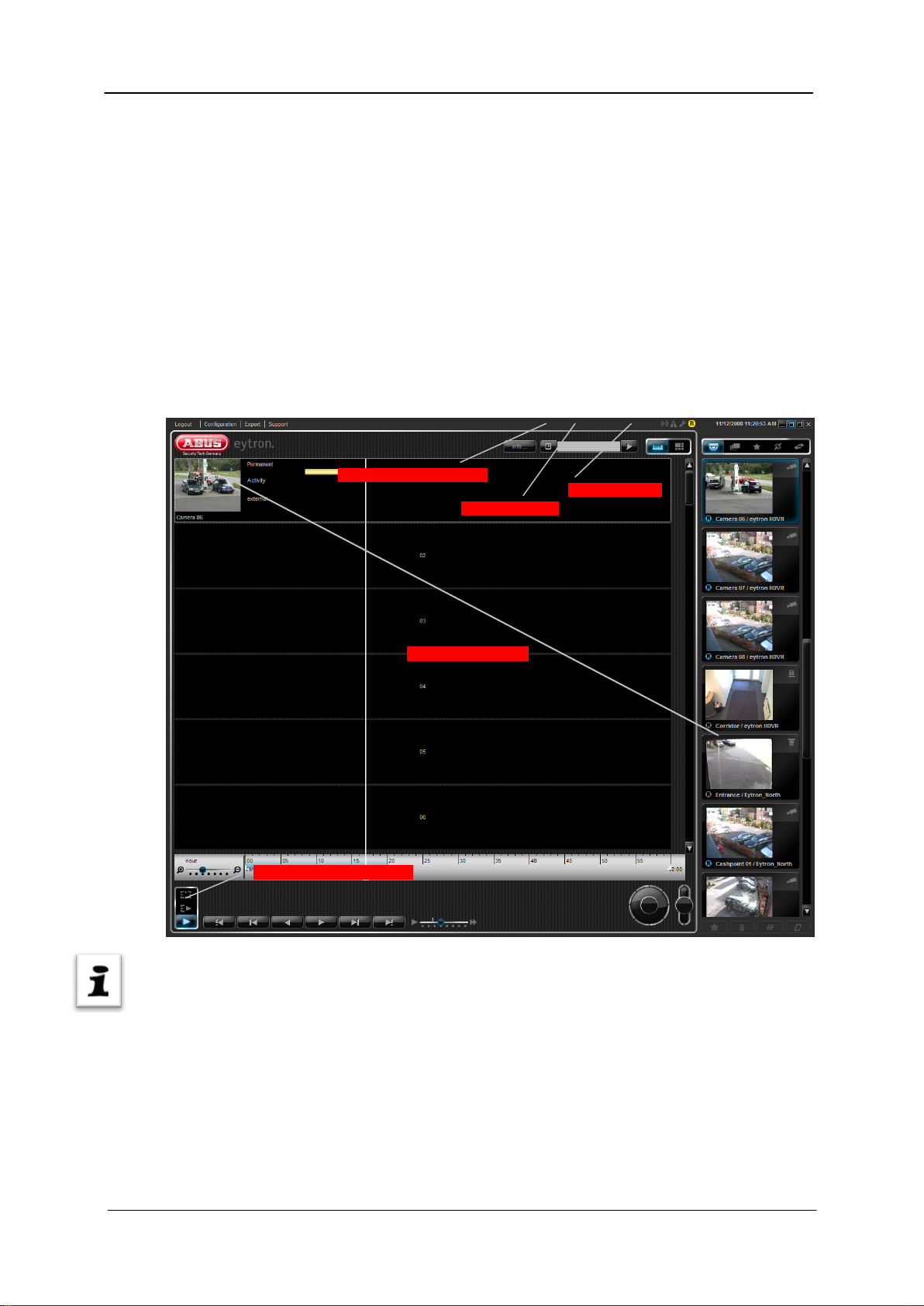
The view selector on the left of the timeline is for switching the current period for playback.
You can switch this between Year, Month, Week, Day, Hour and Minute. The timeline caption
(units) changes according to the position of the slider (see the illustration).
The start time controller defines the absolute start time. If the start time is to be a certain date
or time, move the slider to the required starting position by clicking and dragging it. Note that
you may have to first switch to a higher-level view (such as Month or Day) to select the
starting point.
Version 7.3 20
Page 21

ABUS VMS ABUS Security-Center GmbH & Co. KG
Jump to previous
event
One frame
backwards
Reverse playback
Forward
playback
Jump to next event
One frame
forwards
Playback buttons
Playback speed
Time bar
Slider for start time
View switch
Backup period
Calendar
Response: Search query
started
System manual
You can select the start time (date and time) directly using the calendar function. For example,
if you want to go directly to the end of the current recording you only need to open the
calendar and click Today. After you close the calendar, the slider for the start point jumps
directly to the current date and time.
Open the calendar by clicking the calendar button in playback mode.
The selected cameras can now be played back using the Forward and Reverse buttons. The
playback speed can also be set to between 1/20 and 40x using the speed controller.
The following graphic shows the meaning of the individual playback buttons.
When you use the Skip to next/previous event buttons, the
search query may take a moment longer. If so, an indicator
showing the current query status appears below the List view
camera display in playback mode. Once the database query is
complete, this indicator disappears again and the system skips
to the next event.
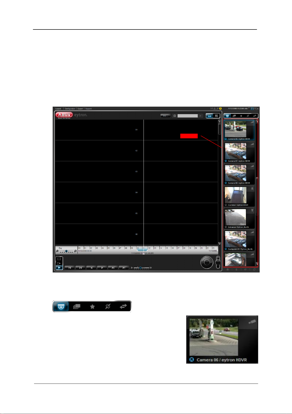
Note:
If there is no recording present for the period chosen, a blue
image with the caption “No video” is displayed instead of the video image.
Version 7.3 21
Page 22
ABUS VMS ABUS Security-Center GmbH & Co. KG
4. Enter search
2. Activate cameras
3. Select search criterion
1. Activate Playback mode
5. Start search
System manual
2.1.1 Using the search function
The search function provides quick and easy access to the stored data.
Possible search criteria include the time, date, ATM data (transaction number, bank sort code,
amount etc.), camera or detector name.
To carry out a database search, set the mode selector to playback.
Activate the cameras that you want to include in the search.
Use the search bar to select the search criterion (e.g. time).
Enter the time for the search in the field and click Start search.
Note:
When entering search criteria, no particular format is required. For example, if the search is for
a particular time, then this can be entered as a time (e.g. 23.15) or as a sequence of numbers
(2315).
If matching data is found, the slider for the start point jumps to the time entered.
Version 7.3 22
Page 23
ABUS VMS ABUS Security-Center GmbH & Co. KG
1. Activate Playback mode
2. Call up archive information
3. Select an archive to be deleted
4. Click Empty button
5. Answer Yes to confirmation prompt
System manual
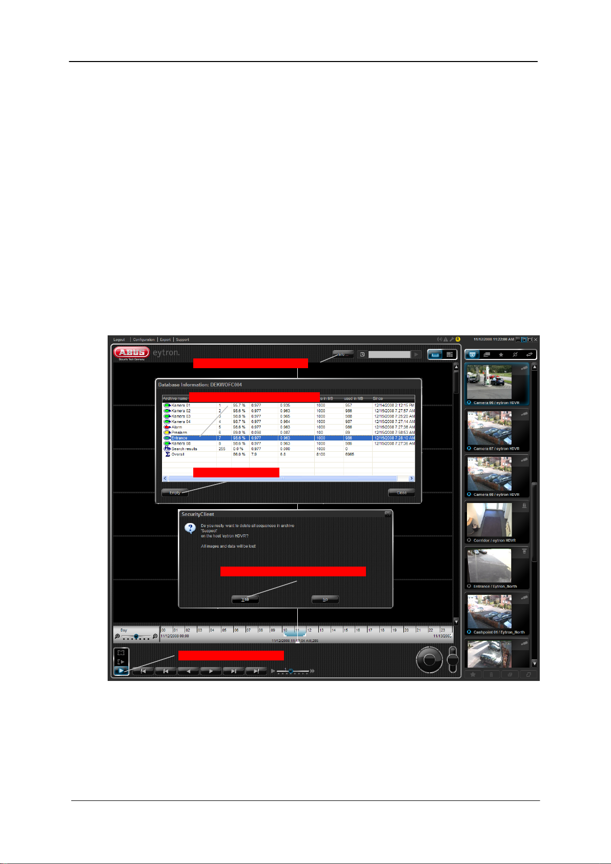
2.1.2 Voiding archives
If the image data saved in an archive is no longer needed, it is possible to void this archive.
To do this, switch the mode switch to Playback mode. The Info… button now appears on the
upper edge of the screen.
With this button, the operator can see how full the archives are in general and void individual
archives.
Highlight the archive that you wish to void and click the Empty button. Answer “Yes” to the
subsequent confirmation prompt.
This voids the archive.
Version 7.3 23
Page 24
ABUS VMS ABUS Security-Center GmbH & Co. KG
Slides bar
System manual
2.2 Switching the slide elements
The content of the slides bar is switched using the higher-level slider. This procedure replaces
the slides currently shown on the right-hand side with slides in the category selected.
For example, if the cameras category is switched to hosts, the camera slides are replaced with
slides from the available hosts.
The individual views are described in detail below.
Camera view
The “Camera” view is always the standard view for the
software. All activated cameras and connected hosts
are listed here. If, for example, the system is restarted or
exited, this is the view that is always shown to begin with.
It is also possible to obtain additional information from the
slide, such as the camera type, name and recording status.
Version 7.3 24
Page 25
ABUS VMS ABUS Security-Center GmbH & Co. KG
System manual
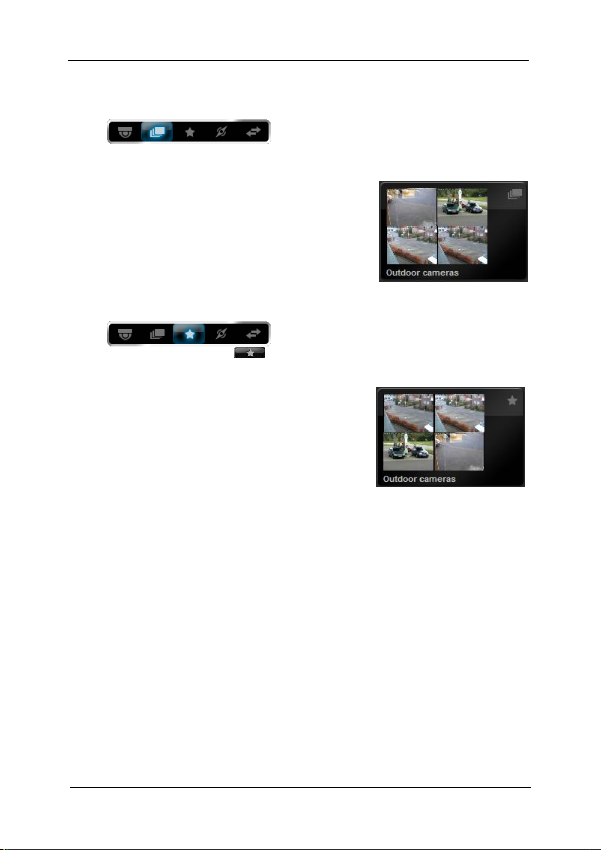
Camera group view
In the “Camera group” view, entire sets of cameras can
be activated at once. For example, if a camera group
referred to as “Outdoor cameras” is set up, all the empty windows in the live image area are
filled with the cameras from this group when the group is activated.
If there are more cameras in the group than can be
displayed in the live image area, the remaining cameras
are ignored.
Camera groups can be created in the system configuration
under Camera Camera groups (see 3.2.9 on page 73).
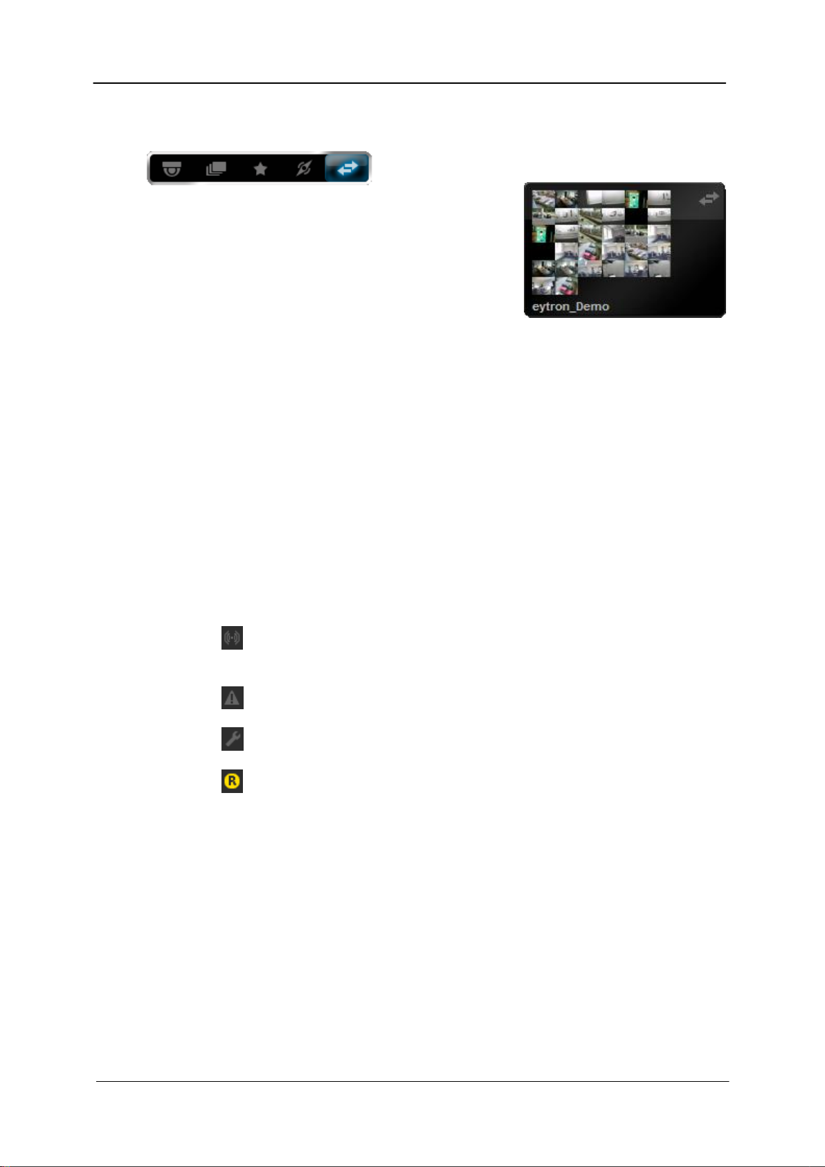
Favourites view
The “Favourites” view contains all the saved camera
favourites. These can be created and individually
named by any user with the button (on the bottom right-hand edge of the screen). This
generates a user-defined list of camera sets.
This facility is different from the camera groups because
the current view and image geometry are also saved
when favourites are created.
Furthermore, when a favourite is activated, the current
live window view is replaced by the view saved in the
favourites.
A detailed description on creating favourites can be found
under 2.6 on page 41.
Version 7.3 25
Page 26
ABUS VMS ABUS Security-Center GmbH & Co. KG
System manual
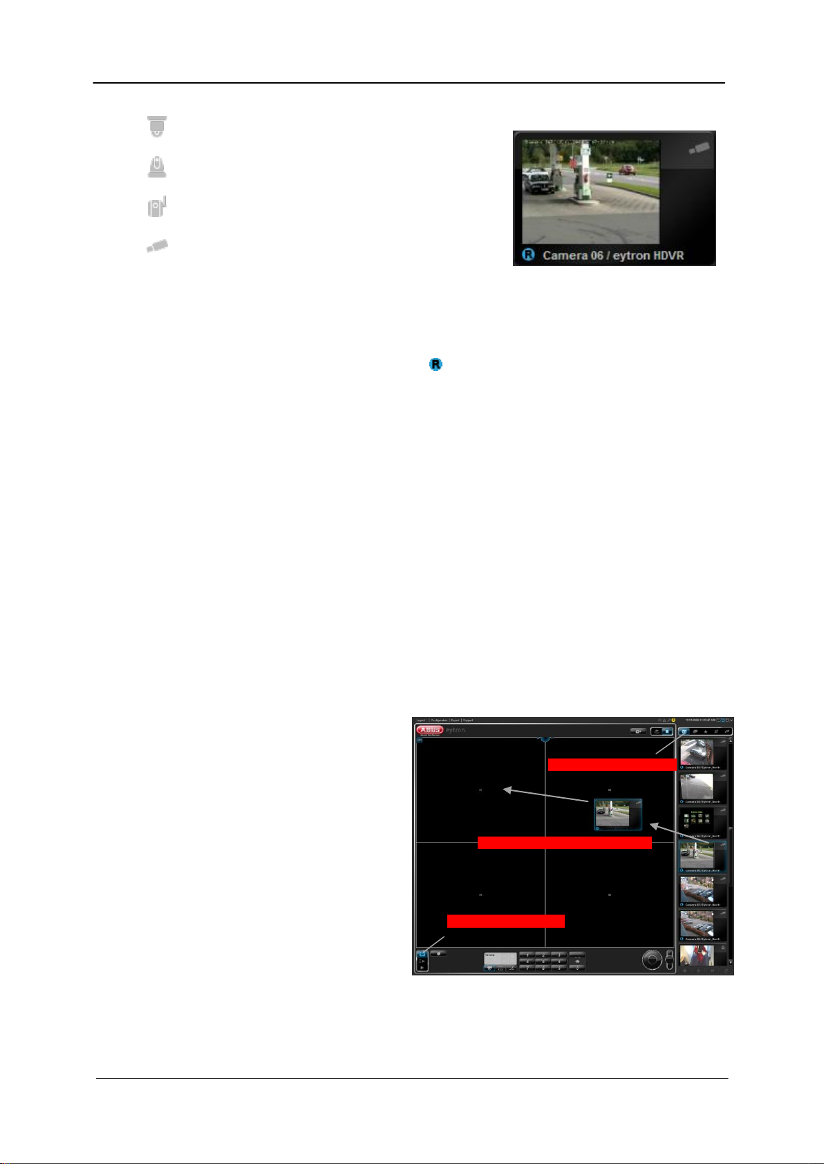
Host view
All the set hosts are listed in the “Host” view.
In this view, each host has its own slide showing a preview
of the local cameras on the host.
This view is always used to call up a host.
You can find further information on selecting hosts under
point 2.6 on page 42.
2.3 System status indicator
The current system status can be seen with the system status indicator. This is depicted by
four symbols.
These symbols are also located on the front of the ABUS HDVR / NVR housing, and use
LEDs to reflect the current system status.
The symbols are as follows:
Alarm (lights up as soon as an alarm is received (e.g. over an external
detector))
Fault (lights up if a fault occurs (e.g. camera failure))
Maintenance (lights up when maintenance interval is reached)
Recording (lights up as soon as video data is recorded)
The system status always relates to the local system only. It is not possible to display a
remote system status.
2.4 Working with the cameras
Providing they are set up in the system configuration, any cameras connected will be listed in
the Camera view. Each slide shown represents a camera.
The camera type is indicated by the camera symbol on the top right-hand side of the slide.
This can vary as follows:
Version 7.3 26
Page 27
ABUS VMS ABUS Security-Center GmbH & Co. KG
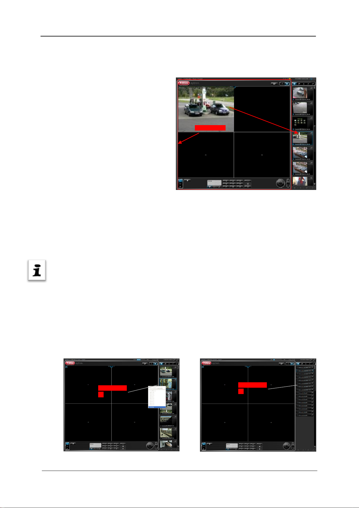
1. Activate Live mode
2. Activate camera view
3. Activate camera (drag and drop)
System manual
Pan/tilt camera
Pan/tilt camera with network connection
Network camera or video server
Analogue camera
The camera name and host name are always displayed at the bottom of the slide. It is
therefore very easy to assign the listed cameras to the relevant host.
If the camera is recording, the Record symbol appears in the slide.
Information on setting up further cameras can be found under 3.2 on page 51.
2.4.1 Activating and deactivating the cameras
Simply drag and drop a camera into a free live window to activate (switch on) the camera.
Switch the mode switch to Live mode (step 1).
Next, switch the view switch to the Camera view (step 2).
In the Camera view, click the slide of the camera and keep the left mouse button pressed.
Now move the mouse to a free camera window and release the left mouse button. The
camera is then embedded in the window (step 3).
If you wish to embed the camera in
another window, you can again use the
drag and drop function to move the
embedded live image to another window.
If an activated camera is moved to an
occupied window, then the cameras
swap positions on the screen.
If a camera from a camera list is
released over an occupied window, the
existing video image is replaced with the
image from the new camera.
Version 7.3 27
Page 28
ABUS VMS ABUS Security-Center GmbH & Co. KG
Chrome frame
Slide preview
on
Slide preview
off
System manual
To deactivate (switch off) a camera, simply release the camera outside the chrome frame
using drag and drop. We recommend dragging the camera back to the slides list.
Camera groups or favourites can be
used to activate more than one camera
at the same time.
From version 7.3 onwards, you can reposition the individual slides using the drag and drop
method. Your individual user settings are saved each time you log off.
As well as this, you can activate a camera by double-clicking the corresponding slide.
Note:
Each camera can only be displayed once on the screen at all times. This applies to each
screen in multi-monitor operation. Depending on your particular version, a camera can be
displayed up to four times in Live mode.
If there are very many cameras in the list, the preview image on the slides may be disabled.
This is to provide a better overview when one receiver. for example, is connected to several
hosts.
To disable the preview image, right-click a slide in the list and select Preview in the context
menu. You can enable or disable the preview at any time using the context menu.
Version 7.3 28
Page 29
ABUS VMS ABUS Security-Center GmbH & Co. KG
Camera puck
Geometry tool
System manual
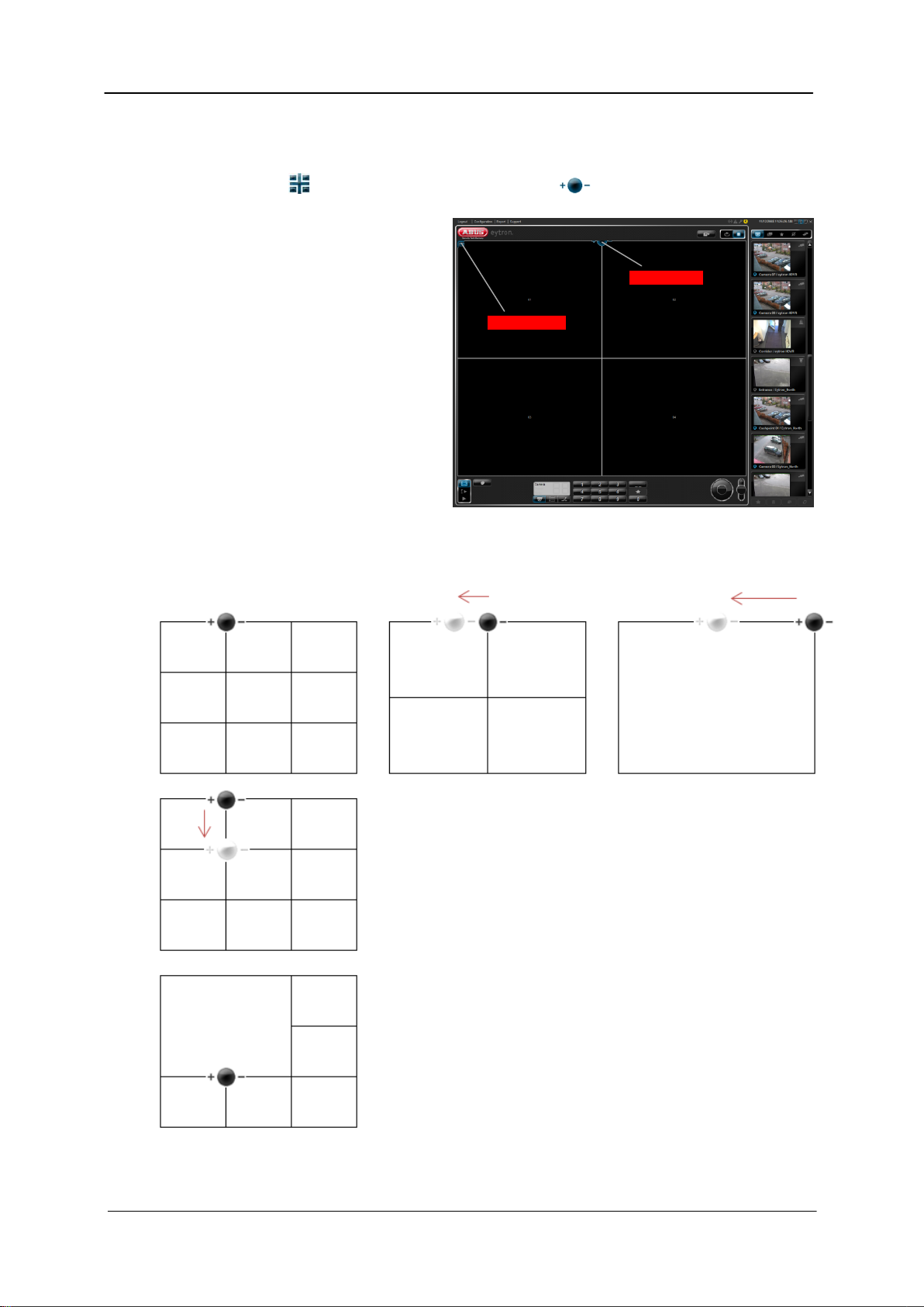
2.4.2 Switching the image geometry
The ABUS VMS software has two tools to switch between camera views. The first of these is
the geometry tool and the second is the camera puck .
By changing the position of both tools
relative to each other, a total of 72
views in 4:3 and 72 views in 16:10 can
be displayed. The views are only
switched once the mouse button is
released.
The set view is saved when you exit the
software and is automatically
reproduced when the software is next
started.
A more detailed description on how to
use these tools can be found below.
Working with the camera puck:
The camera puck is used to increase and decrease the
number of camera windows. For example, if more free camera
places are required, the puck must be moved along the
horizontal plane towards the plus sign (in quadratic view).
If the puck is moved along the vertical plane, the current view
is changed to the 1Plus view. The further the puck is now
moved away from the geometry tool, the larger the 1Plus
window.
If more free windows are required again, then these can be
created by moving the puck along the horizontal plane (+/-).
Version 7.3 29
Page 30
ABUS VMS ABUS Security-Center GmbH & Co. KG
Reflecting the current view
Displaying the 2Plus view
System manual
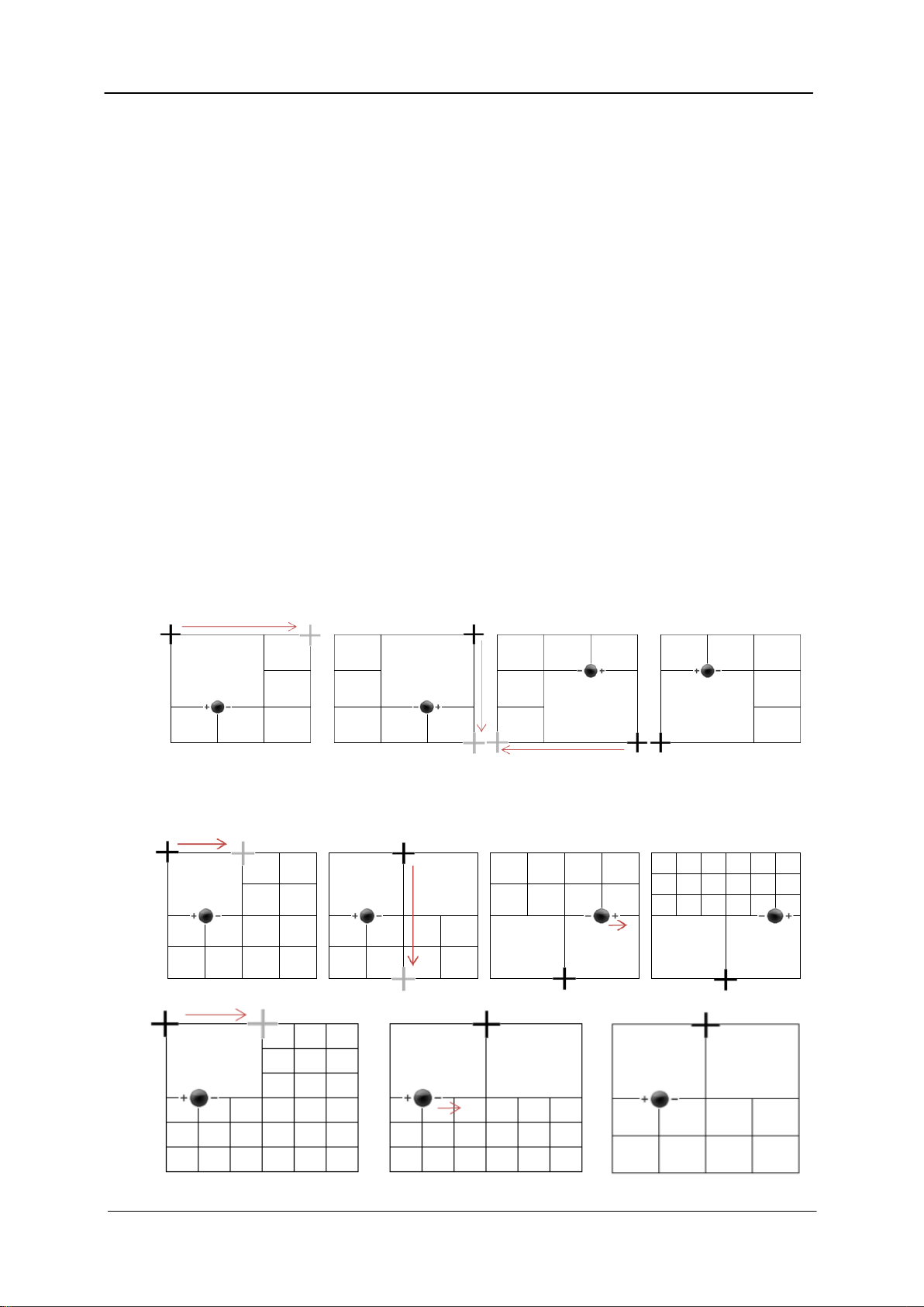
Working with the geometry tool:
The geometry tool is used for displaying the Quadratic, 1Plus and 2Plus views as well as
reflecting the current view.
If the geometry tool is in one of the corners of the live window, the Quadratic and 1Plus views
can be displayed with the camera puck.
If the tool is positioned in the centre and on the edge of the live window in the horizontal or
vertical plane, then the 2Plus view is shown. However, it is not possible to switch to 2Plus
mode from every view.
To activate the 2Plus view, proceed as shown in the illustration Displaying the 2Plus view.
The current view can be reflected by moving the geometry tool to the opposite side.
The 2Plus view can only be displayed from a symmetrical 1Plus view.
Version 7.3 30
Page 31

ABUS VMS ABUS Security-Center GmbH & Co. KG
Cameras
Relays
Presets
LCD display
Home
Number keys
Two-digit
mode
Tours
System manual
This means that the system can only switch to 2Plus mode if the first 1Plus window can fit next
to it again.
2.4.3 Using the zoomstick
The zoomstick on the lower right-hand edge of the screen is used to
control pan/tilt cameras.
This allows the direction of the cameras to be variably adjusted
(horizontally, vertically and diagonally).
However, only the camera currently selected can be directed in this way. This is shown by a
red frame in the live window.
To direct another camera, left-click that camera’s live image in the live window section.
Alternatively, the camera can be selected with the numeric field. To do this, the number of the
camera to be activated must be entered.
The current image section can be enlarged by means of the zoom controller. If a pan/tilt
camera has been selected, the camera’s analogue zoom is used. With fixed cameras, the
image is zoomed in on digitally.
You can then move the enlarged section of the image using the arrow buttons.
2.4.4 Using the numeric field (keyboard)
The numeric field can be divided into four separate modes of operation. These are camera
selection, selection of pan/tilt presets (saved camera positions), selection of tours and relay
activation.
The current selection is shown in an LCD display.
The input mode can be changed
to two digits using the button. The
operator can therefore choose from up
to 99 entries.
You can call up tours 1 to 8 of analogue cameras by clicking the button. You can also
open and use the on-screen display (OSD) of each analogue camera.
The (Home) key moves the pan/tilt camera back to its starting position. This is
particularly useful if a camera has been moved and the operator no longer knows its starting
position.
Version 7.3 31
Page 32

ABUS VMS ABUS Security-Center GmbH & Co. KG
1. Activate pan/tilt camera
2. Define image section
3. Switch keyboard to preset
mode
4. Activate double-digit
mode
5. Enter first digit
6. Enter second digit and hold
down key
7. Confirmation of saved preset
System manual
2.4.5 Saving camera positions (presets)
The presets can be used to save and call up specific positions for pan/tilt cameras. Presets
are saved by pressing and holding down a number key while preset mode is activated (see
Fehler! Verweisquelle konnte nicht gefunden werden.). You then receive confirmation on
the live image of the camera (e.g. Preset 1 has been set).
Note:
The message that the preset has been saved does not appear until the command has been
sent to the camera. This can sometimes take up to 10 seconds.
If you save more than nine presets, click the button to move to double-digit mode.
Then save the preset by pressing and holding the number key after entering the second digit.
Example – saving present number 12:
Version 7.3 32
Page 33

ABUS VMS ABUS Security-Center GmbH & Co. KG
Images moved line by line in quadratic view
Image swap when all
the cameras are
displayed in a high
Image swap when all
the cameras are
displayed in 1Plus view
Manual recording On
Manual recording Off
System manual
2.4.6 Using the sequencer function
The sequencer is used to display all the cameras in the camera list one by one.
It does not matter whether the cameras are in a local or remote system in
this case.
The sequencer can be influenced by changing the image geometry. For example, if you are in the
quadratic view (4, 9, 16, 25 or 36 cameras), all the live image windows are moved upwards line by line
(see graphic). If the height of the view has been set in such a way that all the cameras can be shown
at once, the sequencer swaps the positions of the images.
If 1Plus view is activated, the
cameras in the small windows
are swapped in succession
with the large window.
The default sequencing
interval is 5 seconds.
Note:
Sequencers can only be activated in Live and LivePlus mode. If the software is in Playback
mode, the slider is used to switch between database playback and recording statistics and the
sequencer is deactivated.
2.4.7 Using manual recording (Panic Record)
Activating the Manual recording button ensures that recordings are made from all the currently
activated cameras. This occurs until the button is switched off again or Playback mode is
selected.
It is then possible to watch the recordings in Playback mode.
For each camera that was active during recording, there is now a recording in that period. This
is shown in the recording statistics.
Version 7.3 33
Page 34

ABUS VMS ABUS Security-Center GmbH & Co. KG
System manual
2.4.8 Using the alarm lists
The alarm lists help users to monitor detector activity. If an alarm list has been created in the
database settings, it can be linked to any detector. Every time a detector is triggered, an entry
is generated in the alarm list.
Configuration
To create an alarm list, open the system configuration and set the view selector to
Database/saving (see section 4).
In the list on the left, select Archive and click New to create a new archive.
Give the archive an unambiguous name and specify the required memory size.
Finally, select the archive type Alarm list and save the settings. The alarm list has been
created.
In order for entries to be generated in the alarm list, you must activate the required detectors
and link them to the alarm list using the Activations item. For more information see section 3.5
on page 102 and section 3.4.9 on page 98
Use
If an alarm list has been configured in the system, it
appears as a slide in the camera view. Like the cameras
and recordings, you can activate the alarm list using your
left mouse button (see section Fehler! Verweisquelle
konnte nicht gefunden werden. on page Fehler!
Textmarke nicht definiert.), by dragging it to a free
camera window.
Note, however, that the alarm lists can only be activated in
full-screen and list view playback mode.
If there is another free field below the camera window (in full-screen mode), the alarm list
always occupies two windows at the same time. This gives you a clearer view for evaluating
the entries. If not, it is only displayed in one window. Use the following illustrations for this.
Version 7.3 34
Page 35

ABUS VMS ABUS Security-Center GmbH & Co. KG
System manual
Free field available No free field available
The alarm list also gives you the option of filtering the entries using two checkboxes. These
are for the motion alarms (activities) and external alarms (detectors).
If the alarm list is activated in list
view playback mode, you will
see statistical summary of the
alarms that have been triggered.
Motion alarms are shown in gray
and alarms from external
detectors in copper-color.
Virtual alarms and the detector
inputs on the alarm card can be
used as external detectors.
Clearing alarm lists
If the entries in the alarm lists are no longer needed, you can clear them by clicking the Info
button (in playback mode). However, only users with the appropriate authorization can do this.
For further information on see section Fehler! Verweisquelle konnte nicht gefunden
werden. on page Fehler! Textmarke nicht definiert..
Version 7.3 35
Page 36

ABUS VMS ABUS Security-Center GmbH & Co. KG
1. Activate Playback mode
2. Activate cameras
3. Select backup period
4. Export data
System manual
2.5 Creating backups
The backup dialog can be called up easily using the Export button on the top left-hand edge of
the screen. Single-frame export, AVI export and database export are possible. In addition, you
can print out individual frames or send them by e-mail.
There is a difference between local and remote backup. The variations are explained in more
detail below.
2.5.1 Local backup (database export)
A local backup saves the recorded video data from the local system onto external media.
These include USB sticks, CD/DVD or an export to a separate directory.
To export the video data, insert a disc in the DVD burner or attach a USB stick.
Change to Playback mode and activate the cameras to be used for the backup. When doing
so, make sure that only the cameras to be backed up are activated, as otherwise any cameras
not needed will also be backed up.
Specify the time period to be backed up using the selection tool and click the Export button.
The Export dialog is now
started in the Database
export view and the
archives selected from the
list are displayed. The
selected backup period is
also taken from the client
and updated in the list.
If the operator wishes to
use another name for the
backup, this can be
entered in the Name of
backup field.
In the Export dialog, select
the drive to be used for the
backup. If the drive is not listed here, you must first set it up in the system configuration
(Database/Storage Drives) as Backup read & write (see point 3.3.1 on page 69).
Version 7.3 36
Page 37

ABUS VMS ABUS Security-Center GmbH & Co. KG
5. Enter name (optional)
6. Select storage drive
7. Start backup
Select AVI export view
System manual
When all the settings have been made, the
backup can be started using the Export
button.
The reader software is also automatically
copied on to the storage medium at the end
of the backup process (database export
only). This enables the image data to be
viewed on any Windows PC (Windows XP
and higher).
Compared to the main software, use of the
reader software is highly limited. Only the
database playback functions are
implemented.
If the data was backed up on CD or DVD, the
reader software is automatically started
immediately after the disc is inserted.
2.5.2 Local backup (AVI export)
The AVI export enables the recorded image data to be exported in a video format. This can
then be played back using a normal media player. Reader software such as that used for
exporting a database is not needed for playback.
If your program has difficulty playing the
data, check that a corresponding codec for
DivX or XVid (e.g. K-Lite codec pack) is
installed. Further information can be found in
the manual of the media player.
The procedure for exporting video data is
the same as described under 2.5.1 except
that Database export (point 2) is selected
instead of AVI export (point 3) in the backup
dialog.
If more than one camera is activated during
backup, a separate video file is created for
each of these cameras.
Version 7.3 37
Page 38

ABUS VMS ABUS Security-Center GmbH & Co. KG
1. Activate host view
2. Connect to host
3. Activate Playback mode
System manual
2.5.3 Remote backup
The remote backup enables image data from a connected host to be backed up.
However, the host must be connected before the backup dialog is opened.
Switch the view switch on the client interface to the Host view and select a host (further
information on selecting hosts can be found under point 2.7 on page 44).
Now change to Playback mode and activate
the cameras of the host to be used for the
backup. Ensure also that no other cameras
are activated, otherwise they will be backed
up as well.
Perform all further steps as described under
point 2.5.1 (local backup).
A combination of cameras from the local
station and host is also possible.
2.5.4 Single frame export (storage, printing, e-mailing)
The single frame export can be used to save, print out and e-mail single frames from the
database or live image display.
If needed, the station name, camera name and date and time can be shown in the image
directly.
The possible settings available here are described in more detail below.
Storing single frames:
To export single frames, open the export dialog at the top left-hand edge of the screen in the
client interface and switch the export mode to Single frame export (point 1).
The image to be exported is now displayed as a preview.
Select the file type and check the “On screen display” box if the camera name, date and time
are to be contained in the exported image.
Version 7.3 38
Page 39

ABUS VMS ABUS Security-Center GmbH & Co. KG
2. Select file type
4. Change file name and storage location if necessary
1. Select single frame export view
3. Activate “On screen display” (optional)
5. Start export
System manual
The default folder for the images is
the My Pictures folder. If you wish to
save to another location, you can
use the Browse button.
Click the Export button to start
exporting. The image is now saved
to the location selected and the
export dialog is closed again.
Repeat the above steps to export
further single frames.
Sending image data to a printer:
If you wish to send single frames to a printer, you only need to select printer export (point 4)
instead of the single frame export (point 1) in the export dialog.
If necessary, the printer can be changed
with the Printer setup button.
Click the Export button to send the image
to the printer.
If a printer has not yet been set up, the
Windows wizard appears for setting up a
new printer. Follow the wizard’s
instructions for adding a new printer.
Otherwise, select the printer to be used
and click the OK button.
The image is now sent to the printer.
Note:
The operating system for the ABUS HDVR is on a CompactFlash card. The available memory
on the C:\ drive is therefore greatly reduced. When adding another printer, please only install
the printer drivers and not the image editing programs or printer management tools.
Version 7.3 39
Page 40

ABUS VMS ABUS Security-Center GmbH & Co. KG
System manual
Sending image data by e-mail:
In addition to e-mail notification (see point 3.7.5.1 on page 124), you can now also send the
image data by e-mail.
To send an e-mail, switch to Playback mode. Activate the camera to be used for the e-mail
and open the export dialog.
Note:
If more than one camera is activated in Playback mode, the export only applies to the active
camera. The active camera can also be selected by clicking the preview image.
Switch the option switch to E-mail Export (point 5) and click the Export button. However, an email client (MS Outlook or Outlook Express) must be installed to send the images.
If no e-mail client is installed, the e-mail cannot be
exported. You will then receive an error message
stating that the mail system cannot be loaded (see
graphic).
If an e-mail client is found, it is started and the
individual frame is attached to the e-mail.
Complete the message by adding a recipient’s
address, subject and a message text (where necessary).
Version 7.3 40
Page 41

ABUS VMS ABUS Security-Center GmbH & Co. KG
System manual
Click Send to send the e-mail.
2.6 Creating favourites
When using several cameras in the ABUS VMS software, it is recommended to save certain
camera views as favourites.
To display the camera again, only the favourite needs to be activated instead of each
individual camera.
Another advantage is that the set image geometry is also saved when favourites are created.
The following steps are necessary when creating favourites:
- Switch the system to Live mode
- Set the desired image geometry (see point 2.4.2 on page 29: “Switching the image
geometry”)
- Activate the desired cameras and define the sequence in the live window
- Switch the view switch to the Favourites view (point 3)
- Create the favourites using the Create Favourites button
- Assign a name for the favourite to be saved
Version 7.3 41
Page 42

ABUS VMS ABUS Security-Center GmbH & Co. KG
1. Switch to Live mode
2. Set image geometry
3. Activate camera
4. Switch to Favourites view
5. Create favourite
6. Name assignment and saving the settings
System manual
Version 7.3 42
Page 43

ABUS VMS ABUS Security-Center GmbH & Co. KG
System manual
After the favourite has been saved, a new slide is added to the favourites list.
When this slide is now dragged into the live window, then the image geometry is changed
according to the saved view and the cameras are displayed according to the defined
sequence.
In doing this, the existing cameras are replaced.
Note:
Favourites are created separately for each user. This means that favourites cannot be seen by
other users when in multiple-user mode. No supervisor rights are needed for the creation of
favourites.
2.6.1 Deleting favourites
If stored favourites are no longer needed, then they can be deleted using the button.
Switch to the Favourites view and select the slide to be deleted, then click the Delete button.
The favourite is then deleted from the list.
Version 7.3 43
Page 44

ABUS VMS ABUS Security-Center GmbH & Co. KG
1. Drag the host slide into the live window
2. Double-click the host slide
3. Select the host, then click on the Connect button.
System manual
2.7 Connecting to a host
You can connect to hosts over the Host view in the interface when hosts have already been
created in the system configuration.
To do this, switch the view switch to the Host view.
There are three different ways of connecting to a host. Connection is made in the following
circumstances:
1. When the host slide is dragged into the live image area (drag
and drop).
2. When the host slide is double-clicked.
3. When the host slide is selected and the Connect button is
clicked.
In each of these cases, the progress of the connection is shown in a dialog.
When the connection has been established correctly, the software switches from the Host
view to the Camera view. The cameras of the host are now added to the list and can be
activated in the same way as the local cameras.
To disconnect the host, press the button (Disconnect) in the Host view. To do this, first
select the desired host (host slide) from the list, then click on Disconnect.
Information on setting up other hosts can be found under point 3.7.3 on page 121.
Possibilities of connecting
hosts
Version 7.3 44
Page 45

ABUS VMS ABUS Security-Center GmbH & Co. KG
Number of attempts to connect to the host
Interval between attempts
Non-connected
hosts
Connected
hosts
System manual
If the connection has been successfully established, the software switches from the host view
to the camera view. The cameras of the host are now added to the list and can then be
activated in the same way as the local cameras.
If you want to disconnect from the remote station, you can do this by
clicking (Disconnect) in the Host view. To do this, first
highlight the host (the slide representing it) in the list and then click
Disconnect.
Hosts that are already connected appear on the host screen with a
host icon lit up.
For more information on connecting additional hosts, see section
3.7.3 on page 121.
2.7.1 Automatically redialing hosts after the connection is interrupted
If hosts are connected via the internet or DSL, the ISP (Internet Service Provider) may
sometimes automatically disconnect every 24 hours (DSL forced disconnection).
This disconnection also interrupts the
connections to the hosts.
The system therefore features an
automatic redial function for reconnecting
to the hosts within a defined period. You
can set this up in the system
configuration under Network Hosts.
Specify the number of automatic redial
attempts and the intervals between them.
Once you save and apply the settings,
the function is activated.
Note:
Automatic redialing must be set up separately for each host.
Because the IP addresses change after every forced disconnection, they have to be updated
each time in the host settings. We recommend replacing the IP addresses of the hosts with
what are known as DynDNS addresses. The update then takes place automatically.
Version 7.3 45
Page 46

ABUS VMS ABUS Security-Center GmbH & Co. KG
Host(s) to be used
Number of configured cameras
Cameras with reference image
Live
Reference
Start comparison
Delete unit
Image OK
Image not OK
Current status display
System manual
2.8 Reference image comparison
The reference image comparison allows users to compare the current camera image with a
reference image stored in the system. This means that any tampering with the cameras, for
example turning them around, can be quickly detected. The result of this comparison is then
documented in an HTML report any saved in the My Documents folder of the current user.
To start the reference image comparison, first open the Info dialog by clicking Support. You
can then start the comparison by clicking Reference images… .
Note:
A reference image comparison is only possible for cameras that are set up in the system for
creating reference images and if reference images have been created. For more information
see section 3.2.7 on page 60.
After the window has loaded, all the configured hosts are connected and the number of
activated cameras, as well as the cameras with reference images created, are shown in
parentheses. If a host is not reached within 60 seconds, its status is changed to Connection
failed. This host is then no longer included in the reference image comparison and can be
deleted.
If the reference image comparison is not carried out for all the listed hosts, then the hosts that
are not included must be deleted. Highlight these hosts and click Delete.
Version 7.3 46
Page 47

ABUS VMS ABUS Security-Center GmbH & Co. KG
System manual
To start the comparison, click Start. All cameras of the hosts activated for the reference
image option are shown in succession.
The user must then compare each image with the reference image and decide whether the
two images match. If they do, click OK to confirm the image. If not, click Not OK
to mark the image as incorrect. This is documented later in the report.
Once the comparison has been completed, the system generates an HTML report and
displays it in the web browser. You can print the report out if required.
If several hosts are included in the reference image comparison, the overall results are
summarized in a single HTML report.
The following illustration shows a finished HTML report where one camera has been
evaluated as OK and the other camera is Not OK. The user making the comparison must print
out and sign the document, and file it as required.
Note:
A report is saved in the My Documents folder of the current user for each reference image
comparison. The folder name is “ReferenceView_(date)_(time)”, (for example
ReferenceView_20090101_0900). Because this generates large amounts of data, the user
must manage these reports and, if necessary, delete old reports and those that are no longer
required.
The reference image comparison is implemented in software version 6.5 and higher, and is
limited to the VMS Enterprise version.
Version 7.3 47
Page 48

ABUS VMS ABUS Security-Center GmbH & Co. KG
System manual
2.9 Shell mode (safe mode)
The shell mode prevents access to the operating system by setting the user interface modally
at the front of the system. This means that the system is prevented from possible
manipulation. The following points show how to activate and deactivate the shell mode.
2.9.1 Activating the shell mode
To activate the shell mode, a logged-in user must first log
out. To do this, use the Logout button (in the menu bar at
the top-left of the screen).
Click on the Switch off button, then select Safe (Shell)
Mode in the switch-off dialog.
For security reasons, you are then asked whether the
program should really be started in shell mode or not.
Confirm this dialog by pressing Yes.
After entering the user name and password, the system is automatically restarted and the
shell mode is activated.
2.9.2 Deactivating the shell mode
To deactivate the shell mode, proceed as described in point 2.6.1. The only difference here is
that the Unsafe Mode (Windows) button is pressed instead of the Safe (Shell) Mode button.
After the user data is entered, the system is restarted in unsafe mode and the Windows
interface can be used again.
Version 7.3 48
Page 49

ABUS VMS ABUS Security-Center GmbH & Co. KG
View switch (Cameras, Database, Digital I/O, Actions, Network, Security and Miscellaneous)
Delete
New
Undo
Host
Disconnect
Host
Connect
Restart system with changed
settings
Saving the
settings
Menu bar
Date/time
System manual
3. System configuration
The system configuration is used to set up the entire system. For example, you have the
possibility of creating new users or configuring connected cameras here.
A more detailed description on how to use the system configuration can be found below.
When configuring the system, ensure that the individual components are set up carefully in
order to prevent possible malfunctions.
Version 7.3 49
Page 50

ABUS VMS ABUS Security-Center GmbH & Co. KG
Camera
Digital
o
Database
Network
Security
s
Drives
Database fields
Archive
Automatic backup
1. ISDN
2. ISDN
TCP/IP
SMS account
E-Mail
Hosts
RTSP server
Auto Logout
Windows Login
Security guidelines
Permissions
Users
Joystick
Language settings
Maintenance
Multi-monitor
Miscellaneous
IP cameras
Analogue cameras
Camera groups
SimUnit
ATM / POS
Relays
Detector list
CASA10010
Storage
Calls
Guard tour
Video output
FTP upload
Notifications
Timers
Activations list
System configuration
System manual
3.1 Opening the system configuration
The system configuration is opened using the Configuration menu point at the top-left corner
of the user interface screen.
Access is only permitted for authorised users (entry of user name and password). To log in,
use your existing user data.
Access to the system configuration can be adjusted for each user individually using the
“Permission” levels (see point 3.6.1 on page 111).
The following graphic shows the schematic structure of the system configuration:
Version 7.3 50
Page 51

ABUS VMS ABUS Security-Center GmbH & Co. KG
System manual
3.2 Camera configuration
The camera configuration is used to define the global settings of each individual camera and
also to add and set up new cameras. The camera configuration can be accessed over point 1
of the view switch (slider).
Descriptions of the individual configuration methods for analogue, IP and pan/tilt cameras can
be found below.
3.2.1 Setting up an analogue camera
Using the set-up wizard, the maximum available number of cameras is determined and
entered in the system configuration.
To be able to use more cameras in the software, the signal must first be connected to the
system using a BNC cable. The set-up can be continued if this has already been made.
Switching on the camera:
Open the system configuration and switch the view switch to the Camera view
(point 1). All analogue cameras are now listed on the left-hand side under TV33xx
camera.
Select the desired camera number and activate it using the On/Off field. The
camera number corresponds to the number on the BNC connection cable.
If a pan/tilt camera is connected, then it must be triggered according to point 3.2.2.
Using the On/Off field, only connect the cameras that are physically connected to
the system. Cameras which are not connected or activated can lead to
unintentional errors.
Version 7.3 51
Page 52

ABUS VMS ABUS Security-Center GmbH & Co. KG
1. Choose camera view
2. Select camera
3. Activate camera
Opening the colour settings
Opening the mask settings
Activating the activity detection
System manual
Setting up the colour settings:
Colour, brightness and contrast settings can also be set up individually for each
camera using the system configuration. To change the settings, use the Contrast /
colour... button on the camera configuration page.
The parameters can then be
adjusted in the dialog which
follows.
Exit the dialog by pressing Close.
Setting an activity mask:
Press the Masks... button to use activity masks for the recording of individual
cameras. Please note that the button
is only activated when the Activity
Detection box is checked for the
camera.
Further details on using activity
masks can be found under
point 3.2.8.1 ff.
Version 7.3 52
Page 53

ABUS VMS ABUS Security-Center GmbH & Co. KG
Compression type selection
System manual
Selecting the compression type
The compression type can be selected separately for each camera. The possible
compression formats include .JPEG,.MPEG-4 and H.264. The image files are then
saved in this format in the database.
Select the required
compression type and save the
settings.
Note:
The setting for the
compression type only applies
to analog cameras.
Defining a recording process:
After the camera has been activated, you can record the image data continuously
or according to activity detection.
To do this, click on the Activity Detection or Continuous Recording buttons. With
the PCIe cards (TVVR95000 – TVVR95020), you can choose between Stream 1
(high resolution and Stream 2 (low resolution). From version 7.0 onwards, you
also have the option of audio recording. To do this, first activate audio in the
camera setup and then in the required recording process.
All other necessary settings are then made automatically, meaning the set-up is
completed.
An image rate of five images per second is used for recording image files.
Note:
The activity detection button is only enabled when you select the checkbox in the
activity detection field (sensor settings).
Version 7.3 53
Page 54

ABUS VMS ABUS Security-Center GmbH & Co. KG
1. Activate the pan/tilt function
2. Make the settings
3. Adjust baud rate (if necessary)
System manual
3.2.2 Setting up a pan/tilt camera
Important!
Pan/tilt cameras are usually triggered using the RS-422 or RS-485 bus (data transfer). In this
case, an additional converter is required (e.g RS-232 RS-422/485 or USB RS-422/485).
Connected cameras are always set up as fixed cameras when activated during system
configuration. To add a pan/tilt function to a fixed camera, the pan/tilt support must be
activated.
To do this, switch on the pan/tilt support for the
desired camera in the system configuration
(Camera configuration TV33xx camera
TV33xx camera 01 Pan/tilt).
Define the appropriate protocol, ID, interface
and position at disconnection. The appropriate
information can be found in the camera
documentation.
When all settings have been made, they must
be saved and then applied. Use the Save and
Apply buttons to do this.
The camera can now be controlled over the user interface using the joystick.
If this is not the case, then an excessively high baud rate may be the cause. Adjust the baud
rate according to your camera documentation (step 3) and then check the functionality again.
When using a pan/tilt network camera, the IP Camera Unit type and HTTP interface should be
selected in the pan/tilt configuration.
The availability of this setting depends on the successful set-up of an
IP camera. See the following description for more details.
Version 7.3 54
Page 55

ABUS VMS ABUS Security-Center GmbH & Co. KG
3. Activate the camera
4. Select the type
5. Enter/select the IP address
6. Enter the user name and password (if necessary)
1. Select the Camera view
2. Select the IP camera
System manual
3.2.3 Setting up an network camera
The ABUS VMS software supports all ABUS network cameras and is compatible with selected
models from other manufacturers (see the compatibility list at www.abus.com).
Additionally, video streams (generic RTSP) and individual image requests (generic JPEG) can
also be used. This means that the software can also be used with other third-party cameras.
A completely configured camera (user name, password and a valid IP address) is necessary
for successfully setting up an IP camera in the ABUS VMS software.
If this is not the case, configure your camera according to the camera documentation until
access over a web browser is possible.
Set-up steps:
Version 7.3 55
Page 56

ABUS VMS ABUS Security-Center GmbH & Co. KG
System manual
- Open the system configuration and switch the view switch to the Camera view
(point 1).
- Open the IP Camera menu point on the left-hand side.
- Select the camera number you wish to set up and activate this using the On/Off
field.
- Select the camera manufacturer in the Type selection field.
- The system then searches for all available IP cameras from the selected
manufacturer and displays the results in the URL/Port field. This process may take
some time.
Alternatively, you can enter the IP address and port of the camera manually
(e.g. 192.168.0.100:80).
- Click the “Selection” button to open the ABUS IP Installer, which allows you to
easily select the camera you want.
- If a user name or password has been configured for data access, then this should
be entered in the Administrator: or Password: field. Click on “Detect” and wait until
the camera name has been updated.
- If you enter the access data correctly, you get a positive response.
- If the network camera supports audio, select the Audio checkbox so that audio
can be switched on and off in the live view.
- To apply the changes, click on the Save and Apply buttons in the last step.
Recordings can be made using activity detection or continuous recording as described under
point 3.4.2 on page 77.
If the IP camera is also equipped with a pan/tilt function, then this can be activated in the pan/tilt
section of the camera configuration. Proceed as detailed in point 3.3.2.
Version 7.3 56
Page 57

ABUS VMS ABUS Security-Center GmbH & Co. KG
1. Select the Camera view
2. Select the IP camera to be deactivated
4. Save and apply the settings
3. Switch off the camera
System manual
Deleting an network camera:
An network camera can be deleted over the system configuration when it is no longer needed.
Open the system configuration and switch the view switch to the Camera view.
Select IP Camera, then select the camera to be deactivated. Uncheck the On/Off field, then click
on “Save” and “Apply”.
The camera name in the list should now be “IP Camera XX” and the camera is deactivated.
Version 7.3 57
Page 58

ABUS VMS ABUS Security-Center GmbH & Co. KG
2. Save the settings
1. Activate anti-swivel protection
1. Select the Digital I/O view
2. Select the virtual alarm detector
3. Activate detector 12
4. Save the settings
System manual
3.2.4 Setting up the camera anti-swivel protection
In order to prevent manipulation of the
camera, an anti-swivel monitoring system
is installed in the ABUS VMS software
(not included in ABUS VMS Basic).
Using this function, the system can detect
camera movements and send an alarm to
another system or receiver.
To activate the anti-swivel protection, first
open the system configuration
and select the view of the camera where
this function should be activated.
In the Sensor system area, check the Misplace box and save the settings. The camera is now
prepared for anti-swivel protection.
In order for the system to also be able to start processes in the event of camera
misplacement, these processes (notifications, alarms etc.) always have to be connected to a
detector. The anti-swivel protection is equipped with a virtual alarm detector (camera position
wrong).
This detector is always triggered when a camera with activated anti-swivel monitoring is
misplaced.
To set up the detector, switch the view
switch to Digital I/O (point 2) in the
system configuration, then open the
“Detector/Key switch” menu point on
the left-hand side.
Select Virtual detector and activate
detector 12 (camera position wrong).
Save the settings.
Finally, this detector must be linked to
a process. For more information on
possible configurations, see
point 3.4.9 on page 98.
Note:
Only cameras with activated “Misplace” checkboxes can trigger an alarm over the virtual alarm
detector.
Version 7.3 58
Page 59

ABUS VMS ABUS Security-Center GmbH & Co. KG
1. Activate the focus
2. Save the settings
1. Select the Digital I/O view
2. Select the virtual alarm detector
3. Activate detector 10
4. Save the settings
System manual
3.2.5 Monitoring the camera focus
The focus on each individual camera can change from time to time. This can have a negative
effect on monitoring quality.
If the current value differs significantly
from the initial set value, then the system
is able to detect this and notify the system
operator when required.
This function can be activated on each
camera in the “Sensor system” area in the
system configuration on the camera
configuration page (does not apply to
ABUS VMS Basic). The Focus box must
be checked and the changes must then be
saved.
In order for the system to be able to send messages in the event of differing camera focus, the
Camera lost focus alarm detector must be activated in the system configuration.
To do this, switch the view switch to Digital
I/O (point 2), then open the Detector/Key
switch menu point from the list on the left-
hand side. Select Virtual detector and
activate detector 10 (camera lost focus).
Save the settings, then link the detector to
a process (see point 3.4.9 on page 98).
Note:
Only cameras with activated “Focus” checkboxes can trigger an alarm over the virtual alarm
detector.
Version 7.3 59
Page 60

ABUS VMS ABUS Security-Center GmbH & Co. KG
1. Select the Camera view
2. Select the desired camera
3. Activate the reference image system support
4. Save and apply
1. Select the Camera view
2. Activate the “Display name in image” box
3. Save and apply the settings
System manual
3.2.6 Displaying a camera name in the live image
The name of the activated camera can be shown in the live image. This makes it easier to see
which name is assigned to which image.
Open the system configuration and switch the view switch to the Camera view (point 1).
Select the desired camera and check the Display
name in image box.
Save the settings and click on the Apply button.
After all settings have been loaded, the camera
name is shown in the live image when the
camera is activated.
3.2.7 Saving reference images
Reference images are used to compare the current image section of each camera with the
image created when the camera was first put into operation (does not apply to ABUS VMS
Basic).
In this way, alterations to the camera (manipulation, misplacement etc.) can be detected
swiftly and dealt with accordingly.
Before the camera can create a reference image, the relevant system support options must be
activated. Reference images can then only be created using these cameras.
To activate the reference image
system support, open the system
configuration and switch the view
switch to the Camera view.
Select the camera (analogue or
IP) from the list on the left and
check the Reference box.
Save the settings and click on
the Apply button.
The system shows whether a
reference image has already
been created by the camera on
the right-hand side of the camera
configuration page.
Version 7.3 60
Page 61

ABUS VMS ABUS Security-Center GmbH & Co. KG
Live image on the camera
Camera reference image
Button for creating reference images
System manual
If this has not yet been made, then the reference image can be created using the Set button.
The reference image can only be checked afterwards using the system configuration.
3.2.8 The mask dialog
The mask dialog allows you to create motion masks and control their sensitivity, as well as the
object size for recording after activity detection. The settings are saved according to the
camera. This means the software lets you use individual parameters for each camera.
The following illustration contains a summary of the elements that can be used in the mask
dialog.
Version 7.3 61
Page 62

ABUS VMS ABUS Security-Center GmbH & Co. KG
Preview image of the camera and mask marking area
Activity detection
configuration
Sensitivity of the
adaptive mask
Activate/deactivate
mask display and
show detected
movements
Selection of masks to mark out
System manual
Note:
Recording after activity detection only takes place if the camera has been set up for it. For
further information on see section 3.4.2 on page 77.
To call up the mask configuration dialog, click Masks on the camera configuration screen in
the system configuration. However, the button is not enabled unless the checkbox in the
Activity detection (sensor settings) field is selected.
The motion masks are the permanent mask, the private zone mask and the adaptive mask.
The following sections describe these masks and how to use them.
The masks for Zone 1, Zone 2 and Zone 3 are for multiple zone alarms and are explained in
section 3.2.8.5 onward.
Version 7.3 62
Page 63

ABUS VMS ABUS Security-Center GmbH & Co. KG
Setting the second corner point
Setting the third corner point
Setting the first corner point
Permanent mask display
Drawing the mask
System manual
3.2.8.1 Setting a permanent mask
The permanent mask is for limiting the area
analyzed by the selected camera.
Movements that occur within this area are
ignored by the software and not used for
recordings.
To draw a permanent mask (red mask) in the
preview image, VMS version 6.8 and allows you
to make the mask simply by setting the corner
points. The area within these corner points is then automatically masked.
Left-click inside the preview image to set the first
corner point.
Then move your mouse to the second corner
point of the mask and set it by clicking the left
mouse button again. Repeat this for all the other
corner points. If you set a corner point in the
wrong place. simply click it to remove it. The
mouse pointer changes to the following icon.
When you have set all the corner points, you must connect the last point with the first one.
Only then is the mask created and saved. The mouse pointer changes to the following icon
when you close the corner points.
The following illustrations show in detail how to create a mask.
Version 7.3 63
Page 64

ABUS VMS ABUS Security-Center GmbH & Co. KG
Setting the fourth corner point
Setting the last corner point and
creating the mask
System manual
Once you have created the mask, click Close to quit the dialog and complete the process.
You can invert the mask if necessary by clicking Invert. This means that the masked area is
swapped with the non-masked area. Inversion always applies to the mask that is currently
selected (use the Tool slider).
3.2.8.2 Setting a privacy mask
Using a privacy mask, a certain section of the image is masked off, meaning this area is
blurred out in the live image.
The privacy mask is also created in the system configuration (does not apply to ABUS VMS
Basic).
To create the mask, proceed as detailed above under point 3.2.8.1, but use the middle mouse
key (scroll wheel) instead of the left mouse button.
In contrast to the permanent mask, a privacy mask is displayed in black. The masked section
of the image is then blurred out in the live image
The following illustrations show how to set up a private zone mask.
Setting up the mask Result in VMS
Version 7.3 64
Page 65

ABUS VMS ABUS Security-Center GmbH & Co. KG
System manual
3.2.8.3 Activating the adaptive mask
The adaptive mask prevents false alarms from being triggered when recording is made by
activity detection.
Possible examples of this are trees or flags moving in the wind.
As their movements remain constant, a mask
(similar to a permanent mask) is placed over this
area (does not apply to ABUS VMS Basic).
Recording through activity detection is then
ignored for this area.
The sensitivity of the adaptive mask can be set
between “low” and “high”. The more sensitive the
mask setting, the bigger the adaptive mask.
Note:
The standard mask sensitivity setting is “normal”. Check whether or not this setting is suitable
for you, as the adaptive mask can sometimes lead to an unexpected loss of recording.
3.2.8.4 Configuring the sensitivity of activity detection
The activity detection system analyzes the entire video image for any changes. If these
changes exceed a set threshold, an alarm is triggered and recording is started.
In the mask dialog on the camera configuration screen of the system configuration, you can
not only create motion masks, but also adjust the activity detection threshold parameters. To
do this, you can use the Sensitivity and Object size sliders.
In this case, Sensitivity refers to the average brightness value with which altered pixels are
compared with the previous brightness. If the sensitivity is set very low, the change must differ
greatly from the previous value. If the sensitivity is set very high, even slight changes trigger
an alarm.
Object size is the area a change must cover. In this case: The smaller the object size, the
smaller the coherent area which triggers an alarm.
Version 7.3 65
Page 66

ABUS VMS ABUS Security-Center GmbH & Co. KG
Zone 1
Object size display
Zone 2
Zone 3
System manual
You can see a graphical display during setup if
you select the checkbox in the Example object
size field.
You will then see a graphics showing the
current threshold object size in top left and
bottom right of the preview image. An alarm is
only triggered and the associated recording
process started when the actual object
reaches the size of the preview object.
When you have finished the configuration, click Close to quit the mask dialog and complete
the system configuration.
3.2.8.5 Using multiple-zone alarms
Multiple-zone alarms are used for starting various processes depending on the zone which
activity is detected in.
The zones are also created in the mask dialog, which you can open by clicking Masks in the
camera configuration dialog. (See section 3.2.1 on page 51)
The ABUS VMS software allows you to use up to three zones at the same time. The
illustration below shows a configuration with three zones.
Version 7.3 66
Page 67

ABUS VMS ABUS Security-Center GmbH & Co. KG
System manual
To create the first zone, move the slider in the Tool field to Zone 1 and draw the zone by
setting the corner points in the preview image (see section 3.2.8.1 on page 63).
Repeat these steps for Zone 2 (yellow mask) and Zone 3 (green mask).
As soon as you have drawn the zones in the preview image, a new
motion detector is created for each zone under Digital I/O
Detectors/block locks Motion detection .
These detectors can then be linked to the required processes on the
activation screen (Processes Activations).
In order to make it easier to assign the detectors, these have been
subordinated to the main motion detector (in this case Camera 06
MD).
Note:
The detectors (e.g. Camera 06 Zone 1 to Zone 3) are only triggered when motion is detected
in their zone. However, the main motion detector, Camera 06 MD, is always triggered.
For the main motion detector it is unimportant whether the movement is inside or outside a
zone: it always applies to the whole video image.
If, for example, an alarm is triggered in Zone 2, the detectors Camera 06 MD and Camera 06
Zone 2 are given Alarm status.
3.2.9 Setting up camera groups
Camera groups are used to group together cameras which belong together. This makes the
addition of cameras to the live window significantly easier, as the cameras no longer have to
be searched and activated individually. Instead, this can be made in one single step.
Version 7.3 67
Page 68

ABUS VMS ABUS Security-Center GmbH & Co. KG
1. Select the Camera view
2. Choose the camera
group
4. Add the cameras
3. Create a new group
5. Save and apply
System manual
Setting up a camera group:
Open the system configuration
and set the view switch to the
Camera view.
Select Camera group from the list
on the left and create a new group
using the New button.
Assign a unique name for the
group.
Add the cameras from the camera
list (left column) to the newly
created group (right column) using
the Add or Remove
buttons.
Save the settings and click on the Apply button.
The camera group is now available in the Camera group view on the user interface.
If one of these groups is dragged from the Camera group view on the user interface into the
live window, then the vacant live windows are filled with the cameras from this group. The set
image geometry is not changed here.
If more cameras are present in the group than can be displayed, then the remaining cameras
are ignored.
Deleting a camera group:
To delete a camera group, proceed as described above under Set-up, but select the Delete
button instead of the New button.
Note:
As camera groups may only be created by authorised users, they must be set up in the
system configuration. Alternatively, if the logged-in user is not authorised to access the system
configuration, then favourites may be used. For more details, see point 2.6 on page 41.
3.3 Database settings (Database / Storage)
Version 7.3 68
The database settings are used to define the parameters for handling the available drives
and create database fields and archives.
Changes to the database settings can be made in the Database view in the system
configuration (point 4 - “Database / Storage”).
Read through the following points carefully to gain an overview of all available setting
possibilities.
Page 69

ABUS VMS ABUS Security-Center GmbH & Co. KG
Using the drives
Drive list
Setting of the size to be used
Adding further network drives
System manual
3.3.1 Setting the storage drives (drive settings)
The drive settings define how the drives connected to the system (CD writers, USB sticks
or removable drives) are used. The following options are available here:
- Operating system: This drive contains the operating system and may not be used for
storage
- No usage: Do not create any databases on this drive
- Storage: Use this drive for storage
- Backup read & write: Drive used for creating and reading backups
- Backup read: Backups may only be read on this drive
- Removable hard disk: This drive is run with read software when the system is shut
down so that the data can also be seen on other systems
When a drive is set up as a
storage drive, the entire storage
space is used. If only a part of
the storage space should be
used, then this can be restricted
using the Size to use: option.
Use the New button to add
further network drives to the
system.
Note:
In order to make a data backup (e.g. on CD/DVD or a USB stick), this drive must be
specified as a “Backup read & write” drive. Otherwise, this drive will not appear in the
drive list of the backup dialog.
Version 7.3 69
Page 70

ABUS VMS ABUS Security-Center GmbH & Co. KG
System manual
3.3.2 Creating database fields
Database fields are used to save information that has been added externally. For
example, this may be information from cash machines (ATM) or cash desk systems
(POS).
All fields required for the connection of a cash machine are created automatically using
the Create default fields button.
Other user-defined fields can also be created in addition to these fields, which enables the
processing and storage of all incoming data.
Use the New button to create further database fields. Finally, assign a name, ID, type and
string length (for “String” types only).
If the date or time is used as a type, then the data is saved automatically in the
appropriate format (hour/minute/second hhmmss or day/month/year ddmmyy). In contrast,
a string type can contain letters, figures or a combination of the two.
In order for the database fields to be filled with data, they must be linked in the Serial
Alarm Unit.
The data is saved as soon as a detector on the Serial Alarm Unit is linked to a recording
process.
3.3.3 Setting up the archives
Archives are used for saving image information (video data). In order to cover all
possibilities, the archives have different properties.
These properties are as follows:
Ring archive:
The ring archive is the most common archive type used. Using this archive, old image
data can be overwritten when required. For example, when the ring archive is completely
full, the oldest video data is automatically overwritten. This means that video data is saved
continuously without the need for user intervention.
Version 7.3 70
Page 71

ABUS VMS ABUS Security-Center GmbH & Co. KG
System manual
Alarm archive:
An example of an alarm archive is in “BGV-Kassen” mode. The archive can only be filled
with data once so that the image data is not deleted or overwritten in the event of an
alarm. Further image data is then ignored until the user has manually deleted the data in
the archive.
Two virtual alarm detectors are available in the system for monitoring the storage space
(number 1: Alarm archive is filled up to 60% and number 2: Alarm archive filled 100%).
These can be activated in the Digital I/A view under “Detector/Key switch Virtual
detector”.
Pre-ring archive:
The pre-ring archive is also required for use in “BGV-Kassen” mode. Image data which
covers the time period before an upcoming alarm is saved in this archive.
When this archive is linked to an alarm or ring archive, then the image data from this
archive is moved to the linked archive and the current alarm images are also saved in the
alarm archive.
The pre-ring archive is only filled with video data again when the recording process for the
alarm has been stopped (“Detector state OK”).
Alarm list:
The alarm list is used for monitoring detector activity. When a detector is linked to the
alarm list, an entry is made in the alarm list each time this detector is triggered.
The alarm list can be linked to any available detector.
Version 7.3 71
Page 72

ABUS VMS ABUS Security-Center GmbH & Co. KG
1. Selecting the database view
2. Select the “Drives” point
3. Select the drive
4. Set Backup read & write
5. Save the settings
System manual
3.3.4 Backing up individual archives (automatic database backup)
The database backup function can be used to automatically transfer existing archives to other
storage drives.
This function is useful in “BGV-Kassen” mode, for example.
As alarm archives are never overwritten automatically and need to be deleted manually, these
can be transferred elsewhere using the database backup function, after which the archive can
be deleted.
Please note that the database backup function is not compatible with removable media such
as CD/DVD or USB sticks. A removable hard disk drive is necessary here.
Setting up a data backup:
- Connect the external disk drive with the USB port on the video system.
- Open the system configuration and switch the view switch to the Database / Storage
view (point 4).
- Select the Drives point from the
list on the left.
- Select the connected storage
drive (e.g. E:\) and select Backup
read & write in the Usage field.
- Save your settings.
- Switch the view switch to the
Actions view (point 3) and select Backup processes from the list on the left.
- Click on the New button and give the process a name. If the New button is not
- Select the archive to be backed up and the desired storage drive.
- Activate the Delete at success option, when required. The archive is then
Version 7.3 72
activated, then no storage drive could be found with the Backup read & write property.
In this case, repeat all the steps for setting up a database backup.
automatically emptied when the backup has been made successfully. Define a backup
period. It is possible to either save the entire archive or only the last 24 hours.
Page 73

ABUS VMS ABUS Security-Center GmbH & Co. KG
1. Select the “Actions” view
2. Select Backup processes
3. Make the settings
4. Save the settings
System manual
- Save your settings.
- If you wish to control the backup
using a timer, then this should
be created as detailed under
point 3.4.8 on page 96. The
Permanent alarm detector is
then used as the trigger. This is
switched on in the system
configuration under Digital I/O
Detector/Key switch
Virtual detector Detector 20.
- Switch the view switch back to
the Actions view (point 3) and select Activations from the list on the left.
- Press New, then create a new activation with the following data:
Detector: Permanent alarm or other event; Timer: Always or user-defined; Camera:
None; Process: Process created under point 7; Archive: None
For more details on creating activations, see point 3.4.9 on page 98.
Repeat the steps detailed above to create further backup processes. A separate backup
process must be created for each individual archive. However, these can all be started using
one detector.
To make an automatic backup in “BGV-Kassen” mode, the process must be dependent on
virtual alarm detector 1 (Alarm archive is filled up to 60%).
Note:
As image archives can be very large and the backup process may take some time, we
recommend starting the process at time where a low amount of movement is expected (for
example, at night).
Version 7.3 73
Page 74

ABUS VMS ABUS Security-Center GmbH & Co. KG
Defining the image rate, compression and resolution
Buttons for creating pre-configured
storage processes
Creating a new process
System manual
3.4 Processes (actions)
Processes are used to prepare the system for new tasks. For example, the storage speeds for
recording can be set and notifications to external systems can be created using processes.
Any number of processes can be created in the ABUS VMS software. Ensure that the
individual components are given a clear and conclusive description. This makes it easier to
find existing configurations when adding new activations to the list at a later date.
The following pages describe how to create each of the individual processes.
3.4.1 Creating storage processes
Storage processes are used to store image data from analogue or IP cameras in the linked
archive. The image rate, resolution, compression or Stream1/2 can be set individually here.
To create a storage process, open the system configuration and switch the view switch to the
Actions view (point 3).
The first point in the list on
the left shows the storage
processes. You can create a
process manually or use predefined configurations here.
For example, if you wish to
create a process for
recording using activity
detection, then this can be
set up by clicking on the
Activity detection button. The
image rate or resolution can
then be changed as required.
The behaviour of the storage
process can also be defined
here. If a connected detector
triggers an alarm, then the storage process can either run until the alarm stops again (“As long
as detector unchanged”) or can be processed completely (“Hold entire duration/no. of
images:”).
As of version 7.0, you can choose between Stream 1 (high resolution) and Stream 2 (low
resolution) for the recording.
You can also activate audio for each recording process, provided that the PCIe card or
network camera supports audio.
Version 7.3 74
Page 75

ABUS VMS ABUS Security-Center GmbH & Co. KG
Video
card
Number of
video inputs
Recording rate
Resolution
TVVR95000
4
100
4CIF (704 x 576)
TVVR95010
8
200
4CIF (704 x 576)
TVVR95020
16
400
4CIF (704 x 576)
TV3300 4 25
CIF (352x288)
TV3301 8 25
CIF (352x288)
TV3302
16
25
CIF (352x288)
TV3303 4 50
CIF (352x288)
TV3304 8 50
CIF (352x288)
TV3305 4 100
CIF (352x288)
TV3306 8 100
CIF (352x288)
TV3307
16
100
CIF (352x288)
TV3308 8 200
CIF (352x288)
TV3309
16
200
CIF (352x288)
TV3310
16
400
CIF (352x288) 2CIF (720x288)
TV3314 8 200
2CIF (720x288) D1 (720x576)
List of existing storage processes
Defining the trigger
behaviour
System manual
When the storage process is
set to As long as detector
unchanged, then the process
only runs as long as the
connected detector has the
“Alarm” status. For example, if
the alarm stops after a halfsecond, then the storage
process also ends.
When the storage process is
set to Hold entire duration/no.
of images, then the process is
completed, even when the
detector is only triggered
briefly.
The interval process is another property of the storage process. This function is used to repeat
the recording at set intervals instead of ending it after the entered run time. The process is
then repeated after the set delay time.
Storage processes should always be selected according to the maximum capacity of the video
card. Overloading the video card can lead to software malfunctions.
The following table illustrates the maximum recording rates:
These values are guidelines only. Recording rates at higher resolutions can be determined as
follows:
Version 7.3 75
Page 76

ABUS VMS ABUS Security-Center GmbH & Co. KG
Recording rate
/
Number of
video inputs
used
=
Maximum
recording rate per
camera in CIF
(352x288)
Recording rate per
camera in CIF
/ 2 =
Maximum
recording rate per
camera in 2CIF
(720x288)
Maximum recording
rate per camera in
2CIF
/ 2 =
Maximum
recording rate per
camera in 4CIF
(720x576)
System manual
For example, if you have a TV3305 video card then you can operate a maximum of four
cameras on the card.
As the video card has a maximum capacity of 100 images per second in CIF resolution, then
the maximum resolution rate for each camera is 25 images per second in CIF, 12 images per
second in 2CIF and 6 images per second in 4CIF.
When setting manually, this value must then be used in the recording process.
Note:
The determined values are theoretical values only. They are based on continuous recording
with a full system version. If recording is made using activity detection, then higher recording
rates can be attained.
Version 7.3 76
Page 77

ABUS VMS ABUS Security-Center GmbH & Co. KG
System manual
3.4.2 Setting up a continuous recording or recording using activity detection
The system is set up for continuous recording or recording using activity detection during the
initial configuration. The following information describes the necessary steps for adding further
recordings or changing an existing configuration.
Activity detection scans the video image of a camera for changes. For example, when a
person appears in the video image, then this is detected by the system and the connected
recording process is started.
In contrast, continuous recordings are always active. Changes in the video image have no
effect on the system. This option requires a large amount of storage space.
The following components are required for the system set-up:
1. Activated camera to be recorded
2. Activated detector which starts the recording process
3. Created storage drive and archive
4. Created storage process
5. Created timer (optional)
6. Created activation
1. Activating the camera:
This point can be skipped if the camera has already been activated in the system.
Otherwise, open the system configuration and switch the view switch to the Camera view
(point 1). Open the TV33xx camera point from the list on the left and select the desired
camera. Activate this by checking the On/Off box.
To set up a recording, you only need to click on the Activity detection or Continuous recording
button. The system makes all other settings automatically.
Please note that the image archive is only assigned 150 MB of storage space. Additionally,
the image data is only recorded at one image per second and a 2CIF resolution. The
parameters can be adjusted manually if this is insufficient (see points 3 and 4 for more
details).
If special parameters are necessary for recording (recording rate, resolution, timer etc.) then
the complete set-up can also be created manually. Use the steps detailed below for this.
Version 7.3 77
Page 78

ABUS VMS ABUS Security-Center GmbH & Co. KG
System manual
2. Activating the detector
Switch the view switch in the system configuration to the Digital I/O view (point 2) and open
the Detector/Key switch point.
If the system should record according to activity detection, then the TV33xx MD detector point
should be selected and the detector should be activated according to the camera number in
point 1 (camera 01 corresponds to MD detector 01). Switch the detector to the Detector state
( ) and save the settings.
If the system should record continuously, then the Virtual alarm detector point should be
selected and detector 20 should be activated (Permanent alarm). Switch the detector to the
Detector state ( ) and save the settings.
3. Creating a storage drive and archive:
Switch the view switch to the Database / Storage view (point 4) and open the Drives point.
Ensure that at least one drive is used for storage. See point 3.4.1 for more details. Save your
settings.
Create a new ring archive under Archives and give it a unique name and sufficient archive
size (see point 3.4.3). Save the settings.
4. Creating a storage process:
Switch the view switch to the Actions view (point 3) and open the Storage processes point.
Create a new storage process using the Activity monitoring or Continuous recording buttons
(see point 3.5.1). Save your settings.
5. Creating a timer:
If recording should only be made at certain times, then it can be set using a timer (see point
3.4.8 on side 96: “Using timers”). Otherwise, use the standard Always timer.
6. Creating an activation:
The final step is the creation of an activation. All components detailed above are connected to
one another in this way. Only then is the system set up for recording.
Switch the view switch in the system configuration to the Actions view (point 3) and open the
Activations point. Using the New button, create a new activation with the following data:
Detector: Camera MD detector (activity detection) or permanent alarm (continuous
recording) (see step 2)
Camera: As required (see step 1)
Timer: Always or user-defined (see step 5)
Process: Created storage process (see step 4)
Archive: Created ring archive (see step 3)
Version 7.3 78
Page 79

ABUS VMS ABUS Security-Center GmbH & Co. KG
System manual
For more details on creating activations, see point 3.4.9.
Save the settings and then click on the Apply button.
The recording is now configured. This is shown by the record display in the client or the blue
LED on the front of the ABUS HDVR/NVR. The system configuration can now be closed.
Version 7.3 79
Page 80

ABUS VMS ABUS Security-Center GmbH & Co. KG
Event
Guard Tour
Image presentation
Determining
the image data
Remote system
dial-up
Client
PC
Show
camera 1
1st floor
Show
camera 2
2nd floor
3rd floor
Show
camera 3
Show
camera 4
Show
camera 5
End
(disconnect)
Event
System manual
3.4.3 Alarm dialling
In the event of an alarm, there are two different types of image transmission in the ABUS VMS
software. These are “Guard Tour” and “Alarm Dialling”.
Guard Tour:
In this mode, the client software dials into the corresponding recorder and displays the desired
cameras. The process is triggered by an event on the client PC (e.g. an external alarm).
For example, if a recorder monitors a three-storey building with five cameras, then the
cameras can be set up as a “virtual tour” on the client PC. Cameras 1 and 2 show the first
floor, cameras 3 and 4 show the second floor and camera 5 shows the third floor. These are
shown one after another before they are disconnected. The following diagram shows the
functions as a flow chart.
Version 7.3 80
Page 81

ABUS VMS ABUS Security-Center GmbH & Co. KG
Alarm dialling
Event
Image display /
message text
System manual
Alarm dialling:
In alarm dialling, the client is dialled from the recorder and the image data or a notification is
transmitted. This is triggered by an event on the recorder.
For example, when a door is monitored in a room using a door contact, then the recorder
sends information to the client PC each time the door is opened and also transmits the
corresponding camera information and a corresponding text message.
The following points describe the set-up of the “Guard Tour” and “Alarm Dialling”.
Version 7.3 81
Page 82

ABUS VMS ABUS Security-Center GmbH & Co. KG
System manual
3.4.3.1 Setting up a “Guard Tour”
The following components are required for manual set-up:
1. An event which triggers the action (e.g. alarm detector)
2. A host to be called
3. The appropriate permission level for accessing the remote system
4. A process used to call the host and display the desired cameras
5. An activation to connect all the components together
1. Selecting the event:
Theoretically, each alarm detector on the system can be used as the event trigger.
These include external alarms, virtual alarms or simulation alarms.
Activate the desired detectors in the system configuration under Digital I/O (point 2)
Detector/Key switch and save the settings.
2. Setting up the host:
Switch the view switch in the system configuration to the Network view (point 5).
Under Hosts, create a new host and save the settings. For more details on creating
new hosts, see point 3.7.3.
3. Setting up the permission levels:
Switch to the Security view (point 6) and select Permissions.
Create a new permission level using New, then define the specific permissions. It is
important that the cameras used in the guard tour are also activated under
“Permissions”. For more details on permission levels, see point 3.6.1.
If you do not wish to work with permission level, then the standard “SuperVisor” level
can also be used. However, please note that each user with this permission level has
full access to all systems.
Save the settings.
4. Setting up a process:
Switch to the Actions view (point 3) and select Guard Tour.
Create a new process using the New button and give it a unique name.
Version 7.3 82
Page 83

ABUS VMS ABUS Security-Center GmbH & Co. KG
2. Assign a name
1. Create a new process
3. Select the host
4. Select the cameras
5. Select Hold entire duration
6. Select the Disconnect option
7. Save the settings
Select the cameras by double-clicking
them.
>>
System manual
Select the host to be used by checking the box next to the host in the list. A multiple
selection of hosts is also possible here.
Click on the List button and select the desired camera(s). These are then used later in
the process. Add the cameras to the list on the right by double-clicking on them and
close the window by pressing OK. If more than one camera has been selected, then
the speed of camera display can be influenced using the Switch time field.
Now select the permission level. If you have set
up your own permission level, then this should be
selected here.
Otherwise, you can use the SuperVisor
permission level. Please note that a user-defined
permission level must also exist on the host with
the same permissions and the level name on both
systems must be identical. Otherwise, no
connection can be established to the host.
Version 7.3 83
The start behaviour of the guard tour must then be set. When this is started over an
alarm detector, then the Hold entire duration/no. of images option must be selected so
that the process is completed, even when the detector is only triggered for a short
time.
When the process is started over a permanent alarm in connection with a timer, then
the start behaviour must be set to As long as detector unchanged, as a Permanent
alarm detector can never change its status.
Page 84

ABUS VMS ABUS Security-Center GmbH & Co. KG
System manual
“Save pictures”, “Fullscreen” and “Show camera exclusive” can also be set.
When the Save pictures box is checked, the host images are saved in the local
archive. When no archive has been created for this purpose, it is set up automatically
when an alarm occurs.
The “Show camera exclusive” option is used to display cameras individually on the
local station. This means that all other activated cameras are not visible in the display.
“Fullscreen” mode disables all interface tools around the live window so that only the
live images and chrome frame are visible.
The Disconnect option is used to disconnect the system after the camera sequence
has been completed (end of process).
The completed settings should be saved before an activation is created.
5. Creating an activation:
Select the Activations point from the list on the left and create a new activation using
the New button with the following data:
Detector: Set detector for triggering the process
Timer: Always or user-defined
Camera: None
Process: Set guard tour (point 4)
Finally, click on “Save” and “Apply”. The process is started as soon as the detector is
triggered or the set time is reached.
Version 7.3 84
Page 85

ABUS VMS ABUS Security-Center GmbH & Co. KG
1. Create a new activation
2. Select the detector
3. Select the alarm status
4. Select the Always timer
5. Select no cameras
6. Link to the guide tour
7. Save and apply the settings
System manual
Version 7.3 85
Page 86

ABUS VMS ABUS Security-Center GmbH & Co. KG
System manual
3.4.3.2 Setting up alarm dialling
The following components are required for the set-up:
1. An event which triggers the action (e.g. alarm detector)
2. A host where the notification is to be sent
3. The appropriate permission level for accessing the remote system
4. Activation of the camera
5. A call process used to notify the host and transmit the desired cameras
6. Creation of a message text
7. An activation to connect all the components together
1. Selecting the event:
Theoretically, each alarm detector on the system can be used as the event trigger. These
include external alarms, virtual alarms or simulation alarms.
Activate the desired detectors in the system configuration under Digital I/O (point 2)
Detector/Key switch and save the settings.
2. Setting up the host:
Switch the view switch in the system configuration to the Network view (point 5). Under
Hosts, create a new host and save the settings. For more details on creating new hosts,
see point 3.7.3.
3. Setting up the permission levels:
Switch to the Security view (point 6) and select Permissions.
Create a new permission level using New, then define the specific permissions. It is
important that the cameras used in the guard tour are also activated under “Permissions”.
For more details on permission levels, see point 3.6.1 on page 111.
If you do not wish to work with permission level, then the standard “SuperVisor” level can
also be used. However, please note that each user with this permission level has full
access to all systems.
Save the settings.
Version 7.3 86
Page 87

ABUS VMS ABUS Security-Center GmbH & Co. KG
Function
Description
Full-screen mode
Activates full-screen mode of the receiver when alarms occur
Show camera in 1Plus
Switches the current view of the receivers to the 1Plus view
and displays the alarm camera in the large window
Show camera exclusively
Deactivates the live cameras on the receiver and only display
the alarm camera in the single-image view
Max. connection time
The number of seconds after which the alarm is automatically
deactivated
System manual
4. Activation of the camera:
This point can be skipped if the camera has already been set up in the system. If the
camera has not yet been set up, then switch to the Camera view and open the TV33xx
camera point. Select the desired camera and activate it by checking the On/Off box. More
information on configuring the camera can be found under point 3.2.
Save your settings.
5. Setting up the process:
Switch the view switch in the system configuration to the Actions view (point 3) and select
the Calling processes point.
Create a new process using the New button and give it a unique name.
Select the host from the list of available hosts by double-clicking it. The host is then
removed from the upper list and added to the lower list.
Select the permission level to be used. If no special permission level should be used,
then the standard
SuperVisor level can be used. However, please note that this permission level has full
access to all systems.
In order for the process to be completed, the Hold entire duration option must also be
selected. Otherwise, the process will be interrupted when an event occurs for a short
time.
From software version 6.8 onwards, you can change the receiver display when alarm
notifications arrive. A new area (Interface) was added to the call-up process.
The functions are described in detail in the following list.
Version 7.3 87
Page 88

ABUS VMS ABUS Security-Center GmbH & Co. KG
1. Create a new activation
2. Select the detector
3. Change the status to alarm
4. Select the timer
5. Select the camera
6. Define the call process
7. Define a message text
8. Save and apply the settings
System manual
6. Creating a message text
Select Notifications from the list on the left and create a new notification with a message
text for an alarm using the New button. More details can be found under point 3.7.5.
7. Creating an activation:
Select the Activations point and create an activation using the New button with the
following data:
Detector: Detector used for triggering the process (permanent alarm or
external detector)
Timer: Always or user-defined
Camera: Camera used for alarm dialling (step 4)
Process: Set guard tour (step 5)
Notification: Message text from step 6 (or none)
Version 7.3 88
Page 89

ABUS VMS ABUS Security-Center GmbH & Co. KG
X
System manual
3.4.4 Using the check call process
The check call process is used to check the connection of all hosts in the host list. For
example, a system failure can then be detected quickly and relevant measures can be taken
to solve the problem.
Two detectors in the virtual detector list are used for monitoring the connection. These are
Check Call Error (detector 19) and Check Call OK (detector 21).
One of these detectors is triggered with every connection attempt to the hosts. For example, if
the detectors are connected to the notification process, then any failure in reaching the host
can be detected in good time.
The check call process is set up in the system configuration (Check call process point in the
Actions view (point 3)).
You can select the permission level here and compare the time on the remote system with the
local station, when necessary.
However, please note that the selected permission level must exist on the host and that this is
also permitted to change the system time.
The check call process is always activated, meaning it does not need to be switched on.
Version 7.3 89
Page 90

ABUS VMS ABUS Security-Center GmbH & Co. KG
1. Create a new activation
2. Select the detector
3. Set the status to alarm
4. Select the timer
5. Use no cameras
6. Select the check call process
7. Save and apply the settings
System manual
Save the changes and activate virtual alarm detectors 19 and 21 under Digital I/O
Detector/Key switch Virtual alarm detector (see point 3.5 for more details).
If the check call should be controlled according to the time, then it must be connected to the
Permanent alarm detector (detector 20). When required, switch this on as well. Now create a
timer with the desired times. For more details, see point 3.4.8 on page 96.
Switch the view switch back to the Actions view. Select Activations from the list on the left.
Use the New button to create a new activation with the following data:
3.4.5 Setting up the FTP upload
Using the FTP upload, it is possible to send individual images from various cameras to an FTP
server within a specific time period. These images can then be displayed on an Internet site.
The following components are required for the set-up:
Version 7.3 90
1. A camera where the images should be uploaded from
Page 91

ABUS VMS ABUS Security-Center GmbH & Co. KG
System manual
2. An FTP server (Internet FTP server)
3. User authorisation for uploading the image data (log-in data)
4. A detector for event control (e.g. permanent alarm)
5. A timer (for time-controlled uploads)
6. A process used for uploading the image data
7. An activation for connecting all the components together
Activating the camera:
Open the system configuration and switch the view switch to the Camera view.
Open the TV33xx camera branch from the list on the left.
Select the desired camera and activate it by checking the On/Off box.
Save your settings.
FTP connection:
You can proceed with the upload process when storage space is available on the FTP server
and you know the log-in data. Otherwise, contact your system administrator or server provider.
Activating the detector:
For a successful FTP upload, a detector is required to start the process. An external event or
internal timer can be used as a trigger in this case. When using external events, activate a
detector under Detector/Key switch TV33xx detector in the Digital I/O view (point 2) in the
system configuration.
When using a time-controlled FTP upload, the Permanent alarm detector must be activated
under Detector/Key switch Virtual alarm detector Detector 20.
Creating the timer:
If the upload process should be started with time control, then the system must be set up with
a timer.
More information on creating timers can be found under point 3.4.8 on side 96 (“Using
timers”).
Version 7.3 91
Page 92

ABUS VMS ABUS Security-Center GmbH & Co. KG
System manual
Setting up the upload process:
The upload process loads the actual image data to the FTP server from the database. To
create the process, switch the view switch in the system configuration to the Actions view
(point 3).
Select FTP Upload from the list on the left and create a new process using the New button.
Assign a unique name for the process. This makes it easier to find the process when
assigning the activation.
Set the time interval (in seconds) in which the image data should be uploaded to the FTP
server.
Select the desired image resolution.
Enter the access data (server address, user name and password).
Enter a file name for the uploaded image.
Placeholders are entered as standard for the file name. These prevent the uploaded images
from being overwritten. The following placeholders can be used:
n Camera name
Y Year
M Month
D Day
If the existing image should always be overwritten, then a file name without placeholders
should be used.
Save your settings.
Creating an activation:
In the current view, select the Activations point from the list on the left.
Create a new activation with the following data:
Detector: Permanent alarm or external detector; Timer: Always or user-defined; Camera: As
required; Process: Set FTP upload; Archives: None
You can find further information on creating activations under point 3.4.9.
Version 7.3 92
Page 93

ABUS VMS ABUS Security-Center GmbH & Co. KG
1. Select the “Actions” view
2. Create a new process
3. Assign a name
4. Define the switching process
5. Select the video card
6. Define the output
7. Define the cameras and switching time
8. Save the settings
System manual
3.4.6 Creating a video output process
Each video card has at least one video output. The video output can be controlled using three
different modes.
These are as follows:
Activity detection (camera is displayed when activity is detected)
Manual (currently selected camera is displayed on video output)
Sequencer (set cameras are displayed on the video output individually after a
defined switching time)
Setting up a process:
Open the system configuration and switch the view switch to the Actions view (point 3).
Select Video Output from the list on the left and create a new process using the New button.
Assign a unique name for the process. This makes it easier to find the process when
assigning the activation.
Specify the desired mode (activity detection, manual or sequencer) for the switching process
on the video output.
Select a video card to be used
for the process (for multi-card
operation only).
Define the video output to be
used.
Select the camera to be
displayed. Individual cameras
can be selected using semicolons or hyphens (e.g. 1-8;
10-12 or 1;3;5;7).
Define the switching time (in
sequencer mode only) and
save all the settings.
Switch the view switch in the system configuration to the Digital I/O view (point 2) and open
the Virtual alarm detector point.
Activate virtual alarm detector 20 (permanent alarm) and save the settings.
Version 7.3 93
Page 94

ABUS VMS ABUS Security-Center GmbH & Co. KG
System manual
Switch the view switch back to the Actions view (point 3) and select Activations from the list on
the left.
Create a new activation with the following data:
Detector: Permanent alarm; Timer: Always; Camera: None; Process: Video output process
as specified above; Priority: 3
You can find further information on creating activations under point 3.4.9 on page 98.
Save the settings and click on the Apply button.
The video output process is now set up. To set up further video outputs, repeat the steps
above for the corresponding video card.
Note:
A cross-card display of analogue video signals is possible on the ABUS HDVR. Each of the
video inputs can then be displayed on a video output.
3.4.7 Playing user-defined audio files in the event of an alarm
The ABUS VMS software allows you to play user-defined audio files in the event of an alarm.
Any alarm detector can be used for this.
This is of practical use when movement is detected. If an audio file is linked to the motion
detector of Camera 1, the file is played whenever movement is detected.
The steps required to set this up are described in more detail below.
Version 7.3 94
Page 95

ABUS VMS ABUS Security-Center GmbH & Co. KG
System manual
Adding audio files
To add the audio file, open the system configuration and move the view selector to item 3
(Processes). Then select Sounds from the list on the left.
Click New to create a new entry and select the audio file to use.
When it is successfully imported, the
message Sound file saved appears.
The file name is used as the default
name. However, to assign the sound
more clearly, it is advisable to give it a
name according to what it is used for.
Change the name as necessary in the
Name field and save the settings.
You can click Change sound to link
existing entries with new audio files.
Click Play sound to hear the currently
selected audio file.
Note:
The maximum size of the audio file is 1 MB. For recording audio files (.wav), you can use the
Windows Audio Recorder, for example.
Linking the audio file to a detector
After the audio files have been imported, you can link them to the detector that is currently
activated. Go from the Sounds item to Activations and click New to create a new activation.
Now choose the detector to be used for playing the audio file and click OK.
If the detector you want is not in the list, you may have to switch it on first. You can find an
overview of all the detectors that can be used and how they are activated in section 3.5 on
page 102.
Next go to the Camera/relay/audio columns and select None to make the Play sound process
appear in the Processes column. You must select this process as the process to be used.
Finally, you must link to the audio file to be
played when the process starts. You can
select it in the Sounds column.
Save the settings and click Apply. The
system is now configured for playing audio
files.
If you want to play other sounds, repeat the
above steps.
Version 7.3 95
Page 96

ABUS VMS ABUS Security-Center GmbH & Co. KG
1. Select the “Actions” view
2. Click on the “Timer” point
3. Create a new timer
4. Select the time span
5. Add the time span
System manual
3.4.8 Using timers
In the ABUS VMS software, timers can be used to restrict the execution of a process to a set
time.
For example, if recording should only be made outside of normal business hours, then this
process can be restricted accordingly using a timer.
Setting up a time span
Time spans are simple time definitions used for carrying out recordings or specific actions
within a defined time period. This can be a specific day of the week or a specific date. The
following steps show how to set up a time span:
Open the system configuration and switch the view switch to the Actions view (point 3). Select
Timers from the list on the left.
Create a new timer using the New
button and give it a unique name
(e.g. “Outside business hours”).
Select the type of time span.
Click on the Add button to create
a new time span.
Select the day(s) where the timer
should be activated (e.g. Monday
- Friday).
A time can be defined to the minute. Press and hold the left
mouse button in the “Times” field. Select the desired time
period (in this example, from 00:00 to 08:00 and 18:00 to
00:00).
Complete hours can also be selected by clicking on them.
Press OK to close the dialog and save your settings.
The timer is now ready for use. Switch to the Activations
point. The timer is now added to the timer list and can be
assigned to new or existing processes.
Version 7.3 96
Page 97

ABUS VMS ABUS Security-Center GmbH & Co. KG
System manual
Setting up a time link
Time links are used to connect several time spans together. This is useful if you do not want to
record camera images on a certain day. The following steps show the configuration of a time
link with no recording on holidays and the first day of each month:
Add an “Outside business hours” timer (time span) (see example above “Setting up a time
span”).
Add a second “Start of month” timer (time span) with the following data: Date: 01.01.**** to
01.12.****; Times: 00:00 to 00:00 (the stars here are used as wildcards for each year).
Add a third “Holidays” timer (time span) with the following data:
Date: 25.12.**** and 26.12.****; Times: 00:00 to 00:00 (a time span can be assigned to
several days using the Add button).
Add a Yearly recording timer (time link).
Add the Outside business hours time span to the “also / always if” list using the
button.
Add the Holidays and Start of month time spans to
the “except if” list by pressing the
button, then save the settings.
Linked processes are then inactive on holidays
(25th and 26th December) and on the first day of
each month.
Note:
Adding time links allows the creation of extremely complex timers. For example, if you wish to
activate a timer permanently on weekends and only outside business hours on workdays, then
you can also do this by adding several definitions within a time span.
Version 7.3 97
Page 98

ABUS VMS ABUS Security-Center GmbH & Co. KG
List of available key switches
System manual
Connecting a timer to a key switch detector
If you have defined an alarm detector as a key switch, then you can connect it to a timer. A
process is then only started when the detector is in the alarm state and the timer is within the
configured time.
This function is useful when combining video systems with an alarm system, for example.
If the contact for activating the alarm system is connected to a detector on the video system
(and this detector is defined as a key switch), then recording is only started when the alarm
system is activated and the system time is outside business hours.
All set key switches are listed in the corresponding key switch list (timer configuration page).
Exporting timers
The Export button can be used to transfer the set timers to several systems. In this way,
complex time spans or time links only need to be created once, and can then be imported to
other systems.
3.4.9 Activations (process links)
Version 7.3 98
Activations are the most important element of the system configuration, and are used to
connect the set components (processes, cameras, archives etc.) to each other. Components
that are not linked here or are Off can never be started.
Page 99

ABUS VMS ABUS Security-Center GmbH & Co. KG
OK
Alarm
Which event
is used as
the trigger?
At which
state
should the
trigger be
made?
When
should
the trigger
be made?
What should
be used for the
trigger?
What should
happen during
the trigger?
Where should
storage be made /
which message
should be used?
Detector
State or
off
Timer
Camera /
relay /
nothing
Process
Archive /
notification /
nothing
3. Create a new activation
1. Select the Actions view
2. Select the Activations menu point
4. Select the detector
System manual
Each activity is created according to the same procedure, which is laid out as follows:
To prevent incorrect configurations, activations must always be created according to this
procedure.
The following information describes the necessary steps for setting up and applying the
procedure in the software in more detail. However, this information only deals with the actual
creation of the activations. Consult the individual sections of this manual for more information
on setting up the components (processes, notifications etc.).
1. Selecting the detector:
Open the system
configuration and
switch the view switch
to the Actions view
(point 3). Select
Activations from the
list on the left and
create a new
activation using the
New button. Select
the desired detector
from the list.
Version 7.3 99
Page 100

ABUS VMS ABUS Security-Center GmbH & Co. KG
5. Define the start behaviour
6. Select the timer
7. Select the camera
8. Connect the process
9. Select the archive or notification
11. Save and apply
10. Define the priority
System manual
If the desired detector is not listed, then it may have to be activated first. Further information
on activating detectors can be found under point 3.5 on page 102.
2. Defining the start behaviour:
The start behaviour must be defined after selecting the detector. There are three different
parameters available here:
Off (process not started when the detector is triggered)
OK (process started as soon as the detector is switched on – “OK status”)
Alarm (process started as soon as the detector is triggered – “Alarm status”)
In most cases, the “Alarm” status is used. The “OK” status is usually only used in “BGVKassen” mode.
Version 7.3 100
 Loading...