

Page 1
SHGW10000
Instruction manual
Important notes and F AQs about this product and other products can
be found on the Internet page
www.abus.com/product/SHGW10000
App-Version 1.4.9
Firmware: 040032
Original operating instructio ns in German la ngu age .
Keep for future use!
Page 2
German
Inauguration
Dear customer, dear customer,
Thank you for purchasing this product.
ABUS Security-Center hereby declares that the gateway SHGW10000 complies with the RED
directive 2014/53/EU. T he gatew ay also meets the requirements of the following EU Di rectives:
EMC Directive 2014/ 30/EU and RoHS Directive 2011/65/EU. The full text of the EU Declaration of
Conformity is available at the following web addresses: www.abus.com/product/SHGW10000
In order to maintai n this condition and ensure safe oper ation, the user m ust observe these oper ating
instructions!
If you have any questions, please contact your specialist trade partner
or contact our customer serv ice:
Mail: ABUS Support, Linker Kreuthweg 5, 86444 Affing, Germany
E-mail: support@abus-sc.com
Phone: +49 8207 959 90 888
Hotline opening hours: Mon-Thu: 08 - 17 h; Fri: 08 - 14 h
All contained company names and product nam es are tr ademarks of their respective o wners. A ll r ights
reserved.
Data storage is subject to country-specific data protection guidelines.
Disclaimer
These operating instructions have been prepared with the utmost care. Should you nevertheless
notice any omissions or inaccuracies, please let us know in writing at the above address.
ABUS Security-Center Gm bH accepts no liabili ty whatsoever f or technical and typogra phical errors
and reserves the right to make changes to the product and operating instructions at any time without
prior notice.
ABUS Security-Center shall not be liable or responsible for any direct or indirect consequential
damages in connection w ith the equipment, perform ance and use of this product. No gu arantee is
given for the content of this document.
2
Page 3

German
Intended Use
Use the device exclusively for the purpose for
which it was built and designed! Any other use is
considered improper!
Declaration of conformity
ABUS Security-Center hereby declares that the
enclosed product(s) comply with the following
guidelines concerning the product(s):
RED Directive 2014/53/EU, EMC Directive
2014/30/EU, Low Voltage Directive 2014/ 35/EU,
RoHS Directive 2011/65/EU. The full text of the
EU Declaration of Conformity is available at the
following Internet address:
www.abus.com/product/Artikelnummer
("Article number" in the link is to be replaced by
the article number of the attached product(s)))
It can also be obtained from the following
address: ABUS Security-Center GmbH & Co.
KG, Linker Kreuthweg 5, 86444 Affing,
GERMANY
Important safety instructions
General informati on
Before using the device for the first time, please
read the following instructions carefully and
observe all warnings even if you are familiar with
electronic devices.
Damage caused by non-compliance with
these safety instructions will void the
warranty. We assume no liability for
consequential damages!
Power supply
Operate this device only with a power source
that supplies the mains voltage specified on the
nameplate. If you are not sure which power
supply you have, contact your power company.
Disconnect the device from the mains power
supply before carrying out any maintenance or
installation work. The device will only be
completely disconnected from the mains if the
power supply unit is removed. In order to avoid
the risk of fire, the mains plug of the device
should always be disconnected from the mains
socket if the device is not to be used for a long er
period of time. Before a storm and / or
thunderstorm with danger of lightning, please
disconnect the device from the power supply or
connect the device to a UPS. Avoid overloading
power sockets, extension cords, and adapters as
this may result in fire or electric shock.
Cord
Always hold all cables by the plug and do not pull
on the cable itself. Never handle the power cord
with wet hands as this may cause a short circuit
or electric shock. Do not place the appliance,
pieces of furniture or other heavy objects on the
cables and ensure that they are not bent,
especially at the plug and at the connection
sockets.
Never tie a knot into a cable or tie it to gether w ith
other cables. All cables should be laid in such a
way that nobody steps on them or is obstructed.
A damaged power cord may cause a fire or
electric shock. Check the power cord from time
to time. Do not modify or tamper with the power
cord or plug. Do not use adapter plugs or
extension cords that do not comply with the
applicable safety standards, or tamper with the
power supply or power cords.
Children
Do not allow electrical appliances to fall into the
hands of children! Never allow children to use
electrical equipment unattended. Children are
not always able to recognize possible dangers
correctly. Small parts can be life-threateni ng if
swallowed. Keep packaging films away from
children. There is a danger of suffocation! This
device should not be handled by children. If used
improperly, springy parts can jump out and
cause injuries (e.g. eyes) to children.
Supervision
The commissioning of monitoring systems may
be prohibited or regulated by law in certain
countries. Before commissioning the plant, the
operator must ensure that the monitoring is
within the legal framework.
safety instructi ons
Installation location Operating
environment
Do not place heavy objects on the device.
The device is not designed for use in room s with
appropriate temperature or humidity (e.g.
bathroom) or with excessive dust. For a precise
99specification, check the technical data of the
individual devices. Ensure that there is always
adequate ventilation, no direct heat sources on
the device, no direct sunlight or strong artificial
light hitting indoor devices, the device is not in
the immediate vicinity of magnetic fields (e.g.
loudspeakers), no open fire sources (e.g. (e.g.
burning candles), contact with splash and drip
water on indoor equipment and aggressive
liquids is avoided, the equipm ent is not operat ed
in the vicinity of water, in particular the
equipment must never be immersed (do not
place objects filled with liquids, e.g. vases or
beverages, on or next to the equipment), no
foreign objects may penetrate, the equipment is
not exposed to strong temperature fluctuations,
as otherwise humidity may condense and lead to
electrical short circuits, the equipment is not
exposed to excessive shocks and vibrations.
Unpack
While unpacking the device, handle it with the
utmost care.
Packaging and packaging aids are recyclable
and should always be recycled.
If the original packaging is damaged, check
the unit first. If the device is damaged, return
it with packaging and inform the delivery
service.
Commissioning
Before initial operation, observe all safety and
operating instructions!
Improper and u n profession al w ork on the
electricity grid or on the house installations
poses a danger not only to yourself but also
to other persons.
Maintenance and care
Disconnect the device from the power
supply for maintenance work or cleaning!
Maintenance
Have all maintenance work carried out by
qualified personnel only. Neve r open the housing
of the device or accessories if this is not
required. The device may only be opened for the
following applications:
Mounting the device, inserting a storage
medium (SD card or hard disk), accessing
essential functions (reset button or WPS
button)
Cleaning
Clean the housing of the device only w ith a dam p
cloth. Do not use solvents, spirit, thinners or
other aggressive substances:
Gently rub the cotton cloth over the surface until
it is completely dry.
Disposal
Attention: The EU Directive 2012/19/E U
regulates the proper take-back,
treatment and recycling of used
electronic equipment. This symbol means that,
in the interests of environmental protection, the
device must be disposed of at the end of its
service life in accordance with the applicable
statutory regulations and separately from
household and commercial waste. The disposal
of the old appliance can be carried out by m eans
of appropriate official
take-back points in your country. Follow local
regulations when disposing of materials. For
more details about the take-back (also for nonEU countries), contact your local administration.
Through separate collection and
Recycling conserves natural resources and
ensures that when the product is recycled, all
regulations for the protection of health and the
environment are complied with.
3
Page 4

German
Table of con tents
1. Scope of delivery ................................................................................................................................. 6
2. Description of the hardware ................................................................................................................. 6
3. Description of the hardware functions ................................................................................................. 7
3.1. Status LEDs ................................................................................................................................. 7
3.2. Factory settings / Reset ............................................................................................................... 7
3.2.1. Soft reset (reset button) ......................................................................................................... 7
3.2.2. Configuration Reset (App) ...................................................................................................... 7
3.3. Loudspeakers ............................................................................................................................... 7
4. Installation............................................................................................................................................ 8
5. ABUS Z-Wave One: First Access ........................................................................................................ 8
5.1. Download App .............................................................................................................................. 8
5.2. Add Gateway ................................................................................................................................ 8
5.2.1. Add new gateway ................................................................................................................... 9
5.2.2. Add an existing gateway ........................................................................................................ 9
5.3. Compatibility ................................................................................................................................. 9
6. ABUS Z-Wave One App .................................................................................................................... 10
6.1. Icon language ............................................................................................................................. 10
6.2. Home page ................................................................................................................................. 10
6.2.1. Further settings .................................................................................................................... 10
6.2.2. Info page .............................................................................................................................. 11
6.3. Overview .................................................................................................................................... 11
6.3.1. Push notification ................................................................................................................... 11
6.3.2. Event list ............................................................................................................................... 12
6.4. Device list ................................................................................................................................... 12
6.4.1. Add / Remove ABUS device ................................................................................................ 13
6.4.2. Add / Remove ABUS Smartvest .......................................................................................... 14
6.4.3. Add / Remove device from other manufacturers ................................................................. 16
6.5. Device page ............................................................................................................................... 17
6.5.1. Configuration page .......................................................... Fehler! Textmarke nicht definiert.
6.5.2. Signal Strength Detail View .................................................................................................. 17
6.5.3. Wake-up interval .................................................................................................................. 18
6.6. Room / Group list ....................................................................................................................... 19
6.6.1. Add / remove room ............................................................................................................... 20
6.7. Room page ................................................................................................................................. 21
6.7.1. Heating schedule.................................................................................................................. 21
6.8. Scene list .................................................................................................................................... 22
6.8.1. Add / Remove scene ............................................................................................................ 22
6.8.2. Setting the scene.................................................................................................................. 23
6.8.3. Examples .............................................................................................................................. 24
6.8.4. Special cases and special functions .................................................................................... 25
6.9. Status / Hotkey page .................................................................................................................. 27
6.9.1. Add / remove hotkey ............................................................................................................ 27
4
Page 5

German
6.9.2. Setting the Hotkey ................................................................................................................ 28
6.10. Device settings ......................................................................................................................... 29
6.10.1. User management .............................................................................................................. 30
7. Firmware update ................................................................................................................................ 31
8. Smartvest Compatibility ..................................................................................................................... 31
8.1.1. Connection between Z -Wave Gateway and Smartvest ....................................................... 31
8.1.2. Synchronized data................................................................................................................ 31
8.1.3. Smartvest device side .......................................................................................................... 33
8.1.4. Smartvest in the scene ......................................................................................................... 33
9. Technical data ................................................................................................................................... 34
5
Page 6
German
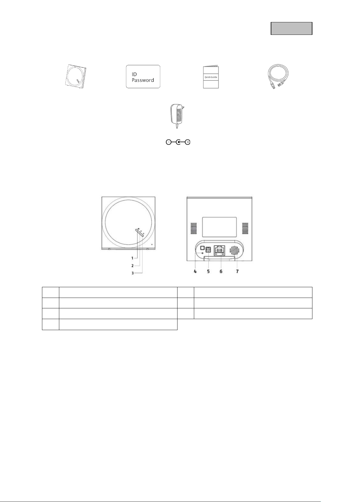
1. Scope of delivery
Gateway ID / Password Card Quick guide Network cables
Power supply 5V / 1.5A (DC plug: 3.5 x 1.35mm)
2. Description of the hardware
1 Z-Wave LED Indicator 2 Network LED Indicator
3 Status LED indicator 4 Reset button
5 Power supply (5V DC / 1A) 6 LAN interface
7 loudspeakers
6
Page 7
German
3. Description of the hardware functions
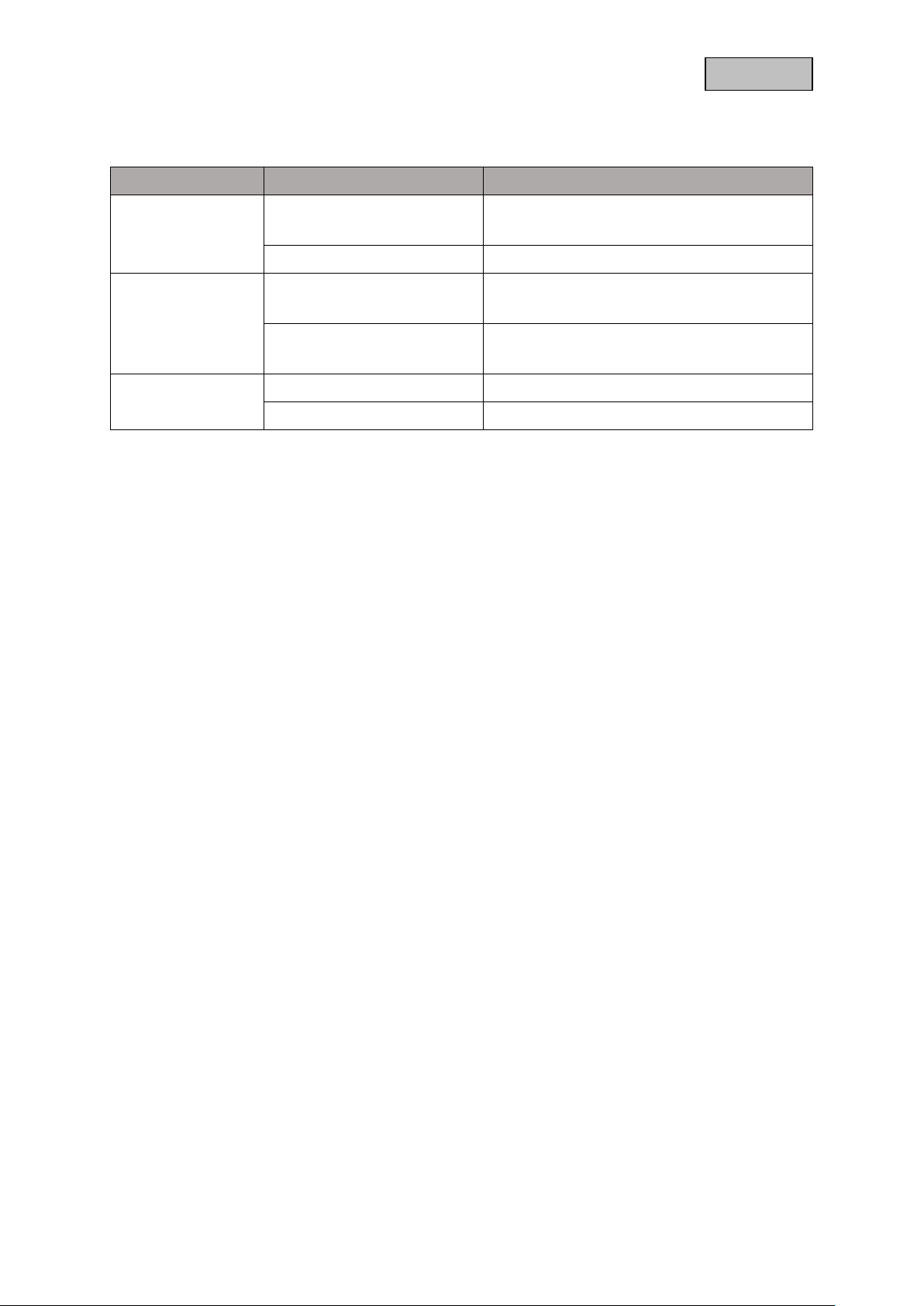
3.1. Status LEDs
LED state Description of the
Status LED
Off
Flashing red Gateway connected to power
Off
Network LED
Flashing Blue
Off Normal condition
Z-Wave LED
Flashing Yellow Gateway updates
Gateway not connected to power
Plug in the power supply unit
No network connection available
Connecting the network cable
Network connection available
Active data traffic
3.2. Factory settings / Reset
3.2.1. Soft reset (reset button)
During operation, press the reset butt on on t he b ack of the device for f ive s ec on ds. The gateway the n
restores the default admin access and the default network configuration (DHCP).
3.2.2. Configuration Reset (App)
To completely remove your Z-Wave Gateway configuration, c onnect to th e device us ing the ABU S ZWave One App. Open the configuration and select the optio n "Z-Wave f actory settings" in the admin
area.
If this controller is the primary controller for your network, the reset will cause the nodes in your network
to be orphaned, and it will be necess ary to exclud e and re-include all nodes o n the networ k after the
reset. If this contro ller is used as a secondary contro ller on the net work, use this procedure to res et
this controller only if the primary controller of the network is missing or otherwise not functional.
3.3. Loudspeakers
With the help of the integrated loudspeaker, preset warning tones or your own voice recordings can be
addressed and output using scenes or hotkeys.
You can select the function in the "THEN" part of the scene c onfiguration (6.8.4. Special cases and
special functions).
7
Page 8
German
4. Installation
To set up the gateway for the first time, c onnect the included network cable to your router and the
gateway and power the gateway with the included power supply.
5. ABUS Z-Wave One: First Access
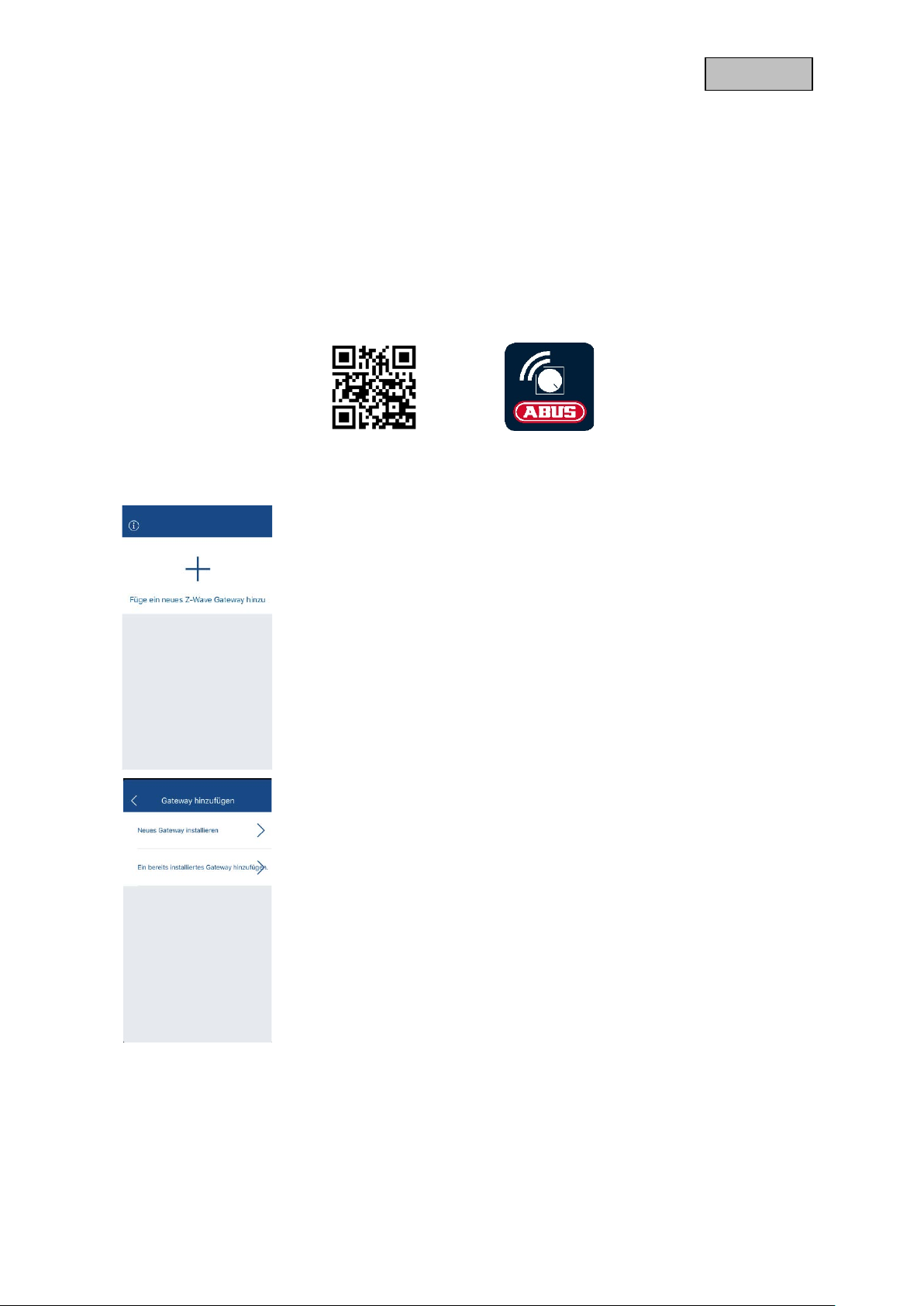
5.1. Downl oa d App
For the first access download the app "ABUS Z-Wave One" from the Google Playstore or Apple
Appstore.
5.2. Add Gateway
Open the app, click on the "+" sign to add a gateway.
Now select whether you want to add a new gateway or an already installed
gateway.
8
Page 9
German
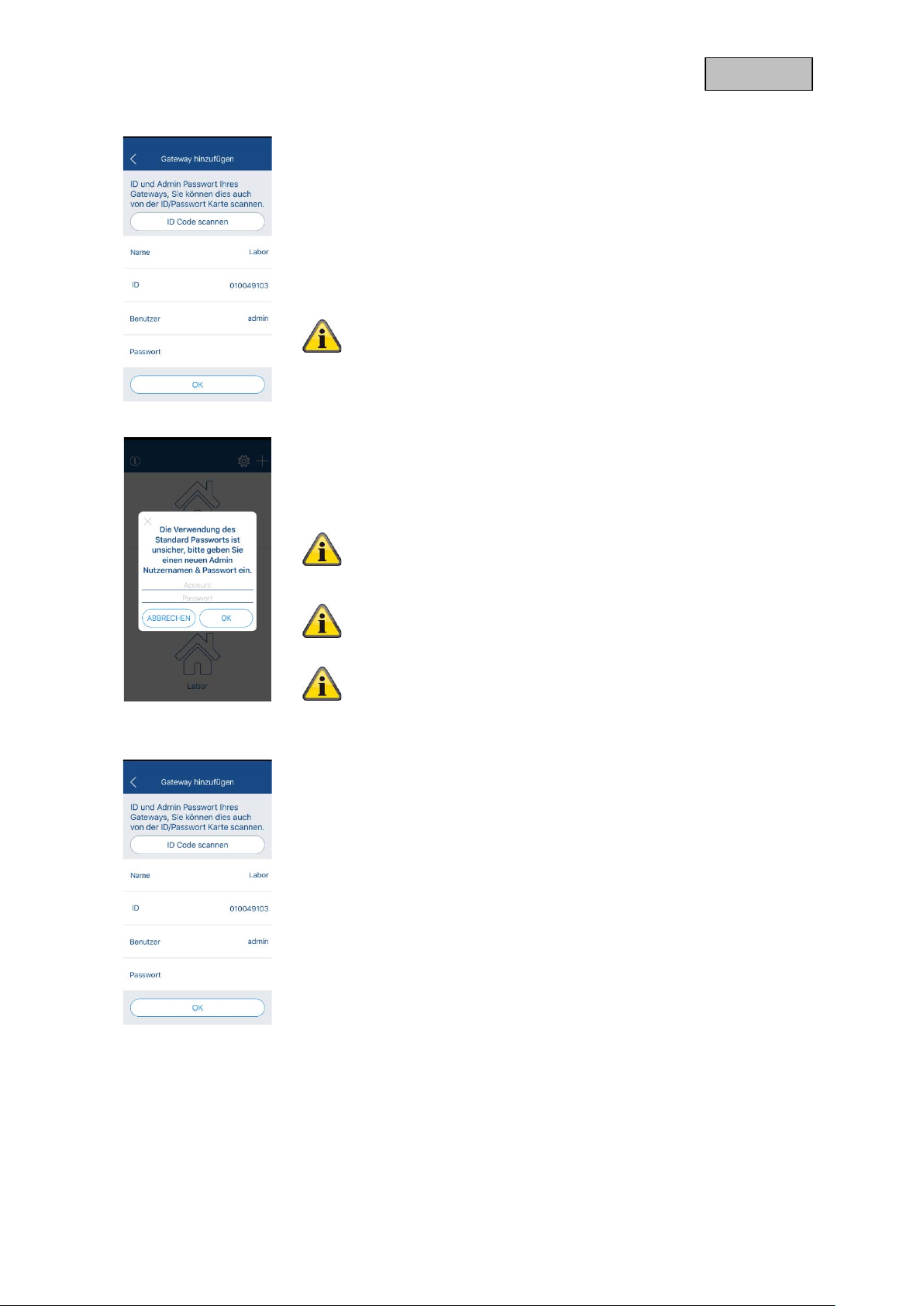
5.2.1. Add new gateway
Now assign a name to the gateway and enter the ID, user and password.
The ID, User and Password can be filled by scanning the enclosed
Password ID.
Click OK to confirm.
The initial default password for the admin user is empty.
Therefore do not enter a password.
User: admin
Password:
When you connect to the gateway for the first time, you must assign a new
user and password. A connection with the standard data is not possible for
security reasons.
5.2.2. Add an existing gateway
Assign a name to the existing gateway and enter the ID and your user data.
Click OK to confirm.
The password for the admin account must be provided with at
least 6 characters with 2 of 4 character types (upper case
letters / lower case letters / numbers / special characters).
For security reasons, user data can only be changed in the local
network of the gateway, so you can only complete the initial
setup if your smartphone/t ablet is on the same network as the
gateway.
If you have forgotten your access data, you can restore the
default user and password by soft reset.
5.3. Compatibility
The ABUS Z-Wave One App is compatible with the following devices:
• SHGW10000
9
Page 10
German
6. ABUS Z-Wave One App
6.1. Icon language
The device icons show you a certain status in the following colour variants:
• Dark Blue
o Information (e.g. temperature value)
o "Deactive state" (e.g. radio socket outlet off)
• light blue
o "Active state" (e.g. radio socket on)
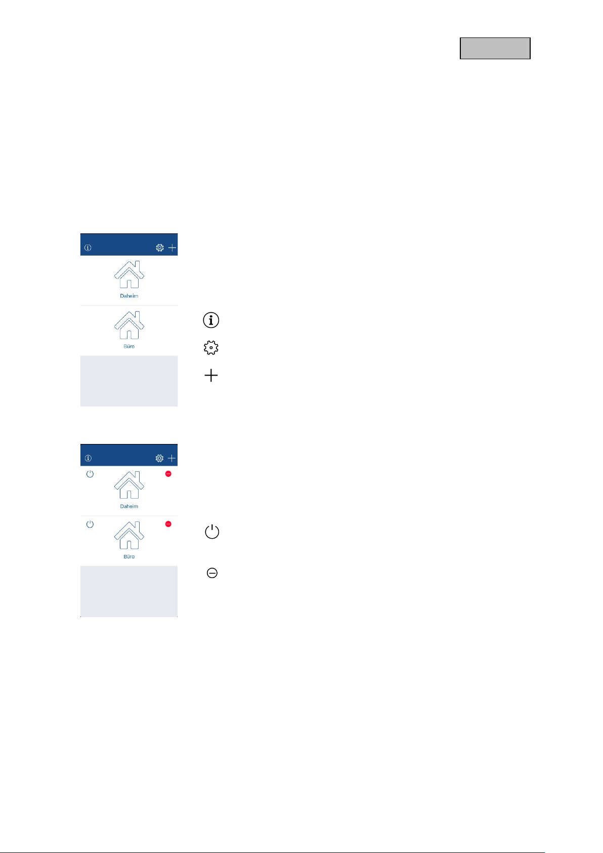
6.2. Home page
After successf ully adding your gateway(s), you will fin d them on the home
page. You can connect to the gateway by clicking on it.
You can execute the following additional functions in the overview:
Open the info page
6.2.1. Further settings
If you have activated the other settings, you can perform the following
functions:
Activate / deactivate further settings
Add device
Logging off from the gateway
At the next connection, you must enter the user data again. Do
this for other users for whom you have created your own user
account.
Remove device
10
Page 11
German
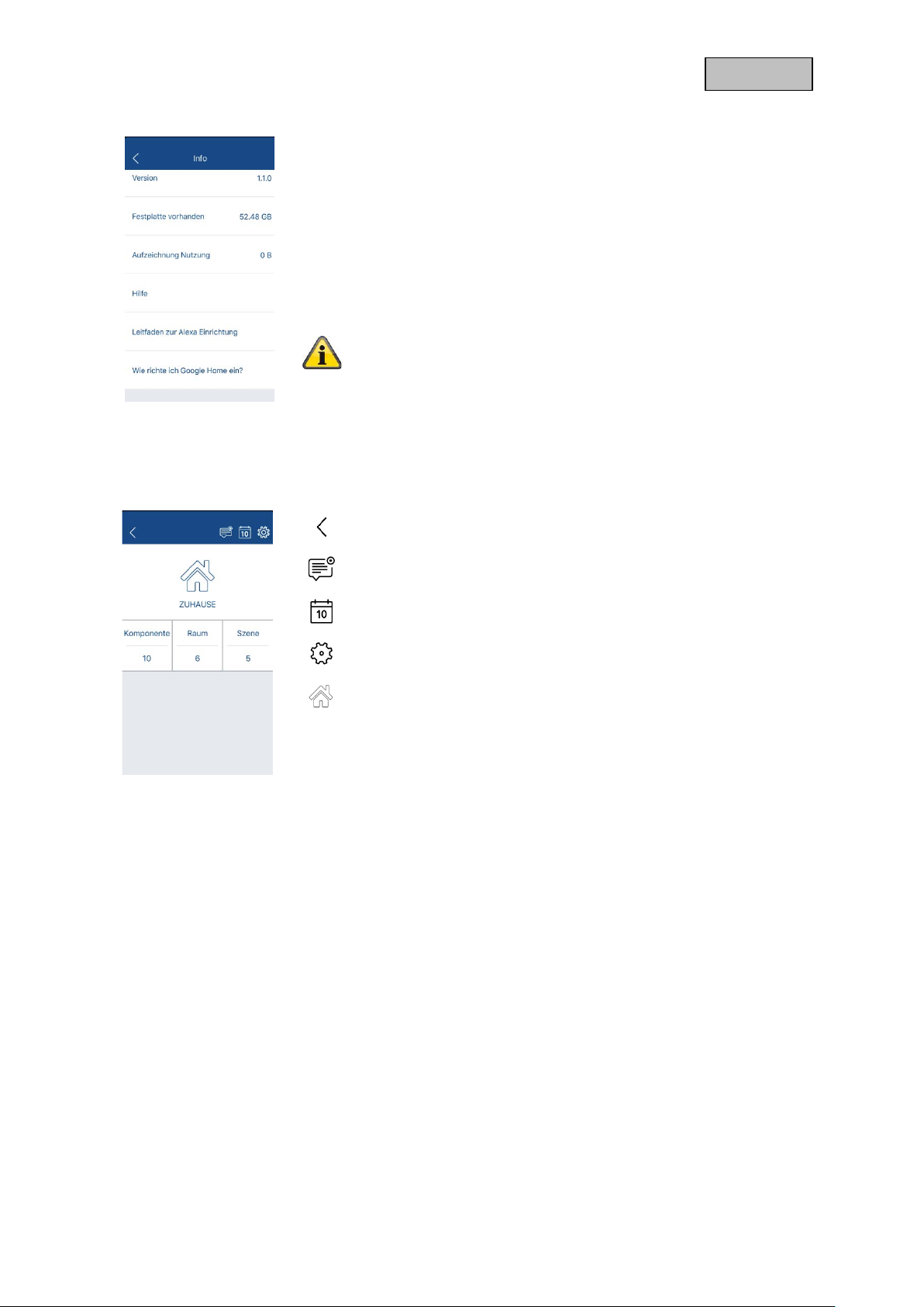
6.2.2. Info page
6.3. Overview
Here you will find the following information:
• Version number of the app
• Storage capacities (not relevant for the gateway)
• Illustrated instructions for the app
• Help for Alexa Voice Command
• Help for Google Home Voice Command
The Google Home voice control skill is currently in certification
and is expected to be officially available by the end of March.
After you have connected to your gateway, you can perform the following
actions:
Back to last page
Enable / disable all push notifications
Open event list
Open device settings (6.10. Device settings)
Open status/hotkey page (6.9. Status / Hotkey page)
device Open device list
space Open room list
scene Open scene list
6.3.1. Push notification
In the overview, the push notifications of the gateway can generally be activated or deactivated. For the
notification of specific events for devices or scenes, the notification for the event must also be activated
on the devices page or in the scene list.
11
Page 12

German
6.3.2. Event list
6.4. Device list
In the event list you have access to the last 1000 events of the gateway.
You can perform the following actions:
Limit events by keywords
Activate / deactivate event types
The device list gives you an overview of all taught-in devices.
Actuator devices (e.g. radio sockets) can be controlled directly by clicking
on the icon.
You can change the order of the devices in the list us ing Drag & Drop
(press and hold a line and move and release at the desired position).
You can perform the following additional actions:
Maximize Device List
Minimize device list
Add Device
Remove device
Open device page
12
Page 13

German
The following is displayed for each device:
• Device name
• Allocated space of the device
• Status of the device
Special symbols and their m eaning:
6.4.1. Add / Remove ABUS device
o Normal: Device has recently reported to the gateway.
o Sleep mode: Device is in sleep mode
o Inactive: device has not logged on to the gateway for
more than 24 hours
If the interview was not successfully completed when a device
was included, not all functionalities may be present and the left
symbol will be displayed.
You can either wait for the wake-up interval (usually every two
hours) until the next interview is started, or you can exclude the
device and re-pair it .
If a device is inactive, the "-" symbol is displayed. In this case,
check the battery or the functionality of the device.
After clicking on the "+" symbol, select the device you want to add or
remove under "ABUS" and follow the instructions in the app.
If the setup fails, you will be shown potential error sources in the app.
13
Page 14

German
All ABUS devices (except LEDs) have the new S2 safety standard. For
some devices (e.g. multisensor) you must select a selection of the S2
method:
• Enter DSK code
o Enter the first five digits of the DSK code manually.
The first five digits are located on the unit and/or on the
DSK card supplied.
• Scan DSK code
o Scan the QR code here.
The QR code is located on the device or on the enclosed
DSK card.
• No DSK/PIN code
o Start the setup without the DSK code.
If a DSK code is enclosed with the component, the component
should be added by using the "Enter DSK Code" or "Scan DSK
Code" method. The method "No DSK/PIN code" may fail
partially for such components..
If the adding via S2 is not succesfully, try to add the device via
S0 standard. For this, choose “other z-wave device” and
negate the S2 standard.
General information on the S2 safety standard:
The new S2 security standard closes a vulnerability that
allowed a potential attack at the time the device was first
paired.
You can find more information under:
wavealliance.org/mandatory-security-implementation-z-wavecertified-iot-devices-takes-effect-today/
6.4.2. Add / Remove ABUS Smartvest
After you have clicked on "+", select the "Smartvest" under "ABUS".
To add:
• Search your Smartvest either automatically in the network or enter
the DID of the Smartvest manually.
• Enter the security code of your Smartvest.
All available devices and the Smartvest itself are now displayed in the
device list. A detailed description of which functionalities are possible can
be found below. (8. Smartvest compatibility)
https://z-
14
Page 15

German
6.4.3. Add / remove device via Smart-Start
Add
Before you supply power tot he device, choose Smart-Start after you
pressed „+“.
The device musst support Smart-Start!
Delete
To delete a device from the Smart-Start List, click on the „-„ symbol and
choose „Smart-Start“.
Add
Click on add to scan the DSK-Code of the device. The code is normally
placed directly on the product or on a separate enclosed DSK-Code card.
Give the device a name and complete the process.
The device will be now listed in the Smart-Start list, if the process was
successful. You can add more devices to the Smart-Start list before you
start the inclusion / exclusion of the devices.
To start the inclusion- / adding process, supply the device with power. The
device will be added automatically.
Removing
To remove a device from the Smart Start list, click an existing entry and
confirm the removal.
Only i nclude one device at a time and wait until the device has
been successfully added before adding another device via
Smart-Start.
15
Page 16

German
6.4.4. Add / Remove device from other manufacturers
After clicking "+", select "Other Z-Wave Device" to add or remove thirdparty devices.
You can also add or remove ABUS devices with this selection.
The preselection of the S2 standard and the illustration for
triggering the device are missing here.
Then select whether the third-party device supports the S2 security
standard or not. This information can be found in the manufacturer
specifications of the third-party device.
For S0 devices follow the instructions in the app to add the device.
If the setup fails, you will be shown potential error sources in the app.
For more details about adding devices via S2 method, please refer to the
section in the “Add / remove ABUS device”.
Reference
According to the Z-W ave certif ication a n integrati on of an y devices is possible. H owever, it
can happen that som e functionalities of the third-party device are not correctly supported.
ABUS only guarante es the complete f unct ional ity of A BUS devices. If a m alf unction sho uld
occur, contact our customer service with the manufacturer and model number of the device.
We will consider this for a next release version.
16
Page 17

German
6.5. Device page
On the device page, all essential status displays of the device are
displayed.
Actuators of the devices (e.g. radio socket) can be controlled dir ectly by
clicking on the icon.
You can also perform the following actions:
Name Change device name
Force Delete Remove defective or inactive devices
Displays the connection quality. If the
component is connected via a mesh node, the
connection quality to the last mesh node is
Signal strength
displayed.
Click on the line to open the detail view.
Wake-up interval Change wake-up interval
Room assigned Change assigned room
6.5.1. Signal Strength Detail View
In the detail view you can see the connection quality as -dBm value, like
the last message of the component. If the component is connected to your
gateway by several mesh nodes, these are also displayed.
Open configuration page
Activate/deactivate push notification for the
respective status
For a connection via mesh nodes, only the connection qua lity
to the last mesh node can be displayed. In this case, a poor
connection quality from component to mesh node may be
present despite good connection quality displayed to the mesh
node.
17
Page 18

German
6.5.2. Wake-up interval
The wake-up interval determines how often a battery device wakes up and
reports to the gateway.
A change in the wake-up interval will significantly affect the
battery life of the device. The stated battery life of ABUS
devices refers only to the standard wake-up interval! You can
find this information in the BDA of the device.
The wake-up interval does not determine the transmission
interval of the sensor reports (e.g. temperature, humidity,
current measurement, etc.). These must be set separately in
the configurations.
6.5.3. Configuration Page - ABUS devices
With ABUS devices that allow the configuration of certain parameters, the
individual parameters can be adjusted with sliders. Further assistance is
available for individual parameters by clicking on the question mark.
For components with direct power supply (e.g. radio socket), all
current parameter settings are queried. This can lead to a
longer loading time of the configuration page.
For components with battery power supply, the configuration
page with the standard values is called up. Changes are stored
directly in the gateway to the next view and are synchronized
the next time the component wakes up.
You can still set each individual parameter using Manual Configuration.
6.5.4. Configuration Page – Manual configuration
Some devices allow the configuration of certain parameters. These can be
set from the configuration page.
Refer to the manual of the respective component to find out which
parameter settings are possible.
Obtain value:
Enter the parameter, select the corresponding byte size (1 / 2 / 4 bytes)
and click on "GET".
Set value:
Enter the parameter and the value, select the byte size (1 / 2 / 4 bytes)
and click on "SET".
18
Page 19

German
s that are
6.6. Room / Group list
reference
Groups have a similar str ucture to rooms, which is why the y are not described in more
detail.
Groups are used to group actuators together across rooms in order to integrate them into
scenes.
(e.g. "Light" group for switching on / off all lights in the house)
In the room list, you have an overview of all created rooms.
You can change the order of the rooms or groups in the list using Drag &
Drop (press and hold a line and move and release at the desired position).
You can perform the following actions:
Maximize room list
Minimize room list
The following is displayed for each room:
°C Temperature display
%
LUX Brightness display
Reference
The room "unassigned" is a fixed, non-erasable room. New devices, device
removed from a cr eate room and devices that were in a rem ove room ar e all moved to th e
"unassigned" room.
Add room
Remove room
Open room side
Switch, light or socket active / deactivated
RGBW LEDs active / deactivated
Humidity disp lay
19
Page 20

German
o
The respective displays can also be actively controlled from the room list
by a click.
Activate / deactivate all switches, lights or sockets
Enable / disable all RGBW LEDs
°C Open temperature progression
Open the moisture progression
%
LUX Open brightness progression
In the temperature / humidity and brightness progression, you can choose
between the individual values under "Details" by clicking on them.
You can switch between the day and month view using the Day / Month
button.
6.6.1. Add / remove room
The value of the brightness is always displayed in percent,
because different components output a brightness in e.g.
percent or LUX.
The conversion from LUX to percent is done as follows:
• More than 1300 Lux
o 100 %
• More than 150 Lux
o (93 + [Lux * {2600 - Lux} / 260000] ) %
• Less than 150 Lux
(20 + [Lux * {423 – Lux} / 550] ) %
After you have clicked on the "+" symbol, give the room a name.
20
Page 21

German
6.7. Room page
,
All existing devices are displayed on the room page.
Actuators of the devices (e.g. radio socket) can be controlled directly by
clicking on the icon.
You can perform the following actions:
Name Change the name of the room
6.7.1. Heating schedule
Temperature
Device
Humidity Device
Lux Device
Select the device whose value is to be used in
the room list and in the temperature progression.
Select the device whose value is to be used in
the room list and in the humidity progression.
Select the device whose value is to be used in
the room list and in the brightness progression.
Open temperature / humidity and brightness
progression
Configure heating plan
(If heating controller available)
Add / move / remove devices
Open device page
If you have added a heating controller to the room, you can access the
heating plan.
Here you can set whether the heater is controlled by the gateway status
or by a manual schedule.
Gateway status control:
Set the temperature values for the three different gateway states.
Manual schedule control:
Set the time windows and temperature for each day.
21
Page 22

German
6.8. Scene list
In the scene list you have an overview of all created scenes.
You can change the order of the scenes in the list using Drag & Drop
(press and hold a line and move and release at the desired position).
You can perform the following actions:
Maximize scene list
Minimize scene list
Add scene
Remove scene
Activate / deactivate scene
Trigger scene
6.8.1. Add / Remove scene
After you have clicked on the "+" symbol, give the scene a name.
The scene must then be adjusted.
Configure scene:
• Change the name of the scene
• Using dynamic icons (app icons)
• Using a fixed icon (personal camera image)
Activate/deactivate push notification when scene is
triggered
22
Page 23

German
e (after checkbox is checked) to switch between
6.8.2. Setting the scene
The scene is divided into three conditions:
WHAT IF
Condition of a device required to trigger the scene.
(e.g. opening detector is "open")
Up to 6 conditions can be linked with "AND" or "OR" connections.
• "AND": e.g. 6 of 6 conditions must be fulfilled
• "OR": e.g. 1 of 6 conditions must be fulfilled
THEN
Actions that are to be switched through this scene.
(e.g. switch radio socket "on")
Up to 12 actions can be switched in a scene.
For each action, a n action durati on can be def ined. The value "seconds"
can be clicked her
seconds, minutes or hours.
WHEN
Scenes can be associate d with the addit ional condit ion of gate way status
"Home", "Away" and "Sleep".
(e.g. IF opening det ector "open" / THEN s witch radio socket "on" / I F at
status "at home")
Alternatively, you can link the scene to a time. Here you have the following
choice:
• Always
• Specific time period each day
• Specific time period on specific days each week
• Specific time period on specific days
A scene can also be saved without a WHEN condition. The time
value "Always" is automatically set for the scene.
If a condition has been defined incorrectly, click the condition to adjust it.
(e.g. temperature value incorrectly selected)
If an incorrect condition has been selected, press and hold the condition
to remove it.
Once a WHEN condition has been selected, it can no longer be
removed, but only modified by holding it down for a long time.
23
Page 24

German
6.8.3. Examples
IF: temperature in the hallway or cellar is below 23° C
THEN: Switch heating controller to 24° degree
WHEN: Every day from 08:34 - 16:39
IF: opening detector is "open
THEN: Turn the siren on.
WHEN: When gateway status is “Away”
IF: Water detector triggers
THEN: switch siren "on" and switch RGBW-LED on with color blue
WHEN: Always
24
Page 25

German
"Every week" / "Fixed time" must be
6.8.4. Special cases and special functions
A scene can also be set without an IF condition.
For example, actions can be defined for the status of the
gateway.
(e.g. switch socket "off", with status "on the way")
Actions can also be linked to the time settings. Here,
however, only the start time at which the actions are
executed is relevant. So at the end time the actions are not
undone.
(e.g. switch the socket "off", every day at 10 o'clock)
In the THEN part of a scene, the following additional functions
can be set for actuators:
Action duration
The action duration specifies how long the actuator should
hold the selected action af ter the scene has been triggere d.
(e.g. switch socket "on" for 10 seconds)
You can set the ac tion d uration in seconds / minut es / ho urs.
To do this, click on the text "Seconds / Minutes / Hours".
Reverse action to end time
This option is only available in timed scenes. In the W HEN
part, "Every day" /
selected accordingly.
If this option is active, the action is exec uted at the s tart time
and is reversed at the end time.
(e.g. switch socket "on" at 07:45 and switch socket "off" at
11:15).
25
Page 26

German
In the THEN part you can select the loudspeaker of the
gateway as an action.
If you click on the loudspeaker in the THEN part after
selecting it, you have the following setting options:
• Setting the repetition of the sound
• Setting the tone
• Record and play your o wn voice message
In the THEN part you can install a sequencer for the actions.
The sequencer makes it possible to switch all actuators one
after the other in a certain interval and executes the actions
several times one after the other or in an endless loop,
depending on the settings.
26
Page 27

German
6.9. Status / Hotkey page
On the hotkey and status page, you can change the status of the gateway
by clicking on it.
In addition, you can perform the following actions for hotkeys:
Configuring Hotkeys
If you have created hotkeys, you can trigger them with a single click.
You can change the order of the hotkeys in the list using Drag & Drop
(press and hold a line and move and release at the desired position).
When you configure the hotke ys, you can perform the following actions:
6.9.1. Add / remove hotkey
Hot
key
Add Hotkey
Remove Hotkey
By clicking on the hotkey, you can trigger the hotkey.
Rename Hotkey
After you have clicked on the "+" symbol, give the hotkey a name.
The hotkey must then be set.
27
Page 28

German
6.9.2. Setting the Hotkey
A hotkey behaves like the THEN part of a scene and can thus be set.
A hotkey can only be triggered manually by clicking on the hotkey or via
voice control.
28
Page 29

German
6.10. Device settings
Here you will find a list of all available settings:
Name: Change the name of the gateway
ID: Displays the ID of the gateway.
Information:
• Model Index
• Firmware version
• Registration
• Network type
o Indication whether DHCP or Fixed IP is set
• IP address
Network:
• Choice between DHCP or Fixed IP
o If you select a fixed IP, assign a free IP address in your network to the gateway. In
conventional networks, the subnet mask is always "255.255.255.0". Enter the IP
address of your router under "Default Gateway", "DNS 1" and "DNS 2".
If you have made an err or when assigning a fixed IP a nd c ann ot f ind t he g at e wa y aga in,
you can restore the default value "DHCP" by soft reset.
Admin:
• Log in
o Change the login information of the admin user here.
This is only possible in the local network of the gateway.
• Z-Wave factory settings
o Removes all devices, rooms and scenes from the gateway
Esteem
The devices still ha ve the h ome ID of the gate way stor ed and m ust be rese t bef ore the y
can be taught again. Alternatively, you can carry out the "Remove" process with the device
in the app before teaching in the device.
• Z-Wave Backup / Restore
o Here you can save a local backup of the gateway on your smartphone and reinstall it
if necessary.
• Refresh:
o In exceptional cases, our technical support may ask you to manually install a new
firmware. This function is required for this.
29
Page 30

German
6.10.1. User management
In user management, you can create additional users in addition to the
admin user. These can be limited with different authorizations in the
operation with the gateway.
Enter the following data when creating a user:
• Username (required for login)
• Password (required for login)
• Permissions
o Hotkey (change status and switch hotkeys)
o Operation (access to status/hotkey, devices, rooms and
scenes, but no setting possible)
o Settings (access to status/hotkey, devices, rooms and
scenes, setting possible)
• User code
• Controllable devices
• Allowed time
Access to the device setti ngs (except networ k) is not possible
for any additional user.
Please note that for the authorization "Operation" and "Settings"
the password has at least 6 c haracters with 2 of 4 character
types (upper case letters / lower case letters / numbers / special
characters), otherwise the access for the user is not possible.
o Define the user code that enables the user to perform an
action when entering an access device or an external
control panel.
o Specify whether access devices can be controlled by the
user
o Specify a time period during which the user has access
and can perform actions.
30
Page 31

German
7. Firmware update
If a new firmware is available for your gateway, you will be notified after the connection with the gateway
and have the possibility to update directly. All settings are retained.
Updating the gate wa y takes about 3-5 minutes. Do no t d is connec t the gateway from the
power supply during this time!
More information about the changes can be found under the download tab on the product website:
www.abus.com/product/SHGW10000
8. Smartvest Compatibility
The ABUS Z-Wave Gateway is also compatible with the ABUS Smartvest wireless alarm system.
8.1.1. Connection between Z-Wave Gateway and Smartvest
You can integrate the Smart vest wireles s alarm system into the gatew ay locall y (also with out Intern et
access) or via the cloud. Thus the Smartvest and the Gateway can also be located in different networks
/ buildings. If the Smartvest is in another network, the DID must be entered manually when the
Smartvest is added.
8.1.2. Synchronized data
After a Smartvest has be en as sign ed to the G atewa y (as desc ribed above), th e followin g data can be
synchronized between the Gate wa y and the Sm ar tvest
• Smartvest
o Status (Active / Internal Active / Deactive)
o Status Alarm (Alarm / Panic Alarm / 24H Alarm / Sabotage Alarm)
o Temperature
o Air humidity
• Smartvest magnetic contact
o device name
o Status (Open / Closed)
o sabotage contact
• Smartvest motion detector
o device name
o Status (Movement / No movement)
o sabotage contact
• Smartvest vibration detecto r
o device name
o Status (Vibration / No vibration)
o sabotage contact
31
Page 32

German
• Smartvest Water Detector
o device name
o Status (Water / No water)
If the Smartvest water detector has been triggered, the status is only reset by deactivating
the Smartvest.
• Smartvest smoke/heat detec tor
o device name
o Status (Fire / No fire)
If the Smartvest smoke/heat detector has been triggered, the status is only reset by
deactivating the Smartvest.
• Smartvest wireless pushbutton
o device name
o Action (value 1: short press / value 2: long press)
In the IF section, t he Smartvest radio pushbutton can be used with the value 1 (short
press) or value 2 (long press).
• Smartvest Door Gong
o device name
o Action (selection of the 4 gong tones)
• Smartvest radio socket outlet
o device name
o Action (On / Off)
32
Page 33

German
name in the
8.1.3. Smartvest device side
On the Smartvest device page in the Z-Wave One app, you can perform
the following additional functions:
• Synchronize status with Smartvest
• Update Smartvest devices
o If activated, the gateway status is adapted to the status of
the Smartvest.
Smartvest Active -> Gateway switches to Away
Smartvest Internal Active -> Gateway switches to Sleep
Smartvest Deactive -> Gateway switches to Home
o If you have added new devices in the Smartvest or
deleted Smartvest devices in the Z-Wave One app, you
can restart the device synchronization by clicking on the
button again.
It is possible to change the names of the Smartvest devices
afterwards. However, if you restart the synchronization, the
names will again be adapted to the device
Smartvest.
8.1.4. Smartvest in the scene
You can link the status of the Smartvest to actions as a condition in the IF
part.
You can link the status of the Smartvest as an action in the THEN part.
The scene is only triggered when the Smartvest status changes.
If an action (e.g. r adio socket o n) is reset manuall y, the scene
is only triggered when the Deaktiv button is pressed again.
To prevent foreign com ponents from interf ering with the alarm
logic of the Sm artvest alarm system, changi ng the Smartvest
status in scene control is only possible if all conditions in the IF
part are related to ABUS Z-Wave components.
If a third-party component is selected, it is no longer possible to
change the status in the THEN part. An already selected status
change is automatically removed.
33
Page 34

German
You can link a Smartvest alarm to actions as a condition in the What-If
part. You can select the following alarm types:
• Alarm (triggering of a Smartvest device in active state)
• Panic alarm (manual triggering of an alarm by e.g. the Smartvest
remote control)
• 24H alarm (triggered by a 24H device, such as the water detector)
• Sabotage alarm (triggering sabotage of a Smartvest device)
You can send a panic alarm to Smartvest as an action in the THEN-part.
9. Technical data
SHGW10000
Number of devices 120
Number of rooms / groups 40
Number of scenes 60
Wireless modulation Z-Wave Plus / FSK (BFSK / GFSK)
S2 safety standard Yes
Radio frequency 868.42 MHz
Transmitting power 2 dBm
Radio range (depending on installation) 20 - 100m
Software App: ABU S Z -Wave One (Android / iOS)
Dimensions (mm) (W x L x H) 96 x 21 x 96
Material Plastic
Power supply 5V DC
Current consumption 280mA
Network connection RJ45 socket (10 / 100Mbits)
Loudspeakers Yes
Operating temperature 0° - 50° Celsius
34
 Loading...