

Page 1
Schlüsselschalter
INSTALLATIONSANLEITUNG
Key switch
Installation Guide ........................................................... 5
Interrupteur à clé amovible
Instructions d’installation ................................................. 9
Interruttore a chiave
Istruzioni per l’installazione ............................................13
Sleutelschakelaar
Installatieaanwijzingen................................................... 17
Nøglekontakt
Installationsvejledning ...................................................21
SE1000
SE1100
1
Page 2

Vorwort
Sehr geehrte Kundin, sehr geehrter Kunde,
wir bedanken uns für den Kauf dieses Aufputz-, bzw. UnterputzSchlüsselschalters. Mit diesem Gerät haben Sie ein Produkt erworben, das nach
dem heutigen Stand der Technik gebaut wurde. Dieses Produkt erfüllt die
Anforderungen der geltenden europäischen und nationalen Richtlinien. Die
Konformität wurde nachgewiesen, die entsprechenden Erklärungen und
Unterlagen sind beim Hersteller hinterlegt. Um diesen Zustand zu erhalten und
einen gefahrlosen Betrieb sicherzustellen, müssen Sie als Anwender diese
Montageanleitung beachten!
Hinweise
Der Schlüsselschalter dient im Zusammenhang mit einer Einbruchmelde- oder
Überfallmeldeanlage zum Scharf-, bzw. Unscharfschalten der Anlage oder ihrer
Teilbereiche.
Er kann darüber hinaus auch eingesetzt werden zur Steuerung von anderen
elektronischen Geräten, wie Maschinen, Garagentoren, o.ä..
Der Schlüsselschalter arbeitet dabei je nach Einstellung als Impuls- oder
Dauerkontaktgeber. Durch den Deckel- und Wandabrisskontakt (nur bei der
Aufbauvariante), sowie der Kernziehschutzrosette und dem hochwertigen
Zylinder aus dem Hause ABUS ist der Schlüsselschalter in erhöhtem Masse
gegen Angriffe von Außen geschützt.
Hauptmerkmale
x Aufputz-, bzw. Unterputz-Schlüsselschalter
x Stabiles wetterfestes Gehäuse
x Kernziehschutzrosette
x Deckel- und Wandabrisskontakt (nur bei Aufbauvariante)
x Dauer- oder Impulskontakt
x Farbige LED Anzeigen (rot/gelb)
x Modernes gefälliges Design
Lieferumfang
4 Gehäusespezialschrauben inkl. Stiftschlüssel
1 Runddichtung schwarz (nur SE1000)
1 Flachdichtung weiß (nur SE1100)
4 Mauerdübel 6mm inkl. Schrauben 4,5 x 35mm
2
Page 3
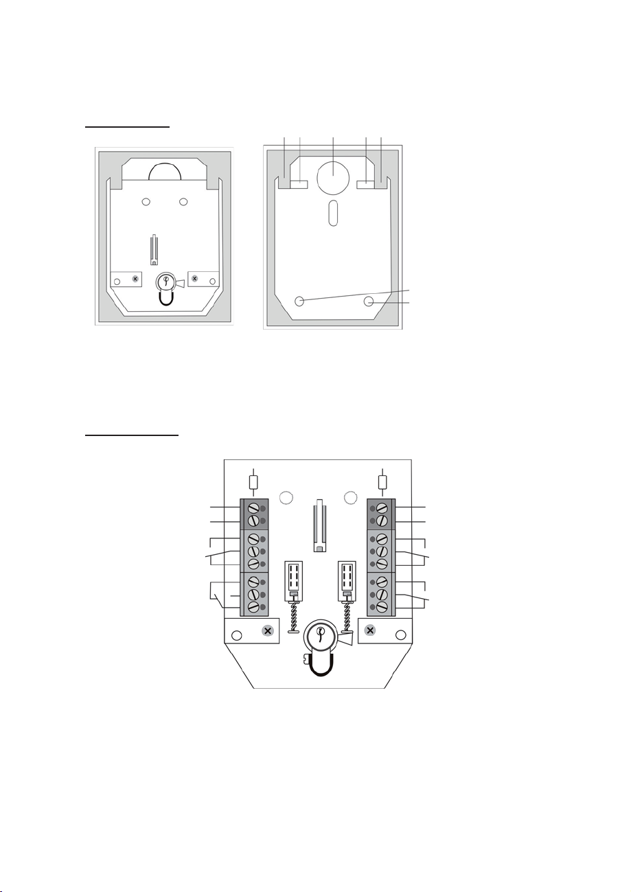
Beschreibung
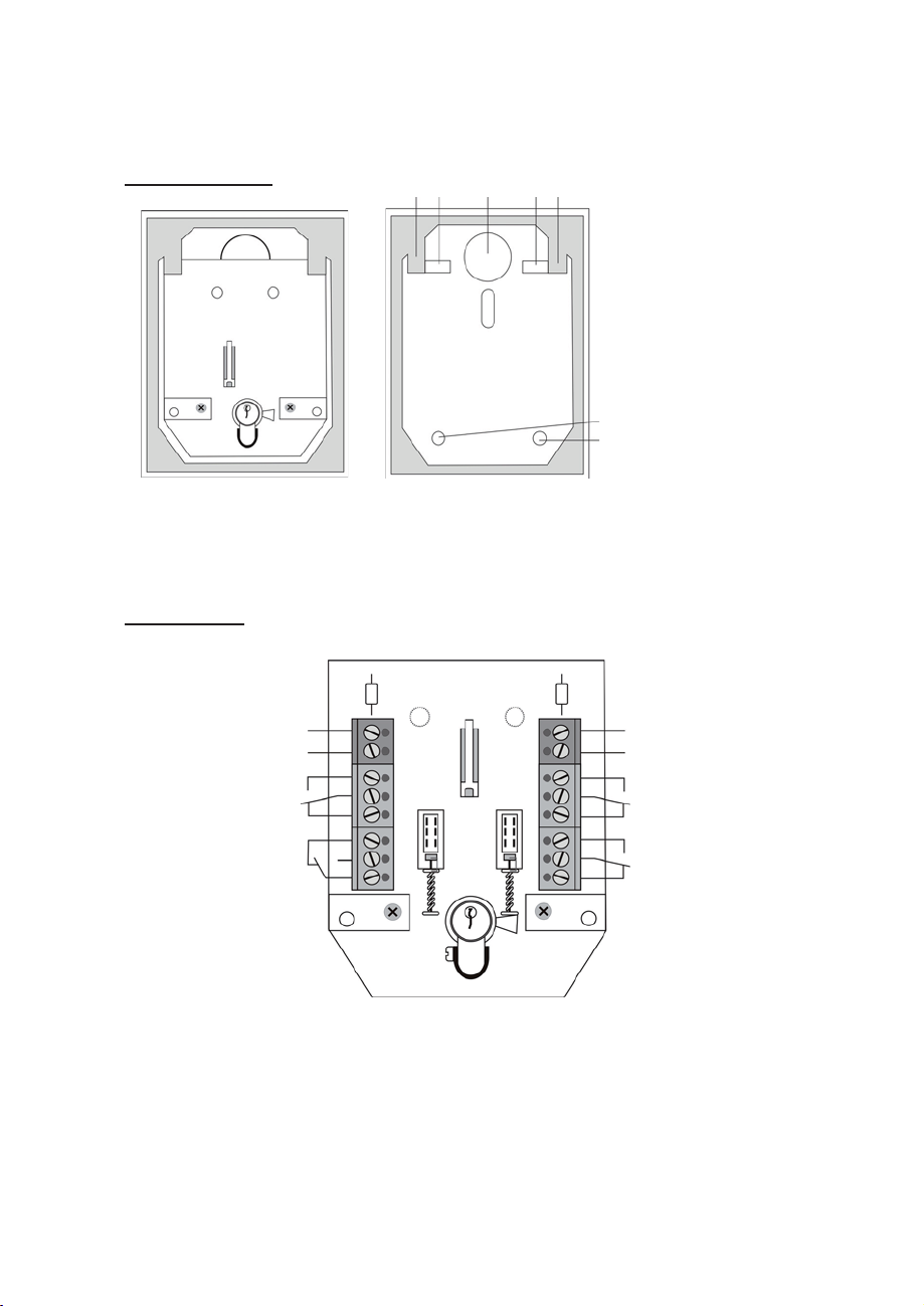
Abb.1 Gehäuse offen
(mit Platine)
Anschlüsse
1 2 2 3 1
1 Platinenhalter
2 Wandbefestigung
3 Kabeleinführung
2
2
Abb.2 Gehäuse ohne Platine
12V Spannung für LED
Masse für LED (rot
NO
COM
NC
NC
NO
COM
Schalter S1
Sabotage-
kontakte
)
S2 S1
12V Spannung für LED
Masse für LED (gelb)
NO
COM
NC
NO
COM
NC
Schalter S2
Anmerkung:
Die beschriebene Schalterstellung gilt für den Fall, dass der Gehäusedeckel
geöffnet ist.
3
Page 4
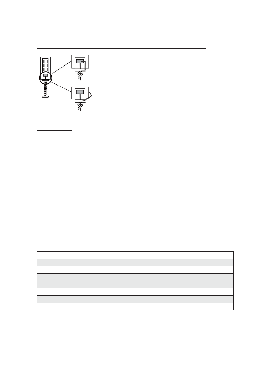
Ändern des Schaltverhaltens (Impuls-/Dauerkontakt)
1. Im Auslieferungszustand ist der
Schlüsselschalter als Dauerkontaktgeber
Dauer
Impuls
eingestellt. Zum Ändern gehen Sie wie
folgt vor:
2. Entfernen Sie den oberen Teil der Klemme an
den Tastern und legen Sie ihn seitlich ab.
3. Der Schlüsselschalter arbeitet nun als
Impulsgeber.
Installation
1. Öffnen Sie mit dem beiliegenden Stiftschlüssel die Deckelschrauben und
nehmen Sie den Gehäusedeckel ab.
2. Enterfernen Sie die beiden Platinenschrauben links und rechts vom
Zylinder.
3. Ziehen Sie die Platine am Zylinder vorsichtig nach oben heraus.
4. Benutzen Sie die Rückseiten des Schlüsselschaltergehäuses zum Markieren
der Befestigungen (2). Bohren Sie dann die Haltelöcher.
5. Führen Sie das Anschlusskabel durch die vorgesehene Öffnung.
6. Befestigen Sie die Rückwand an, bzw. in der Wand.
7. Stellen Sie die Verbindungen an der Klemmleiste (8) wie beschrieben her.
8. Setzen Sie die Platine wieder ein, setzen Sie den Gehäusedeckel (1) wieder
auf und ziehen Sie die Deckelschrauben fest. Achten Sie dabei darauf,
dass der Dichtungsring sauber in der Gehäuse-Nut liegt.
Technische Daten
Spannungsversorgung LED 10 – 15 VDC
Max. Stromaufnahme je LED 2mA
Kontaktbelastbarkeit 30V DC / 0,5A
Abmessungen Aufbau 85 x 114 x 42mm (BxHxT)
Abmessungen Einbau 106 x 134 x 42mm (BxHxT)
Schutzart IP55
Anzahl Kontakte 3 (Wechsler)
Gewicht 450g
Der Hersteller behält sich vor technische Änderungen ohne Vorankündigung
durchzuführen.
4
Page 5

Key switch
INSTALLATION GUIDE
Schlüsselschalter
Installationsanleitung....................................................... 1
Interrupteur à clé amovible
Instructions d’installation ................................................. 9
Interruttore a chiave
Istruzioni per l’installazione ............................................ 13
Sleutelschakelaar
Installatieaanwijzingen................................................... 17
Nøglekontakt
Installationsvejledning ...................................................21
SE1000
SE1100
5
Page 6

Preface
Dear Customer,
Thank you for purchasing this surface-fitted/flush-fitting key switch. You made
the right decision in choosing this state-of-the-art technology, which complies
with the current standards of domestic and European regulations. The CE has
been proven and all related certifications are available from the manufacturer
upon request. To maintain this status and to guarantee safe operation, it is your
obligation to observe these operating instructions.
Notes
The key switch is equipped with a burglary/tamper sensor and is used for
switching on or off the alarm system of an entire location or sections of the
location.
It can also be used for controlling other electronic equipment such as machines,
garage doors, etc.
The key switch functions as an impulse or permanent contact, depending on the
settings. The key switch is well protected against external interference, thanks to
the cover contact and the anti-removal wall contact (surface-fitted model only),
as well as the reinforced fascia plate, which prevents removal of the high-quality
ABUS cylinder.
Main features
x Surface-fitted or flush-fitting key switch
x Stable, weatherproof casing
x Reinforced fascia plate to prevent lock removal
x Cover contact and anti-removal wall contact (surface-fitted model only)
x Permanent or impulse contact
x Coloured LEDs (red/yellow)
x Modern, attractive design
Scope of delivery
4 special casing screws with key
1 circular seal black (SE1000 only)
1 sealing plate white (SE1100 only)
4 x 6mm wall plugs including 4.5 x 35mm screws
6
Page 7
Description
1 2 2 3 1
1 PCB holder
2 Wall fixing
3 Cable hole
Fig. 1 Casing open
(with PCB)
Connections
12V for LED
Ground for LED (red)
Switch S1
Tamper
contacts
NO
COM
NC
NC
NO
COM
Fig. 2 Casing without PCB
S2 S1
2
2
12V for LED
Ground for LED (yellow)
NO
COM
NC
NO
COM
NC
Switch S2
Note:
The switch position described applies when the cover is open.
7
Page 8
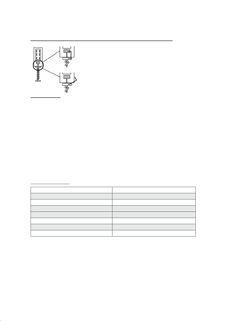
Changing switch mode (impulse/permanent contact)
1. The factory setting of the key switch is
permanent contact. To change the switch
Permanent
Impulse
mode:
2. Remove the upper part of the clamp and
swing it to the side.
3. The key switch is now set to impulse mode.
Installation
1. Using the key supplied, unscrew the cover screws and remove the cover
plate.
2. Remove the two PCB screws on the left and right of the cylinder.
3. Pull the cylinder and PCB carefully upwards and out.
4. Use the back of the key-switch case as a template for marking the drill
holes (2). Drill the holes for the fixing screws.
5. Pull the connector cable through the opening provided.
6. Fix the casing to or in the wall.
7. Connect the cables to the terminal block (8) as described.
8. Replace the PCB in the casing, replace the cover (1) and tighten the cover
screws. Make sure that the sealing ring sits firmly in the housing groove.
Technical data
Voltage supply LED 10–15 V DC
Max. power consumption per LED 2mA
Maximum contact capacity 30V DC / 0.5A
Dimensions (surface fitting) 85 x 114 x 42mm (WxHxD)
Dimensions (flush fitting) 106 x 134 x 42mm (WxHxD)
Protection type IP55
Number of contacts 3 (switchable)
Weight 450g
The manufacturer reserves the right to make technical modifications without
prior notice.
8
Page 9

Interrupteur à clé amovible
INSTRUCTIONS D’INSTALLATION
Schlüsselschalter
Installationsanleitung....................................................... 1
Key switch
Installation Guide ........................................................... 5
Interruttore a chiave
Istruzioni per l’installazione ............................................ 13
Sleutelschakelaar
Installatieaanwijzingen................................................... 17
Nøglekontakt
Installationsvejledning ...................................................21
SE1000
SE1100
9
Page 10

Préface
Chère cliente, cher client,
Nous vous remercions d’avoir porté votre choix sur cet interrupteur à clé
amovible destiné à un montage apparent ou encastré. Par l’achat de ce
produit, vous disposez maintenant d’un appareil faisant appel à une
technologie de pointe. Ce produit est conforme aux exigences des directives
européennes et nationales en vigueur. La conformité de ce produit a été
prouvée. Les déclarations et documents correspondants ont été déposés chez le
fabricant. Pour que cette conformité persiste et qu’un fonctionnement en toute
sécurité puisse être assuré, lire attentivement ces instructions de montage !
Remarques
L’interrupteur à clé amovible permet, conjointement à un système anti-intrusion
ou anti-agression, d’activer ou de désactiver le système ou les zones qu’il
comprend.
De plus, il peut également servir à commander d’autres appareils électroniques,
tels que des machines, des portes de garages ou autres.
Dans ce cadre, l’interrupteur à clé amovible fonctionne, en tant que contacteur
permanent ou impulsionnel, suivant le réglage réalisé. De par le contact du
couvercle et anti-arrachement mural (uniquement avec la variante apparente),
ainsi que la rosette de protection du cylindre et le cylindre de qualité de la
société ABUS, cet interrupteur à clé amovible dispose d’une protection forte
contre les agressions venant de l’extérieur.
Principales caractéristiques
x Interrupteur à clé amovible pour montage apparent ou encastré
x Boîtier stable résistant aux intempéries
x Rosette de protection du cylindre
x Contact de couvercle et anti-arrachement mural (uniquement dans le
cadre de la variante apparente)
x Contact permanent ou impulsionnel
x Affichage à DEL de couleur (rouge/jaune)
x Design modern agréable
Livraison
4 vis de boîtier spéciales et clé mâle coudée
1 joint rond noir (uniquement SE1000)
1 plaque d’étanchéité blanc (uniquement SE1100)
4 chevilles de fixation murale de 6 mm avec vis de 4,5 x 35 mm
10
Page 11

Description
2 1 2 3 1
1 Porte-platine
2 Fixation murale
3 Entrée de câble
Fig. 1 Boîtier ouvert
(avec platine)
Tension de 12 V pour DEL
Neutre de DEL (rouge
NO
COM
NC
NC
NO
COM
Commutateur S1
Contacts anti-
sabotage
2
2
Fig. 2 Boîtier sans platine
Tension de 12 V pour DEL
)
S2 S1
Neutre de DEL (jaune)
NO
COM
NC
NO
COM
NC
Commutateur
S2
Remarque :
La position de l’interrupteur décrite est celle lorsque le couvercle du boîtier est ouverte.
11
Page 12

RaccordementsModification du comportement de
p
commutation (contact impulsionnel/permanent)
1. A la livraison, l’interrupteur à clé amovible
est réglé en tant que contacteur permanent.
Perm.
Pour modifier ce réglage procéder comme
suit :
2. Retirer la partie supérieure de la pince au
niveau des poussoirs et la mettre de côté.
Im
ulsion.
3. A présent, l’interrupteur à clé amovible
fonctionne en tant que contacteur
impulsionnel.
Installation
1. Desserrer les vis du couvercle à l'aide de la clé mâle coudée et retirer le
couvercle.
2. Retirer les deux vis de la platine à gauche et à droite du cylindre.
3. Retirer doucement la platine au niveau du cylindre par le haut.
4. Utiliser la face arrière du boîtier de l’interrupteur amovible pour marquer
les trous de fixation (2).
5. Introduire le câble de raccordement par l’ouverture prévue à cet effet.
6. Fixer la face arrière au mur ou dans le mur.
7. Raccorder, comme indiqué, les bornes de la barrette (8).
8. Réintroduire la platine, remettre le couvercle du boîtier (1) et serrer
fermement les vis du couvercle. Veiller à ce que le joint de garniture soit
bien positionné dans la rainure du boîtier.
Percer ensuite les trous de fixation.
Fiche technique
Alimentation en tension de DEL 10 – 15 V c.c.
Consommation maxi. par DEL 2 mA
Charge des contacts 30 V c.c. / 0,5 A
Dimensions, montage apparent 85 x 114 x 42mm (LxHxP)
Dimensions , montage encastré 106 x 134 x 42mm (LxHxP)
Indice de protection IP55
Nombre de contacts 3 (inverseurs)
Poids 450 g
Sous réserve de modifications techniques sans préavis.
12
Page 13

Interruttore a chiave
ISTRUZIONI PER L'INSTALLAZIONE
Schlüsselschalter
Installationsanleitung.......................................................1
Key switch
Installation Guide ...........................................................5
Interrupteur à clé amovible
Instructions d’installation.................................................. 9
Sleutelschakelaar
Installatieaanwijzingen...................................................17
Nøglekontakt
Installationsvejledning ...................................................21
SE1000
SE1100
13
Page 14

Prefazione
Egregio Cliente,
La ringraziamo per aver acquistato questo interruttore a chiave per montaggio
incassato e non. In questo modo Lei ha acquistato un prodotto realizzato
secondo l'attuale stato della tecnica. Questo prodotto risponde ai requisiti
richiesti dalle vigenti direttive europee e nazionali. La conformità è stata
comprovata e le dichiarazioni e la documentazione relative sono depositate
presso la ditta produttrice. Al fine di preservare tale stato e garantire un corretto
funzionamento, in qualità di utente, Lei è tenuto ad osservare queste istruzioni
per il montaggio!
Avvertenze
L'interruttore a chiave funziona insieme ad un impianto antifurto e antiintrusione per l'inserimento o il disinserimento dell'impianto o di alcune sezioni
dello stesso.
Può essere anche impostato per il controllo di altri apparecchi elettronici come
macchine, cancelli di garage, ecc.
L'interruttore a chiave funziona a seconda dell'impostazione come contattore ad
impulsi o continuo. Grazie al contatto per il distacco da soffitto o da parete
(solo per la variante con montaggio a vista), nonché alla rosetta di protezione
del nucleo e al pregiato cilindro ABUS, l'interruttore a chiave rappresenta
un'ottima protezione dall'eccesso dall'esterno.
Caratteristiche principali
x Interruttore a chiave per montaggio incassato e non
x Scatola solida resistente agli agenti atmosferici
x Rosetta di protezione del nucleo
x Contatto per il distacco da soffitto o da parete (solo per la variante con
montaggio a vista)
x Contattore ad impulsi o continuo
x Spia LED colorata (rosso/giallo)
x Elegante design moderno
Componenti forniti
4 viti speciali per l'alloggiamento incl. chiave esagonale
1 O-ring nero (solo SE1000)
1 piastra di tenuta bianco (solo SE1100)
4 bulloni di espansione da 6mm incl. viti 4,5 x 35mm
14
Page 15

Descrizione
1 3 2 2 1
1 Supporto piastra
2 Fissaggio a parete
3 Ingresso cavi
Fig.1 Alloggiamento aperto
(con piastra)
Collegamenti
12V tensione LED
Massa LED (rosso)
Interruttore S1
contatto
antisabotaggio
NO
COM
NC
NC
NO
COM
2
2
Fig.2 Alloggiamento senza piastra
12V tensione LED
Massa LED (giallo)
NO
S2 S1
COM
NC
NO
COM
NC
Interruttore S2
Nota:
L'impostazione dell'interruttore descritta vale ad alloggiamento dischiuso.
15
Page 16

p
Modifica del rapporto di commutazione (Impuli/continuo)
1. Al momento della consegna l'interruttore a
chiave è impostato sul funzionamento
Continuo
Im
ulsi
continuo. Per modificare l'impostazione
procedere come segue:
2. Rimuovere la parte superiore del morsetto sul
tasto e metterla da parte.
3. L'interruttore a chiave funziona solo come
trasduttore ad impulsi.
Installazione
1. Svitare con la chiave esagonale in dotazione le viti e rimuovere il
coperchio dell'alloggiamento.
2. Rimuovere entrambe le viti della piastra da sinistra e da destra dal
cilindro.
3. Estrarre con cautela la piastra dal cilindro.
4. Utilizzare il lato posteriore dell'alloggiamento per marcare i fissaggi (2).
Praticare i fori per il supporto .
5. Far passare il cavo di collegamento attraverso l'apertura prevista.
6. Fissare la parete posteriore alla parete.
7. Collegare alla morsettiera (8) come descritto.
8. Inserire la piastra, il coperchio (1) e serrare le viti. Fare attenzione che la
guarnizione sia posizionata correttamente nell'apposita scanalatura.
Dati tecnici
Alimentazione di tensione LED 10 – 15 VCC
Assorbimento max. per LED: 2mA
Capacità di carico del contatto 30V CC / 0,5A
Dimensioni montaggio a vista 85 x 114 x 42 mm (Largh.xAlt.xProf.)
Dimensioni montaggio a incasso 106 x 134 x 42 mm (Largh.xAlt.xProf.)
Tipo di protezione IP55
Numero contatti 3 (invertitori)
Peso 450g
Il produttore si riserva di apportare modifiche tecniche senza preavviso.
16
Page 17

Sleutelschakelaar
INSTALLATIEAANWIJZINGEN
Schlüsselschalter
Installationsanleitung....................................................... 1
Key switch
Installation Guide ........................................................... 5
Interrupteur à clé amovible
Instructions d’installation ................................................. 9
Interruttore a chiave
Istruzioni per l’installazione ............................................ 13
Nøglekontakt
Installationsvejledning ...................................................21
SE1000
SE1100
1
Page 18

Voorwoord
Geachte klant,
Wij bedanken u voor de aankoop van deze opbouw- of inbouwsleutelschakelaar. Met dit
toestel heeft u een product gekocht, dat met de allernieuwste techniek werd gebouwd.
Dit product voldoet aan de eisen van de geldende Europese en nationale richtlijnen. De
overeenstemming werd aangetoond, de overeenkomstige verklaringen en documenten
zijn bij de fabrikant gedeponeerd. Om deze toestand te behouden en een gebruik zonder
gevaren te garanderen, moet u als gebruiker deze montage-instructies in acht nemen!
Opmerkingen
De sleutelschakelaar dient in combinatie met een inbraakalarm- of
overvalalarminstallatie voor het op scherp schakelen of uitschakelen van de
installatie of van deelgebieden ervan.
De schakelaar kan bovendien worden gebruikt voor de besturing van andere
elektronische apparaten, zoals machines, garagedeuren, e.d.
De sleutelschakelaar werkt daarbij al naar gelang instelling als impuls- of doorlopendcontactgever. Door het deksel- en lostrekcontact (uitsluitend bij de opbouwvariant) en de
kerntrekbeveiligingsring en de hoogwaardige cilinder van de firma ABUS is de
sleutelschakelaar in verhoogde mate tegen aanvallen van buiten beschermd.
Hoofdkenmerken
x Opbouw- of inbouwsleutelschakelaar
x stabiel, weerbestendig huis
x Kerntrekbeveiligingsring
x Deksel- en lostrekcontact (alleen bij opbouwvariant)
x Doorlopend - en impulscontact
x Gekleurde LED-weergaven (rood/geel)
x Modern aangenaam design
Inhoud van de levering
4 speciale schroeven voor het huis incl. stiftsleutel
1 ronde afdichting zwart (alleen SE1000)
1 afdichtplaat wit (alleen SE1100)
4 muurpluggen 6mm incl. schroeven 4,5 x 35mm
17
Page 19

Beschrijving
1 2 2 3 1
1 printplaathouder
2 wandbevestiging
3 kabelinvoer
Afb. 1 huis open
(met printplaat)
12V spanning voor LED
Massa voor LED (rood)
Schakelaar S1
Sabotage-
contacten
NO
COM
NC
NC
NO
COM
2
2
Afb. 2 huis zonder printplaat
S2 S1
12V spanning voor LED
Massa voor LED (geel)
NO
COM
NC
NO
COM
NC
Schakelaar S2
Opmerking:
De beschreven schakelaarstand geldt voor het geval dat het deksel van het huis
open is.
18
Page 20

AansluitingenVeranderen van het schakelgedrag (impuls-
p
/doorlopend contact)
1. Bij levering is de sleutelschakelaar als
doorlopend-contactgever ingesteld. Voor het
doorlopend
uls
im
veranderen gaat u als volgt te werk:
2. Verwijder het bovenste deel van de klem op
de toetsen en leg dit aan de zijkant neer.
3. De sleutelschakelaar werkt nu als
impulsgever.
Installatie
1. Draai met de bijgevoegde stiftsleutel de schroeven voor het deksel eruit en
haal het deksel van het huis eraf.
2. Verwijder de beide schroeven van de printplaat links en rechts van de
cilinder.
3. Trek de printplaat aan de cilinder er voorzichtig naar boven uit.
4. Gebruik de achterkanten van het huis van de sleutelschakelaar voor het
markeren van de bevestigingen (2). Boor dan de houdergaten.
5. Steek het aansluitsnoer door de daarvoor bestemde opening.
6. Bevestig de achterwand op of in de wand.
7. Sluit de verbindingen op de klemmenstrip (8) zoals beschreven aan.
8. Plaats de printplaat weer, zet het deksel van het huis (1) er weer op en
draai de schroeven voor het deksel vast. Let er daarbij op dat de
afdichtring precies in de groef van het huis ligt.
Technische gegevens
Spanningsvoeding LED 10 – 15 VDC
Max. stroomopname per LED 2mA
Contactbelastbaarheid 30V DC /0,5A
Afmetingen opbouw 85 x 114 x 42mm (BxHxD)
Afmetingen inbouw 106 x 134 x 42mm (BxHxD)
Beschermingsgraad IP55
Aantal contacten 3 (wisselaar)
Gewicht 450g
De fabrikant behoudt zich het recht voor om technische wijzigingen zonder
voorafgaande aankondiging uit te voeren.
19
Page 21

Nøglekontakt
INSTALLATIONSVEJLEDNING
Schlüsselschalter
Installationsanleitung .......................................................1
Key switch
Installation Guide............................................................5
Interrupteur à clé amovible
Instructions d’installation..................................................9
Interruttore a chiave
Istruzioni per l’installazione.............................................13
Sleutelschakelaar
Installatieaanwijzingen ...................................................17
SE1000
20
SE1100
Page 22

Forord
Kære kunde,
tak fordi du har valgt at købe denne nøglekontakt til montage på væg eller
indbygning i væg. Dette apparat er et produkt, som er bygget iht. den nyeste
tekniske udvikling. Produktet opfylder kravene i de gældende europæiske og
nationale retningslinjer. Produktet er i overensstemmelse med gældende
bestemmelser, hvilket er dokumenteret i erklæringer og materiale, der
opbevares hos fabrikanten.
monteringsvejledning for bevare denne tilstand og sikre en farefri brug!
Som bruger er du forpligtet til at følge denne
Anvisninger
Nøglekontakten er beregnet til kombination med en indbruds- eller
overfaldsalarm og bruges til at til- eller frakoble anlægget eller dele af det.
Derudover kan det også bruges til styring af andre elektroniske apparater som
maskiner, garageporte el. lign.
Afhængigt af indstillingen vil nøglekontakten afgive et impuls- eller et konstant
kontakt signal. Nøglekontakten er beskyttet mod angreb udefra med en dækselog en nedrivningskontakt (kun på varianten til montage på væg) samt med
ringen med beskyttelse mod udtrækning af cylinderen og selve cylinderen i høj
kvalitet fra ABUS.
Vigtigste karakteristika
x Nøglekontakt til montage på væg eller indbygning i væg
x Stabilt, vejrfast hus
x Ring med beskyttelse mod udtrækning af cylinderen
x Dæksel- og nedrivningskontakt (kun på varianten til montage på væg)
x Konstant eller impulskontakt
x LED-indikatorer i farve (rød/gul)
x Flot moderne design
Leveringsomfang
4 specialskruer til huset inkl. nøgle
1 tætningsring sort (kun SE1000)
1 tætningsplade hvid (kun SE1100)
4 murplugs 6 mm inkl. skruer 4,5 x 35 mm
21
Page 23

Beskrivelse
1 2 2
3
1
1 Printkortholder
2 Vægbefæstigelse
3 Kabelindføring
Tilslutninger
12V spænding til LED
Stel til LED (rød)
Kontakt S1
Sabotage
kontakter
NO
COM
NC
NC
NO
COM
2
2
12V spænding til LED
Stel til LED (gul)
NO
S2 S1
COM
NC
NO
COM
NC
Kontakt S2
Anmærkning:
Den beskrevne kontaktstilling gælder for det tilfælde at husets dæksel er åbent.
22
Page 24

Ændring af koblingsadfærden (impuls-/konstant kontakt)
p
1. Ved levering er nøglekontakten indstillet til
konstant kontaktsignal. For at ændre dette
Konstant
uls
Im
skal du gå frem på følgende måde:
2. Fjern den øverste del af klemmen på
kontaktfladerne og drej den til siden.
3. Nu arbejder nøglekontakten som
impulsgiver.
Installation
1. Løsn dækselskruerne med den medfølgende tapnøgle og tag husets
dæksel af.
2. Fjern de to printkortskruer til venstre og højre for cylinderen.
3. Træk forsigtigt printkortet ved cylinderen op.
4. Brug bagsiderne af nøglekontaktens hus til at markere, hvor den skal
befæstiges (2). Bor derefter montagehullerne.
5. Før tilslutningskablet gennem åbningen, der er beregnet til det.
6. Montér bagvæggen på eller i væggen.
7. Opret forbindelserne på klemlisten (8) som beskrevet.
8. Sæt printkortet i igen, sæt husets dæksel (1) på igen og stram
dækselskruerne. Vær opmærksom på, at tætningsringen ligger glat i husets
rille.
Tekniske specifikationer
Spændingsforsyning LED 10 – 15 VDC
Maks. strømforbrug pr. LED 2mA
Tilladelig strømstyrke 30V DC / 0,5A
Mål - montering på væg 85 x 114 x 42mm (b x h x d)
Mål – indbygning i væg 106 x 134 x 42mm (b x h x d)
Beskyttelsesklasse IP55
Antal kontakter 3 (skiftekontakter)
Vægt 450g
Producenten forbeholder sig ret til tekniske ændringer uden varsel.
23
 Loading...