

14
Version 1.0
390350
09-2014
GB
Installation instructions
Mini wireless opening detector
FUMK50020
Secvest mini wireless opening detector

- 16 -

Contents
Preface ........................................................................... - 18 -
Battery warning information ........................................ - 19 -
Safety information ................................ ........................ - 19 -
Scope of delivery .......................................................... - 20 -
Technical data ............................................................... - 20 -
Start-up .......................................................................... - 21 -
Assign the detector in zones ....................................... - 21 -
Range ............................................................................. - 22 -
Installation location ...................................................... - 22 -
Installation ..................................................................... - 24 -
Changing the battery .................................................... - 27 -
- 17 -

Preface
IMPORTANT
Please observe the notes and instructions in this user guide! If
you do not follow these instructions, any guarantee claim is
invalidated. No liability can be accepted for resulting damage.
The product may not be changed or modified in any way.
Dear customer,
Thank you for purchasing this mini wireless opening detector. This device is built
with state-of-the-art technology and complies with current domestic and European
regulations. Conformity has been proven, and all related certifications are available
from the manufacturer on request (www.abus.com). To guarantee safe operation, it
is essential that you observe these installation instructions. If you have any
questions, please contact your specialist dealer.
This mini wireless opening detector is used to monitor doors and windows. It
wirelessly monitors the status (open/closed) of a door or a window and reports this
to a wireless alarm panel.
This device complies with the requirements of the following EU directive: 1999/5/EG
directive regarding wireless systems and telecommunication transmitters and the
mutual recognition of their conformity.
- 18 -

Battery warning information
The device is supplied with direct current from a 3.6 V lithium battery. To guarantee
a long lifespan and avoid fire and injury, please note the following:
Do not dispose of the battery in domestic waste.
The battery may not be directly exposed to heat or sunlight.
The battery may not be burned.
The battery may not come into contact with water.
The battery may not be dismantled, pierced or otherwise damaged.
The battery contacts may not be short-circuited.
The battery must be kept away from small children.
The battery cannot be recharged.
Safety information
No part of the product may be changed or modified in any way. Finger contact with
the motherboard should also be avoided.
Be careful with magnets:
Beware fingers becoming trapped.
Keep the product away from children, as its small parts could be swallowed.
In the event that parts are swallowed, seek medical attention immediately,
especially if the magnet is swallowed.
Magnets may damage credit or debit cards with a magnetic strip.
If you have a pacemaker, defibrillator or any other implanted devices, please bear
the following information in mind: the magnet can have an adverse effect on
devices such as these, so maintain sufficient distance between the magnet and
implanted device (approx. 20 cm), particularly during installation.
- 19 -

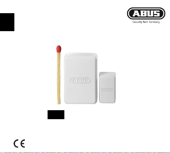
Scope of delivery
(1.) Motherboard housing
(2.) Backplate
(3.) Dust cover
(4.) Magnet holder attachment
(5.) 7 mm plate
(6.) Magnet bracket
(7.) Fixing screws
(8.) Battery
Technical data
Power supply: 3.6 V lithium-thionyl chloride
Battery type: SAFT LS1425 (please use this battery type only)
Power consumption: 0.03 A Battery life: up to 36 months
Radio frequency: 868.6625 MHz/FM Housing material: ABS
Dimensions (LxWxH): 33 x 89 x 29 mm Weight: approx. 53 g
Environmental class: I (-10 to +55°C) Security level: II
- 20 -

Start-up
Insert the battery into the wireless
opening detector.
IMPORTAN
T
Ensure that the
polarity is correct.
See the relevant device information.
Press the tamper switch (anti-removal
wall contact), until the receiver has
received the signal, indicated by a
beep.
Assign the detector in zones
- 21 -

Range
Rabbet
depth
Window/door
frame
Window/door leaf
7 mm magnet
bracket plate
< 19 mm
magnet/detector
magnet/detector
optional
> 19 mm
magnet
detector
compulsory
The range is dependent on environmental factors. Check whether the detector is
communicating properly with the alarm control panel prior to assembly.
When assembling the detector:
do not assemble it on or near metal surfaces.
keep it at least 1 m from gas, water or power lines.
do not assemble it near electronic equipment such computers, photocopiers or
other transmitters and interferences.
Installation location
The optimal installation position for your wireless opening detector is the top corner
of your window/door frame or leaf. Make sure that you install the detector on an
even surface so that the tamper switch (anti-removal wall contact) operates reliably.
The wireless opening detector can be installed on either the window frame or the
leaf of the door.
Select the installation position best suited to the individual location:
- 22 -

For window/door frames with a rabbet depth of less than 19 mm and sufficient
Prior to installation, always check that the distance between the
detector and the magnet is sufficiently short that the magnet can be
reliably detected by the wireless opening detector.
space, we recommend installing the wireless opening detector on the
window/door frame.
(Reverse installation is also possible in this instance, however.)
For window/door frames with a rabbet depth of more than 19 mm, the wireless
opening detector must be installed on the leaf of the window/door using the 7 mm
magnet bracket plate.
To test the detector's triggering function, we recommend pre-assembling the
magnetic bracket and detector base temporarily, using the attached adhesive film
but not the screws.
Once you have checked this, we recommend installing the magnet bracket and
detector base using the screws to secure it in place permanently (you do not need to
pre drill the plastic).
You should always check the rabbet depth of the leaf before making any screw
connections and avoid the screws emerging on the opposite side. (If necessary,
screws may be shortened.)
- 23 -

Installation
The following section describes how to install the wireless opening
detector on the leaf of the window or door.
(Installation on a window or door frame follows the same procedure.)
Position and screw on the backplate
The holes for the fixing screws must be aligned in the
direction of the wall (and not aligned with the centre of
the door/window).
Distance from the door/window edge: 10 mm
(Figure shows window with DIN on right; installation
with DIN on left follows the same procedure.)
Attach motherboard housing
Attach the motherboard housing in the correct position
and press this into place.
(Figure shows window with DIN on right; installation
with DIN on left follows the same procedure.)
10 mm
- 24 -

Attach dust cover
Attach the dust cover (so that the ABUS logo is legible)
and press this into place.
Fit magnet bracket
If the rabbet depth is no more than 19 mm, the
magnet bracket can be fitted without the 7 mm base.
Side-on distance between the magnet bracket and
window leaf max. 3 mm
max. 3 mm
- 25 -

For rabbet heights of up to 20 mm, you will need to use the 7 mm magnet
bracket base. (The base can improve the efficacy of the magnetic contact.)
Side-on distance to the window leaf also max. 3 mm.
- 26 -

Press the magnet bracket including the magnet into the fitted
magnet holder attachment.
Position the magnet in the magnet bracket as shown in the
adjacent illustration.
Before changing the battery, set the alarm system to installer
mode or hide the respective zone (see corresponding device
information).
To change the battery, remove the dust cover together with
the locked motherboard housing by swinging them away
swiftly, and return to their original position once you have
changed the battery.
IMPORTANT
Ensure that the polarity is correct.
Changing the battery
- 27 -

- 28 -
 Loading...