

Page 1
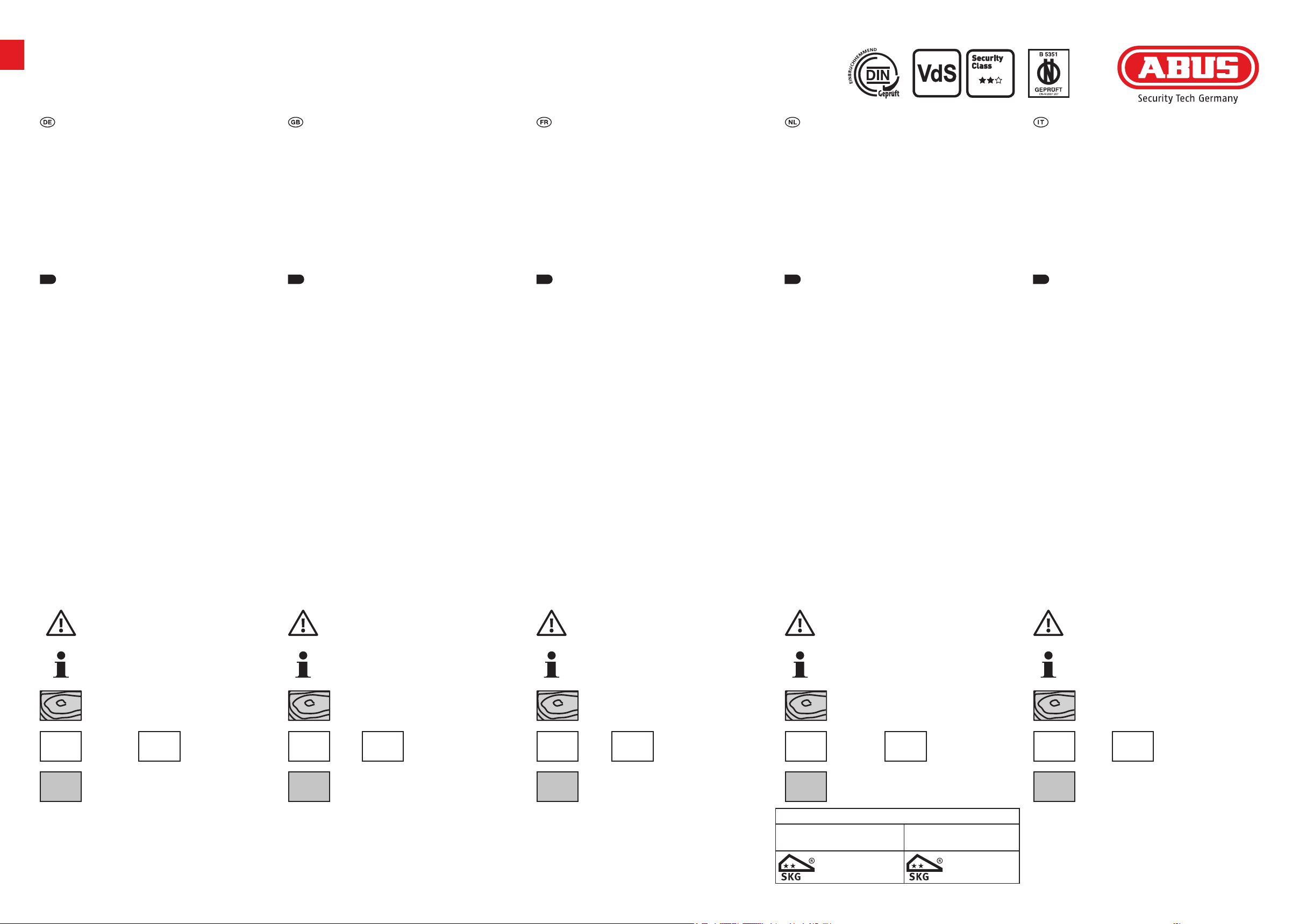
FAS101 / PV101
Fenster-Scharnierseiten-Sicherung
Bitte lesen Sie diese Anleitung vor der Montage und Inbetriebnahme sorgfältig durch. Bewahren Sie die Anleitung
auf und weisen Sie jeden Nutzer auf die Bedienung des Produktes hin.
Inhalt
1. Einsatzbereich und wichtige Hinweise
2. Lieferumfang
3. Montagewerkzeug
4. Montage
5. Bedienung
6. Gewährleistung
Einsatzbereich und wichtige Hinweise
1. 1. 1. 1. 1.
FAS101 wird auf der Scharnierseite von nach innen
önenden Fenstern oder Fenstertüren montiert. Geeignet
sind DIN rechte und linke Fenster aus Kunststo, Holz und
Aluminium. FAS101 ist nach den strengen Prüfanforderungen
der DIN 18104-1 und VdS 2536 anerkannt. Durch DIN Certco
ist FAS101 zertiziert „Einbruchhemmend DIN geprü“.
Gemäß DIN 18104-1 wird empfohlen, dass pro Fenster und
pro 1 Meter Fensterhöhe rechts und links jeweils eine
Zusatzsicherung montiert wird. Polizei und Versicherer
empfehlen dies ebenfalls.
Vor der Montage prüfen Sie bitte die Einstellung des Fensters
bzw. der Fenstertür und ob Ihr Fenster die Mindestmaße
(Abb. 1 - 3) aufweist. Stellen Sie sicher, dass sich das Fenster
/ die Fenstertür einwandfrei önen und schließen lässt.
Die Bohrlochtiefen bzw. Schraubenlängen müssen auf die
örtlichen Gegebenheiten abgestimmt werden. Austreten des
Bohrers bzw. der Schrauben auf der Rückseite vermeiden!
Ggf. mit Bohranschlag arbeiten oder die vorhandenen
Schrauben kürzen.
Bei schlechten Befestigungsmöglichkeiten sollten mehrere
Sicherungen und zusätzlich Befestigungsmittel (ABUS
Befestigungsanker BA oder ABUS Befestigungsset IM100 mit
Verbundmörtel) eingesetzt werden. ABUS Befestigungsmittel
und Verbundmörtel sind im Handel erhältlich. Das in
Abb. 1 genannte ABUS Produkt FTS ist ebenfalls im Handel
erhältlich.
Symbolerklärung
Window hinge security device Sécurité latérale de paumelles de fenêtre
Please read this guide carefully before installation and use.
Keep these instructions and provide all users with instruction on how to use it.
Content
1. Possible uses and important information
2. Scope of delivery
3. Tools re quired
4. Installation instructions
5. Operation
6. Warranty
Possible uses and important information
FAS101 is mounted on the hinge side of the window or
French door. The windows can open to the right or le.
The lock can be tted to PVC, wood or aluminum. FAS101 is
recognized as complying with the strict test requirements
of DIN 18104-1 and VdS 2536. It is certied by DIN Certco as
“Burglar retardant DIN tested”. DIN 18104-1 recommends
that an additional security device should be tted on the
le and right for every meter in height. The police and
insurance companies also give the same recommendation.
Before installation, please check whether your window /
French door complies with the minimum dimensions (g.
1 - 3). Make sure that the window / French door opens and
closes properly. The depths of the drilled holes and screw
lengths must be adjusted to the local conditions. Avoid the
drill or screws from coming out at the back! Possibly work
with drill stopper or shorten the existing screws.
In poor xture conditions, more security devices and
additional fastenings should be used (ABUS xing bolt BA
or ABUS IM100 with composite mortar). ABUS additional
fastenings and composite mortar are available from retail
stores. The ABUS product FTS shown in g. 1 is also available
from retail stores.
Icon explanation
Veuillez lire cette notice attentivement avant le montage et
la mise en service. Conservez ces instructions. Tous les utilisateurs doivent en prendre connaissance.
Teneur
1. Application et indications importantes
2. Contenu de la livraison
3. Outillage
4. Instructions de montage
5. Utilisation
6. Garantie
Application et indications importantes
FAS101 peut être montée sur le côté des paumelles de la
fenêtre ou porte-fenêtre. Les fenêtres peuvent s’ouvrir à
gauche ou à droite. L’installation peut être eectuée sur
des chassis en PVC, bois ou en aluminium. FAS101 répond
aux exigences de contrôle sévères des norms DIN 18104-
1 et VdS 2536. Le certicat DIN indique que FAS101 obtenu
la qualication “anti-eraction DIN”. Selon la norme
DIN 18104-1, il est recommandé de monter une sécurité
complémentaire par fenêtre et par mètre de hauteur
de fenêtre, à gauche comme à droite. La police et les
compagnies d’assurance le recommandement également.
Avant le montage vériez si votre fenêtre / porte-fenêtre
dispose des dimensions minimales indiquées en schéma 1
- 3 et assurez-vous que la fenêtre / porte-fenêtre ouvre et
ferme parfaitement. Les profondeurs de perçage ou plutôt
les longueurs des vis doivent être adaptées aux conditions
locales. Evitez le dépassement de perçage ou de vis sur la
face arrière! Le cas échéant, utilisez une butée de perçage
ou raccourcissez les vis de xation.
En cas de possibilités de xation défavorables, plusieurs
sécurités et des xations supplémentaires (ABUS ancre de
xation BA ou ABUS set de xation IM100 avec mortier)
doivent être prevues. ABUS BA et ABUS IM100 ainsi que le
mortier de xation sont disponibles dans le commerce.
Le produit ABUS FTS illustrée en schéma 1 est également
disponible dans le commerce.
Explanation des symbols
Raam-scharnierzijbeveiliging Sicura per cerniere di finestra
Lees voorafgaand aan de montage en ingebruikname deze
handleiding zorgvuldig door. Bewaar deze handleiding en
informeer iedere gebruiker omtrent de bediening.
Inhoud
1. Toepassing en belangrijke instructies
2. Leveringsomvang
3. Gereedschap
4. Montageaanwijzing
5. Bediening
6. Garantie
Toepassing en belangrijke instructies
De FAS101 wordt aan de scharnierzijde gemonteerd en is
geschikt voor naar binnen draaiende ramen en deuren.
Montage mogelijk op kunststof, hout of aluminium, rechts
of links draaiende ramen. De FAS101 is SKG gecerticeerd
volgens BRL 3104_Hang en sluitwerk en goedgekeurd
volgens de strenge keuringseisen van de norm DIN 18104-
1 en VdS 2536. Door DIN Certco is de FAS101 geceerticeerd
„Inbraakremmend DIN gekeuerd“. Conform DIN 18104-1
wordt aanbevolen om per raam en meter raamhoogte rechts
en links telkens een beveiliging te monteren. Politie en
verzekeraars adviseren dit eveneens.
Voor de montage controleer, of de in a. 1 - 3 aangegeven
minimum afmetingen daadwerkelijk op uw raam /
deur beschikbaar zijn. Zorg ervoor dat het raam / de
deur probleenloos geopend en gesloten kan worden.
De boordieptes en schroeengten moeten aan het
gevelelement aangepast worden. Voorkom doorboren en
-schroeven. Eventueel met een booraanslag werken of de
schroeven inkorten.
Bij slechte bevestigingsmogelijkheden dienen extra
bevestigingsmaterialen (ABUS bevestigingsanker BA of ABUS
bevestigingsset IM100 met chemisch anker) te worden
toegepast. ABUS BA, ABUS IM100 en chemische ankers zijn
in de handel verkrijgbaar. De ABUS product FTS in a. 1 is
eveneens in de handel verkrijgbaar.
Uitleg van de symbolen
Si raccomanda di leggere con attenzione le istruzioni prima
di eseguire il montaggio e la messa in servizio. Conservare
le istruzioni e istruire ogni utente sulle modalità di
funzionamento.
Contenuto
1. Possibilità d‘impiego e avvertenza importante
2. Dotazione
3. Utensili di montaggio
4. Istruzioni di montaggio
5. Uso
6. Garanzia
Possibilità d‘impiego e avvertenza importante
La FAS101 viene montata sul lato della cerniera della nestra
o porta-nestra ed è adatta per tutte le normali nestre
e portenestre che si aprono verso l’interno. Le nestre
possono aprirsi verso destra o verso sinistra. Si può montare
FAS101 su plastica, legno o alluminio. La FAS101 è conforme
ai severi requisiti di controllo della DIN 18104-1 e VdS 2536.
Con la DIN Certco essa è certicata come “Antiscasso conf.
DIN”. Secondo DIN 18104-1 si consigilia di montare per ogni
metro di altezza della nestra, una sicura supplementare sul
lato destro e una sul lato sinistro per ogni nestra. Anche
la polizia e le compagnie d’assicurazione consigliano tali
misure.
Prima del montaggio vericare per favore che le misure
minime indicate nell’ill. 1 - 3 esistano nelle vostre nestre /
porte-nestre. Assicurarsi che la nestra / la porta-nestra si
chiuda e si apra perfettamente. Le profondità per trapanare
i fori, risp. le lunghezze delle viti devono essere adattate alle
condizioni particolari. Evitare che la punta del trapano risp.
la vite fuoriesca dall’altra parte! Se necessario lavorare con
arresto del trapano o accorciare le viti.
Se le possibilità di ssaggio sono scadenti e le possibilità di
erazione dall’esterno sono buone, si dovrebbero utilizzare
mezzi di ssaggio supplementari (ABUS ancora a muro
BA o ABUS kit di ssaggio IM100. Per lo IM100 serve una
malta adatta). ABUS BA e ABUS IM100 come anche la malta
è disponibile in commercio. Anche il prodotto ABUS FTS
ragurati nell’ill. 1 si possono acquistare in commercio.
Descrizione dei simboli
Vorsicht!
Hinweis zur Montage / Bedienung
Holz
PVC PVC
Kunststo /
AL AL AL AL AL
Aluminium
PVC
+ FE
Kunststo mit
Metalleinlage
Caution!
Further tting / using details
Wood
PVC /
Aluminum
PVC
+ FE
PVC with
metal inlay
Attention!
Instructions de montage / utilisation
Bois
PVC
PVC /
Aluminium
PVC
+ FE
PVC avec insert
métallique
Voorzichtig!
Instructies voor de montage / bediening
Hout
PVC
Kunststof /
Aluminium
Gebruik BA of IM100 chemisch anker
Houten-, metaal- of kunststof Kunststof kozijnen
kozijnen met staal versterking zonder staal versterking
zonder ABUS BA in combinatie met
of IM100 ABUS BA of IM100
chemisch anker chemisch anker
PVC
+ FE
Kunststof met
metalen versterking
Attenzione!
Note per l‘installazione / uso
Legno
PVC
PVC /
Aluminio
PVC
+ FE
PVC con inserto
metallico
Page 2
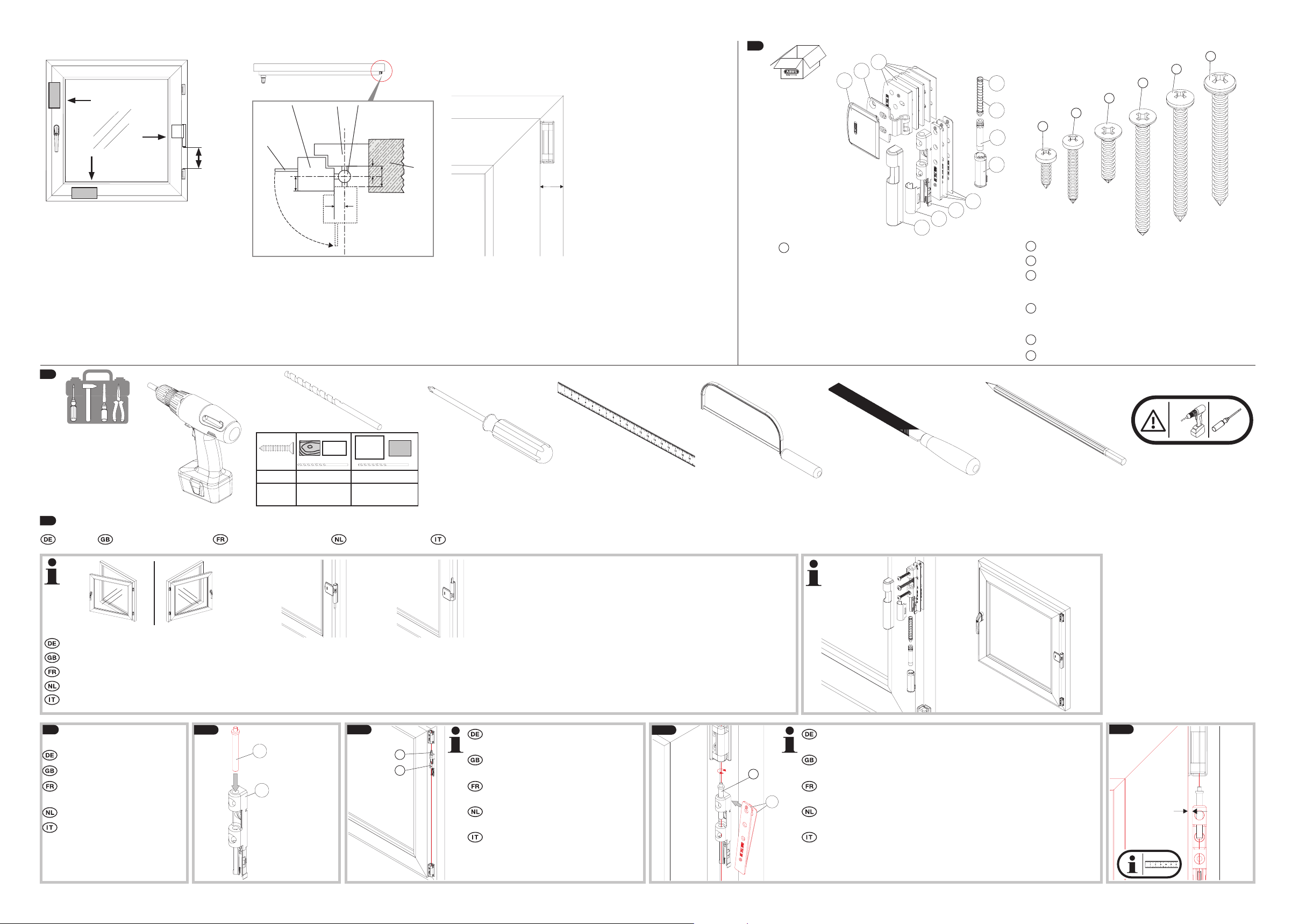
Abb. | fig. | schéma | afb. | ill. 1
S1S2S3S4S5
%1
S6
B
and
and
S1
S2
S3S4S5
S6
F
J
J
FTS
FAS
FTS
3.
> 45 mm
Abb. | fig. | schéma | afb. | ill. 2
Fensterügel
Window
Cadre
Raamvleugel
Battente della
nestra
Glas
Glass
Verre
Glas
Vetri
90°
max.
14 mm
min.
10 mm
Rahmen
Frame
Battant
Kozijn
Telaio
Fensterscharnier
Window hinge
Paumelle
Raamscharnier
Cerniera della nestra
min.
10 mm
min.
21 mm
W
Wall
Mur
W
Muro
Abb. | fig. | schéma | afb. | ill. 3
x*
* x: Mindestabstand Flügel - Wand
• Flügelblech 1: 24 mm
• Flügelblech 2: 32 mm
* x: minimum distance window - wall
• Casement plate 1: 24 mm
• Casement plate 2: 32 mm
* x: distance minimale battant - mur
• Ailette en tôle 1: 24 mm
• Ailette en tôle 2: 32 mm
* x: minimum afstand raam - wand
• Raamplaat 1: 24 mm
• Raamplaat 2: 32 mm
* x: distanza minima battente - parete
• Lamierina 1: 24 mm
• Lamierina 2: 32 mm
2.
*
C
C
B
B
A
A
1 mm
2 mm
3 mm
4 mm
K
K
8 mm
J
J
I
I
H
H
G
G
1 mm
F
F
E
E
D
D
*
Flügelblech 1: für Aufdeckmaß (y) bis 6,5 mm,
Flügelblech 2: für Aufdeckmaß (y) bis 14 mm
Casement plate 1: for covering dimension (y) up to 6,5 mm,
casement plate 2: for covering dimension (y) up to 14 mm
Ailette en tôle 1: pour une couverture (y) jusqu‘à 6,5 mm,
ailette en tôle 2: pour une couverture (y) jusqu‘à 14 mm
Raamplaat 1: voor opdekhoogte (y) tot 6,5 mm,
raamplaat 2: voor opdekhoogte (y) tot 14 mm
Lamierina 1: per gradi di ricoprimento (y) no a 6,5 mm,
lamierina 2: per gradi di ricoprimento (y) no a 14 mm
2 mm
4 mm
1x 5,5 x 50 mm
2x 4,8 x 50 mm
2x 4,8 x 50 mm Senkkopfschraube | Countersunk screw |
Vis à tête conique | Schroef met verzonken kop | Vite a
testa svasata
1x 4,8 x 22 mm Senkkopfschraube | Countersunk screw |
Vis à tête conique | Schroef met verzonken kop | Vite a
testa svasata
2x 3,5 x 25 mm
2x 3,5 x 13 mm
PVC
FE
AL
ø 5,5 mm ø 4,0 mm ø 4,5 mm
ø 4,8 mm ø 3,5 mm ø 3,5 mm
ø 3,5 mm ø 2,5 mm ø 3,0 mm
PVC +
4.
Montage | Installation instructions | Instructions de montage | Montageaanwijzing | Istruzioni di montaggio
R L
U O
Anleitung zeigt die Montage an einem Fenster DIN rechts (R) und mit Betätigung von unten (U). FAS101 kann auch mit Betätigung von oben (O) montiert werden
The instruction show the assembly on a right-hand window (R) and with activation from the bottom (U). FAS101 can also be mounted with activation from the top (O)
La notice de montage illustre le montage sur une fenêtre à droite (R) et avec la commande eectuée par le bas (U). FAS101 peut également être monté avec actionnement par le haut (O)
Instructie beschrij de montage op een raam DIN rechts (R) en met bediening van onderaf (U). FAS101 kan ook worden gemonteerd met bediening van bovenaf (O)
Le istruzioni mostrano il montaggio ad una nestra destra (R) e per azionamento dal basso (U). FAS101 può anche essere montato con azionamento dall‘alto (O)
1.
90
2.
0 %
4.1
Montage der Rahmenleiste
4.1 a
J
Installation of the frame strip
Installation de la platine de
xation
FJF
Installatie van de kozijnlijst
Installazione del listello del
telaio
4.1 b
(F) mit (J) an das Fensterscharnier halten
Hold (F) with (J) against the window
hinge
Maintenez (F) avec (J) contre la paumelle
de fenêtre
(F) met (J) tegen het kozijn-scharnier
houden
Tenere (F) con (J) sulla cerniera della
nestra
4.1 c
Der Mittelpunkt von (J) muss mit der Drehachse der Scharniere oben und
unten übereinstimmen. Ggf. mit Kunststo-Unterlagen (G) auüllen.
The middle point of (J) has to correspond to the turning axis of the hin-
ges at the top and bottom. If necessary, use plastic washers (G) to adjust.
Le point central de (J) doit correspondre à l‘axe des paumelles en haut
GG
et en bas. Si nécessaire, ajustez au moyen des entretoises (G).
Het hart van (J) moet in lijn staan met het draaipunt van het bovenste
en onderste scharnier. Eventueel met opvulplaatjes (G) uitvullen.
Il punto intermedio di (J) deve corrispondere all‘asse di rotazione della
cerniere in alto e in basso. Se necessario, compensare con spessori (G).
4.1 d
X
Page 3

4.1d
F
C
G
4.1 e
X
auf den Fensterrahmen legen. Bohrlöcher anzeichnen.
Take (J) out and place (F) exactly to the distance X to the window
casement measured at 4.1d. Mark the drill holes.
Retirez (J) et placez (F) exactement à la distance X au battant de
fenêtre mesuré à 4.1d. Marquez les positions de perçage.
Verwijder (J) en plaats (F) precies op de afstand X tegen het kozijn
gemeten op 4.1d. Teken de boorgaten af.
Rimuovere (J) e posizionare (F) esattamente alla distanza X al bat-
tente della nestra misurata a 4.1d. Segnare i fori.
X
(J) entnehmen und (F) exakt mit dem in 4.1d ermittelten Abstand X
4.1 f 4.1 g
3 x
3.
ø
Bei Kunststo ohne Metalleinlage anstelle von (S1) ABUS BA / IM100
gemäß Anleitung in die mittlere Bohrung einsetzen.
When working with PVC without metal insert, instead of (S1) insert ABUS
( )
S2
S2
S1
S1
F
F
BA / IM100 into the middle hole, in accordance with the instructions.
En cas d’utilisation de PVC sans insert métallique, placer ABUS BA / IM100
dans le trou central au lieu de (S1) selon les instructions.
Bij kunststof zonder metalen versterking in plaats van (S1) ABUS BA /
IM100 zoals in de handleiding beschreven in de middelste boring
plaatsen.
In caso di PVC senza inserto metallico installare nel foro intermedio ABUS
BA / IM100 invece di (S1) secondo le istruzioni.
4.2
Drucksti einsetzen
Insert the pressure pin
Insérez la tige d‘appui
Plaats de druksti
Inserire il perno di spinta
4.3
Montage des Flügelblechs
Installation of the casement
plate
Installation de l‘ a
Installatie van de raamplaat
Installazione de la lamierina
ilette en tôle
4.2a 4.2b
K
K
J
J
I
I
H
H
ca.
30 mm
4.3a
BCB
1 / 2
4.2c
4.2d 4.2e
click!
EE
click!
C
B1 bzw. B2 laut ermitteltem Aufdeckmaß in Rahmenleiste
einsetzen. Ggf. mit (C) auüllen, so dass B gerade auiegt.
Insert B1 or B2 into frame strip depending on the covering
dimension. If necessary, ll up with (C) so that B lies straight.
Insérer B1 ou B2 en fonction de la dimension de couverture
déterminée dans la bande de cadre. Si nécessaire, remplir
avec (C) pour que B soit à plat.
1.
B1, resp. B2 conform vastgestelde opdekhoogte in kozijnlijst
plaatsen. Eventueel opvullen met (C), zodanig dat B recht ligt.
Installare B1 e B2 secondo il grado di ricoprimento determi-
nato nel listello del telaio. Se necessario, riempire con (C) in
2.
modo tale che B sia appoggiato diritto.
DD
4.3b
B mittig ausrichten und beide
Langlöcher vorbohren.
Align B centrally and pre-drill
both elongated holes.
Alignez B au centre et préforez
les deux trous oblongs.
B centraal uitlijnen en beide
Slobgaten voorboren.
Allineare centrata B e tra-
2 x
3.
ø
panare i due fori ovali.
4.3c 4.3d 4.3e
S6 / S5S6 / S5
check!
(B) + (C) < 10 mm = (S6)
(B) + (C) > 10 mm = (S5)
5.
5.1
Bedienung
Operation
Utilisation
Bediening
Uso
press!
click!
Beim Bohren nicht das Fenstergetriebe beschädigen! Bei Holzfenstern
ca.
15°
schräg Richtung Glasscheibe bohren!
Do not damage the window gear when drilling! Drill diagonally at an
angle of approx. 15° towards the glass panel when drilling into wooden
windows!
Évitez d‘endommager le mécanisme de fenêtre lors du perçage! Pour les
fenêtres en bois, percez env. 15° en diagonale en direction de la vitre!
Bij het boren niet het raammechanisme beschadigen! Bij houten
vensters ca. 15° schuin in de richting van de glazen ruit boren!
3 x
3.
ø
Evitare di danneggiare il meccanismo della nestra durante la trapanare! In caso di nestre in legno, perforare in obliquo con un angolo di
circa 15° in direzione della lastra di vetro!
1. (I) drücken bis zum Einrasten: Fenster gesichert.
2. Önen und Schließen des Fensters möglich
1. Press (I) until it locks: window is secured.
2. Opening and closing the window is possible
1. Appuyez sur (I) jusqu‘à ce qu‘elle verrouille.
2. Ouverture et fermeture de la fenêtre est possible
1. Druk (I) totdat het sluit: Venster beveiligd.
2. Openen en sluiten van het raam is mogelijk
1.
Premere (I) no a ché si innesta: nestra è protetta.
2. Apertura e chiusura della nestra è possibile
4.3f 4.3g 4.3h
S3
S4S3S4
AA
5.2
Zum Kippen des Fensters: (I) drücken zum Herausfahren.
Nach dem Schließen des Fensters (I) wieder hineindrücken.
To tilt the window: release (I) so that it comes out.
Aer closing the window, press (I) again until it locks.
Pour faire osciller la fenêtre: appuyez (I) de façon à ce qu‘il dépasse.
Après la fermeture de la fenêtre, enfoncez (I) jusqu‘à ce qu‘elle verrouille.
Voor het kiepen van het raam: druk op (I) zodat het uitsteekt.
Na het sluiten van het raam (I) weer indrukken.
Per aprire a ribalta la nestra: premere (I) in modo che si sporgano.
Dopo aver chiuso la nestra, reinserire (I) no a ché si innesta.
Page 4

?
6.
Gewährleistung ABUS Produkte sind mit größter Sorg-
falt konzipiert, hergestellt und nach geltenden Vorschrien
geprü. Die Gewährleistung erstreckt sich ausschließlich auf
Mängel, die auf Material- oder Herstellungsfehler zurückzuführen sind. Falls nachweislich ein Material- oder Herstellungsfehler vorliegt, wird das Produkt nach Ermessen von
ABUS repariert oder ersetzt. Die Gewährleistung endet in
diesen Fällen mit dem Ablauf der ursprünglichen Gewährleistungslaufzeit. Weitergehende Ansprüche sind ausdrück-
lich ausgeschlossen.
ABUS haet nicht für Mängel und Schäden, die durch äußere Einwirkungen (z.B. Transport, Gewalteinwirkung),
unsachgemäße Bedienung, normalen Verschleiß und Nicht-
beachtung dieser Anleitung entstanden sind. Bei Geltendmachung eines Gewährleistungsanspruchs ist dem zu bean-
standenden Produkt der originale Kaueleg mit Kaufdatum
und eine kurze schriliche Fehlerbeschreibung beizufügen.
Warranty ABUS products are designed, manufactured
and tested in accordance with applicable regulations with
great care. The warranty exclusively covers faults that are
caused by material or manufacturing defects. If a material
or manufacturing defect can be proven, the product will be
repaired or replaced at the discretion of the warrantor. In
such cases, the warranty ends with the termination of the
original warranty period. Any further claims are expressly
excluded.
ABUS assumes no liability for defects or damage that has
been caused by external inuences (e.g. transport, external
forces), improper use, normal wear and tear or non-compli-
ance with this operating and installation instructions docu-
ment. If a warranty claim is asserted, the product must be
returned with the original receipt with date of purchase and
a brief written description of the fault.
Garantie Les produits ABUS sont conçus, fabriqués et
testés avec beaucoup de soin et selon la réglementation applicable. La garantie couvre uniquement les vices résultant
de défauts matériels ou de fabrication présents au moment
de la vente. En présence d‘un défaut matériel ou de fab-
rication prouvé, le produit est réparé ou remplacé au gré
du donneur de garantie. La garantie se termine, dans de
tels cas, à expiration de la durée d‘origine de la garantie.
Toute revendication au-delà de cette date est explicitement
exclue.
ABUS décline toute responsabilité pour des vices et dom-
mages résultant des inuences extérieures (p.ex. avaries de
transport, emploi de la force), d‘une utilisation inappropriée, de l‘usure normale ou de la non-observation des pré-
sentes instructions. En cas d‘une demande dans le cadre
de la garantie, l‘article réclamé doit être accompagné du
justicatif mentionnant la date d‘achat et d‘une description
du défaut.
Garantie ABUS producten zijn met de grootste zorg-
vuldigheid ontworpen, geproduceerd en op basis van de
geldende voorschrien getest. De garantie hee uitsluitend
betrekking op gebreken die op materiaal- of fabrieksfouten
duiden op het moment van verkoop. Bij bewijs van een
materiaal- of fabrieksfout wordt de product na beoordeling
van de garantiegever gerepareerd of vervangen. De garantie
eindigt in dit geval met het aopen van de oorspronkelijke
garantieperiode. Verdergaande aanspraken zijn uitdrukkelijk
uitgesloten.
ABUS is niet aansprakelijk voor gebreken en schade die zijn
veroorzaakt door inwerkingen van buitenaf (bijvoorbeeld
door transport, inwerking van geweld), onjuist gebruik,
normale slijtage of het niet in acht nemen van deze handleiding. Bij het indienen van een garantieclaim moet bij
de product het originele aankoopbewijs met datum van de
aankoop en een korte schrielijke beschrijving van de fout
worden gevoegd.
Garanzia I prodotti ABUS sono progettati con la massima cura, construito e collaudato in conformità alle direttive vigenti in materia. La garanzia copre esclusivamente
gli inconvenienti a difetti di materiale o di fabbricazione.
Nel caso in cui sia comprovato un difetto di materiale o
di fabbricazione il prodotto verrà riparato o sostituito a
discrezione del garante. La garanzia di qualità termina in
questi casi alla scadenza del periodo originario di garanzia.
Si escludono espressamente ulteriori pretese.
ABUS non è responsabile per difetti o danni causati da
fattori esterni (ad esempio trasporto, uso forzato), da un
utilizzo non appropriato, dal normale logoramento o dal-
le mancata osservanza delle presenti istruzioni. Qualora si
faccia valere una pretesa di garanzia, allegare al prodotto
d‘acquisto originale contente la data d‘acquisto, e una bre-
ve descrizione scritta del difetto.
Technische Änderungen vorbehalten. Für Druckfehler und
Irrtümer keine Haung.
© ABUS 2018 | ABUS August Bremicker Söhne KG | D 58292 Wetter | Germany.
Tel.: +49 (0) 23 35 63 40 | |
Subject to technical alterations. No liability for mistakes and
printing errors.
Nous nous réservons le droit de toutes modications
techniques. Nous n‘assumons aucune responsabilité pour
des erreurs ou défauts d‘impression éventuels.
Technische wijzigingen voorbehouden. Geen aansprakelijkheid voor vergissingen en drukfouten.
Ci si riservano modiche tecniche. Per errori e refusi di
stampa non ci si assume alcuna responsabilità.
T390332 | V3 | J18
 Loading...